Panasonic CW-XC82YU Manual de usuario
- Tipo
- Manual de usuario
La página se está cargando...

2
• Please observe the following safety precautions when using your air conditioner.
Failure or negligence in observing these safety precautions could cause fire, electrical shock or personal injury.
• Por favor observe las siguientes precauciones de seguridad cuando use su acondicionador de aire.
Si usted no observa las precauciones, puede resultar en incendio, choque eléctrico o heridas personales.
This symbol (with a white background) denotes an action that is
PROHIBITED.
Este símbolo (con un fondo blanco) denota una acción que
es PROHIBIDO.
These symbols (with a blue background) denote actions that are
COMPULSORY.
Estos símbolos (con fondo azul) denotan acciones que son
OBLIGATORIAS.
SAFETY PRECAUTIONS
PRECAUCIONES DE SEGURIDAD
SAFETY PRECAUTIONS
PRECAUCIONES DE SEGURIDAD
• Due to the weight of this product, we recom-
mend that you have a helper to assist in the
installation. To avoid injury, use the proper
method of lifting. Avoid any sharp edges.
• Debido a que este producto es muy pesado, le
recomendamos que tenga un asistente para
ayudarlo en la instalación. Para evitar lesiones,
use un modo propio para levantarlo. Aléjese
de los bordes afilados.
• Make sure the window frame to be used can
properly support this product.
• Asegúrese que el marco de la ventana que se
usará puede soportar apropiadamente este
producto.
• This product must be installed in accordance
with all local codes and ordinances.
• Este producto debe ser instalado de acuerdo
con las leyes y regulaciones locales.
• Do not install the unit in places where
inflammable gas, fumes or soot may be generated.
• No instale la unidad cerca de lugares, donde
puedan ser producidos gases inflamables,
emanaciones de humo u hollín.
Installation Precautions
Precauciones de Instalación
• Operate your air conditioner from a stable
115 volt AC supply.
• Haga funcionar su acondicionador de aire desde
una fuente de alimentación de CA de 115 voltios.
• Plug into a separate 15 amp grounded outlet only.
• Enchúfelo sólo en un tomacorriente separado
de 15 amp con conexión a tierra.
• Use of extension cords
Avoid using extension cords. If there are no
alternatives, ensure that the cord is a UL listed
3-wire grounding type, rated 125 volts with a
minimum current-carrying rating of 15 amps,
number 14 or heavier wire.
• Utilización de cables de extensión
No use cables de extensión. Si no existiera otra
posibilidad, debería ser un cable de 3 alambres
con conexión a tierra de tipo UL, de 125 voltios
con un amperaje mínimo de 15 amp, de alambre
número 14 o mayor.
• Use a 15 amp time delay fuse or a circuit breaker.
• Use un fusible de retardo de 15 amp o un
interruptor automático.
• Do not switch off by unplugging the power plug
while it is operating. Press the OFF/ON pad to
“OFF” before unplugging.
• No desconecte desenchufando el enchufe de
alimentación mientras esté funcionando.
Presione el botón OFF/ON para desconectar
antes de desenchufar.
Operation Precautions
Precauciones de Operación
Power Supply
Suministro de Electricidad
Time Delay Fuse : 15 Amps
Fusible de Retardo : 15 Amp
Rated Voltage : 115V
Voltaje :115V
Line Cord Plug
Cable de
Alimentación de
Corriente
Socket Type
Tipo de enchufe
La página se está cargando...

4
AIR CONDITIONER INSTALLATION
INSTALACIÓN DEL ACONDICIONADOR DE AIRE
AIR CONDITIONER INSTALLATION
INSTALACIÓN DEL ACONDICIONADOR DE AIRE
CAUTION
CUIDADO
Please remove the shipping blocks
fixed to the compressor and front
grille before installation.
Por favor remueva los tacos de envío
fijados en el compresor y la rejilla
frontal antes de la instalacíon.
Compressor
Compresor
Shipping blocks
Tacos de envío
BACK VIEW
VISTA TRASERA
ACCESSORIES
ACCESORIOS
Note : Check that none of the
accessories are missing.
Nota : Compruebe que no falte
ninguno de los accesorios.
(6 pcs)
(6 piezas)
(4 pcs)
(4 piezas)
(8 pcs)
(8 piezas)
Tape Measure
Cinta métrica
Pencil
Lápiz
Level
Nivel
Knife or Scissors
Cuchilla o tijeras
SUGGESTED TOOL LIST
LISTA DE HERRAMIENTAS SUGERIDAS
Medium sized screwdriver (#2 Phillips)
Destornillador mediano (Phillips No. 2)
Front grille
Rejilla frontal
Front grille
Rejilla frontal
REMOVE
REMUEVA
SCREWS
FURNISHED
TORNILLOS
SUMININSTRADOS
Type A Type B Type C
Tipo A Tipo B Tipo C
Type Part no. Remarks Qty.
Tipo Parte no. Comentario Cantidad
A
CWH55207A
Wood Screw
6
Tornillo para madera
B
CWH55330
Tapping Screw
4
Tornillo de rosca
C
CWH55222A
Machine Screw
8
Tornillo para metales
INSTALLATION BOX CONTENTS
CONTENIDO DE LA CAJA DE INSTALACIÓN
Right side
expandable panel
Lado derecho del
panel extensible
Bottom bracket
Soporte inferior
Type C screws
Tornillos tipo C
Left side
expandable panel
Lado izquierdo del
panel extensible
Panel retainer
Retenedor del panel
Type A screws
Tornillos tipo A
Type A screws
Tornillos tipo A
Type B screws
Tornillos tipo B
Panel retainer
Retenedor del panel
Type B screws
Tornillos tipo B
Sealer 50 g
(1.8 oz) (Putty)
Sellador 50 g
(1,8 oz) (Masilla)
Window sash foam seal
Espuma de sellado de la
hoja móvil de la ventana
Top bracket
Soporte superior
Window sash sealing ribbon
Cinta de sellado de la hoja
móvil de la ventana
O
F
F
/
O
N
O
P
E
R
A
T
I
O
N
T
EM
P
/
T
I
M
E
R
C
O
O
L
F
A
N
H
I
G
H
M
E
D
L
O
W
M
O
D
E
F
A
N
S
P
E
E
D
S
E
T
T
I
M
E
R
S
E
T
/
C
A
N
C
E
L
h
r
F
E
C
O
N
O
M
Y
W
i
r
e
l
e
s
s
R
e
m
o
t
e
C
o
n
t
r
o
l
Front intake grille
Rejilla frontal de la
toma de aire

5
• Hot sun rays hitting the outside surface of the cabinet will create considerable heat
load. If the outside of the cabinet is exposed to direct sunlight, consider building an
awning to shade the cabinet while providing ample area for the heated air to be exhausted
from the condenser (both sides) and the top.
This unit is designed for installation in standard double hung windows. However, it
may also be installed in a sliding window using the optional installation kit (ME-68S
and CZ-MW4-P) available through your local dealer or parts distributor.
NOTE: The unit may also be installed “through the wall”. You should, however,
observe standard carpentry practices and frame the opening without violating
local ordinances.
• Los rayos solares que tocan la superficie exterior de la caja crearán una considerable
carga de calor. Si la parte que da al exterior de la caja está bajo la luz directa del sol,
considere el construir un toldo para dar sombra pero dejando espacio suficiente para
que el aire caliente pueda ser expulsado del condensador (en ambos lados) y parte
superior.
Este aparato está diseñado para ser instalado en ventanas levadizas dobles. Sin em-
bargo, se pueda instalar también en una ventana de corredora utilizando los avíos de
instalación optativos (ME-68S y CZ-MW4-P) que están disponibles por medio de su
comerciante local o distribuidor de partes.
NOTA: Esta unidad tambíen se puede instalar a través de la pared. En este caso, se
deberán realizar trabajos de carpintería y construir una estructura en la abertura
deacuerdo con los reglamentos locales.
WINDOW REQUIREMENTS
REQUISITOS DE LA VENTANA
21-
21
/
32
to 35-
7
/
16
21-
21
/
32
a 35-
7
/
16
PREPARATION OF AIR CONDITIONER CHASSIS
PREPARACIÓN DEL CHASIS DEL ACONDICIONADOR DE AIRE
Remove the front intake grille
Quite la rejilla frontal de la toma de aire
Push and release.
Presione y suelte.
C
L
O
S
E
V
E
N
T
O
P
E
N
O
F
F
/
O
N
O
P
E
R
A
T
I
O
N
T
E
M
P
/
T
I
M
E
R
C
O
O
L
F
A
N
H
I
G
H
M
E
D
L
O
W
M
O
D
E
F
A
N
S
P
E
E
D
S
E
T
T
I
M
E
R
S
E
T
/
C
A
N
C
E
L
h
r
F
E
C
O
N
O
M
Y
W
i
r
e
l
e
s
s
R
e
m
o
t
e
C
o
n
t
r
o
l
Slide the front intake grille slightly to the left to unhook
the tabs.
Deslice la rejilla frontal de toma de aire un poco a la
izquierda para descolgar las lengüetas.
Lift up to about
90° and remove.
Levante hasta
más o menos 90˚
y quite.
C
L
O
S
E
V
E
N
T
O
P
E
N
O
F
F
/
O
N
OPERATION
T
E
M
P
/
T
I
M
E
R
C
O
O
L
F
A
N
H
I
G
H
M
E
D
L
O
W
M
O
D
E
F
A
N
S
P
E
E
D
S
E
T
T
I
M
E
R
S
E
T
/
C
A
N
C
E
L
h
r
F
ECONOMY
W
i
r
e
l
e
s
s
R
e
m
o
t
e
C
o
n
t
r
o
l
Remove the air filter
Quite el filtro de aire
C
L
O
S
E
V
E
N
T
O
P
E
N
O
F
F
/
O
N
O
P
E
R
A
T
IO
N
T
E
M
P
/
T
I
M
E
R
C
O
O
L
FA
N
H
I
G
H
M
E
D
L
O
W
M
OD
E
FA
N
S
P
E
E
D
S
E
T
T
I
M
E
R
S
E
T
/
C
A
N
CE
L
h
r
F
E
C
O
N
O
M
Y
W
i
r
e
l
e
s
s
R
e
m
o
t
e
C
o
n
t
r
o
l
Air filter
Filtro de aire
Tilt up and pull out the air filter by the holder.
Incline y saque el filtro por el soporte.
SELECT THE BEST LOCATION
(Single or Double hung window)
ELIJA LA MEJOR UBICACIÓN
(Ventana de guillotina simple o doble)
Front grille
Rejilla frontal
Indoor side
Lado interior
18–
11
/
16
inches
18–
11
/
16
pulgadas
O
F
F
/
O
N
O
P
E
R
A
T
I
O
N
T
E
M
P
/
T
I
M
E
R
C
O
O
L
F
A
N
H
I
G
H
M
E
D
L
O
W
M
O
D
E
F
A
N
S
P
E
E
D
S
E
T
T
I
M
E
R
S
E
T
/
C
A
N
C
E
L
h
r
F
E
C
O
N
O
M
Y
W
i
r
e
l
e
s
s
R
e
m
o
t
e
C
o
n
t
r
o
l
Window
Ventana
SIDE VIEW
VISTA
LATERAL
Front grille
Rejilla frontal
Window
Ventana
Outdoor side
Lado exterior
12 inches
12 pulgadas
12 inches
12 pulgadas
More than 4 inches
Más de 4 pulgadas
NOTE: It is much easier, and also safer, to install the
empty cabinet into a window first and we
suggest that you follow this procedure.
NOTA: Es mucho más fácil y también más seguro
instalar primero la caja vacía en la ventana.
Nosotros sugerimos, que lo haga así.
14 -
1
/
4
(min)
14 -
1
/
4
(minimo)

6
O
F
F
/
O
N
O
P
E
R
A
T
I
O
N
T
E
M
P
/
T
I
M
E
R
C
O
O
L
F
A
N
H
I
G
H
M
E
D
L
O
W
M
O
D
E
FAN SPEED
S
E
T
T
I
M
E
R
S
E
T
/
C
A
N
C
E
L
h
r
F
E
C
O
N
O
M
Y
W
i
r
e
l
e
s
s
R
e
m
o
t
e
C
o
n
t
r
o
l
O
F
F
/O
N
O
P
E
R
A
T
I
O
N
T
E
M
P
/
T
I
M
E
R
C
O
O
L
F
A
N
H
I
G
H
M
E
D
L
O
W
M
O
D
E
F
A
N
S
P
E
E
D
S
E
T
T
I
M
E
R
S
ET
/
CA
NC
EL
h
r
F
E
C
O
N
O
M
Y
W
i
r
e
l
e
s
s
R
e
m
o
t
e
C
o
n
t
r
o
l
AIR CONDITIONER INSTALLATION
INSTALACIÓN DEL ACONDICIONADOR DE AIRE
AIR CONDITIONER INSTALLATION
INSTALACIÓN DEL ACONDICIONADOR DE AIRE
HOW TO ASSEMBLE THE EXPANDABLE PANELS (LEFT & RIGHT)
COMO ARMAR LOS PANELES EXPANSIBLES (IZQUIERDO Y DERECHO)
Remove the front grille
Quite la rejilla frontal
Unscrew and remove the chassis locking
brackets (1 chassis grounding screw and
2 screws). Keep for later use.
Desatornille y quite los soportes que
cierran el chasis (1 tornillos del chasis
a tierra y dos tornillos). Guardelos para
futuro uso.
Remove the chassis locking brackets
Quite los soportes que cierran
el chasis
Counter clockwise.
En sentido contrario al reloj.
Slide the chassis out from the cabinet
Deslice el chasis hacia afuera del caja
Chassis grounding screw
Tornillos del chasis a tierra
Counter clockwise.
En sentido
contrario al reloj.
Top bracket
Soporte superior
Attach the top and bottom bracket to
the cabinet using screw type C (6 pcs).
Fije los retención superior e interior a
el caja utilizando tornillos tipo C
(6 piezas).
Front grille
Rejilla frontal
Panel retainer
(The panel retainers are packed in the folds of the expansion panels.)
Retenedor del panel
(Las placas de retención del panel están empacadas en los pliegues de
los paneles expansibles.)
Bottom bracket
Soporte inferior
Insert expandable panels into
the top and bottom brackets.
Inserte los paneles
expansibles en los soportes
de arriba abajo.
Attach a panel retainer on the first
fold of each expansion panel and
secure panel retainers to cabinet
using screw type B (2 each).
Inserte la placa de retención del
panel dentro del primer pliegue de
cada uno de los paneles expansibles
y retenedor del panel al caja usando
los tornillos tipo B (2 cada uno).
Remove the adhesive tape from all sides of
the front grille.
At bottom right side of the front grille, press
inward on cabinet near the power cord, and
pull the grille outward to the right until right
tab releases.
At the bottom left side, push inward on
cabinet and pull the grille outward to the
left to release the left tab.
Do not pull the bottom edge toward you
more than 3 inches to prevent the two top
tabs from damage.
Slide the front grille upwards to free the two
top tabs from slots at the top of the cabinet.
Chassis locking brackets
Soportes que cierran
el chasis
O
F
F
/
O
N
O
P
E
R
A
T
I
O
N
T
E
M
P
/
T
I
M
E
R
C
O
O
L
F
A
N
H
I
G
H
M
E
D
L
O
W
M
O
D
E
FA
N
SPE
ED
S
E
T
T
I
M
E
R
S
E
T
/
C
A
N
C
E
L
h
r
F
E
C
O
N
O
M
Y
W
i
r
e
l
e
s
s
R
e
m
o
t
e
C
o
n
t
r
o
l
Quite las cintas adhesivas de los lados
de la rejilla frontal.
En la parte inferior derecha de la rejilla
frontal, presione hacia dentro en el
mueble al lado del cordón de
alimentación y tire de la rejilla hacia fuera,
hacia la derecha, hasta desenganchar la
lengüeta derecha.
En el lado inferior izquierdo, presione hacia dentro en el mueble y tire
de la rejilla hacia fuera, hacia la izquierda, para desenganchar la lengüeta
izquierda.
No tire del borde inferior, hacia usted, más de 3 pulgadas para impedir
que las dos lengüetas superiores se dañen.
Deslice la rejilla frontal hacia arriba para liberar las dos lengüetas
superiores de las ranuras en la parte superior del mueble.

7
O
F
F
/
O
N
O
P
E
R
A
T
IO
N
T
E
M
P
/
T
I
M
E
R
C
O
O
L
F
A
N
H
I
G
H
M
E
D
L
O
W
M
O
D
E
F
A
N
S
P
E
E
D
S
E
T
T
I
M
E
R
S
E
T
/
C
A
N
C
E
L
h
r
F
E
C
O
N
O
M
Y
W
ire
le
s
s
Remote Control
CABINET INSTALLATION
INSTALACION DEL CAJA
• Expand the expandable panel fully into the grooves of the
window frame, secure the expandable panel, left, right and
top mounting frames to the bottom of the window sash
using 6 type A screws and 2 type C screws.
• Secure the cabinet using 2 type A wood screws.
• Cut the window sash foam seal to the proper size and
seal the opening between the top of the inside window
sash and the outside window sash.
Note : If a gap exists between the unit and window sash,
you may use “Sealer” supplied with the installation
kit for a better seal.
Window sash sealing ribbon
Cinta de sellado de la hoja
móvil
Cut the “Sealing Ribbon” to the proper length, and attach it
along the bottom edge of the bottom window sash.
Corte la cinta de sellar del largo apropiado y colóquela a lo
largo de la parte inferior de la ventana de guillotina.
To prevent condensation water from dripping inside, the cabinet
should be installed level or very slightly tilted to the outside.
Para prevenir que el agua de condensación gotee dentro, el
caja debe ser instalada al nivel o con una muy ligera inclinación
desde adentro hacia fuera.
Secure the cabinet using screws.
Fije la caja usando los tornillos.
Type A screw
Tornillo tipo A
Window sill
Alféizar de la
ventana
Type A screws
Tornillos tipo A
Expandable panel
Panel extensible
Type A screws
Tornillos tipo A
Type C screws
Tornillos tipo C
• Expande el panel extenible completamente dentro del marco de la
ventana, asegúrelo a la parte inferior de la hoja de la ventana por la
izquierda, a la derecha y por la parte superior, usando 6 tornillos tipo
A y 2 tornillos del tipo C.
• Fije la caja usando 2 tornillos para madera tipo A.
• Corte la cinta para sellar de la hoja de la ventana del tamafío correcto
y selle la abertura entre la parte superior del interior y del exterior
de la hoja de la ventana.
Nota : Si existiera un espacio entre la unidad y la hoja de la ventana,
puede usar el sellador que está dentro del paquete de instalación,
para obtener un mejor sellado.
CHASSIS INSTALLATION INTO THE CABINET
INSTALACIÓN DEL CHASIS DENTRO DE LA CAJA
Slide the chassis into the cabinet
Deslica el chasis dentro del caja
Inside of sash
Interior de la hoja móvil
Top bracket
Soporte superior
Sealing ribbon
Cinta de sellar
Window sash
Hoja de la ventana
Outside of sash
Exterior de la hoja móvil
La página se está cargando...

9
Condensed water drainage
Drenaje de agua condensada
HOW TO ATTACH THE DRAIN PAN (OPTIONAL)
COMO INSTALAR LA BANDEJA DE DRENAJE (OPCIONAL)
Maximum
13/32”
Máxima
de 13/32”
Condensed water
Agua condensada
Slide the chassis out from the
cabinet (refer to page 6) and
remove the rubber plug.
Deslice el chasis hacia afuera del
caja (diríjase a la página 6) y
quite el tapon de goma y
Remove the
rubber plug
Quite el
tapón de
goma
Note: Drain hose or tubing can be purchased locally to satisfy your particular needs.
Nota: El tubo o la manguera de drenaje puede ser comprado localmente de acuerdo
a sus necesidades particulares.
This air conditioner employs a “Slinger-Up
System” which is designed to splash the
condensed water on the condenser coil for
maximum cooling efficiency, thus producing
a splashing sound.
If the splashing sound annoys you, you can
provide an outside drainage by using the
following procedure which may, however,
cause a small loss of performance.
O
F
F
/
O
N
O
P
E
R
A
T
I
O
N
T
E
M
P
/
T
I
M
E
R
C
O
O
L
F
A
N
H
I
G
H
M
E
D
L
O
W
M
O
D
E
F
A
N
S
P
E
E
D
S
E
T
T
I
M
E
R
S
E
T
/
C
A
N
C
E
L
h
r
F
E
C
O
N
O
M
Y
W
i
r
e
l
e
s
s
R
e
m
o
t
e
C
o
n
t
r
o
l
INTERNAL VIEW
VISTA INTERIOR
PLACE FRONT INTAKE GRILLE OVER THE FRONT GRILLE
COLOQUE LA REJILLA FRONTAL DE TOMA DE AIRE SOBRE LA REJILLA FRONTAL
Slide the front intake grille slightly to the right to reattach the tabs and then
push it down to close tight.
Deslice la rejilla frontal de toma de aire un poco a la derecha para readjuntar
las lengüetas y luego tire hacia abajo para dejar bien cerrado.
NOTE: A “click” sound can be heard when the front intake grille is pushed
down.
NOTA: Se puede escuchar un “click” cuando la rejilla frontal de la toma
de aire es empujada hacia abajo.
Note: The drain pan (part no. CWH40175) can
be obtained from nearest servicenter.
Nota: La bandeja de drenaje (serie no.
CWH40175) puede ser obtanido en su
servicentro más cercano pagadero.)
Install the optional drain pan (part no. CWH40175)
Instale la bandeja opcional de drenaje (serie no.
CWH40175)
Install the drain pan at
the right corner of the
cabinet using 2 screws
(part no. CWG86C733).
Instale la bandeja de
drenaje en la esquina
derecha de la caja con
dos tornillos (serie no.
CWG86C733).
Screws
Tornillos
Drain pan (optional)
Bandeja de drenaje (opcional)
Slide the chassis back into the cabinet
Re-install the chassis locking brackets
Deslice el chasis hacia el interior de la caja
Reinstale los soportes de bloqueo del chasis
Connect a drain hose (optional)
Conectar la manguera de drenaje (opcional)
Fit the drain
hose to the
drain pan.
Inserte la
manguera
de drenaje a
la bandeja
de drenaje.
EXTERNAL VIEW
VISTA EXTERIOR
Under-side view with drain pan and hose
in place.
Vista inferior con la bandeja de drenaje y
la manguera de drenaje ya instaladas.
Note: The cabinet should be installed tilted slightly lower to the rear for
necessary condensate drainage. (Max. 13/32”)
Este acondicionador de aire emplea un “Sistema de lanzado” el cual esta
diseñado para salpicar el agua condensada en el rollo del condensador
para maximizar la eficiencia de enfriamiento, por esto se produce un
sonido de salpicadura. Si el sonido de la salpicada le molesta, puede proveer
un drenaje externo siguiendo el procedimiento de a continuación que
purde, sin embargo, disminuir el grado de funcionamiento.
Nota: El armario debe de estar un poco inclinado, más bajo que la parte
trasera para el drenaje necesario de la condensación. (Máxima de 13/32”)
Drain hose
(not included)
Manguera de
drenaje
(no incluido)

10
VENTILATION LEVER
PALANCA DE VENTILACIÓN
When the slide lever is in the :
Cuando la palanca se encuentra deslizada
en la:
– “OPEN” position, the ventilation door
opens to allow air, smoke or odors to
be expelled from the room.
– Posición “OPEN”, la puerta de
ventilación está abierta para permitir
que el aire, humo u olor sean
expulsados de la habitación.
When the slide lever is in the :
Cuando la palanca se encuentra deslizada
en la:
– “CLOSE” position, the ventilation door
is closed and the air will be circulated
inside the room and conditioned.
– Posición “CLOSE”, la puerta de
ventilación está cerrada y el aire circula
dentro de la habitación y así
acondicionará.
O
F
F
/
O
N
O
P
E
R
A
T
I
O
N
T
E
M
P
/T
IM
E
R
C
O
O
L
F
A
N
H
I
G
H
M
E
D
L
O
W
M
O
D
E
F
A
N
S
P
E
E
D
S
E
T
T
I
M
E
R
S
E
T
/
C
A
N
C
E
L
h
r
F
E
C
O
N
O
M
Y
C
L
O
S
E
V
E
N
T
O
P
E
N
W
i
r
e
l
e
s
s
R
e
m
o
t
e
C
o
n
t
r
o
l
MAIN UNIT
UNIDAD PRINCIPAL
PART IDENTIFICATION
IDENTIFICACIÓN DE LOS COMPONENTES
PART IDENTIFICATION
IDENTIFICACIÓN DE LOS COMPONENTES
Airflow Direction Vane
Vertical Airflow Direction Adjustment Up-Down
The vertical airflow direction vane is controlled by positioning the vane to discharge the air
upwards, downwards or straight out.
Horizontal Airflow Direction Adjustment Side-to-Side
The horizontal airflow direction vane is controlled by positioning the vane to discharge the air to
the right, left or straight out.
Veleta de control de dirección de la corriente de aire
Corriente de aire en dirección vertical de ajuste hacia arriba y hacia abajo
La dirección vertical de la corriente de aire se controla colocando la veleta de manera que
descargue la corriente de aire hacia arriba, hacia abajo o de frente.
Corriente de aire en dirección horizontal de ajuste lateral
La dirección horizontal de la corriente de aire se controla colocondo la veleta de manera que
descargue la corriente de aire hacia la derecha, hacia la izquierda o de frente.
ACCESSORIES
ACCESORIOS
Remote control
Telecontrol
Two “AAA” dry-cell batteries
Dos “AAA” pilas
Air inlet louver
Tomas de aire para ventilación
Cabinet
Caja
Air filter (behind the front intake grille)
Filtro de aire (detras de la rejilla frontal de toma de
aire)
Front intake grille
Rejilla frontal de toma de aire
Front grille
Rejilla frontal
Power cord
Cable de suministro
O
F
F
/
O
N
O
P
E
R
A
T
I
O
N
T
E
M
P
/
T
I
M
E
R
C
O
O
L
F
A
N
H
I
G
H
M
E
D
L
O
W
M
O
D
E
F
A
N
S
P
E
E
D
S
E
T
T
I
M
E
R
S
E
T
/
C
A
N
C
E
L
h
r
F
E
C
O
N
O
M
Y
W
ir
e
le
s
s
R
e
m
o
t
e
C
o
n
t
r
o
l

11
TOUCH CONTROL PANEL
TABLERO DE INSTRUMENTOS
TYPES OF SIGNAL SOUND
TIPOS DE SEÑALES SONOROS
One long “beep” and one short “beep”.
(emitted by the main unit.)
Un “beep” de larga duración y un breve “beep”.
(omitido por la unidad principal)
CANCEL SIGNAL SOUND
SEÑAL DE ANULACIÓN
To cancel signal sound, press and hold OFF/ON for
over 10 seconds. Repeat this to restore signal sound.
Note: The cancelling or restoring of signal sound
shall be done before the unit starts to operate.
Para que se escuche la señal de anulación, presione
y sujete OFF/ON durante más de 10 segundos.
Repita esto para recuperar el sonido de la señal.
Nota: La cancelación o recuperación de la señal se
hará antes de ponerse el aparato en funcionamiento.
REMOTE CONTROL
TELECONTROL
Be sure to observe the following:
Asegura que estas reglas estén respectadas:
• Aim remote control at control panel on air conditioner when
operating.
• Do not drop or throw the remote control.
• Do not place the remote control where it is exposed to direct sunlight
or next to a heating unit or other heat sources.
• Apunte al control remoto en el panel de control en el acondicionador
de aire cuando esté en funcionamiento.
• No caer ni tirar el telecontrol.
• No poner el telecontrol donde esta expuesto a la luz del sol ni cerca
de une fuente de calor.
O
F
F
/
O
N
O
P
E
R
A
T
I
O
N
T
E
M
P
/
T
I
M
E
R
C
O
O
L
F
A
N
H
I
G
H
M
E
D
L
O
W
M
O
D
E
F
A
N
S
P
E
E
D
S
E
T
T
I
M
E
R
S
E
T
/
C
A
N
C
E
L
h
r
°
F
E
C
O
N
O
M
Y
W
i
r
e
l
e
s
s
R
e
m
o
t
e
C
o
n
t
r
o
l
* Maximum distance : 10m (32.8 ft.)
* Distancia máxima : 10m (32,8 ft.)
OPERATION button
Botón de selección OPERATION
TIMER button
Botón arreglo del programador
MODE selection button
Botón de selección del modo
Signal Transmitter
Transmisor de señales
TEMPERATURE/TIMER setting button
Botón regulador de temperatura
TIMER SET/CANCEL button
Botón SET/CANCEL arreglo del programador
ECONOMY Button
Botón ECONOMY
FAN SPEED Selection Button
Botón regulador de velocidad del ventilador
OFF/ON
OPERATION
TEMP/TIMER
COOL
FAN
HIGH
MED
LOW
MODE
FAN SPEED
SET
TIMER
SET/
CANCEL
hr
°F
ECONOMY
Wireless
Remote Control
Panasonic
MODE
OPERATION
FAN SPEED
ECONOMY
SET/
CANCEL
TEMP/TIMER
TIMER
Display Panel
Pantella de visualización
MODE selection pad
Botón de selección del modo
FAN SPEED selection pad
Botón de control de la velocidad del ventilador
TEMPERATURE/TIMER setting pad
Botón del programador de temperatura
Timer SET/CANCEL pad
Botón de SET/CANCEL del programador
TIMER pad
Botón del programador
OFF/ON pad
Botón de conectar/desconectar
ECONOMY pad
Botón ECONOMY

12
Close the compartment
cover.
Cerrar la tapa del
compartimiento.
How to insert batteries
Introducción de la pilas
About the batteries
Notas sobre la pilas
• The batteries can be used for approximately one year.
• Do not use rechargeable (Ni-Cd) batteries, because such batteries differ from the standard dry cell batteries in shape,
dimension and performance.
• Be sure to replace the batteries with two new identical batteries.
• Remove the batteries if the air conditioner will not be used for an extended period of time.
• Se pueden utilizarse durante mas o menos un año.
• No puede utilizar pilas que se recargan (Ni-Cd) porque esas tienen diferentes forma, dimension y rendimiento que
normales pilas secas.
• Asegura que las pilas estén reemplazandas con dos pilas nuevas de tipo idéntico.
• Quita las pilas si el acondicionador de aire no esta utilizado durante mucho tiempo.
Warning
Advertencia
• Ensure that the power plug is securely inserted.
A loose plug may cause a fire or an electric shock.
• Asegúrese de que el enchufe está adecuadamente insertado.
Un enchufe flojo puede causar un incendio o una descarga eléctrica.
å
PREPARATIONS BEFORE OPERATION
PRERAPACIÓN ANTES DEL FUNCIONAMIENTO
PREPARATIONS BEFORE OPERATION
PREPARACIÓN ANTES DEL FUNCIONAMIENTO
NOTES
NOTAS
• If the unit is not going to be used for an extended period of time, remove the power plug. Otherwise, approximately
2.5W of electricity will be used even if the unit has been turned off using the remote control.
• If the unit is restarted immediately after operation is stopped it will resume operation only after 3 minutes.
• Si la unidad no se va a utilizar por un periodo de tiempo externo, quite el enchufe. Si no realiza esto se utilizará
aproximadamente 2,5W de electricidad incluso si la unidad ha sido desconectada utilizando el control remoto.
• Si se para el funcionamiento, recomience immediatamente, la unidad reanudará la operación después de 3 minutos.
Open the battery
compartment cover.
Abrir la tapa del
compartimiento de la
batería.
Insert the two batteries.
Be sure that the polarities
are correct.
Inserte las dos baterías.
Asegura que las
polaridades sean correctas.

13
AIR CONDITIONER OPERATION
OPERACIÓN DEL ACONDICIONADOR DE AIRE
AIR CONDITIONER OPERATION
OPERACIÓN DEL ACONDICIONADOR DE AIRE
Operating the unit
Hacer funcionar la unidad
1. Start operation by pressing OFF/ON.
Operation will start and the display panel will light up.
1. Poner en marcha empujando el botón OFF/ON.
La operación enciende y la pantella de visualización se
ilumina mostrando las temperaturas arregladas antes.
2. To stop operation, press OFF/ON again.
The unit will stop operating and the display panel light will
turn off.
2. Para suspender el funcionamiento, empuja el botón OFF/
ON de nuevo.
La unidad se para y la luz de la pantella de visualización cesa.
Display
Pantalla de
visualización
Touch Control
Panel
Tablero de
instrumentos
Remote control
Telecontrol
OFF/ON
OPERATION
OFF/ON
OPERATION
OPERATION
OPERATION
hr
°F
hr
°F
Setting display temperature
Ajustar la temperatura de visualización
1. Press TEMP/TIMER 5 or ∞ to set the display temperature.
The temperature can be set between 60°F and 86°F.
5 Press to increase temperature
∞ Press to decrease temperature
1. Empuja el botón TEMP/TIMER 5 o ∞ para seleccionar la
temperatura de visualización.
La temperatura puede estar arreglada desde 60ºF hasta 86ºF.
5 Empuja para aumentar la temperatura
∞ Empuja para disminuir la temperatura
Display will change
according to the
setting.
La indicación cambia
según el arreglo.
Note:
• The latest temperature setting will be memorized and will appear on the display the next time it’s turned on.
• The display temperature selection is for display purpose only and does not indicate actual room setting temperatures.
Your room temperature may not necessarily match the displayed temperature.
Nota:
• La ultima temperatura escogida esta recuerda y aparecerá el la pantella de visualización la proxima vez que será encendida.
• La selección de visualización de temperatura tiene fines de visualización solamente y no indica temperaturas actuales del
ajuste de la habitación. La temperatura de la habitación puede que no necesariamente concuerde con la temperatura
visualizada.
Display
Pantalla de
visualización
Touch Control
Panel
Tablero de
instrumentos
Remote control
Telecontrol
hr
°F
TEMP/TIMER
TEMP/TIMER
ECONOMY mode operation
Funcionamento en ECONOMY
1. To reduce power consumption:
• Press ECONOMY.
• To cancel this operation, press once more.
1. Para reducir el consumo de electricidad:
• Empuja el botón ECONOMY.
• Para anularlo, empuja el botón de nuevo.
Display
Pantalla de
visualización
Touch Control
Panel
Tablero de
instrumentos
Remote control
Telecontrol
ECONOMY
ECONOMY

14
AIR CONDITIONER OPERATION
OPERACIÓN DEL ACONDICIONADOR DE AIRE
AIR CONDITIONER OPERATION
OPERACIÓN DEL ACONDICIONADOR DE AIRE
1. Press FAN SPEED to choose the speed level of the fan.
The indicator will light up and a “beep” sound will indicate
changing settings.
1. Empuja el botón FAN SPEED para seleccionar la velocidad
del ventilador
El indicador se luce y un sonido “beep” indica los cambios de
arreglo.
Note: The latest fan speed setting will be memorized and will
appear on the display the next time the unit is turned on.
Nota: La ultima velocidad del ventilador escogida esta recuerda
y el indicador iluminará la proxima vez que la unidad esta
encendida.
The indicator will
change in order as set.
El indicador cambia
según el arreglo.
HIGH
MED
LOW
Selecting Fan Speed
Ajustar la velocidad del ventilador
Touch Control
Panel
Tablero de
instrumentos
Remote control
Telecontrol
Indicator
Indicador
Selecting Operation mode
Modo de selección de operación
The indicator will
change in order as set.
El indicador cambia
según el arreglo.
Touch Control
Panel
Tablero de
instrumentos
Remote control
Telecontrol
Indicator
Indicador
1. Press MODE to select the desired operation .
The indicator will light up and a “beep” sound will indicate
changing settings.
COOL mode To set display temperature to your
preference of cooling comfort.
FAN mode To provide air circulation without cooling
the room.
During Fan operation, temperature setting
cannot be selected.
1. Empuja el botón MODE para seleccionar la operación escogida.
El indicador se luce y un sonido “beep” indica los cambios de
arreglo.
Modo COOL Para seleccionar la temperatura de
visualización según su preferencia de bienestar.
Modo FAN Para proveer un excambio de aire sin enfriar
el cuarto.
Durante el uso del modo FAN, la temperatura
no puede estar modificada
HIGH
MED
LOW
FAN SPEED
FAN SPEED
COOL
FAN
COOL
FAN
MODE
MODE
ECONOMY
Recommended for electricity cost saving. When economy button is pressed, target temperature is shifted up 1°F, this will reduce operating time
of the compressor and therefore reduce power consumption. It may, however, take a little longer for the compressor to cycle on and thereby
increase the room temperature slightly. Economy mode will override your current set fan speed to “LOW”. However, the display will still show the
current set fan speed. Compressor and fan motor stops when the room temperature reaches the target temperature. It turns on again when the
room temperature rises. When power failure occurs, the economy setting is cancelled. Once power is resumed, reset the economy setting.
ECONOMY
Ahorramiento de costos recomendados. Cuando el botón de economía se aprieta, la temperatura a alcanzar sube 1ºF, esto reducirá el tiempo de
operación del compresor y reducirá el consumo de energía. Puede, que sin embargo, le lleve un poco más de tiempo al compresor para la
reinyección y por lo tanto incrementar la temperatura de la habitación levemente. El modo de ahorro pondrá el ventilador en velocidad “BAJA”.
Sin embargo, la pantalla seguirá mostrando el estado actual de velocidad del ventilador. El compresor y motor del ventilador se apagan cuando
la temperatura de la habitación llega al nivel del termostato preajustado. Se encenderán nuevamente cuando suba la temperatura en la habitación.
Si occure un corte eléctrico, se cancelará el ajuste del economía. Ajústelo de nuevo cuando se restablezca la corriente.

15
1. Press the TIMER button.
The SET/CANCEL indicator light will blink, indicating an
entry is required.
1. Empuja el botón TIMER.
La luz del indicador SET/CANCEL oscila, significando que
unos datos deben estar seleccionados.
2. Press the TEMP/TIMER ∂ or ƒ button until the preferred
hour of operation is reached.
2. Empuja el botón TEMP/TIMER ∂ o ƒ hasta que la hora
de empiezo de funcionamento escogida sea seleccionada.
3. Press the SET/CANCEL button to complete the setting.
At this time, the SET/CANCEL indicator light is steady
instead of blinking.
3. Empuja el botón SET/CANCEL para terminar el arreglo.
A este momento, la luz del indicador SET/CANCEL deja
de oscilar y se queda “ON”.
NOTE: The hour reading will change back to the set
temperature reading after 10 seconds. (You can also revert
to temperature setting immediately by pressing the TEMP/
TIMER ∂ or ƒ buttons again.)
NOTA: La indicación de hora volverá a la indicación de la
temperatura seleccionada después de 10 segundas. (Usted
también puede regresar immediatamente a la temperatura
seleccionada presionando nuevamente los botones TEMP/
TIMER ∂ o ƒ.)
Setting Delay Stop TIMER
Ajustar el programador para la parada de demora
hr
°F
hr
°F
hr
°F
hr
°F
Display
Pantalla de
visualización
Touch Control
Panel
Tablero de
instrumentos
Remote control
Telecontrol
NOTE:
The last timer setting will be memorized and will appear on the display the next time you operate the unit with the
TIMER function.
NOTA:
El último arreglo del programador esta recuerdo y lucirá en la pantella de visualización la próxima vez que utiliza el
acondicionador con la función TIMER.
Timer Details
Detalles del programador
The timer is for delay stop only.
The unit will turn off automatically according to your specified setting.
Timer duration can be set from a minimum of 1 hour to a maximum of 12 hours.
El programador es solamente para la parada de demora.
La unidad se apaga automáticamente con los arreglos recuerdos.
La duración del programador puede estar arreglada desde un mínimo de 1 hora hasta un máximo de 12 horas.
TIMER
TIMER
TEMP/TIMER
SET
SET/
CANCEL
TEMP/TIMER
SET/
CANCEL
TEMP/TIMER
TEMP/TIMER

16
Check TIMER setting
Controlar arreglo el programador
1. Press the TIMER button to check the remaining
programmed timer setting.
The figure will be displayed for 10 seconds then will
automatically switch back to temperature setting.
1. Empuja el botón TIMER para controlar arreglo el
programador que queda.
La indicación luce durante 10 segundos y después esta
reemplazada con la indicación del arreglo de temperatura.
NOTE: The timer figure will change according to the time
remaining (if you set it to turn off 3 hours from now, the timer
will show “2” when you check the timer an hour later).
NOTA: La indicación del programador cambia según la hora
real (si arregla la parada 3 horas después que ahora, el
programador lucerá “2” cuando le controla una hora mas tarde.
(Cancellation within 10 seconds)
(
Cancelación dentro de 10 segundos)
1. Press the SET/CANCEL button to cancel the timer setting.
The temperature reading and SET/CANCEL indicator light
will turn off simultaneously.
Temperature setting will be displayed again 10 seconds
later. (Or, press the TEMP/TIMER ∂ or ƒ button to show
the temperature reading immediately.)
1. Empuja el botón SET/CANCEL para cancelar el arreglo
del programador.
La luz de la pantalla y la del indicador SET/CANCEL se
apagarán simultáneamente.
La indicación aparecerá el la pantalla 10 segundos después
para mostrar la temperatura. (O, presione el botón TEMP/
TIMER ∂ o ƒ para obtener la indicación de la
temperatura inmediatamente).
or
o
(Cancellation after 10 seconds)
(
Cancelación después de 10 segundos)
1. Press the SET/CANCEL button to cancel the timer setting.
The SET/CANCEL indicator light will turn off.
However the temperature remains displayed.
1. Empuja el botón SET/CANCEL para cancelar el arreglo
del programador.
La luz del indicador SET/CANCEL se apagará.
Sin embargo, la indicación de la temperatura permanece
en la pantalla.
Cancel TIMER
Cancelar el programador
Display
Pantalla de
visualización
Touch Control
Panel
Tablero de
instrumentos
Remote control
Telecontrol
Display
Pantalla de
visualización
Touch Control
Panel
Tablero de
instrumentos
Remote control
Telecontrol
TIMER
TIMER
SET
SET/
CANCEL
SET
SET/
CANCEL
SET/
CANCEL
SET/
CANCEL
hr
°F
hr
°F
hr
°F
hr
°F
hr
°F
AIR CONDITIONER OPERATION
OPERACIÓN DEL ACONDICIONADOR DE AIRE
AIR CONDITIONER OPERATION
OPERACIÓN DEL ACONDICIONADOR DE AIRE

17
HELPFUL INFORMATION
INFORMACIÓN ÚTIL
HELPFUL INFORMATION
INFORMACIÓN ÚTIL
CORTE DE
CORRIENTE
Random Auto Restart
• Operation will automatically resume under the previous operation
mode.
• If the air conditioner was set to TIMER mode, operation will not
resume automatically.
Al azar de Autoarranque
• Al restablecerse la corriente se reiniciará automáticamente con
el modo de funcionamiento.
• Si el aire acondicionado estaba en el modo TIMER, no volverá a
ponerse en funcionamiento de forma automática.
Timer Setting
• When power failure occurs, the timer setting is cancelled. Once power returns, reset the timer.
Ajuste del Temporizador
• Si ocurre un corte eléctrico, se cancelará el ajuste del temporizador. Ajústelo de nuevo cuando se restablezca
la corriente.
P
a
n
a
s
o
n
i
c
O
F
F
/
O
N
O
P
E
R
A
T
I
O
N
T
E
M
P
/
T
I
M
E
R
C
O
O
L
F
A
N
H
I
G
H
M
E
D
L
O
W
M
O
D
E
F
A
N
S
P
E
E
D
S
E
T
T
I
M
E
R
S
E
T
/
C
A
N
C
E
L
h
r
F
E
C
O
N
O
M
Y
W
i
r
e
l
e
s
s
R
e
m
o
t
e
C
o
n
t
r
o
l
ENERGY SAVING HINTS
CONSEJOS DE AHORRAMIENTO DE ENERGÍA
ENERGY SAVING HINTS
CONSEJOS DE AHORRAMIENTO DE ENERGÍA
Setting temperature
Set the temperature 1°F higher than actually desired. This can
reduce your cooling costs by up to about 10%.
Ajustar la temperatura
Ajusta la temperatura 1ºF más que la temperatura escogida.
Eso puede ahorrar hasta más o menos 10% de los costos
electricos.
Avoid direct sunlight and heat
Ensure that curtains and drapes are always closed to keep out
direct sunlight during cooling operation. Avoid heat.
Evite la luz solar directa y el calor
Asegúrese que cortinas estén siempre cerradas para
mantenerlo fuera de la luz solar directa durante la operación
de enfriamiento. Evite calentamiento.
Do not overcool the room
This may affect your well-being as well as increase power
consumption.
No sobrenfrie la habitación
Esto no es saludable y representa un gasto de electricidad.
Air filter
Clean the air filter every 2 weeks (refer to page 18).
Dirty filters may reduce cooling efficiency.
Filtro de aire
Limpie el filtro de aire cada dos semanas (diríjase página 18).
Los filtros sucios pueden reducir la eficacia de enfriamiento.
Keep all doors and windows closed
Prevent hot air from entering and cool air from escaping.
Mantenga cerradas todas las puertas y ventanas
Así evitará que entre aire caliente y que salga el aire frío.
Proper capacity of the room
The cooling capacity of the room air conditioner must match
the room size for efficient and satisfactory operation.
Capacidad apropiada en la habitación
La capacidad del acondiciondor del aire de habitación debe ser
a decuada paa el tamaño de la habitación para un
funcionamiento eficiente y satisfactoria.
La página se está cargando...

19
Dolore magna aliquam
erat volutpat wisi enim
veniam quis nostr ud.
Hendr erit in vulputate
velit elitesse molescorpu
at sanconsequat dolore
ANNUAL CHECK
CHEQUEOS ANUALES
• If the unit is extremely dirty, heat transfer is less efficient and the unit may not
cool effectively. Contact your nearest servicenter for an annual check.
(Annual check is not covered under warranty)
• Si la unidad se encuentra bastante deteriorada, la transferencia de calor es mucho
menos eficiente y el aparato no se enfriará efectivamente. Llame al centro de
servicio mas cercano para chequeos anuales.
(Bajo la garantía, no se incluye la verificacíon anual)
HELPFUL INFORMATION
INFORMACIÓN ÚTIL
If the air filter becomes clogged with dust, the
cooling capacity will drop, and 6% of the
electricity used to operate the air conditioner
will be wasted.
Si el filtro de aire llega a ser atascado con el
polvo, la capacidad de enfriamiento disminuirá,
y se desperdiciará el 6% de la electricidad usada
para operar el acondicionador de aire.
Desperdiciado
AIR FILTER REMOVAL
PROCEDURES
In order to clean the air filter, just lift up the
front intake grille until it is supported by the
stopper. Tilt up and pull out the air filter by the
holder. For cleaning procedures please refer to
page 18.
PROCEDIMIENTOS DE
CÓMO QUITE LA FILTRO
DE AIRE
Para limpiar el filtro de aire, simplemente levante
la rejilla frontal de toma de aire, hasta que esta
se afirme en el soporte. Luego levante y retire
el filtro de aire. Para procedimiento de limpieza
ver página 18.
Front grille
Rejilla frontal
Front
intake
grille
Rejilla
frontal
de toma
de aire
45°
90°
Air filter
Filtro de aire
Stopper
Soporte
a) Push and release the bottom of
the front intake grille.
b) Lift up the front intake grille until
it is supported by the stopper (at
about 45°).
c) Tilt up and pull out the air filter
by the holder.
a) Presione y suelte la parte inferior
de la rejilla frontal de toma de aire.
b) Levante la Rejilla frontal de toma
de aire hasta que sea afirmada por
el soporte (a unos 45˚).
c) Incline y saque el filtro por el
soporte.
Do not clean with benzene, thinners, scouring
powders or corrosive chemicals.
No limpie usando bencina, tíner, polvo de fregar,
paños empapados en productos químicos.

20
• Are the air intake and outlet vanes of the indoor and outdoor side
obstructed?
• Esta el aire de consumo o las veletas de salida del interior o aire
libre obstruidas?
• Are the remote control batteries weak?
• Las pilas del telecontrol estan flojas ?
• Is the discharged air cold?
After 15 minutes of operation, it is normal for the temperature difference between
intake and outlet air to be more than 14.4°F.
• Esta descargado el aire frío?
La operación es normal si la diferencia de temperatura entre el aire que entra y el
que sale es 14,4°F o más, después de 15 minutos de la operación de enfriamiento.
RECOMMENDED INSPECTION
INSPECCIÓN DE RECOMENDADO
Pre-season Inspection
Inspección pre-estación
COOL
MODE
OFF/ON
OPERATION
TEMP/TIMER SET
TIMER
hr
C
JET MODE
FAN SPEED
AIR SWING
SET/
CANCEL
FAN
HIGH
LOW
Panasonic
• Usage over several seasons will reduce performance as the unit becomes dirty.
A dirty unit may produce foul odors and dust may clog the dehumidifying drainage.
Seasonal inspection is recommended in addition to regular cleaning. Consult your nearest servicenter.
• Usar varias estaciones reducirá la capacidad al estar sucia.
Una unidad sucia puede producir malos olores y el polvo puede atascar el drenaje del deshumificador.
Las inspecciones estacionales son recomendadas además para regular la limpieza. Consultecon un agente autorizado o
su centro de servicios.
CARE AND MAINTENANCE
CUIDADO Y MANTENIMIENTO
CARE AND MAINTENANCE
CUIDADO Y MANTENIMIENTO

21
* Specifications are subject to change without notice for further improvement.
* Las especificaciones están sujetas a cambios por mejoras sin previo aviso.
PRODUCT SPECIFICATIONS
ESPECIFICACIONES DEL PRODUCTO
PRODUCT SPECIFICATIONS
ESPECIFICACIONES DEL PRODUCTO
Model
CW-XC82YU
Modelo
COOLING CAPACITY
Btu/h
7,800
CAPACIDAD DE ENFRIAMIENTO 7.800
ELECTRICAL RATING Phase Single
CLASIFICACIÓN DE Fase Monofásico
LA ELECTRICIDAD
Frequency
(Hz)
60
Frecuencia 60
Voltage
(V)
115
Voltaje 115
Current
(Amps)
6.6
Corriente 6,6
Input
(W)
730
Potencia 730
EER
(Btu/W.h)
10.7
EER 10,7
MOISTURE REMOVAL (Pints/h) 1.9
DESHUMIDIFICACION (Tinta/h) 1,9
ROOM AIR CIRCULATION (Cf/min) 240
CIRCULACION DE AIRE (pie
3
/min) 240
DIMENSIONS Height cm (inches) 34.6 (13-
5
/8”)
DIMENSIONES Alto cm (pulgadas) 34,6 (13-
5
/8”)
Width cm (inches) 45 (17-
23
/32”)
Ancho cm (pulgadas) 45 (17-
23
/32”)
Depth cm (inches) 58 (22-
27
/32”)
Profundidad cm (pulgadas) 58 (22-
27
/32”)
NET WEIGHT kg (lb) 32 (71)
PESO NETO kg (libras) 32 (71)
GROSS WEIGHT kg (lb) 36 (79)
PESO BRUTO kg (libras) 36 (79)

22
BEFORE CALLING FOR SERVICE
ANTES DE LLAMAR PARA MANTENIMIENTO
BEFORE CALLING FOR SERVICE
ANTES DE LLAMAR PARA MANTENIMIENTO
O
FF/O
N
O
P
E
R
A
T
I
O
N
T
E
M
P
/T
IM
E
R
C
O
O
L
F
A
N
H
I
G
H
M
E
D
L
O
W
M
O
D
E
F
A
N
S
P
E
E
D
S
E
T
T
I
M
E
R
S
E
T
/
C
A
N
C
E
L
h
r
°
F
ECONOMY
W
i
r
e
l
e
s
s
R
e
m
o
t
e
C
o
n
t
r
o
l
Check the following points before calling for repairs or service.
If the malfunction persists, please contact your nearest servicenter.
For assistance, please call: 1-800-211-PANA (7262) or send e-mail to:
Revise los siguientes puntos antes de llamar para reparaciones o
mantenimiento. Si el problema persiste, por favor llame al servicentro más
cercano.
Para asistencia, por favor llame: 1-800-211-PANA (7262) o envíe un e-mail
a : consumerproducts@panasonic.com
If the unit is noisy during operation.
Si la unidad está demasiado ruidoso durante el funcionamiento.
Humm…
Sssssss…
KACK!
……
If the unit does not operate.
Si la unidad no funciona.
If the unit does not cool properly.
Si la unidad no enfría correctamente.
If water drips from the rear of the unit.
Si agua gotea detrás de la unidad.
POSSIBLE CAUSES OF THE ABOVE PROBLEMS
POSIBLES CAUSAS DE LOS PROBLEMAS ARRIBA MENCIONADOS
Condition
Condición
BEFORE
ANTES
The following sounds are normal during operation:
• A low humming sound indicating that the unit is operating.
• A soft clicking sound when the compressor is turned on and off.
• A flowing sound due to circulation of the refrigerant when the compressor is turned on.
• A splashing sound indicating condensation in the condenser coil.
If you hear other noises, please contact your nearest servicenter.
Los siguientes ruidos son normales durante el funcionamiento:
• Un murmullo suave para indicar que el aparato está funcionando.
• Un suave "clic" cuando el compresor se enciende o apaga.
• Un sonido de flujo debido a la circulación del refrigerante cuando el compresor se
enciende.
• Un ruido de chapoteo indicando condensación en el condensador.
Si escucha otros sonidos, por favor contacte a su servicentro más cercano.
If water drips inside the room.
Si agua gotea dentro de la habitación.

23
• The room is too big for the unit’s cooling capacity.
• The ventilation lever is set to OPEN.
• The air circulation is impeded by curtains or furniture.
• After 15 minutes of operation, it is normal for the temperature difference between intake
and outlet air to be more than 14.4°F.
• El tamaño de la habitación es muy grande para la capacidad de enfriamiento de la unidad.
• La palanca de ventilación se encuentra en la posición "OPEN".
• El aire no puede circular bien por que cortinas o muebles se lo impiden.
• Después de 15 minutos de operación, es normal que la diferencia de temperatura entre la
toma de aire y la salida será más de 14,4°F.
• The main power cord is not plugged in.
• The internal fuse has blown.
• The main circuit breaker has tripped.
• Remote control batteries are weak.
• El cable de alimentación no está enchufado.
• El fusible interno se ha quemado.
• El interruptor de circuitos de la casaha disparado.
• Las baterías remotas del control son débiles.
Condition
Condición
Condition
Condición
Condition
Condición
Condition
Condición
• Humidity is high.
• Condensed water is overflowing.
• To rectify the problem, mount an optional drain pan to the unit (part no. CWH40175,
obtained from your nearest servicenter).
• La humedad es alta.
• El agua condensada se está desbordando.
• Para solucionar el problema, monte un bandeja de drenaje opcional a la unidad (serie
no. CWH40175, disponible con su servicentro más cercano).
• The unit is tilted inward. To rectify this, tilt the unit slightly outward.
• The drain pan may be blocked.
• Mount the optional drain pan if you prefer.
• La unidad está inclinada hacia adentro. Para corregir, incline la unidad un poco hacia
afuera.
• La bandeja de drenaje puede estar bloqueada.
• Monta el optativo tubo de desagüe, si prefíeres.
If the trouble persists after you have
checked all of these, call your authorized
Panasonic dealer or servicenter.
Service information can be obtained 24
hours/day by calling
1-800-211-PANA (7262).
To expedite the repair of your air
conditioner:
• Please have your proof of purchase.
• List all symptoms the unit is exhibiting.
Si todavía tiene problemas después de haber
verifícado todos los puntos anteriores, llame a su
distribuidor o al centro de servicio autorizado de
Panasonic. El servicio de atención al público esta
disponible las 24 horas del día, llamando por teléfono
al número 1-800-211-PANA (7262) .
Para rápido servicio de su aire acondicionador:
• Por favor tenga su recibo de compra.
• Haga una lista de todos los síntomas que ha notado
con su acondicionador de aire.
La página se está cargando...
Transcripción de documentos
SAFETY PRECAUTIONS PRECAUCIONES DE SEGURIDAD • Please observe the following safety precautions when using your air conditioner. Failure or negligence in observing these safety precautions could cause fire, electrical shock or personal injury. • Por favor observe las siguientes precauciones de seguridad cuando use su acondicionador de aire. Si usted no observa las precauciones, puede resultar en incendio, choque eléctrico o heridas personales. This symbol (with a white background) denotes an action that is PROHIBITED. Este símbolo (con un fondo blanco) denota una acción que es PROHIBIDO. These symbols (with a blue background) denote actions that are COMPULSORY. Estos símbolos (con fondo azul) denotan acciones que son OBLIGATORIAS. Installation Precautions Precauciones de Instalación • Due to the weight of this product, we recommend that you have a helper to assist in the installation. To avoid injury, use the proper method of lifting. Avoid any sharp edges. • Debido a que este producto es muy pesado, le recomendamos que tenga un asistente para ayudarlo en la instalación. Para evitar lesiones, use un modo propio para levantarlo. Aléjese de los bordes afilados. • Operate your air conditioner from a stable 115 volt AC supply. • Haga funcionar su acondicionador de aire desde una fuente de alimentación de CA de 115 voltios. • Make sure the window frame to be used can properly support this product. • Asegúrese que el marco de la ventana que se usará puede soportar apropiadamente este producto. • Use of extension cords Avoid using extension cords. If there are no alternatives, ensure that the cord is a UL listed 3-wire grounding type, rated 125 volts with a minimum current-carrying rating of 15 amps, number 14 or heavier wire. • Utilización de cables de extensión No use cables de extensión. Si no existiera otra posibilidad, debería ser un cable de 3 alambres con conexión a tierra de tipo UL, de 125 voltios con un amperaje mínimo de 15 amp, de alambre número 14 o mayor. • This product must be installed in accordance with all local codes and ordinances. • Este producto debe ser instalado de acuerdo con las leyes y regulaciones locales. • Do not install the unit in places where inflammable gas, fumes or soot may be generated. • No instale la unidad cerca de lugares, donde puedan ser producidos gases inflamables, emanaciones de humo u hollín. Power Supply Suministro de Electricidad 2 Operation Precautions Precauciones de Operación Time Delay Fuse : 15 Amps Fusible de Retardo : 15 Amp Rated Voltage : 115V Voltaje :115V Socket Type Tipo de enchufe Line Cord Plug Cable de Alimentación de Corriente • Plug into a separate 15 amp grounded outlet only. • Enchúfelo sólo en un tomacorriente separado de 15 amp con conexión a tierra. • Use a 15 amp time delay fuse or a circuit breaker. • Use un fusible de retardo de 15 amp o un interruptor automático. • Do not switch off by unplugging the power plug while it is operating. Press the OFF/ON pad to “OFF” before unplugging. • No desconecte desenchufando el enchufe de alimentación mientras esté funcionando. Presione el botón OFF/ON para desconectar antes de desenchufar. AIR CONDITIONER INSTALLATION INSTALACIÓN DEL ACONDICIONADOR DE AIRE CAUTION CUIDADO Front intake grille Rejilla frontal de la toma de aire Front grille Rejilla frontal Compressor Compresor Please remove the shipping blocks fixed to the compressor and front grille before installation. Por favor remueva los tacos de envío fijados en el compresor y la rejilla frontal antes de la instalacíon. REMOVE REMUEVA FAN LOW OFF/ON ECONOMY Wireless BACK VIEW VISTA TRASERA Window sash foam seal Espuma de sellado de la hoja móvil de la ventana te Con tro l Front grille Rejilla frontal Window sash sealing ribbon Cinta de sellado de la hoja móvil de la ventana Sealer 50 g (1.8 oz) (Putty) Sellador 50 g (1,8 oz) (Masilla) Type A screws Tornillos tipo A Right side expandable panel Lado derecho del panel extensible Left side expandable panel Lado izquierdo del panel extensible Type C screws Tornillos tipo C Type A Tipo A Bottom bracket Soporte inferior Type B screws Tornillos tipo B Panel retainer Retenedor del panel Type B Tipo B Type C Tipo C SUGGESTED TOOL LIST LISTA DE HERRAMIENTAS SUGERIDAS Medium sized screwdriver (#2 Phillips) Destornillador mediano (Phillips No. 2) Part no. Parte no. Remarks Comentario A CWH55207A Wood Screw Tornillo para madera 6 Tape Measure Cinta métrica Pencil Lápiz B CWH55330 Tapping Screw Tornillo de rosca 4 Level Nivel C CWH55222A Machine Screw Tornillo para metales 8 Knife or Scissors Cuchilla o tijeras ACCESSORIES ACCESORIOS Qty. Cantidad (6 pcs) (6 piezas) (4 pcs) (4 piezas) (8 pcs) (8 piezas) 4 OPERATION SET SET/ CANCEL FAN SPEED Remo Shipping blocks Tacos de envío Top bracket Soporte superior SCREWS FURNISHED TORNILLOS SUMININSTRADOS Type Tipo TIMER MED Type B screws Tornillos tipo B Panel retainer Retenedor del panel TEMP/TIMER MODE HIGH INSTALLATION BOX CONTENTS CONTENIDO DE LA CAJA DE INSTALACIÓN Type A screws Tornillos tipo A F hr COOL Note : Check that none of the accessories are missing. Nota : Compruebe que no falte ninguno de los accesorios. SELECT THE BEST LOCATION (Single or Double hung window) ELIJA LA MEJOR UBICACIÓN (Ventana de guillotina simple o doble) SIDE VIEW VISTA LATERAL Window Ventana Indoor side Lado interior 18–11/16 inches 18–11/16 pulgadas Outdoor side Lado exterior 12 inches 12 pulgadas Window Ventana F 12 inches 12 pulgadas Front grille Rejilla frontal hr TEMP/TIMER FAN TIMER LOW OFF/ON MODE HIGH MED OPERATION SET SET/ CANCEL COOL ECONOMY FAN SPEED Wireles s te Co Remo ntrol Front grille Rejilla frontal More than 4 inches Más de 4 pulgadas 21-21/32 to 35-7/16 21-21/32 a 35-7/16 14 -1/4 (minimo) • Hot sun rays hitting the outside surface of the cabinet will create considerable heat load. If the outside of the cabinet is exposed to direct sunlight, consider building an awning to shade the cabinet while providing ample area for the heated air to be exhausted from the condenser (both sides) and the top. This unit is designed for installation in standard double hung windows. However, it may also be installed in a sliding window using the optional installation kit (ME-68S and CZ-MW4-P) available through your local dealer or parts distributor. NOTE: The unit may also be installed “through the wall”. You should, however, observe standard carpentry practices and frame the opening without violating local ordinances. • Los rayos solares que tocan la superficie exterior de la caja crearán una considerable carga de calor. Si la parte que da al exterior de la caja está bajo la luz directa del sol, considere el construir un toldo para dar sombra pero dejando espacio suficiente para que el aire caliente pueda ser expulsado del condensador (en ambos lados) y parte superior. Este aparato está diseñado para ser instalado en ventanas levadizas dobles. Sin embargo, se pueda instalar también en una ventana de corredora utilizando los avíos de instalación optativos (ME-68S y CZ-MW4-P) que están disponibles por medio de su comerciante local o distribuidor de partes. NOTA: Esta unidad tambíen se puede instalar a través de la pared. En este caso, se deberán realizar trabajos de carpintería y construir una estructura en la abertura deacuerdo con los reglamentos locales. 14 -1/4 (min) WINDOW REQUIREMENTS REQUISITOS DE LA VENTANA PREPARATION OF AIR CONDITIONER CHASSIS PREPARACIÓN DEL CHASIS DEL ACONDICIONADOR DE AIRE 1 Remove the front intake grille Quite la rejilla frontal de la toma de aire 2 Remove the air filter Quite el filtro de aire Air filter Filtro de aire Push and release. Presione y suelte. CLOSE VENT OPEN F hr TEMP/TIMER FAN TIMER LOW OFF/ON MODE HIGH MED OPERATION SET SET/ CANCEL COOL ECONOMY FAN SPEED Wireles te Co s Remo CLOSE VENT OPEN ntrol F hr TEMP/TIMER LOW OFF/ON MODE HIGH MED OPERATION SET SET/ CANCEL COOL FAN TIMER ECONOMY FAN SPEED Wirele o t e C ss Rem Lift up to about 90° and remove. Levante hasta más o menos 90˚ y quite. ontro l Tilt up and pull out the air filter by the holder. Incline y saque el filtro por el soporte. CLOSE VENT OPEN F hr TEMP/TIMER FAN TIMER LOW OFF/ON MODE HIGH MED OPERATION SET SET/ CANCEL COOL ECONOMY FAN SPEED Wirele o t e C ss Rem ontro l Slide the front intake grille slightly to the left to unhook the tabs. Deslice la rejilla frontal de toma de aire un poco a la izquierda para descolgar las lengüetas. NOTE: It is much easier, and also safer, to install the empty cabinet into a window first and we suggest that you follow this procedure. NOTA: Es mucho más fácil y también más seguro instalar primero la caja vacía en la ventana. Nosotros sugerimos, que lo haga así. 5 AIR CONDITIONER INSTALLATION INSTALACIÓN DEL ACONDICIONADOR DE AIRE 3 Quite la rejilla frontal a Remove the adhesive tape from all sides of the front grille. b Atinward bottom right side of the front grille, press on cabinet near the power cord, and c d 4 pull the grille outward to the right until right tab releases. At the bottom left side, push inward on cabinet and pull the grille outward to the left to release the left tab. Do not pull the bottom edge toward you more than 3 inches to prevent the two top tabs from damage. Slide the front grille upwards to free the two top tabs from slots at the top of the cabinet. a Quite las cintas adhesivas de los lados de la rejilla frontal. b En la parte inferior derecha de la rejilla c d a d c frontal, presione hacia dentro en el mueble al lado del cordón de alimentación y tire de la rejilla hacia fuera, hacia la derecha, hasta desenganchar la lengüeta derecha. En el lado inferior izquierdo, presione hacia dentro en el mueble y tire de la rejilla hacia fuera, hacia la izquierda, para desenganchar la lengüeta izquierda. No tire del borde inferior, hacia usted, más de 3 pulgadas para impedir que las dos lengüetas superiores se dañen. Deslice la rejilla frontal hacia arriba para liberar las dos lengüetas superiores de las ranuras en la parte superior del mueble. F hr TEMP/TIME R FAN TIMER OPERATIO N SET SET/ CANCEL COOL OFF/ON MODE HIGH MED LOW FAN b ECONOMY SPEED Wire less ote Rem Con trol Remove the chassis locking brackets Quite los soportes que cierran el chasis Unscrew and remove the chassis locking brackets (1 chassis grounding screw and 2 screws). Keep for later use. Desatornille y quite los soportes que cierran el chasis (1 tornillos del chasis a tierra y dos tornillos). Guardelos para futuro uso. 5 Front grille Rejilla frontal Remove the front grille Counter clockwise. En sentido contrario al reloj. Counter clockwise. En sentido contrario al reloj. Chassis grounding screw Tornillos del chasis a tierra F hr TEMP/TIM ER TIMER SET SET/ CANCEL COOL FAN OPERAT ION OFF/ON MODE HIGH MED LOW FAN ECONO MY SPEED Wire less ote Rem Con trol Chassis locking brackets Soportes que cierran el chasis Slide the chassis out from the cabinet Deslice el chasis hacia afuera del caja F hr TEMP/TI MER COOL FAN MODE TIMER OPERAT SET SET/ CANCEL ION OFF/O N HIGH MED LOW FAN ECONO SPEED MY Wire less ote Rem Con trol HOW TO ASSEMBLE THE EXPANDABLE PANELS (LEFT & RIGHT) COMO ARMAR LOS PANELES EXPANSIBLES (IZQUIERDO Y DERECHO) Top bracket Soporte superior Attach the top and bottom bracket to the cabinet using screw type C (6 pcs). Fije los retención superior e interior a el caja utilizando tornillos tipo C (6 piezas). Bottom bracket Soporte inferior Panel retainer (The panel retainers are packed in the folds of the expansion panels.) Retenedor del panel (Las placas de retención del panel están empacadas en los pliegues de los paneles expansibles.) 6 Insert expandable panels into the top and bottom brackets. Inserte los paneles expansibles en los soportes de arriba abajo. Attach a panel retainer on the first fold of each expansion panel and secure panel retainers to cabinet using screw type B (2 each). Inserte la placa de retención del panel dentro del primer pliegue de cada uno de los paneles expansibles y retenedor del panel al caja usando los tornillos tipo B (2 cada uno). CABINET INSTALLATION INSTALACION DEL CAJA 1 2 3 Cut the “Sealing Ribbon” to the proper length, and attach it along the bottom edge of the bottom window sash. Corte la cinta de sellar del largo apropiado y colóquela a lo largo de la parte inferior de la ventana de guillotina. Window sash sealing ribbon Cinta de sellado de la hoja móvil To prevent condensation water from dripping inside, the cabinet should be installed level or very slightly tilted to the outside. Para prevenir que el agua de condensación gotee dentro, el caja debe ser instalada al nivel o con una muy ligera inclinación desde adentro hacia fuera. Secure the cabinet using screws. Fije la caja usando los tornillos. Type A screws Tornillos tipo A Type A screw Tornillo tipo A Type C screws Tornillos tipo C Window sill Alféizar de la ventana Type A screws Tornillos tipo A • Expand the expandable panel fully into the grooves of the window frame, secure the expandable panel, left, right and top mounting frames to the bottom of the window sash using 6 type A screws and 2 type C screws. • Secure the cabinet using 2 type A wood screws. • Cut the window sash foam seal to the proper size and seal the opening between the top of the inside window sash and the outside window sash. Note : If a gap exists between the unit and window sash, you may use “Sealer” supplied with the installation kit for a better seal. Inside of sash Interior de la hoja móvil Top bracket Soporte superior Outside of sash Exterior de la hoja móvil Window sash Sealing ribbon Hoja de la ventana Cinta de sellar Expandable panel Panel extensible • Expande el panel extenible completamente dentro del marco de la ventana, asegúrelo a la parte inferior de la hoja de la ventana por la izquierda, a la derecha y por la parte superior, usando 6 tornillos tipo A y 2 tornillos del tipo C. • Fije la caja usando 2 tornillos para madera tipo A. • Corte la cinta para sellar de la hoja de la ventana del tamafío correcto y selle la abertura entre la parte superior del interior y del exterior de la hoja de la ventana. Nota : Si existiera un espacio entre la unidad y la hoja de la ventana, puede usar el sellador que está dentro del paquete de instalación, para obtener un mejor sellado. CHASSIS INSTALLATION INTO THE CABINET INSTALACIÓN DEL CHASIS DENTRO DE LA CAJA 1 Slide the chassis into the cabinet Deslica el chasis dentro del caja F hr FAN TIMER TEMP/TIME COOL R OPERATION SET SET/ CANCEL OFF/ON MODE HIGH MED LOW ECONOMY FAN SPEED Wireless ote Rem Con trol 7 PLACE FRONT INTAKE GRILLE OVER THE FRONT GRILLE COLOQUE LA REJILLA FRONTAL DE TOMA DE AIRE SOBRE LA REJILLA FRONTAL Slide the front intake grille slightly to the right to reattach the tabs and then push it down to close tight. Deslice la rejilla frontal de toma de aire un poco a la derecha para readjuntar las lengüetas y luego tire hacia abajo para dejar bien cerrado. NOTE: A “click” sound can be heard when the front intake grille is pushed down. NOTA: Se puede escuchar un “click” cuando la rejilla frontal de la toma de aire es empujada hacia abajo. HOW TO ATTACH THE DRAIN PAN (OPTIONAL) COMO INSTALAR LA BANDEJA DE DRENAJE (OPCIONAL) 1 Condensed water drainage Drenaje de agua condensada Maximum This air conditioner employs a “Slinger-Up 13/32” System” which is designed to splash the Máxima condensed water on the condenser coil for de 13/32” maximum cooling efficiency, thus producing a splashing sound. If the splashing sound annoys you, you can provide an outside drainage by using the Condensed water following procedure which may, however, Agua condensada cause a small loss of performance. Note: The cabinet should be installed tilted slightly lower to the rear for necessary condensate drainage. (Max. 13/32”) Este acondicionador de aire emplea un “Sistema de lanzado” el cual esta diseñado para salpicar el agua condensada en el rollo del condensador para maximizar la eficiencia de enfriamiento, por esto se produce un sonido de salpicadura. Si el sonido de la salpicada le molesta, puede proveer un drenaje externo siguiendo el procedimiento de a continuación que purde, sin embargo, disminuir el grado de funcionamiento. Nota: El armario debe de estar un poco inclinado, más bajo que la parte trasera para el drenaje necesario de la condensación. (Máxima de 13/32”) 2 Install the optional drain pan (part no. CWH40175) Instale la bandeja opcional de drenaje (serie no. CWH40175) INTERNAL VIEW Install the drain pan at VISTA INTERIOR the right corner of the cabinet using 2 screws (part no. CWG86C733). Instale la bandeja de drenaje en la esquina Screws Tornillos derecha de la caja con Drain pan (optional) dos tornillos (serie no. Bandeja de drenaje (opcional) CWG86C733). 4 3 Slide the chassis out from the cabinet (refer to page 6) and remove the rubber plug. Deslice el chasis hacia afuera del caja (diríjase a la página 6) y quite el tapon de goma y Remove the rubber plug Quite el tapón de goma Note: The drain pan (part no. CWH40175) can be obtained from nearest servicenter. Nota: La bandeja de drenaje (serie no. CWH40175) puede ser obtanido en su servicentro más cercano pagadero.) Connect a drain hose (optional) Conectar la manguera de drenaje (opcional) Fit the drain hose to the drain pan. Inserte la manguera de drenaje a la bandeja de drenaje. EXTERNAL VIEW VISTA EXTERIOR Drain hose (not included) Manguera de drenaje (no incluido) Under-side view with drain pan and hose in place. Vista inferior con la bandeja de drenaje y la manguera de drenaje ya instaladas. Slide the chassis back into the cabinet Re-install the chassis locking brackets Deslice el chasis hacia el interior de la caja Reinstale los soportes de bloqueo del chasis Note: Drain hose or tubing can be purchased locally to satisfy your particular needs. Nota: El tubo o la manguera de drenaje puede ser comprado localmente de acuerdo a sus necesidades particulares. F hr FAN TIMER TEMP/TIME COOL R SET SET/ CANCEL OPERATIO N OFF/ON MODE HIGH MED LOW FAN ECONOM Y SPEED Wire less ote Rem Con trol 9 PART IDENTIFICATION IDENTIFICACIÓN DE LOS COMPONENTES MAIN UNIT UNIDAD PRINCIPAL 1 3 4 1 Air inlet louver Tomas de aire para ventilación 2 Cabinet Caja 3 Air filter (behind the front intake grille) 2 5 6 4 5 6 Filtro de aire (detras de la rejilla frontal de toma de aire) Front intake grille Rejilla frontal de toma de aire Front grille Rejilla frontal Power cord Cable de suministro a Vertical Airflow Direction Adjustment Up-Down The vertical airflow direction vane is controlled by positioning the vane to discharge the air upwards, downwards or straight out. b Horizontal Airflow Direction Adjustment Side-to-Side The horizontal airflow direction vane is controlled by positioning the vane to discharge the air to Airflow Direction Vane a b the right, left or straight out. F hr TEMP/TIM ER FAN TIMER LOW OFF/ON MODE HIGH MED OPERATIO N SET SET/ CANCEL COOL ECONOM Y FAN SPEED Cont b Corriente de aire en dirección horizontal de ajuste lateral La dirección horizontal de la corriente de aire se controla colocondo la veleta de manera que descargue la corriente de aire hacia arriba, hacia abajo o de frente. Wireless ote Rem a Corriente de aire en dirección vertical de ajuste hacia arriba y hacia abajo La dirección vertical de la corriente de aire se controla colocando la veleta de manera que Veleta de control de dirección de la corriente de aire rol descargue la corriente de aire hacia la derecha, hacia la izquierda o de frente. VENTILATION LEVER PALANCA DE VENTILACIÓN CLOSE VENT OPEN F hr TEMP/TI FAN TIMER MER LOW ION OFF/ON MODE HIGH MED OPERAT SET SET/ CANCEL COOL ECONOM Y FAN SPEED Wireless ote Rem Cont rol When the slide lever is in the : Cuando la palanca se encuentra deslizada en la: When the slide lever is in the : Cuando la palanca se encuentra deslizada en la: – “OPEN” position, the ventilation door opens to allow air, smoke or odors to be expelled from the room. – Posición “OPEN”, la puerta de ventilación está abierta para permitir que el aire, humo u olor sean expulsados de la habitación. – “CLOSE” position, the ventilation door is closed and the air will be circulated inside the room and conditioned. – Posición “CLOSE”, la puerta de ventilación está cerrada y el aire circula dentro de la habitación y así acondicionará. ACCESSORIES ACCESORIOS 10 Two “AAA” dry-cell batteries Remote control Dos “AAA” pilas Telecontrol TOUCH CONTROL PANEL TABLERO DE INSTRUMENTOS 45 1 2 3 °F TIMER TEMP/TIMER SET hr COOL FAN SET/ CANCEL OFF/ON ECONOMY MODE HIGH MED OPERATION Wireless FAN SPEED 6 7 8 Remote Control LOW CANCEL SIGNAL SOUND SEÑAL DE ANULACIÓN To cancel signal sound, press and hold OFF/ON for over 10 seconds. Repeat this to restore signal sound. Note: The cancelling or restoring of signal sound shall be done before the unit starts to operate. Para que se escuche la señal de anulación, presione y sujete OFF/ON durante más de 10 segundos. Repita esto para recuperar el sonido de la señal. Nota: La cancelación o recuperación de la señal se hará antes de ponerse el aparato en funcionamiento. REMOTE CONTROL TELECONTROL 1 2 3 OPERATION TEMP/TIMER TIMER MODE SET/ CANCEL ECONOMY FAN SPEED Panasonic 4 5 6 78 1 Display Panel Pantella de visualización 2 MODE selection pad Botón de selección del modo 3 FAN SPEED selection pad Botón de control de la velocidad del ventilador 4 TEMPERATURE/TIMER setting pad Botón del programador de temperatura 5 Timer SET/CANCEL pad Botón de SET/CANCEL del programador 6 TIMER pad Botón del programador 7 OFF/ON pad Botón de conectar/desconectar 8 ECONOMY pad Botón ECONOMY TYPES OF SIGNAL SOUND TIPOS DE SEÑALES SONOROS One long “beep” and one short “beep”. (emitted by the main unit.) Un “beep” de larga duración y un breve “beep”. (omitido por la unidad principal) 1 OPERATION button Botón de selección OPERATION 2 TIMER button Botón arreglo del programador 3 MODE selection button Botón de selección del modo 4 Signal Transmitter Transmisor de señales 5 TEMPERATURE/TIMER setting button Botón regulador de temperatura 6 TIMER SET/CANCEL button Botón SET/CANCEL arreglo del programador 7 ECONOMY Button Botón ECONOMY 8 FAN SPEED Selection Button Botón regulador de velocidad del ventilador Be sure to observe the following: Asegura que estas reglas estén respectadas: • Aim remote control at control panel on air conditioner when operating. • Do not drop or throw the remote control. • Do not place the remote control where it is exposed to direct sunlight or next to a heating unit or other heat sources. • Apunte al control remoto en el panel de control en el acondicionador de aire cuando esté en funcionamiento. • No caer ni tirar el telecontrol. • No poner el telecontrol donde esta expuesto a la luz del sol ni cerca de une fuente de calor. °F hr TEMP/TIMER FAN TIMER LOW OFF/ON MODE HIGH MED OPERATION SET SET/ CANCEL COOL ECONOMY FAN SPEED Wireless Rem ote C ont rol * Maximum distance : 10m (32.8 ft.) * Distancia máxima : 10m (32,8 ft.) 11 PREPARATIONS BEFORE OPERATION OPERATION PREPARACIÓN ANTES DEL FUNCIONAMIENTO PRERAPACIÓN å Warning Advertencia • Ensure that the power plug is securely inserted. A loose plug may cause a fire or an electric shock. • Asegúrese de que el enchufe está adecuadamente insertado. Un enchufe flojo puede causar un incendio o una descarga eléctrica. NOTES NOTAS • If the unit is not going to be used for an extended period of time, remove the power plug. Otherwise, approximately 2.5W of electricity will be used even if the unit has been turned off using the remote control. • If the unit is restarted immediately after operation is stopped it will resume operation only after 3 minutes. • Si la unidad no se va a utilizar por un periodo de tiempo externo, quite el enchufe. Si no realiza esto se utilizará aproximadamente 2,5W de electricidad incluso si la unidad ha sido desconectada utilizando el control remoto. • Si se para el funcionamiento, recomience immediatamente, la unidad reanudará la operación después de 3 minutos. How to insert batteries Introducción de la pilas 1 Open the battery compartment cover. Abrir la tapa del compartimiento de la batería. 2 Insert the two batteries. Be sure that the polarities are correct. Inserte las dos baterías. Asegura que las polaridades sean correctas. 3 Close the compartment cover. Cerrar la tapa del compartimiento. About the batteries Notas sobre la pilas • The batteries can be used for approximately one year. • Do not use rechargeable (Ni-Cd) batteries, because such batteries differ from the standard dry cell batteries in shape, dimension and performance. • Be sure to replace the batteries with two new identical batteries. • Remove the batteries if the air conditioner will not be used for an extended period of time. • Se pueden utilizarse durante mas o menos un año. • No puede utilizar pilas que se recargan (Ni-Cd) porque esas tienen diferentes forma, dimension y rendimiento que normales pilas secas. • Asegura que las pilas estén reemplazandas con dos pilas nuevas de tipo idéntico. • Quita las pilas si el acondicionador de aire no esta utilizado durante mucho tiempo. 12 AIR CONDITIONER OPERATION OPERACIÓN DEL ACONDICIONADOR DE AIRE Operating the unit Hacer funcionar la unidad Touch Control Panel Tablero de instrumentos OPERATION Remote control Telecontrol Display Pantalla de visualización OPERATION °F hr OFF/ON OPERATION OPERATION °F hr OFF/ON 1. Start operation by pressing OFF/ON. Operation will start and the display panel will light up. 1. Poner en marcha empujando el botón OFF/ON. La operación enciende y la pantella de visualización se ilumina mostrando las temperaturas arregladas antes. 2. To stop operation, press OFF/ON again. The unit will stop operating and the display panel light will turn off. 2. Para suspender el funcionamiento, empuja el botón OFF/ ON de nuevo. La unidad se para y la luz de la pantella de visualización cesa. Setting display temperature Ajustar la temperatura de visualización Touch Control Panel Tablero de instrumentos Remote control Telecontrol Display Pantalla de visualización TEMP/TIMER °F TEMP/TIMER hr Display will change according to the setting. La indicación cambia según el arreglo. 1. Press TEMP/TIMER 5 or ∞ to set the display temperature. The temperature can be set between 60°F and 86°F. 5 Press to increase temperature ∞ Press to decrease temperature 1. Empuja el botón TEMP/TIMER 5 o ∞ para seleccionar la temperatura de visualización. La temperatura puede estar arreglada desde 60ºF hasta 86ºF. 5 Empuja para aumentar la temperatura ∞ Empuja para disminuir la temperatura Note: • The latest temperature setting will be memorized and will appear on the display the next time it’s turned on. • The display temperature selection is for display purpose only and does not indicate actual room setting temperatures. Your room temperature may not necessarily match the displayed temperature. Nota: • La ultima temperatura escogida esta recuerda y aparecerá el la pantella de visualización la proxima vez que será encendida. • La selección de visualización de temperatura tiene fines de visualización solamente y no indica temperaturas actuales del ajuste de la habitación. La temperatura de la habitación puede que no necesariamente concuerde con la temperatura visualizada. ECONOMY mode operation Funcionamento en ECONOMY Touch Control Panel Tablero de instrumentos Remote control Telecontrol ECONOMY ECONOMY Display Pantalla de visualización 1. To reduce power consumption: • Press ECONOMY. • To cancel this operation, press once more. 1. Para reducir el consumo de electricidad: • Empuja el botón ECONOMY. • Para anularlo, empuja el botón de nuevo. 13 AIR CONDITIONER OPERATION OPERACIÓN DEL ACONDICIONADOR DE AIRE ECONOMY Recommended for electricity cost saving. When economy button is pressed, target temperature is shifted up 1°F, this will reduce operating time of the compressor and therefore reduce power consumption. It may, however, take a little longer for the compressor to cycle on and thereby increase the room temperature slightly. Economy mode will override your current set fan speed to “LOW”. However, the display will still show the current set fan speed. Compressor and fan motor stops when the room temperature reaches the target temperature. It turns on again when the room temperature rises.When power failure occurs, the economy setting is cancelled. Once power is resumed, reset the economy setting. ECONOMY Ahorramiento de costos recomendados. Cuando el botón de economía se aprieta, la temperatura a alcanzar sube 1ºF, esto reducirá el tiempo de operación del compresor y reducirá el consumo de energía. Puede, que sin embargo, le lleve un poco más de tiempo al compresor para la reinyección y por lo tanto incrementar la temperatura de la habitación levemente. El modo de ahorro pondrá el ventilador en velocidad “BAJA”. Sin embargo, la pantalla seguirá mostrando el estado actual de velocidad del ventilador. El compresor y motor del ventilador se apagan cuando la temperatura de la habitación llega al nivel del termostato preajustado. Se encenderán nuevamente cuando suba la temperatura en la habitación. Si occure un corte eléctrico, se cancelará el ajuste del economía. Ajústelo de nuevo cuando se restablezca la corriente. Selecting Operation mode Modo de selección de operación Touch Control Panel Tablero de instrumentos COOL FAN MODE Remote control Telecontrol Indicator Indicador MODE COOL FAN The indicator will change in order as set. El indicador cambia según el arreglo. 1. Press MODE to select the desired operation . The indicator will light up and a “beep” sound will indicate changing settings. COOL mode To set display temperature to your preference of cooling comfort. FAN mode To provide air circulation without cooling the room. During Fan operation, temperature setting cannot be selected. 1. Empuja el botón MODE para seleccionar la operación escogida. El indicador se luce y un sonido “beep” indica los cambios de arreglo. Modo COOL Para seleccionar la temperatura de visualización según su preferencia de bienestar. Modo FAN Para proveer un excambio de aire sin enfriar el cuarto. Durante el uso del modo FAN, la temperatura no puede estar modificada Selecting Fan Speed Ajustar la velocidad del ventilador Touch Control Panel Tablero de instrumentos LOW Indicator Indicador FAN SPEED HIGH MED Remote control Telecontrol FAN SPEED HIGH MED LOW The indicator will change in order as set. El indicador cambia según el arreglo. 14 1. Press FAN SPEED to choose the speed level of the fan. The indicator will light up and a “beep” sound will indicate changing settings. 1. Empuja el botón FAN SPEED para seleccionar la velocidad del ventilador El indicador se luce y un sonido “beep” indica los cambios de arreglo. Note: The latest fan speed setting will be memorized and will appear on the display the next time the unit is turned on. Nota: La ultima velocidad del ventilador escogida esta recuerda y el indicador iluminará la proxima vez que la unidad esta encendida. Setting Delay Stop TIMER Ajustar el programador para la parada de demora Touch Control Panel Tablero de instrumentos TIMER Remote control Telecontrol Display Pantalla de visualización TIMER °F hr TEMP/TIMER hr TEMP/TIMER SET SET/ CANCEL °F SET/ CANCEL °F hr TEMP/TIMER TEMP/TIMER °F hr 1. Press the TIMER button. The SET/CANCEL indicator light will blink, indicating an entry is required. 1. Empuja el botón TIMER. La luz del indicador SET/CANCEL oscila, significando que unos datos deben estar seleccionados. 2. Press the TEMP/TIMER ∂ or ƒ button until the preferred hour of operation is reached. 2. Empuja el botón TEMP/TIMER ∂ o ƒ hasta que la hora de empiezo de funcionamento escogida sea seleccionada. 3. Press the SET/CANCEL button to complete the setting. At this time, the SET/CANCEL indicator light is steady instead of blinking. 3. Empuja el botón SET/CANCEL para terminar el arreglo. A este momento, la luz del indicador SET/CANCEL deja de oscilar y se queda “ON”. NOTE: The hour reading will change back to the set temperature reading after 10 seconds. (You can also revert to temperature setting immediately by pressing the TEMP/ TIMER ∂ or ƒ buttons again.) NOTA: La indicación de hora volverá a la indicación de la temperatura seleccionada después de 10 segundas. (Usted también puede regresar immediatamente a la temperatura seleccionada presionando nuevamente los botones TEMP/ TIMER ∂ o ƒ.) Timer Details Detalles del programador The timer is for delay stop only. The unit will turn off automatically according to your specified setting. Timer duration can be set from a minimum of 1 hour to a maximum of 12 hours. El programador es solamente para la parada de demora. La unidad se apaga automáticamente con los arreglos recuerdos. La duración del programador puede estar arreglada desde un mínimo de 1 hora hasta un máximo de 12 horas. NOTE: The last timer setting will be memorized and will appear on the display the next time you operate the unit with the TIMER function. NOTA: El último arreglo del programador esta recuerdo y lucirá en la pantella de visualización la próxima vez que utiliza el acondicionador con la función TIMER. 15 AIR CONDITIONER OPERATION OPERACIÓN DEL ACONDICIONADOR DE AIRE Check TIMER setting Controlar arreglo el programador Touch Control Panel Tablero de instrumentos TIMER Remote control Telecontrol TIMER Display Pantalla de visualización °F hr °F hr 1. Press the TIMER button to check the remaining programmed timer setting. The figure will be displayed for 10 seconds then will automatically switch back to temperature setting. 1. Empuja el botón TIMER para controlar arreglo el programador que queda. La indicación luce durante 10 segundos y después esta reemplazada con la indicación del arreglo de temperatura. NOTE: The timer figure will change according to the time remaining (if you set it to turn off 3 hours from now, the timer will show “2” when you check the timer an hour later). NOTA: La indicación del programador cambia según la hora real (si arregla la parada 3 horas después que ahora, el programador lucerá “2” cuando le controla una hora mas tarde. Cancel TIMER Cancelar el programador Touch Control Panel Tablero de instrumentos SET SET/ CANCEL Remote control Telecontrol SET/ CANCEL Display Pantalla de visualización °F hr °F hr SET SET/ CANCEL SET/ CANCEL °F hr 16 (Cancellation within 10 seconds) (Cancelación dentro de 10 segundos) 1. Press the SET/CANCEL button to cancel the timer setting. The temperature reading and SET/CANCEL indicator light will turn off simultaneously. Temperature setting will be displayed again 10 seconds later. (Or, press the TEMP/TIMER ∂ or ƒ button to show the temperature reading immediately.) 1. Empuja el botón SET/CANCEL para cancelar el arreglo del programador. La luz de la pantalla y la del indicador SET/CANCEL se apagarán simultáneamente. La indicación aparecerá el la pantalla 10 segundos después para mostrar la temperatura. (O, presione el botón TEMP/ TIMER ∂ o ƒ para obtener la indicación de la temperatura inmediatamente). or o (Cancellation after 10 seconds) (Cancelación después de 10 segundos) 1. Press the SET/CANCEL button to cancel the timer setting. The SET/CANCEL indicator light will turn off. However the temperature remains displayed. 1. Empuja el botón SET/CANCEL para cancelar el arreglo del programador. La luz del indicador SET/CANCEL se apagará. Sin embargo, la indicación de la temperatura permanece en la pantalla. HELPFUL INFORMATION INFORMACIÓN ÚTIL Random Auto Restart • Operation will automatically resume under the previous operation mode. • If the air conditioner was set to TIMER mode, operation will not resume automatically. Al azar de Autoarranque • Al restablecerse la corriente se reiniciará automáticamente con el modo de funcionamiento. • Si el aire acondicionado estaba en el modo TIMER, no volverá a ponerse en funcionamiento de forma automática. CORTE DE CORRIENTE Timer Setting • When power failure occurs, the timer setting is cancelled. Once power returns, reset the timer. Ajuste del Temporizador • Si ocurre un corte eléctrico, se cancelará el ajuste del temporizador. Ajústelo de nuevo cuando se restablezca la corriente. ENERGY SAVING HINTS CONSEJOS DE AHORRAMIENTO DE ENERGÍA Setting temperature Set the temperature 1°F higher than actually desired. This can reduce your cooling costs by up to about 10%. Ajustar la temperatura Ajusta la temperatura 1ºF más que la temperatura escogida. Eso puede ahorrar hasta más o menos 10% de los costos electricos. Do not overcool the room This may affect your well-being as well as increase power consumption. No sobrenfrie la habitación Esto no es saludable y representa un gasto de electricidad. Air filter Clean the air filter every 2 weeks (refer to page 18). Dirty filters may reduce cooling efficiency. Filtro de aire F TIMER TEMP/TIMER hr OPERATION SET SET/ CANCEL OFF/ON COOL FAN MODE ECONOMY HIGH MED LOW FAN SPEED Wireless Remote Contr ol Panasonic Limpie el filtro de aire cada dos semanas (diríjase página 18). Los filtros sucios pueden reducir la eficacia de enfriamiento. Proper capacity of the room The cooling capacity of the room air conditioner must match the room size for efficient and satisfactory operation. Capacidad apropiada en la habitación Avoid direct sunlight and heat Ensure that curtains and drapes are always closed to keep out direct sunlight during cooling operation. Avoid heat. La capacidad del acondiciondor del aire de habitación debe ser a decuada paa el tamaño de la habitación para un funcionamiento eficiente y satisfactoria. Evite la luz solar directa y el calor Keep all doors and windows closed Asegúrese que cortinas estén siempre cerradas para mantenerlo fuera de la luz solar directa durante la operación de enfriamiento. Evite calentamiento. Mantenga cerradas todas las puertas y ventanas Prevent hot air from entering and cool air from escaping. Así evitará que entre aire caliente y que salga el aire frío. 17 Do not clean with benzene, thinners, scouring powders or corrosive chemicals. No limpie usando bencina, tíner, polvo de fregar, paños empapados en productos químicos. Dolore magna aliquam erat volutpat wisi enim veniam quis nostr ud. Hendr erit in vulputate velit elitesse molescorpu at sanconsequat e dolor ANNUAL CHECK CHEQUEOS ANUALES • If the unit is extremely dirty, heat transfer is less efficient and the unit may not cool effectively. Contact your nearest servicenter for an annual check. (Annual check is not covered under warranty) • Si la unidad se encuentra bastante deteriorada, la transferencia de calor es mucho menos eficiente y el aparato no se enfriará efectivamente. Llame al centro de servicio mas cercano para chequeos anuales. (Bajo la garantía, no se incluye la verificacíon anual) HELPFUL INFORMATION INFORMACIÓN ÚTIL If the air filter becomes clogged with dust, the cooling capacity will drop, and 6% of the electricity used to operate the air conditioner will be wasted. Si el filtro de aire llega a ser atascado con el polvo, la capacidad de enfriamiento disminuirá, y se desperdiciará el 6% de la electricidad usada para operar el acondicionador de aire. Desperdiciado AIR FILTER REMOVAL PROCEDURES In order to clean the air filter, just lift up the front intake grille until it is supported by the stopper.Tilt up and pull out the air filter by the holder. For cleaning procedures please refer to page 18. PROCEDIMIENTOS DE CÓMO QUITE LA FILTRO DE AIRE Para limpiar el filtro de aire, simplemente levante la rejilla frontal de toma de aire, hasta que esta se afirme en el soporte. Luego levante y retire el filtro de aire. Para procedimiento de limpieza ver página 18. Air filter Front Filtro de aire intake grille 45° Rejilla frontal de toma 90° de aire Front grille Rejilla frontal Stopper Soporte a) Push and release the bottom of the front intake grille. b) Lift up the front intake grille until it is supported by the stopper (at about 45°). c) Tilt up and pull out the air filter by the holder. a) Presione y suelte la parte inferior de la rejilla frontal de toma de aire. b) Levante la Rejilla frontal de toma de aire hasta que sea afirmada por el soporte (a unos 45˚). c) Incline y saque el filtro por el soporte. 19 CARE AND MAINTENANCE CUIDADO Y MANTENIMIENTO Pre-season Inspection Inspección pre-estación • Is the discharged air cold? After 15 minutes of operation, it is normal for the temperature difference between intake and outlet air to be more than 14.4°F. • Esta descargado el aire frío? La operación es normal si la diferencia de temperatura entre el aire que entra y el que sale es 14,4°F o más, después de 15 minutos de la operación de enfriamiento. TIMER C TEMP/TIMER hr COOL FAN MODE SET SET/ CANCEL AIR SWING OPERATION OFF/ON JET MODE HIGH FAN SPEED LOW Panasonic • Are the air intake and outlet vanes of the indoor and outdoor side obstructed? • Esta el aire de consumo o las veletas de salida del interior o aire libre obstruidas? • Are the remote control batteries weak? • Las pilas del telecontrol estan flojas ? RECOMMENDED INSPECTION INSPECCIÓN DE RECOMENDADO • Usage over several seasons will reduce performance as the unit becomes dirty. A dirty unit may produce foul odors and dust may clog the dehumidifying drainage. Seasonal inspection is recommended in addition to regular cleaning. Consult your nearest servicenter. • Usar varias estaciones reducirá la capacidad al estar sucia. Una unidad sucia puede producir malos olores y el polvo puede atascar el drenaje del deshumificador. Las inspecciones estacionales son recomendadas además para regular la limpieza. Consultecon un agente autorizado o su centro de servicios. 20 PRODUCT SPECIFICATIONS ESPECIFICACIONES DEL PRODUCTO Model Modelo CW-XC82YU COOLING CAPACITY CAPACIDAD DE ENFRIAMIENTO ELECTRICAL RATING CLASIFICACIÓN DE LA ELECTRICIDAD Btu/h Phase Fase 7,800 7.800 Single Monofásico Frequency Frecuencia (Hz) 60 60 Voltage Voltaje (V) 115 115 Current Corriente (Amps) 6.6 6,6 Input Potencia (W) 730 730 EER EER (Btu/W.h) 10.7 10,7 MOISTURE REMOVAL DESHUMIDIFICACION (Pints/h) (Tinta/h) 1.9 1,9 ROOM AIR CIRCULATION CIRCULACION DE AIRE (Cf/min) (pie3/min) 240 240 DIMENSIONS DIMENSIONES Height Alto cm (inches) cm (pulgadas) 34.6 (13-5/8”) 34,6 (13-5/8”) Width Ancho cm (inches) cm (pulgadas) 45 (17-23/32”) 45 (17-23/32”) Depth Profundidad cm (inches) cm (pulgadas) 58 (22-27/32”) 58 (22-27/32”) NET WEIGHT PESO NETO kg (lb) kg (libras) 32 (71) 32 (71) GROSS WEIGHT PESO BRUTO kg (lb) kg (libras) 36 (79) 36 (79) * Specifications are subject to change without notice for further improvement. * Las especificaciones están sujetas a cambios por mejoras sin previo aviso. 21 BEFORE CALLING FOR SERVICE ANTES DE LLAMAR PARA MANTENIMIENTO BEFORE ANTES 1 Check the following points before calling for repairs or service. If the malfunction persists, please contact your nearest servicenter. For assistance, please call: 1-800-211-PANA (7262) or send e-mail to: [email protected] Revise los siguientes puntos antes de llamar para reparaciones o mantenimiento. Si el problema persiste, por favor llame al servicentro más cercano. Para asistencia, por favor llame: 1-800-211-PANA (7262) o envíe un e-mail a : [email protected] If the unit is noisy during operation. Si la unidad está demasiado ruidoso durante el funcionamiento. Humm… …… Sssssss… °F hr TEMP/T FAN TIMER IMER LOW KACK! 5 OFF/O N MODE HIGH MED OPERAT ION SET SET/ CANCEL COOL ECONO FAN SPEED Wireles s ote C o Rem ntrol MY 4 2 3 If the unit does not operate. Si la unidad no funciona. If the unit does not cool properly. Si la unidad no enfría correctamente. If water drips from the rear of the unit. Si agua gotea detrás de la unidad. If water drips inside the room. Si agua gotea dentro de la habitación. POSSIBLE CAUSES OF THE ABOVE PROBLEMS POSIBLES CAUSAS DE LOS PROBLEMAS ARRIBA MENCIONADOS 1 Condition Condición 22 The following sounds are normal during operation: • A low humming sound indicating that the unit is operating. • A soft clicking sound when the compressor is turned on and off. • A flowing sound due to circulation of the refrigerant when the compressor is turned on. • A splashing sound indicating condensation in the condenser coil. If you hear other noises, please contact your nearest servicenter. Los siguientes ruidos son normales durante el funcionamiento: • Un murmullo suave para indicar que el aparato está funcionando. • Un suave "clic" cuando el compresor se enciende o apaga. • Un sonido de flujo debido a la circulación del refrigerante cuando el compresor se enciende. • Un ruido de chapoteo indicando condensación en el condensador. Si escucha otros sonidos, por favor contacte a su servicentro más cercano. 2 Condition Condición Condition Condición 3 4 Condition Condición 5 Condition Condición • • • • • • • • The main power cord is not plugged in. The internal fuse has blown. The main circuit breaker has tripped. Remote control batteries are weak. El cable de alimentación no está enchufado. El fusible interno se ha quemado. El interruptor de circuitos de la casaha disparado. Las baterías remotas del control son débiles. • • • • The room is too big for the unit’s cooling capacity. The ventilation lever is set to OPEN. The air circulation is impeded by curtains or furniture. After 15 minutes of operation, it is normal for the temperature difference between intake and outlet air to be more than 14.4°F. El tamaño de la habitación es muy grande para la capacidad de enfriamiento de la unidad. La palanca de ventilación se encuentra en la posición "OPEN". El aire no puede circular bien por que cortinas o muebles se lo impiden. Después de 15 minutos de operación, es normal que la diferencia de temperatura entre la toma de aire y la salida será más de 14,4°F. • • • • • Humidity is high. • Condensed water is overflowing. • To rectify the problem, mount an optional drain pan to the unit (part no. CWH40175, obtained from your nearest servicenter). • La humedad es alta. • El agua condensada se está desbordando. • Para solucionar el problema, monte un bandeja de drenaje opcional a la unidad (serie no. CWH40175, disponible con su servicentro más cercano). • • • • The unit is tilted inward. To rectify this, tilt the unit slightly outward. The drain pan may be blocked. Mount the optional drain pan if you prefer. La unidad está inclinada hacia adentro. Para corregir, incline la unidad un poco hacia afuera. • La bandeja de drenaje puede estar bloqueada. • Monta el optativo tubo de desagüe, si prefíeres. If the trouble persists after you have checked all of these, call your authorized Panasonic dealer or servicenter. Service information can be obtained 24 hours/day by calling 1-800-211-PANA (7262). To expedite the repair of your air conditioner: • Please have your proof of purchase. • List all symptoms the unit is exhibiting. Si todavía tiene problemas después de haber verifícado todos los puntos anteriores, llame a su distribuidor o al centro de servicio autorizado de Panasonic. El servicio de atención al público esta disponible las 24 horas del día, llamando por teléfono al número 1-800-211-PANA (7262) . Para rápido servicio de su aire acondicionador: • Por favor tenga su recibo de compra. • Haga una lista de todos los síntomas que ha notado con su acondicionador de aire. 23-
 1
1
-
 2
2
-
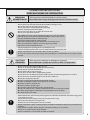 3
3
-
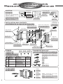 4
4
-
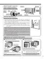 5
5
-
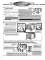 6
6
-
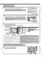 7
7
-
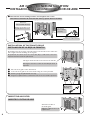 8
8
-
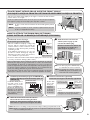 9
9
-
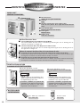 10
10
-
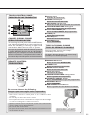 11
11
-
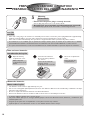 12
12
-
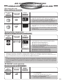 13
13
-
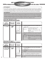 14
14
-
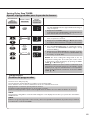 15
15
-
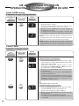 16
16
-
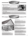 17
17
-
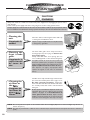 18
18
-
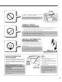 19
19
-
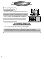 20
20
-
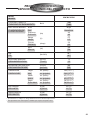 21
21
-
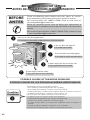 22
22
-
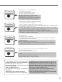 23
23
-
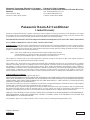 24
24


Panasonic CW-XC82YU Manual de usuario
- Tipo
- Manual de usuario
en otros idiomas
- English: Panasonic CW-XC82YU User manual
Artículos relacionados
-
Panasonic CW-XC80YU Manual de usuario
-
-
-
-
-
-
-
Panasonic HQ2081QH Instrucciones de operación
-
-