Yamaha MTX5 El manual del propietario
- Categoría
- Equipo musical
- Tipo
- El manual del propietario
Este manual también es adecuado para

EN
Owner’s Manual

MTX5-D Owner’s Manual
2
The above warning is located on the top of the unit.
Explanation of Graphical Symbols
The lightning flash with arrowhead symbol
within an equilateral triangle is intended to
alert the user to the presence of uninsulated
“dangerous voltage” within the product’s
enclosure that may be of sufficient magnitude
to constitute a risk of electric shock to per-
sons.
The exclamation point within an equilateral
triangle is intended to alert the user to the
presence of important operating and mainte-
nance (servicing) instructions in the literature
accompanying the product.
IMPORTANT SAFETY INSTRUCTIONS
1 Read these instructions.
2 Keep these instructions.
3 Heed all warnings.
4 Follow all instructions.
5 Do not use this apparatus near water.
6 Clean only with dry cloth.
7 Do not block any ventilation openings. Install in
accordance with the manufacturer’s instructions.
8 Do not install near any heat sources such as radia-
tors, heat registers, stoves, or other apparatus
(including amplifiers) that produce heat.
9 Do not defeat the safety purpose of the polarized or
grounding-type plug. A polarized plug has two blades
with one wider than the other. A grounding type plug
has two blades and a third grounding prong. The
wide blade or the third prong are provided for your
safety. If the provided plug does not fit into your out-
let, consult an electrician for replacement of the
obsolete outlet.
10 Protect the power cord from being walked on or
pinched particularly at plugs, convenience recepta-
cles, and the point where they exit from the appara-
tus.
11 Only use attachments/accessories specified by the
manufacturer.
12 Use only with the cart, stand,
tripod, bracket, or table speci-
fied by the manufacturer, or
sold with the apparatus. When
a cart is used, use caution
when moving the cart/appara-
tus combination to avoid injury
from tip-over.
13 Unplug this apparatus during lightning storms or
when unused for long periods of time.
14 Refer all servicing to qualified service personnel. Ser-
vicing is required when the apparatus has been dam-
aged in any way, such as power-supply cord or plug
is damaged, liquid has been spilled or objects have
fallen into the apparatus, the apparatus has been
exposed to rain or moisture, does not operate nor-
mally, or has been dropped.
(UL60065_03)
CAUTION: TO REDUCE THE RISK OF
ELECTRIC SHOCK, DO NOT REMOVE
COVER (OR BACK). NO USER-SERVICEABLE
PARTS INSIDE. REFER SERVICING TO
QUALIFIED SERVICE PERSONNEL.
CAUTION
RISK OF ELECTRIC SHOCK
DO NOT OPEN
WARNING
TO REDUCE THE RISK OF FIRE OR ELECTRIC SHOCK, DO NOT EXPOSE THIS APPARATUS TO RAIN OR MOISTURE.

MTX5-D Owner’s Manual
3
1. IMPORTANT NOTICE: DO NOT MODIFY THIS UNIT!
This product, when installed as indicated in the instructions
contained in this manual, meets FCC requirements. Modifi-
cations not expressly approved by Yamaha may void your
authority, granted by the FCC, to use the product.
2. IMPORTANT: When connecting this product to accessories
and/or another product use only high quality shielded cables.
Cable/s supplied with this product MUST be used. Follow all
installation instructions. Failure to follow instructions could
void your FCC authorization to use this product in the USA.
3. NOTE: This product has been tested and found to comply
with the requirements listed in FCC Regulations, Part 15 for
Class “B” digital devices. Compliance with these require-
ments provides a reasonable level of assurance that your
use of this product in a residential environment will not result
in harmful interference with other electronic devices. This
equipment generates/uses radio frequencies and, if not
installed and used according to the instructions found in the
users manual, may cause interference harmful to the opera-
tion of other electronic devices. Compliance with FCC regu-
lations does not guarantee that interference will not occur in
all installations. If this product is found to be the source of
interference, which can be determined by turning the unit
“OFF” and “ON”, please try to eliminate the problem by using
one of the following measures:
Relocate either this product or the device that is being
affected by the interference.
Utilize power outlets that are on different branch (circuit
breaker or fuse) circuits or install AC line filter/s.
In the case of radio or TV interference, relocate/reorient the
antenna. If the antenna lead-in is 300 ohm ribbon lead,
change the lead-in to co-axial type cable.
If these corrective measures do not produce satisfactory
results, please contact the local retailer authorized to distrib-
ute this type of product. If you can not locate the appropriate
retailer, please contact Yamaha Corporation of America,
Electronic Service Division, 6600 Orangethorpe Ave, Buena
Park, CA90620
The above statements apply ONLY to those products distrib-
uted by Yamaha Corporation of America or its subsidiaries.
* This applies only to products distributed by YAMAHA CORPORATION OF AMERICA. (class B)
FCC INFORMATION (U.S.A.)
COMPLIANCE INFORMATION STATEMENT
(DECLARATION OF CONFORMITY PROCEDURE)
Responsible Party : Yamaha Corporation of America
Address : 6600 Orangethorpe Ave., Buena Park,
Calif. 90620
Telephone : 714-522-9011
Type of Equipment : Matrix Processor
Model Name : MTX5-D
This device complies with Part 15 of the FCC Rules.
Operation is subject to the following two conditions:
1) this device may not cause harmful interference, and
2) this device must accept any interference received including
interference that may cause undesired operation.
See user manual instructions if interference to radio reception
is suspected.
* This applies only to products distributed by
YAMAHA CORPORATION OF AMERICA.
(FCC DoC)
IMPORTANT NOTICE FOR THE UNITED KINGDOM
Connecting the Plug and Cord
WARNING: THIS APPARATUS MUST BE EARTHED IMPOR-
TANT. The wires in this mains lead are coloured in accordance
with the following code:
GREEN-AND-YELLOW : EARTH
BLUE : NEUTRAL
BROWN : LIVE
As the colours of the wires in the mains lead of this apparatus
may not correspond with the coloured markings identifying the
terminals in your plug proceed as follows:
The wire which is coloured GREEN-and-YELLOW must be
connected to the terminal in the plug which is marked by the
letter E or by the safety earth symbol or colored GREEN or
GREEN-and-YELLOW.
The wire which is coloured BLUE must be connected to the
terminal which is marked with the letter N or coloured BLACK.
The wire which is coloured BROWN must be connected to the
terminal which is marked with the letter L or coloured RED.
(3 wires)
ADVARSEL!
Lithiumbatteri—Eksplosionsfare ved fejlagtig håndtering.
Udskiftning må kun ske med batteri af samme fabrikat og type.
Levér det brugte batteri tilbage til leverandoren.
VARNING
Explosionsfara vid felaktigt batteribyte. Använd samma batteri-
typ eller en ekvivalent typ som rekommenderas av apparattill-
verkaren. Kassera använt batteri enligt fabrikantens
instruktion.
VAROITUS
Paristo voi räjähtää, jos se on virheellisesti asennettu. Vaihda
paristo ainoastaan laitevalmistajan suosittelemaan tyyppiin.
Hävitä käytetty paristo valmistajan ohjeiden mukaisesti.
(lithium caution)
NEDERLAND / THE NETHERLANDS
• Dit apparaat bevat een lithium batterij voor geheugen back-up.
• This apparatus contains a lithium battery for memory back-up.
• Raadpleeg uw leverancier over de verwijdering van de bat-
terij op het moment dat u het apparaat ann het einde van de
levensduur of gelieve dan contact op te nemen met de verte-
genwoordiging van Yamaha in uw land.
• For the removal of the battery at the moment of the disposal
at the end of life please consult your retailer or Yamaha rep-
resentative office in your country.
• Gooi de batterij niet weg, maar lever hem in als KCA.
• Do not throw away the battery. Instead, hand it in as small
chemical waste.
(lithium disposal)
This product contains a battery that contains perchlorate material.
Perchlorate Material—special handling may apply,
See www.dtsc.ca.gov/hazardouswaste/perchlorate.
* This applies only to products distributed
by YAMAHA CORPORATION OF AMERICA.
이 기기는 가정용(B급) 전자파적합기기로서 주로 가정에서
사용하는 것을 목적으로 하며, 모든 지역에서 사용할 수 있습
니다.
(class b korea)(Perchlorate)

MTX5-D Owner’s Manual
4
PRECAUTIONS
PLEASE READ CAREFULLY BEFORE PROCEEDING
* Please keep this manual in a safe place for future reference.
WARNING
Always follow the basic precautions listed below to avoid the possibility of serious injury or even death from
electrical shock, short-circuiting, damages, fire or other hazards. These precautions include, but are not limited
to, the following:
• Do not place the power cord near heat sources such as heaters or radiators, and do not
excessively bend or otherwise damage the cord, place heavy objects on it, or place it in
a position where anyone could walk on, trip over, or roll anything over it.
• Only use the voltage specified as correct for the device. The required voltage is printed
on the name plate of the device.
• Use only the supplied power cord/plug.
If you intend to use the device in an area other than in the one you purchased, the
included power cord may not be compatible. Please check with your Yamaha dealer.
• Check the electric plug periodically and remove any dirt or dust which may have
accumulated on it.
• Be sure to connect to an appropriate outlet with a protective grounding connection.
Improper grounding can result in electrical shock.
• This device contains no user-serviceable parts. Do not open the device or attempt to
disassemble the internal parts or modify them in any way. If it should appear to be
malfunctioning, discontinue use immediately and have it inspected by qualified
Yamaha service personnel.
• Do not expose the device to rain, use it near water or in damp or wet conditions, or
place on it any containers (such as vases, bottles or glasses) containing liquids which
might spill into any openings. If any liquid such as water seeps into the device, turn off
the power immediately and unplug the power cord from the AC outlet. Then have the
device inspected by qualified Yamaha service personnel.
• Never insert or remove an electric plug with wet hands.
• Do not put burning items, such as candles, on the unit. A burning item may fall over
and cause a fire.
• When one of the following problems occur, immediately turn off the power switch and
disconnect the electric plug from the outlet. Then have the device inspected by Yamaha
service personnel.
- The power cord or plug becomes frayed or damaged.
- It emits unusual smells or smoke.
- Some object has been dropped into the instrument.
- There is a sudden loss of sound during use of the device.
• If this device should be dropped or damaged, immediately turn off the power switch,
disconnect the electric plug from the outlet, and have the device inspected by qualified
Yamaha service personnel.
CAUTION
Always follow the basic precautions listed below to avoid the possibility of physical injury to you or others, or
damage to the device or other property. These precautions include, but are not limited to, the following:
• When removing the electric plug from the device or an outlet, always hold the plug
itself and not the cord. Pulling by the cord can damage it.
• Remove the electric plug from the outlet when the device is not to be used for extended
periods of time, or during electrical storms.
• Do not place the device in an unstable position where it might accidentally fall over.
• Do not block the vents. This device has ventilation holes at the front, side, and rear to
prevent the internal temperature from becoming too high. In particular, do not place the
device on its side or upside down. Inadequate ventilation can result in overheating,
possibly causing damage to the device(s), or even fire.
• Do not place the device in a location where it may come into contact with corrosive
gases or salt air. Doing so may result in malfunction.
• Before moving the device, remove all connected cables.
• When setting up the device, make sure that the AC outlet you are using is easily
accessible. If some trouble or malfunction occurs, immediately turn off the power
switch and disconnect the plug from the outlet. Even when the power switch is turned
off, electricity is still flowing to the product at the minimum level. When you are not
using the product for a long time, make sure to unplug the power cord from the wall AC
outlet.
• If the device is mounted in an EIA standard rack, carefully read the section “Precautions
for rackmounting” on page 7. Inadequate ventilation can result in overheating, possibly
causing damage to the device(s), malfunction, or even fire.
• Keep device away from the reach of children.
• Before connecting the device to other devices, turn off the power for all devices. Before
turning the power on or off for all devices, set all volume levels to minimum.
• Remove the power plug from the AC outlet when cleaning the device.
• Do not insert your fingers or hands in any gaps or openings on the device (vents).
• Avoid inserting or dropping foreign objects (paper, plastic, metal, etc.) into any gaps or
openings on the device (vents). If this happens, turn off the power immediately and
unplug the power cord from the AC outlet. Then have the device inspected by qualified
Yamaha service personnel.
• Do not rest your weight on the device or place heavy objects on it, and avoid use
excessive force on the buttons, switches or connectors.
• Do not use the device/speakers for a long period of time at a high or uncomfortable
volume level, since this can cause permanent hearing loss. If you experience any
hearing loss or ringing in the ears, consult a physician.
• This device has a built-in backup battery. When you unplug the power cord from the AC
outlet, the internal data is retained. However, if the backup battery fully discharges, this
data will be lost. When the backup battery is running low, the [PRESET] display
indicates “12.” In this case, immediately save the data to external device such as a
computer, then have qualified Yamaha service personnel replace the backup battery.
Always turn the power off when the device is not in use.
Power supply/Power cord
Do not open
Water warning
Fire warning
If you notice any abnormality
Power supply/Power cord
Location
Connections
Yamaha cannot be held responsible for damage caused by improper use or
modifications to the device, or data that is lost or destroyed.
Maintenance
Handling caution
Backup battery
PA_en_1 1/1

MTX5-D Owner’s Manual
5
NOTICE
To avoid the possibility of malfunction/ damage to the product,
damage to data, or damage to other property, follow the notices
below.
Handling and Maintenance
• Do not use the device in the vicinity of a TV, radio, stereo
equipment, mobile phone, or other electric devices. Other-
wise, the device, TV, or radio may generate noise.
• Do not expose the device to excessive dust or vibration, or
extreme cold or heat (such as in direct sunlight, near a
heater, or in a car during the day), in order to prevent the
possibility of panel disfiguration, unstable operation, or dam-
age to the internal components.
• Do not place vinyl, plastic or rubber objects on the device,
since this might discolor the panel.
• When cleaning the device, use a dry and soft cloth. Do not
use paint thinners, solvents, cleaning fluids, or chemical-
impregnated wiping cloths.
• Condensation can occur in the device due to rapid, drastic
changes in ambient temperature—when the device is moved
from one location to another, or air conditioning is turned on
or off, for example. Using the device while condensation is
present can cause damage. If there is reason to believe that
condensation might have occurred, leave the device for sev-
eral hours without turning on the power until the condensa-
tion has completely dried out.
• When turning on the AC power in your audio system, always
turn on the power amplifier LAST, to avoid speaker damage.
When turning the power off, the power amplifier should be
turned off FIRST for the same reason.
Saving data
This device has a built-in backup battery that maintains data in
internal memory even when the device’s power is switched off.
The backup battery will eventually become depleted, however,
and when that happens the contents of the internal memory will
be lost.* To prevent loss of data be sure to replace the backup
battery before it becomes fully depleted. If the backup battery
runs low, alert number “12.” will appear in the [PRESET] display
either while the unit is starting up. If this occurs, do not turn off the
power, but immediately save the data to a computer or other
external storage device, and then have qualified Yamaha service
personnel replace the backup battery. The average life of the
internal backup battery is approximately five years, depending on
operating conditions.
* Data items maintained in the internal memory by the backup
battery are as follows:
• Contents of the current preset and the preset number
• Parameters specific to the unit (e.g., configuration data)
• Current parameters for peripheral devices within the same
system
• Event log
Data items other than those described above are stored in
memory that does not require backup power, and will be
retained even if the backup battery fails.
Information
About this manual
• The illustrations as shown in this manual are for instructional
purposes only, and may appear somewhat different from
those on your device.
• Ethernet is a trademark of Xerox Corporation.
• Windows is a registered trademark of Microsoft® Corpora-
tion in the United States and other countries.
• SDHC Logo and SD Logo are trademarks of SD-3C, LLC.
• The company names and product names in this manual are
the trademarks or registered trademarks of their respective
companies.
• MPEG Layer-3 audio coding technology licensed from
Fraunhofer IIS and Thomson.
(weee_eu_en_02)
Information for users on collection and disposal of old equipment:
This symbol on the products, packaging, and/or accompanying documents means that used electrical and electronic
products should not be mixed with general household waste.
For proper treatment, recovery and recycling of old products, please take them to applicable collection points, in accor-
dance with your national legislation.
By disposing of these products correctly, you will help to save valuable resources and prevent any potential negative
effects on human health and the environment which could otherwise arise from inappropriate waste handling.
For more information about collection and recycling of old products, please contact your local municipality, your waste
disposal service or the point of sale where you purchased the items.
For business users in the European Union:
If you wish to discard electrical and electronic equipment, please contact your dealer or supplier for further information.
Information on Disposal in other Countries outside the European Union:
This symbol is only valid in the European Union. If you wish to discard these items, please contact your local authorities
or dealer and ask for the correct method of disposal.

MTX5-D Owner’s Manual
6
Contents
PRECAUTIONS................................................................................................................4
Getting Started................................................................................................................7
Included items (please check) ................................................................................................ 7
Firmware versions................................................................................................................... 7
Precautions for rackmounting.................................................................................................. 7
Introducing the MTX5-D .................................................................................................8
Features.................................................................................................................................. 8
About MTX-MRX Editor .......................................................................................................... 8
Using the PDF manual............................................................................................................8
Controls and Connectors ..............................................................................................9
Front Panel.............................................................................................................................. 9
Rear Panel ............................................................................................................................ 10
Euroblock plug connection............................................................................................. 13
Installing an option card................................................................................................. 14
About Dante ..................................................................................................................15
About connections ................................................................................................................ 15
Daisy chain network ...................................................................................................... 15
Star network .................................................................................................................. 15
About redundant networks............................................................................................. 16
About Dante Controller .................................................................................................. 16
Quick Guide ..................................................................................................................17
Preparations.......................................................................................................................... 17
On-site work (Installation and wiring).................................................................................... 18
On-site work (Settings in MTX-MRX Editor).......................................................................... 19
Various Procedures......................................................................................................20
Recalling (switching) presets ................................................................................................ 20
Switching presets from the MTX5-D .............................................................................. 20
Setting the clock.................................................................................................................... 20
Using the scheduler .............................................................................................................. 20
Connecting via the [GPI] connector ...................................................................................... 21
Using the MTX5-D to play audio files saved on an SD memory card ................................... 22
Inserting an SD memory card........................................................................................ 22
Removing the SD memory card..................................................................................... 22
Initializing the MTX5-D.......................................................................................................... 22
Appendix .......................................................................................................................24
Troubleshooting..................................................................................................................... 24
Messages ............................................................................................................................. 26
Alert list................................................................................................................................. 27
Specifications........................................................................................................................ 29
Input/Output Characteristics ................................................................................................. 30
Dimensions ........................................................................................................................... 30
Block Diagram....................................................................................................................... 31
Index ..................................................................................................................................... 32

MTX5-D Owner’s Manual
7
Getting Started
Thank you for purchasing the Yamaha Matrix Processor MTX5-D. This manual will help you take
full advantage of the superior functionality offered by the MTX5-D. After you have read the manual,
keep it in a safe place for reference when needed.
• MTX5-D Owner’s Manual (this document)
• Power cable
• Euroblock plugs (16-pin, 3.50mm pitch) (2)
• Euroblock plugs (3-pin, with tab, 5.08mm pitch) (16)
• Cable ties (16)
Use MTX-MRX Editor to update the firmware of the MTX5-D
or check the firmware version. For details on operation, refer to
the MTX-MRX Editor User Guide.
Download the latest firmware from the “Downloads” page on
the following website.
http://download.yamaha.com/
This device is guaranteed to operate at an ambient temperature
of 0 to 40 °C. If this device is mounted in an EIA rack together
with other devices, heat from the various devices may cause the
temperature inside the rack to rise, rendering this device unable
to perform to its full potential. To ensure that heat does not
accumulate inside this device, please ensure that the following
conditions are met when rack-mounting it.
• If you plan to mount this device together with devices that
tend to generate heat, such as power amps other than XMV
series products, allow 1U or more of vacant space between
this device and other devices. Also attach ventilation panels
in this space or leave them open to ensure sufficient ventila-
tion.
• Leave the back of the rack open, and allow at least 10 cm of
space between the rack and the wall or ceiling to ensure suf-
ficient ventilation. If the back of the rack cannot be left open,
provide forced air cooling for the rack, for example by
installing a commercially available fan kit. If you install a
fan kit, leaving the back of the rack closed may provide more
effective cooling. For details, refer to the owner’s manual
provided with the rack or fan kit.
Included items (please check) Firmware versions
Precautions for rackmounting

MTX5-D Owner’s Manual
8
Introducing the MTX5-D
• A signal processor suitable for small or mid-sized
installed systems
The MTX5-D is a signal processor suitable for small or mid-
sized systems such as retail establishments or banquet halls. In
addition to a 34 ch. x 16 ch. matrix mixer, it provides 3-band
parametric EQ, compressor/gate, auto gain control, eight pri-
ority duckers, and eight feedback suppressors. For the output
stages, it provides numerous high-performance high-quality
processors, such as 4-band parametric EQ, delay, and speaker
processor.
• Use Dante to construct small-scale or large-scale
systems
Audinate’s “Dante” audio network protocol is used to transfer
audio signals over extended distances via Ethernet cable.
MTX-MRX Editor makes it easy to specify the audio routing
between the MTX5-D and Dante models of the XMV.
• Newly-developed “YDIF” digital audio transmis-
sion format
“YDIF” is a digital audio transmission format that uses Ether-
net cable to send and receive up to 16 channels of audio and
word clock. You can use Ethernet cables up to 30 meters long
to easily make connections between devices.
• Slot for installing a Mini-YGDAI card
A separately sold Mini-YGDAI card can be installed to flexi-
bly add analog inputs/outputs or digital inputs/outputs.
• Versatile input/output and SD memory card slot
In addition to eight high-quality monaural mic/line inputs and
two stereo line inputs, digital input/output via “YDIF” or
“Dante” allows a maximum total of 30 simultaneous input
channels. An SD memory card slot for playback is also pro-
vided; allowing MP3/WAV audio files saved on the SD mem-
ory card to be played back. In addition to eight channels of
analog monaural output, up to 16 channels of digital output
can be obtained via “YDIF” or “Dante.”
• Support for external controls
By connecting a “DCP” series dedicated wall-mounted control
panel to the [DCP] connector, you can easily control the vol-
ume of multiple zones or switch presets. Daisy-chain connec-
tion via Ethernet cable allows up to eight “DCP” series control
panels to be connected. The total cable length from the
MTX5-D to the farthest control panel can be up to 200 meters,
and power is also supplied, allowing you to place the control
panel in the ideal location for the room. A NETWORK con-
nector and [GPI] connector are also provided for controlling
the unit from an AMX/Crestron or other touch panel device.
• Dedicated “MTX-MRX Editor” application soft-
ware for designing the entire system
“MTX-MRX Editor” is application software for editing the
parameters of the MTX5-D. Using operating screens that
reflect the workflow of designing the installation, this soft-
ware makes it easy to design a system and make (or adjust)
settings. A speaker library of Yamaha-manufactured speakers
is also built-in, making it easy to choose settings that will
maximize the performance of your speakers.
• iPhone app support
A dedicated iPhone app makes it easy to control the volume
and manage presets in the same way as when using the dedi-
cated wall-mounted control panel. You can use your iPhone/
iPod touch to easily control the sound system of a retail loca-
tion or a banquet hall.
MTX-MRX Editor is software for the Windows operating sys-
tem that allows unified construction and control of systems that
use the MTX series.
MTX-MRX Editor and the MTX-MRX Editor User Guide can
be downloaded from the following website.
http://download.yamaha.com/
For details on installing MTX-MRX Editor and connecting the
MTX5-D to your computer, refer to the “MTX Setup Manual.”
The MTX-MRX Editor User Guide is an electronic file in PDF
format. You can read this book on a computer. Use Adobe®
Reader® to read this book on screen, search for words very
quickly, print specific pages, or click links to display sections of
special interest. The ability to search for words, or to follow
links directly to relevant sections in the document, are helpful
attributes of this electronic file format. We encourage you to
take advantage of these benefits.
You can download the latest Adobe Reader application from the
website listed below.
http://www.adobe.com/
Features About MTX-MRX Editor
Using the PDF manual

MTX5-D Owner’s Manual
9
Controls and Connectors
q SD memory card slot
You can insert an SD memory card here. Music or sound
effects can be played back from an SD memory card contain-
ing audio files (MP3 files and WAV files). Before you insert
an SD memory card into the slot, or remove an SD memory
card from the slot, remove the slot cover.
For details on SD memory card handling, refer to page 22.
For details on how to play back audio files, refer to the
MTX-MRX Editor User Guide.
w [INPUT PEAK] indicators 1–8
These indicators will light red when the input level of the
corresponding INPUT channel is -3 dBFS or higher.
e [INPUT SIGNAL] indicators 1–8
These indicators will light green when the input level of the
corresponding INPUT channel is -40 dBFS or higher.
r [OUTPUT SIGNAL] indicators 1–8
These indicators will light green when the output level of the
corresponding OUTPUT channel is -40 dBFS or higher.
t [PRESET] display
This display usually shows the preset number. It can also
show the UNIT ID, alert number, or a message.
y [s]/[t] buttons
Use these buttons to change the preset number or alert num-
ber shown in the above [PRESET] display.
u [ENTER] button
Use this button to confirm the item shown in the above
[PRESET] display.
When an alert number is shown, pressing this button will
return to the preset number display.
i [ALERT] indicator
When an alert occurs, the [PRESET] display will indicate
the alert number and this indicator will flash red.
o [PRIMARY]/[SECONDARY] indicators
These indicators show the communication status of the
Dante [PRIMARY] and [SECONDARY] connectors.
They flash fast if the Ethernet cables are connected properly.
!0 [SYNC] indicators
This indicator shows the operational status of the Dante net-
work.
If the green indicator lights, the unit is operating as a word
clock slave and synching to the word clock.
If the green indicator flashes, the unit is not functioning
properly. In this case, refer to the “Messages” section (see
page 26).
If the orange indicator lights or flashes, refer to the “Mes-
sages” section.
!1 [POWER] indicator
This indicator will light when this device is powered-on.
!2 [YDIF] indicator
This indicator will light green if the rear panel [YDIF IN]
connector (page 12) is correctly connected to the [YDIF
OUT] connector of another device.
!3 [SCHEDULER] indicator
This indicator will light yellow if an even has been specified
in the scheduler (page 20), and will start flashing one minute
before the event.
!4 [SD/ACT] indicator
This indicator will light yellow if an SD memory card is
inserted in the SD memory card slot (q) and has been
detected correctly. It will flash while the SD memory card is
being accessed.
!5 Power switch
This is the power switch. The power is on if the switch is in
the position. The power is off if the switch is in the
position.
Front Panel
88
!5yu i !1 !2qwet
r!3!4!0o
NOTE
• Do not cycle the power switch in rapid succession. Wait at
least 6 seconds before turning the power switch on after it
has been turned off. Failing to observe this precaution
may cause malfunctions.
• Even when the power switch is turned off, a small amount
of current is flowing through the unit. If you plan not to use
the unit for a long period of time, remove the power cable
from the AC outlet.

Controls and Connectors
MTX5-D Owner’s Manual
10
q AC IN connector
Use the included power cord to supply power to this connec-
tor. First, connect the power cord to this device, and then
insert the power cord plug into the AC outlet.
w Ground screw
The supplied power cord has a three-prong plug that will
ground the device when plugged into an appropriately
grounded three-prong type AC mains outlet. In some cases,
you may be able to reduce hum or interference by also con-
necting this screw to ground.
e Cooling vent
The MTX5-D contains a cooling fan. The cooling air is
exhausted here, so please be careful not to block this vent.
r [GPI] connector
This Euroblock connector allows input and output of control
signals via GPI (General Purpose Interface).
The MTX5-D provides sixteen ports of analog/digital input,
one port of digital input, and eight ports of output. The [IN]-
1–15 terminals detect voltage changes from 0V to 5V. The
[IN]-16 terminal alone supports +24V input; voltages in the
range of 2.5–24V are detected as High, and voltages below
2.5V are detected as Low. The [OUT]-1–8 terminals are
open collector outputs; they will change between open or
closed (Ground). The +5VDC terminals has an output volt-
age of 5V. Use the included Euroblock plugs to make con-
nections (see “Euroblock plug connection” on page 13 for
details).
For details on connections and usage, refer to “Connecting
via the [GPI] connector” on page 21.
t [RS-232C] connector
This 9-pin D-SUB connector allows connection to an RS-
232C compatible controller such as those from AMX or Cre-
stron.
y [UNIT ID] rotary switch
When multiple devices are connected within the same net-
work, this switch specifies the UNIT ID by which MTX5-D
devices are individually distinguished.
DIP switches 1 and 2 described below specify the upper
digit, and this rotary switch specifies the lower digit,
together allowing you to set the UNIT ID to one of 63 possi-
bilities in the range of 01 to 3F.
u DIP switches
These switches enable you to specify the settings related to
the startup operation of the unit.
Refer to the following for details.
Rear Panel
qyu!0io !1 !2
w!3
r
e
!4
t
NOTE
The MTX5-D has some connectors that are shaped identically
but have a completely different function (e.g., [DCP] connector,
Dante [PRIMARY]/[SECONDARY] connectors, [YDIF] connec-
tors). Make the appropriate connections as instructed by the
explanation for each connector. Otherwise, you risk damaging
your equipment.
CAUTION
Do not input a voltage higher than 5V to the [IN]-1–15
terminals. Doing so may damage your equipment.
NOTE
• Do not use a UNIT ID of “00” (DIP switches 1 and 2 OFF
and the rotary switch at 0).
• You’ll need to restart the device after changing the setting
of the [UNIT ID] rotary switch.
NOTE
Set the DIP switches while the power to the unit is turned
OFF. Otherwise, the setting will not be effective.
Switch Status
Represent a status with switch toggled up.
Represent a status with switch toggled
down.

Controls and Connectors
MTX5-D Owner’s Manual
11
Switches 1–2 (UNIT ID)
These switches specify the upper digit and the above-
mentioned [UNIT ID] rotary switch specifies the lower
digit, together allowing you to specify one of 63 different
UNIT ID numbers in a range from 01 to 3F.
Switch 3
Not used. Turn it off (up) at any time.
Switch 4 (SECONDARY PORT)
This switch setting determines whether the rear-panel
Dante [SECONDARY] connector will be used for a daisy
chain or redundant network.
With the [DAISY CHAIN] setting, you can connect mul-
tiple Dante-enabled network devices in a daisy chain
without using a network switch. Refer to “Daisy chain
network” in the “About connections” section (see page
15) for more information about daisy chain connections.
With the Dante [REDUNDANT] setting, the Dante [PRI-
MARY] connector will be used for primary connections,
and the Dante [SECONDARY] connector will be used for
secondary (backup) connections. If the unit is unable to
transmit signals through the Dante [PRIMARY] connec-
tor for some reason (e.g., due to damage or accidental
removal of the cable, or a failed network switch), the
Dante [SECONDARY] connector will automatically take
over communications and functions on the redundant net-
work. Refer to “About redundant networks” in the
“About connections” section (see page 15) for more
information on redundant networks.
Switch 5 (PANEL LOCK)
This switch locks the front panel controls. Use this if you
want to prevent accidental operation from the front panel.
Switch 6 (IP SETTING)
This switch specifies how the MTX5-D’s IP address will
be specified.
Switches 7–8 (START UP MODE)
These specify whether the MTX5-D will be initialized
when it is powered-on.
i [DCP] connector
Use this connector to daisy-chain separately sold control
panels such as the DCP1V4S to control the MTX5-D. Use a
CAT5e or better Ethernet straight cable that has all eight pins
connected.
Up to eight control panels can be connected to one MTX5-D.
The total length of the cables from the MTX5-D to the last
control panel must not exceed 200 meters.
Switch position
Option Functions
UNIT ID is
“0x”
The [UNIT ID] rotary switch
will have a setting range of
01 through 0F.
UNIT ID is
“1x”
The [UNIT ID] rotary switch
will have a setting range of
10 through 1F.
UNIT ID is
“2x”
The [UNIT ID] rotary switch
will have a setting range of
20 through 2F.
UNIT ID is
“3x”
The [UNIT ID] rotary switch
will have a setting range of
30 through 3F.
NOTE
Do not use a UNIT ID of “00” (DIP switches 1 and 2 OFF
and the rotary switch at 0).
Switch position
Option Functions
DAISY
CHAIN
The Dante [SECONDARY]
connector is used for a
daisy chain connection. It
can be connected in a daisy
chain by connecting to
Dante [PRIMARY] connec-
tor of the next device.
REDUNDANT
The Dante [SECONDARY]
connector is used for a
redundant network. It will
function as backup connec-
tion, independent of the net-
work to which the Dante
[PRIMARY] connector is
connected.
Switch position
Option Functions
UNLOCK
The front panel controls will
be available for operation.
LOCK
The front panel controls will
be locked, and will be inop-
erable. The device can be
operated from a computer
or an external controller.
Switch position
Option Functions
UNIT ID
The IP address will be
specified according to the
UNIT ID, and will be
192.168.0.(UNIT ID).
PC
The IP address will be
determined by the settings
of MTX-MRX Editor. (See
“MTX-MRX Editor User
Guide.”)
NOTE
You must set this to the “UNIT ID” position the first time
you connect this device to a computer after purchase. If
you subsequently want to specify the IP address instead
of using the UNIT ID, specify the IP address from MTX-
MRX Editor and then switch this setting to the “PC” posi-
tion.
Switch position
Option Functions
RESUME
This is the normal operating
mode. When you power-on
the MTX5-D, it will start up
in the same state in which it
was when the power was
turned off.
INIT.
(INITIALIZE)
Initializes the MTX5-D,
returning it to the factory-set
state (page 22).
CAUTION
• Do not connect a control panel to any connector
other than the MTX5-D’s [DCP] connector. Since the
control panel is not electrically compatible, such con-
nections may cause fire or malfunction.
• Never connect any device to the [DCP] connector
other than the separately sold DCP or other control
panel. Doing so may damage the other device or this
device.

Controls and Connectors
MTX5-D Owner’s Manual
12
o [YDIF] connectors
These connectors are used to make a ring connection with
the devices that comprise the MTX/MRX system, allowing
digital audio signals to be transmitted and received. Use
CAT5e or better Ethernet STP cables (shielded twisted pair
cables) that have all eight pins connected in a straight con-
nection. The maximum cable length between devices is 30
meters, and you can connect up to eight devices that are
equipped with the [YDIF] connectors. For details, refer to
the MTX-MRX Editor User Guide.
!0 POWER IN +24V DC
Support for this connector is planned for the future.
!1 Dante [PRIMARY]/[SECONDARY] connectors
This is an RJ45 connector used to connect the unit to a com-
puter or a Dante device such as the XMV4280-D via an
Ethernet cable (CAT5e or better is recommended).
If DIP switch 4 on the rear panel is set upward (to DAISY
CHAIN), audio signals coming into one of these connectors
will be output from the other. Refer to “Daisy chain net-
work” in the “About connections” section (see page 15) for
more information on daisy chain connections.
If DIP switch 4 on the rear panel is set downward (to
REDUNDANT), the Dante [PRIMARY] connector will be
used for primary connection, and the Dante [SECONDARY]
connector will be used for secondary (backup) connection. If
the unit is unable to transmit signals through the Dante [PRI-
MARY] connector for some reason (e.g., due to damage or
accidental removal of the cable, or a failed network switch),
the Dante [SECONDARY] connector will automatically take
over the connection. Refer to “About redundant networks” in
the “About connections” section (see page 16) for more
information on redundant networks.
The connected computer is used mainly with the dedicated
“MTX-MRX Editor” application program for the purpose of
setting up or controlling the MTX/MRX system.
!2 [ST IN] connectors
These are unbalanced RCA phono jacks for inputting analog
audio signals from a CD player or other device.
!3 Slot
This slot allows a separately sold Mini-YGDAI I/O card to
be installed.
!4 [INPUT]/[OUTPUT] connectors
These are balanced input/output connectors for analog audio
input and output. Connect line level devices or microphones
to the [INPUT] connectors, and line level devices to the
[OUTPUT] connectors. The [INPUT] connectors provide
head amps, and can also provide +48V phantom power.
MTX-MRX Editor is used to specify the gain of the internal
head amps and to turn the phantom power on/off.
Use the included Euroblock plugs to make connections (see
“Euroblock plug connection” on page 13 for details).
NOTE
Using a Mini-YGDAI card for an external word clock may
cause noise in system configurations with multiple YDIF
connections. In such cases, we recommend using a differ-
ent word clock source, such as Dante or YDIF.
NOTE
• Since Dante-compatible equipment made by Yamaha
such as the MTX5-D contains a built-in network switch,
the number of hops will be two or more. For this reason,
the 0.15 msec Latency setting in Dante Controller will be
grayed-out and unavailable.
• Use STP (shielded twisted pair) cable to prevent electro-
magnetic interference.
NOTE
Adjusting the internal head amp gain between +17 dB and
+18 dB will internally turn PAD on/off. Noise may occur if
there is an impedance difference between the Hot and Cold
of a device connected to the [INPUT] connectors while
phantom power is being used.

Controls and Connectors
MTX5-D Owner’s Manual
13
Euroblock plug connection
Use the included Euroblock plugs when making connections
to the [INPUT]/[OUTPUT] connectors and [GPI] connector.
1. Loosen the terminal screws.
2. Insert cables.
3. Securely tighten the terminal screws.
Pull the cables (not too strongly) to confirm that they are
securely connected.
4. For the Euroblock plugs (3-pin) of the
[INPUT]/[OUTPUT] connectors, use the
included cable ties to fasten the cable to the
tab.
Cable preparation
• Use stranded wire for Euroblock connections, and
strip the wire as shown in the illustration. With a
Euroblock connection, the stranded wire may be
prone to breakage because of metal fatigue due to
the weight of the cable or due to vibration. Cables
connected to the [INPUT]/[OUTPUT] connectors
should be fastened to the tab of the Euroblock plug
(3-pin) using the included cable ties (see illustration
at right). When rack-mounting the device, use a lac-
ing bar when possible to bundle and secure the
cable.
• If cables will be frequently connected and discon-
nected, as in the case of a portable system, we rec-
ommend that you use ferrules with insulation
sleeves. Use a ferrule whose conductor portion has
an external diameter of 1.6 mm or less (1.3 mm or
less for the [GPI] connector) and a length of approx-
imately 7 mm (approximately 5 mm for the [GPI]
connector) such as the AI 0,5 - 6 WH made by the
Phoenix Contact corporation.
approx. 7 mm
(approx. 5 mm for
the GPI connector)
approx. 20 mm
NOTE
Do not tin (plate with solder) the stranded wire.
1.6 mm or less
(1.3 mm for the GPI connector)
approx. 7 mm
(approx. 5 mm for
the GPI connector)
NOTE
Use a slotted screwdriver with a blade width of 2 mm or
less for the [GPI] connector’s Euroblock plug (16-pin),
and a blade width of 3 mm or less for the [INPUT]/[OUT-
PUT] connector’s Euroblock plug (3-pin).
NOTE
Trim off the extra portion of the cable tie as necessary.
Loosen
Slotted screwdriver
Terminal screw
Euroblock plug
Tab
* The explanation uses tabbed Eurob-
lock plugs.
3 mm or less
+
–
G

Controls and Connectors
MTX5-D Owner’s Manual
14
5. Plug the Euroblock plug into the [GPI] con-
nector or [INPUT]/[OUTPUT] connector of
the MTX5-D.
Installing an option card
Before you install I/O cards in slots, you must check the
Yamaha website to determine whether the card is compatible
with the MTX5-D.
http://www.yamahaproaudio.com/
To install an optional Mini-YGDAI card, proceed as follows.
1. Make sure that the power is turned off.
2. Loosen the screws that hold the slot cover
in place, and remove the slot cover.
Keep the removed slot cover and screws in a safe place.
3. Align the edges of the card with the guide
rails inside the slot, and insert the card into
the slot.
Push the card all the way into the slot so that the connec-
tor at the end of the card is correctly inserted into the con-
nector inside the slot.
4. Use the screws included with the card to
fasten the card in place.
Malfunctions or incorrect operation may occur if the card
is not fastened.
NOTE
When connecting unbalanced cables to the [INPUT]
connector, use a jumper wire to connect the “-” and “G”
of the Euroblock.
+
–
G
Slot cover
NOTICE
When inserting the card, align both sides of the
card with the guide rails in the slot of the host
device.
CAUTION
Before connecting a separately sold Mini-YGDAI I/O
card to the MTX5-D, you must turn off the power
switches for the MTX5-D. Failure to observe this will
cause malfunction or electric shock.
Card

MTX5-D Owner’s Manual
15
About Dante
This product features Dante technology as a protocol to transmit audio signals. Dante is a network pro-
tocol developed by Audinate. It is designed to deliver multi-channel audio signals at various sampling
and bit rates, as well as device control signals over a Giga-bit Ethernet (GbE) network. Dante also offers
the following benefits:
• It transmits up to 512 in/512 out, for a total 1024 channels (in theory) of audio over a GbE network. (The MTX5-D
features 16 in/16 out with a 24/32-bit resolution.)
• Dante uses high accuracy network synchronization standards to achieve sample-accurate playback with extremely low
latency and jitter. Four types of latency are offered by the MTX5-D: 0.25 msec, 0.5 msec, 1.0 msec, and 5.0 msec.
• Dante supports resilient redundant connections against unexpected network problems via primary and secondary cir-
cuits.
Visit the Audinate website for more details on Dante.
http://www.audinate.com/
Additional information on Dante is also posted on the Yamaha Pro Audio website:
http://www.yamahaproaudio.com/
There are two ways to connect the MTX5-D to a Dante net-
work.
Daisy chain network
A daisy chain is a wiring scheme in which multiple devices
are connected together in sequence. In this way, networking
is simple and requires no network switches.
This connection method is suitable for a simple system with
a small number of devices.
However, if a large number of devices are connected, the
latency value must be increased. Also, if a connection is bro-
ken in a daisy chain network, the signal flow is interrupted at
that point and no signal will be transferred beyond that point.
Star network
In a star network, each device is connected to a central hub.
Using a GbE-compatible network switch enables you to con-
figure a wide-band, large-scale network. We recommend a
network switch that features various functions to control and
monitor the network (such as Qos, the ability to assign prior-
ity to data flows — e.g., clock synchronization or audio
transmission on certain data circuits.)
With this topology, it is common to configure a redundant
network so that an unexpected network problem will not
affect any audio or otherwise stable communications.
About connections
NOTE
Please do not use the EEE function (*) of network switches in a
Dante network.
Although power management should be negotiated automati-
cally in switches that support EEE, some switches do not per-
form the negotiation properly. This may cause EEE to be
enabled in Dante networks when it is not appropriate, resulting
in poor synchronization performance and occasional dropouts.
Therefore we strongly recommend that:
• If you use managed switches, ensure that they allow EEE to
be disabled. Make sure that EEE is disabled on all ports
used for real-time Dante traffic.
• If you use unmanaged switches, make sure to not use net-
work switches that support the EEE function, since EEE
operation cannot be disabled in these switches.
* EEE (Energy Efficient Ethernet) is a technology that reduces switch
power consumption during periods of low network traffic. It is also
known as Green Ethernet and IEEE802.3az.
NOTE
The computer that’s running MTX-MRX Editor must be con-
nected to the unused Dante [PRIMARY] connector or Dante
[SECONDARY] connector on the MTX5-D. For details on
connections, refer to “MTX Setup Manual.”
88
88
88
Computer
MTX5-D (ID#1)
MTX5-D (ID#2)
MTX5-D (ID#3)
PRIMARY
SECONDARY
PRIMARY
SECONDARY
PRIMARY

About Dante
MTX5-D Owner’s Manual
16
About redundant networks
A redundant network consists of two circuits, a primary cir-
cuit and a secondary circuit. Normally, the network operates
on the primary circuit. However, if the primary connection is
broken, the secondary circuit will automatically take over
communications. Therefore, using a redundant network with
a star topology would increase resiliency against unexpected
network problems relative to a daisy chain network.
About Dante Controller
Dante Controller is a software application that allows config-
uration and audio routing of Dante networks. Use Dante
Controller if you need to make connections and settings for
devices not supported by MTX-MRX Editor, or if you need
to specify complex signal routings on the Dante network.
More information is posted on the following website.
http://www.yamahaproaudio.com/
To run Dante Controller, a computer must feature a GbE-
compatible Ethernet connector.
Refer to the Dante Controller owner’s manual for details on
Dante Controller.
NOTE
The computer that’s running MTX-MRX Editor must be con-
nected to the [PRIMARY] connector of the MTX5-D. For
details on connections, refer to “MTX Setup Manual.”
88
88
88
Computer
MTX5-D (ID#1)
MTX5-D (ID#2)
MTX5-D (ID#3)
Primary Dante
Secondary Dante
Network
switch A
Network
switch B

MTX5-D Owner’s Manual
17
Quick Guide
This section explains basic settings and connection procedures for constructing an MTX/MRX system
using the MTX5-D. Some of the steps may not be necessary for your system; if so, proceed to the next
step.
Use MTX-MRX Editor to make the required settings before you
actually install and connect the equipment.
1. Prepare a computer in which to install MTX-
MRX Editor.
2. Install MTX-MRX Editor in your computer.
For details on installation, refer to “MTX Setup Manual.”
3. Specify the IP address and subnet mask of
your computer.
Enter “192.168.0.253” as the IP address and
“255.255.255.0” as the subnet mask.
4. If you want to play back music or other audio
files from the MTX5-D itself, prepare an SD
memory card.
Copy the audio files to your SD memory card. For details on
SD memory card handling, refer to “Using the MTX5-D to
play audio files saved on an SD memory card” (page 22).
5. Start up MTX-MRX Editor.
For details on installing and using MTX-MRX Editor, refer
to “MTX Setup Manual” and “MTX-MRX Editor User
Guide.”
6. Set up the entire MTX/MRX system as directed
by the wizard.
Make settings such as the number of connected MTX/XMV/
Exi8/EXo8/DCP devices, and the UNIT ID and YDIF mode
(Cascade mode or Distribution mode) for each device. For
details on YDIF, refer to “Features” (page 8), and “o
[YDIF] connectors” in “Controls and Connectors” (page 12).
Print out the schematic diagram shown at the end of the wiz-
ard, and use it when you make the actual connections and
settings.
7. The audio signal flow in the MTX5-D and the
principal parameters to be set are as follows.
Make the settings in the order shown.
For details on each item, refer to “MTX-MRX Editor User
Guide.”
Make settings for the necessary components while offline.
• HA section:
HA gain, +48V (phantom power)
• Input channel section:
HPF, 3BAND EQ, GATE, COMP, FBS, AGC, Level
• Matrix/Zone section:
Two-level priority ducker, ANC
• Output channel section:
Room EQ (Delay, 4Band EQ), SPEAKER PROCES-
SOR (X-over, Delay, 6Band EQ, Level, Limiter)
Preparations
NOTE
Use MTX Editor V1.1 or later if you’re setting up an MTX/
MRX system that uses the MTX5-D.
Input port settings (e.g., HA gain, +48V on/off)
Input patching
Input channel settings (e.g., gain, HPF, EQ)
Matrix
Matrix/zone settings
Router
Output channel settings (e.g., output level, delay/
room EQ, speaker processor)
Output patching
Output port settings (e.g., polarity, output gain)

Quick Guide
MTX5-D Owner’s Manual
18
8. Make DCP settings.
Assign the parameters of the MTX5-D to the switches and
knobs of the connected DCP units. Here you can also spec-
ify the brightness of the DCP’s LEDs. For details on how to
make DCP settings, refer to “MTX-MRX Editor User
Guide.”
9. As necessary, make settings for devices
other than the MTX5-D.
For details, refer to “MTX Setup Manual.”
10.
Specify and store a preset.
You can use presets to change the volume of zones and the
audio source to play (e.g., SD memory card or CD player)
in a single action. To prevent problems such as a sudden
increase in volume when the MTX5-D is operated, we rec-
ommend that you store the preset with the output level low-
ered to “-infinity (
).” For details on presets and how to
recall them, refer to “Recalling (switching) presets” on
page 20, and “MTX-MRX Editor User Guide.”
11.
Save your settings and close MTX-MRX Edi-
tor.
A project file with the extension “.mtx” will be created.
Install and connect the system while referring to the schematic
diagram you printed out.
1. Install the MTX5-D, and make the analog
audio connections.
2. Make digital connections between the MTX5-D
and any XMV/EXi8/EXo8.
Make a ring connection with the devices equipped with a
[YDIF] connector.
3. Connect the MTX5-D and the Dante device
that supports the MTX5-D to the Dante net-
work.
For details on connections, refer to “About connections” on
page 15.
4. Connect the MTX5-D to an analog input amp.
5. Set the UNIT ID of the MTX5-D and the XMV/
EXi8/EXo8.
Set the UNIT ID for every MTX5-D and XMV/EXi8/EXo8
device you connected in the above steps. The UNIT ID is
specified by the combination of the [UNIT ID] rotary switch
and DIP switches located on each device’s rear panel. Set
each device to a different UNIT ID so that no conflict occurs.
6. Make connections between the MTX5-D and
the DCP units.
Daisy-chain the DCP units. Set the panel ID and termination
settings of the DCP units. For details, refer to the DCP
owner’s manual.
On-site work (Installation and wiring)

Quick Guide
MTX5-D Owner’s Manual
19
Use MTX-MRX Editor to make adjustments for the entire sys-
tem.
1. Connect the computer to the MTX5-D/XMV/
EXi8/EXo8 via a network switch.
If you’re using only the MTX5-D, you can connect it
directly to the computer.
2. Start up MTX-MRX Editor and load the proj-
ect file that you previously created.
3. Power-on the MTX5-D.
4. Power-on the XMV/EXi8/EXo8 and the analog
input amps.
5. In the [To Device] direction, place the MTX5-
D/XMV/EXi8/EXo8 and MTX-MRX Editor
online (in a synchronized state).
“Online” refers to the state in which the MTX5-D itself is
connected with MTX-MRX Editor and is synchronized.
When the devices are online, MTX-MRX Editor can be
used to control the MTX5-D/XMV/EXi8/EXo8. For details
on how to put the device online, refer to “MTX-MRX Edi-
tor User Guide.”
6. Check the presets.
Recall a preset, and verify that the settings are correct.
For details on presets and how to recall them, refer to
“Recalling (switching) presets” on page 20.
7. Check the signal processing.
Input audio signals into the MTX5-D, and check the meters
in MTX-MRX Editor to verify that the volume and routing
are set correctly.
8. Adjust the output level of the MTX5-D and the
output level of the amps so that the audio is
output from the speakers at an appropriate
level.
One by one, turn on each output channel and adjust its out-
put level.
9. Store the preset.
Recall, edit, and save other presets in the same way.
10.
Save your settings and close MTX-MRX Edi-
tor.
A project file with the extension “.mtx” will be created.
On-site work (Settings in MTX-MRX
Editor)
NOTE
The settings you make while online are saved in the
MTX5-D itself, but we recommend that you use MTX-MRX
Editor to save them as a project file for future maintenance
and readjustments.

MTX5-D Owner’s Manual
20
Various Procedures
With the MTX/MRX system, input/output port patching, matrix
mixer settings, and the parameters of XMV amps within the
same MTX/MRX system are stored together as a “preset” in the
MTX5-D and in MTX-MRX Editor for recall when desired.
Each MTX/MRX system can store 50 presets. MTX-MRX Edi-
tor is used to edit presets.
Each preset contains settings such as the following.
• Input/output port settings and patching
• Input/output channel gain and EQ settings
• Matrix mixer settings
• Zone settings
• Routing settings
• Effect settings
• DCA and mute group settings
• Parameter settings for XMV devices within the same MTX/
MRX system
•Preset name
For details, refer to “MTX-MRX Editor User Guide.”
Switching presets from the MTX5-D
1. While watching the [PRESET] display, use
the [s]/[t] buttons to select the preset
number that you want to recall.
The [PRESET] display will flash during this time.
2. Press the [ENTER] button to confirm your
selection.
The [PRESET] display will stop flashing; the preset has
been recalled.
Each time the devices connected to the MTX/MRX system are
brought online, the date and time of the computer will be trans-
mitted to all devices, automatically updating their internal
clocks.
You can also update the date and time settings on all devices
connected to the same network by transmitting the computer’s
date and time settings from the “Clock” dialog box in MTX-
MRX Editor.
For more information on operation, refer to “MTX-MRX Editor
User Guide.”
The scheduler can switch presets or play music and sound
effects from the SD memory card at the date and time you spec-
ify. Each such setting is called an “event.”
Event settings are made in the “Scheduler” dialog box of MTX-
MRX Editor. For details on operation, refer to “MTX-MRX
Editor User Guide.”
< Example 1 >
Switching background music and playback area
according to the time of day
In commercial facilities that switch background music and play-
back areas at different times of the day, you can switch the type
of music and the playback area according to the time of day.
< Example 2 >
Switching the playback time according to the day
of the week
In commercial facilities that switch the time period of music
depending on the day of the week, you can specify the music
pattern and playback times according to the day of the week and
the hours of operation.
• Monday–Friday
• Saturday
• Sunday
You can also play seasonal music, or specify exceptions such as
stopping playback on days when the facility is not operating.
Recalling (switching) presets
NOTE
• If you leave the device for 30 seconds with the [PRE-
SET] display flashing, it will revert to the previous pre-
set number.
• If a control panel such as a DCP series unit is con-
nected, you’ll be able to easily switch presets.
Setting the clock
Using the scheduler
9:00 12:00 14:00 18:00 22:00
Indoors
Refreshing
music
Energetic
music
Calm music
Atmospheric
music
Outdoors
No music No music
10:00 20:00
Music pattern 1
10:00 22:00
Music pattern 2
12:00 20:00
Music pattern 3

Various Procedures
MTX5-D Owner’s Manual
21
GPI (General Purpose Interface) devices can be connected to
the rear-panel [GPI] connectors. GPI allows a variety of control
signals to be exchanged with external controllers or other
devices.
The MTX5-D provides 16 input ports and 8 output ports.
• The +5VDC terminals have an output voltage of 5V. The
maximum current draw is 100 mA total for the two termi-
nals. If you are using a switch/variable resistor and an LED/
relay simultaneously, connect one terminal to the switch/
variable resistor and the other terminal to the LED/relay.
• The [IN]-1–15 terminals detect voltage changes from 0V to
5V. The [IN]-16 terminal alone supports +24V input; volt-
ages in the range of 2.5–24V are detected as High, and volt-
ages below 2.5V are detected as Low.
• The [OUT]-1–8 terminals are open collector outputs; they
will change between open or closed (Ground). The maxi-
mum voltage that can be applied is +12V. The maximum
current draw is 75 mA per port.
The GPI controller parameters are assigned via the MTX-MRX
Editor application.
Euroblock plugs (16-pin) are used for connections to the [GPI]
connector. For details, refer to “Euroblock plug connection” on
page 13.
• Connection examples using the [GPI IN] con-
nector
• Connection examples using the [GPI OUT]
connector
Connecting via the [GPI] connector
NOTE
By making input/output channel settings in MTX-MRX Editor,
you can recall presets or edit parameters on an external GPI
device or send signals to it. For details, refer to the “MTX-MRX
Editor User Guide.”
Example: Controlling the MTX5-D from a switch box
Example: Controlling the MTX5-D with a 10k ohm
linear taper potentiometer.
Example: Lighting LED indicators on external
devices from the MTX5-D
Example: Lighting an LED by switching an exter-
nal device’s relay from the MTX5-D
NOTE
For the method of adjusting the detection range of the input
voltage at the [GPI] connector (calibration), refer to the “MTX-
MRX Editor User Guide.”
IN
+V
+5VDC
A/D
CPU
100k
MTX5-D
IN
+V
+5VDC
GND
A/D
CPU
100k
MTX5-D
Variable
resistor
OUT
+V
+5VDC
CPU
10
MTX5-D
Max. 75mA
CAUTION
Do not exceed 75 mA of current from the OUT con-
nector.
OUT
+V
+
–
+5VDC
CPU
10
MTX5-D
Max. 75mA

Various Procedures
MTX5-D Owner’s Manual
22
The MTX5-D can use commercially available SD memory
cards to play back audio files such as music and sound effects
without needing to connect a CD player or other audio device.
The MTX5-D can play back audio files in either MP3 or WAV
formats.
Here we explain how to handle SD memory cards. In order to
play back audio files saved on an SD memory card, you must
make settings in MTX-MRX Editor. For details, refer to “MTX-
MRX Editor User Guide.”
Inserting an SD memory card
1. Use a 2.5 mm hex key to open the cover of
the SD memory card slot.
2. With the terminals of the SD memory card
facing downward, insert the card straight
into the slot until it clicks into place.
When the SD memory card has been correctly recog-
nized, the [SD/ACT] indicator (page 9) will light. The
[SD/ACT] indicator will flash while the card is being
accessed.
Removing the SD memory card
1. Gently press the SD memory card inward.
The card will pop out slightly; gently pull it completely
out.
Here’s how to initialize the MTX5-D’s internal memory, restor-
ing it to the factory settings.
1. Power-off the MTX5-D.
2. Set the rear panel DIP switches 7 and 8 to the
“INIT. (INITIALIZE)” position.
3. Power-on the MTX5-D.
Initialization will start.
The status of execution is shown by the front panel [ALERT]
indicator, the [PRIMARY] through [SYNC] indicators, and
the [YDIF] through [SD/ACT] indicators.
• During initialization:
All indicators other than [ALERT] will flash.
• Initialization completed:
Only the green indicators will flash.
• Initialization failed:
The [ALERT] indicator will flash.
Using the MTX5-D to play audio files
saved on an SD memory card
NOTE
Use an SD format or SDHC format memory card (SDXC format
is not supported). However, depending on the manufacturer or
type of memory card, some memory cards might not work cor-
rectly with the MTX5-D.
NOTE
To prevent theft of the SD memory card, we recommend
that you leave the cover installed during use.
Initializing the MTX5-D
CAUTION
Do not turn off the power to the MTX5-D during initial-
ization. Otherwise, a malfunction may occur.
NOTE
If initialization failed, contact Yamaha representatives /
authorized distributors to have the device inspected. A list of
Yamaha representatives / authorized distributors appears
near the end of this manual.

Various Procedures
MTX5-D Owner’s Manual
23
4. When initialization is completed, power-off the
MTX5-D once again.
5. Set the rear panel DIP switches 7 and 8 to the
“RESUME” position.
6. Power-on the MTX5-D again.
The MTX5-D will start up in its factory-set state.

MTX5-D Owner’s Manual
24
Appendix
Troubleshooting
The Yamaha Pro Audio website provides a FAQ (a list of frequently asked questions, with answers).
http://www.yamahaproaudio.com/
Symptom Possible cause, and action
The device does not turn on, or
the panel LEDs do not light up.
Connect the power cord properly.
Make sure that the power switch is turned on.
If the power still does not turn on, contact your Yamaha dealer.
Can’t exchange data between the
MTX5-D and MTX-MRX Editor
(MTX5-D is not shown in MTX-
MRX Editor).
Is the Dante connector of the MTX5-D correctly connected to the computer?
Have you specified the correct UNIT ID using the [UNIT ID] rotary switch and DIP switches 1 and 2
on the rear panel? Could the UNIT ID be conflicting with another device?
Set the rear panel DIP switch 6 (IP SETTING) to “UNIT ID” so that the IP address will be automati-
cally assigned according to the UNIT ID.
No audio input is present.
Connect the cable properly.
Make sure that a signal from an external device is being input.
Set the gain of the internal head amplifier or external head amplifier to an appropriate level.
In the “EXT. I/O” screen of MTX-MRX Editor, check whether the audio routing between devices is
set correctly.
Is the optional I/O card installed correctly?
In the “Word Clock” dialog box of MTX-MRX Editor, is the word clock set correctly?
No audio is output.
Could the output level be lowered?
In MTX-MRX Editor, could the channel’s ON button be turned off?
Is the signal routing specified correctly?
Have the other settings in MTX-MRX Editor been made correctly?
Is the optional I/O card installed correctly?
The panel controls don’t work.
Could rear panel DIP switch 5 (PANEL LOCK) be set to “LOCK”? Change this to “UNLOCK” to
defeat the panel lock function. If you are still unable to operate the device, contact your Yamaha
dealer.
Can’t operate the DCP.
Are you using an appropriate cable, and is the MTX5-D correctly connected to the DCP?
Did you power-cycle the MTX5-D after connecting the DCP? The DCP will be detected when the
power is turned on.
Did you assign the DCP’s ID and parameters correctly in MTX-MRX Editor? Also, did you specify a
DCP library item in the “Preset” dialog box as the preset to be recalled?
Is termination turned on for the last-connected DCP?
Could nine or more DCP units be connected? A maximum of eight DCP units can be connected to
one MTX5-D.
Could the total cable length from the MTX5-D to the last control panel be exceeding 200 meters?
In the “Preset” dialog box of MTX-MRX Editor, have you specified the DCP library that you created?
Also, did you execute a preset recall after specifying this? The settings of the “Preset” dialog box will
not be applied until you execute a preset recall.
The DCP’s LEDs are dim. Did you set the DCP’s LED brightness appropriately in MTX-MRX Editor?
[YDIF] indicator does not light.
Did you use an appropriate cable to make proper YDIF connections between the MTX5-D and other
devices in the MTX/MRX system? Also, is the power to the YDIF-connected devices turned on?
Can’t play audio files from the SD
memory card.
Is the SD memory card recognized correctly? Make sure that the front panel [SD/ACT] indicator is lit
or flashing.
In MTX-MRX Editor, have you made the correct settings for SD memory card playback and for the
scheduler?
Are playable audio files saved in the specified folder?
SD memory card is not detected.
Are you using an SD memory card type and format that is supported? Refer to the “Specifications”
page, and use a supported card.
Is the SD memory card inserted correctly? Turn off the power of the MTX5-D, re-insert the card, and
then turn the power on again. If the [SD/ACT] indicator does not light and the card is not detected, it
may be that the card is damaged.

Appendix
MTX5-D Owner’s Manual
25
Preset does not switch at the time
specified by the scheduler.
The MTX5-D’s clock is set by sending clock data from the computer via MTX-MRX Editor to the
MTX5-D. Make sure that the computer’s clock is set correctly.
Have you made the correct scheduler settings in MTX-MRX Editor? If the [SCHEDULER] indicator
is not lit or flashing, it may be that settings were not made correctly in MTX-MRX Editor.
The [ALERT] indicator is flashing.
An error has occurred. The alert number is shown in the front panel [PRESET] display; refer to
“Alert list” on page 27 to determine the content of the error and take the appropriate action.
Can’t switch presets from a device
connected to the [GPI] connector.
Is the GPI device connected correctly?
Have the correct GPI-related settings been made in MTX-MRX Editor?
Volume becomes unstable when
it is operated from a device con-
nected to the [GPI] connector.
Route the wiring to avoid picking up noise; for example, replace the cable with a shielded or shorter
cable.
Settings of the [UNIT ID] rotary
switch or DIP switch are not
applied.
Turn off the power before you change the setting.
Symptom Possible cause, and action

Appendix
MTX5-D Owner’s Manual
26
Messages
Warnings and certain other types of information are displayed via the MTX5-D front panel indicators.
Messages are also displayed in the Dante Controller Error Status field.
Each indicator lights or flashes as described below:
Information Messages
The status is shown by the lit/flashing state of the indicator.
If the orange [SYNC] indicator is unlit, the unit is operating normally.
If the green [SYNC] indicator is unlit, the unit’s clock is unconfirmed.
Warning Messages
The indicator will remain lit or continue flashing cyclically until the problem is solved.
If the green [SYNC] indicator is unlit, the unit’s clock is unconfirmed.
If the green indicator is flashing, the unit is the clock master.
If the green indicator is lit, the unit is the clock slave and the clock is synchronized.
Unlit The indicator is off.
Lit The indicator remains lit steadily.
Flash The indicator continues to flash.
Flash x 2 The indicator flashes twice cyclically.
SYNC Indicators Description Explanation
Synchronization is occurring.
Please wait until the unit synchronizes
completely. It may take approximately
60 seconds for synchronization to be
completed.
The unit is functioning correctly as the word clock
master.
The unit is operating as the word clock
master.
The unit is functioning correctly as the word clock
slave.
The unit is operating as the clock slave
and the clock is synchronized.
SYNC Indicators Description Possible Solution
The word clock is not set correctly.
Set the clock master and sampling fre-
quency correctly on the MTX-MRX
Editor or in Dante Controller.
Dante Network circuit is broken.
Make sure that the Ethernet cables are
not removed or short-circuited.
SYNC Indicators Description Possible Solution
A non-GbE-compatible device is connected.
When transferring audio via Dante, use
device that supports GbE.
The Dante [SECONDARY] connector has taken
over communications during redundant network
operation.
Check the circuit connected to the
Dante [PRIMARY] connector.
An abnormality has occurred on the circuit con-
nected to the Dante [SECONDARY] connector dur-
ing redundant network operation.
Check the circuit connected to the
Dante [SECONDARY] connector.
(green) Unlit
(orange) Lit
(green) Flash
(orange) Unlit
(green) Lit
(orange) Unlit
(green) Unlit
(orange) Flash
(green) Unlit
(orange) Flash x2
(green) Lit or flash
(orange) Lit
(green) Lit or flash
(orange) Flash
(green) Lit or flash
(orange) Flash x 2

Appendix
MTX5-D Owner’s Manual
27
Alert list
This is a list of the alerts that may be indicated in the front panel [PRESET] display.
Alert
number
Meaning Response
01–09 The device has not started up correctly.
Turn the power off, then turn on after waiting at least 6 seconds. If this does not
solve the problem, please initialize the memory. Should this also fails, contact your
Yamaha dealer.
10
The internal backup battery has been
completely exhausted or is not installed.
When you turn off the power, the current settings will be lost, and will return to the
default values. Please stop use immediately, and contact your Yamaha dealer.
11
The internal backup battery has run
extremely low, and it is possible that the
internal memory has been cleared.
When you turn off the power, the current settings will be lost, and will return to the
default values. Please stop use immediately, and contact your Yamaha dealer.
12
The internal backup battery has only a
small amount of power remaining.
This does not affect the operation of the device. However, if you continue using the
device, the settings may be lost and reset to the default values. Contact your
Yamaha dealer as soon as possible.
13
A problem has occurred with the internal
clock, and it has been initialized (January
1, 2000, 0:00).
If this occurs each time you turn on the power, it is possible that the internal
backup battery has run down or that the device has malfunctioned. Contact your
Yamaha dealer.
If this occurs only once, an abnormality was detected with the clock setting and it
was initialized; use MTX-MRX Editor to set the time.
14
The current preset saved in internal mem-
ory has been lost.
Recall the preset. If this does not solve the problem, contact your Yamaha dealer.
15
The settings saved in internal memory
have been lost.
Either the internal backup battery has run low, or the device has malfunctioned.
Contact your Yamaha dealer.
20
An unsupported Mini-YGDAI card is
inserted in the slot, or the inserted Mini-
YGDAI card has malfunctioned.
Replace the card with a supported Mini-YGDAI card or check that the supported
Mini-YGDAI card is working correctly in another Host.
21
The word clock master has become
unlocked.
Make sure that the word clock signal is being input correctly.
22
The digital signal being input to the [YDIF
IN] connector is not synchronized to the
word clock of this device.
Make sure that YDIF cables are properly connected.
Use cables that meet the required specifications.
23
The digital signal being input to the [YDIF
IN] connector is not continuously synchro-
nized to the word clock of this device.
24
The digital signal being input to the slot is
not synchronized to the word clock of this
device.
Either input a signal that is synchronized, or specify the slot as the word clock
master.
25
The digital signal being input to the slot is
not continuously synchronized to the word
clock of this device.
26
The digital signal being input to the Dante
connector is not synchronized to the word
clock of this device.
Either input a signal that is synchronized, or specify the Dante as the word clock
master.
27
The digital signal being input to the Dante
connector is not continuously synchro-
nized to the word clock of this device.
28
The Dante sampling frequency has been
changed to match the word clock master
of this unit.
Check the word clock setting of this unit. Then set the sampling frequency of the
Dante network.
30
There is a problem with the connection of
the [YDIF IN] connector.
Make sure that YDIF cables are properly connected.
Use cables that meet the required specifications.
40 Duplicate IP addresses. Change the IP addresses so that there are no duplicates.
41
IP address was not set within 60 seconds
of startup.
Please check rear panel DIP switch 6 (IP Setting). If DIP switch 6 is set to “PC,”
use MTX-MRX Editor or DHCP server to specify the device IP address.
42
A device within the MTX/MRX system
w
as not f
ound on the network.
Power-on all devices in the system, and make sure that they are correctly con-
nected to the network.
43
Too many devices are connected to the
network.
Reduce the number of devices connected to the network.
46
Dante transmission flow count exceeded
the limit.
Maximum Dante Flow rate exceeded. Try changing parts of transmission flows to
Multicast using Dante Controller.

Appendix
MTX5-D Owner’s Manual
28
50 The UNIT ID is set to “00.” Set the UNIT ID to something other than “00.”
51
Devices with identical UNIT IDs were
found connected within the same net-
work.
Change the UNIT ID so that there are no duplicates.
52
A communication error occurred with the
[DCP] connection.
• If an error was shown in the DCP panel, refer to the DCP owner’s manual and
take the appropriate action.
• Ensure that the panel ID of the DCP units do not conflict.
• Verify that the cables are correctly connected and are within the specified length.
53
The DCP connected to the [DCP] connec-
tor has been configured differently from
the project settings.
• Check that the required DCP is connected.
• Check whether a different model of DCP might be connected.
56 SD memory card was not recognized. Use an SD memory card that complies with the specifications. (See page 29.)
58
Unable to play the specified file or folder
in the SD player.
Verify that the specified audio file or folder exists in the SD memory card. There
must be at least one playable audio file in the specified folder.
60 A preset recall attempt has failed.
Initialize the memory of the device. If this does not solve the problem, contact your
Yamaha dealer.
61
The recall could not be executed because
the preset to be recalled when the MTX
starts up was not found.
Specify a preset that exists. No sound will be output unless an appropriate preset
is recalled.
64 The preset could not be recalled.
• The Preset selected for recall cannot be recalled as no data has been stored to it.
• Another device may have been added after presets were stored. Please synchro-
nize and check all presets using MTX-MRX Editor, edit as necessary and store
again.
70
Synchronization has not been com-
pleted. It may be that synchronization was
halted before completion.
Perform synchronization again using MTX-MRX Editor. If this does not solve the
problem, initialize the memory of the device and synchronize again. If this also
fails, contact your Yamaha dealer.
71
The UNIT ID settings when synchroniza-
tion was performed do not match the cur-
rent UNIT ID settings.
Do not change any UNIT ID’s after performing synchronization. If you’ve changed
any UNIT ID’s, perform synchronization again.
72
Because this device has Dante Device
Lock enabled, the settings of device DIP
switches and MTX-MRX Editor do not
match current Dante settings.
If you have Dante Device Lock enabled, please disable using Dante Controller,
review device DIP switch settings and MTX-MRX Editor’s Dante settings, and edit
as necessary to match the current situation.
Alert
number
Meaning Response

Appendix
MTX5-D Owner’s Manual
29
Specifications
* Specifications and appearance are subject to change without notice for improvement.
European Models
Inrush Current based on EN 55103-1: 2009
2A (on initial switch-on)
2A (after a supply interruption of 5s)
Conforms to Environments: E1, E2, E3 and E4
Product specifications
Dimensions (W x H x D) 480(W) x 88(H) x 351(D)mm, 2U
Weight 6.3kg
Power supply voltage
Japan: 100V 50/60Hz
US/Canada: 110V–240V 50/60Hz
Others: 100V–240V 50/60Hz
Power consumption 65W max.
Heat dissipation (per hour) 55.9kcal max.
Operating temperature range 0 °C–40 °C
Storage temperature range -20 °C–60 °C
NC value 23 (1m from the front panel)
Number of memories Preset memories: 50
Maximum number of simulta-
neously usable devices
Four MTX devices (However in a system in which one to four MTX devices are connected, a total of up
to 20 devices including devices such as the EXi8, EXo8, XMV can be connected.)
Power cord length 2.5m
Included items
Power cord, Euroblock plugs (3-pin, tabbed) x 16, Euroblock plugs (16-pin) x 2, cable ties x 16,
owner’s manual
Separately sold options DCP1V4S-US/EU, DCP4S-US/EU, DCP4V4S-US/EU digital control panels
Electrical specifications
Sampling frequency 48kHz/44.1kHz
Signal delay Less than 3.0ms (AD-DA @48kHz)
Frequency response 20Hz to 20kHz, -1.5dB min, 0dB typ., +0.5dB max.
Total harmonic distortion Less than 0.05% (+4dBu, Gain:-6dB); less than 0.1% (+4dBu, Gain:+66dB)
Dynamic range 107dB (Gain:-6dB)
Equivalent input noise (EIN) -126dBu (Gain: +66dB)
Crosstalk / Channel separation -100dB (@1kHz)
Maximum cable length
[YDIF] connector: 30 meters (Cable length between devices)
[DCP] connector: 200 meters (total cable length from the MTX5-D to the last DCP)
Indicators
INPUT PEAK: RED -3dBFS
INPUT SIGNAL: GREEN -40dBFS
OUTPUT SIGNAL: GREEN -40dBFS
Phantom power 48V (per channel; individually settable)
Connector specifications
Format
[GPI] connector: IN (1–15ch): 0–5V
IN (16ch): 2.5–24V : High, 2.5V or less: Low, Allowable input +24V
OUT: Open collector
+V: DC5V
Dante [PRIMARY]/[SECONDARY] connector: 1000Base-T
[RS-232C] connector: RS-232C (BAUD RATE: 38.4 kbps/115.2kbps)
Cable specifications
[DCP] connector: CAT5e or better Ethernet cable (Straight connected. All 8 pins must be connected.)
[YDIF] connector: CAT5e or better Ethernet STP cable (Straight connected. All 8 pins must be connected.)
Dante [PRIMARY]/[SECONDARY] connector: CAT5e or better Ethernet STP cable
SD Memory card specifications
Supported formats
File formats: FAT32, FAT16, FAT12
Files created on a computer running Windows XP or later, or Mac OS X or later.
Supported capacities
Maximum media capacity: SDHC: Max. 32 GB
SD: Max. 2GB
Maximum file size
(maximum size per file)
FAT12: Max. 32MB
FAT16: Max. 2GB
FAT32: Max. 2GB
Audio file format: WAV
16bit 2ch PCM
Sampling frequencies: 8kHz, 11.025kHz, 12kHz, 16kHz, 22.05kHz, 24kHz, 32kHz, 44.1kHz, 48kHz
Audio file format: MP3
MPEG-1/2/2.5 Audio Layer-3
sampling frequencies: MPEG-1: 32kHz, 44.1kHz, 48kHz
MPEG-2: 16kHz, 22.05kHz, 24kHz
MPEG-2.5: 8kHz, 11.025kHz
Bit rate: MPEG-1: 32kbps–320kbps, VBR (Variable Bit Rate) * However, free format is excepted.
MPEG-2, 2.5: 8 kbps–160 kbps, VBR (Variable Bit Rate) *However, free format is excepted.

Appendix
MTX5-D Owner’s Manual
30
Input/Output Characteristics
ANALOG INPUT CHARACTERISTICS
• In these specifications, 0dBu = 0.775 Vrms., 0dBV = 1.00 Vrms.
• All input AD converters are 24bit linear, 128times oversampling.
• +48V DC (phantom power) is supplied to INPUT EUROBLOCK connectors via each individual software controlled switch.
ANALOG OUTPUT CHARACTERISTICS
• In these specifications, 0dBu = 0.775 Vrms.
• All output DA converters are 24bit, 128times oversampling.
Dimensions
Input
Terminals
GAIN
Actual Load
Impedance
For Use With
Nominal
Input Level
Connector
Nominal Max. before clip
INPUT 1–8
+66dB
10kΩ
50–600Ω Mics
& 600Ω Lines
-62dBu (0.616mV) -42dBu (6.16mV)
Euroblock (Balanced)
(5.08mm pitch)
-6dB +10dBu (2.45V) +30dBu (24.5V)
ST IN 1, 2 — 10kΩ 600Ω Lines -10dBV (316mV) +10dBV (3.16V) RCA Pin Jack
Output Terminals
Actual Source
Impedance
For Use With
Nominal
Output Level
Connector
Nominal Max. before clip
OUTPUT 1–8 75Ω 10kΩ Lines +4dBu (1.23 V) +24dBu (12.3V)
Euroblock (Balanced)
(5.08mm pitch)
430
480
351
360
366
4
88
Unit: mm

Appendix
MTX5-D Owner’s Manual
31
Block Diagram
16
8
16
16
16
INPUT
1-8
AD
ST IN
1L-2R
AD
SUM
SUM
SD IN
L-R
Mini
-YGDAI
DANTE
YDIF
IN
To P RIORI TY/ AMBIE NT SO URCE
To ROUTER IN
To Y DIF OUTPU T PATCH
METER
INPUT
METER
INPUT
*DISTRIBUTION MODE only
*CASCADE MODE only
YDIF IN
YDIF IN
YDIF MODE
CASCADE MODE
or DI STRIB UTI ON MO D E
SLOT
METER
INPUT
+48V
AD
+
-
+48V
GAIN
ME TER
INPUT
8
INPUT
PATCH
INPUT
1-8
ST IN
1L-2R
SD I N
L-R
DANTE IN
1-16
SLO T I N
1-16
YDIF IN
1-16
METER
POS T ON
ON
HPF
DIGITAL
GAIN
3BAND
EQ
ME TER
EQ OU T
INPUT CHANNEL(CH1-16)
LEVEL
To YDIF OUTPUT PATCH
To PRI ORITY/AMBIENT SO URCE
To M ATRIX(MONO)
To M ATRIX1,3...15
To M ATRIX2,4...16
ON
LEVEL
To M ATRIX(STEREO)
ON
LEVEL
To M ATRIX1,3...15
To M ATRIX2,4...16
ON
LEVEL
MATRIX CROSS PO INT
EFF ECT S EN D
To FX 1
To FX 2
ON
LEVEL
ANC SEND
To A NC1
To A NC2
* CH 1-8 only
D
C
A
PA N
GATE
GR
COMP
GR
FBS* AGC *
8
MATR IX
12 7 16158 12
YDI F OUT 1
YDIF IN 1
YDI F OUT 2
YDIF IN 2
YDI F OUT 8
YDIF IN 8
*CASCADE MODE only
12
ANCFX
CASCADE ON
CASCADE ON
CASCADE I/O
8
CASCADE ON
CASCADE ON
CASCADE ON
CASCADE ON
METER
INPUT
METER
POS T ON
ON
3BAND
EQ
METER
EQ OU T
LEVEL
To YDIF OUTPUT PATCH
To PRI ORITY/AMBIENT SO URCE
To M ATRIX(MONO)
To M ATRIX1,3...15
To M ATRIX2,4...16
ON
LEVEL
To M ATRIX(STEREO)
ON
LEVEL
To M ATRIX1,3...15
To M ATRIX2,4...16
ON
LEVEL
MATRIX CROSS PO INT
EFF ECT S EN D
To FX 1
To FX 2
ON
LEVEL
ANC SEND
To A NC1
To A NC2
* CH 1L-2R only
PA N
COMP*
GR
AGC *
STEREO INPUT CHANNEL(STIN1L-3R)
METER
POS T ON
ON
LEVEL
To P RIORI TY/ A MBIE NT SO URCE
To M ATRIX(MONO)
To M ATRIX1,3...15
To M ATRIX2,4...16
ON
LEVEL
To M ATRIX(STEREO)
ON
LEVEL
To M ATRIX1,3...15
To M ATRIX2,4...16
ON
LEVEL
MATRIX CROSS PO INT
EFF ECT S EN D
To FX 1
To FX 2
ON
LEVEL
ANC SEND
To A NC1
To A NC2
PA N
DIRECT INPUT CHANNEL(CH17-24)
EFF E CT S EN D
To E FFE CT 1
To E FFE CT 2
METER
POS T ON
ON
LEVEL
To M ATRIX(MONO)
To M ATRIX1,3...15
To M ATRIX2,4...16
ON
LEVEL
To M ATRIX(STEREO)
ON
LEVEL
To M ATRIX1,3...15
To M ATRIX2,4...16
MATRIX CROSS PO INT
PA N
EFFECT RETURN 1L-2R (FX RTN 1L-2R)
Fro m F X1
EFFECT
EFFECT 1
EFFECT 2
Fro m F X2
D
C
A
D
C
A
Fr om YD IF I N 1- 16
16
*DISTRIBUTION MODE only
16
ROOM EQ/DELAY SPEAK ER PR OC ES SOR
MU TE
OUTPUT CHANNEL 1-16 (1way)
DELAY
4BAND
EQ
X-OVER
DELAY
6BAND
EQ
LEVEL
16
OUTPUT
PATCH
LIMITER
OUTPUT
LEVEL
ON
ROOM EQ/D ELAY SP EAKER PROC ES SOR
MU TE
OUTPUT CHANNEL 1-16 (2way)
DELAY
4BAND
EQ
X-OVER
DELAY
6BAND
EQ
LEVEL
OUTPUT
LEVEL
ON
LIMITER
MU TE
DELAY
6BAND
EQ
LEVEL
OSCILLATOR
Sine Wave
ON
LEVEL
OUTPUT
ME TER
OUTPUT
ME TER
OUTPUT
ME TER
LIMITER
GR
GR
GR
YDIF
OUTPUT
PATCH
From I NPUT CHANNEL PO ST ON 1-16
From T HRU 1-16
From ZONE OUT 1-16
From STEREO INPUT CHANNEL POST ON 1L-3R
16
16
*DISTRIBUTION MODE only
*CASCADE MODE only
YDIF OUT
YDIF OUT
YDIF MODE
CASCADE MODE
or DISTRIBUTION MODE
16
6
16
16
YDIF
OUT
8
DA
16
16
DANTE
SLOT
OUTPUT
1-8
OUTPUT
GAIN
POL ARIT Y
Mini
-YGDAI
OUTPUT
ME TER
OUTPUT
GAIN
POL ARIT Y
OUTPUT
GAIN
POL ARIT Y
OUTPUT
ME TER
To PRI ORITY/AMBIENT SO URCE
To PRI ORITY/AMBIENT SO URCE
FREQ.
DIGITAL
GAIN
Pink Noise
Burst Noise
To oth er MTXs
Fro m S LOT I N
INSERT INPUT
To S LOT OUT
INSERT OUTPUT
From INPUT CHA NNEL
INSERT OUTP UT
IN SERT
INSERT
SLOT OUT
*
MY4-AEC only
To MY4-AEC IN PUT PATC H
*
MY4-AEC
INPUT
PATCH
16
*MY4-AEC only
To MY4-AEC IN PUT PATCH
*
From Y DIF IN 1-16
From INPUT 1-8
From ST IN 1L-2R
From SD IN L -R
From DANTE IN 1-16
From SLOT IN 1-4
From OUTPUT CHANNEL 1-16
16
16
8
4
4
2
8
To INP UT CHANNEL
INSERT INPUT
A.Mixer*
* CH 1-8 only
ROUT ER
PILOT TONE
ON
LEVEL
Sine Wave
20.0kHz
To Y DIF OUT
To DANT E OUT
SUM
Fro m P ILO T TON E
From PILO T TONE
SUM
16
INPUT PORT
INPUT
PATCH
INPUT CHANNEL ZONE
ROUTER
OUTPUT CHANNEL
OUTPUT
PATCH
OUTPUT PORT
MATRIX
PRIORITY
DUCKER
ANC
AMBIENT
SOURCE
From I NPUT CHANNEL POST ON 1-16
*1 From YDIF IN 1-16
From ANC BUS 1-2
ZONE 1-8
ZONE OUT
To YDIF
OUTPUT
PATCH
MIXMIX
2nd PRIORITY 1st PRIORITY ANC
PRIORITY
SOURCE
PRIORITY
SOURCE
From DI RECT INPUT P OST ON 9-16
8
PRIORITY
DUCKER
METER
ON
D
C
A
MASTER
LEVEL
GR GR
AMBIENT
ZONE OUT
8
METER
ON
MASTER
LEVEL
ZONE 9-16
D
C
A
METER
To YDIF
OUTPUT
PATCH
To other MTXs
*1 DISTRIBUTION MODE only
PAGING
PAGING
DUCKER
MIX
PAGING
SOURCE
PAGING
DUCKER
MIX
PAGING
SOURCE
From I NPUT CHANNEL PO ST ON 1-16
*1 From YDIF IN 1-16
From ANC BUS 1-2
From DI RECT INPUT P OST ON 9-16
*1 DISTRIBUTION MODE only
LEVEL
LEVEL
METER
MATRIX OUT
METER
MATRIX OUT
From STEREO INPUT CHANNEL POST ON 1L-3R
From STEREO INPUT CHANNEL POST ON 1L-3R

MTX5-D Owner’s Manual
32
Index
Symbols
+48V .......................................................................12
[s/t] buttons ...........................................................9
[ALERT] indicator .....................................................9
[DCP] connector .....................................................11
[ENTER] button ........................................................9
[GPI] connector ......................................................10
[INPUT PEAK] indicators ..........................................9
[INPUT SIGNAL] indicators ......................................9
[INPUT] connectors ................................................12
[OUTPUT SIGNAL] indicators ..................................9
[OUTPUT] connectors ............................................12
[POWER] indicator ...................................................9
[PRESET] display .....................................................9
[PRIMARY] connector ............................................12
[PRIMARY] indicator ................................................9
[RS-232C] connector ..............................................10
[SCHEDULER] indicator ...........................................9
[SD/ACT] indicator ....................................................9
[SECONDARY] connector ......................................12
[SECONDARY] indicator ..........................................9
[ST IN] connectors ..................................................12
[SYNC] indicator .......................................................9
[UNIT ID] rotary switch ...........................................10
[YDIF] connectors ...................................................12
[YDIF] indicator .........................................................9
A AC IN connector .....................................................10
Alert ....................................................................9, 27
B Block Diagram ........................................................31
C cable ties ............................................................7, 13
Cascade mode .......................................................17
control panel .............................................................8
Controls and Connectors ..........................................9
Cooling vent ...........................................................10
D DAISY CHAIN ........................................................11
Daisy chain network ...............................................15
Dante ......................................................................15
DCP ..........................................................................8
DIP switch ..............................................................10
Distribution mode ...................................................17
E Euroblock plug ........................................7, 10, 12, 13
event .......................................................................20
F Features ...................................................................8
Front Panel ...............................................................9
G Ground screw .........................................................10
I INIT. (INITIALIZE) ..................................................11
Initializing ................................................................22
install ......................................................................17
IP address ..............................................................11
IP SETTING ...........................................................11
L LOCK ......................................................................11
M MTX-MRX Editor ......................................................8
O online ......................................................................19
P PANEL LOCK .........................................................11
PC ..........................................................................11
phantom power .......................................................12
POWER IN +24V DC .............................................12
Power switch ............................................................9
preset .......................................................8, 9, 18, 19
project file .........................................................18, 19
Q Quick Guide ............................................................17
R Rear Panel .............................................................10
REDUNDANT .........................................................11
Redundant networks ..............................................16
RESUME ................................................................11
S scheduler ................................................................20
schematic diagram .................................................17
SD memory card ................................................9, 22
SD memory card slot ..........................................9, 22
SECONDARY PORT ..............................................11
Slot ...................................................................12, 14
Star network ...........................................................15
START UP MODE ..................................................11
store .......................................................................18
subnet mask ...........................................................17
U UNIT ID ..............................................................9, 10
UNLOCK ................................................................11
W wizard .....................................................................17
Y YDIF .........................................................................8
Appendix

MTX5-D Owner’s Manual
33

MTX5-D Owner’s Manual
34
ADDRESS LIST
Head Office/Manufacturer: Yamaha Corporation 10-1, Nakazawa-cho, Naka-ku, Hamamatsu, 430-8650, Japan
(For European Countries) Importer: Yamaha Music Europe GmbH Siemensstrasse 22-34, 25462 Rellingen, Germany
CANADA
Yamaha Canada Music Ltd.
135 Milner Avenue, Toronto, Ontario,
M1S 3R1, Canada
Tel: +1-416-298-1311
U.S.A.
Yamaha Corporation of America
6600 Orangethorpe Avenue, Buena Park, CA 90620,
U.S.A.
Tel: +1-714-522-9011
MEXICO
Yamaha de México, S.A. de C.V.
Av. Insurgentes Sur 1647 Piso 9, Col. San José
Insurgentes, Delegación Benito Juárez, México,
D.F., C.P. 03900, México
Tel: +52-55-5804-0600
BRAZIL
Yamaha Musical do Brasil Ltda.
Rua Fidêncio Ramos, 302 – Cj 52 e 54 – Torre B – Vila
Olímpia – CEP 04551-010 – São Paulo/SP, Brazil
Tel: +55-11-3704-1377
ARGENTINA
Yamaha Music Latin America, S.A.,
Sucursal Argentina
Olga Cossettini 1553, Piso 4 Norte,
Madero Este-C1107CEK,
Buenos Aires, Argentina
Tel: +54-11-4119-7000
PANAMA AND OTHER LATIN
AMERICAN COUNTRIES/
CARIBBEAN COUNTRIES
Yamaha Music Latin America, S.A.
Edif. Torre Banco General, Piso 7, Urbanización
Marbella, Calle 47 y Aquilino de la Guardia,
Ciudad de Panamá, República de Panamá
Tel: +507-269-5311
THE UNITED KINGDOM/IRELAND
Yamaha Music Europe GmbH (UK)
Sherbourne Drive, Tilbrook, Milton Keynes,
MK7 8BL, U.K.
Tel: +44-1908-366700
GERMANY
Yamaha Music Europe GmbH
Siemensstrasse 22-34, 25462 Rellingen, Germany
Tel: +49-4101-303-0
SWITZERLAND/LIECHTENSTEIN
Yamaha Music Europe GmbH, Branch
Switzerland in Thalwil
Seestrasse 18a, 8800 Thalwil, Switzerland
Tel: +41-44-3878080
AUSTRIA/BULGARIA/
CZECH REPUBLIC/HUNGARY/
ROMANIA/SLOVAKIA/SLOVENIA
Yamaha Music Europe GmbH
Branch Austria
Schleiergasse 20, 1100 Wien, Austria
Tel: +43-1-60203900
POLAND
Yamaha Music Europe GmbH
Sp.z o.o. Oddział w Polsce
ul. Wielicka 52, 02-657 Warszawa, Poland
Tel: +48-22-880-08-88
MALTA
Olimpus Music Ltd.
Valletta Road, Mosta MST9010, Malta
Tel: +356-2133-2093
NETHERLANDS/BELGIUM/
LUXEMBOURG
Yamaha Music Europe Branch Benelux
Clarissenhof 5b, 4133 AB Vianen, The Netherlands
Tel: +31-347-358040
FRANCE
Ya m a h a M u s i c E u r o p e
7 rue Ambroise Croizat, Zone d'activités de Pariest,
77183 Croissy-Beaubourg, France
Tel: +33-1-6461-4000
ITALY
Yamaha Music Europe GmbH, Branch Italy
Via Tinelli N.67/69 20855 Gerno di Lesmo (MB),
Italy
Tel: +39-039-9065-1
SPAIN/PORTUGAL
Yamaha Music Europe GmbH Ibérica, Sucursal
en España
Ctra. de la Coruña km. 17,200, 28231
Las Rozas de Madrid, Spain
Tel: +34-91-639-88-88
GREECE
Philippos Nakas S.A. The Music House
19th klm. Leof. Lavriou 190 02 Peania – Attiki,
Greece
Tel: +30-210-6686168
SWEDEN/FINLAND/ICELAND
Yamaha Music Europe GmbH Germany filial
Scandinavia
JA Wettergrensgata 1, 400 43 Göteborg, Sweden
Tel: +46-31-89-34-00
DENMARK
Yamaha Music Denmark,
Fillial of Yamaha Music Europe GmbH, Tyskland
Generatorvej 8C, ST. TH. , 2860 Søborg, Denmark
Tel: +45-44-92-49-00
NORWAY
Yamaha Music Europe GmbH Germany -
Norwegian Branch
Grini Næringspark 1, 1332 Østerås, Norway
Tel: +47-6716-7800
CYPRUS
Yamaha Music Europe GmbH
Siemensstrasse 22-34, 25462 Rellingen, Germany
Tel: +49-4101-303-0
RUSSIA
Yamaha Music (Russia) LLC.
Room 37, entrance 7, bld. 7, Kievskaya street,
Moscow, 121059, Russia
Tel: +7-495-626-5005
OTHER EUROPEAN COUNTRIES
Yamaha Music Europe GmbH
Siemensstrasse 22-34, 25462 Rellingen, Germany
Tel: +49-4101-3030
Ya m a h a M u s i c G u l f F Z E
JAFZA-16, Office 512, P.O.Box 17328,
Jebel Ali FZE, Dubai, UAE
Tel: +971-4-801-1500
TURKEY
Yamaha Music Europe GmbH
Merkezi Almanya Türkiye İstanbul Şubesi
Maslak Meydan Sodak, Spring Giz Plaza Bagimsiz
Böl. No:3, Sariyer Istanbul, Turkey
Tel: +90-212-999-8010
OTHER COUNTRIES
Ya m a h a M u s i c G u l f F Z E
JAFZA-16, Office 512, P.O.Box 17328,
Jebel Ali FZE, Dubai, UAE
Tel: +971-4-801-1500
THE PEOPLE’S REPUBLIC OF CHINA
Yamaha Music & Electronics (China) Co.,Ltd.
2F, Yunhedasha, 1818 Xinzha-lu, Jingan-qu,
Shanghai, China
Tel: +86-400-051-7700
INDIA
Yamaha Music India Private Limited
P-401, JMD Megapolis, Sector-48, Sohna Road,
Gurgaon-122018, Haryana, India
Tel: +91-124-485-3300
INDONESIA
PT. Yamaha Musik Indonesia (Distributor)
Yamaha Music Center Bldg. Jalan Jend. Gatot
Subroto Kav. 4, Jakarta 12930, Indonesia
Tel: +62-21-520-2577
KOREA
Yamaha Music Korea Ltd.
8F, Dongsung Bldg. 21, Teheran-ro 87-gil,
Gangnam-gu, Seoul, 06169, Korea
Tel: +82-2-3467-3300
MALAYSIA
Yamaha Music (Malaysia) Sdn. Bhd.
No.8, Jalan Perbandaran, Kelana Jaya, 47301
Petaling Jaya, Selangor, Malaysia
Tel: +60-3-78030900
SINGAPORE
Yamaha Music (Asia) Private Limited
Block 202 Hougang Street 21, #02-00,
Singapore 530202, Singapore
Tel: +65-6740-9200
TAIWAN
Yamaha Music & Electronics Taiwan Co.,Ltd.
2F., No.1, Yuandong Rd., Banqiao Dist.,
New Taipei City 22063, Taiwan (R.O.C.)
Tel: +886-2-7741-8888
THAILAND
Siam Music Yamaha Co., Ltd.
3, 4, 15, 16th Fl., Siam Motors Building,
891/1 Rama 1 Road, Wangmai,
Pathumwan, Bangkok 10330, Thailand
Tel: +66-2215-2622
VIETNAM
Yamaha Music Vietnam Company Limited
15th Floor, Nam A Bank Tower, 201-203 Cach
Mang Thang Tam St., Ward 4, Dist.3,
Ho Chi Minh City, Vietnam
Tel: +84-8-3818-1122
OTHER ASIAN COUNTRIES
http://asia.yamaha.com/
AUSTRALIA
Yam a h a M u s i c A u st ra lia P t y. Lt d .
Level 1, 80 Market Street, South Melbourne,
VIC 3205, Australia
Tel: +61-3-9693-5111
COUNTRIES AND TRUST
TERRITORIES IN PACIFIC OCEAN
http://asia.yamaha.com/
NORTH AMERICA
CENTRAL & SOUTH AMERICA
EUROPE
AFRICA
MIDDLE EAST
ASIA
OCEANIA
PA50

MTX5-D Owner’s Manual
35
MEMO

ZE92960
Manual Development Group
© 2013 Yamaha Corporation
Published 12/2017 POES-G0
Printed in China
Yamaha Pro Audio global website
http://www.yamaha.com/proaudio/
Yamaha Downloads
http://download.yamaha.com/
-
 1
1
-
 2
2
-
 3
3
-
 4
4
-
 5
5
-
 6
6
-
 7
7
-
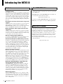 8
8
-
 9
9
-
 10
10
-
 11
11
-
 12
12
-
 13
13
-
 14
14
-
 15
15
-
 16
16
-
 17
17
-
 18
18
-
 19
19
-
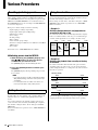 20
20
-
 21
21
-
 22
22
-
 23
23
-
 24
24
-
 25
25
-
 26
26
-
 27
27
-
 28
28
-
 29
29
-
 30
30
-
 31
31
-
 32
32
-
 33
33
-
 34
34
-
 35
35
-
 36
36


Yamaha MTX5 El manual del propietario
- Categoría
- Equipo musical
- Tipo
- El manual del propietario
- Este manual también es adecuado para
En otros idiomas
- français: Yamaha MTX5 Le manuel du propriétaire
- italiano: Yamaha MTX5 Manuale del proprietario
- English: Yamaha MTX5 Owner's manual
- Deutsch: Yamaha MTX5 Bedienungsanleitung
- русский: Yamaha MTX5 Инструкция по применению
- Nederlands: Yamaha MTX5 de handleiding
- português: Yamaha MTX5 Manual do proprietário
- dansk: Yamaha MTX5 Brugervejledning
- polski: Yamaha MTX5 Instrukcja obsługi
- čeština: Yamaha MTX5 Návod k obsluze
- svenska: Yamaha MTX5 Bruksanvisning
- Türkçe: Yamaha MTX5 El kitabı
- suomi: Yamaha MTX5 Omistajan opas
- română: Yamaha MTX5 Manualul proprietarului
Documentos relacionados
-
Yamaha EXo8 Manual de usuario
-
Yamaha V1 El manual del propietario
-
-
Yamaha QL5 El manual del propietario
-
Yamaha MA2030 El manual del propietario
-
-
Yamaha MTX3 El manual del propietario
-
-
Yamaha MRX7-D El manual del propietario
-
Otros documentos
-
Computer Gear 24-0846 Ficha de datos
-
LD Systems DIO 44 Manual de usuario
-
Tascam Line Output Dante Converter Euroblock Built-in DSP Mixer El manual del propietario
-
-
Alpine MRX-M50 Manual de usuario
-
Alpine MRX-M110 El manual del propietario
-
Panasonic CZANC2 Instrucciones de operación
-