Craftsman 316740930 El manual del propietario
- Categoría
- Podadoras de césped
- Tipo
- El manual del propietario
Este manual también es adecuado para

769-11999 / 00 10/16
Sears Brands Management Corporation, Hoffman Estates, IL 60179 U.S.A.
Visit our website: www.craftsman.com
CAUTION: Before using this product,
read this manual and follow all its Safety
Rules and Operating Instructions.
Operator’s Manual
• SAFETY
• ASSEMBLY
• OPERATION
• MAINTENANCE
• ESPAÑOL, P. 25
4-Cycle
Electric Start Capable
WEEDWACKER
®
GAS TRIMMERS
Model Nos. 316.74093* & 316.74097*
*The last digit of the model number varies.

All information, illustrations and specifications in this manual are based
on the latest product information available at the time of printing. We
reserve the right to make changes at any time without notice.
TABLE OF CONTENTS
Safety . . . . . . . . . . . . . . . . . . . . . . . . . . . . . . . . . . . . . . . . . . . . . . .2
Know Your Unit . . . . . . . . . . . . . . . . . . . . . . . . . . . . . . . . . . . . . . . .6
Specifications . . . . . . . . . . . . . . . . . . . . . . . . . . . . . . . . . . . . . . . . .7
Assembly . . . . . . . . . . . . . . . . . . . . . . . . . . . . . . . . . . . . . . . . . . . . .8
Oil and Fuel . . . . . . . . . . . . . . . . . . . . . . . . . . . . . . . . . . . . . . . . . .13
Starting and Stopping . . . . . . . . . . . . . . . . . . . . . . . . . . . . . . . . . .14
Operation . . . . . . . . . . . . . . . . . . . . . . . . . . . . . . . . . . . . . . . . . . .16
Maintenance . . . . . . . . . . . . . . . . . . . . . . . . . . . . . . . . . . . . . . . . .18
Cleaning and Storage . . . . . . . . . . . . . . . . . . . . . . . . . . . . . . . . . .23
Troubleshooting . . . . . . . . . . . . . . . . . . . . . . . . . . . . . . . . . . . . . .24
Warranty . . . . . . . . . . . . . . . . . . . . . . . . . . . . . . . . . . . . . . . . . . . . . .*
Repair Protectio
n Agre
ements . . . . . . . . . . . . . . . . . . . . . . . . . . . . .*
Service Numbers . . . . . . . . . . . . . . . . . . . . . . . . . . . . . . . . . . . . . . .*
2
© Sears Brands, LLC
SAFETY
SPARK ARRESTOR NOTE
NOTE: For users on U.S. Forest Land and in the states of
California, Maine, Oregon and Washington. All U.S. Forest Land
and the state of California (Public Resources Codes 4442 and
4443), Oregon and Washington require, by law that certain internal
combustion engines operated on forest brush and/or grass-covered
areas be equipped with a spark arrestor, maintained in effective
work
ing ord
er, or the engine be constructed, equipped and
maintained for the prevention of fire. Check with your state or local
authorities for regulations pertaining to these requirements. Failure
to follow these requirements could subject you to liability or a fine.
This unit is factory equipped with a spark arrestor. If it requires
replacement, contact a Sears Parts & Repair Service Center to
install the
appro
priate muffler assembly.
Read the operator’s manual and follow all warnings and safety
instructions. Failure to do so can result in serious injury to the
operator and/or bystanders.
CALIFORNIA PROPOSITION 65
WARNING:
This product contains a chemical
known to the state of California to cause cancer, birth defects
or other reproductive harm.
SYMBOL MEANING
WARNING:
Signals a SERIOUS hazard.
Failure to obey a safety WARNING symbol CAN result in
serious injury to yourself or to others.
CAUTION:
Signals a MODERATE hazard.
Failure to obey a safety CAUTION symbol MAY result in
property damage or injury to yourself or to others.
The purpose of safety symbols is to attract your attention to
possible dangers. The safety symbols, and their explanations,
deserve your careful attention and understanding. The safety
warnings do not by themselves eliminate any danger. The
instructions or warnings they give are not substitutes for proper
accident prevention measures.
NOTE: Advises you of information or instructions vital to the
operation
or maintenance of the equipment.
DANGER:
Signals an EXTREME hazard.
Failure to obey a safety DANGER symbol WILL result in
serious injury or death to yourself or to others.
NOTE: This operator's manual covers multiple models. Features
may vary by model. Not all features in this manual are applicable
to all models. The model depicted may differ from yours.
* For Warranty, Repair Protection Agreements, and Service
Number information, please refer to the separate Warranty /
Service Supplement.

3
• IMPORTANT SAFETY INSTRUCTIONS •
SAFETY WARNINGS FOR GAS UNITS
• Store fuel only in containers specifically designed and approved
for the storage of such materials.
• Always stop the engine and allow it to cool before filling the
tank. Never remove the fuel tank cap or add fuel when the
engine is hot. Always loosen the fuel tank cap slowly to relieve
any pressure in the tank before fueling.
• Always add fu
el in a clean, well-ventilated outdoor are
a where
there are no sparks or flames. DO NOT smoke.
• Never operate the unit without the fuel cap securely in place.
• Avoid creating a source of ignition for spilled fuel. Wipe up any
spilled fuel from the unit immediately, before starting the unit.
Move the unit at least 30 ft. (9.1 m) from the fueling source and
site before starting the engine. DO NOT smoke.
• N
ever start or run the unit inside a closed ro
om or building.
Breathing exhaust fumes can kill. Operate this unit only in a well-
ventilated outdoor area.
WARNING:
Gasoline is highly flammable and
its vapors can explode if ignited. Take the following
precautions:
WHILE OPERATING
• Wear safety glasses or goggles that meet current ANSI / ISEA
Z87.1 standards and are marked as such. Wear ear/hearing
protection when operating this unit. Wear a face mask or dust
mask if the operation is dusty.
• Wear heavy long pants, boots, gloves and a long sleeve shirt. Do
not wear loose clothing, jewelry, short pants, sandals or go
barefoot. Secure hair above shoulder level.
• The cut
ting head shield must always be in place while operating
t
he unit. Do not operate the unit without both trimming lines
extended and the proper line installed. Do not extend the
trimming line beyond the length of the shield.
• The cutting head should remain stationary when the engine
idles. If it does not, refer to Adjusting the Idle Speed.
• Adjust the handle to provide the best grip, if applicable.
• Make
sure
the cutting head is not in contact with anything
before starting the unit.
• Use the unit only in daylight or good artificial light.
• Avoid accidental starting. Be in the starting position whenever
pulling the starter rope. The operator and unit must be in a
stable position while starting. Refer to Starting and Stopping.
• Use the right tool. Only use this tool for its intended purpose.
Only use the u
nit as described in this manual.
• A
lways hold the unit with both hands when operating. Keep a
firm grip on both handles or grips.
• Do not overreach. Always keep proper footing and balance. Take
extra care when working on stairs, steep slopes or inclines. To
avoid serious injury, do not operate the unit while on a ladder or
a roof.
• Keep hands, face, and feet away from all moving parts. Do not
touch or try
to stop moving parts.
• Do not touch the engine, gear housing or muffler. These parts get
extremely hot from operation, even after the unit is turned off.
• D
o not operate the unit faster than the speed needed to do the
job. Do not run the unit at high speed when not in use.
• Do not force the unit. It will do a better, safer job when used at
the intended rate.
READ ALL INSTRUCTIONS BEFORE OPERATING
• Read the instructions carefully. Be familiar with the controls and
proper use of the unit. Know how to stop the unit and disengage
the controls quickly.
• Stay alert. Do not operate this unit when tired, ill or under the
influence of alcohol, drugs or medication.
• Never allow children to operate the unit. Teens must be trained,
accompanied and supervised by an adult. Never allow adults to
operate the unit witho
ut pro
per instruction.
• All guards and safety attachments must be installed properly
before operating the unit.
• Inspect the unit before use. Check for damaged parts. Check for
fuel leaks. Make sure all parts operate properly. Make sure all
fasteners are in place and secure. Make sure all moving parts are
properly aligned and are not bound. Replace parts that are cracked,
chipped, or damaged in any way.
Have all damaged or improperly
w
orking parts repaired or replaced by an authorized service
center. Do not operate the unit with loose or damaged parts.
• Only use the trimming line described in the Specifications section
of this manual. Never use metal-reinforced line, wire, chain or
rope. These can break off and become dangerous projectiles.
• Do not replace the cutting head with rigid or metal blades.
Doing
s
o could result in serious injury.
• Be aware of risk of injury to the head, hands and feet.
• Carefully inspect the area before starting the unit. Remove
rocks, broken glass, nails, wire, string and other objects that
may be thrown or become entangled with the unit.
• Clear the area of children, bystanders and pets; keep them
outside a 50-foot (15 m) radius, at a minimum. Even then, they are
still at
risk fro
m thrown objects. Encourage bystanders to wear
eye protection. If you are approached, stop the unit immediately.
• Squeeze the throttle control and check that it returns
automatically to the idle position. Make all adjustments or
repairs before using the unit.
• Do not change the engine governor settings or overspeed the
engine.
• This unit is intended for occasional, household use only.
WARNING:
When using the unit, all safety
instructions must be followed. Please read these
instructions before operating the unit in order to ensure the
safety of the operator and any bystanders. Please keep
these instructions for later use.

4
OTHER SAFETY WARNINGS
• Maintain the unit with care. Follow all maintenance instructions
in this manual.
• Do not perform maintenance procedures other than those
described in this manual. All service, other than the maintenance
procedures described in this manual, should be performed by a
Sears or other qualified service dealer.
• Never remove, modify or make inoperative any safety device
furnished with the
unit.
• B
efore inspecting, maintaining, cleaning, storing, transporting or
replacing any parts on the unit:
1. Stop the unit. Refer to Starting and Stopping.
2. Make sure all moving parts have stopped.
3. Allow the unit to cool.
4. Disconnect the spark plug wire.
• Secure the unit while transporting.
• Never store the unit with fuel in the tank, inside a building where
fumes may reach an open flame (pilot light
s, etc.) or sparks
(
switches, electrical motors, etc.).
• Store the unit in a dry place, secured or at a height to prevent
unauthorized use or damage. Keep the unit out of the reach of
children.
• Never douse or squirt the unit with water or any other liquid.
Keep handles dry and clean (free from debris, oil and grease).
Clean the unit after each use. Refer to Cleaning and Storage. Do
not use solvents or st
ro
ng detergents.
• Keep these instructions. Refer to them often and use them to
instruct other users. If you loan this unit to others, also loan
them these instructions.
SAVE THESE INSTRUCTIONS
• Always turn the unit off when operation is delayed or when
carrying the unit from one location to another. Make sure all
moving parts come to a complete stop.
• Before setting the unit down, always make sure the engine is off
a
nd all moving parts have stopped.
• If the unit strikes or becomes entangled with a foreign object,
stop the unit immediately. Check for damage. If damaged, do
not restart or operate the unit until it is repaired. Do not operate
the unit with loose or damaged parts.
• Turn the engine off and disconnect the spark plug for
maintenance or repair.
• Use only original equipment manufacturer (OEM) repl
acement
p
arts and accessories for this unit. Use of any other parts or
accessories could lead to serious injury to the user, or damage
to the unit, and void the warranty.
• Keep the unit clean. Carefully remove vegetation and other
debris that could block moving parts.
• To reduce fire hazard, replace a faulty muffler and spark arrestor.
Keep the engine and muffler free from grass, leaves, excessive
grease
or carbon build up.
• I
f the unit starts to vibrate abnormally, stop the unit immediately.
Inspect the unit for the cause of the vibration. Vibration is
generally an indicator of trouble.

5
• SAFETY & INTERNATIONAL SYMBOLS •
This operator's manual describes safety and international symbols and pictographs that may appear on this product. Read the operator's
manual for complete safety, assembly, operating and maintenance and repair information.
SYMBOL MEANING SYMBOL MEANING
• SAFETY ALERT SYMBOL
Indicates danger, warning or caution. May be used in
conjunction with other symbols or pictographs.
• READ OPERATOR'S MANUAL
WARNING:
Read the operator’s
manual(s) and follow all warnings and safety
instructions. Failure to do so can result in serious
injury to the operator and/or bystanders.
• WEAR EYE AND HEARING PROTECTION
WARNING:Thrown objects and loud
noise can cause severe eye injury and hearing loss.
Wear eye protection meeting current ANSI / ISEA
Z87.1 standards and ear protection when operating
this unit. Use a full face shield when needed.
• WEAR FOOT PROTECTION
Always wear heavy-duty, non-slip footwear when
operating this unit.
• WEAR HAND PROTECTION
Always wear heavy-duty, non-slip gloves when
handling this unit.
• HANDLE POSITION
Make sure the handle is positioned beyond the end of
the safety label.
• UNLEADED FUEL
Always use clean, fresh unleaded fuel.
• OIL
Refer to operator’s manual for the proper type of oil.
• DO NOT USE E85 FUEL IN THIS UNIT
WARNING:
It has been proven that fuel
containing greater than 10% ethanol will likely
damage this engine and void the warranty.
• ON/OFF STOP CONTROL
ON / START / RUN
• ON/OFF STOP CONTROL
OFF or STOP
• PRIMER BULB
Push primer bulb, fully and slowly, 10 times.
• THROWN OBJECTS CAN CAUSE SEVERE INJURY
WARNING:
Small objects can be
propelled at high speed, causing injury.
Min. 50 ft
15 m
• KEEP BYSTANDERS AWAY
WARNING:
Keep all bystanders,
especially children and pets, at least 50 feet (15 m)
from the operating area.
• HOT SURFACE
WARNING:Do not touch a hot muffler
or cylinder. You may get burned. These parts get
extremely hot from operation. When turned off, they
remain hot for a short time.
• SHARP BLADE
WARNING:There is a sharp blade on
the cutting head shield. To prevent serious injury, do
not touch the line cutting blade.
• DO NOT USE METAL BLADES
WARNING:To prevent serious injury, do
not replace the cutting head with rigid or metal blades.

Cutting Head
Shield
Fuel Cap
Handle
Cutting Head
Shaft Grip
Starter
Rope Grip
Throttle
Control
Spark PlugMuffler
On/Off Switch
Primer Bulb
Line Cutting Blade
Air Filter
Cover
Coupler
Shoulder Strap
/ Harness Loop
Throttle
Lockout
Oil Fill Plug
Speed Start™ Port
Upper Shaft
Housing
Lower Shaft
Housing
Hanger Cap
6
KNOW YOUR UNIT
Model No. 316.74093*
ASSEMBLY TOOLS REQUIRED
• Flat-head or T-20 Torx® Screwdriver
APPLICATIONS
As a trimmer:
• Cutting grass and light weeds
• Edging
• Decorative trimming around trees, fences, etc.
Other optional attachments may be used with this unit.

Cutting Head
Shield
Cutting Head
Line Cutting Blade
Handle
Shaft Grip
Throttle
Control
Spark Plug
Muffler
On/Off Switch
Coupler
Shoulder Strap
/ Harness Loop
Throttle
Lockout
Air Filter
Cover
Starter
Rope Grip
Fuel Cap
Primer Bulb
Oil Fill Plug
Speed Start™ Port
Upper Shaft
Housing
Lower Shaft
Housing
Hanger Cap
7
Model No. 316.74097*
SPECIFICATIONS
All specifications are based on the latest product information available at the time of printing. We reserve the right to make changes at any
time without notice.
Engine Type . . . . . . . . . . . . . . . . . . . . . . . . . . . . . . . . . . . . . . . . . . . . . . . . . . . . . . . . . . . . . . . . . . . . . . . . . . . . . . . . . . . . . . . Air-Cooled, 4-Cycle
Displacement (Model No. 316.74093*) . . . . . . . . . . . . . . . . . . . . . . . . . . . . . . . . . . . . . . . . . . . . . . . . . . . . . . . . . . . . . . . . . . . 32 cc (1.95 cu. in.)
Displacement (Model No. 316.74097*) . . . . . . . . . . . . . . . . . . . . . . . . . . . . . . . . . . . . . . . . . . . . . . . . . . . . . . . . . . . . . . . . . . . 30 cc (1.83 cu. in.)
Spark Plug Gap. . . . . . . . . . . . . . . . . . . . . . . . . . . . . . . . . . . . . . . . . . . . . . . . . . . . . . . . . . . . . . . . . . . . . . . . . . . . . . . . . . . . 0.025 in. (0.635 mm)
Spark Plug . . . . . . . . . . . . . . . . . . . . . . . . . . . . . . . . . . . . . . . . . . . . . . . . . . . . . . . . . . . . . . . . . . . . . . . . . Champion® RDZ4H or equivalent plug
Lubrication . . . . . . . . . . . . . . . . . . . . . . . . . . . . . . . . . . . . . . . . . . . . . . . . . . . . . . . . . . . . . . . .
. . . . . . . . . . . . . . . . . . . . . . . . . . . . . . . SAE 30 Oil
Crankcase Oil Capacity . . . . . . . . . . . . . . . . . . . . . . . . . . . . . . . . . . . . . . . . . . . . . . . . . . . . . . . . . . . . . . . . . . . . . . . . . . . . . . . . . 2.37 oz. (70 ml)
Fuel Tank Capacity . . . . . . . . . . . . . . . . . . . . . . . . . . . . . . . . . . . . . . . . . . . . . . . . . . . . . . . . . . . . . . . . . . . . . . . . . . . . . . . . . . . . . . 12 oz. (355 ml)
Approximate Unit Weight (No fuel) . . . . . . . . . . . . . . . . . . . . . . . . . . . . . . . . . . . . . . . . . . . . . . . . . . . . . . . . . . . . . . . 13.5 - 14.5 lbs. (6.1 - 6.6 kg)
Trimmer Mechanism. . . . . . . . . . . . . . . . . . . . . . . . . . . . . . . . . . . . . . . . . . . . . . . . . . . . . . . . . . . . . . . . . Bump Head or Fixed-Line Cutting Head
Trimming Line (Fixed-Line Cutting Head). . . . . . . . . . . . . . . . . . . . . . . . . . . . . . . . . . . . . . . . . . . . . . . . . . Hassle Free™ XTRA QUIET Spiral Line
Trimming Line Diameter (Bump Head) . . . . . . . . . . . . . . . . . . . . . . . . . . . . . . . . . . . . . . . . . . . . . . . . . . . . . . . . . . . . . . . . . . . 0.095 in. (2.41 mm)
Trimming Line Diameter (Fixed-Line Cutting Head) . . . . . . . . . . . . . . . . . . . . . . . . . . . 0.110 in.
(2.79 mm) Medium or 0.130 in. (3.30 mm) Larg
e
Cutting Path Diameter. . . . . . . . . . . . . . . . . . . . . . . . . . . . . . . . . . . . . . . . . . . . . . . . . . . . . . . . . . . . . . . . . . . . . . . . . . . . . . . . . . . 18 in. (45.7 cm)
ASSEMBLY TOOLS REQUIRED
• Flat-head Screwdriver
APPLICATIONS
As a trimmer:
• Cutting grass and light weeds
• Edging
• Decorative trimming around trees, fences, etc.
Other optional attachments may be used with this unit.

8
ASSEMBLY
INSTALLING THE CUTTING HEAD SHIELD
1. Remove the wing nut and washer from the cutting head shield.
2. Insert the short tab (the one without a hole) on the mount
bracket into the slot on the cutting head shield (Fig. 1).
3. Rotate the cutting head shield until the bolt on the cutting head
shield protrudes through the hole on the mount bracket (Fig. 1).
4. Place the washer onto the bolt (Fig. 2).
5. Scr
ew the wing nut onto the bolt until the cutting head shield is
f
irmly in place (Fig. 2).
WARNING:
To prevent serious personal injury, never
operate the unit without the cutting head shield in place.
Fig. 1
Mount Bracket
Cutting Head
Shield
Fig. 2
Washer
Bolt
Slot
Wing Nut
Tab
Bolt
Hole
Fig. 3
Upper Shaft
Housing
Fig. 4
Rear
Handle
Bracket
Upper Shaft
Housing
Tab
Slot
Ball Half
Ball Half
Ball
Shaft Grip
Safety
Label
INSTALLING AND ADJUSTING THE HANDLE
MODEL NO. 316.74093*
Installing the Handle
1. Place a ball half on each side of the upper shaft housing (Fig. 3).
Align each tab with its corresponding slot on the opposite ball
half (Fig. 3). Hold the two halves together. Make sure the ball is
positioned beyond the end of the safety label (Fig. 3).
2. Carefully push the rear handle bracket onto the upper shaft
housing (F
ig. 4). Make sure
the rear handle bracket is between
the ball and the shaft grip (Fig. 4).
3. Push the rear handle bracket onto the back of the ball and hold
it in place (Fig. 5).
4. Carefully maneuver the front handle bracket over the coupler
and push it onto the front of the ball (Fig. 5). Hold the front and
rear handle brackets together.
5. Insert a nut into one of the hexagonal recesses in the back of
th
e re
ar handle bracket (Fig. 6). Make sure the round side of the
nut faces outward. Hold the nut in place with a finger. Insert a
bolt into the corresponding hole in the front handle bracket (Fig.
6). Tighten the bolt with a flat-head or T20 Torx® screwdriver.
Repeat this step until all four (4) bolts are securely installed.
6. Push the latch pin completely into the small hook on the handle
(Fig. 7). Lift
the latch lever up and push it toward
the large hook
(Fig. 7). Push the latch loop over the large hook (Fig. 7).
7. Hold the unit in the operating position (Fig. 21). Move the handle
up or down the upper shaft housing to a comfortable location
(Fig. 8). Make sure the handle is positioned beyond the end of
the safety label (Fig. 8).

9
Fig. 5
Ball
Rear
Handle
Bracket
Front
Handle
Bracket
Coupler
Fig. 6
Fig. 8
Bolt (x4)
Nut (x4)
Handle
Safety Label
Upper Shaft
Housing
Latch Lever
Fig. 7
Small
Hook
Latch Loop
Large
Hook
Latch Pin
Latch
Lever
8. Tilt the handle to the desired position.
9. Flip the latch lever down to secure the handle.
Adjusting the Handle
If the handle requires adjustment:
1. Flip the latch lever up to loosen the handle (Fig. 8).
2. Hold the unit in the operating position (Fig. 21). Move the handle
up or down the upper shaft housing to a comfortable location
(Fig. 8). Make sure the handle is positioned beyond the end of
the safe
ty label (Fig. 8).
3
. Tilt the handle to the desired position.
4. Flip the latch lever down to secure the handle.

10
INSTALLING AND ADJUSTING THE HANDLE
MODEL NO. 316.74097*
Installing the Handle
1. Push the handle down onto the upper shaft housing (Fig. 9).
Make sure the bolt hole faces to the right (Fig. 9).
2. Insert the bolt into the bolt hole and push it through (Fig. 9).
Tighten the bolt with a flat-head screwdriver, but do not tighten
the bolt completely .
3. Hold the unit in the operating position (Fig. 21). Mov
e the handle
u
p or down the upper shaft housing to a comfortable location
(Fig. 9). Make sure the handle is positioned beyond the end of
the safety label (Fig. 9).
4. Tighten the bolt with a flat-head screwdriver until the handle is
secure.
Adjusting the Handle
If the handle requires adjustment:
1. Loosen the bolt with a flat-head screwdriver (Fig. 9).
2. Hold the unit in the operating position (Fig. 21). Mov
e the handle
up or down the upper shaft housing to a comfortable location
(Fig. 9). Make sure the handle is positioned beyond the end of
the safety label (Fig. 9).
3. Tighten the bolt with a flat-head screwdriver until the handle is
secure.
Fig. 9
Bolt Hole
Handle
Upper Shaft
Housing
Bolt
Safety Label

11
INSTALLING AND REMOVING THE ATTACHMENT
The coupler enables the use of various optional attachments.
Installing the Attachment
1. Remove the hanger cap from the attachment. Keep the hanger
cap for use when storing the attachment. If present, remove the
gray spacer from the coupler.
2. Set the unit on a flat, level surface.
3. Turn the knob counterclockwise to loosen the coupler (Fig. 10).
4. Align the releas
e button with the guide re
cess (Fig. 12).
5. Push the attachment straight into the coupler (Fig. 11) until the
release button snaps firmly into the primary hole (Fig. 12).
6. Turn the knob clockwise to tighten the coupler (Fig. 10).
Removing the Attachment
1. Set the unit on a flat, level surface.
2. Turn the knob counterclockwise to loosen the coupler (Fig. 10).
3. Press and hold the release button (Fig. 12)
.
4
. Pull the attachment straight out of the coupler (Fig. 11).
WARNING:
Before operating the unit, make sure the
release button is fully snapped into the primary hole and the
knob is securely tightened.
WARNING:
Unless specified otherwise, the release
button should be snapped into the primary hole only. Using
the wrong hole could lead to personal injury or damage to
the unit.
WARNING:
Before using any attachment, read and
understand the manual that came with the attachment.
Follow all safety information contained within.
WARNING:
To avoid serious personal injury and
damage to the unit, shut the unit off before removing or
installing an attachment.
Fig. 10
Knob
Tighten
Loosen
Fig. 12
Fig. 11
Coupler
Attachment
Release Button
Guide Recess
Primary Hole

12
Fig. 13
Strap
Buckle
Clip
Fig. 14
Clip
Fig. 15
Strap
Buckle
Center
Slot
Lower Slot
INSTALLING THE SHOULDER STRAP (OPTIONAL)
1. Push the strap up through the center slot in the buckle (Fig. 13).
2. Bend the strap over and push it down through the lower slot in
the buckle (Fig. 13).
3. Put the shoulder strap over the operator’s head and onto the left
shoulder.
4. Start the unit. Refer to Starting and Stopping.
5. Snap the clip onto the shoulder strap / harness loop (Fig. 14).
6. Adjust the sho
ulder strap to fit the operator (Fig. 15). Pull the
b
uckle up to loosen the shoulder strap. Pull the strap down to
tighten the shoulder strap.
Shoulder Strap
/ Harness Loop

13
OIL AND FUEL
USING THE RIGHT OIL
Use a high-quality SAE 30 weight oil. DO NOT use dirty oil. Failure
to use clean oil of the correct type can cause premature engine
wear and failure.
Fig. 16
Oil Fill Plug
Oil Fill Hole
O-Ring
ADDING OIL: INITIAL USE
NOTE: This unit was shipped without oil in the crankcase. Oil must
be added before starting the unit.
NOTE: This unit comes with a 2.37 fluid oz. (70 ml) container of oil.
1. Set the unit on a flat, level surface.
2. Unscrew the oil fill plug (Fig. 16).
3. Pour the entire container of oil into the oil fill hole (Fig. 16). DO
NOT overfill. Refer to Checking the Oil Level.
NOTE: Never add
oil to the fuel tank. This unit has a four-
cycle
engine. DO NOT mix oil with gasoline.
4. Wipe up any oil that may have spilled.
5. Make sure the O-ring is in place on the oil fill plug (Fig. 16).
6. Reinstall the oil fill plug.
WARNING:
OVERFILLING THE CRANKCASE MAY
CAUSE SERIOUS PERSONAL INJURY. Check the oil level
before each use. The importance of maintaining the proper
oil level cannot be overemphasized. Change the oil
according to the Maintenance Schedule.
USING THE RIGHT FUEL
The use of old fuel is the most common cause of performance
problems. Use only fresh, clean unleaded gasoline.
NOTE: This unit has a four-cycle engine. DO NOT mix oil with gasoline.
Definition of Blended Fuels
Today's fuels are often a blend of gasoline and oxygenates such as
ethanol, methanol or MTBE (ether). Alcohol-blended fuel absorbs
water. As little as 1% water in the fuel can ma
ke fuel and oil
s
eparate, forming acids when stored. ALWAYS use fresh fuel (less
than 30 days old).
NOTE: Dispose of old fuel according to federal, state and local
regulations.
Using Blended Fuels
If using a blended fuel:
• Always use fresh unleaded gasoline
• Use the fuel additive STA-BIL
®
or an equivalent
Using Fuel Additives
Use a fuel additive, such as STA-BIL Fuel Stabilizer or an
equivalent, to inhibit corro
sion and minimize gum deposits. Add 0.8
oz. (23 ml) of fuel additive per gallon of fuel, according to the
instructions on the container. NEVER add fuel additives directly to
the unit's fuel tank.
CAUTION:
DO NOT USE E85 FUEL IN THIS UNIT.
It has been proven that fuel containing greater than 10%
ethanol will likely damage this engine and void the warranty.
FUELING THE UNIT
1. Position the unit with the fuel cap facing up.
2. Slowly remove the fuel cap.
3. Place the fuel container spout into the fuel tank fill hole and fill
the tank.
NOTE: Do not overfill the tank.
4. Wipe up any fuel that may have spilled.
5. Reinstall the fuel cap.
6. Move the unit at least 30 ft. (9.1 m) from the fuel container and
the fueling site before starting the engine.
WARNING:
Gasoline is extremely flammable. Ignited
vapors may explode. Always stop the engine and allow it
to cool before filling the fuel tank. Do not smoke while
filling the tank. Keep sparks and open flames at a distance
from the area.
WARNING:
Remove the fuel cap slowly to avoid injury
from fuel spray. Never operate the unit without the fuel cap
securely in place.
WARNING:
Add fuel in a clean, well-ventilated outdoor
area. Wipe up any spilled fuel immediately. Avoid creating
a source of ignition for spilled fuel. Do not start the engine
until fuel vapors dissipate.

14
STARTING AND STOPPING
WARNING:
Operate this unit only in a well-ventilated
outdoor area. Carbon monoxide exhaust fumes can be
lethal in a confined area.
WARNING:
Avoid accidentally starting the unit. To avoid
serious injury, the operator and the unit must be in a stable
position when pulling the starter rope (Fig. 19).
STOPPING INSTRUCTIONS
1. Release the throttle control and allow the engine to idle.
2. Press and hold the On/Off switch in the Off (O) position until the
engine comes to a complete stop (Fig. 17).
STARTING INSTRUCTIONS
1. Check the oil level. Refer to Checking the Oil Level.
2. Fill the fuel tank. Refer to Fueling the Unit.
NOTE: There is no need to turn the unit on. The On/Off switch is in
the On ( I ) position at all times (Fig. 17).
3
. Slowly press and release the primer bulb 10 times (Fig. 18).
4. Crouch in the starting position (Fig. 19).
NOTE: PRESS and HOLD the throttle lockout, then SQUEEZE and
HOLD the throttle control for ALL further steps.
NOTE: To prevent the throttle control from being squeezed
accidentally, this unit has a throttle lockout. The throttle control
cannot be squeezed unless the throttle lockou
t is also engaged.
5
. Press and hold the throttle lockout. Squeeze and hold the
throttle control (Fig. 17). Pull the starter rope with a controlled
and steady motion 5 times to start the engine (Fig. 19).
NOTE: This unit uses the INCREDI-PULL™ starting system, which
significantly reduces the effort required to start the engine.
6. Install the shoulder strap (optional). Refer to Installing the
Shoulder Strap.
IF... the engine does not start, begin the starting procedure with step 3.
IF... the engine fails to start after 3 attempts: Press and hold the throttle
lockout. Squeeze and hold the throttle control. Pull the starter rope
with a controlled and steady motion until the unit starts.
IF... the engine stops while the throttle control is squeezed, begin
the starting procedure with step 3.
IF THE ENGINE IS HOT.
.. b
egin the starting procedure with step 3.
Fig. 17
Throttle Control
Throttle
Lockout
On/Off Switch
(I = On / O = Off)
Fig. 19
Starting
Position
Throttle Control
Starter Rope Grip
Fig. 18
Primer Bulb

15
STARTING INSTRUCTIONS
1. Check the oil level. Refer to Checking the Oil Level.
2. Fill the fuel tank. Refer to Fueling the Unit.
NOTE: There is no need to turn the unit on. The On/Off switch is in
the On ( I ) position at all times (Fig. 17).
3. Slowly press and release the primer bulb 10 times (Fig. 18).
4. Crouch in the starting position (Fig. 19).
5. Insert the Speed Start™ accessory into the Speed Start™
port
(
Fig. 20). Refer to the Operation section of the Speed Start™
accessory operator’s manual.
NOTE: PRESS and HOLD the throttle lockout, then SQUEEZE and
HOLD the throttle control for ALL further steps.
NOTE: To prevent the throttle control from being squeezed
accidentally, this unit has a throttle lockout. The throttle control
cannot be squeezed unless the throttle lockout is also engaged.
6. Press and hold th
e thro
ttle lockout. Squeeze and hold the
throttle control (Fig. 17). Run the Speed Start™ accessory in
intervals no longer than 2 seconds each until the unit starts.
7. Remove the Speed Start™ accessory from the unit.
8. Install the shoulder strap (optional). Refer to Installing the
Shoulder Strap.
IF... the engine does not start, begin the starting procedure with step 3.
IF... the engine fails to start afte
r 3 attempts: Pre
ss and hold the
throttle lockout. Squeeze and hold the throttle control. Run the
Speed Start™ accessory in intervals no longer than 2 seconds
each until the unit starts.
IF... the engine stops while the throttle control is squeezed, begin
the starting procedure with step 3.
IF THE ENGINE IS HOT... begin the starting procedure with step 3.
USING THE SPEED START™ ACCESSORY
This unit can be started with an optional Speed Start™ accessory
(items sold separately). Please refer to the Speed Start™ accessory
operator’s manual for the proper use of this feature.
Please contact your local Craftsman retailer, call 1-888-331-4569 or
visit www.craftsman.com for more information.
SPEED START ACCESSORIES
Item No. Description
316.85951 . . . . . . . . . . . . . . . . . . . . . . . . . . . . . .Plug-In Power Start
316.85952 . . . . . . . . . . . . . . . . . . . . . . . . . . . . . . . . . .
Power Bit Start
316.85953 . . . . . . . . . . . . . . . . . . . . . . . . . . . . .Cordless Power Start
STOPPING INSTRUCTIONS
1. Release the throttle control and allow the engine to idle.
2. Press and hold the On/Off switch in the Off (O) position until the
engine comes to a complete stop (Fig. 17).
Fig. 20
Speed Start™
Port

16
OPERATION
Fig. 21
HOLDING THE UNIT
• Stand in the operating position (Fig. 21). Stand up straight. Do
not bend over.
• Keep feet apart and firmly planted.
• Hold the shaft grip with the right hand. Keep the right arm
slightly bent.
• Hold the handle with the left hand. Keep the left arm straight.
• Hold the unit at waist level.
• Position the cutting head a few inches above the ground.
WARNING:
Always wear eye, hearing, hand, foot and
body protection to reduce the risk of injury when operating
this unit.
WARNING:
To prevent serious personal injury, avoid arm
contact with the engine while operating the unit. The
engine may be extremely hot.
TIPS FOR BEST RESULTS
• To direct clippings away from the operator, tilt the cutting head
slightly down to the right; cut from left to right whenever possible.
• Do not trim wet grass or weeds.
NOTE: Some line breakage will occur from:
• Entanglement with foreign matter
• Normal line fatigue
• Attempting to cut thick vegetation
• Forcing the line into objects such as walls or fence posts
ADJUSTING THE TRIMMING LINE LENGTH (BUMP HEAD)
The cutting head can be used as a bump head or as a fixed-line
head. When used as a bump head, trimming line can be released
from the cutting head without stopping the engine. Before doing so,
make sure the cutting head is loaded with line. Refer to Replacing
the Trimming Line (Bump Head) in the Maintenance section.
To release more line, lightly tap the bump knob on the ground (Fig.
22)
w
hile operating the unit at high speed. For best results, tap the
bump knob on bare ground or hard soil. Attempting to release line in
tall grass may stall the engine.
NOTE: Do not rest the cutting head on the ground while the unit is
running.
Each time the bump knob is tapped, about 1 inch (25.4 mm) of
trimming line is released.
NOTE: Always keep the trimming line fully extended. Line release
becomes
more difficult when the cutting line gets shorter.
A blade in the cutting head shield will cut the line to the proper
length if any excess line is released.
WARNING:
Do not remove or alter the line cutting blade
assembly. Excessive line length will make the unit
overheat. This may lead to serious personal injury or
damage to the unit.
Fig. 22
Bump Knob

17
EDGING
The trimmer attachment can be used for edging (Fig. 24).
Alternatively, a bladed lawn edger attachment can also be
purchased for use with this unit.
Rotating the Trimmer Attachment
When edging around sidewalks, flowerbeds, etc., rotate the trimmer
attachment 90° inside the coupler. DO NOT rotate the entire unit 90°.
1. Turn the knob counterclockwise to loosen the coupler (Fig. 25).
2. Press and hold the re
lease button (Fig. 25).
3. Rotate the attachment until the release button snaps firmly into
the 90° edging hole (Fig. 25).
4. Turn the knob clockwise to tighten the coupler (Fig. 25).
Maintaining the Trimming Line
Hard surfaces, such as sidewalks, can cause the trimming line to
wear down quickly or break.
• Bump Head: Frequently check and adjust the trimming line
length. Refer to Adjusting the Trimming
Line Length. Always
k
eep the trimming line fully extended.
• Fixed-Line Head: Frequently check the trimming line length.
Replace the trimming line as needed. Refer to Replacing the
Trimming Line.
• DO NOT force the unit. Make shallow cuts in as many passes as are
necessary to achieve the desired depth. Cut at a slow, even pace.
Fig. 24
WARNING:
Only snap the release button into the 90°
edging hole when edging with the trimmer attachment.
Using the 90° edging hole with other attachments could
lead to personal injury or damage to the unit.
WARNING:
To avoid serious personal injury and
damage to the unit, shut the unit off before rotating the
attachment.
Fig. 25
Release Button
90˚ Edging Hole
Knob
DECORATIVE TRIMMING
When trimming around trees, posts, fences, etc., rotate the whole
unit so that the cutting head is at a 30° angle to the ground (Fig. 23).
Fig. 23

18
MAINTENANCE
WARNING:
To avoid serious personal injury, always stop
the engine and allow it to cool before cleaning or maintaining
the unit. Never perform cleaning or maintenance while the
unit is running. Disconnect the spark plug wire to prevent
the unit from starting accidentally.
WARNING:
Wear protective clothing and observe all
safety instructions to prevent serious personal injury.
MAINTENANCE SCHEDULE
Perform these required maintenance procedures at the frequency
stated in the table. These procedures should also be a part of any
seasonal tune-up.
NOTE: Some maintenance procedures may require special tools or
skills. If you are unsure about these procedures, take the unit to
a Sears or other qualified service dealer. Call 1-888-331-4569
for more information.
NOTE: Maintenance, replace
ment, or re
pair of the emission control
devices and system may be performed by a Sears or other qualified
service dealer. Call 1-888-331-4569 for more information.
NOTE: Please read the California/EPA statement that came with the
unit for a complete listing of terms and coverage for the
emissions control devices, such as the spark arrestor, muffler,
carburetor, etc.
FREQUENCY MAINTENANCE REQUIRED
Every 10 hours • Clean and re-oil the air filter. Refer to
Maintaining the Air Filter.
After the first
10 hours and
at 38 hours
• Change the oil. Refer to Changing the Oil.
• Have the rocker arm clearance checked by
a Sears or other qualified service dealer.
• Check the spark plug condition and gap.
Refer to Maintaining the Spark Plug.
REPLACING THE TRIMMING LINE (BUMP HEAD)
Only use the trimming line described in the Specifications section.
Other types of trimming line may cause the unit to overheat or fail.
NOTE: Always use the correct line length when installing trimming
line. The line may not release properly if the line is too long.
NOTE: The cutting head will remain attached to the unit.
NOTE: DO NOT disassemble the cutting head to install new line.
Installing New Trimming Line (Bump Head)
1. If necessary, remove any old trimming line and/or obstructions
from the cutting head. Refer to Removing Old Trimming Line and
Obstructions (Bump Head).
2. Cut two 10-foot (3.0 m) lengths of new trimming line. Cut one
end of each line at a 30 degree angle (Fig. 27).
3. Turn the bump knob to align the mark on the bump knob with the
mark on the spoo
l cover (Fig. 26).
4
. Insert one of the lines into an eyelet on the cutting head (Fig. 27).
Use the angled end and push the line in about 3 inches (7.5 cm).
Repeat this process with the other line and remaining eyelet.
5. Turn the bump knob to wind the line until about 5 inches (12.5 cm)
protrude from each side of the cutting head (Fig. 28).
NOTE: DO NOT push the bump knob down while winding the line.
The
bump knob will only turn
one way, depending upon the unit
model.
NOTE: If too little line is left protruding, it could retract inside the
cutting head.
WARNING:
Never use metal-reinforced line, wire, chain or
rope. These can break off and become dangerous projectiles.
Fig. 26
Bump Knob
Marks
Spool Cover
30º
X
Fig. 27
Eyelet
Trimming Line

19
Removing Old Trimming Line and Obstructions (Bump Head)
1. When the trimming line runs out, the last piece should
automatically eject from the cutting head. If it does not, push the
bump knob down and pull the remaining line out of the cutting
head.
2. If the line will not come out or the cutting head is otherwise
obstructed:
a. Firmly press a tab on the cutting head with your thumb (Fig. 29).
DO NOT press
the tab with a scre
wdriver or other object.
b.Continue pressing the tab. Insert a flat-head screwdriver into
the gap between the outer spool and tab (Fig. 29).
c. Gently tilt the screwdriver to unlock the tab from the hole (Fig. 30).
d.Repeat the previous steps for the other tab.
e. Remove the spool cover (Fig. 30). DO NOT attempt to remove
any other parts of the cutting head.
f. Remove any old trimming line
and/or obstructions.
g
. Use a clean cloth to clean the inner reel, outer spool and spool
cover (Fig. 30).
h. Align the tabs on the spool cover with the holes on the outer
spool (Fig. 30). Push the spool cover onto the outer spool until
the tabs securely snap into the holes.
Fig. 28
Bump Knob
Fig. 29
Tab
Gap
Outer Spool
Fig. 30
Outer Spool
Inner Reel
Spool Cover
Tab
Hole
5 in. (12.5 cm)
5 in. (12.5 cm)
Flat-head
Screwdriver

20
REPLACING THE TRIMMING LINE
Only use the trimming line described in the Specifications section.
Other types of trimming line may cause the unit to overheat or fail.
NOTE: When using Craftsman® Hassle Free™ XTRA QUIET Spiral
Line, use the line best suited for the job at hand. Medium-sized (red)
line is designed for cutting grass and small weeds. Large-sized
(black) line is designed for cutting larger weeds and light brush.
1. Remove the old line from the cutting head. Push one end of the
trimming line into the cutting head until a loop of line protrudes
from the head. Pull the loop to remove the line (Fig. 33).
2. Use a clean cloth to clean the surface of the cutting head.
3. Insert the ends of the new trimming line into the holes in the
cutting head (Fig. 31). Push the line through the holes until both
e
nds pro
trude from the eyelets (Fig. 32).
4. Pull the ends of the line until the line is tight against the cutting
head. Make sure the ends of the line are of equal length (Fig. 33).
If one end is longer than the other, push the longer end back
through the cutting head partway and pull the shorter end out. If
necessary, repeat this process until both ends are of equal length.
5. Press the exposed loop of t
rimming line until it is tight against
t
he cutting head (Fig. 33).
WARNING:
Never use metal-reinforced line, wire, chain or
rope. These can break off and become dangerous projectiles.
Fig. 31
Fig. 32
Fig. 33
Trimming
Line
Eyelets
Trimming Line
Cutting Head
Loop
Holes
Cutting
Head
Trimming
Line

21
CHECKING THE OIL LEVEL
Inspecting the Oil Level Window
1. Stop the engine and allow it to cool.
2. Set the unit on a flat, level surface, such as a workbench or
table. The cutting head shield should hang over the edge so that
the engine is level (Fig. 34).
NOTE: Failure to keep the engine level may result in oil overfill.
3. Look into the oil level window; use a flashlight if necessary. The
oil level should
fill the window approximately halfway (Fig. 35).
I
f the oil level is too low, add oil. Refer to Adding Oil.
Adding Oil
1. Clean the area around the oil fill plug (Fig. 35) to prevent debris
from entering the oil fill hole.
2. Unscrew the oil fill plug.
3. Add oil to the oil fill hole until the oil level is approximately
halfway up the oil level window (Fig. 35).
• If the oil level is too high, tip the unit and drain the excess oil
i
nto an appropriate container.
4. Wipe up any oil that may have spilled.
5 Make sure the O-ring is in place on the oil fill plug (Fig. 35).
6. Reinstall the oil fill plug.
Fig. 34
WARNING:
Check the oil level before each use. The
importance of maintaining the proper oil level cannot be
overemphasized.
WARNING:
DO NOT overfill the crankcase.
OVERFILLING THE CRANKCASE MAY CAUSE SERIOUS
PERSONAL INJURY.
Fig. 35
Oil Fill Hole
Maximum
Oil Level
Oil Fill Plug
O-Ring
Oil Level
Window
Fig. 36
CHANGING THE OIL
Change the oil while the engine is still warm. The oil will flow freely
and carry away more impurities.
1. Clean the area around the oil fill plug (Fig. 35) to prevent debris
from entering the oil fill hole.
2. Unscrew the oil fill plug.
3. Tip the unit vertically to pour the oil out of the oil fill hole and into
a container (Fig. 36). Allow ample time for complete drainage.
NOTE: Disp
ose of the old oil accord
ing to federal, state and local
regulations.
4. Wipe up any oil that may have spilled.
5. Pour 2.37 fl.oz. (70 ml) of SAE 30 oil into the oil fill hole.
6. Wipe up any oil that may have spilled.
7. Make sure the O-ring is in place on the oil fill plug (Fig. 35).
8. Reinstall the oil fill plug.
WARNING:
DO NOT overfill the crankcase.
OVERFILLING THE CRANKCASE MAY CAUSE SERIOUS
PERSONAL INJURY. Refer to Checking the Oil Level.

22
MAINTAINING THE AIR FILTER
Failure to maintain the air filter can result in poor performance or
can cause permanent damage to the engine. Engine failure due to
improper air filter maintenance is not covered by the product warranty.
Cleaning the Air Filter
1. Unscrew the cover screw completely. Swing the air filter cover to
the right. Remove the air filter cover from the air filter housing
(Fig. 37).
2. Re
move the air filter fro
m the air filter housing (Fig. 37).
3. Wash the air filter in detergent and water. Rinse the air filter
thoroughly and allow it to dry.
4. Lightly coat the air filter with clean SAE 30 oil.
5. Squeeze the air filter to spread and remove excess oil.
6. Reinstall the air filter in the air filter housing (Fig. 37).
NOTE: Operating the unit without the air filter and air filter cover will
VOID the warranty.
7
. Insert the tab on the air filter cover into the hole on the air filter
housing. Swing the air filter cover to the left. Push the air filter
cover back onto the air filter housing. Insert the cover screw into
the air filter cover. Tighten the cover screw to secure the air filter
cover (Fig. 37).
NOTE: Do not over tighten as this may strip the screw.
Fig. 37
Air Filter
Air Filter
Cover
Air Filter
Housing
Cover
Screw
Tab
Hole
ADJUSTING THE IDLE SPEED
If the engine will not idle properly:
1. Start the engine. Refer to Starting and Stopping.
2. Release the throttle control and let the engine idle.
• If the engine stops, increase the idle speed. Use a small
Phillips screwdriver to turn the idle speed screw clockwise,
1/8 of a turn at a time, until the engine idles smoothly (Fig. 38).
• If the cutting head spins when the engine idles
, re
duce the idle
speed. Turn the idle speed screw counterclockwise, 1/8 of a
turn at a time, until the cutting head stops moving (Fig. 38).
WARNING:
The cutting head may spin during idle speed
adjustments. Wear protective clothing and observe all
safety instructions to prevent serious personal injury.
Fig. 38
Idle Speed Screw
MAINTAINING THE SPARK PLUG
1. Stop the engine and allow it to cool. Grasp the spark plug boot
firmly and pull it from the spark plug.
2. Clean around the spark plug. Remove the spark plug from the
cylinder head with a 5/8-inch socket, turning counterclockwise.
3. Inspect the spark plug. If the spark plug is cracked, fouled or
dirty, replace it with replacement part #753-05784, a Champion
RDZ4H or an equival
ent spark plug.
4. Use a feeler gauge to set the air gap at 0.025 in. (0.635 mm)
(Fig. 39).
5. Install the spark plug in the cylinder head. Tighten the spark plug
with a 5/8-inch socket, turning it clockwise until snug.
NOTE: If using a torque wrench, torque to:
110-120 in.•lb. (12.3-13.5 N•m). Do not over tighten.
6. Reattach the spark plug boot.
WARNING:
Do not sand blast, scrape or clean spark plug
electrodes. Grit in the engine could damage the cylinder.
Fig. 39
0.025 in.
(0.635 mm)

23
CLEANING AND STORAGE
CLEANING
Use a small brush to clean the outside of the unit. Do not use strong
detergents. Household cleaners that contain aromatic oils such as
pine and lemon, and solvents such as kerosene, can damage
plastic. Wipe off any moisture with a soft cloth.
WARNING:
To avoid serious personal injury, always stop
the engine and allow it to cool before cleaning or maintaining
the unit.
STORAGE
• Never store a fueled unit where fumes may reach an open flame
or spark.
• Allow the engine to cool before storing.
• Lock up the unit to prevent unauthorized use or damage.
• Store the unit in a dry, well-ventilated area.
• Store the unit out of the reach of children.
• To suspend the attachment from a hook, install the hanger cap
onto the attachment. Make sure the release button is securely
locked int
o one of the holes on the hanger cap.
S
hort-term Storage (1-2 weeks)
1. Store the unit in a horizontal position. If this is not possible, store
the unit vertically with the engine at the top.
Long-term Storage
1. Remove the fuel cap, tip the unit and drain the fuel into an
approved container. Reinstall the fuel cap.
2. Start the engine and allow it to run until it stalls. This ensures
that all fuel has been
drained fro
m the carburetor.
3. Allow the engine to cool. Remove the spark plug and put 5
drops of any high-quality motor oil into the cylinder. Pull the
starter rope slowly to distribute the oil. Reinstall the spark plug.
4. Thoroughly clean the unit and inspect it for any loose or
damaged parts. Repair or replace damaged parts and tighten
loose screws, nuts or bolts.
Preparing the Unit for Use after Long
-term Storage
1
. Remove the spark plug. Tip the unit and drain all of the oil from
the cylinder into an approved container. Reinstall the spark plug.
2. Change the oil. Refer to Changing the Oil.
NOTE: Do not use fuel that has been stored for more than 30 days.
Dispose of old fuel and oil according to federal, state and local
regulations.

24
The fuel tank is empty Fill the fuel tank with fresh fuel
The primer bulb was not pressed enough Press the primer bulb 10 times
The fuel is old (over 30 days) Drain the fuel tank and add fresh fuel
The spark plug is fouled Replace the spark plug
TROUBLESHOOTING
The fuel is old (over 30 days) Drain the fuel tank and add fresh fuel
The cutting head is bound with grass Stop the engine and clean the cutting head
The air filter is dirty Clean or replace the air filter
PROBLEM SOLUTION
The air filter is dirty Clean or replace the air filter
The fuel is old (over 30 days) Drain the fuel tank and add fresh fuel
The idle speed is incorrect Adjust the idle speed
The fuel is old (over 30 days) Drain the fuel tank and add fresh fuel
The air filter is dirty Clean or replace the air filter
The spark plug is fouled Replace the spark plug
If further assistance is required, take the unit to a Sears or other qualified service dealer.
The cutting head is bound with grass Stop the engine and clean the cutting head
The cutting head is out of line Refill the cutting head with new line
The inner reel is bound up Rewind the line
The cutting head is dirty Clean the inner reel and outer spool
The line is welded Open the cutting head and remove the welded section
The line is twisted Rewind the line
Not enough line is extended
Stop the unit, push the bump knob and pull the line until 4 inches
(102 mm) is outside of the cutting head
There is oil, cleaner or lubricant in the cutting head Clean and thoroughly dry the cutting head
THE ENGINE WILL NOT START
THE ENGINE WILL NOT IDLE
THE ENGINE WILL NOT ACCELERATE
THE ENGINE LACKS POWER OR STALLS
THE CUTTING HEAD WILL NOT ADVANCE LINE (BUMP HEAD)
THE CUTTING LINE ADVANCES UNCONTROLLABLY (BUMP HEAD)

Sears Brands Management Corporation, Hoffman Estates, IL 60179 U.S.A.
Visite nuestro sitio web: www.craftsman.com
PRECAUCIÓN: Antes de utilizar, este
producto lea este manual y siga todas
las reglas de seguridad e instrucciones
de operación.
Manual del Operador
• SEGURIDAD
• ENSAMBLAJE
• OPERACIÓN
• MANTENIMIENTO
Motor de 4 tiempos
Con Posibilidad de Arranque Eléctrico
RECORTADORAS A GASOLINA WEEDWACKER
®
Números de modelo 316.74093* & 316.74097*
*El último dígito del número de modelo varía.
769-11999 / 00 10/16

26
Toda la información, las ilustraciones y especificaciones que contiene
este manual se basan en la información más reciente del producto,
existente en el momento de la impresión. Nos reservamos el derecho
de hacer cambios en cualquier momento, sin previo aviso.
TABLA DE CONTENIDO
Seguridad . . . . . . . . . . . . . . . . . . . . . . . . . . . . . . . . . . . . . . . . . . .26
Conozca su unidad . . . . . . . . . . . . . . . . . . . . . . . . . . . . . . . . . . . .30
Especificaciones . . . . . . . . . . . . . . . . . . . . . . . . . . . . . . . . . . . . . .31
Ensamblaje . . . . . . . . . . . . . . . . . . . . . . . . . . . . . . . . . . . . . . . . . .32
Aceite y combustible . . . . . . . . . . . . . . . . . . . . . . . . . . . . . . . . . . .36
Arranque y parada . . . . . . . . . . . . . . . . . . . . . . . . . . . . . . . . . . . .37
Operación . . . . . . . . . . . . . . . . . . . . . . . . . . . . . . . . . . . . . . . . . . .39
Mant
enimiento . . . . . . . . . . . . . . . . . . . . . . . . . . . . . . . . . . . . . . .
41
Limpieza y almacenamiento . . . . . . . . . . . . . . . . . . . . . . . . . . . . .46
Localización y solución de problemas . . . . . . . . . . . . . . . . . . . . .47
Garantía . . . . . . . . . . . . . . . . . . . . . . . . . . . . . . . . . . . . . . . . . . . . . .*
Convenio de protección de reparación . . . . . . . . . . . . . . . . . . . . . .*
Números de servicio . . . . . . . . . . . . . . . . . . . . . . . . . . . . . . . . . . . .*
© Sears Brands, LLC
SEGURIDAD
NOTA SOBRE EL AMORTIGUADOR DE CHISPAS
NOTA: Para usuarios de los territorios de bosques de EE. UU. y
de los estados de California, Maine, Oregon y Washington.
Todos los territorios de bosques de EE. UU. y los estados de
California (Códigos de Recursos Públicos 4442 y 4443), Oregon y
Washington exigen por ley, que determinados motores de
combustión interna que se operan en zonas cubiertas por ma
lezas
d
e bosque y/o hierbas cuenten con un amortiguador de chispas
que se deberá mantener en condiciones de uso adecuadas o que el
motor se diseñe, equipe y mantenga para prevenir incendios.
Corrobore con las autoridades estatales o locales cuáles son las
normativas correspondientes a dichas exigencias. El
incumplimiento de dichos requerimientos podría generarle una
responsabilidad o una multa. La presen
te unidad se equipa en la
f
ábrica con un amortiguador de chispas. Si requiere reemplazo,
póngase en contacto con un Centro de Servicio de Reparaciones y
Piezas Sears para instalar el conjunto de silenciador adecuado.
Lea el manual del operador y siga todas las advertencias e
instrucciones de seguridad. Si no lo hace, el operador y/o los
observadores pueden sufrir lesiones graves.
PROPOSICIÓN 65 DEL ESTADO DE CALIFORNIA
ADVERTENCIA:
Este producto
contiene una sustancia química que según el Estado de
California puede producir cáncer, defectos de nacimiento
u otros problemas reproductivos.
SÍMBOLOS SIGNIFICADO
ADVERTENCIA:
Indica un peligro
GRAVE.
Si no se respeta un símbolo de ADVERTENCIA de
seguridad usted mismo u otras personas PUEDEN sufrir
lesiones graves.
PRECAUCIÓN:
Indica un peligro de
GRAVEDAD MODERADA.
Si no se respeta un símbolo de seguridad de
PRECAUCIÓN usted mismo u otras personas PUEDEN
sufrir lesiones o se PUEDEN producir daños materiales.
El objetivo de los símbolos de seguridad es dirigir su atención hacia
posibles peligros. Los símbolos de seguridad, así como sus
explicaciones, necesitan su atención y comprensión completas. Las
advertencias de seguridad no eliminan por sí mismas ningún
peligro. Las instrucciones o advertencias que contienen no
reemplazan a las medidas adecuadas de prevención de accidentes.
NOTA: Proporciona información
o instrucciones de vital importancia
p
ara el funcionamiento o el mantenimiento del equipo.
PELIGRO:
Indica un peligro EXTREMO.
Si no se respeta un símbolo de seguridad de PELIGRO
usted mismo u otras personas sufrirán lesiones graves o la
muerte.
NOTA: Este manual del operador cubre múltiples modelos. Las
características pueden variar según los modelos. No todas las
características de este manual son aplicables a todos los
modelos. El modelo descripto puede diferir del suyo.
* Para consultar Acuerdos de Protección para Reparaciones y
Garantía e Información sobre el Número de Servicio, por favor,
vea el Suplemento de Garantía / Servicio por separado.

27
• INSTRUCCIONES DE SEGURIDAD IMPORTANTES •
ADVERTENCIAS DE SEGURIDAD PARA LAS UNIDADES
A GASOLINA
• Almacene el combustible únicamente en recipientes diseñados
específicamente y aprobados para el almacenamiento de dichos
materiales.
• Detenga siempre el motor y déjelo enfriar antes de llenar el
depósito. Nunca retire la tapa del depósito de combustible ni
agregue combustible cuando el motor esté calient
e. Afloje siempre
lentamente la tapa del depósito de combustible para descargar la
presión que haya en el depósito antes de recargar combustible.
• A
gregue siempre combustible en una zona al aire libre, limpia y
bien ventilada, en la que no haya chispas ni llamas. NO fume.
• Nunca opere la unidad si la tapa del combustible no está bien
sujeta en su lugar.
• Evite que se genere una fuente de encendido para
el
c
ombustible derramado. Limpie de inmediato el combustible
derramado de la unidad, antes de encenderla. Mueva la unidad
al menos 30 pies (9.1m) de la fuente de combustible y del sitio
antes de arrancar el motor. NO fume.
• Nunca arranque ni use la unidad dentro de una habitación o de
una construcción cerrada. La inhalación de humos de escape
puede ser mortal. Opere esta unidad únicamente en una zona
bi
en ventilada, al aire
libre.
ADVERTENCIA:La gasolina es
sumamente inflamable y sus vapores pueden explotar si se
encienden. Adopte las siguientes precauciones:
DURANTE LA OPERACIÓN
• Utilice anteojos o antiparras de seguridad que cumplan con las
normas ANSI / ISEA Z87.1 vigentes y que tengan la
identificación correspondiente. Utilice una protección auditiva al
operar esta unidad. Utilice una máscara facial o para polvos si la
máquina levanta polvo durante su funcionamiento.
• Use pantalones largos y gruesos, botas, guantes y camisa de
mangas largas. No use ropa h
olgada, alhajas, pantalones
c
ortos, sandalias ni ande descalzo. Sujétese el cabello a nivel de
los hombros.
• El protector del cabezal de corte siempre debe estar colocado
mientras se opera la unidad. No utilice la unidad si no están
extendidos ambos hilos de recorte y si no está instalado el hilo
adecuado. No extienda el hilo de recorte más allá de la longitud
del protector.
• El cabezal de corte debe perm
anecer fijo cuando el motor
f
unciona al ralentí. Si no funciona, consulte Ajuste de la
velocidad de ralentí.
• Ajuste la manija para que brinde el mejor agarre, si corresponde.
• Compruebe que el cabezal de corte no esté en contacto con
nada antes de poner en marcha la unidad.
• Use la unidad solamente con luz de día o con una buena luz artificial.
• Evite arranques accidentales. Permanezca en la posición
de
a
rranque siempre que tire de la cuerda de arranque. El operador
y la unidad deben estar en una posición estable durante el
arranque. Consulte Arranque y Parada.
• Utilice la herramienta apropiada. Use esta herramienta sólo para
el propósito para el que fue diseñada. Sólo use la unidad como
se indica en este manual.
• Sostenga siempre la unidad con ambas manos durante la
operación. Sostenga firmemente a
mbas manijas o empuñaduras.
LEA TODAS LAS INSTRUCCIONES ANTES DE USAR LA
UNIDAD
• Lea las instrucciones con atención. Debe familiarizarse con los
controles y con el uso apropiado de la unidad. Sepa cómo
detener la unidad y desconectar los controles rápidamente.
• Manténgase alerta. No opere esta unidad si está cansado,
enfermo o bajo la influencia de alcohol, drogas o medicamentos.
• Nunca permita a los niñ
os operar la unidad. Los adolescentes
d
eben ser entrenados, acompañados y supervisados por un
adulto. Nunca permita a los adultos operar la unidad sin las
instrucciones adecuadas.
• Se deben instalar correctamente todos los protectores y
accesorios de seguridad antes de operar la unidad.
• Inspeccione la unidad antes de usarla. Verifique si hay piezas
dañadas. Compruebe si hay pérdidas de combustible.
Comp
ruebe que todas las piezas funcionen corre
ctamente.
Compruebe que todas las sujeciones estén en su lugar y bien
ajustadas. Compruebe que todas las piezas móviles queden
adecuadamente alineadas y no se atasquen. Reemplace las
piezas que estén agrietadas, astilladas o dañadas de cualquier
manera. Haga reparar o reemplazar por un centro de servicio
técnico autorizado todas las piezas que estén dañadas o qu
e no
f
uncionen adecuadamente. No utilice la unidad si hay piezas
sueltas o dañadas.
• Use únicamente el hilo de recorte que se describe en la sección
Especificaciones de este manual. Nunca use un hilo, un cable,
una cadena o una cuerda de metal reforzados. Podrían
separarse y convertirse en proyectiles peligrosos.
• No cambie el cabezal de corte por cuchillas rígidas o de metal.
Si lo hace, podría provocar
lesiones graves.
•
Tenga en cuenta el riesgo de lesiones en la cabeza, las manos y
los pies.
• Inspeccione el área con atención antes de arrancar la unidad.
Extraiga las rocas, los vidrios rotos, los clavos, los cables,
cordeles y demás objetos que podrían ser arrojados o enredarse
en la unidad.
• Despeje la zona de niños, observadores y mascotas;
manténgalos fuera de un radio de 50 pies (15 m), como mínim
o.
I
ncluso a esa distancia, sigue el riesgo de ser alcanzados por
los objetos arrojados por el aire. Sugiérales a los observadores
que usen protección ocular. Si alguien se le aproxima, detenga
la unidad de inmediato.
• Apriete el control del acelerador y verifique que vuelva
automáticamente a la posición de ralentí. Realice todos los
ajustes o las reparaciones antes de usar la unidad.
• No cambie la confi
guración del re
gulador del motor ni acelere
demasiado el motor.
• Esta unidad está diseñada para uso ocasional, para el hogar
únicamente.
ADVERTENCIA:
Se deben respetar
todas las instrucciones de seguridad al usar la unidad. Por
favor, lea estas instrucciones antes de utilizar la unidad para
garantizar la seguridad del operador y los observadores. Por
favor, guarde estas instrucciones para su uso posterior.

28
• No se extienda demasiado. Siempre debe estar bien afirmado y
mantener el equilibrio adecuado. Tenga cuidado al trabajar
sobre escalinatas, cuestas empinadas o pendientes. Para evitar
lesiones graves, no haga funcionar la unidad desde una escalera
de mano o un techo.
• Mantenga las manos, el rostro y los pies alejados de todas las
piezas móviles. No toque ni intente detener las piezas móviles.
• No toq
ue el motor,
el alojamiento del engranaje ni el silenciador.
Estas partes se ponen extremadamente calientes por el
funcionamiento, incluso después de que se apaga la unidad.
• No opere la unidad a una velocidad mayor a la necesaria para la
tarea. No haga funcionar la unidad a alta velocidad cuando no
está en uso.
• No exija demasiado a la unidad. Si se usa a la velocidad para la
que fue diseñada, realizará
un trabajo más eficiente y seguro
.
• Apague siempre la unidad cuando la operación se encuentre
demorada o cuando la unidad se traslade de un lugar a otro.
Compruebe que todas las piezas móviles se detengan
completamente.
• Antes de apoyar la unidad, siempre asegúrese de que el motor
esté apagado y que todas las piezas móviles se hayan detenido.
• Si la unidad golpea o se enreda con un objeto extraño, deten
ga
l
a unidad de inmediato. Controle si la unidad está dañada. Si
hay daño, no vuelva a arrancar o hacer funcionar la unidad
hasta hacerlo arreglar. No utilice la unidad si hay piezas sueltas
o dañadas.
• Apague el motor y desconecte la bujía para realizar tareas de
mantenimiento o reparación.
• Use sólo piezas de reemplazo y accesorios del fabricante del
equipo original (OEM) para esta unidad. Si usa cualq
uier otra
p
ieza o accesorio, el usuario podría lesionarse gravemente o la
unidad podría dañarse y se anularía la garantía.
• Mantenga limpia la unidad. Quite con cuidado cualquier resto de
vegetación u otros residuos que puedan bloquear las piezas móviles.
• A fin de reducir el riesgo de incendio, reemplace el silenciador y
el amortiguador de chispas si están averiados. Mantenga el
motor y el silenciador
libre
s de hierbas, hojas y de la
acumulación excesiva de grasa o de carbono.
• Si la unidad comienza a vibrar en forma anormal, deténgala de
inmediato. Inspeccione la unidad para determinar la causa de la
vibración. La vibración por lo general indica que hay algún
problema.
OTRAS ADVERTENCIAS DE SEGURIDAD
• El mantenimiento de la unidad debe ser minucioso. Siga todas
las instrucciones de mantenimiento de este manual.
• N
o realice ningún procedimiento de mantenimiento que no
figure en este manual. Todos los servicios, que no sean los
procedimientos de mantenimiento descritos en este manual,
deberán realizarse por un centro de Sears u otro centro de
servicio calificado.
• Nunca extraiga, modifique o deje inoperativo ningún dispositivo
de seguridad que venga con la unidad.
• Antes de inspeccionar, limpiar, guard
ar o transportar la unidad, o
d
e hacer tareas de reparación o mantenimiento o reemplazar
alguna de sus piezas:
1. Detenga la unidad. Consulte Arranque y Parada.
2. Asegúrese de que se hayan detenido todas las piezas móviles.
3. Deje que la unidad se enfríe.
4. Desconecte el cable de la bujía.
• Sujete la unidad durante el transporte.
• Nunca almacene la unidad con combustible en el depósito, en el
interior de u
na construcción donde las emanaciones puedan
a
lcanzar una llama abierta (luces piloto, etc.) o chispas
(interruptores, motores eléctricos, etc.).
• Almacene la unidad en un lugar seco, asegurada o a una altura
que evite que se la use sin autorización o se la dañe. Mantenga
la unidad lejos del alcance de los niños.
• Nunca rocíe ni arroje chorros de agua ni de ningún otro líquido a la
unidad. Mantenga las
manijas secas y limpias (sin residuos, aceite
ni grasa). Limpie la unidad luego de cada uso. Consulte Limpieza y
a
lmacenamiento. No utilice solventes o detergentes fuertes.
• Guarde estas instrucciones. Consúltelas con frecuencia y úselas
para capacitar a otros usuarios. Si le presta esta unidad a otras
personas, también debe prestarles estas instrucciones.
GUARDE ESTAS
INSTRUCCIONES

29
• SÍMBOLOS INTERNACIONALES Y DE SEGURIDAD •
Este manual del operador describe símbolos de seguridad e internacionales, así como pictogramas, que pueden aparecer en este producto.
Lea el manual del operador para obtener información completa sobre seguridad, montaje, funcionamiento, mantenimiento y reparaciones.
SÍMBOLOS SIGNIFICADO SÍMBOLOS SIGNIFICADO
• SÍMBOLO DE ALERTA DE SEGURIDAD
Indica peligro, advertencia o precaución. Puede
utilizarse junto con otros símbolos o pictogramas.
• LEA EL MANUAL DEL OPERADOR
ADVERTENCIA:
Lea el (los)
manual(es) del operador y cumpla todas las
advertencias e instrucciones de seguridad. Si no lo
hace, el operador y/o los observadores pueden sufrir
lesiones graves.
• UTILICE PROTECCIÓN OCULAR Y AUDITIVA
ADVERTENCIA:
Los objetos que
son arrojados por el aire y los ruidos fuertes pueden
provocar graves lesiones oculares y pérdidas de
audición. Cuando opere esta unidad, utilice
protección ocular que cumpla con las normas ANSI /
ISEA Z87.1 vigentes y protectores auditivos. Utilice
una máscara que cubra todo el rostro si es necesario.
• UTILICE PROTECCIÓN DE PIES
Siempre utilice calzado reforzado, antideslizante,
cuando haga funcionar esta unidad.
• UTILICE PROTECCIÓN DE MANOS
Siempre utilice guantes reforzados, antideslizantes,
cuando manipule esta unidad.
• POSICIÓN DE MANIJA
Compruebe que la manija esté ubicada más allá del
extremo de la etiqueta de seguridad.
• COMBUSTIBLE SIN PLOMO
Utilice siempre combustible limpio, nuevo y sin plomo.
• ACEITE
Consulte el manual del operador para conocer el tipo
adecuado de aceite.
• NO UTILICE COMBUSTIBLE E85 EN ESTA UNIDAD
ADVERTENCIA:Se ha
demostrado que el combustible que contiene más de
un 10% de etanol es probable que dañe este motor y
anule la garantía.
• APAGADO/ENCENDIDO DE CONTROL DE PARADA
ENCENDIDO / ARRANQUE / MARCHA
• APAGADO/ENCENDIDO DE CONTROL DE PARADA
APAGADO o PARADA
• BULBO DEL CEBADOR
Presione por completo el bulbo del cebador
lentamente 10 veces.
• LOS OBJETOS ARROJADOS PUEDEN PROVOCAR
LESIONES GRAVES
ADVERTENCIA:Es posible que se
arrojen objetos pequeños por el aire a alta velocidad,
lo cual puede provocar lesiones.
Min. 50 ft
15 m
• MANTENGA ALEJADOS A LOS OBSERVADORES
ADVERTENCIA:Mantenga a
todos los observadores, especialmente a los niños y
las mascotas, al menos a 50 pies (15 m) de la zona de
trabajo.
• SUPERFICIE CALIENTE
ADVERTENCIA:No toque el
silenciador o el cilindro cuando estén calientes. Puede
quemarse. Estas piezas se calientan extremadamente
durante el funcionamiento. Una vez apagadas,
continúan calientes durante un período breve.
• CUCHILLA AFILADA
ADVERTENCIA:Hay una cuchilla
afilada sobre el protector del cabezal de corte. A fin
de evitar lesiones graves, no toque la cuchilla de corte
del hilo.
• NO UTILICE CUCHILLAS DE METAL
ADVERTENCIA:
Para evitar
lesiones graves, no reemplace el cabezal de corte por
cuchillas rígidas o de metal.

Protector
del cabezal
de corte
Tapa de
combustible
Manija
Cabezal de corte
Empuñadura del eje
Empuñadura
cuerda de
arranque
Control del acelerador
Bujía de
encendido
Silenciador
Interruptor
encendido /
apagado
Bulbo del cebador
Cuchilla de corte de hilo
Tapa del
filtro de aire
Acoplador
Correa de hombro /
Presilla de enganche
del arnés
Tapón para
llenado de aceite
Bloqueo del
acelerador
Puerto
Speed Start™
Alojamiento del
eje superior
Alojamiento del eje inferior
Tapa de suspensión
Nº de modelo 316.74093*
30
CONOZCA SU UNIDAD
HERRAMIENTAS NECESARIAS PARA
EL ENSAMBLAJE
• Destornillador de cabeza plana o T-20 Torx®
APLICACIONES
Como recortadora:
• Corta hierbas y malezas ligeras
• Bordeado
• Recorte decorativo alrededor de árboles, vallas, etc.
Con esta unidad se pueden usar otros dispositivos de sujeción
opcionales.

Protector
del cabezal
de corte
Cabezal de corte
Cuchilla de corte de hilo
Manija
Empuñadura del eje
Control del acelerador
Bujía de encendido
Silenciador
Interruptor
encendido / apagado
Tapa del
filtro de aire
Acoplador
Correa de hombro /
Presilla de
enganche del arnés
Bloqueo del
acelerador
Empuñadura
cuerda de
arranque
Tapa de
combustible
Bulbo del cebador
Tapón para
llenado de aceite
Puerto
Speed Start™
Alojamiento del
eje superior
Alojamiento del
eje inferior
Tapa de suspensión
31
Nº de modelo 316.74097*
ESPECIFICACIONES
Todas las especificaciones están basadas se basan en la información más reciente sobre el producto disponible al momento de la
impresión. Nos reservamos el derecho a realizar cambios en cualquier momento sin previo aviso.
Tipo de motor . . . . . . . . . . . . . . . . . . . . . . . . . . . . . . . . . . . . . . . . . . . . . . . . . . . . . . . . . . . . . . . . . . . . . . . . . . . Refrigerado por aire, de 4 ciclos
Desplazamiento (N° de modelo 316.74093*) . . . . . . . . . . . . . . . . . . . . . . . . . . . . . . . . . . . . . . . . . . . . . . . . . . . . . 32 cc (1.95 pulgadas cúbicas)
Desplazamiento (N° de modelo 316.74097*) . . . . . . . . . . . . . . . . . . . . . . . . . . . . . . . . . . . . . . . . . . . . . . . . . . . . . 30 cc (1.83 pulgadas cúbicas)
S
eparación de las bujías . . . . . . . . . . . . . . . . . . . . . . . . . . . . . . . . . . . . . . . . . . . . . . . . . . . . . . . . . . . . . . . . . . . . . . . 0.025 pulgadas (0.635 mm)
Bujía de encendido. . . . . . . . . . . . . . . . . . . . . . . . . . . . . . . . . . . . . . . . . . . . . . . . . . . . . . . . . . . . . . . . . . Champion® RDZ4H o bujía equivalente
Lubricación . . . . . . . . . . . . . . . . . . . . . . . . . . . . . . . . . . . . . . . . . . . . . . . . . . . . . . . . . . . . . . . . . . . . . . . . . . . . . . . . . . . . . . . . . . . . Aceite SAE 30
Capacidad de aceite del cárter . . . . . . . . . . . . . . . . . . . . . . . . . . . . . . . . . . . . . . . . . . . . . . . . . . . . . . . . . . . . . . . . . . . . . . . . . 2.37 onzas (70 ml)
Capacidad del depósito de combustible . . . . . . . . . . . . . . . . . . . . . . . . . . . . . . . . . . . . . . . . . . . . . . . . . . . . . . . . . . . . . . . . . . 12 onzas (355 ml)
Peso aproximado de la unidad (sin combustible) . . . . . . . . . . . . . . . . . . . . . . . . . . . . . . . . . . . . . . . . . . . . . . . . . . 13.5 - 14.5 libras (6.1 - 6.6 kg)
Mecanismo de recorte . . . . . . . . . . . . . . . . . . . . . . . . . . . . . . . . . . . . . . . . . . . . . . . . . . . . . . Cabezal de impacto o cabezal de corte de h
ilo fijo
L
ínea de Corte (Cabezal de corte de hilo fijo) . . . . . . . . . . . . . . . . . . . . . . . . . . . . . . . . . . . . . . . . . . . . Línea Espiral Hassle Free™ XTRA QUIET
Diámetro del hilo de recorte (Cabezal de impacto) . . . . . . . . . . . . . . . . . . . . . . . . . . . . . . . . . . . . . . . . . . . . . . . . . . . . 0.095 pulgadas (2.41 mm)
Diámetro del hilo de recorte (Cabezal de corte de hilo fijo) . . . . . . . . 0.110 pulgadas (2.79 mm) Mediana o 0.130 pulgadas (3.30 mm) Grande
Diámetro de la senda de corte. . . . . . . . . . . . . . . . . . . . . . . . . . . . . . . . . . . . . . . . . . . . . . . . . . . . . . . . . . . . . . . . . . . . . . . 18 pulgadas (45.7 cm)
HERRAMIENTAS NECESARIAS PARA
EL ENSAMBLAJE
• Destornillador de cabeza plana
APLICACIONES
Como recortadora:
• Corta hierbas y malezas ligeras
• Bordeado
• Recorte decorativo alrededor de árboles, vallas, etc.
Con esta unidad se pueden usar otros dispositivos de sujeción
opcionales.

32
ENSAMBLAJE
INSTALACIÓN DEL PROTECTOR DEL CABEZAL DE CORTE
1. Extraiga la tuerca de mariposa y la arandela del protector del
cabezal de corte.
2. Inserte la lengüeta corta (la que no tiene orificio) en el soporte
de montaje dentro de la ranura del protector del cabezal de
corte (Fig. 1).
3. Rote el protector del cabezal de corte hasta que el perno en el
protector del cabezal de corte sobresalga a través del o
rificio
d
el soporte de montaje (Fig. 1).
4. Coloque una arandela sobre el perno (Fig. 2).
5. Atornille la tuerca mariposa sobre el perno hasta que el
protector del cabezal de corte esté firmemente colocado en su
lugar (Fig. 2).
ADVERTENCIA:
A fin de evitar que se produzcan
lesiones personales graves, no opere nunca la unidad sin
el protector del cabezal de corte en su lugar.
Fig. 1
Soporte de montaje
Protector
del cabezal
de corte
Fig. 2
Arandela
Perno
Ranura
Tuerca de
mariposa
Lengüeta
Perno
Orificio
Fig. 3
Alojamiento del
eje superior
Fig. 4
Soporte de
la manija
trasera
Alojamiento del
eje superior
Lengüeta
Ranura
Media bola
Media bola
Bola
Empuñadura
del eje
Etiqueta de
seguridad
INSTALACIÓN Y AJUSTE DE LA MANIJA
Nº DE MODELO 316.74093*
Instalación de la manija
1. Coloque media rótula a cada lado del alojamiento del eje
superior (Fig. 3). Alinee cada lengüeta con su correspondiente
ranura de la media bola opuesta (Fig. 3). Junte las dos medias
bolas. Compruebe que la bola esté ubicada más allá del
extremo de la etiqueta de seguridad (Fig. 3).
2. Con cuidado empuj
e la ménsula de la manija trasera sobre
el
alojamiento del eje superior (Fig. 4). Verifique que el soporte de la
manija trasera quede entre la bola y la empuñadura del eje (Fig. 4).
3. Deslice el soporte de la manija trasera hacia la parte posterior
de la bola y fíjelo (Fig. 5).
4. Maniobre cuidadosamente el soporte de la manija delantera
hacia el acoplador y deslícelo hacia la parte anterior de la bola
(F
ig. 5). Junte los soportes de la manija delantera y trasera.
5. Inserte una tuerca en una de las entrantes hexagonales de la
parte posterior del soporte de la manija trasera (Fig. 6). Verifique
que el lado redondo de la tuerca mira hacia afuera. Fije la tuerca
en su lugar con un dedo. Inserte un perno en el correspondiente
orificio del soporte de la manija delantera (Fig. 6). Ajuste el perno
con un desto
rnillador de cabeza plana o T20 Torx®. Repita este
paso hasta que los cuatro (4) pernos estén bien instalados.
6
. Empuje el pasador retén por completo en el gancho pequeño de
la manija (Fig. 7). Levante la palanca retén y empújela hacia el
gancho grande (Fig. 7). Deslice la traba retén sobre el gancho
grande (Fig. 7).

33
Fig. 5
Bola
Soporte de
la manija
trasera
Soporte de
la manija
anterior
Acoplador
Fig. 6
Fig. 8
Perno (x4)
Tuerca (x4)
Manija
Etiqueta de
seguridad
Alojamiento
del eje
superior
Palanca retén
Fig. 7
Gancho
pequeño
Traba retén
Gancho
grande
Pasador retén
Palanca
retén
7. Mantenga la unidad en la posición de funcionamiento (Fig. 21).
Mueva la manija hacia arriba o abajo del alojamiento del eje
superior hasta que esté en una posición cómoda (Fig. 8).
Compruebe que la manija esté ubicada más allá del extremo de
la etiqueta de seguridad (Fig. 8).
8. Incline la manija hasta la posición deseada.
9. Baje la palanca retén para sujetar la manija.
Ajuste de la manija
Si la manija r
equiere
ajustes:
1. Levante la palanca retén para aflojar la manija (Fig. 8).
2. Mantenga la unidad en la posición de funcionamiento (Fig. 21).
Mueva la manija hacia arriba o abajo del alojamiento del eje
superior hasta que esté en una posición cómoda (Fig. 8).
Compruebe que la manija esté ubicada más allá del extremo de
la etiqueta de seguridad (Fig. 8).
3. Incline la manija hasta la posición deseada.
4. Baj
e la palanca re
tén para sujetar la manija.

34
INSTALACIÓN Y AJUSTE DE LA MANIJA
Nº DE MODELO 316.74097*
Instalación de la manija
1. Oprima la manija hacia abajo sobre el alojamiento del eje
superior (Fig. 9). Asegúrese de que el orificio del perno mire
hacia la derecha (Fig. 9).
2. Inserte el perno en el orificio del perno y oprímalo para que pase
a través de él (Fig. 9). Ajuste el perno con un destornillador de
cabeza plana, pero no lo ajuste compl
etamente.
3
. Mantenga la unidad en la posición de funcionamiento (Fig. 21).
Mueva la manija hacia arriba o abajo del alojamiento del eje
superior hasta que esté en una posición cómoda (Fig. 9).
Compruebe que la manija esté ubicada más allá del extremo de
la etiqueta de seguridad (Fig. 9).
4. Ajuste el perno con un destornillador de cabeza plana hasta que
la manija quede segura.
Ajuste de la manija
Si la mani
ja requiere ajustes:
1. Afloje el perno con un destornillador de cabeza plana (Fig. 9).
2. Mantenga la unidad en la posición de funcionamiento (Fig. 21).
Mueva la manija hacia arriba o abajo del alojamiento del eje
superior hasta que esté en una posición cómoda (Fig. 9).
Compruebe que la manija esté ubicada más allá del extremo de
la etiqueta de seguridad (Fig. 9).
3. Ajuste el perno con un destornillador d
e cabeza plana hasta que
l
a manija quede segura.
Fig. 9
Orificio del perno
Manija
Alojamiento
del eje
superior
Perno
Etiqueta de
seguridad
INSTALACIÓN Y EXTRACCIÓN DEL ACCESORIO
El acoplador permite el uso de varios accesorios opcionales.
Instalación del accesorio
1. Quite la tapa de suspensión del accesorio. Guarde la tapa de
suspensión para utilizarla al almacenar el accesorio. De estar
presente, extraiga el espaciador gris del acoplador.
2. Coloque la unidad en una
superficie plana y nivelada.
3
. Gire la perilla en el sentido contrario a las agujas del reloj para
aflojar el acoplador (Fig. 10).
4. Alinee el botón de liberación con el embutimiento de la guía (Fig. 12).
5. Presione el accesorio directamente dentro del acoplador (Fig. 11)
hasta que el botón de liberación encaje a presión firmemente del
orificio principal (Fig. 12).
6. Gire la perilla en el sentido de las
agujas del re
loj para apretar el
acoplador (Fig. 10).
ADVERTENCIA:
Antes de utilizar esta unidad,
asegúrese de que el botón de liberación entre a presión
completamente dentro del orificio principal y que la perilla
quede bien ajustada.
Fig. 10
Fig. 11
Apriete
Afloje
Perilla
Acoplador
Accesorio
ADVERTENCIA:
Antes de comenzar a utilizar
cualquiera de los accesorios, lea y comprenda el manual
que viene con dicho accesorio. Tenga en cuenta toda la
información de seguridad que incluye.
ADVERTENCIA:
A fin de evitar lesiones personales
graves y daños a la unidad, apáguela antes de extraer o
instalar un accesorio.

35
ADVERTENCIA:
Este botón de liberación debe
colocarse a presión solamente en el orificio principal a
menos que se especifique lo contrario.
Si se utiliza un
orificio equivocado, se podrían producir lesiones
personales o daños a la unidad.
Fig. 12
Agujero guía
Orificio principal
Botón de liberación
Extracción del accesorio
1. Coloque la unidad en una superficie plana y nivelada.
2. Gire la perilla en el sentido contrario a las agujas del reloj para
aflojar el acoplador (Fig. 10).
3. Oprima y mantenga apretado el botón de liberación (Fig. 12).
4. Tire del accesorio directamente hacia fuera del acoplador (Fig. 11).
INSTALACIÓN DE LA CORREA DE HOMBRO (OPCIONAL)
1. Haga pasar la correa hacia arriba por el ojal central de la hebilla
(Fig. 13).
2. Doble la correa sobre sí misma y hágala pasar por el ojal inferior
de la hebilla (Fig. 13).
3. Pase la correa de hombro sobre la cabeza del operador y sobre
el hombro izquierdo.
4. Arranque la unidad. Consulte Arranque y Parada.
5. Calce el pasador a presión sobre la correa de hombro/presilla
de enganche del arnés (Fig. 14).
6. Ajuste la correa de homb
ro para adecuarla al operador (Fig. 15).
Tire de la hebilla hacia arriba para aflojar la correa. Tire de la
correa hacia abajo para ajustarla.
Fig. 13
Correa
Hebilla
Sujetador
Fig. 14
Sujetador
Fig. 15
Correa
Hebilla
Ojal
central
Ojal inferior
Correa de hombro /
Presilla de enganche
del arnés

36
ACEITE Y COMBUSTIBLE
USO DEL ACEITE CORRECTO
Use un aceite pesado de alta calidad SAE 30. NO utilice aceite
sucio. Si no se utiliza aceite limpio del tipo adecuado se puede
producir un desgaste y una falla prematura del motor.
Fig. 16
Tapón para llenado
de aceite
Orificio de llenado
de aceite
Junta tórica
INCORPORACIÓN DE ACEITE: USO INICIAL
NOTA: Esta unidad se envió sin aceite en el cárter. Se debe agregar
aceite antes de arrancar la unidad.
NOTA: Esta unidad viene con un recipiente de aceite de 2.37 onzas
líquidas (70 ml).
1. Coloque la unidad en una superficie plana y nivelada.
2. Desenrosque el tapón de llenado de aceite (Fig. 16).
3. Vierta todo el contenido del recipiente dentro del orificio de
llenado d
e aceite (Fig. 16). NO l
lene el depósito en exceso.
Consulte Control del nivel de aceite.
NOTA: Nunca añada el aceite al tanque de combustible. Esta
unidad tiene un motor de cuatro tiempos. NO mezcle el aceite
con la gasolina.
4. Limpie el aceite que se pueda haber derramado.
5. Compruebe que la junta tórica esté en su lugar en el tapón de
llenado de aceite (Fig. 16).
6. Vuelva a instalar el tapón de llenado de
aceite.
ADVERTENCIA:
SI SE LLENA EXCESIVAMENTE EL
CÁRTER SE PUEDEN PRODUCIR LESIONES
PERSONALES GRAVES. Controle el nivel de aceite antes
de cada uso. No está de más insistir en la importancia de
mantener el nivel de aceite adecuado. Cambie el aceite de
acuerdo con el Programa de mantenimiento.
USO DEL COMBUSTIBLE CORRECTO
El uso de combustible viejo es la causa más frecuente de los
problemas de rendimiento. Sólo se debe utilizar gasolina nueva,
limpia y sin plomo.
NOTA: Esta unidad tiene un motor de cuatro tiempos. NO mezcle
el aceite con la gasolina.
Definición de combustibles mezclados
Actualmente los combustibles con frecuencia son una mezcla de
gasolina y oxigenatos como etanol, metanol o éte
r (éter metílico
t
erciario-butílico, MTBE). Los combustibles con mezcla de alcohol
absorben el agua. Con tan solo un 1% de agua en el combustible
es posible que el combustible y el aceite se separen, formando
ácidos cuando se almacenan. SIEMPRE debe usar combustible
nuevo (con menos de 30 días de antigüedad).
NOTA: Deseche el combustible usado de acuerdo con las
normativas federales, estatales y locales.
U
so de combustibles mezclados
S
i utiliza un combustible mezclado:
• Utilice siempre gasolina nueva sin plomo
• Use el aditivo para combustible STA-BIL
®
u otro equivalente
CARGA DE COMBUSTIBLE EN LA UNIDAD
1. Ubique la unidad con la tapa del combustible orientada hacia arriba.
2. Extraiga lentamente la tapa de combustible.
3. Ubique el pico del recipiente de combustible dentro del orificio
de llenado del depósito de combustible y llene el depósito.
N
OTA: No llene en exceso el depósito de combustible.
4. Limpie el combustible que se pueda haber derramado.
5. Vuelva a colocar la tapa del combustible.
6. Mueva la unidad al menos 30 pies (9.1m) del recipiente de
combustible y del sitio de carga de combustible antes de
arrancar el motor.
ADVERTENCIA:
La gasolina es extremadamente
inflamable. Los vapores encendidos pueden explotar.
Detenga siempre el motor y déjelo enfriar antes de llenar el
depósito de combustible. No fume mientras llena el
depósito. Mantenga las chispas y llamas abiertas a una
distancia de la zona.
ADVERTENCIA:
Retire la tapa del combustible
lentamente a fin de evitar lesiones ocasionadas por
salpicaduras de combustible. Nunca opere la unidad si la
tapa del combustible no está bien sujeta en su lugar.
ADVERTENCIA:
Agregue combustible en una zona al
aire libre, limpia y bien ventilada. Limpie de inmediato la
gasolina que se haya derramado. Evite que se genere una
fuente de encendido para el combustible derramado. No
arranque el motor hasta que se hayan disipado los
vapores del combustible.
Uso de aditivos para el combustible
Utilice un aditivo para el combustible, como el estabilizador de
combustible STA-BIL u otro equivalente, para inhibir la corrosión y
minimizar los depósitos de goma. Agregue 0.8 onzas (23 ml) de
aditivo para combustible por galón de combustible según las
instrucciones del recipiente. NUNCA agregue aditivos para el
combustible directamente al depósito de combustible de
la unidad.
PRECAUCIÓN:
NO UTILICE COMBUSTIBLE E85 EN
ESTA UNIDAD.
Se ha demostrado que el combustible que contiene más
de un 10% de etanol es probable que dañe este motor y
anule la garantía.

37
ARRANQUE Y PARADA
ADVERTENCIA:
Opere esta unidad solamente en un
área exterior bien ventilada. El monóxido de carbono de
los gases de escape puede ser letal en un área confinada.
ADVERTENCIA:
Evite arrancar la unidad por
accidente. A fin de evitar lesiones graves, el operador y la
unidad deben estar en una posición estable al tirar de la
cuerda de arranque (Fig. 19).
INSTRUCCIONES DE APAGADO
1. Suelte el control del regulador y deje que el motor trabaje en vacío.
2. Oprima y no suelte el interruptor de control de Encendido y
Apagado en la posición Apagado (O) hasta que el motor se
detenga por completo (Fig. 17).
INSTRUCCIONES DE ARRANQUE
1. Controle el nivel de aceite. Consulte Control del nivel de aceite.
2. Llene el tanque de combustible. Consulte Abastecer de
combustible la unidad.
N
OTA: No hay necesidad de encender la unidad. El interruptor de
Encendido/Apagado debe estar en la posición Encendido ( I )
en todo momento (Fig. 17).
3. Oprima y suelte despacio la pera del cebador 10 veces (Fig. 18).
4. Agáchese en la posición de arranque (Fig. 19).
NOTA: OPRIMA y mantenga OPRIMIDO el bloqueo del acelerador,
luego APRIETE y mantenga APRETADO el control del
acelerador para TODOS l
os pasos siguientes.
N
OTA: Para evitar apretar el control del acelerador
accidentalmente, esta unidad tiene un bloqueo del acelerador. El
control del acelerador no se puede apretar a menos que
también se active el bloqueo del acelerador.
5. Oprima y mantenga el bloqueo de acelerador. Apriete y
mantenga apretado el control del acelerador (Fig. 17). Tire de la
cuerda de arranque con un movimiento controlado
y firme 5
v
eces para arrancar la unidad (Fig. 19).
NOTA: Esta unidad utiliza el sistema de arranque INCREDI-PULL™,
que reduce notablemente el esfuerzo necesario para arrancar el
motor.
6. Instale la correa de hombro (opcional). Consulte Instalación de la
correa de hombro.
SI... el motor no arranca, comience el procedimiento de arranque
con el paso 3.
SI... el motor no arranca después de 3 intentos: Oprima y
mantenga
e
l bloqueo de acelerador. Apriete y mantenga apretado el
control del acelerador. Tire de la cuerda de arranque con un
movimiento controlado y firme hasta que arranque la unidad.
SI... el motor se para mientras se aprieta el control del acelerador,
comience el procedimiento de arranque con el paso 3.
SI EL MOTOR ESTÁ CALIENTE... comience el procedimiento de
arranque con el paso 3.
Fig. 17
Control del
acelerador
Bloqueo del
acelerador
Interruptor
encendido / apagado
(I = Encendido /
O = Apagado)
Fig. 19
Posición de
arranque
Control del
regulador
Agarre de la cuerda
de arranque
Fig. 18
Bulbo del cebador

38
INSTRUCCIONES DE ARRANQUE
1. Controle el nivel de aceite. Consulte Control del nivel de aceite.
2. Llene el tanque de combustible. Consulte Abastecer de
combustible la unidad.
NOTA: No hay necesidad de encender la unidad. El interruptor de
Encendido/Apagado debe estar en la posición Encendido ( I )
en todo momento (Fig. 17).
3. Oprima y suelte despacio la pera del cebador 10 veces (Fig. 18).
4. Agáchese en
la posición de arranque (Fig. 19).
5
. Coloque el accesorio Speed Start™ en el puerto Speed Start™
(Fig. 20). Consulte la sección Operación del manual del
operador del accesorio Speed Start™.
NOTA: OPRIMA y mantenga OPRIMIDO el bloqueo del acelerador,
luego APRIETE y mantenga APRETADO el control del
acelerador para TODOS los pasos siguientes.
NOTA: Para evitar apretar el control del acelerador
accidentalmente, e
sta unidad tiene un bloqueo del acelerador.
El
control del acelerador no se puede apretar a menos que
también se active el bloqueo del acelerador.
6. Oprima y mantenga el bloqueo de acelerador. Apriete y
mantenga apretado el control del acelerador (Fig. 17). Eche a
andar el accesorio Speed Start™ por intervalos no mayores de
2 segundos cada vez hasta que la unidad arranque.
7. Retire el accesorio Speed Star
t™ de la unidad.
8
. Instale la correa de hombro (opcional). Consulte Instalación de la
correa de hombro.
SI... el motor no arranca, comience el procedimiento de arranque
con el paso 3.
SI... el motor no arranca después de 3 intentos: Oprima y mantenga
el bloqueo de acelerador. Apriete y mantenga apretado el
control del acelerador. Eche a andar el accesorio Speed Start™
por intervalos no mayores de 2 segund
os cada vez hasta que la
u
nidad arranque.
SI... el motor se para mientras se aprieta el control del acelerador,
comience el procedimiento de arranque con el paso 3.
SI EL MOTOR ESTÁ CALIENTE... comience el procedimiento de
arranque con el paso 3.
USAR EL ACCESORIO SPEED START™
ACCESORIOS SPEED START
de artículo Descripción
316.85951 . . . . . . . . . . . . . . . . . . .Arrancador de potencia eléctrico
316.85952 . . . . . . . . . . . . . . . . .Arrancador de potencia para taladro
316.85953 . . . . . . . . . . . . . . . . . . .Arrancador Eléctrico Inalámbrico
Esta unidad se puede arrancar con un accesorio opcional Speed
Start™ (los accesorios se venden por separado). Para utilizar
correctamente este dispositivo, consulte el manual del operador del
accesor
io Speed Start™.
P
ara más información, comuníquese con su distribuidor local
Craftsman llamando al 1-888-331-4569 o visite
www.craftsman.com.
INSTRUCCIONES DE APAGADO
1. Suelte el control del regulador y deje que el motor trabaje en vacío.
2. Oprima y no suelte el interruptor de control de Encendido y
Apagado en la posición Apagado (O) hasta que el motor se
detenga por completo (Fig. 17).
Fig. 20
Puerto
Speed Start™

39
OPERACIÓN
Fig. 21
CÓMO SOSTENER LA UNIDAD
• Párese en la posición de arranque (Fig. 21). Párese derecho. No
se incline sobre el aparato.
• Mantenga los pies alejados y apoyados firmemente sobre el suelo.
• Sujete la empuñadura del eje con la mano derecha. Mantenga el
brazo derecho ligeramente doblado.
• Sostenga la manija con la mano izquierda. Mantenga el brazo
izquierdo bien derecho.
• Mantenga la unidad al nivel d
e la cintura.
• C
oloque el cabezal de corte a algunas pulgadas del suelo.
ADVERTENCIA:
Utilice siempre protección ocular,
auditiva, de manos, pies y corporal para reducir el riesgo
de sufrir lesiones durante la operación de esta unidad.
CONSEJOS PARA OBTENER LOS MEJORES RESULTADOS
• Para alejar los recortes del operador, incline levemente el
cabezal de corte hacia abajo a la derecha, corte de izquierda a
derecha siempre que sea posible.
• No recorte césped o malezas que estén húmedos.
NOTA: El hilo puede romperse:
• Si se enreda con objetos extraños
• Por la fatiga normal del hilo
• Si se intenta cortar plantas gruesas
• Si se empuja el hil
o contra objetos como pare
des o cercas
ADVERTENCIA:
A fin de evitar lesiones personales
graves, evite el contacto del brazo con el motor mientras
opere la unidad. El motor puede estar muy caliente.
AJUSTE DE LA LONGITUD DEL HILO DE RECORTE
(CABEZAL DE IMPACTO)
El cabezal de corte se puede usar como cabezal de impacto o
como cabezal de hilo fijo. Cuando se usa como cabezal de
impacto, el hilo de recorte se puede liberar del cabezal de corte sin
detener el motor. Antes de hacerlo, asegúrese de que el cabezal de
corte esté cargado con hilo. Consulte Reemplazo del Hilo de
Recorte (Cabezal de Impacto) en
la sección Mantenimiento.
P
ara soltar más hilo, golpee suavemente la perilla de impacto
contra el suelo (Fig. 22) mientras utiliza la unidad a alta velocidad.
Para obtener los mejores resultados, golpee la perilla de impacto
contra suelo descubierto o duro. Si se intenta soltar hilo en un lugar
donde el césped está alto, se puede parar el motor.
NOTA: No apoye el cabezal de corte en el suelo mientras la
unidad
e
stá en marcha.
Cada vez que se golpea la perilla de impacto, se suelta
aproximadamente 1 pulgada (25.4 mm) de hilo de recorte.
NOTA: Siempre debe mantener el hilo de recorte completamente
extendido.
Resulta más difícil soltar hilo cuando se acorta el hilo de corte. La
cuchilla del protector del cabezal de corte corta el hilo a la longitud
correcta si se suelta hilo excesivamente.
ADVERTENCIA:
No extraiga ni modifique el conjunto de
la cuchilla de corte del hilo. Si la longitud del hilo es
excesiva, se sobrecalentará la unidad. Esto puede
provocar lesiones personales graves o daños a la unidad.
Fig. 22
Perilla percusiva

40
BORDEADO
El accesorio de la recortadora puede ser utilizado para el bordeado
(Fig. 24). De manera alternativa, también se pueden comprar un
accesorio de bordeadora de césped con cuchillas para utilizar con
esta unidad.
Rotación del accesorio de la recortadora
Cuando bordee alrededor de aceras, canteros, etc., rote el accesorio
de la recortadora 90° dentro del acoplador. NO rote toda la unidad 90°.
1. Gire la perilla en el sentido contrario a las agujas del re
loj para
aflojar el acoplador (Fig. 25).
2. Oprima y mantenga apretado el botón de liberación (Fig. 25).
3. Rote el accesorio hasta que el botón de liberación entre a presión
firmemente dentro del orificio de rebordes de 90° (Fig. 25).
4. Gire la perilla en el sentido de las agujas del reloj para apretar el
acoplador (Fig. 25).
Mantenimiento del hilo de
re
corte
Las superficies duras, tales como aceras pueden hacer que el hilo
de recorte se desgaste rápidamente o se corte.
• Cabezal de impacto: Verifique con frecuencia y ajuste la longitud
del hilo de recorte. Consulte la sección Ajuste de longitud de hilo
de recorte. Siempre debe mantener el hilo de recorte
completamente extendido.
• Cabezal de hilo fijo: Verifique con frecuencia la longitud del hilo
de r
ecorte. Reemplace el hilo de re
corte según sea necesario.
Consulte Reemplazo del Hilo de Recorte.
• NO fuerce la unidad. Realice cortes poco profundos en tantas
pasadas como sea necesario para lograr la profundidad
deseada. Corte a un ritmo lento, uniforme.
Fig. 24
ADVERTENCIA:
Solamente coloque a presión el botón
de liberación dentro del orificio de rebordes de 90° cuando
esté rebordeando con el accesorio de recorte. Si se utiliza
este orificio de rebordes de 90° con otros accesorios, se
podrían producir lesiones personales o daños a la unidad.
ADVERTENCIA:
A fin de evitar lesiones personales
graves y daños a la unidad, apague la unidad antes de
rotar el accesorio.
Fig. 25
Perilla
Botón de liberación
Orificio de recorte
de bordes de 90°
RECORTE DECORATIVO
Cuando recorte alrededor de árboles, postes, vallas, etc., rote toda
la unidad de manera que el cabezal de corte quede en un ángulo de
30° en relación con el suelo (Fig. 23).
Fig. 23

41
MANTENIMIENTO
ADVERTENCIA:
A fin de evitar lesiones personales
graves, siempre pare el motor y deje que se enfríe antes de
limpiar o mantener la unidad. No realice ninguna tarea de
limpieza o mantenimiento mientras la unidad esté en
funcionamiento. Desconecte el cable de la bujía para evitar
que la unidad arranque accidentalmente.
ADVERTENCIA:
Utilice vestimenta de protección y
respete todas las instrucciones de seguridad para evitar
que se produzcan lesiones personales graves.
PLAN DE MANTENIMIENTO
Lleve a cabo los procedimientos necesarios de mantenimiento con
la frecuencia indicada en la tabla. Estos procedimientos deberán
también formar parte de cualquier ajuste de temporada.
NOTA: Es posible que algunos procedimientos de mantenimiento
requieran herramientas o habilidades especiales. Si tiene dudas
en relación con estos procedimientos, lleve la unidad a Sears o
a otro distri
buidor de servicio calificado. Para más información,
l
lame al 1-888-331-4569.
NOTA: Es conveniente que el mantenimiento, reemplazo o
reparación de los dispositivos y sistemas de control de emisiones
se lleven a cabo en Sears u otro distribuidor de servicio
calificado. Para más información, llame al 1-888-331-4569.
NOTA: Para ver la lista completa de términos y la cobertura de los
dispositivos de control de
emisiones como parachispas,
s
ilenciador, carburador, etc., lea la declaración de California/
EPA que viene junto con la unidad.
FRECUENCIA MANTENIMIENTO REQUERIDA
Cada 10 horas • Limpie y vuelva a lubricar el filtro de aire.
Consulte Mantenimiento del filtro de aire.
Después de las
primeras 10
horas y a las
38 horas
• Cambie el aceite. Consulte Cambio de aceite.
• Solicite a Sears u otro centro de servicio
calificado que verifique la holgura del
balancín.
• Controle el estado y la separación de la
bujía de encendido. Consulte
Mantenimiento d
e la bujía de encendido.
REEMPLAZO DEL HILO DE RECORTE (CABEZAL DE
IMPACTO)
Use únicamente el hilo de recorte que se describe en la sección
Especificaciones. Otros tipos de hilo de recorte pueden causar el
recalentamiento o la falla de la unidad.
NOTA: Utilice siempre la longitud de hilo correcta al instalar el hilo
de recorte. Es posible que el hilo no se suelte adecuadamente si
está demasiado largo.
NOTA: El cabezal de corte permanecerá conectado a la unidad.
N
OTA: NO desmonte el cabezal de corte para instalar un hilo nuevo.
Instalación del hilo de recorte nuevo (Cabezal de impacto)
1. Si es necesario, extraiga el hilo de recorte viejo y/o las
obstrucciones del cabezal de corte. Consulte Extracción de hilo
de recorte viejo y/u obstrucciones (Cabezal de impacto).
2. Corte dos largos de 10 pies (3.0 m) de hilo de recorte nuevo.
Corte
un extre
mo de cada hilo en un ángulo de 30° (Fig. 27).
3. Gire la perilla de impacto para alinear la marca de la perilla de
impacto con la marca de la cubierta de la bobina (Fig. 26).
4. Enhebre uno de los hilos por uno de los ojales del cabezal de
corte (Fig. 27). Utilice el extremo angulado y empuje el hilo para
que entre unas 3 pulgadas (7.5 cm). Repita este proceso con el
otro hilo y el ojal restante
.
5
. Gire la perilla de impacto para enrollar el hilo hasta que
sobresalga aproximadamente 5 pulgadas (12.5 cm) de cada
lado del cabezal de corte (Fig. 28).
NOTA: NO oprima la perilla de impacto mientras se enrolla el hilo.
La perilla de corte gira para un solo lado, dependiendo del
modelo de la unidad.
NOTA: Si queda muy poco hilo sobresaliendo, se podría retraer
dentro del cabezal de corte.
ADVERTENCIA:
Nunca use un hilo, un cable, una
cadena o una cuerda de metal reforzados. Podrían
separarse y convertirse en proyectiles peligrosos.
Fig. 26
Perilla de impacto
Marcas
Cubierta de
la bobina
30º
X
Fig. 27
Ojal
Hilo de recorte

42
Extracción de hilo de recorte viejo y obstrucciones (Cabezal de
impacto)
1. Cuando el hilo de corte se acaba, el último trozo es expulsado
automáticamente del cabezal de corte. Si no ocurre esto,
presione hacia abajo la perilla de impacto y retire el resto del hilo
del cabezal de corte.
2. Si el hilo no quiere salir o si el cabezal de corte está obstruido
de otro modo:
a. Presione con firmeza una lengüeta
del cabezal de corte con
s
u pulgar (Fig. 29). NO presione la lengüeta con un
destornillador u otro objeto.
b.Continúe presionando la lengüeta. Inserte un destornillador de
cabeza plana dentro de la separación entre la bobina exterior
y la lengüeta (Fig. 29).
c. Suavemente incline el destornillador para destrabar la
lengüeta del orificio (Fig. 30).
d.Repita los pasos anteriores con la otra lengüeta.
e. Retire
la cubierta de la bobina (Fig. 30). NO intente extraer
ninguna otra pieza del cabezal de corte.
f. Extraiga el hilo de recorte viejo y/o las obstrucciones.
g. Utilice una tela limpia para limpiar el carrete interior, la bobina
exterior y la cubierta de la bobina (Fig. 30).
h. Se deben alinear las lengüetas de la cubierta de la bobina con
los orificios de la bobina exterior (Fig. 30). Oprima la cubierta
de l
a bobina sobre
la bobina exterior hasta que las lengüetas
entren a presión firmemente en los orificios.
Fig. 28
Perilla de impacto
5 pulgadas
(12.5 cm)
5 pulgadas
(12.5 cm)
Fig. 29
Lengüeta
Separación
Bobina exterior
Fig. 30
Bobina exterior
Carrete interior
Cubierta de
la bobina
Lengüeta
Orificio
Destornillador
de cabeza plana

43
CAMBIAR LA LÍNEA DE CORTE
Use solo la línea de corte indicada en la sección Especificaciones.
Otros tipos de hilo de recorte pueden causar el recalentamiento o la
falla de la unidad.
NOTA: Cuando use la Línea Espiral Craftsman® Hassle Free™ XTRA
QUIET, use la línea que mejor se ajuste al trabajo en cuestión. La
línea de tamaño mediano (de color rojo) está concebida para el
corte del césped y el desyerbe de malezas pequeñas. La línea de
tamaño grande (de color negro) está diseñada para el cortar
malezas más grandes y arbustos pequeños.
1. Retire el hilo viejo del cabezal de corte. Empuje un extremo del hilo
d
e recorte dentro del cabezal de corte hasta que sobresalga un
lazo de hilo del cabezal. Tire del lazo para extraer el hilo (Fig. 33).
2. Use una tela limpia para limpiar la superficie del cabezal de
corte.
3
. Inserte los extremos del nuevo hilo de recorte dentro de los
orificios del cabezal de corte (Fig. 31). Empuje el hilo a través de
los orificios hasta que los dos extremos sobresalgan de los
ojales (Fig. 32).
4. Tire de los extremos del hilo hasta que quede tenso contra el
cabezal de corte. Asegúrese de que los extremos del hilo sean
de igual longitud (Fig. 33). Si un extremo es más largo que el
o
tro
, empuje el extremo más largo nuevamente a través del
cabezal de corte parcialmente y tire del extremo más corto
hacia afuera. De ser necesario, repita el proceso hasta que
ambos extremos sean de igual longitud.
5. Presione el lazo expuesto del hilo de recorte hasta que esté
ajustado contra el cabezal de corte (Fig. 33).
ADVERTENCIA:
No use nunca la línea reforzada con
metal, alambre, cadena o soga. Los mismos pueden
desprenderse y convertirse en un proyectil peligroso.
Fig. 31
Orificios
Cabezal
de corte
Hilo de
recorte
Fig. 32
Hilo de
recorte
Eyelets
Fig. 33
Hilo de recorte
Cabezal
de corte
Lazo

44
Fig. 36
CAMBIO DE ACEITE
Cambie el aceite mientras el motor aún está caliente. El aceite fluirá
libremente y arrastrará más impurezas.
1. Limpie la zona que rodea el tapón de llenado de aceite (Fig. 35) a
fin de evitar que ingresen residuos en el orificio de carga de aceite.
2. Desenrosque el tapón de llenado de aceite.
3. Incline la unidad verticalmente para verter el aceite fuera del
orificio de llenado de
aceite y al interior del re
cipiente (Fig. 36).
Deje bastante tiempo para que se drene completamente.
NOTA: Deseche el aceite viejo de acuerdo con las normativas
federales, estatales y locales.
4. Limpie el aceite que se pueda haber derramado.
5. Vierta 2.37 onzas líquidas (70 ml) de aceite SAE 30 dentro del
orificio de llenado de aceite.
6. Limpie el aceite que se pueda haber derramado.
7. Compruebe que la
junta tórica esté en su lugar en el tapón de
l
lenado de aceite (Fig. 35).
8. Vuelva a instalar el tapón de llenado de aceite.
ADVERTENCIA:
NO llene en exceso el cárter. SI SE
LLENA EXCESIVAMENTE EL CÁRTER SE PUEDEN
PRODUCIR LESIONES PERSONALES GRAVES. Consulte
Control del nivel de aceite.
Fig. 34
CONTROL DEL NIVEL DE ACEITE
Inspección del visor del nivel de aceite
1. Detenga el motor y deje que se enfríe.
2. Ubique la unidad sobre una superficie plana y nivelada,
como un banco de trabajo o una mesa. El protector del cabezal
de corte debe quedar colgando del borde de manera que el
motor quede nivelado (Fig. 34).
NOTA: Si no se mantiene nivelado el motor se puede producir
desborde de aceite.
3. Ob
serve el interior del visor del nivel de aceite; use una lintern
a
si es necesario. El nivel de aceite debe llenar el visor hasta
aproximadamente la mitad (Fig. 35). Si el nivel de aceite es
demasiado bajo, agregue aceite. Consulte Procedimiento para
agregar aceite.
Procedimiento para agregar aceite
1. Limpie la zona que rodea el tapón de llenado de aceite (Fig. 35) a
fin de evitar que ingresen residuos en
el orificio de carga de aceite.
2
. Desenrosque el tapón de llenado de aceite.
3. Agregue aceite al orificio de llenado de aceite hasta que el nivel
de aceite llegue hasta aproximadamente la mitad del visor del
nivel de aceite (Fig. 35).
• Si el nivel de aceite es demasiado alto, incline la unidad y
drene el exceso de aceite en un recipiente adecuado.
4. Limpie el aceite que se pueda haber derramado.
5. Compruebe que la junta tórica esté en su lugar en el tapón de
l
lenado de aceite (Fig. 35).
6. Vuelva a instalar el tapón de llenado de aceite.
ADVERTENCIA:
Controle el nivel de aceite antes de
cada uso. No está de más insistir en la importancia de
mantener el nivel de aceite adecuado.
ADVERTENCIA:
NO llene en exceso el cárter. SI SE
LLENA EXCESIVAMENTE EL CÁRTER SE PUEDEN
PRODUCIR LESIONES PERSONALES GRAVES.
Fig. 35
Visor del nivel
de aceite
Tapón para llenado
de aceite
Orificio de llenado
de aceite
Nivel máximo
de aceite
Junta tórica

45
MANTENIMIENTO DEL FILTRO DE AIRE
Si no se mantiene el filtro de aire se puede obtener un rendimiento
insuficiente o se pude dañar el motor de manera permanente. Las
averías del motor ocasionadas por un mantenimiento inadecuado
del filtro de aire no están cubiertas por la garantía del producto.
Limpieza del filtro de aire
1. Desenrosque completamente el tornillo de la tapa. Gire la
cubierta del filtro de
aire
hacia la derecha. Extraiga la tapa del
filtro de aire del alojamiento de dicho filtro (Fig. 37).
2. Extraiga el filtro de aire de su alojamiento (Fig. 37).
3. Lave el filtro de aire con agua y detergente. Enjuague
minuciosamente el filtro de aire y déjelo secar.
4. Cubra el filtro de aire con una capa ligera de aceite SAE 30 limpio.
5. Apriete el filtro de aire para distribuir y eliminar el exceso de
aceite.
6
. Vuelva a instalar el filtro de aire en su alojamiento (Fig. 37).
NOTA: Si se opera la unidad sin el filtro de aire y sin la cubierta del
filtro de aire se ANULARÁ la garantía.
7. Inserte la lengüeta sobre la cubierta del filtro de aire dentro del
orificio en el alojamiento del filtro de aire. Gire la cubierta del
filtro de aire hacia la izquierda. Oprima la tapa del filtro de aire
nuevamente en e
l alojamiento de dicho filtro
. Inserte el tornillo
de la tapa dentro de la tapa del filtro de aire. Apriete el tornillo
de la tapa para sujetar dicha tapa (Fig. 37).
NOTA: No apriete demasiado ya que se puede dañar la rosca del
tornillo.
Fig. 37
Filtro de aire
Tapa del
filtro de aire
Alojamiento
del filtro de aire
Tornillo
de la tapa
Lengüeta
Orificio
AJUSTE DE LA VELOCIDAD DE RALENTÍ
Si el motor no funciona al ralentí correctamente:
1. Arranque el motor. Consulte Arranque y Parada.
2. Suelte el control del acelerador y deje que el motor funcione en
ralentí.
• Si el motor se para, aumente la velocidad de ralentí. Use un
destornillador Phillips pequeño para girar el tornillo de
velocidad de ralentí en el sentido de las agujas del reloj, 1/8
de giro cada
vez hasta que el motor funciona al ralentí de
m
anera uniforme (Fig. 38).
• Si el cabezal de corte gira cuando el motor funciona al ralentí,
reduzca la velocidad de ralentí. Gire el tornillo de velocidad de
ralentí en el sentido contrario de las agujas del reloj, 1/8 de
giro cada vez, hasta que se detenga el cabezal de corte (Fig. 38).
ADVERTENCIA:
El cabezal de corte puede girar durante
los ajustes de la velocidad de ralentí. Utilice vestimenta de
protección y respete todas las instrucciones de seguridad
para evitar que se produzcan lesiones personales graves.
Fig. 38
Tornillo de
velocidad de ralentí

46
LIMPIEZA Y ALMACENAMIENTO
LIMPIEZA
Use un cepillo pequeño para limpiar el exterior de la unidad. No
utilice detergentes fuertes. Los productos de limpieza para el hogar
que contienen aceites aromáticos como pino y limón, y los
disolventes como el queroseno, pueden dañar el plástico. Limpie
todo rastro de humedad con una tela suave.
ADVERTENCIA:
A fin de evitar lesiones personales
graves, siempre pare el motor y deje que se enfríe antes de
limpiar o mantener la unidad.
ALMACENAMIENTO
• Nunca almacene la unidad con combustible en lugares donde
las emanaciones pueden alcanzar llamas abiertas o chispas.
• Deje que se enfríe el motor antes de almacenar la unidad.
• Trabe la unidad para evitar que se la utilice sin permiso o que se
provoquen daños.
• Almacene la unidad en una zona seca y bien ventilada.
• Almacene la unidad lejos del alcance de los niños.
• Para suspender el
accesorio de un gancho, instale la tapa de
s
uspensión sobre el accesorio. Asegúrese de que el botón de
liberación esté firmemente trabado dentro de uno de los orificios
de la tapa de suspensión.
Almacenamiento a corto plazo (1-2 semanas)
1. Almacene la unidad en posición horizontal. Si esto no es posible,
almacene la unidad de manera vertical con el motor arriba.
Almacenamiento a largo plazo
1. Retire la
tapa de combustible, incline la unidad y dre
ne el
combustible en un recipiente aprobado. Vuelva a colocar la tapa
del combustible.
2. Arranque el motor y déjelo correr hasta que se detenga. Esto
asegura que todo el combustible se haya drenado del carburador.
3. Espere a que el motor se enfríe. Quítele la bujía y eche 5 gotas
de cualquier aceite de motor de alta calidad en el cilindro. Tire
despacio de la
cuerd
a de arranque para distribuir el aceite.
Vuelva a poner la bujía.
4. Limpie minuciosamente la unidad e inspeccione si hay alguna
pieza suelta o dañada. Repare o reemplace las piezas dañadas
y ajuste los tornillos, tuercas o pernos que estén flojos.
Preparación de la unidad para su uso luego del
almacenamiento a largo plazo
1. Retire la bujía de encendido. Incline la unidad para drenar todo
el aceite d
el cilindro
en un recipiente adecuado. Coloque
nuevamente la bujía.
2. Cambie el aceite. Consulte la sección Cómo cambiar el aceite.
NOTA: No use combustible que haya estado guardado durante más
de 30 días. Deseche el combustible viejo y aceite de acuerdo
con las normativas federales, estatales y locales.
Fig. 39
0.025 pulgadas
(0.635 mm)
MANTENIMIENTO DE LA BUJÍA
1. Detenga el motor y déjelo enfriar. Agarre firmemente la pipa
(capucha) y sáquela de la bujía.
2. Limpie alrededor de la bujía. Saque la bujía de la culata
girándola en sentido contrario a la agujas del reloj con una llave
de bujía de 5/8 de pulgada.
3. Inspeccione la bujía. Si la bujía de encendido está rajada, corroída
o sucia, reemplácela con una pieza de re
puesto #753-05784,
Champion RDZ4H o una bujía equivalente.
4. Use un calibrador de hoja para ajustar abertura de la bujía a
0.025 pulgadas (0.635 mm) (Fig. 39).
5. Instale la bujía en la culata del motor. Apriete la bujía en el
sentido de las agujas del reloj con una llave de bujía de 5/8
hasta ajustarla.
NOTA: Si usa una llave dinamométrica, use un par de torsión de:
110-120 pulgada•libra (12.3-13.5 N•m)
. No apriete demasiado.
6
. Vuelva a ponerle la pipa (capucha).
ADVERTENCIA:
No sople, raspe ni limpie los electrodos
con arena. La arenisca en el motor podría dañar el cilindro.

47
El depósito de combustible está vacío Llene el depósito de combustible con combustible nuevo
El bulbo del cebador no se presionó lo suficiente Oprima el bulbo del cebador 10 veces
El combustible está viejo (más de 30 días) Drene el depósito de combustible y agregue combustible nuevo
La bujía está averiada Vuelva a colocar la bujía
SOLUCIÓN DE PROBLEMAS
El combustible está viejo (más de 30 días) Drene el depósito de combustible y agregue combustible nuevo
El cabezal de corte tiene césped atascado Pare el motor y limpie el cabezal de corte
El filtro de aire está sucio Limpie o reemplace el filtro de aire
PROBLEMA SOLUCIÓN
El filtro de aire está sucio Limpie o reemplace el filtro de aire
El combustible está viejo (más de 30 días) Drene el depósito de combustible y agregue combustible nuevo
La velocidad de ralentí es incorrecta Ajuste la velocidad de ralentí
El combustible está viejo (más de 30 días) Drene el depósito de combustible y agregue combustible nuevo
El filtro de aire está sucio Limpie o reemplace el filtro de aire
La bujía está averiada Vuelva a colocar la bujía
Si necesita asistencia adicional, lleve la unidad a Sears o a otro distribuidor de servicio calificado.
El cabezal de corte tiene césped atascado Pare el motor y limpie el cabezal de corte
El cabezal de corte está desalineado Recargue hilo nuevo en el cabezal de corte
El carretel interior se traba Rebobine el hilo
El cabezal de corte está sucio Limpie el carrete interior y la bobina exterior
El hilo está soldado Abra el cabezal de corte y extraiga la sección que se haya soldado
El hilo está torcido Rebobine el hilo
No se extiende hilo suficiente
Pare la unidad, oprima la perilla de impacto y tire del hilo hasta que
salgan 4 pulgadas (102 mm) fuera del cabezal de corte
Hay aceite, producto de limpieza o lubricante en el cabezal de corte Limpie y seque completamente el cabezal de corte
EL HILO DE CORTE AVANZA SIN CONTROL (CABEZAL DE IMPACTO)
EL CABEZAL DE CORTE NO HACE AVANZAR EL HILO (CABEZAL DE IMPACTO)
AL MOTOR LE FALTA POTENCIA O SE PARA
EL MOTOR NO ACELERA
EL MOTOR NO FUNCIONA AL RALENTÍ
EL MOTOR NO ARRANCA

-
 1
1
-
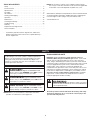 2
2
-
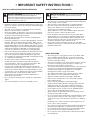 3
3
-
 4
4
-
 5
5
-
 6
6
-
 7
7
-
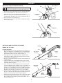 8
8
-
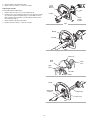 9
9
-
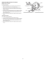 10
10
-
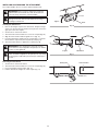 11
11
-
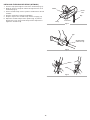 12
12
-
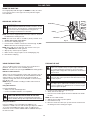 13
13
-
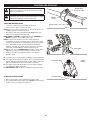 14
14
-
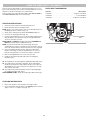 15
15
-
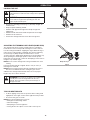 16
16
-
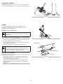 17
17
-
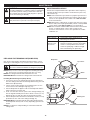 18
18
-
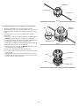 19
19
-
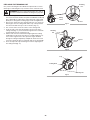 20
20
-
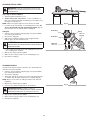 21
21
-
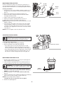 22
22
-
 23
23
-
 24
24
-
 25
25
-
 26
26
-
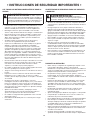 27
27
-
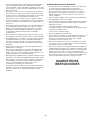 28
28
-
 29
29
-
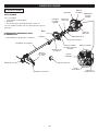 30
30
-
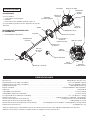 31
31
-
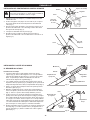 32
32
-
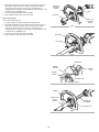 33
33
-
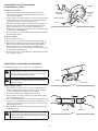 34
34
-
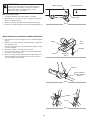 35
35
-
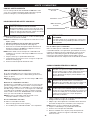 36
36
-
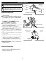 37
37
-
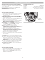 38
38
-
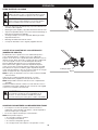 39
39
-
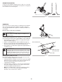 40
40
-
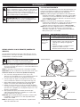 41
41
-
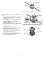 42
42
-
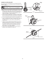 43
43
-
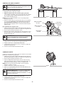 44
44
-
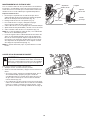 45
45
-
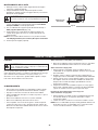 46
46
-
 47
47
-
 48
48


Craftsman 316740930 El manual del propietario
- Categoría
- Podadoras de césped
- Tipo
- El manual del propietario
- Este manual también es adecuado para
En otros idiomas
- English: Craftsman 316740930 Owner's manual
Documentos relacionados
Otros documentos
-
Troy-Bilt 41ADZ63C766 Manual de usuario
-
-
 Troy-Bild TB635 EC Manual de usuario
-
-
-
-
DeWalt DXGST227SS Manual de usuario
-
