
Owner's Manual
Manual del Propietario
®
HEAT / COOL AIR CONDITIONER
EICALOR / REFRESCA ACONDICIONADOR
DE AIRE DE VENTANA
Model, Modelo 580.72124_
Sears, Roebuck and Co., Hoffman Estates, IL 60179 U.S.A.
www.sears.com

TABLE OF CONTENTS ........................2
WARRANTY ..............................................2
SAFETY .....................................................3
Important Safety Instructions ...................... 3
ELECTRICAL REQUIREMENTS .......4
INSTALLATION ........................................ 5
Installation Requirements ......................... 5
Installation................................................ 6
How to Install............................................ 6
Removalfrom Window ................................. 8
OPERATION .............................................9
How and Why ........................................... 9
Normal Sounds ........................................ 9
Capacity and Running Time ..................... 9
Features ................................................. 10
Using the Air Conditioner ....................... 10
Air Conditioner Features ........................ 11
MAINTENANCE .....................................12
Air Filter Cleaning ................................... 12
Air Conditioner Cleaning ........................ 12
How to Remove the Front Grille.................. 12
How to Replace the Front Grille ............. 12
TROUBLESHOOTING .........................13
Before Calling for Service ...................... 13
REPAIR PARTS .....................................14
ESPAI_IOL ................................................24
SERVICE NUMBERS ............BackCover
FULL ONE YEAR WARRANTY ON
HEAT / COOL AIR CONDITIONER
For one year from the date of purchase, when this
air conditioner is operated and maintained for
normal room cooling according to instructions in this
owner's manual, Sears will repair this air
conditioner, free of charge, if defective in material or
workmanship.
FULL FIVE-YEAR WARRANTY ON
SEALED REFRIGERATION SYSTEM
For five years from the date of purchase, when this
air conditioner is operated and maintained for
normal room cooling according to instructions in this
owner's manual, Sears will repair the sealed
refrigeration system (consisting of refrigerant,
connecting tubing, and compressor), free of charge,
if defective in material or workmanship.
WARRANTY SERVICE IS AVAILABLE BY
CONTACTING SEARS SERVICE AT
1-800-4-MY-HOME ®
Warranty coverage applies only to air conditioners
used for non-commercial, private household
purposes.
This warranty applies only while this product is in
use in the United States.
This warranty gives you specific legal rights, and
you may also have other right which vary from state
to state.
Sears, Roebuck and Co., D/817WA,
Hoffman Estates, IL 60179 U.S.A.
-2-

IMPORTANT SAFETY INSTRUCTIONS
The safety instructions below will tell you how to use your room air conditioner to avoid harm to yourself or
damage to your ROOM AIR CONDITIONER.
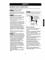
FOR YOUR SAFETY
Do not store or use gasoline or other flammable
vapors and liquids in the vicinity of this or any other
appliance. Read product labels for flammability and
other warnings.
PREVENT ACCIDENTS
To reduce the risk of fire, electrical shock, or injury
to persons when using your air conditioner, follow
basic precautions, including the following:
• Be sure the electrical service is adequate for the
model you have chosen.
• If the air conditioner is to be installed in a window,
you will probably want to clean both sides of the
glass first. If the window is a triple-track type with a
screen panel included, you may want to remove
the screen completely before installation.
• Be sure the air conditioner has been securely and
correctly installed according to the separate
installation instructions provided with this manual.
Save this manual and installation instructions for
possible future use in removing or reinstalling this
unit.
• Use gloves when handling the air conditioner.
Be careful to avoid cuts from sharp metal fins on
front and rear coils.
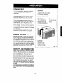
ELECTRICAL INFORMATION
The complete electrical rating of your new room air
conditioner is stated on the serial plate. Refer to the
rating when checking the electrical requirements.
• Be sure the air conditioner is properly grounded.
To minimize shock and fire hazards, proper
grounding is important. The power cord is
equipped with a three-prong grounding plug for
protection against shock hazards,
• Your air conditioner must be plugged into a
properly grounded wall receptacle. If the wall
receptacle you intend to use is not adequately
grounded or protected by a time delay fuse or
circuit breaker, have a qualified electrician install
the proper receptacle.
• Do not run air conditioner with a protective
covering. This could result in mechanical damage
within the air conditioner.
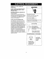
• Do not use an extension cord or an adapter
plug.
_void fire hazard or electric shock.
Do not use an extension cord or an adapter plug.
Do not remove any prong from the power cord.
Grounding type
wall Do not under any |
circumstances cut,
J
remove, or bypass
the grounding prong
from this plug.
Power supply cord
with 3-prong _,
grounding plug _\
ENERGY SAVING IDEAS
• The capacity of the room air conditioner must fit
the room size for efficient and satisfactory
operation.
• Install the room air conditioner on the shady side
of your home. A window that faces nodh is best
because it is shaded most ofthe day.
• Do not block air flow inside with blinds, curtains, or
furniture, or outside with shrubs, enclosures, or
other buildings.
• Close the floor and wall registers and the fireplace
damper so cool air does not escape up the
chimney and into the duct work.
• Keep blinds and drapes in other windows closed
during the sunniest part of the day.
• Clean the air fitter as recommended in the
MAINTENANCE section of this manual.
• Proper insulation and weather stripping in your
home will help keep warm air out and cool air in.
• External house shading with trees, plants or
awnings will help reduce the air conditioner's work
load.
• Operate heat producing appliances such as
ranges, washers, dryers, and dishwashers during
the coolest part of the day.
-3-

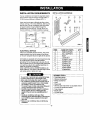
OBSERVE ALL LOCAL CODES AND
ORDINANCES.
DO NOT, UNDER ANY CIRCUMSTANCES,
REMOVE THE POWER SUPPLY CORD
GROUND PRONG.
ELECTRICAL GROUND IS REQUIRED ON
THIS APPLIANCE.
A 250-volt 60 Hz, AC only, 20A fused and
properly grounded electrical supply is required.
A time delay fuse or time delay circuit breaker
is recommended. Use a dedicated circuit,
serving only this appliance.
DO NOT USE AN EXTENSION CORD.
RECOMMENDED GROUNDING METHOD
For your personal safety, this appliance must
be grounded. This appliance has a power
supply cord with a 3oprong grounding plug. To
minimize possible shock hazard, the cord must
be plugged into a mating grounding type wall
receptacle and grounded in accordance with
the National Electrical Code (ANSI/NFPA 70)
latest edition and all local codes and
ordinances. If a mating wall receptacle is not
available, it is the personal responsibility and
obligation of the customer to have a properly
grounded 3-prong wall receptacle installed by a
qualified electrician.
_WARNING
Electrical Shock Hazard
Plug into a grounded 3 prong outlet.
Do not remove ground prong.
Do not use an adapter.
Do not use an extension cord.
Failure to follow these instructions can result
in death, fire, or electrical shock.
Line Cord Plug
_fDo not, under any ]
!i_:_'_ _Ff circumstances, cutor
3_ _::_Y remove the grounding prong I
from the plug. J
II Power supply cord with
3-prong grounding plug
Use Wag Receptacle Power Supply
Standard 250V,
3-wire grounding
receptacle rated
20A, 250V AC
Use 20 AMP,
time delay fuse
or circuit
breaker.
-4-

INSTALLATION REQUIREMENTS
Your air conditioner will install into standard double
hung windows with actual clear opening widths of
27 to 39 inches (686mm to 990mm) (FIG. t).
Lower sash must open sufficiently to allow a clear
vertical opening of 16 inches (406mm). Side louvers
and the rear of the air conditioner must have clear
air space to allow enough airflow through the
condenser for heat removal, The rear of the unit
must be outdoors, not inside a building or garage.
L _ -Sas,
27,,o39,,d!
/ ':, . |1 _ Window
[ 1161m,n. innersillLl_ Offset
Interiorwa_ll"'4 . _," FIG. 1
ELECTRICAL SERVICE
Check your available electrical service, The power
supply available must be the same as that shown
on the unit nameplate (found on right side of cabinet).
All models are equipped with a 3-prong service plug
to provide proper service and safe positive
grounding. Do not change plug in any way. Do not
use an adapter plug. If your present wall outlet does
not match your plug, call a qualified electrician to
make the necessary corrections.
SAVE CARTON and this OWNER'S MANUAL for
future reference. The carton is the best way to store
unit during winter or when not in use.
INSTALLATION HARDWARE
FIG. 2
ITEM
A
B
C
D
E
F
--G
H
I
--j
NAME OF PARTS Q'TY
SIDE CURTAIN 2
SILL SUPPORT 2
BOLT 2
LOCK NUT 2
SCREW: 25/64" 13
SCREW: 5/8" - 3
SCREW: 5/8" 5
FOAM SEAL 1
FOAM STRIP 1
L BRACKET 1
To avoid risk of personal in ury, property damage,
or product damage due to the weght of th s
device and sharp edges that may be exposed:
•Air conditioners covered in this manual pose an
excessive weight hazard. Two or more people
are needed to move and install the unit.
To prevent in ury or strain, use proper lifting and
carrying techniques when moving unit.
•Carefully inspect location where air conditioner
will be installed. Be sure it will support the
weight ofthe unitover an extended period of
time.
•Handle air conditioner with care. Wear
protective gloves whenever lifting or carrying the
unit. AVOID the sharp metal fins of front and
rear coils.
• Make sure air conditioner does not fall during
installation.
REQUIRED TOOLS:
• Tight Fitting gloves
• Standard screwdriver
• Phillips screwdriver
• Pliers
• Sharp knife
• 3/8-inch open end wrench or adjustable wrench
• 1/4-inch hax socket and ratchet
• Tape measure
• Electric drill
• t/4-inch drill bit
-5-

INSTALLATION
Pick a location which will allow you to blow the cold air
into the area you want. Windows used for installation
must be strong enough to support the weight of the air
conditioner. Good installation with special attention to
the proper position of the unit will lessen the chance
that service will be needed.
When cooling more than one room, installationlocation
is very important. If air conditioner is blocked by a storm
window frame, see step 19 on page 8 before beginning
toinstall. To cool a room, cold air must be blown from
the air conditioner in a straight path into the room.
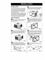
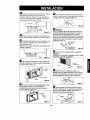
HOW TO INSTALL
_1 Remove the screws which fasten the cabinet at
both sides and at the back. Save side screws.
Discard back screws.
B Slide the unit out of the cabinet by gripping the
base pan handle with one hand, and pulling it
forward while bracing the cabinet with your other
hand.
FIG. 4
I_Jl Cut the FOAM STRIP (ITEM I) to fit the
underside of the window sash. Peel off the backing
and attach the FOAM STRIP as shown in Fig. 5.
L_ Insert the side curtain (ITEM A) into the upper
guide and lower guide of the air conditioner. Fasten
the curtains to the unit with screws (ITEM E).
FIG, 6
I_'_ Open the window. Mark a line on center of the
window inner sill. Carefully place the cabinet on the
window inner sill and align the center of the cabinet
front with the center line marked on the window
inner sill.
Windowinnersill
FIG. 7
r_ Pull the bottom window sash down behind the
upper guide untilthe sash rests on the cabinet top.
NOTE: Do not pull the window sash down so tightly
that the movement of side curtain is restricted.
Windowsash
Cabinet
S_ Curtain
_rguide
FIG. 8
_'_ Loosely assemble the sill supports using the
parts in FIG. 9.
FIG. 5
INDOOR_ _ OUTDOOR
--
_ I MB
C_ _" _ITEM D
ITEM
FIG. 9
-6-

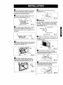
Ir_ Select the position that wirl place the sill supports
near the outermost point on sill (FIG. 10). Attach the
sill supports to the cabinet track hole closest to the
selected position using screw (ITEM E).
I_ Place the sill supports with the cabinet on the
window sirl's selected position (FIG. 10).
IIEM E
L°wer g ude s. " '_
FIG. 10
_Pi] The cabinet should be installed with a very slight
tilt (about 1/4") downward to the outside (FIG. 11).
Adjust the bolts and the nuts of sill supports to level
the cabinet.
ITEMB FIG. 11
_] Attach the cabinet to the inner sill by driving the
screws (ITEM F) through the front lower guide into
the window inner sill. (FIG. 12)
Track
ITEM B
Lower Guide
ITEM F
FIG. 12
_1 Pull each side curtain fully to each side of
window opening. Attach each side curtain to the
window sash using screws (ITEM G). (FIG. 13)
_] Attach the L bracket (ITEM J) with screw
(ITEM G) (FIG. 14).
iTEM G
ITEM J
FIG. 14
IL_JDRAINAGE
Be sure to insert the drain pipe into base pan before
installation. The air conditioner must be installed
with a slight tilt downward to the outside for proper
water drainage (FIG. 15).
_----BASE PAN REAR
DRAIN_
BASE PANBOTFOM FIG. 15
_J Slide the air conditioner into the cabinet. (FIG. 16)
CAUTION: For secudty purposes, reinstall side screws
'ou removed in step 1.
Power
Cord
Screw
_Jcut the foam seal (ITEM H) to the proper
length and insert between the upper window sash
and the lower window sash. (FIG. 17)
FIG, 17
l/ JigIThe III ventcontro,hand,emustbesfra,ghtenedF,G.+8
before the decorative front is attached.
_'_1 __ Pull down part _)to align with part_).Part_)
._i- FIG. 13 _ \"J_22 IlL
-7-

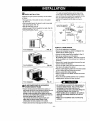
_] FRONT INSTALLATION
Installthe front grille (packedseparately) ontothe cabinet
asfollows:
• Hookuppertabs offront grille into slotson the cabinet
top. (FIG. 19)
• Push front grillelowards the cabinet inorder to snap side
tabs intothe cabinet. (FIG. 19)
• Open the inlet grille. (FIG.20)
• Installthe screw (ITEME) throughthe front grille. (Fig. 20)
• Close the inlet grille. (Fig.21)
Front Installation FIG. 19
Front Installation FIG. 20
Front Installation FIG. 21
_]IF AIR CONDITIONER IS BLOCKED BY
STORM WINDOW FRAME
• If stormwindow presents interference,fasten a 2"
wide wood strip to the inner window sill across the full
widthof the sill. The wood strip shouldbe thick
enough to raise the height of the window sill so that
the unit can be installed withoutinterference from the
the storm window frame. See FIG. 22.
Top of wood strip should be approximately 3/4"
higher than the stormwindow frame to help
condensation to drain propedy to the outside.
• Install a second wood strip (approximately 6" long by
1_/2"wide and same thicknessas first strip) in the
center of the outer sill flush against Ihe back of the
inner sill. Screw the L bracket (not supplied) into this
strip. To support the lower guide, screw an "L"
bracket (nol supplied) into this strip as shown in
FIG. 22.
1 1/2" rnin
WOOD STRIP MOUNTED _, (38turn)
ON TOP OF INNER SILL 3/4"
"- . CLEARANCE
STORM
--" W_NDOW
INNER FRAME
SILL
OUTER
SILL
I TSIDE
FiG. 22
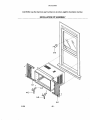
REMOVAL FROM WINDOW
• Turn off and unplug the air conditioner,
• Removethefront grille.See HOW TO REMOVE THE
FRONT GRILLE. Referto page12.
• Unscrewthe sidescrewsthatyou installedin Step 15.
• Slide theair conditioner outofthe cabinet.
BE CAREFUL NOT TO DROP IT, Holdonto itfirmly the
wholeway sJidingitout.Onceremoved, set it safetyout
ofthe way.
• Removethe Lbracket from windowframeandthe sash
seal frombetweenthe windows.
• Unscrew the side curtains from the window frame. Fold
them back to the sides of the cabinet.
• Remove screws attaching cabinet to inner sill. Be careful
not to let cabinet fall once screws are removed.
• Remove cabinet from window opening.
• Place air conditioner intocabinet. Reinstall side screws
and Front Grille.
• Place unit and all assembly hardware in air conditioner
shipping cation, and store in clean, dry place.
•Airconditioners coveredinthismanual posean
excessive weight hazard. Two or more people
are needed to move and install the unit.
To prevent injuryor strain, useproper liftingand
carrying techniqueswhenmoving unit.
•When handlingthe airconditioner,be carefulto
avoid cuts from sharp metal fins on front and
rear coils.
• Make sureair conditioner does not fall during
removal.
-8-

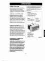
HOW AND WHY
Your room air conditioner provides the following
functions to make hot weather living more
comfortable:
• Cools and circulates room air.
• Lowers humidity by removing excess moisture.
• Filters out summertime dust, dirt, and some
airborne impurities.
The air conditioner performs these functions by
drawing room air through a filter which traps dust
and dirt particles. The air then passes over a
cooling coil which refrigerates the air and removes
excess moisture. The same air is then returned to
the room- cooler, drier, and cleaner. Moisture
removed from the room air is carried to the outside
and evaporated.
Your air conditioner is designed to be easy to
operate and to provide plenty of cooling power.
NORMAL SOUNDS FIG.23
Aside from the regular fan motor and compressor
sounds coming from your air conditioner, you will
once in a while hear a pinging sound. This is the
result of moisture being picked up from the air in the
room and thrown against the air conditioner's fan.
This is normal and should not be cause for concern.
Also, do not be alarmed if you hear a slight hissing
or gurgling sound coming from your air conditioner
after it is off. These are normal coolant noises.
-Compressor
The modern high efficiency
compressor may have a high
pitched hum or pulsating
noise that cycles on and off.
-- Unit Vibration
The unit may vibrate
and make noise
because of poor wall
or window construction.
You may hear
droplets of water
hitting the condenser
causing a pinging or
clicking sound.
Fan
You may hear air
movement from
the fan.
FIG. 23
CAPACITY AND RUNNING TIME
Proper unit size is important in deciding the desired
comfort for the area you want to cool. An undersized
unit will not have the capability to cool, leaving the
area uncomfortably warm. The proper size is
determined by the number of square feet in the area
to be cooled, indoor and outdoor temperature and
humidity.
Whenever the heat or humidity load is above normal
the air conditioner must run longer and more often to
keep the desired temperature you have selected,
Under heavy heat load conditions the air conditioner
may need to run constantly to keep the temperature
you want.
At times using the MED FAN setting to circulate the
room air may make it comfortable even though the
air is not being cooled. This will decrease your cost
of use.
-9-

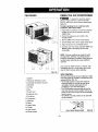
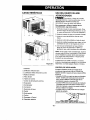
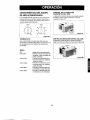
FEATURES
t t
1 14 5 4 6 3 13
I
16 8 15 7 10 11 12
FIG. 24
1. Cabinet
2. Vertical Air Direction Louvers
3. Horizontal Air Direction Louvers
4. Inlet Grille
5. Air Filter
6. Knob
7. Power Cord
8. Evaporator Coil
9. Condenser
10. Compressor
11. Base pan
12. Brace
13. Upper Guide
14. Curtain
15. Vent Control
16. Electric Heater
USING THE AIR CONDITIONER
To reduce the risk of fire, electric
shock, or injury to persons, read the important
SAFETY instructions section before operating this
appliance.
To begin operating the air conditioner after
installation, follow these steps:
1. Plug in the air conditioner. (To prevent electrical
hazards, do not use an extension cord or an
adapter plug.)
2. Push in the exhaust air vent control to the
CLOSE position.
3. Set the TEMP Control to the coolest setting.
4. Set the MODE control at the highest COOL level.
5. Adjust the louvers for comfortable air flow,
6. Once the room has cooled, adjust the TEMP and
MODE control to the setting you find most
comfortable.
NOTE : Ifthe air conditioner isturned off, wait 3
minutes before restarting. This allows pressure
inside the compressor to equalize. Failure to wait 3
minutes before restarting may cause inefficient
operation.
If you move the TEMP Control to a warmer, then
immediately back to a cooler setting, the unit will
shut off. Wait 3 minutes before restarting.
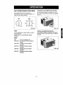
VENT CONTROL
The Vent Control allows the air conditioner to either
recimulate inside air (CLOSE) or exhaust air to the
outside (OPEN). (FIG. 25)
• The CLOSE position is used when maximum
cooling is desired. It may also be used for air
recirculation without cooling when the air
conditioner is set in the FAN position.
• The OPEN position removes stale air from the
room and exhausts itto the outside. Fresh air is
drawn intothe room through normal air passages
found in homes,
• The OPEN or CLOSE position can be used with
any fan selection.
PULL OPEN / PUSH CLOSE
FIG. 25
-10-

AIR CONDITIONER FEATURES
The controls featured in this manual are
representative of the many models available, Your
model may look slightly different.
HORIZONTAL AIR DIRECTION CONTROL
The horizontal air direction isadjusted by moving
the vertical louvers rightand left with your fingertips.
(FIG. 27)
TEMP
5
MODE
OFF
FAN FA_
O_L¥ ONLy
L_ _OOk _
_l CCX_
H_3H HIGH
H
FIG. 26
TEMP
Turnthe TEMP dial to a higher number for a cooler
room temperature.
Position 5 or 6 is a normal setting for average
conditions.
MODE
OFF
FAN ONLY
LOWCOOL
HIGHCOOL
LOWHEAT
HIGHHEAT
:Turns air conditioner off.
: Fan operation without cooling or
heating.
: Cooling with low fan speed
operation.
: Cooling with high fan speed
operation.
: Heating with low fan speed
operation.
: Heating with high fan speed
operation.
FIG. 27
VERTICAL AIR DIRECTION CONTROL
The vertical air direction is adjusted by moving the
horizontal louvers up and down with your fingertips.
(FIG. 28)
FIG. 28
-11 -

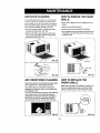
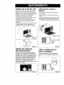
AIR FILTER CLEANING
The Air Filter will become dirty as it removes dust
from the inside air. It should be washed at least
every 2 weeks. If the Air Filter remains full of dust,
the air flow will decrease and the cooling capacity
will be reduced, possibly damaging the unit.
• Pull the inlet grille forward, grasping both tabs,
then pull out the air filter. (FIG. 29)
• Wash the Air Filter under the faucet with warm
water. Be sure to shake off all the water before
replacing the filter. (FIG. 30)
HOW TO REMOVE THE FRONT
GRILLE
• Remove the TEMP knob and the MODE knob by
pulling.
• Open the inlet grille downward.
• Remove the screw securing the Front Grille.
• Push the grille up from the bottom and pull the top
of the grille away from the case to lift the top tabs
out of their slots.
FIG. 29
FIG. 30
AIR CONDITIONER CLEANING
Clean the front grille and inlet grille by wiping with a
cloth dampened in a mild detergent solution.
The cabinet may be washed with mild soap or
detergent and lukewarm water, then polished with
liquid appliance wax.
To ensure continued peak efficiency, the condenser
coils (outdoor side of unit) should be checked
periodically and cleaned if they become clogged
with soot or dirt from the atmosphere. Brush or
vacuum exterior coils to remove debris from fins.
FIG, 31
HOW TO REPLACE THE
FRONT GRILLE
Attach the front grille to the cabinet by inserting the
tabs on the grille into the slots on the front of the
cabinet. Push the grille in until it snaps into place.
FIG. 33
-12-

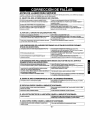
BEFORE CALLING FOR SERVICE
Check the following list to be sure a service call is really necessary. A quick reference to this manual may
help you avoid an unneeded service call
THE AIR CONDITIONER WILL NOT OPERATE
Check if,., Then.,.
Wallplug disconnected. Pushplugfirmlyinto wall outlet
oose fuse blown orcircuri breakertripped. Replacefuse withtime delaytype or reset circuit breaker.
ODE selector isOFF position. I Turn MODE selector tothe desired COOL setting. __
_--Unitwas turned off and thenon too quickly. J Turn unit offand wait 3minutes before restarting
ITEMP Control set warmer than roomtemperature. J Turn TEMP Control cklckwise to a cooler setting (higher number).
AIR FROM UNIT DOES NOT FEEL COLD ENOUGH.
Check if... Then...
MODE selector in LOW COOL position, i Turn selector to HIGH COOL position
TEMP Control set too warm (lowernumber), t Turn TEMP Control clockwise to a cooler setting (highernumber1.
Room temperature below 70°F (21°C). Coolingmay notOCCuruntilroom temperature rises above70°F (21°C).
Temperatureseosiogtubetoechingevaporatorcoil,locatedbehindfront grille. I Straighten tube away from evaperator ooil.
THE AIR CONDITIONER COOLING, RUT ROOM IS TOO WARM - ICE FORMING ON COOLING COIL BEHIND FRONT GRILLE.
;heck if,.. Then,..
Outdoor temperature below 70°F (21°C). To defrost the coil, setselectorto FAN position.Then, turn TEMP control ]
counterclockwise to awarmer setting (lowernumber).
Airfilter may bedirty. Clean filter. Refer to Maintenance sectbn of owners manual.To defrost,
set selector to FAN position.
TEMP Control set toocold for night-time cooling. Todefrostthecoil,set selectortoa FANposition._en, cottheMODE
controlatFANposltio_or"HighCool"withtheTEMPcontroltoawarmerposffion.
THEAIRCONDITIONERCOOLING,BUTROOMISTOOWARM.
Check if..,
Oirly airfilter- air restricted.
TEMP Control set toowarm.
Front of unit isblocked by drapes, blinds,furniture,
etc. Airdistributionis restricted.
Doors,windows, re(jisters, etc. open.Cold airescapes.
Unit recentlytumed on in hot room.
Then...
Cleanairfilter,RefertoMaintenancesectionofowner'smanual.
TurnTEMPcontrolcleckwisetoacoolersetting(highernumber).
Clearblookag_
Close doors, windows,re_isters,etc,
Allowadditionaltimoto removestoredheatfromwells,Ceiling,floor,andfurniture.
THE AIR CONDITIONER TURNS ON AND OFF RAPIDLY.
Check If... Then.,.
[ Outside temperatureisextremely hot. I Set MODEon HiGH speed to bring airpest cooling coilsfaster. I
NOISE WHEN UNIT IS COOLING.
Check If,,. Then...
Seundoffan hlttin_water- fromthemoistureremovals,/stom, This is normalwhen humidityis high.Close doors, windows,and registers.Windew vibration - poor iostallation. I Referto installationlestructions or check with installer. I
WATER DRIPPING INSIDE ROOM WHEN UNIT IS COOLING.
Check if,,. Then,,.
I The air cendltioner is imprcperly installed. I Tilt air conditioner sligh_ to the outside toallow water drainage. Referto
1
installationinstructions or check withinstaller, j
WATER DRIPPING OUTSIDE WHEN UNIT IS COOLING.
Check if... Then...
I The unitis rem°_ng largequantities °f meisture Ifromhumidroom. t This is normaldudngexsessivety humid days.
-13-

Room Air Conditioner To order Parts call Toll Free
Model No. 580.72124200 1-800-4-MY-HOME®(1-800-469-4663)
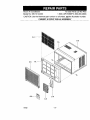
CAUTION: Use the Kenmore part number on all orders, not the illustration number.
CABINET & FRONT GRILLE ASSEMBLY
2-A
3-A
4-A
5-A
01/02 - 14 -

580.72124200
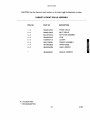
CAUTION: Use the Kenmore part number on all orders, not the illustration number.
CABINET & FRONT GRILLE ASSEMBLY
POS. NO PART NO DESCRIPTION
1 - A 3530AR1278A FRONT GRILLE
2 - A 3530AR1535A INLET GRILLE
3 - A 5231AR1152A AIR FILTER ASSEMBLY
4 - A 5990AR2974C VANE
5 - A 4758AR7211A LOUVER
6 - A 3091A10032H CABINET ASSEMBLY
7 - A 4974AR3262G UPPER GUIDE
8 - A 3850A20423M LABEL, ENERGY
3828A20292A
MANUAL OWNER'S
# = Functional Parts
* = Non-illustrated Parts
- 15 - 01/02

580.72124200
CAUTION: Use the Kenmore part number on all orders, not the illustration number.
CONTROL BOX ASSEMBLY
;I
1-B
11-B
IO-B
01/02 - 16 -

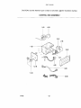
580.72124200
CAUTION: Use the Kenmore part number on all orders, not the illustration number.
CONTROL BOX ASSEMBLY
POS. NO PART NO DESCRIPTION
1 - B 4994AR1494A
2 - B # 6120AR2359D
3 - B 4H00442F
4 - B # 2H00677U
5 - B # 2H01127B
6 - B # 2H00598F
7 - B 4004AR4357A
8 - B 3550AR7032A
9 - B 6631AR2667E
10 - B 6631AR2687L
11 - B 4941AR7134E
12 - B 3721A20045P
CONTROL BOX
CAPACITOR
CAPACITOR CLAMP
POWER CORD ASSEMBLY
THERMOSTAT
ROTARY SWITCH
HOLDER PC
COVER, CONTROL BOX
CONNECTOR ASSEMBLY
CONNECTOR ASSEMBLY
KNOB ASSMEBLY
CONTOL PANEL
# = Functional Parts
* = Non-illustrated Parts
- 17 - 01/02

580.72124200
CAUTION: Use the Kenmore part number on all orders, not the illustration number.
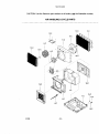
AIR HANDLING & CYCLE PARTS
13-C
14-C 3-C
12-C
8-C
10-C
19-C
10-C
/
/
I-C
15-C
17-C
16-C
01/02 - 18 -

580.72124200
CAUTION: Use the Kenmore part number on all orders, not the illustration number.
AIR HANDLING & CYCLE PARTS
POS. NO PART NO DESCRIPTION
1 - C 3041AR1524F BASE PAN WELD ASSEMBLY
2 - C 5238AR1499B AIR GUIDE
3 - C 3530AR2688D REAR WIRE GRILLE
4 - C 4900AR7024B VENTILATION DAMPER
5 - C 4960AR6165A MOTOR MOUNT
6 - C # 4681A20009M MOTOR ASSEMBLY
7 - C 3072AR1498A SCROLL
8- C # 5834AR1495B FAN ASSEMBLY, BLOWER
9 - C # 5900AR1173A FAN
10 - C 3H02932B CLAMP SPRING
11 - C 4998AR1496A SHROUD
12 - C 4810AR7029A BRACE
13-C # 5421AR6086B EVAPORATOR ASSEMBLY
14 - C # 5403AR2921A CONDENSER ASSEMBLY
15 - C 4H02023A DRAIN RUBBER
16 - C 4H01029D WASHER RUBBER
17 - C 3H02773A DRAIN PIPE
18 - C 4790AR1493A BARRIER
19 - C 5301AR7267B HEATER ASSEMBLY
# = Functional Parts
* = Non-illustrated Parts
- 19 - 01/02

580.721242OO
CAUTION: Use the Kenmore part number on all orders, not the illustration number.
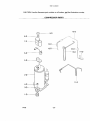
COMPRESSOR PARTS
15-D
8-D _ 9-D 1
12-D
I
6-D % 10-D [_
5-°
1-D
2-D
4-D
3-D
11-D
01/02 - 20 -

580.72124200
CAUTION: Use the Kenmore part number on all orders, not the illustration number.
COMPRESSOR PARTS
POS. NO PART NO DESCRIPTION
1- D 4830AR4335A
2- D # 5416A20012D
3- D 4H01811C
4- D 1NHA0801206
5- D 4986U-L001G
6- D # 6750U-L033A
7- D 3550U-L004A
8- D 4H01058A
9-D 4H00947A
10-D 5211AR2930A
11- D 5211AR6081A
12-D 5210AR7062A
13-D 5210AR7063A
14- D 5211AR7059W
15-D 5425AR7133T
16- D 5851A30001F
ISOLATOR, COMP
COMPRESSOR
BRACKET, WASHER
HEXAGON NUTS
GASKET
OVERLOAD PROTECTOR
TERMINAL COVER
GASKET NUT
TERMINAL COVER NUT
TUBE ASSEMBLY DISCHARGE
TUBE ASSEMBLY SUCTION
TUBE, EVAPORATOR
TUBE, EVAPORATOR
TUBE ASSEMBLY CONNECTOR
TUBE ASSEMBLY CAPILLARY
DRIER ASSEMBLY
# = Functional Parts
* = Non-illustrated Parts
- 21 - 01/02

580.72124200
CAUTION: Use the Kenmore part number on all orders, not the illustration number•
INSTALLATION KIT ASSEMBLY
2-E
01/02 - 22 -

580.72124200
CAUTION: Use the Kenmore part number on all orders, not the illustration number.
INSTALLATION KIT ASSEMBLY
POS. NO PART NO DESCRIPTION
1 - E 4959AR3402C SIDE CURTAIN ASSEMBLY
2 - E 4959AR3402D SIDE CURTAIN ASSEMBLY
3 - E 4810AR3240A SILL SUPPORT BRACKET
4 - E 1BHD1004006 BOLT
5 - E 1NHC1000006 NUT
6 - E 4H01785B L BRACKET
# = Functional Parts
* = Non-illustrated Parts
- 23 - 01/02

INDICEDEMATERIAS............................. 24
GARANTfA ................................................ 24
SEGURIDAD .............................................. 25
Impodantesinstruccionesdeseguridad...-.25
REQUERIMIENTOS ELECTRICOS ......... 26
INSTALAClON ........................................... 27
Requerimientos para instalaci6n .......... 27
Installaci6n ............................................ 28
G6mo instalarlo ..................................... 28
C6mo sacar el equipo de aire
acondicionado de la ventana ................. 30
OPERACI(_N .............................................. 31
C6mo y por qu_..................................... 31
Sonidos normales.................................. 31
Capacidad y tiempode funcionamiento .-.31
Caracterfsticas ..................................... 32
Uso del equipo de aire acondicionado .,32
Caracteristicas del equipo de aire
acondicionado ....................................... 33
MANTENIMIENTO .................................... 34
Limpieza del filtro del aire...................... 34
Limpiezadelequipodeaireacondicionado-.-.34
C6mo sacar la rejillafrontal ................... 34
C6mo a reemplaza el grilleanterior ......34
CORRECCION DE FALLAS ...................... 35
AntesdeUamarparaservicio...................... 35
LISTA DE PARTES ............................. 14~23
PARA PEDIR SERVICIO .......Cubierta Trasera
GARANT[A DE UN ANO POR EL
EQUIPO DE AIRE ACONDICIONADO
DE HABITACION
Durante un afio completo a partir de la fecha de
compra, si este equipo de aire acondicionado recibe
mantenimiento y se utiliza para el enfdamiento
normar de habitaci6n seg6n las instrucciones
indicadas en este manual del propietario, Sears
reparard gratuitamente este equipo de aire
acondicionado, si tiene alg6n defecto en materiales
o fabricaci6n.
GARANT[A TOTAL DE ClNCO ANOS
POR E.LSISTEMA DE REFRIGERACI(_N
HERMETICAMENTE SELLADO
Durante cinco afios a partir de la fecha de compra,
si este equipo de aire acondicionado recibe
mantenimiento y se utiliza para el enfriamiento
normal de habitaci6n segdn las instrucciones
indicadas en este manual del propietario, Sears
reparard gratuitamente el sistema de refrigeraci6n
herm_ticamente sellado (que consiste en el agente
refrigerante, lostubos de conexi6n y el compresor),
si tiene alg=3ndefecto en materiales o fabricaci6n.
EL SERVICIO DE GARANT[A EST.&.A SU
DISPOSICI(_N CON S6LO PONERSE EN
CONTACTO EL CENTRO DE SEARS AL
1-800-4-MY-HOME ®
La proteccion de garantia cubre unicamente a los
equipos de aire acondicionado usados para uso
domestico y no para uso comerciaL
Esta garantia s61otiene validez mientras el producto
se est_ usando en los Estados Unidos.
Esta garanfia le da derechos legales especfficos y
usted puede tener otros derechos que varfan de
estado en estado.
Sears, Roebuck and Co., D/817WA,
Hoffman Estates, IL 60179 U.S.A.
- 24 -

IMPORTANTES INSTRUCCIONES DE SEGURIDAD
Las siguientes instrucciones de seguridad le indicar_m c6mo usar su equipo de aire acondicionado de
habitaci6n para evitar dafios para usted mismo y para su EQUIPO DE AIRE ACONDICIONADO.
/
POR SU SEGURIDAD
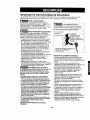
No almacene ni use gasolina u otros vapores y
liquidos inflamables cerca de _ste o cualquier otro
electrodom_stico. Lea las etiquetas de los
productos para ver si contienen advertencias sobre
el car&cter inflamable de los mismos y otras
advertencias.
PARA PREVENIR ACCIDENTES
Para reducir el riesgo de incendios, descargas
el_ctricas o lesiones personales al usar su equipo
de aire acondicionado, tome las precauciones
b_.sicas, entre las que estan las siguientes:
• Aseg6rese de que la alimentaci6n el_,ctrica sea la
apropiada para el modelo que usted ha elegido.
• Si el equipo de aire acondicionado debe instalarse
en una ventana, a usted probablemente le
conviene limpiar primero ambos lados del vidrio.
Si la ventana es del tipo de tres paneles con un
panel incluido de pantalla, le conviene sacar la
ventana completamente antes de la instalacibn.
• AsegL_rese de que el equipo de aire
acondicionado ha sido instalado correctamente y
con seguridad segt_n se sefiala en las
instrucciones separadas de instalacibn que vienen
en este manual. Conserve este manual y las
instrucciones de instalaci6n para usarlos
posiblemente en el futuro al sacar o volver a
instalar esta unidad.
• Utilice guantes al manejar el equipo de aire
acondicionado, tenga cuidado para evitar cortadas
con las afiladas aletas metalicas que se hallan en
los serpentines frontales y posteriores.
INFORMACI(_N ELECTRICA
En la placa de serie del fabricante se indica cugtl es
la capacidad el6ctrica nominal completade su nuevo
equipo de aire acondicionado para habitacibn. Consulte
esta placa cuando vaya averifP..arlos requerimientos
el_tricos.
•Asegt_resede que elequipo de aire acondidonade
tenga unaconexi6n correcta a tierra. Para reduciral
mfnimo los riesgos de descargas elL,ctdcas e incondio,
es importante conectar el equipo correctamentea tierra.
El cord6nde alimentaci6n el_[_ctdcaesta equipado con
un enchufede tres espigas con conexibn a tierra para
protegede contra riesgos de descargas elL_'tdcas.
• Su equipo de aire acondicionado debe enchufarse en
unatoma de corrientede pared que tenga unaconexi6n
correcta atJerra.Sila toma de corriente de paredque
usted piensa usar noest& conectada correctamente a
tierra o noest_ protegida con un fusible de acci6n
retardadaocon unintenuptorde circuito,hagaque un
electdeistacalifleadoleinstalelatomade cordente de
pareden forn_ correcta.
• No ponga a funcionar el equipo de aire acondicionade
con una cubierta protectora exterior endma. Esto podrfa
coasionar dafios mec_nicosdentrodel aire
acondicionado.
• No use un cable de extensi6n ni un enchufe
adaptador.
_ Evitelos peligrosdeincendiosy
descargasel_tricas. No useun cablede extensionniun
enchufeadaptador.Noelimine ningunade lasespigas
delenchufedelcord6n dealimentaci6nelectrica.
Tomadecorriente
de paredcon En ninguna 1
conexi6na tierra, circunstancia code, ]
extraigaointente
eliminarla espigade [
conexi6na tierra de este[
enchufe.
Cordon de alimentaci6n electrica con
enchufe deires espigas con
conexi6n a tierra.
IDEAS PARA AHORRAR ENERG|A
• La capacidad del equipo de aire acondicionado
debe corresponder al tamafio de la habitaci6n
para el funcionamiento eficiente y satisfaetorio del
equipo.
• Instale el equipo de aire acondicionado de
habitaci6n en el lado sombreado de su hogar. Una
ventana orientada hacia el notre es la mejor
porque tiene sombra la mayor parte del dia.
• No bloquee eHlujo de aire hacia el interiorcon
persianas, cortinas o muebles; o la parte de
afuera con arbustos, paredes u otras
construcciones.
• Cierre el regulador de tiro de la chimenea, las
rejillas de calefacci6n del piso y la pared, de tal
modo que el aire frio no se escape ni por la
chimenea ni por los conductos.
• Mantenga las persianas y las cortinas de otras
ventanas cerradas durante la parte mas soleada
del dia.
• Limpie el filtro del aire como se recomienda en la
seccibn "MANTENIMIENTO" de este manual.
• El aislamiento correeto y las juntas herm_ticas en
puertas y ventanas en su hogar le ayudaran a
mantener el aire caliente afuera y el aire frio
adentro.
• AI darle sombra extemamente a la casa con
_rboles, plantas o toldos ayudard a reducir la
carga de trabajo del equipo de aire aeondieionado.
• Opere los aparatos que producen calor como, por
ejemplo, hornos, lavadoras, secadoras y
lavaplatos durante la parte mds fria del dia.
- 25 -

RESPETE TODOS LOS C(_DIGOS Y
REGLAMENTOS.
BAJO NINGUNA CIRCUNSTANCIA CORTE,
QUITE O EVITE EL USO DE LA CONEXION
A TIERRA DE ESTA CLAVIJA.
ESTE APARATO NECESITA SER
CONECTADO A TIERRA.
Se requiere una alimentaci6n electrica CA,
adecuadamente conectada a tierra con un
fusible de 20 A, de 60 Hz y de 250 V.
Se recomienda un fusible de retardo o un
disyuntor de circuito que alimente solamente a
este aparato.
NO USE CABLE ELFtCTRICO DE
EXTENSION.
MC:TODO RECOMENDADO DE CONEXION A
TIERRA
Por su propia seguridad este aparato debe
conectarse a tierra. Este aparato viene
equipado con un cable de alimentaci6n y una
clavija de tres terminales. Para reducir al
m_.ximo el peligro de choque el_ctrico, el cable
debe estar conectado a una conexi6n de pared
con conexi6n a tierra, y esta conexi6n debe
hacerse de acuerdo con la t_ltimaedici6n del
C6digo Electrico Nacional (ANSI/NFPA 70), asf
como con los c6digos y reglamentos locales. Si
no existe una conexi6n de pared adecuada, el
cliente tiene la responsabilidad y la obligaci6n
de mandar instalar, con un electricista
calificado, una conexi6n de pared adecuada de
tres terminales con conexi6n a tierra.
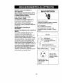
ADVERTENCIA
Peligrodechoqueel_ctrico
Conecteen unaconexi6ndeparedde 3terminales
Noquitela terminalde conexi6na tierra
Nouseadaptadores
Nousecableelectricode extensi6n
Si no sesiguenestasinstrucciones,puede
ocasionarsela muerte,un incendiooun cheque
el_ctrico,
Enchufe
JONinguna
cunstancia corte o
ueva el salida de tierra
Ienchufe
_1 Cord6n tomacorriente con
enchufe de tierra de tres salidas.
!Utilicerecibidoresdepared Energfa
Est&ndar 250V, tres
cables receptor a tierra
20A, 250V AC
nominal.
Utilice 20 AMP,
fusible de tiempo
retardado o fusible
Interruptor.
- 26

REQUERIMI.ENTOS PARA
INSTALACION
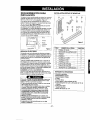
Su equipo de aire acondicionado se inslalar_,en ventanas
estandar de doble panelcon anchos de abertura libre de
686 mm a 990 rnm (27 a 39 pulgadas). (Figura 1)
Si su equipo de aire acondicienado esinstalado per la
pared, el tamano del agujero en la pared tiene que medir
15 23/_2'x 24 _/4(sin la guia superior).
El marco inferior debe abrirse Iosuficiente para permitir
unaabertura vertical libre de 406 rnm
[16 pulgadas). Las rejillasdesviadoras laterales y la parte
posterior del equipo de aire acondi¢ionado debentener
un espacio libre de aire para permitir suficiente flujo de
aire a traves del condensador para asi eliminar elcalor.
La parte posterior de la unidad debe quedar al aire libre,
no dentro de un edificio o garaje.
1_6 _==o L _ Banda
27" to 39" at I_
16" rain Ventana
Repis
I _ _.--l_'-f o Rebajo
_"_ Antepecho
_j_'_ I_; Exterior
Pared interior"'J_"/ t'' Fi ura
-...... g 1
SEBMIClO ELECTRICO
Compruebe cual es la alimentaci6n el_ctrica que Ilega a
su domicilio. La alimentaci6n el_ctrica disponible debe ser
_amismaque se muestra en la place de_fabdcante de le
unidad (que se halla en el lade derecho del gabinete de
corriente alterna).
Todos los modelos estan equipados con un enchufe de
ires espigas para sarninistrarun servicio cotrecto y una
conexion a tierra segura y positiva. No cambie el enchufe
de ningunaforma. No use un enchufe adaptador. Si su
torna de cordente de pared actual no puede usarse con el
enchufedel equipo, I_ameaun eleotdcista calificado pare
queefectee las correcciones necesadas.
CONSERVE LA CAJA y este MANUAL DEL
PROPIETARIO para que le sirva come referenciaen el
futaro. La cajaee la meier manera de censervar la anidad
durante el invierno o cuando no est_ en use.
Pareevitar el desgo de lesiones personales,danesa su
propiedad,odanes al productodebido al peso deeste
equipo yos f los aque seran expuestos:
• El aire acondicionadodel que sehabla en este manual
afirmapeligro de peso excesivo.
Doso mas personas se requierepara movere instalar
launidad. Para evitarheddaso agotamlento, use
tecnicasapropiadas pare levntary mover la unidad.
• Cuidadosamenteinspeccione el lugardondeel aire
acondicionadosere puesto. Asegurese que el lugar
sostangael peso de la unidadsobre un periodode
tiempo prolongado.
• Mantengasuaire acondicionadocon cuidado.Use
_antes protectorescuando levanteo muevala unidad.
ITElas aletas filosas de metalen elserpentin
delanteroy deatras.
• Asegurese queel aire acondicionado nose caiga
durante la instalacion.
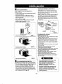
INSTALACI(_N PIEZAS DE MONTAJE
{TEM NOMBRE DE LA PIEZA CANTIDAD
A PANEL DE GUiA 2
B SOPORTE DE ANTEPECHO 2
C PERNO 2
D TUERCA 2
E TORNtLLO: 25/64" 13
F TORNILLO: 5/8" 3
G TORNILLO: 5/8" 5
H CINTA DE ESPUMA 1
I CINTA DE ESPUMA 1
J SOPORTE DE CERRADURA 1
HERRAMIENTAS REQUERIDAS
• Guantes apretados
• Destornillador normal
• Destornillador Phillips
• Pinsas
• Cuchillo filoso
• Llave inglesa o Ilave abierte de 3/8"
• Llave hexagonal de cube y trinquete de 1/4 de
pulgada
• Cinta para medir
• TaJadro electfico
• Broca de taladro de 1/4"
- 27 -

INSTALACI( N
Escojaunlugarquele permitallevarel aire frio al areaque
desea.Lasventanasquese usenpara lafnstalaci6ndeben
tenetla resistenciasuficientepara soporiare]pesodel
equipode aireacondicionado.Unabuenainstalacioncon
atenci6nespeciala la correctaposici6nde launidad
disminuif_la probabilidadde quesea necesarioefectuar
reparaciones.
Cuandose deseaenfriarmas de unahabitaci6n,la
instalaci6nesmuy imporlantesi elaireacondicionadoesta
bloquedoporun marcode la contraventanayeael paso19
enla p#=gina8antes decomenzarla instalacion,Paraenlriar
sushabitaciones,el aire trio debedesplazarsedesdeel
equipode aireacondicionadoenunatrayectoriarecta.
COMO INSTALARLO
L1 Saque los tornillos que aseguran el gabinete
en ambos lados yen la parte posterior.
Figura3
F_ Deslice la unidad sacandola de su gabinete
agarrando el asa del recipiente de la base y tirando
de ella hacia delante mientras sostiene el gabinete.
Figum4
_1 Corte la cinta de espuma (iTEM I) a la
extension apropiada.
Despegue el refuerzo y peguelo en el lado de abajo
del marco de la ventana,
_1 Inserte los paneles de guia (iTEM A) en la gufa
superior y las gufas de marco del equipo de aire
acondicionado. Sujete las cortinas en la unidad con
los tornillos (iTEM E).
Gula supelior
I
iTEM_E
Figura6
_"'_ Abra la ventana. Marque una linea en el centro
de la repisa de la ventana (o en la posici6n deseada
del equipo de aire acondicionado). Coloque
cuidadosamente el gabinete en la repisa de la ventana
y alinee la marca central en la parle frontal inferiorcon
la linea central marcada en la repisa de laventana.
Guiasuperior
_aelaventa;_gura7
r_Tire del marco inferior de la ventana hacia abajo
detras de la guia superior hasta que seencuentre la guia
con el marco.
NOTA: No tire del marco de la ventana tan hacia abajo
que quede restringido el movimiento del panel guia.
Marco de laventana /
, Guia supedor
ITEM H_I _
!:
Gabinete
(TEM A
gum 8
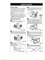
i_ Monte sin apretar el soporte de antepecho
usando las piezas indicadas en la Figura 9.
INTERIOR EXTERIOR
iTEMB
iTEM C iTEM D Figura 9
- 28 -

I_1 Seleccione la posici6n en la que colocara el soporte
de antepecho cerca del punfo mas externo en el
antepecho (Figura 10). Fije el soporte de antepecho al
orificio del carril del gabinete en relaci6n con la posicion
seleccionada usando el tornillo (ITEM E).
I_1 Coloqueelsoportede antepechoconel gabineteenla
posicionseleccionadadel antepechode ventana(Figura 10).
_1"_ El gabinete debe instalarsecon una inclinaci6n muy
ligera (cerca de 1/4pulgada, 6.35 mm) hacia abajo y
hacia fuera (Figura 11).
Ajuste el perno y la tuerca del soporte de antepecho para
equilibrar el gabinete.
Y
ITEMB Rgura 11
_1] Fije el soporte de antepecho al orificiodel carril del
gabinete en relaci6n con la posici6n seleccionada usando
el tornillo (ITEM F) (Figura 12).
marco
iTEM B
-- Guiamasbaja
\
ITEM F
Rgura 12
_1 Estire cada corlina del lado completamente a cada
lado de abrir de ventana. Fije cada panelguia
completamente a cada marco de laventana usando
tornillos (ITEM G). (Figura 13)
ITEM G
Rgura 13
- 29 -
_] Corte la cinta de espuma para que tenga la Iongitud
correcta eins_rtela entre el marco superior de la ventana
y el marco inferior de la ventana. (Figura 14)
ITEM G
Figura14
[] DRENAJE
Primero, Asegeresede insertar eltubode drenaje en el
recipientede base antesde la instalaciSn.Elequipode
aireacondicionado debeinstalarsecon unaligera
inciinaciSn haciala parleexteriorparapermitir eldrenaje
delagua.Por Io general,el equipode aireacondicionado
puededrenar el aguacondensadaa trav_sde lafuberfa
de drenaje.(Figura15)
PARTE POSTERIOR
TUBO DE DEL REC_PIENTE
DRENAJE DE BASE
PARTE INFERIOR DEL
Figura15
_"] Deslice el chasis meti_ndolo dentro del gabinete.
(Figura 16)
CUIDADO: Paragarantizar la seguridad, vuelva a instaiar
los tornillos en los lados del gabinete.
'_"___ Conrdon
Tornillo
Tomillo Figura16
_"_ Despu_sde volvera instalar launidaden el
gabinete,habrdunespaciolibreentrelacara inferiorde
launidad.yelantepechode la ventana.Use lacinta de
espuma(ITEM H) provistaparacubdresta abertura.
iTEM H
Rgura 17
_"_Se debe instalar el asa antes de montar el panel
decorativo. Antes de usar la caractefistica de ventilaci6n,
haga un kit de ventilacibn, primero, tire de la parte A
hastala linea horizontalcon laparte B.
_Parl Parte B ..,._.<1
Rgura 18

_] INSTALACI(_N FRONTAL
Instale la rejilla frontal con el gabinete de la
siguiente manera:
• Tire de la rejilla frontal hacia debajo desde la parte
superior del gabinete
• Empuje las puntas de la rejilla frontal hacia el
gabinete para insertar las leng etas de la rejilla
dentro dei gabinete.
• Abra la rejilla de entrada
• Apriete el tornillo (iTEM E) a traves de la rejilla
frontal fi _ndolo al recipiente de base
• C erre la re Ila de entrada
INSTALACI(_N FRONTAL
Figura19
INSTALAClON FRONTAL Rgura20
INSTALAClON FRONTAL
Figura 21
_]Sl EL ACONDICIONADORDE AIREESTA
BLOQUEADOPeR EL MARCODELACONTRAVENTANA
• Si lacontraventanainterfiere,fije unlist6n de maderade
2" de ancho al alf6izarintedorde laventana,que
atravieselaanchuratotaldelaff_izar.Etlist6nde
madera debeser suficientementegruesoparalevantar
la alturadel alf_izarde laventana de tal maneraque la
onidadpueda ser inatalada sin la interferencia det marco
de la contraventana. Vea la Figure22.
La parle superior del list6n de madera debe ser
aproximadamente 3/4" m&salto que el marco de la
contraventana o el list6n de madera (fuera de lacasa)
para que el vapor emanado de launidad pueda drenar
adecuadamente hacia el exterior.
• Instaleunsegundolistende madera(deaproximadamente
6" de largoy 1"de anchoy delmismogrosordelprimer
listen)enel centre delalfeizarexteriorniveladocon la
parleposteriordel alfeizarinterior.AtornillelossoportesL
entre la faja. Estolevantarael soporteLcomesemuestra
en laFigura22.
1 1/2" min.
(38rnm)
FRANJA DE MADERA _-I _ 3/4-PULG
MONTADA SOBRE _/ i DE SEPARAC_ON y
LA PARTE SUPERIOR _ -- * --
eELOESCAeS ._VENTAN eE
INTERIOR HOJA OOBLE
ANTEPECHO
INTERIOR
ANTEPECHO
ERIOR
Figura22
La ELIMINACIONDEla VENTANA
• Apagueelacondicionadoraereo.
• Quiteelgrilleanterior.VeaCOMeAREEMPLAZAELGRILLE
ANTERIOR.Refi_rasea _gina 34.
• Deetomilleeltornillodelladequeustedinstal6enelPaso15.
• Desliceelacondicionadoraereofueradelgabinete.TENGA
CUIDADOnoAlaGOTA.TengaenIofirmementelamanera
enteraquedeslizafuera.Unavezquitado,Iopusoseguridad
fueradelamanera.
• Quiteelpar_ntesisLdelmarcodeventanay elsellodebanda
deentreelwindows.
•Destornillelascorlinasdelladedelmarcodeventana.
D6blelosapoy_analosladesdelgabinete.
•Quiteeltomilloconectargabinetealalfeizalinterior.Tengacuidado
noa permiti6quegabinetefallaraunaveztomillossequitan.
• Quitegabinetedeabrirdeventana.
•Coloquestacondicionadora_reoenelgabinste.Vuelvaa
instalarlostomillosdelladey GrilleAnterior.
• Coloquelaunidady todaferreteriadelaasambleaenel
cart6naereodelenviodelacondicionador,yen la tiendaen
limpia,secaellugar.
• El aire acondicionado del que se hablaen este
manual afirmapeligro de peso excesivo.
Doso mas personas se requiere para mover e
instalar la unidad. Para evitarheridas o
agotamlenfo, use tecnicas apropiadas para
levntar y mover la unidad.
• AI manejar launidad, tenga cuidado paraevitar
eortarseconlas alertas metdlicas afiladas que
est&nen los serpentinesfrontal y posterior.
• Asegurese que el aire acondicionado no se caiga
durante la instalacion.
- 30 -

COMO Y POR QUI
Su equipo de aire acondicionado de habitacion
brinda las siguientes funciones para hacer que la
vida en climas calidos sea mAs confortable:
• Enfrfa y hace circular el aire por la habitaciSn
• Disminuye la humedad eliminando la humedad
excesiva.
• Filtra el polvo, el sucio y algunas impurezas
transportadas en el aire del clima veraniego.
El equipo de aire acondicionado realiza estas
funciones haciendo pasar el aire del medio
ambiente a trav6s de un filtro que atrapa las
particulas de potvo y sucio. El aire pasa entonces
por un serpent[n de enfriamiento que refrigera el
aire y elimina el exceso de humedad. E[ mismo aire
regresa entonces al enfriador, secador y limpiador
del aire del ambiente. La hurnedad extrafda del aire
ambiente es tlevada al exterior y evaporada.
Su aire acondicionado est& diseSado para operar y
suministrar una enorme potencia de enfriamiento.
SONIDOS NORMALES Figura 23
Adem&s de lossonidos regulates del motor del
ventilador y el compresor que salen de su equipo
de aire acondicionado, usted escuchar_ de vez en
cuando un sonido met&lico. Este sonido es
pmduciclo por la humedad que es recogida del aire
en el ambiente yes lanzada contra el ventilador del
equipo de aire acondicionado. Esto es algo normal
que no debe set motivo de preocupaci6n. De igual
modo, no se alarme si usted escucha un ligero
sonido de silbido o borboteo proveniente de su
equipo de aire acondicionado despu_s que Io
apaga. Estos son ruidos normales del refrigerante.
CAPAClDAD Y TIEMPO DE
FUNClONAMIENTO
AIdecidircueldebeserlacomodidaddeseadaparaelareaque
ustedquiereenfriar,esimportantedetenninareltama_ correcto
delaunidad.Unaunidadpequenanotendra_acapacidadpara
enfriar,dejandolaareacalurosa.EltamaSoadecuadees
determieadeporeln0merodemetroscuadradeaquetieneel
areaquesedeseaenfriar,asicomoporlatemperaturainteriory
exteriory potlahurneded.Unaunidaddernasedegrandesi
eflfria,peronodeshumedece,dejandolaareafriay humeda.
Siempfequelacargat_rmicadelventiladoresl_perendrnade
Iono_nal,elequipodeaireaosndicionadodebefunoonarmas
tJernpoparamantenerlatemperaluradeseadequeustedha
selecox)eade.Bajocondicieaesde unacargat6rmicarnuy
pesada,puedeserneceeanoqueel_luipo deaire
aceadicieaadefunooneconstantementeparamantenerla
temperaluradeseada.
Enosasiones,elusodeMEDFANparahacercircularel airepor
lahabitacionhacequeel ambienteseamasconfortableaun
cuandoel equiponoesteenfriandeel aweMientrasmastiempo
yconmayorfrecuencialuncioneelequipodeaire
acondicionade,maselectricidadeansumiraymayoresseranlos
costosdesuuea.
i ompresor
El moderno compresor de gran
eficiencia puede producir un ruido
agudo de murmullo o un ruido de
pulsacion que viene y se va.
- Vibraciones de la
unidad
La unidad puede vibrar y
hacer ruido debido a la
deficiente construcci6n
Ventilador --
Usted puede
escuchar el
movimiento del
aire proveniente
del ventilador
- Condensador
Usted puede escuchar
gotas de agua que caen
sobre el condensador
causando un sonido
metalico o unsonido de
chasquido.
Figura 23
- 31 -

CARACTERISTICAS
i
14 5 4 63
168 15 7 10 11 9 12
Figura 24
1. Gabinete
2. Deflectors vertical de aire
3. La Direcci6n A_rea horizontal Louvers
4. Rejilla de entrada
5. Filtro del aire
6. Tablero de control
7. Cordbn de alimentacibn el_ctrica
8. Evaporador
9. Condensador
10. Compresor
11. Recipiente de base
12. Puntal
13. Gufa superior
14. Cortina
15. Descargar el Control
16. Calentador eldetrico
13
USO DEL EQUIPO DE AIRE
ACONDICIONADO
_Para reducir el riesgo de incendio,
descargas electrica o lesiones personales, lea las
IMPORTANTES INSTRUCCIONES DE
SEGURIDAD antes de operar este aparato.
Para comenzar a utilizar el equipo de aire
acondicionado, siga estos paaos:
1. Enchufe el equipo de aire acondicionado. (Para
prevenir riesgos de descargas electricas, no use
un cable de extensi6n ni un enchufa adaptador.)
2. Ajuste el extractor de aire en la posici6n CLOSE.
3. Ajuste el control de MODE al mas alto nivel
fresco.
4. Ajuste el control del ventilador al m61salto nivel.
5. Ajuste las rejillas desviadoras para Iograr un flujo
confortable de aire con la lengLieta de control.
6. Una vez que la habitaci6n se haya enfriado,
ajuste el control de temperatura TEMP a la
graduaci6n que usted considere m_.sconfortable.
NOTA: Si se apaga el aire acondicionado, espere 3
minutos antes de volver a encenderlo. Esto permite
que se estabilice la presibn dentro del compresor.
Si no sigue estas instrucciones, el equipo podrfa
funcionar con poca eficiencia.
Si usted mueve el TEMP el control a un warmer,
entonces inmediatamente espalda a una colocaci6n
m_ls fresca, la unidad apagar& Espere 3 minutos.
CONTROL DE VENTILACION
Elcontroldeventilaci6npermitequeel equipode aire
acondicionadohagarecircularel aireenel interiordela
habitaclSn(CLOSE)osaqueel airehacia elexterior(OPEN).
(Figura25)
• Laposici6nCLOSEsirvecuandose deseaunenfliamiento
m_b(lmo.Tambi_npuedeusarseparahacerrecircularel
airesin enfriarla habitacibncuandeelequipode aire
acondicionadoseajustaen laposici6nFAN.
• Laposici6nOPENextraeel aireestancadode lahabitaciSn
y Ioexpulsahacialuera.El airefrescoesIlevadehaciael
interiorde lahabitaci6natray,s de lospasajesnormalesde
aim quesehallanen loshogares.
• Laposici6nOPENoCLOSEpuede usarseconcualquier
selecci6ndeventilader.
- 32 -

CARACTERiSTICAS DEL EQUIPO
DEAIREACONDICIONADO
Los controles que se explican en este manual son
representativos de muchos modelos disponibles a
ia venta en el mercado. Su modelo puede tener un
aspecto ligeramente diferente.
Figura 26
TERMOSTATO
Gire el dial TEMP al nt_mero m&s alto para una
temperatura ambiente m#.s fresca. La posicion 5 o 6
es una graduaci6n normal para las condiciones
promedios.
MODO
OFF
FAN ONLY
LOW COOL
HIGH COOL
LOW HEAT
HIGH HEAT
: Apaga el aire acondicionado.
: Permite el funcionamiento del
ventilador a baja velocidad sin
enfriar (calentar).
: Permite el enfriamiento con el
funcionamiento del ventilador
a baja velocidad.
: Permite el enfriamiento con el
funcionamiento del ventilador
a alta velocidad.
: Permite el calentamiento con
el ventilador a baja velocidad.
: Permite el calentamiento con
el ventilador a alta velocidad.
CONTROL DE LA DIRECCIC)N
HORIZONTAL DEL AIRE
La direcci6n horizontal del aire es ajuslada rotando
la palanca veilical hacia la derecha o hacia la
izquierda. (Figura 27)
Figura 27
CONTROL DE DIRECCI()N VERTICAL DEL AIRE
La direccibn vertical delaire se ajusta moviendo la
rejillahorizontalhacia delante o hacia atras.(Figura 28)
Figura 28
- 33 -

LIMPIEZA DEL FILTRO DEL AIRE
Sedebe revisar el filtro de aire al menos dos veces al
ruesparaver si es necesario limpiarlo. Las partieulas
atrapadas en elfiltro se iron acumulando hastabloquear
el flujo del aire. Esto reduce la capacidad de enfriamiento
del equipo y causa tambi_n una acumulaci6n de
escarchaen los serpentines de enfriamiento.
• Abra la rejilla de entrada de aire hacia arriba tirando de
la parte inferior de esta rejilla. (Figura 29)
• Saque el filtro del aire del conjunto de la relilla frontal
tirando ligeramente del filtro del aire hacia arriba.
(Figura 30)
• Laveel filtrodel aireen aguatibiaa menosde 104°F(40°C).
• Aseg_rese de eliminar toda el agua sacudiendo
suavemente el filtro. Vuelva a ponerlo en suposici6n.
_Figura 30
LIMPIEZA DEL EQUIPO DE
AIRE ACONDIClONADO
La rejillafrontal y la rejilla de entrada detairepueden
lavarseconun patio humedeeido enunasoluci6nde
detergente suave.Elgabinete puedelavarseconunjab6n
o detergentesuave y aguatibia,seguidamentepuede
pulirseconcera Ifquidaespecialparaelectrodom_sticos.
Paraasegurarunaeficienciamaxima continua,los
serpentinesdel condensador(el ladode la unidadque
est&expuestoa laintemperie)deben revisarse
ped6dicamentey limpiarsesiest_nobstruidosconhollin o
con suciode laatm6sfera.
Figura 31
COMO SACAR LA REJILLA
FRONTAL
• Saque la perilla delTEMP y la perilla de MODE
tirando de elias.
• Saque el tornillo que mantiene la rejilla frontal en
posici6n.
• Empuje la rejilla hacia arriba de abalo y jale la parte
de arriba de la rejilla lejos de la base para levantar
las lenguetas de arriba haeia afuera de las ranuras.
RejiUade entrada
RejUlade anterior
Figura 32
COMO A REEMPLAZA EL
GRILLE ANTERIOR
Pegue el panel frontal a la caja insertando los
fijadores en el panel adentro ras aberturas de la
caja,
Figura 33
- 34 -

ANTES DE LLAMAR PARA SERVICIO
Cheque la siguiente lista para asegurarse si en realidad es necesario Ilamar para servicio. Una referencia rapida a
este manual puede evitar una Ilamada para servicio innecesaria.
EL EQUlPO DE AIRE ACONDICIONADO NO FUNClONA.
Elenchulenoestaconectadoenlatomadecordentedepared.
Elfusibleeslaquemadeoel interruptordecocoitosehadisparado
Etselectordel ventiladorMODEestaenla pos_d_ldeOFF.
[a unidedseapag6yse volvioaencenderdemasiaderapide.
ElcontroldetemperaturaTEMPseajust6mascalidoquela
temperaturaambiente
Conecteeler_holefirmementeenlatomadecomentedepared.
Reemplaseelfusibledafiadoconsefusibledeacciedretardadaoreajusteel
interruptordedrcedo.
PongaelselectorenlapeeleldedeCOOL.
Apaguelaunidadyespere3minutosantesdevolveraencendefla.
Gireelcontroldetemperaturaenelsentidedelasagujasdelrelojhastauna
graduacbnm_sfria(numeromasalto).
EL AIRE DE LA UNIDAD NO SALE BASTANTE FRJO.
Elsetectorauseposic_nrnas LOWCOOL.
Elcort¢_detegoeeluraTEMPseafust6de'nasadoc_i.r_o(numeforres10ap)
Latemperaturaambienteeslapordebajodelos70°F (21°C)
I EItubosensordetemperaturaeelatcoandoel serpentinevaporador
queestasltuadodefrasdelfi_trodel aire.
Gireelselectora unaposielbnHIGHCOOL.
Gireelcontroldetemperaturaenelsentidodelasagu)asdelrek)jpara
Nopaedeproduelrseelenfriamientohastaquelatemperaturaambientesuba
Forencimadelos70° F{21°C).
Endereceeltuboalej#tndelodelserpentinevaporador.
ELAIREACONDICIONADOENFRiA,PEROLAHABITACI()NSESIEh'EDEMASIADOC/_UDA;SEFORMAHIELOENELSERPENTINDEENFRIAMIENTO
DET_SDELPANELDECORA'RVOFRONTAL
Latemparaturaambienteenelextedo¢estapotdebajode_ 70°F(21°C).
Elfi_trodelairepuedeestarsuelo.
Elcontroldetemperaturase ajust6demasiadofdoparael
enfriamientonoctumo.
ParadescongelarelserpentinIleveelselectorala posleionFAN.
Seguidamente,gireelcontr_detemperaturaTEMPenelsent;dodelasagujas
delre_ paraIlevariohastaunag_aedac_nm&s_lida
I..impieel filtro.C_nsultelasecol_ "Mantenimiento".Paradescongelar,Ileveel
selectoralai_sicibnFAN.
Paradeseongelarel seq_entin,Ileveelselectorala pasicideFAN
Seguidementeajueleelcontroldetemperaturaa unaposici6nm_ calide
ELAIREACONDICIONA,DOENFRiA,PEROLAHABITACIONSESENTEDEMASIADOC/_LIDA;NOSEFORMAHIELOENELSERPENT/NDE
ENFRIAMIENTODETRAS[]ELPANELDECORA11VOFRONTAL..
Elflltrodelelreest_seeloconIoqueserestringeelflujodelaire. Limpieelfiltrodelelre.Consultetasecci6n"Mantenimiemo"
ElcontreldetemperaturaTEMPsegradu6enIx_sielbndemasiadecalida. Gireelcontroldetemperaturaenolsentidodelasagujasdelrelojparatlevaltoa
sea_raduacidemLsfria.(N_merom_salto)
Laparlefrontaldela unelade_ bloqueadepotcdeises,pergar_s, Elimiseelbloqueoenfmntedelaunided.
mueblesetc,querestltngenladistdbuelonde[elre,
Lagpaertas,ventanas,rejillasde¢atefacoibn,etc_tera,_ abiertascon Cierrelaspaertas,ventanas,rejillasdecelefacel6n,etcetera.
Ioquesepermlteelescapedelelrefrel.
Launidadasebadeencenderseenunahabitael_nceliente, i Permltaquetranscunaunpocom_sde_empoparaelimiserel"caloralmacenado"
enlasparedes,eltecho,elpiseyIsemuebtes,
EL EQUIPO DEAIRE ACONDICIONADO SE APAGA Y SE ENCIENDE RAPIDAMENTE .
I'a'e pa'a oo edo'e o° ade e o'o.IIdeoflt ,a
SE ESCUCHAN RUIDOS CUANDO LA UNIDAD ESTA ENFRIANDO.
Elsenidodelven_ladorelchcoarc_ra elaguadelseltemade Eeloesnormalcuandelahumededesaita.Cierre_s puerta&ventanasyrejillas|
eliminaelbndehumedad, deselelacoi_.
tVibraci_ndelaseelana;inelabdondefldente. Leabs instn,_clenesdeinstalack_oconsultealinstelador.
EL AGUA GOTEA DENTRO DE LA HABITACI(_NCUANDO LA UNIDAD ESTA ENFRIANDO.
J,nsta_ inadecueda. I Ir_ _arnente el_upo de_ _1o I_dalapa_ exte_"p_apam_@el
d_rajedelag_. Lealasi_ deimtaladeqoconseltealinstalad_.
EL AGUA GOTEA AFUERA CUANDO LA UNIDAD ESTA ENFRIANDO.
habltael_nLaunidadeelaexfrayendog_ cantidedesdehunlededdeUnahumede. IEstoeselgonon'selduranteIcodiasexses_vamentehumedes. I
- 35 -

Get itfixed, at your home or ours!
Your Home
For repair- in your home-of all major brand appliances,
lawn and garden equipment, or heating and cooling systems,
no matter who made it, no matter who sold it!
For the replacement parts, accessories and
owner's manuals that you need to do-it-yourself.
For Sears professional installation of home appliances
and items like garage door openers and water heaters.
1-800-4-MY-HOME ® (1-800-469-4663)
Call anytime, day or night (U.S.A. and Canada)
www.sears.com www.sears.ca
Our Home
For repair of carry-in items like vacuums, lawn equipment,
and electronics, call or go on-line for the location of your nearest
Sears Parts & Repair Center.
1-800-488-1222
Call anytime, day or night (U.S.A. only)
www.sears.com
To purchase a protection agreement on a product serviced by Sears:
1-800-827-6655 (U.S.A.) 1-800-361-6665 (Canada)
Para pedir servicio de reparacion
a domicilio, y para ordenar piezas:
1-888-SU-HOGAR _
(1-888-784-6427)
Au Canada pour service en fran£_ais:
1-800-LE-FOYER Mc
(1-800-533-6937)
www.sears.ca
® Registered Trademark / _MTrademark / s_ Sen4ce Mark of Sears, Roebuck and Co.
® Marca Regist rada / TMMarca de F_lbrica/ SMMarca de Servieio de Sears, Roebuck and Co.
MCMarque de commerce / MDMarque depos_e de Sears. Roebuck and Co. © Sears, Roebuck and Co
Pa,t No.: 3828A20292A
-
 1
1
-
 2
2
-
 3
3
-
 4
4
-
 5
5
-
 6
6
-
 7
7
-
 8
8
-
 9
9
-
 10
10
-
 11
11
-
 12
12
-
 13
13
-
 14
14
-
 15
15
-
 16
16
-
 17
17
-
 18
18
-
 19
19
-
 20
20
-
 21
21
-
 22
22
-
 23
23
-
 24
24
-
 25
25
-
 26
26
-
 27
27
-
 28
28
-
 29
29
-
 30
30
-
 31
31
-
 32
32
-
 33
33
-
 34
34
-
 35
35
-
 36
36


Kenmore 580.72124 El manual del propietario
- Tipo
- El manual del propietario
- Este manual también es adecuado para
en otros idiomas
- English: Kenmore 580.72124 Owner's manual
Artículos relacionados
-
Kenmore 580.75184500 El manual del propietario
-
Kenmore 580.74054400 El manual del propietario
-
-
-
-
Kenmore 75101 10,000 El manual del propietario
-
-
-
-