Glacier Bay 78PW557PELFHD Guía de instalación
- Categoría
- Artículos sanitarios
- Tipo
- Guía de instalación

VPC0309051242
COD.: 78CC557PISTEX Rev. 00-09/05
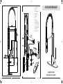
1 Lever
2 Handle
3 Cover
4 Locking nut
5 Lock screw
6 Cartridge
7 Body
8 Screw
9 Shank
10 Base ring
11 Deck plate
12 Plastic sheet
13 Flange
14 Supply tubes
15 Nipples
16 Fixing kit
17 Threaded pin
18 Antifriction ring
19 Connector
20 O-rings
21 Plastic ring
22 Chrome shields
23 Spout holder
24 Horizontal spout holder
25 Shower holder
26 Screws
27 Whasher
28 Spring
29 Hose
30 Whasher
31 No return valve
32 Spray head
33 Whasher
34 Areator
35 Areator ring
HI-TECH KITCHEN FAUCET
Istruzioni per l’installazione - Assembly instruction
Instrucciones para el montaje - Instructions pour le montage
En cas de pression dynamique supérieure à 5 bar (~75
psi), nous conseillons d’utiliser un réducteur de pression.
Avant de procéder au montage, nous vous conseillons de
purger les tuyauteries de l’eau chaude et de l’eau froide
pour éviter que saleté et résidus puissent compromettre la
marche du robinet.
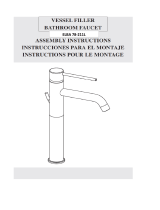
INSTALLATION DU ROBINET (Fig.1)
Introduire la tige filetée (1) et les tuyaux d’alimentation (2)
dans le corps du robinet (3).
(Fig.2) Si l’évier a 3 trous, utiliser l’habillage de 8 " : posi-
tionner l’habillage (7) sur le trou du sanitaire interposant
l’embase plastique (8).
Introduire le tuyau entretoise (4) et l’embase (5), en veri-
fiant de positionner l’o-ring (6) de façon correcte.
Introduire le robinet dans le trou du lavabo, introduire le
joint façonné (9) et la bride (10) sur la tige filetée (1).
Fermer le robinet avec le tirant (11). Pour augmenter la
stabilité du robinet utiliser la bride (13) entre le joint
façonné (9) et l’évier.
Connecter les tuyaux d’alimentation (2): le tuyau de gau-
che avec la distribution de l’eau chaude et le tuyau de droi-
te avec la distribution de l’eau froide. S’il est nécessaire,
utiliser les raccords (12).
Ouvrir l’eau et vérifier le correct fonctionnement du miti-
geur et la parfaite tenue de toutes ses parties.
MAINTENANCE ET CONSEILS
PRA
TIQUES-TECHNIQ
UES
REMPLACEMENT DE LA CARTOUCHE
(couper l’arrivée d’eau principale) (Fig.3)
Dévisser le levier (1), enlever la manette (2), dévisser le
capuchon (3) et l’embout (4) et enlever la cartouche (6).
Dévisser l’allonge de cartouche (5) et le visser sur la nou-
velle cartouche. Introduire la cartouche dans le corps du
robinet et remonter en procédant en sens inverse; s’assu-
rer de bien nettoyer les surfaces où agissent les joints.
Fermer l’embout (4) de façon qu’on puisse garantir l’étan-
chéité et en même temps un mouvement souple de la
manette.
REMPLACEMENT DES O-RINGS DU BEC (Fig.3)
Dévisser la vis (7) et sortir le bec. Remplacer les o-rings
(8) et la bague (9) s’il est nécessaire.
Pour le montage, procéder en sens inverse et s’assurer de
bien nettoyer les surfaces où agissent les joints d’étan-
chéité.
Avant de visser la vis (7), s’assurer que la bague (9) soit posi-
tionnée de façon correcte pour recevoir la vis dans la fente.
NETTOYAGE DU MOUSSEUR (Fig. 3)
Il faut procéder à l’entretien du mousseur pour éviter l’ac-
cumulation de détritus et calcaire, qui avec le temps pour-
raient causer une diminution graduelle du débit. Pour
procéder au démontage du mousseur (10), le dévisser et
nettoyer le filtre (11) des impuretés, remonter en procédant
en sens inverse et s’assurer de positionner le joint (12) de
façon correcte.
MAINTENANCE DES SURFACES
Pendant le nettoyage, la surface du robinet doit être froide
(la chaleur augmente le risque d’usure de la surface).
S’assurer que les produits pour le nettoyage ne contiennet
pas de produits acides ou abrasifs. Il faut nettoyer le robi-
net tous les jours avec un chiffon doux. Eviter pailles de fer
ou éponges abrasives. Après le nettoyage, enlever les resi-
dus de détergent avec de l’eau froide. Dommages aux
robinets causés par un nettoyage pas approprié sont
exclus de notre garantie.
Alimentation Recommandée Maximum Minimum
Température eau chaude 65 C° (~150F) 80 C° (~175F) 15 C° (~60F)
Pression dynamique 3 BAR (~45PSI) 5 BAR (~75PSI) 0.5 BAR (~7PSI)
Conditions generales d'utilisation
INSTRUCTIONS POUR LE MONTAGE
4
557ISTUSA 5-09-2005 12:06 Pagina 1
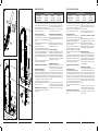
Assembly instruction
Instrucciones para el montaje
1 Complete handle
2 Cover nut
3 Blockin nut
4 Insert Cartridge GM
5 Cartridge GM
6 Screw M5
7 Base ring
8 Flange
9 Base plate
10 Complete fixing set
11 M10x1-9/16” flex tubes
12 Complete spring support
12.1 O-rings/ring connection
13 Complete hand shower
13.1 Aerator M22x1
13.2 DW15 valve 2.2GPM
AC78CC557PEISTEX

3
In caso di pressioni di esercizio superiori a 5 bar (~75 psi),
si consiglia l'uso di un riduttore di pressione. Prima di pro-
cedere al montaggio, si consiglia di spurgare le tubature del-
l'acqua calda e fredda onde evitare che sporcizia e piccole
impurità compromettano il funzionamento del rubinetto.
INSTALLAZIONE RUBINETTO (Fig.1)
Avvitare il perno filettato (1) e i flessibili di alimentazione
(2) sul corpo rubinetto (3).
(Fig.2) Se il lavello ha tre fori utilizzare la piastra da 8”:
posizionare la piastra (7) sul foro del sanitario interponen-
do la base in materiale plastico (8).
Posizionare il distanziale (4), la rondella di base (5) aven-
do cura che l’oring (6) sia correttamente posizionato.
Posizionare il rubinetto nel foro del lavello, infilare la guar-
nizione sagomata (9) e la flangia (10) sul perno filettato (1)
e fissare il rubinetto tramite il tirante (11). Qualora si rite-
nesse necessario aumentare la stabilità del rubinetto, utiliz-
zare la flangia (13) tra guarnizione sagomata (9) e lavello.
Infine collegare i tubetti di alimentazione (2): il sinistro all’e-
rogazione dell’acqua calda ed il tubetto di alimentazione
destro all’erogazione dell’acqua fredda. Utilizzare even-
tualmente i raccordi forniti (12).
Aprire l'acqua e verificare il corretto funzionamento del
miscelatore nonché la perfetta tenuta di tutte le sue parti.
MANUTENZIONE E CONSIGLI TECNICO PRATICI
SOSTITUZIONE CARTUCCIA
(chiudere l'impianto idrico) (Fig.3)
Svitare la leva di comando (1) e togliere la maniglia (2),
svitare il cappuccio (3) e la ghiera di serraggio (4) ed
estrarre la cartuccia (6). Svitare l’inserto (5) e rimontarlo
sulla nuova cartuccia. Procedendo in senso inverso rimon-
tare la cartuccia, facendo particolare attenzione alla pulizia
delle superfici dove agiscono le guarnizioni di tenuta.
Chiudere la ghiera (4) in modo tale da garantire la tenuta
e al tempo stesso consentire un morbido movimento della
maniglia.
SOSTITUZIONE O-RINGS BOCCA (Fig.3)
Svitare la vite di fissaggio (7) ed estrarre la bocca di ero-
gazione. Sostituire gli o-rings di tenuta (8) e l'anello (9) se
necessario.
Per il montaggio, procedere in senso inverso facendo par-
ticolare attenzione alla pulizia delle superfici dove agisco-
no le guarnizioni di tenuta.
Prima di riavvitare la vite di fissaggio (7) posteriore, con-
trollare la posizione dell'anello guida (9) sul raccordo, posi-
zionato in modo tale da ricevere la vite nella spaccatura.
PULIZIA AREATORE (Fig.3)
E` buona norma procedere alla pulizia periodica dell’aera-
tore per evitare l’accumulo di detriti e calcare che con il
passare del tempo causa una graduale diminuzione della
portata. Per procedere allo smontaggio dell’aeratore svita-
re quest'ultimo (10) e pulire il filtro (11) dalle impurità come
sopra indicato, rimontare invertendo le operazioni avendo
cura di posizionare correttamente la guarnizione (12).
MANUTENZIONE DELLE SUPERFICI
Durante la pulizia, la superficie del rubinetto deve essere
fredda (il calore accelera il logorio della superficie stessa).
Accertarsi che i prodotti per la pulizia non contengano acidi
o sostanze corrosive. Il rubinetto deve essere asciugato
quotidianamente con un panno morbido. Evitare assoluta-
mente pagliette, spugne abrasive o similari. Subito dopo la
pulizia, sciacquare bene i residui di detergente con acqua
fredda. Danni ai rubinetti, conseguenti da un trattamento
non appropriato, sono esclusi dalla garanzia.
Fig. 2Fig. 1
Fig. 1
Alimentazione Raccomandata Massima Minima
Temperatura acqua calda 65 C° (~150F) 80 C° (~175F) 15 C° (~60F)
Pressione di esercizio 3 BAR (~45PSI) 5 BAR (~75PSI) 0.5 BAR (~7PSI)
Condizioni generali d’uso
2
1
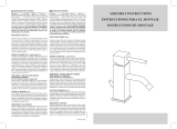
ISTRUZIONI PER L'INSTALLAZIONE
In case of working pressure higher than 75 psi (5 BAR), it
would be advisable to install a working pressure reducer.
Before starting assembly operations, bleed the pipes of hot
and cold water to prevent dirt or other impurities from
affecting the operation of the faucet.
INSTALLATION PROCEDURE (Fig.1)
Screw the threaded pin (1) and the supply tubes (2) to the
faucet body (3).
(Fig.2) If the sink has three holes use the 8” plate: position
the plate (7) on the hole of the fixture, placing the plastic
sheet (8).
Position the shank (4) and the base washer (5) making
sure that the O-ring (6) is correctly positioned.
Place the faucet in the hole of the sink,
Slip the shaped seal (9) and the flange (10) onto the threa-
ded pins (1) and fix the faucet with the stay (11). Should it
be necessary to increase the steadiness of the faucet, use
the flange (13) between the shaped seal (9) and the sink.
Last connect the supply tubes (2): the left one to the hot
ASSEMBLY INSTRUCTIONS
water supply and the right supply tube to the cold water
supply. In case use the provided nipples (12).
Open the water flow and verify the functioning of the mixer
as well as the perfect sealing of all the parts.
MAINTENANCE AND TECHNICAL SUGGESTIONS
REPLACEMENT OF THE CARTRIDGE
(shut off the main water supply) (Fig.3)
Unscrew the lever (1) and take out the handle (2), unscrew
the cap (3) and the locking nut (4), then take out the car-
tridge (6). Unscrew the lever holder (5) and mount it on the
new cartridge. To assemble proceed in reverse order,
making sure the surfaces in contact with the sealing
washers are well cleaned. Close the nut (4) in such a way
to grant the sealing and in the meantime to allow that the
handle turns smoothly.
REPLACEMENT OF THE SPOUT O-RINGS (Fig.3)
Unscrew the body screw (7) and take out the spout.
Replace the O-rings (8) and the ring (9) if necessary.
To assemble proceed in reverse order making sure that the
surfaces in contact with the sealing washers are clean.
Before screwing the body screw (7), check that the ring (9)
is in a right position to receive the screw.
CLEANING THE AERATOR (Fig.3)
It is advisable to periodically clean the aerator, in order to
avoid build-up of dirt and limestone, which in time could
gradually limit the water flow. To disassemble the aerator
(10), unscrew it and clean the filter (11) from all impurities,
reassemble by proceeding in the reverse order, making
sure the gasket (12) is correctly placed.
MAINTENANCE OF THE SURFACES
While cleaning, the surface of the faucet has to be cold
(warmth quickens the wearing out of the surface). Look out
not to use cleaning products which contain acids or corrosi-
ve substances. The faucet has to be daily wiped with a soft
cloth. Avoid corrosives, abrasive sponges or any other simi-
lar product. Soon after cleaning, wash away with cold water
the detergent residues. Damages to our products brought
about by a not appropriate treatment are unsecured.
En caso de presiones de ejercicio superiores a 5 BAR (~75
psi), se aconseja el uso de un reductor de presión. Antes de
efectuar el montaje, se aconseja vaciar las tuberías del
agua caliente y fría para evitar que suciedad y pequeñas
impurezas comprometan el funcionamiento del grifo.
INSTALACIÓN DEL GRIFO (Fig.1)
Instalar el perno roscado (1) y los tubos de alimentación
(2) en el cuerpo del grifo (3).
(Fig.2) Si el fregadero tiene tres agujeros utilizar la plan-
cha de 8”: posicionar la plancha (7) sobre el agujero del
sanitario, interponiendo la base de material plástico (8).
Introducir el caño prolongador (4) y el disco de asiento (5),
cerciorándose de posicionar el o-ring (6) correctamente.
Introducir el grifo en el agujero del fregadero, ensartar la
junta moldeada (9) y la brida (10) en el perno roscado (1)
y fijar el grifo con el tirante (11). Para aumentar la estabili-
dad del grifo, utilizar la brida (13) entre guarnición mol-
deada (9) y el fregadero. Por fin conectar los tubos de ali-
mentación (2): el tubo de alimentación izquierdo al sumini-
stro de agua caliente y el tubo de alimentación derecho al
suministro de agua fría. En caso utilizar las junturas provi-
stas (12). Abrir el suministro de agua y verificar el correc-
to funcionamiento del grifo y el cierre de todas sus partes.
MANUTENCION
Y CONSEJOS TECNICO-PRATICOS
SUSTITUCION DEL CARTUCHO
(cerrar el suministro principal de agua) (Fig.3)
Destornillar la palanca de mando (1), sacar la manilla (2),
destornillar el capuchón (3) y la virola de apriete (4), luego
sacar el cartucho (6). Destornillar el seguro manilla (5) y
enroscarlo en el nuevo cartucho. Introducir el cartucho y
montar todo procediendo en el sentido inverso, cerciorán-
dose de limpiar las superficies en contacto con las guarni-
ciones de retención. Enroscar la virola (4) para garantizar
el cierre y permitir un movimiento suave de la manilla.
SUSTITUCION DE LOS O-RINGS DEL CAÑO (Fig.3)
Destornillar el tornillo (7) y sacar el caño. Sustituir los
o-rings (8) y el anillo (9) de ser necesario.
Para el montaje, proceder en orden y sentido inverso, cer-
ciorándose de limpiar las superficies en contacto con las
guarniciones de retención.
Antes de enroscar el tornillo (7), cerciorarse que el anillo
(9) es en posición optimal para recibir el tornillo.
LIMPIEZA DEL AIREADOR (Fig. 3)
Es aconsejable efectuar la limpieza periódica del aireador
para evitar que se acumulen residuos y caliza que con el
pasar del tiempo son la causa de una gradual disminución
del caudal. Para desmontar el aireador (10), destornillarlo
y limpiar el filtro (11) quitando las impurezas, montar de
nuevo en el sentido inverso, cerciorándose de posicionar
correctamente la junta (12).
MANUTENCION DE LAS SUPERFICES
Cuando se limpia el grifo, la superficie tiene que ser fría (el
calor acelera el deterioramiento de la superficie).
Cerciorarse que los productos para la limpieza no tengan
ácidos o sustancias corrosivas. El grifo tiene que ser lim-
piado cada día con un trapo suave. No utilizar esponjas
abrasivas o semejantes. Limpiar con agua fría los residuos
de detergente. Daños a grifos como consecuencia de un
tratamiento poco apropiado, están escluidos de nuestra
garancía..
Water supply Suggested Maximum Minimum
Hot water temperature 65 C° (~150F) 80 C° (~175F) 15 C° (~60F)
Working pressure rating 3 BAR (~45PSI) 5 BAR (~75PSI) 0.5 BAR (~7PSI)
General conditions of use
Alimentación Aconsejada Máxima Minima
Temperatura agua caliente 65 C° (~150F) 80 C° (~175F) 15 C° (~60F)
Presión de ejercicio 3 BAR (~45PSI) 5 BAR (~75PSI) 0.5 BAR (~7PSI)
Condiciones generales de uso
INSTRUCCIONES PARA EL MONTAJE
557ISTUSA 5-09-2005 12:06 Pagina 4
3
In caso di pressioni di esercizio superiori a 5 bar (~75 psi),
si consiglia l'uso di un riduttore di pressione. Prima di pro-
cedere al montaggio, si consiglia di spurgare le tubature del-
l'acqua calda e fredda onde evitare che sporcizia e piccole
impurità compromettano il funzionamento del rubinetto.
INSTALLAZIONE RUBINETTO (Fig.1)
Avvitare il perno filettato (1) e i flessibili di alimentazione
(2) sul corpo rubinetto (3).
(Fig.2) Se il lavello ha tre fori utilizzare la piastra da 8”:
posizionare la piastra (7) sul foro del sanitario interponen-
do la base in materiale plastico (8).
Posizionare il distanziale (4), la rondella di base (5) aven-
do cura che l’oring (6) sia correttamente posizionato.
Posizionare il rubinetto nel foro del lavello, infilare la guar-
nizione sagomata (9) e la flangia (10) sul perno filettato (1)
e fissare il rubinetto tramite il tirante (11). Qualora si rite-
nesse necessario aumentare la stabilità del rubinetto, utiliz-
zare la flangia (13) tra guarnizione sagomata (9) e lavello.
Infine collegare i tubetti di alimentazione (2): il sinistro all’e-
rogazione dell’acqua calda ed il tubetto di alimentazione
destro all’erogazione dell’acqua fredda. Utilizzare even-
tualmente i raccordi forniti (12).
Aprire l'acqua e verificare il corretto funzionamento del
miscelatore nonché la perfetta tenuta di tutte le sue parti.
MANUTENZIONE E CONSIGLI TECNICO PRATICI
SOSTITUZIONE CARTUCCIA
(chiudere l'impianto idrico) (Fig.3)
Svitare la leva di comando (1) e togliere la maniglia (2),
svitare il cappuccio (3) e la ghiera di serraggio (4) ed
estrarre la cartuccia (6). Svitare l’inserto (5) e rimontarlo
sulla nuova cartuccia. Procedendo in senso inverso rimon-
tare la cartuccia, facendo particolare attenzione alla pulizia
delle superfici dove agiscono le guarnizioni di tenuta.
Chiudere la ghiera (4) in modo tale da garantire la tenuta
e al tempo stesso consentire un morbido movimento della
maniglia.
SOSTITUZIONE O-RINGS BOCCA (Fig.3)
Svitare la vite di fissaggio (7) ed estrarre la bocca di ero-
gazione. Sostituire gli o-rings di tenuta (8) e l'anello (9) se
necessario.
Per il montaggio, procedere in senso inverso facendo par-
ticolare attenzione alla pulizia delle superfici dove agisco-
no le guarnizioni di tenuta.
Prima di riavvitare la vite di fissaggio (7) posteriore, con-
trollare la posizione dell'anello guida (9) sul raccordo, posi-
zionato in modo tale da ricevere la vite nella spaccatura.
PULIZIA AREATORE (Fig.3)
E` buona norma procedere alla pulizia periodica dell’aera-
tore per evitare l’accumulo di detriti e calcare che con il
passare del tempo causa una graduale diminuzione della
portata. Per procedere allo smontaggio dell’aeratore svita-
re quest'ultimo (10) e pulire il filtro (11) dalle impurità come
sopra indicato, rimontare invertendo le operazioni avendo
cura di posizionare correttamente la guarnizione (12).
MANUTENZIONE DELLE SUPERFICI
Durante la pulizia, la superficie del rubinetto deve essere
fredda (il calore accelera il logorio della superficie stessa).
Accertarsi che i prodotti per la pulizia non contengano acidi
o sostanze corrosive. Il rubinetto deve essere asciugato
quotidianamente con un panno morbido. Evitare assoluta-
mente pagliette, spugne abrasive o similari. Subito dopo la
pulizia, sciacquare bene i residui di detergente con acqua
fredda. Danni ai rubinetti, conseguenti da un trattamento
non appropriato, sono esclusi dalla garanzia.
Fig. 2Fig. 1
Fig. 1
Alimentazione Raccomandata Massima Minima
Temperatura acqua calda 65 C° (~150F) 80 C° (~175F) 15 C° (~60F)
Pressione di esercizio 3 BAR (~45PSI) 5 BAR (~75PSI) 0.5 BAR (~7PSI)
Condizioni generali d’uso
21
ISTRUZIONI PER L'INSTALLAZIONE
In case of working pressure higher than 75 psi (5 BAR), it
would be advisable to install a working pressure reducer.
Before starting assembly operations, bleed the pipes of hot
and cold water to prevent dirt or other impurities from
affecting the operation of the faucet.
INSTALLATION PROCEDURE (Fig.1)
Screw the threaded pin (1) and the supply tubes (2) to the
faucet body (3).
(Fig.2) If the sink has three holes use the 8” plate: position
the plate (7) on the hole of the fixture, placing the plastic
sheet (8).
Position the shank (4) and the base washer (5) making
sure that the O-ring (6) is correctly positioned.
Place the faucet in the hole of the sink,
Slip the shaped seal (9) and the flange (10) onto the threa-
ded pins (1) and fix the faucet with the stay (11). Should it
be necessary to increase the steadiness of the faucet, use
the flange (13) between the shaped seal (9) and the sink.
Last connect the supply tubes (2): the left one to the hot
ASSEMBLY INSTRUCTIONS
water supply and the right supply tube to the cold water
supply. In case use the provided nipples (12).
Open the water flow and verify the functioning of the mixer
as well as the perfect sealing of all the parts.
MAINTENANCE AND TECHNICAL SUGGESTIONS
REPLACEMENT OF THE CARTRIDGE
(shut off the main water supply) (Fig.3)
Unscrew the lever (1) and take out the handle (2), unscrew
the cap (3) and the locking nut (4), then take out the car-
tridge (6). Unscrew the lever holder (5) and mount it on the
new cartridge. To assemble proceed in reverse order,
making sure the surfaces in contact with the sealing
washers are well cleaned. Close the nut (4) in such a way
to grant the sealing and in the meantime to allow that the
handle turns smoothly.
REPLACEMENT OF THE SPOUT O-RINGS (Fig.3)
Unscrew the body screw (7) and take out the spout.
Replace the O-rings (8) and the ring (9) if necessary.
To assemble proceed in reverse order making sure that the
surfaces in contact with the sealing washers are clean.
Before screwing the body screw (7), check that the ring (9)
is in a right position to receive the screw.
CLEANING THE AERATOR (Fig.3)
It is advisable to periodically clean the aerator, in order to
avoid build-up of dirt and limestone, which in time could
gradually limit the water flow. To disassemble the aerator
(10), unscrew it and clean the filter (11) from all impurities,
reassemble by proceeding in the reverse order, making
sure the gasket (12) is correctly placed.
MAINTENANCE OF THE SURFACES
While cleaning, the surface of the faucet has to be cold
(warmth quickens the wearing out of the surface). Look out
not to use cleaning products which contain acids or corrosi-
ve substances. The faucet has to be daily wiped with a soft
cloth. Avoid corrosives, abrasive sponges or any other simi-
lar product. Soon after cleaning, wash away with cold water
the detergent residues. Damages to our products brought
about by a not appropriate treatment are unsecured.
En caso de presiones de ejercicio superiores a 5 BAR (~75
psi), se aconseja el uso de un reductor de presión. Antes de
efectuar el montaje, se aconseja vaciar las tuberías del
agua caliente y fría para evitar que suciedad y pequeñas
impurezas comprometan el funcionamiento del grifo.
INSTALACIÓN DEL GRIFO (Fig.1)
Instalar el perno roscado (1) y los tubos de alimentación
(2) en el cuerpo del grifo (3).
(Fig.2) Si el fregadero tiene tres agujeros utilizar la plan-
cha de 8”: posicionar la plancha (7) sobre el agujero del
sanitario, interponiendo la base de material plástico (8).
Introducir el caño prolongador (4) y el disco de asiento (5),
cerciorándose de posicionar el o-ring (6) correctamente.
Introducir el grifo en el agujero del fregadero, ensartar la
junta moldeada (9) y la brida (10) en el perno roscado (1)
y fijar el grifo con el tirante (11). Para aumentar la estabili-
dad del grifo, utilizar la brida (13) entre guarnición mol-
deada (9) y el fregadero. Por fin conectar los tubos de ali-
mentación (2): el tubo de alimentación izquierdo al sumini-
stro de agua caliente y el tubo de alimentación derecho al
suministro de agua fría. En caso utilizar las junturas provi-
stas (12). Abrir el suministro de agua y verificar el correc-
to funcionamiento del grifo y el cierre de todas sus partes.
MANUTENCION
Y CONSEJOS TECNICO-PRATICOS
SUSTITUCION DEL CARTUCHO
(cerrar el suministro principal de agua) (Fig.3)
Destornillar la palanca de mando (1), sacar la manilla (2),
destornillar el capuchón (3) y la virola de apriete (4), luego
sacar el cartucho (6). Destornillar el seguro manilla (5) y
enroscarlo en el nuevo cartucho. Introducir el cartucho y
montar todo procediendo en el sentido inverso, cerciorán-
dose de limpiar las superficies en contacto con las guarni-
ciones de retención. Enroscar la virola (4) para garantizar
el cierre y permitir un movimiento suave de la manilla.
SUSTITUCION DE LOS O-RINGS DEL CAÑO (Fig.3)
Destornillar el tornillo (7) y sacar el caño. Sustituir los
o-rings (8) y el anillo (9) de ser necesario.
Para el montaje, proceder en orden y sentido inverso, cer-
ciorándose de limpiar las superficies en contacto con las
guarniciones de retención.
Antes de enroscar el tornillo (7), cerciorarse que el anillo
(9) es en posición optimal para recibir el tornillo.
LIMPIEZA DEL AIREADOR (Fig. 3)
Es aconsejable efectuar la limpieza periódica del aireador
para evitar que se acumulen residuos y caliza que con el
pasar del tiempo son la causa de una gradual disminución
del caudal. Para desmontar el aireador (10), destornillarlo
y limpiar el filtro (11) quitando las impurezas, montar de
nuevo en el sentido inverso, cerciorándose de posicionar
correctamente la junta (12).
MANUTENCION DE LAS SUPERFICES
Cuando se limpia el grifo, la superficie tiene que ser fría (el
calor acelera el deterioramiento de la superficie).
Cerciorarse que los productos para la limpieza no tengan
ácidos o sustancias corrosivas. El grifo tiene que ser lim-
piado cada día con un trapo suave. No utilizar esponjas
abrasivas o semejantes. Limpiar con agua fría los residuos
de detergente. Daños a grifos como consecuencia de un
tratamiento poco apropiado, están escluidos de nuestra
garancía..
Water supply Suggested Maximum Minimum
Hot water temperature 65 C° (~150F) 80 C° (~175F) 15 C° (~60F)
Working pressure rating 3 BAR (~45PSI) 5 BAR (~75PSI) 0.5 BAR (~7PSI)
General conditions of use
Alimentación Aconsejada Máxima Minima
Temperatura agua caliente 65 C° (~150F) 80 C° (~175F) 15 C° (~60F)
Presión de ejercicio 3 BAR (~45PSI) 5 BAR (~75PSI) 0.5 BAR (~7PSI)
Condiciones generales de uso
INSTRUCCIONES PARA EL MONTAJE
557ISTUSA 5-09-2005 12:06 Pagina 4
ASSEMBLY INSTRUCTIONS
INSTRUCCIONES PARA EL MONTAJE
Water supply
Hot water temperature
Working pressure rating
Alimentación
Temperatura agua caliente
Presión de ejercicio
Suggested
65 C° (~150F)
3 BAR (~45PSI)
Aconsejada
65 C° (~150F)
3 BAR (~45PSI)
Maximum
80 C° (~175F)
5 BAR (~75PSI)
Máxima
80 C° (~175F)
5 BAR (~75PSI)
Minimum
15 C° (~60F)
0.5 BAR (~7PSI)
Minima
15 C° (~60F)
0.5 BAR (~7PSI)
In case of working pressure higher than 75 psi (5 BAR), it
would be advisable to install a working pressure reducer.
Before starting assembly operations, bleed the pipes of hot
and cold water to prevent dirt or other impurities from af-
fecting the operation of the faucet.
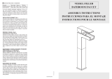
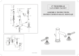
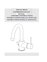
INSTALLATION PROCEDURE (Fig.1)
Screw the threaded pin (1) to the faucet body (3).
(Fig.2) If the sink has three holes use the 8” plate: position
the plate (6) on the hole of the fixture, placing the plastic
sheet (7).
Position the base ring (4) and making sure that the O-ring
(5) is correctly positioned.
Place the faucet in the hole of the sink,
slip the shaped seal (8) and the flange (9) onto the threaded
pin (1) and fix the faucet with the stay (10). Should it be
necessary to increase the steadiness of the faucet, use the
flange (11) between the shaped seal (8) and the sink.
Last connect the supply tubes (2): the left one to the hot
water supply and the right supply tube to the cold water
supply.
Open the water flow and verify the functioning of the mixer
as well as the perfect sealing of all the parts.
MAINTENANCE AND TECHNICAL SUGGESTIONS
REPLACEMENT OF THE CARTRIDGE
(shut off the main water supply) (Fig.3)
Unscrew the lever (1) and the grub screw (2), then take out
the handle, unscrew the cap (4) and the locking nut (5),
then take out the cartridge (7). Unscrew the lever holder (6)
and mount it on the new cartridge. To assemble proceed in
reverse order, making sure the surfaces in contact with the
sealing washers are well cleaned. Close the nut (5) in such
a way to grant the sealing and in the meantime to allow that
the handle turns smoothly.
REPLACEMENT OF THE SPOUT O-RINGS (Fig.3)
Unscrew the body screw (9) and take out the spout from
the faucet body (8).
En caso de presiones de ejercicio superiores a 5 BAR (~75
psi), se aconseja el uso de un reductor de presión. Antes
de efectuar el montaje, se aconseja vaciar las tuberías del
agua caliente y fría para evitar que suciedad y pequeñas
impurezas comprometan el funcionamiento del grifo.
INSTALACIÓN DEL GRIFO (Fig.1)
Instalar el perno roscado (1) en el cuerpo del grifo (3).
(Fig.2) Si el fregadero tiene tres agujeros utilizar la plancha
de 8”: posicionar la plancha (6) sobre el agujero del sanita-
rio, interponiendo la base de material plástico (7).
Introducir el disco de asiento (4) cerciorándose de posicio-
nar el o-ring (5) correctamente.
Introducir el grifo en el agujero del fregadero, ensartar la
junta moldeada (8) y la brida (9) en el perno roscado (1) y
fijar el grifo con el tirante (10). Para aumentar la estabilidad
del grifo, utilizar la brida (11) entre guarnición moldeada (8)
y el fregadero.
Por fin conectar los tubos de alimentación (2): el tubo de
alimentación izquierdo al suministro de agua caliente y el
tubo de alimentación derecho al suministro de agua fría.
Abrir el suministro de agua y verificar el correcto funciona-
miento del grifo y el cierre de todas sus partes.
MANUTENCION Y CONSEJOS TECNICO-PRATICOS
SUSTITUCION DEL CARTUCHO
(cerrar el suministro principal de agua) (Fig.3)
Destornillar la palanca de mando (1) y la clavija (2), luego
sacar la manilla (3), destornillar el capuchón (4) y la virola
de apriete (5), luego sacar el cartucho (7). Destornillar el
seguro manilla (6) y enroscarlo en el nuevo cartucho. Intro-
ducir el cartucho y montar todo procediendo en el sentido
inverso, cerciorándose de limpiar las superficies en con-
tacto con las guarniciones de retención. Enroscar la virola
(5) para garantizar el cierre y permitir un movimiento suave
de la manilla.
SUSTITUCION DE LOS O-RINGS DEL CAÑO (Fig.3)
Destornillar el tornillo (9) y sacar el caño del cuerpo del
grifo (8).
Replace the O-rings (10) and the ring (11) if necessary.
To assemble proceed in reverse order making sure that the
surfaces in contact with the sealing washers are clean.
Before screwing the body screw (9), check that the ring
(11) is in a right position to receive the screw.
REPLACEMENT OF THE NO-RETURN VALVE (Fig.3)
To replace the no-return valve in case of bad functioning,
unscrew the spray (14) from the spray hose, take out the
washer (12) and with a screwdriver take out the no-return
valve (13).
To assemble proceed in reverse order, placing the no-re-
turn valve (13) as indicated, place the washer (12) correctly
in the flexible and screw the spray (14).
CLEANING THE AERATOR (Fig.3)
It is advisable to periodically clean the aerator, in order to
avoid build-up of dirt and limestone, which in time could
gradually limit the water flow. To disassemble the aerator
(17), unscrew it and clean the filter (16) from all impurities,
reassemble by proceeding in the reverse order, making
sure the gasket (15) is correctly placed.
MAINTENANCE OF THE SURFACES
While cleaning, the surface of the faucet has to be cold
(warmth quickens the wearing out of the surface). Look
out not to use cleaning products which contain acids or
corrosive substances. The faucet has to be daily wiped
with a soft cloth. Avoid corrosives, abrasive sponges or
any other similar product. Soon after cleaning, wash away
with cold water the detergent residues. Damages to our
products brought about by a not appropriate treatment are
unsecured.
For the politics of mutual improvement, Paini SpA reser-
ves the right to make revisions in product specifications
without notice, therefore the images and data contained in
this instruction sheet have to be considered as indicative.
Sustituir los o-rings (10) y el anillo (11) de ser necesario.
Para el montaje, proceder en orden y sentido inverso, cer-
ciorándose de limpiar las superficies en contacto con las
guarniciones de retención.
Antes de enroscar el tornillo (9), cerciorarse que el anillo
(11) es en posición optimal para recibir el tornillo.
SUSTITUCION DE LA VALVULA DE FLUJO SIMPLE
(Fig.3)
Para remplazar la válvula de flujo simple, destornillar la du-
cha (14) del flexible ducha, sacar la junta (12) y medio del
destornillador sacar la válvula de flujo simple (13).
Para el montaje, proceder en orden inverso, introduciendo la
válvula de flujo simple (13) como en la figura, posicionar cor-
rectamente la junta (12) nel flexible y enroscar la ducha (14).
LIMPIEZA DEL AIREADOR (Fig. 3)
Es aconsejable efectuar la limpieza periódica del aireador
para evitar que se acumulen residuos y caliza que con el
pasar del tiempo son la causa de una gradual disminución
del caudal. Para desmontar el aireador (17), destornillarlo
y limpiar el filtro (16) quitando las impurezas, montar de
nuevo en el sentido inverso, cerciorándose de posicionar
correctamente la junta (15).
MANUTENCION DE LAS SUPERFICES
Cuando se limpia el grifo, la superficie tiene que ser fría
(el calor acelera el deterioramiento de la superficie). Cer-
ciorarse que los productos para la limpieza no tengan
ácidos o sustancias corrosivas. El grifo tiene que ser lim-
piado cada día con un trapo suave. No utilizar esponjas
abrasivas o semejantes. Limpiar con agua fría los residuos
de detergente. Daños a grifos como consecuencia de un
tratamiento poco apropiado, están escluidos de nuestra
garancía.
Por su política de continuo progreso, Paini SpA se reserva
el derecho de modificar las características de los produc-
tos de grifería sin previo aviso, por lo tanto los diseños y
los datos de estas instrucciones tienen que ser considera-
dos como indicativos.
General conditions of use General conditions of use
-
 1
1
-
 2
2


Glacier Bay 78PW557PELFHD Guía de instalación
- Categoría
- Artículos sanitarios
- Tipo
- Guía de instalación
en otros idiomas
Otros documentos
-
 LaToscana 57CR211 Guía de instalación
-
 LaToscana 84CR205LLR Guía de instalación
-
 LaToscana 78CR211LLLFEX Guía de instalación
-
 LaToscana 88CR214 Guía de instalación
-
 LaToscana 78PW250 Guía de instalación
-
Fortis 7855700BN Guía de instalación
-
-
-
-


