Sylvania 6900DTD Manual de usuario
- Categoría
- Decodificadores de TV
- Tipo
- Manual de usuario
Este manual también es adecuado para

INSTRUCCIONES EN ESPAÑOL INCLUIDAS.
ATSC/NTSC STB
6900DTD
As an ENERGY STAR
®
Partner, our company has determined
that this product meets the E
NERGY
STAR
®
guidelines for energy efficiency.
E
NERGY STAR
®
is a U.S. registered mark.
OWNER S
MANUAL
If you need additional assistance for set-up or operating
after reading owner’s manual, please call
TOLL FREE : 1
-
800
-
968-3429
Please read before using this equipment.
ST201UB.qxd 04.3.9 4:04 PM Page 1

Table of Contents
1 Before Using . . . . . . . . . . . . . . . . . 3
Important Safeguards. . . . . . . . . . . . . . . 3
Precautions . . . . . . . . . . . . . . . . . . . . . . 5
Information on digital broadcasting . . . . 6
Major features of STB . . . . . . . . . . . . . . 7
Location of controls. . . . . . . . . . . . . . . . 8
Accessories . . . . . . . . . . . . . . . . . . . . . . 11
Installing batteries . . . . . . . . . . . . . . . . . 11
Reference to SETUP menu . . . . . . . . . . 12
2 Connections. . . . . . . . . . . . . . . . . . 16
Connections to antenna . . . . . . . . . . . . . 16
Connections to other devices . . . . . . . . . 18
3Initial Setups (Setup Wizard) . . . . . 25
Initial setup . . . . . . . . . . . . . . . . . . . . . . 25
4Basic Operation . . . . . . . . . . . . . . . 30
Watching TV . . . . . . . . . . . . . . . . . . . . . 30
Channel banner . . . . . . . . . . . . . . . . . . . 33
Choosing audio and language . . . . . . . . 35
Picture Still . . . . . . . . . . . . . . . . . . . . . . 37
On screen messages. . . . . . . . . . . . . . . . 38
5Advanced Operation . . . . . . . . . . . 39
Electronic Program Guide (EPG). . . . . . 39
Setup menu for preference. . . . . . . . . . . 42
CHANNEL
Adding channels . . . . . . . . . . . . . . . . . . 43
Deleting channels . . . . . . . . . . . . . . . . . 46
Adjusting antenna . . . . . . . . . . . . . . . . . 49
Receiving channels . . . . . . . . . . . . . . . . 51
DISPLAY
Selecting screen formats
(Screen ratio and Display mode) . . . . . . 54
CLOCK
Setting the clock . . . . . . . . . . . . . . . . . . 59
DETAIL
Setting a new password . . . . . . . . . . . . . 66
Setting for V-CHIP/CC . . . . . . . . . . . . . 69
Setting MPAA rating . . . . . . . . . . . . . . . 73
Setting TV rating. . . . . . . . . . . . . . . . . . 77
Selecting CC options . . . . . . . . . . . . . . . 81
Choosing the screen language . . . . . . . . 84
6 Appendix . . . . . . . . . . . . . . . . . . . . 86
Troubleshooting. . . . . . . . . . . . . . . . . . . 86
Specifications . . . . . . . . . . . . . . . . . . . . 88
Glossary and acronyms . . . . . . . . . . . . . 88
Indice
7 Guía para rápida consulta
(Español) . . . . . . . . . . . . . . . . . . . . 90
Ubicación de los controles. . . . . . . . . . . 90
Instalación de las pilas. . . . . . . . . . . . . . 91
Conexiones de antena . . . . . . . . . . . . . . 92
Conexión del STB a un SDTV
utilizando la salida VIDEO . . . . . . . . . . 93
Configuración inicial . . . . . . . . . . . . . . . 94
Warranty . . . . . . . . . . . . . . . . . . . . .
Back Cover
ST201UB.qxd 04.3.9 4:04 PM Page 2

3
EN
1A23
1 Before Using
1.Read instructions-All the safety and operating instructions
should be read before the appliance is operated.
2.Retain Instructions-The safety and operating instructions
should be retained for future reference.
3.Heed Warnings-All warnings on the appliance and in the
operating instructions should be adhered to.
4.Follow Instructions-All operating and use instructions
should be followed.
5.Cleaning-Unplug this product from the wall outlet before
cleaning. Do not use liquid cleaners or aerosol cleaners. Use
a damp cloth for cleaning.
EXCEPTION: A product that is meant for uninterrupted
service and, that for some specific reason, such as the possi-
bility of the loss of an authorization code for a CATV con-
verter, is not intended to be unplugged by the user for clean-
ing or any other purpose, may exclude the reference to
unplugging the appliance in the cleaning description other-
wise required in item 5.
6.Attachments-Do not use attachments not recommended by
this product manufacturer as they may cause hazards.
7.Water and Moisture-Do not use this product near water-for
example, near a bath tub, wash bowl, kitchen sink, or laun-
dry tub, in a wet basement, or near a swimming pool, and
the like.
8.Accessories-Do not place this product on an unstable cart,
stand, tripod, bracket, or table. This product may fall, caus-
ing serious injury to someone, and serious damage to the
appliance. Use only with a cart, stand, tripod, bracket, or
table recommended by the manufacturer, or sold with this
product. Any mounting of the appli-
ance should follow the manufactur-
er’s instructions and should use a
mounting accessory recommended
by the manufacturer. An appliance
and cart combination should be
moved with care.
Quick stops, excessive force, and
uneven surfaces may cause the
appliance and cart combination to
overturn.
AMEUBLES- Cet appareil ne doit être
placé que sur un meuble (avec ou sans
roulettes) recommandé par le fabricant.
Si vous l’installez sur un meuble à
roulettes, déplacez les deux ensembles
avec précaution. Un arrêt brusque, l’util-
isation d’une force excessive et des surfaces irrégulières
risquent de déstabiliser l’ensemble et de le renverser.
9. Ventilation-Slots and openings in the cabinet and the back
or bottom are provided for ventilation and to ensure reliable
operation of this product and to protect it from overheating,
and these openings must not be blocked or covered. The
openings should never be blocked by placing this product
on a bed, sofa, rug, or other similar surface. This product
should never be placed near or over a radiator or heat regis-
ter. This product should not be placed in a built-in installa-
tion such as a bookcase or rack unless proper ventilation is
provided or the manufacturer’s instructions have been
adhered to.
10.Power Sources-This product should be operated only from
the type of power source indicated on the marking label. If
you are not sure of the type of power supply to your home,
consult your appliance dealer or local power company. For
this products intended to operate from battery power, or
other sources, refer to the operating instructions.
11.Grounding or Polarization-This product is equipped with
a polarized alternating-current line plug(a plug having one
blade wider than the other). This plug will fit into the
power outlet only one way. This is a safety feature. If you
are unable to insert the plug fully into the outlet, try revers-
ing the plug. If the plug should still fail to fit, contact your
electrician to replace your obsolete outlet. Do not defeat
the safety purpose of the polarized plug.
12.Power-Cord Protection-Power-supply cords should be
routed so that they are not likely to be walked on or
pinched by items placed upon or against them, paying par-
ticular attention to cords at plugs, convenience receptacles,
and the point where they exit from the appliance.
WARNING: TO REDUCE THE RISK OF FIRE OR ELECTRIC SHOCK, DO NOT EXPOSE THIS APPLIANCE
TO RAIN OR MOISTURE.
CAUTION: TO REDUCE THE RISK OF ELECTRIC
SHOCK, DO NOT REMOVE COVER (OR BACK).
NO USER SERVICEABLE PARTS INSIDE. REFER
SERVICING TO QUALIFIED SERVICE PERSON-
NEL.
CAUTION
RISK OF ELECTRIC SHOCK
DO NOT OPEN
THIS SYMBOL INDICATES THAT DAN-
GEROUS VOLTAGE CONSTITUTING A
RISK OF ELECTRIC SHOCK IS PRESENT
WITHIN THIS UNIT.
THIS SYMBOL INDICATES THAT THERE
ARE IMPORTANT OPERATING AND
MAINTENANCE INSTRUCTIONS IN THE
LITERATURE ACCOMPANYING THE
APPLIANCE.
The caution marking is located on the rear of the cabinet.
IMPORTANT SAFEGUARDS
ST201UB.qxd 04.3.9 4:04 PM Page 3

4
EN
1A23
13.Outdoor Antenna grounding-If an outside antenna or
cable system is connected to this product, be sure the
antenna or cable system is grounded so as to provide some
protection against voltage surges and built-up static
charges. Article 810 of the National Electrical Code,
ANSI/NFPA No. 70, provides information with respect to
proper grounding of the mast and supporting structure,
grounding of the lead-in wire to an antenna discharge unit,
size of grounding conductors, location of antenna-discharge
unit, connection to grounding electrodes, and requirements
for the grounding electrode. (Fig. A)
14.Lightning-For added protection for this product receiver
during a lightning storm, or when it is left unattended and
unused for long periods of time, unplug it from the wall
outlet and disconnect the antenna or cable system. This will
prevent damage to this product due to lightning and power-
line surges.
15.Power Lines-An outside antenna system should not be
located in the vicinity of overhead power lines or other
electric light or power circuits, or where it can fall into
such power lines or circuits. When installing an outside
antenna system, extreme care should be taken to keep from
touching such power lines or circuits as contact with them
might be fatal.
16.Overloading-Do not overload wall outlets and extension
cords as this can result in a risk of fire or electric shock.
17.Object and Liquid Entry-Never push objects of any kind
into this product through openings as they may touch dan-
gerous voltage points or short out parts that could result in
a fire or electric shock. Never spill liquid of any kind on
this product.
18.Servicing-Do not attempt to service this product yourself
as opening or removing covers may expose you to danger-
ous voltage or other hazards. Refer all servicing to quali-
fied service personnel.
19.Damage Requiring Service-Unplug this product from the
wall outlet and refer servicing to qualified service person-
nel under the following conditions:
a. When the power-supply cord or plug is damaged or frayed.
b. If liquid has been spilled, or objects have fallen into this
product.
c. If this product has been exposed to rain or water.
d. If this product does not operate normally by following the
operating instructions. Adjust only those controls that are
covered by the operating instructions, as improper adjust-
ment of other controls may result in damage and will often
require extensive work by a qualified technician to restore
this product to its normal operation.
e. If this product has been dropped or damaged in any way.
f. When this product exhibits a distinct change in perfor-
mance-this indicates a need for service.
20.Replacement Parts-When replacement parts are required,
be sure the service technician has used replacement parts
specified by the manufacturer that have the same character-
istics as the original part. Unauthorized substitutions may
result in fire, electric shock, injury to persons or other haz-
ards.
21.Safety Check-Upon completion of any service or repairs to
this product, ask the service technician to perform routine
safety checks to determine that this product is in proper
operating condition.
22.Heat-This product should be situated away from heat
sources such as radiators, heat registers, stoves, or other
products (including amplifiers) that produce heat.
GROUND CLAMPS
NEC - NATIONAL ELECTRICAL CODE
EXAMPLE OF ANTENNA GROUNDING AS PER
NATIONAL ELECTRICAL CODE
S2898A
WIRE
DISCHARGE UNIT
(NEC SECTION 810-20)
GROUNDING CONDUCTORS
(NEC SECTION 810-21)
ELECTRODE SYSTEM
(NEC ART 250, PART H)
SERVICE
EQUIPMENT
CLAMP
ANTENNA
LEAD IN
ANTENNA
POWER SERVICE GROUNDING
GROUND
ELECTRIC
FIGURE A
CAUTION: TO PREVENT ELECTRIC SHOCK, MATCH WIDE BLADE OF PLUG TO WIDE SLOT, FULLY
INSERT.
ATTENTION: POUR ÉVITER LES CHOC ÉLECTRIQUES, INTRODUIRE LA LAME LA PLUS LARGE DE
LA FICHE DANS LA BORNE CORRESPONDANTE DE LA PRISE ET POUSSER JUSQU’AU FOND.
ST201UB.qxd 04.3.9 4:04 PM Page 4

5
EN
1A23
1 Before Using
AV OID THE HAZARDS OF
ELECTRICAL SHOCK AND FIRE
This equipment has been tested and found to com-
ply with the limits for a Class B digital device, pur-
suant to Part 15 of the FCC Rules. These limits are
designed to provide reasonable protection against
harmful interference in a residential installation.
This equipment generates, uses, and can radiate
radio frequency energy and, if not installed and
used in accordance with the instructions, may cause
harmful interference to radio communications.
However, there is no guarantee that interference
will not occur in a particular installation. If this
equipment does cause harmful interference to
radio or television reception, which can be deter-
mined by turning the equipment off and on, the
user is encouraged to try to correct the interfer-
ence by one or more of the following measures:
1) Reorient or relocate the receiving antenna.
2) Increase the separation between the equipment
and receiver.
3) Connect the equipment into an outlet on a cir-
cuit different from that to which the receiver is
connected.
4) Consult the dealer or an experienced radio/TV
technician for help.
PRECAUTIONSPRECAUTIONS
LOCATION
For safe operation and satisfactory performance of
your this product, keep the following in mind when
selecting a place for its installation:
•
Shield it from direct sunlight and keep it away
from sources of intense heat.
•
Avoid dusty or humid places.
•
Avoid places with insufficient ventilation for proper
heat dissipation. Do not block the ventilation holes
at the top and bottom of the unit. Do not place the
unit on a carpet because this will block the ventila-
tion holes.
•
Install unit in a horizontal position.
•
Avoid locations subject to strong vibration.
•
Do not place this product near strong magnetic fields.
•
Avoid moving this product to locations where tem-
perature differences are extreme.
•
Do not handle the power cord with wet hands.
•
Do not pull on the power cord when disconnecting
it from an AC wall outlet. Grasp it by the plug.
•
If, by accident, water is spilled on your unit, unplug
the power cord immediately and take the unit to our
Authorized Service Center for servicing.
•
Do not put your fingers or objects into this product
cassette holder.
•
Do not place anything directly on top of the unit.
IMPORTANT COPYRIGHT INFORMATION
Unauthorized recording or use of broadcast televi-
sion programming, video tape, film or other copy-
righted material may violate applicable copyright
laws. We assume no responsibility for the unautho-
rized duplication, use, or other acts which infringe
upon the rights of copyright owners.
FCC WARNING- This equipment may gener-
ate or use radio frequency energy. Changes or
modifications to this equipment may cause
harmful interference unless the modifications
are expressly approved in the instruction man-
ual. The user could lose the authority to oper-
ate this equipment if an unauthorized change
or modification is made.
The serial number of this product may be found on the back of the unit. No others has the same serial number
as yours. You should record the number and other vital information here and retain this book as a permanent
record of your purchase to aid identification in case of theft. Serial numbers are not kept on file.
Date of Purchase
Dealer Purchase from
Dealer Address
Dealer Phone No.
Model No.
Serial No.
ST201UB.qxd 04.3.9 4:04 PM Page 5

6
EN
1A23
Before Using
Digital broadcasting is the most advanced format of broadcasting, employing a new technology for
compression of audio and video signals which allows broadcasters to transmit digital signals using existing
terrestrial systems.
Due to this dramatic progress, new features of broadcasting service such as widescreen formats and higher
definition can provide a way to experience the full benefits of digital transmission.
High Definition Television (HDTV*) broadcasts can provide pictures twice as sharp as a conventional
broadcast and features sound encoded with Dolby® digital* 5.1 surround sound. When connected to a
receiver (sold separately) that features Dolby® digital decoding will provide a true theater experience in the
home.
Digital broadcasting has overcome problems experienced with analog television such as ghosting, "snowy"
pictures and interference. Digital television has a dramatic effect on these problems by its very nature.
In addition, the number of channels available has dramatically increased, so that you can make the best choice
among the variety of programs anytime with a clear picture.
The benefits extend not only to HDTV. It will also be possible to transmit multiple Standard Definition
Television (SDTV*) programs within the same bandwidth. Some data capacity could also be allocated to
provide more effective closed captioning or multiple language soundtracks.
Your current TV should be used for its entire service life.
STB will make this possible.
NTSC
Analog/digital
terrestrial antenna
Analog/digital
terrestrial signals
ATSC
STB
Receives both
ATSC and NTSC
TV
Information on digital broadcasting
ST201UB.qxd 04.3.9 4:04 PM Page 6

7
EN
1A23
Before Using
1 Before Using
• Capable of receiving digital (ATSC*), analog (NTSC*), and cable (NTSC) broadcasts
• Capable of receiving High Definition TV broadcasts
• Capable of receiving Dolby® digital 5.1 audio
• Alternate languages for OSD are available.
(English, Spanish, French)
• Component video output jacks (Y/ Pb/ Pr)
• Sub-channels* are available through a single digital channel.
Major features of STB
HDTV:
High Definition Television:
HDTV signal formats are 1080i (interlaced scan) and
720p (progressive scan). HDTV provides the highest
resolution picture and audio in either stereo or 5.1
channel surround sound.
Dolby® Digital:
Dolby® Digital (when available) provides 6
independent soundtrack channels through the coaxial
output jack.
STB has a Dolby Digital output (labeled DIGITAL
AUDIO (COAXIAL)) that can be connected to an
external Digital Audio receiver/ decoder equipped
with a coaxial input. With additional equipment you
can enjoy more dynamic and realistic sound at home.
SDTV:
Standard Definition Television:
SDTV signal formats are 480p and 480i. SDTV
provides lower resolution, yet presents a very sharp,
clear picture. Lower resolution allows broadcasters to
transmit multiple programs per channel.
ATSC:
ATSC (Advanced Television Systems Committee) is
the group that has been working to establish the
standards for digital television broadcasting and
digital television equipment - including both SDTV
and HDTV.
NTSC:
NTSC (National Television Standards Committee)
refers to the group that first established the standards
used for conventional analog television broadcasting
and TV equipment.
Sub-Channel:
Because of the compression of audio and video
signals, each digital channel is able to carry different
programs on sub-channels through a single channel.
You can select them by simply pressing CH
o / p
buttons on your remote control when available.
ST201UB.qxd 04.3.9 4:04 PM Page 7

8
EN
1A23
Before Using
1POWER button:
Turns STB on and off.
2POWER indicator:
Lights up while STB is on.
NOTE:
When turning the STB on, the power indicator will blink first and light up.
When turning the STB off, the power indicator will blink first and go off.
3Remote control sensor:
Receives signals from your remote control and enables you to control STB from a distance.
4Navigation buttons
o / p / s / B:
Press to move the selected item or menu up, down, left or right.
5 SETUP button:
Press to enter or exit SETUP menu.
6 ENTER button:
In SETUP menu, press to determine your selection.
7 CHANNEL
o / p buttons:
Press to change the channels up or down.
12 3 4 567
FRONT PANEL
Location of controls
ST201UB.qxd 04.3.9 4:04 PM Page 8

9
EN
1A23
Before Using
1 Before Using
1 ANT. IN Jack:
Use to connect an antenna to STB.
2 DIGITAL AUDIO (COAXIAL) Jack:
Use to connect a decoder or an amplifier to STB with a digital coaxial cable.
NOTE:
You must use this jack and a Dolby® Digital receiver for Dolby® Digital 5.1 playback.
3AUDIO R/ L Jacks: (2 pairs)
Use to connect your TV, a stereo system or a VCR to STB with standard audio cables.
NOTE for audio output:
There will be both digital audio output and analog audio output during digital broadcast. There will be
only analog audio output during analog broadcast. When you want digital audio output during digital
broadcast, the digital audio (coaxial) jack must be used.
Refer to the page describing the connection to a decoder with Dolby® Digital.
4 VIDEO Jack: (Composite)
Use to connect your TV or a VCR to STB with a standard video cable.
5 S-VIDEO Jack:
Use to connect your TV to STB with an S-Video cable.
NOTE:
When you use an S-Video cable, a composite video cable (yellow) is not necessary.
6 COMPONENT VIDEO Jacks (Y/ Pb/ Pr):
Use to connect your TV to STB with component video cables.
NOTE:
This connection is required to display a high definition broadcast.
Y (green), Pb (blue), Pr (red)
7 Resolution selection switch (1080i/ 480p/ 480i):
Use to select the STB video output resolution 1080i, 480p and 480i. The default setting is 480i.
8AC power cord:
Connect to AC outlet.
135
REAR PANEL
42 8 76
ST201UB.qxd 04.3.9 4:04 PM Page 9

1POWER button:
Turns STB on and off.
2 Number buttons:
Use to input channel numbers and passwords, and
to set time.
3 ENTER button:
In SETUP menu, press to determine your
selection.
4 CH
o / p buttons:
Press to change the channels up or down.
5Navigation buttons
o / p / s / B:
Press to move the highlight up, down, left or
right.
The video pauses by pressing STILL o button
while you can listen to the program audio.
6 SETUP button:
Press to enter or quit SETUP menu.
7AUDIO button:
Use to select an alternate audio track while
watching a TV program.
8 PREVIOUS button:
Use to go back to the previous screen in SETUP
menu or to exit.
9 INFO button:
Use to display further information on the channel
banner or to exit.
10 EPG button:
Use to display EPG (Electronic Program Guide)
or to exit.
11 CH RETURN button:
Use to return to the channel you were last
watching.
1
6
REMOTE CONTROL
7
9
11
10
8
2
3
5
4
10
EN
1A23
Before Using
ST201UB.qxd 04.3.9 4:04 PM Page 10

You will find STB and the following accessories
when unpacking the carton box of STB:
1 Unsnap the battery cover from the back
of the remote control.
2Install two AA batteries making sure
the polarity (+ / -) direction is correct.
NOTE:
When replacing batteries, make sure to replace them
in pairs.
3 Snap the battery cover back.
CAUTION:
•
Do not mix battery types.
(alkaline and manganese)
• Do not recharge, short-circuit, heat, burn or
disassemble batteries.
Installing batteries
STB
6900DTD
Remote controller unit and AA batteries (x2)
(PART No.: NE120UD)
Owners manual (PART No.: 0EMN02308)
Accessories
11
EN
1A23
Before Using
1 Before Using
A NOTE ABOUT RECYCLING
This product’s packaging materials are recyclable and can be reused. Please dispose of any materials in
accordance with your local recycling regulations.
Batteries should never be thrown away or incinerated but disposed of in accordance with your local regula-
tions concerning chemical wastes.
ST201UB.qxd 04.3.9 4:04 PM Page 11

12
EN
1A23
Before Using
SETUP WIZARD guides you
through initial setup.
"Create new setup"
"Keep old setup"
"SETUP"
"QUIT"
QUIT SETUP
:
:
SETUP WIZARD
Language for screen (1/8)
( Refer to page 25 through page 29. )
Setting the clock (Manual)
(5/8)
( Refer to page 27. )
Channel scanning (2/8) Setting the clock (Auto)
(6/8)
Daylight savings time
(DST) (3/8)
Screen ratio (7/8)
Time zone (4/8) Display mode (8/8)
( Refer to page 25. )
( Refer to page 26. )
( Refer to page 29. )
( Refer to page 26. ) ( Refer to page 29. )
SETUP WIZARD 1/8
SETUP WIZARD 2/8
Now the system is scanning for channels.
SKIP
Digital
34%
Analog
SETUP WIZARD 3/8
Do you observe daylight saving time
(DST)?
OFF
ON
SETUP WIZARD 4/8
Select your time zone.
CENTRAL
SETUP WIZARD 5/8
Enter current time.
2001YEAR
--
DATE
-- ---
-- -- --
TIME
SET
SETUP WIZARD 6/8
Select a channel for auto clock setting.
2
Searching.
SETUP WIZARD 7/8
Select screen ratio.
SETUP WIZARD 8/8
SETUP WIZARD
( Refer to page 28. )
( Refer to page 26.)
4:3
16:9
Select display mode.
LETTERBOX
ZOOM
FULL
4
3
2
1
OFF
Reference to SETUP menu
ST201UB.qxd 04.3.9 4:04 PM Page 12

13
EN
1A23
Before Using
1 Before Using
Adding channels /
Deleting channels
( Refer to page 43, 46, 49, 51.) ( Refer to page 54, 56.)
Adjusting antenna
Receiving channels (Autoscan)
Selecting screen formats
(Screen ratio)
Selecting screen formats
(Display mode)
CHANNEL
QUIT
CHANNEL
DISPLAY
CLOCK
DETAIL
ADD/DELETE
ANTENNA
AUTOSCAN
ADD/DELETE
QUIT
CHANNEL
DISPLAY
CLOCK
DETAIL
13-0
ADD
DELETE
55
23
22
13
ANTENNA
QUIT
CHANNEL
DISPLAY
CLOCK
DETAIL
26-1
WEAK STRONG
PREVIOUS
NOW
75
PEAK
75
AUTOSCAN
QUIT
CHANNEL
DISPLAY
CLOCK
DETAIL
NEXT
PREVIOUS
AutoScan will rescan all channels.
This may take a while to complete.
DISPLAY
QUIT
CHANNEL
DISPLAY
CLOCK
DETAIL
SCREEN RATIO
4:3
DISPLAY MODE
LETTERBOX
DISPLAY
QUIT
CHANNEL
DISPLAY
CLOCK
DETAIL
SCREEN
DISPLAY
Select screen ratio.
16:9
4:3
DISPLAY
QUIT
CHANNEL
DISPLAY
CLOCK
DETAIL
SCREEN
DISPLAY
CHANNEL DISPLAY
( Refer to page 43, 46. ) ( Refer to page 54. )
( Refer to page 56. )( Refer to page 49. )
( Refer to page 51. )
Select display mode.
LETTERBOX
ZOOM
FULL
ST201UB.qxd 04.3.9 4:04 PM Page 13

14
EN
1A23
Before Using
Setting the clock (Daylight Savings Time)
Setting the clock (Time Zone)
Setting the clock (Manual)
Adjusting the clock automatically
CLOCK
QUIT
CHANNEL
DISPLAY
CLOCK
DETAIL
DST
ON
TIME ZONE
CENTRAL
MANUAL
AUTO
OFF
2002/ 1/31( THU ) 2 50PM
CLOCK
QUIT
CHANNEL
DISPLAY
CLOCK
DETAIL
Do you observe daylight saving time
(DST)?
OFF
ON
CLOCK
QUIT
CHANNEL
DISPLAY
CLOCK
DETAIL
Select your time zone.
CENTRAL
CLOCK
QUIT
CHANNEL
DISPLAY
CLOCK
DETAIL
Enter current time.
TIME 50 PM2
DATE 311 THU
YEAR 2002
SET
CLOCK
QUIT
CHANNEL
DISPLAY
CLOCK
DETAIL
Select a channel for auto clock setting.
2
Searching.
CLOCK
( Refer to page 59, 60, 62, 64. )
( Refer to page 60. )
( Refer to page 60. )
( Refer to page 62. )
( Refer to page 64. )
4
3
2
1
OFF
ST201UB.qxd 04.3.9 4:04 PM Page 14

15
EN
1A23
Before Using
1 Before Using
Setting for V-CHIP/CC
Setting MPAA rating
Setting TV rating
Setting CC options
Setting a new password
DETAIL
QUIT
CHANNEL
DISPLAY
CLOCK
DETAIL
V-CHIP / CC
MENU LANGUAGE ENGLISH
V-CHIP / CC
QUIT
CHANNEL
DISPLAY
CLOCK
DETAIL
Enter password.
Confirm password.
V-CHIP / CC
QUIT
CHANNEL
DISPLAY
CLOCK
DETAIL
V-CHIP / CC
MPAA RATING
TV RATING
CC SELECTION
NEW PASSWORD
OFF
CC1
Select CC.
CC2
CC3
CC4
TEXT1
TEXT2
TEXT3
TEXT4
V-CHIP / CC
QUIT
CHANNEL
DISPLAY
CLOCK
DETAIL
Set TV rating
TV-MA
TV-14
TV-PG
TV-G
TV-Y7
TV-Y
FV V S L D
V-CHIP / CC
QUIT
CHANNEL
DISPLAY
CLOCK
DETAIL
Set MPAA rating
X
NC-17
R
PG-13
PG
G
NR
DETAIL
Setting for V-CHIP/CC
V-CHIP / CC
QUIT
CHANNEL
DISPLAY
CLOCK
DETAIL
V-CHIP / CC
STB
MPAA RATING
TV RATING
CC SELECTION OFF
NEW PASSWORD
( Refer to page 69. ) ( Refer to page 71. )
( Refer to page 73. )
( Refer to page 77. )
( Refer to page 81. )
( Refer to page 66. )
( Refer to page 66, 69, 70, 71, 73, 77, 81, 84. )
V-CHIP / CC
QUIT
CHANNEL
DISPLAY
CLOCK
DETAIL
STB
Choose either STB or TV for
V-CHIP/CC setting.
If you choose "TV",
V-CHIP/CC functions are
processed in TV, not in STB.
TV
Choosing the screen language
DETAIL
QUIT
CHANNEL
DISPLAY
CLOCK
DETAIL
V-CHIP / CC
MENU LANGUAGE
Select menu language.
( Refer to page 84. )
V-CHIP/CC password
window
( Refer to page 70. )
V-CHIP / CC
QUIT
CHANNEL
DISPLAY
CLOCK
DETAIL
Enter password.
ST201UB.qxd 04.3.9 4:04 PM Page 15

16
EN
1A23
Connections
Use a standard antenna cable to connect the wall jack to the ANT IN Jack on STB.
STB connection to the antenna
Rear panel of STB
To the antenna
To the antenna
WHEN CONNECTING TO CABLE BOX ALSO:
NOTE:
Antenna and antenna cable are not included.
ANT. IN
Incoming cable
signals
NOTE:
Antenna, antenna cable and Cable box are not included.
STB
CABLE BOX
TV
ANT-IN
Jack
Refer to following
pages for the
connection to TV.
ANT
IN
ANT
OUT
Antenna cable
Connections to antenna
1 Use a standard antenna cable to connect the wall jack to the
ANT IN Jack on STB.
NOTE:
Refer to the following pages for the connection to TV.
2 Use an incoming cable to connect to an antenna input jack on
the cable box.
3 Use a standard antenna cable to connect an antenna output jack
on the cable box to an antenna input jack on the TV.
4 After completing the connection to TV, plug the AC power
cord of the TV into the AC outlet, then turn the TV on.
5 Select the output channel from the cable box e.g., ch3 or ch 4.
NOTE:
Refer to the TV owner’s manual for further information.
6 Plug the AC power cord of STB into the AC outlet, then turn
STB on.
Note to the Cable TV System
Installer :
This reminder is provided to call
the Cable TV system installer’s
attention to Article 820-40 of the
National Electrical Code, which
provides guidelines for proper
grounding - in particular,
specifying that the cable ground
shall be connected to the grounding
system of the building, as close to
the point of cable entry as possible.
ST201UB.qxd 04.3.9 4:04 PM Page 16

17
EN
1A23
Connections
e.g.: Connection to VCR
When you connect the antenna cable to another device, be sure to use a splitter as shown below.
CAUTION
Right
Splitter
ANT. IN
ANT. IN
RF-IN
RF-OUT
e.g.: Connection to VCR
STB
Wrong
RF-IN
RF-OUT
Antenna cable
Antenna
cables
Antenna
cables
NOTE:
Antenna, antenna cable and Splitter are not included.
STB
2 Connections
ST201UB.qxd 04.3.9 4:04 PM Page 17

18
EN
1A23
Connections
There will be various ways of connecting STB to other devices. Make your connection according to your
choice of devices, screen format, and sound format.
You will find some sample connections in the following pages.
• All jacks on STB will not need to be connected.
• When you change the connections, all devices should be turned off.
• Refer to each owner’s manual for further information on other devices.
STB connection using COMPONENT video output to TV
e.g.: Connection to HDTV
Rear panel of STB
Audio cable
Component
video cable
To audio input jacks (L, R)
To component video input jacks (Y/ Pb/ Pr)
Position of Resolution Selection Switch
If your TV is capable of displaying 1080i,
then select 1080i as shown.
If your TV is capable of displaying 480p,
then select 480p as shown.
If your TV is capable of displaying 480i,
then select 480i as shown.
1080i
480p
480i
TV Format
NOTE:
Component video cable and audio cable are not included.
Resolution Selection Switch (1080i, 480p, 480i)
Refer to the TV owner s manual for the video resolution of your TV.
Connections to other devices
ST201UB.qxd 04.3.9 4:04 PM Page 18

19
EN
1A23
Connections
1 Use a standard antenna cable to connect the wall jack to the ANT IN jack on STB.
2 Use a standard audio cable to connect the audio output jacks (L, R) of STB to the audio input jacks (L, R) on
the TV.
NOTE:
If your TV is monaural (MONO) and has only one audio jack, use a standard audio cable (white) to
connect the audio output jack (white) on STB to the audio input jack (white) on the TV. The red cable and
jack will not be used.
3 Use a component video cable to connect the component video output jacks (Y/ Pb/ Pr) on STB to the
component video input jacks (Y/ Pb/ Pr) on the TV.
4 Set the video resolution selection switch to “1080i.”
NOTE:
For the capability of your TV and further information, refer to TV owner’s manual.
5 After completing the connection to the TV, plug the AC power cord of the TV into the AC outlet, then turn
the TV on.
6 Set the TV to the input mode.
NOTE:
Refer to the TV owner’s manual for further information.
7 Plug the AC power cord of STB into the AC outlet, then turn STB on.
2 Connections
ST201UB.qxd 04.3.9 4:04 PM Page 19

20
EN
1A23
Connections
1 Use a standard antenna cable to connect the wall jack to the ANT IN jack on STB.
2 Use a standard audio cable to connect the audio output jacks (L, R) of STB to the audio input jacks (L, R) on
the TV.
3 Use an S-video cable to connect the S-VIDEO output jack on STB to an S-video input jack on the TV.
4 Set the resolution selection switch to “480i.”
5 After completing the connection to the TV, plug the AC power cord of the TV into the AC outlet, then turn
the TV on.
6 Set the TV to the input mode.
NOTE:
Refer to the TV owner’s manual for further information.
7 Plug the AC power cord of STB into the AC outlet, then turn STB on.
NOTE:
When using an S-video cable to connect, the resolution of the video signal output will always be 480i.
STB connection using S-VIDEO output to SDTV
Rear panel of STB
Audio cable
To audio input jacks (L, R)
To S-video input jack
S-video cable
NOTE:
S-video cable and audio cable are not included.
ST201UB.qxd 04.3.9 4:04 PM Page 20

21
EN
1A23
Connections
1 Use a standard antenna cable to connect the wall jack to the ANT. IN jack on STB.
2 Use a standard audio cable to connect the audio output jacks (L, R) of STB to the audio input jacks (L, R) on
the TV.
NOTE:
If your TV is monaural (MONO) and has only one audio jack, connect a standard audio cable (white) from
the audio output jack (white) on STB to an audio input jack (white) on the TV. The red cable and jack will
not be used.
3 Use a standard video cable to connect the video output jack on STB to a video input jack on the TV.
4 Set the resolution selection switch to “480i.”
5 After completing the connection to the TV, plug the AC power cord of the TV into the AC outlet, then turn
the TV on.
6 Set the TV to the input mode.
NOTE:
Refer to the TV owner’s manual for further information.
7 Plug the AC power cord of STB into the AC outlet, then turn STB on.
NOTE:
When using a standard video cable to connect, the resolution of the video signal output will always be 480i.
Rear panel of STB
Audio cable Video cable
To audio input jacks (L, R)
To a video input jacks
NOTE:
Audio cable and video cable are not included.
STB connection using VIDEO output to SDTV
2 Connections
ST201UB.qxd 04.3.9 4:04 PM Page 21

22
EN
1A23
Connections
1 Use a standard antenna cable to connect the wall jack to the ANT. IN jack on STB.
2 Use a standard audio cable to connect the audio output jacks (L, R) on STB to the audio input jacks (L, R)
on the stereo.
3 Connect STB and the TV with a video cable.
NOTE:
Refer to the pages describing the connection to TV.
4 Set the video resolution selection switch to “1080i.”
NOTE:
For the capability of your TV and further information, refer to TV owner’s manual.
5 Plug the AC power cord of the stereo into the AC outlet, then turn the stereo on.
6 Set the stereo to the input mode to which you connected the audio from the STB.
NOTE:
Refer to the stereo owner's manual for further information.
7 Plug the AC power cord of STB into the AC outlet, then turn STB on.
STB connection to a standard stereo system
STEREO COMPONENT
Rear panel of STB
Audio cable
To audio input jacks
(L, R)
To component video input
jacks (Y/ Pb/ Pr)
Component video cable
NOTE:
Component video cable and audio cable are not included.
ST201UB.qxd 04.3.9 4:04 PM Page 22

23
EN
1A23
Connections
1 Use a standard antenna cable to connect the wall jack to the ANT. IN jack on STB.
2 Connect a coaxial digital audio cable (purchase locally) from DIGITAL AUDIO (COAXIAL) output jack
on STB to a coaxial digital audio input jack on the digital decoder.
3 Connect STB and the TV with a video cable.
NOTE:
Refer to the pages describing the connection to TV for connecting to the TV.
4 Set the video resolution selection switch to “1080i.”
NOTE:
For the capability of your TV and further information, refer to TV owner’s manual.
5 Plug the AC power cord of the decoder into an AC outlet, then turn the decoder on.
6 Set the decoder to the input mode.
NOTE:
Refer to the decoder owner's manual for further information.
7 Plug the AC power cord of STB into an AC outlet, then turn them on.
NOTE:
STB will output the sound from the DIGITAL AUDIO (COAXIAL) output only when receiving a digital
broadcast.
Dolby® information:
Manufactured under license from Dolby Laboratories. "Dolby" and the double-D symbol are trademarks
of Dolby Laboratories.
STB connection to a decoder with Dolby Digital
Digital Decoder
Coaxial digital
audio cable
To Coaxial digital
audio input jack
Rear panel of STB
To component video input
jacks (Y/ Pb/ Pr)
Component
video cable
NOTE:
Coaxial digital audio cable and component video cable are not included.
2 Connections
ST201UB.qxd 04.3.9 4:04 PM Page 23

1 Use a standard antenna cable to connect the wall jack to the ANT IN jack on STB.
2 Use a standard audio cable to connect the set of audio output jacks (L, R) on STB to the set of audio input
jacks (L, R) on the VCR.
NOTE:
If your VCR is monaural (MONO) and has only one audio jack, use a standard audio cable (white) to
connect the audio output jack (white) on STB to the audio input jack (white) on the VCR. The red cable
and jack will not be used.
3 Use a standard video cable to connect the video output jack on STB to the video input jack on the VCR.
4 Set the video resolution selection switch to “480i.”
NOTE:
No matter where the switch is, the video resolution with this connection will be always 480i.
For screen ratio and display mode, the settings in Setup menu will be effective.
For the capability of your TV and further information, refer to TV owner’s manual.
5 Use a standard video cable to connect the video output jack on the VCR to the video input jack on the TV.
6 Use a standard audio cable to connect the set of audio output jacks (L, R) on the VCR to the audio input
jacks (L, R) on the TV.
7 Plug all AC power cords into AC outlets, then turn all devices on.
8 Set the TV and VCR to input mode.
NOTE:
Refer to the owner’s manuals of the TV and the VCR for further information.
NOTE:
When using a standard video cable to connect, the resolution of the video signal output will always be 480i.
24
EN
1A23
Connections
STB connection to TV and Video devices (VCR, DVD recorder, etc)
e.g.: Connection to VCR
Rear panel of STB
VCR
Audio cable
Video cable
Video
cable
Audio
cable
To video input
jack
To audio input
jacks (L, R)
NOTE:
Audio cables and video cables are not included.
ST201UB.qxd 04.3.9 4:04 PM Page 24

SETUP WIZARD
SETUP WIZARD is the very convenient menu for
you to make the initial settings of STB.
When STB is turned on for the first time after
connecting the AC power cord, SETUP WIZARD is
displayed on the screen automatically. You can
complete the following items for the initial Setups
through this menu.
• Language for screen
• Channel Scanning
• Daylight savings time (DST)
• Time zone
• Year/ date/ time
• Clock
• Screen ratio and display mode
1 SETUP WIZARD will appear.
Screen:
2 Select SETUP using
ss
/
BB
navigation
buttons, then press ENTER.
• SETUP WIZARD 1/8 will appear.
Remote:
SETUP WIZARD 1/8
SETUP WIZARD guides you
through initial setup.
"Create new setup"
"Keep old setup"
"SETUP"
"QUIT"
QUIT SETUP
:
:
SETUP WIZARD
1,2,3,6,7,
8,9,10,11,
12,13
1,2,3,6,7,
8,10,12,
13
8
Initial setup
25
EN
1A23
Initial Setups (Setup Wizard)
3 Initial Setups
(Setup Wizard)
EN
1A23
EN
1A23
ST201UB.qxd 04.3.9 4:04 PM Page 25

3 Select a desired language using
oo
/
pp
navigation buttons, then press ENTER.
• The selected language will be activated.
• SETUP WIZARD 2/8 will appear.
4 STB starts scanning channels.
• Wait until the scanning is complete.
• When the scanning is complete, “100%” will be
indicated in the box, then the next screen appears.
To skip the scanning:
Press ENTER.
5 SETUP WIZARD 3/8 will appear.
6 Select ON or OFF for Daylight Savings
Time (DST) using
ss
/
BB
navigation
buttons, then press ENTER.
• SETUP WIZARD 4/8 will appear.
SETUP WIZARD 4/8
Select your time zone.
CENTRAL
SETUP WIZARD 3/8
Do you observe daylight saving time
(DST)?
OFF
ON
SETUP WIZARD 2/8
Now the system is scanning for channels.
SKIP
Digital
34%
Analog
26
EN
1A23
Initial Setups (Setup Wizard)
EN
1A23
EN
1A23
ST201UB.qxd 04.3.9 4:04 PM Page 26

7 Select the desired time zone using
oo
/
pp
/
ss
/
BB
navigation buttons, then press
ENTER.
• SETUP WIZARD 5/8 will appear.
NOTE :
Refer to “INFORMATION on Time Zones ” on page
61.
8 Enter YEAR, DATE and TIME using
oo
/
pp
/
ss
/
BB
navigation buttons or number
buttons.
• Every time you enter a number, press ENTER to
move the cursor.
• When going back and forth, press
s /B
navigation buttons to move the cursor.
NOTE:
After all information is entered, the cursor will move
to SET.
TIP:
To enter the YEAR, enter the last 2 digits of the year.
The year will be entered. (e.g., Enter “03” using
number buttons; 2003 will be shown.)
SETUP WIZARD 5/8
Enter current time.
2001YEAR
12
DATE
13
10 30 PM
TIME
SET
THU
SETUP WIZARD 5/8
Enter current time.
2001YEAR
--
DATE
-- ---
-- -- --
TIME
SET
27
EN
1A23
Initial Setups (Setup Wizard)
3 Initial Setups
(Setup Wizard)
EN
1A23
EN
1A23
ST201UB.qxd 04.3.9 4:04 PM Page 27

9 Press ENTER when the cursor is on
SET.
• Your settings will be activated.
• SETUP WIZARD 6/8 will appear, then STB will
start searching channels with Automatic Clock
Adjustments to keep the time correct.
10 Select the desired channel to search
from the channel map using
oo
/
pp
navigation buttons.
NOTE:
The channel numbers with clock data will become
black in the channel map.
NOTE:
: Indicates that there are more channels above or
below.
: Indicates the top or bottom of the channel map.
When not using the auto-clock setting:
Select OFF on the channel map, then press ENTER.
TIP:
OFF is located at the top of the channel map. Keep
pressing o navigation button to search.
CLOCK
Select a channel for auto clock setting.
34
48
52
71034
Searching.
5
4
3
2
OFF
SETUP WIZARD 6/8
Select a channel for auto clock setting.
34
48
52
71034
Searching.
7
6
5
4
3
SETUP WIZARD 6/8
Select a channel for auto clock setting.
2
Searching.
5
4
3
2
OFF
28
EN
1A23
Initial Setups (Setup Wizard)
EN
1A23
EN
1A23
ST201UB.qxd 04.3.9 4:04 PM Page 28

11 Press ENTER.
• SETUP WIZARD 7/8 will appear.
12 Select the desired screen ratio using
oo
/
pp
navigation buttons, then press
ENTER.
• SETUP WIZARD 8/8 will appear.
NOTE:
Refer to “Selecting screen formats” on page 54 for
further information.
13 Select the desired display mode using o /
p
navigation buttons, then press ENTER.
• SETUP WIZARD is completed.
STB will now start receiving broadcasts.
NOTE:
Refer to “Selecting screen formats” on page 54 for
further information.
26-1
World News 25
WWOR
ENGLISH STEREO
SETUP WIZARD 8/8
Select display mode.
LETTERBOX
ZOOM
FULL
SETUP WIZARD 7/8
Select screen ratio.
16:9
4:3
29
EN
1A23
Initial Setups (Setup Wizard)
3 Initial Setups
(Setup Wizard)
EN
1A23
EN
1A23
ST201UB.qxd 04.3.9 4:04 PM Page 29

30
EN
1A23
Basic Operation
EN
1A23
EN
1A23
EN
1A23
EN
1A23
STB is capable of receiving analog (NTSC format)
and digital (ATSC format) broadcasts.
All available channels from any of these broadcast
sources can be tuned in using the CH
o/p buttons
and number buttons on your remote control.
Each channel number consists of a main channel
number and a sub-channel number.
1Turn the TV on and select the input to
which the STB is connected to.
2Turn the STB on.
• The power indicator on the STB front panel will
blink and light up.
Remote:
3 Selecting a desired channel.
When using CH
oo
/
pp
buttons:
• Press CH o button to tune a higher channel
number.
• Press CH p button to tune a lower channel
number.
TIP:
Be sure to complete AUTOSCAN in SETUP
WIZARD or in the SETUP menu so that STB
receives all channels available to be watched (ATSC
and NTSC).
3
3
2
3
3
Watching TV
ST201UB.qxd 04.3.9 4:04 PM Page 30

When using number buttons (E.g., entering
26-1):
1. Enter the main channel number, press the “–”
button, then enter the sub-channel number.
NOTE:
Every channel number consists of a main channel
and a sub-channel.
Screen:
TIP:
When entering a 3-digit channel number, press the
“+100” button first, then enter the main channel
number.
Be sure to press the “–” button before entering the
sub-channel number.
2. Press ENTER.
• STB will tune in channel 26-1, and the program
being broadcast will be displayed.
NOTE:
Sub-channel numbers from NTSC are always 0.
When selecting only with a main channel
number (E.g., entering 55 ):
• X appears momentarily as an alternate sub-
channel, then STB receives the sub-channel with
the smallest sub-channel number from either
NTSC or ATSC.
55-X
55-1
The School
OTHER STEREO
SCANNING
An alternate Sub-channel
26-1
Puffy the Vampire Slayer
WWOR
TV-Y
2:00PM- 3:00PM
Doublement Palace: Puffy takes a new job at a fast food restaurant
to make ends meet. Sarah Michelle Gellar, Nicholas Brendon, Alyson
Hannigan, Elizabeth Anne Allen, Kari Rocha.
ENGLISH MONAURAL
26-1
Main channel
Sub-channel
31
EN
1A23
Basic Operation
4 Basic
Operation
EN
1A23
EN
1A23
EN
1A23
ST201UB.qxd 04.3.9 4:04 PM Page 31

When returning to the channel you were last
watching:
• STB will tune back in the channel you were last
watching.
About sub-channel broadcasting:
There may be different programs being broadcast on
sub-channels through a single channel from ATSC.
You can watch each sub-channel program being
broadcast by selecting one of the sub-channels.
NOTE:
NO SIGNAL will appear on the screen after the sub-
channel broadcast is over.
You will need to change the channel to continue
watching another TV program.
: changes automatically
: change manually by pressing CH
/
button
on your remote control.
CH4-1
18:00
18:30
19:00
19:30
20:00
CH4-2
CH4-1
CH4-1
CH4-1 CH4-2
CH4-3
ATSC
CH4-0
NTSC
32
EN
1A23
Basic Operation
EN
1A23
EN
1A23
EN
1A23
ST201UB.qxd 04.3.9 4:04 PM Page 32

33
EN
1A23
Basic Operation
4 Basic
Operation
EN
1A23
EN
1A23
EN
1A23
The channel banner provides you with information
on the channel you have selected.
1 Press INFO to display a channel
banner.
• Channel information will appear in the channel
banner.
Remote:
Screen:
2 Press INFO to clear.
NOTE:
When tuning in a channel from NTSC:
The indicators “Program title” and “Program
description” are always as shown below.
No description provided.
7-0
EPG not provided.
NONE
MONAURAL
26-1
Puffy the Vampire Slayer
WWOR
TV-Y
2:00PM- 3:00PM
Doublement Palace: Puffy takes a new job at a fast food restaurant
to make ends meet. Sarah Michelle Gellar, Nicholas Brendon, Alyson
Hannigan, Elizabeth Anne Allen, Kari Rocha.
ENGLISH STEREO
1,2
Channel banner
ST201UB.qxd 04.3.9 4:04 PM Page 33

34
EN
1A23
Basic Operation
EN
1A23
EN
1A23
EN
1A23
Information icons
DTV:
NTSC:
HD (High Definition):
SD (Standard Definition):
SD (Standard Definition):
LOCK:
CC (Closed Caption):
V-CHIP/CC:
Program title
Program rating
Program description
Channel number :
Indicates the current channel number.
Logo for broadcast source :
Indicates whether the channel is a
digital broadcast or an analog
broadcast.
Audio type :
Indicates the current audio type.
Location bar :
Indicates the start and end times,
and the current status of progress.
26-1
Puffy the Vampire Slayer
WWOR
TV-Y
2:00PM- 3:00PM
Doublement Palace: Puffy takes a new job at a fast food restaurant
to make ends meet. Sarah Michelle Gellar, Nicholas Brendon, Alyson
Hannigan, Elizabeth Anne Allen, Kari Rocha.
ENGLISH MONAURAL
Information icons
(See below for detail.)
Components of Channel Banner
ST201UB.qxd 04.3.9 4:04 PM Page 34

When the channel you are tuning in provides
alternate audio formats and languages, you can
change to any alternate.
When you are tuning in ATSC, language and format
can be set at the same time through an audio-map.
Audio map: (Only when tuning in ATSC)
Audio format and language outputs from a
broadcasting station are stored in an audio-map.
For example, when three language are available, the
sequence below will repeat and the desired audio
format and language can be set.
1
First Language (STEREO)
First Language (MONAURAL)
Second Language (STEREO)
Second Language (MONAURAL)
Third Language (STEREO)
Third Language (MONAURAL)
Choosing audio
and language
35
EN
1A23
Basic Operation
4 Basic
Operation
EN
1A23
EN
1A23
EN
1A23
ST201UB.qxd 04.3.9 4:04 PM Page 35

1 Press AUDIO button.
Remote:
When tuning in NTSC:
The sequence will repeat as shown below when
available.
Screen:
When tuning in ATSC:
The sequence will repeat according to audio-map
when the AUDIO button is pressed.
NOTE:
OTHER will be indicated when alternate languages
are not English, Spanish, or French.
77-1
No description provided.
ENGLISH 1/3 STEREO
CAT0001
ENGLISH 1/3 STEREO
ENGLISH 1/3 MONAURAL
SPANISH 2/3 STEREO
SPANISH 2/3 MONAURAL
OTHER 3/3 STEREO
OTHER 3/3 MONAURAL
7-0
EPG not provided.
MONAURAL
MONAURAL
STEREO
SAP
(When available)
36
EN
1A23
Basic Operation
EN
1A23
EN
1A23
EN
1A23
ST201UB.qxd 04.3.9 4:04 PM Page 36

You can stop the picture on the screen anytime by
pressing STILL
o button.
1 Press STILL
oo
button while watching
TV.
• STILL will be indicated on the lower left while
the picture is displayed.
Remote:
Screen:
NOTE:
During STILL, the programs audio will continue.
2 Press any button to quit.
• The picture currently being broadcast will appear.
NOTE:
If the TV is left on STILL for a long period of time,
the still image may cause a burn-in effect damaging
the TV screen.
STILL
1
Picture Still
37
EN
1A23
Basic Operation
4 Basic
Operation
EN
1A23
EN
1A23
EN
1A23
ST201UB.qxd 04.3.9 4:04 PM Page 37

Some messages are displayed on the screen during
channel changing or during programs.
When STB cannot receive a channel signal, the
whole screen becomes gray, then NO SIGNAL
appears in the center.
This may occur when:
• the signal is too weak
• the channel is not broadcasting
• the antenna cable is not connected
Screen:
When STB is trying to receive a signal, the whole
screen becomes gray, then SCANNING appears in
the center.
When you have set V-CHIP and you receive a
program that meets any setting of yours, the whole
screen becomes gray, then RESTRICTED
PROGRAM appears in the center.
Please refer to “Setting for V-CHIP/CC” on page 69
for further information.
NOTE:
Press INFO button to verify the rating of a program
currently being received.
Remote:
Cowboy
RESTRICTED PROGRAM
51-1
No description provided.
TV-14 D
No description provided.
ENGLISH STEREO
The rating of this program
RESTRICTED PROGRAM
RESTRICTED PROGRAM
SCANNING
26-1
SCANNING
NO SIGNAL
26-1
NO SIGNAL
On screen messages
38
EN
1A23
Basic Operation
EN
1A23
EN
1A23
EN
1A23
ST201UB.qxd 04.3.9 4:04 PM Page 38

Electronic Program Guide (EPG) is an application for
digital channels that lists current and scheduled
programs that are or will be available on each
channel and a short summary or commentary for
each program.
EPG is the electronic equivalent of a printed
television program guide.
You can view a list of programs scheduled for from
the next few hours up to the next seven days.
NOTE:
For displaying EPG, you will need to set TIME
ZONE, DST, and MANUAL of CLOCK in SETUP
WIZARD or in SETUP menu.
1 Press EPG button while watching TV.
• EPG will appear on the screen.
Remote:
Screen:
NOTE:
Refer to Components of Electronic Program Guide
(EPG) for details on page 41.
EPG
CURRENT TIME:
3:00PM 4:00PM
1 / 31
(
THU
)
3 : 03PM
TODAY
(
THU
)
22-0
EPG not provided.
No description provided.
22- 0
NTSC
EPG not provided.
EPG not provided.
EPG not provided.
State of the Union
Smallville WB11 news at Ten
23- 0
NTSC
NTSC
26- 1
WWOR
26- 2
WPIX
55- 1
58- 0
4
3
1,4
2
Electronic Program Guide (EPG)
39
EN
1A23
Advanced Operation
5 Advanced
Operation
EN
1A23
EN
1A23
EN
1A23
EN
1A23
ST201UB.qxd 04.3.9 4:04 PM Page 39

2 Select the desired program using
oo
/
pp
/
ss
/
BB
navigation buttons.
• The cursor will move as you press any navigation
button.
When viewing EPG for the next two hours up
to the next seven days:
Press
B navigation button.
• EPG for the next two hours will appear.
NOTE:
By pressing B navigation button, EPG will move
ahead.
When going back to the previous page:
Press
s navigation button.
• The previous page of EPG will appear.
NOTE:
By pressing s navigation button, EPG will move
back.
3Press ENTER.
When selecting a program being broadcast:
• The selected program will appear.
When clearing EPG:
Press EPG or PREVIOUS.
The program previously watched will appear.
22-0
EPG not provided.
MONAURAL
26-1
State the Union
WWOR
ENGLISH STEREO
EPG
CURRENT TIME:
3:00PM 4:00PM
1 / 31
(
THU
)
3 : 03PM
TODAY
(
THU
)
26-1
3:00PM-5:00PM NONE
State of the Union
President Georgy W. Bush addresses Congress
and the nation; Minority Leader Richard
Gephardt gives the Democratic response.
22- 0
NTSC
EPG not provided.
EPG not provided.
EPG not provided.
State of the Union
Smallville WB11 news at Ten
23- 0
NTSC
NTSC
26- 1
WWOR
26- 2
WPIX
55- 1
58- 0
40
EN
1A23
Advanced Operation
EN
1A23
EN
1A23
EN
1A23
EN
1A23
ST201UB.qxd 04.3.9 4:04 PM Page 40

41
EN
1A23
Advanced Operation
5 Advanced
Operation
EN
1A23
EN
1A23
EN
1A23
EN
1A23
Information icons
LOCK:
Indicates that the current program is blocked according to your V-CHIP setting.
CC (Closed Caption):
Indicates that the program being broadcast is available with closed captioning.
Day of broadcasting
Channel numbers and digital
broadcasting station :
* "NTSC" programs are from
NTSC service.
Program viewing :
Shows the program being
broadcast on the channel you are
choosing.
Current bar :
Indicates the current time
(so you can see how close you are to the start or end time of the program).
NOTE 1:
Descriptions for programs from NTSC are always
“EPG not provided.”
NOTE 2:
For channel numbers with blanked description, the broadcasting
station may not provide signals for EPG.
Current time
Program list
Cursor :
Highlights the program currently
selected.
Program information :
Indicates the Information of the
program currently highlighted.
EPG
CURRENT TIME:
3:00PM 4:00PM
1 / 31
(
THU
)
3 : 01PM
TODAY
(
THU
)
26-2
4:00PM-5:00PM G
WB11 News at Ten
Tong, Watkins.
22- 0
NTSC
EPG not provided.
EPG not provided.
State of the Union
Smallville WB11 News at Ten
Matlock
23- 0
NTSC
26- 1
WWOR
26- 2
WPIX
26- 3
WCBSDT
55- 1
Components of Electronic Program Guide (EPG)
ST201UB.qxd 04.3.9 4:04 PM Page 41

42
EN
1A23
Advanced Operation
EN
1A23
EN
1A23
EN
1A23
EN
1A23
includes:
• ADD / DELETE:
You can add or delete channels in the channel map.
• ANTENNA:
You can verify and adjust the signal strength of each channel to get a clearer picture.
• AUTOSCAN:
You can get available channels automatically into the channel map by completing AUTOSCAN.
includes:
• SCREEN RATIO:
You can fit the screen ratio to your TV screen.
• DISPLAY MODE:
You can choose the display mode as you prefer.
includes:
• Daylight Saving Time (DST):
You can set the Daylight Savings Time (DST).
• TIME ZONE:
You can set the time zone.
• MANUAL:
You can set the clock manually.
• AUTO:
You can adjust the clock automatically using the channel clock data included in the signal from digital
broadcast sources.
includes:
• V-CHIP/ CC:
You can make some settings for V-CHIP and closed caption including your own password.
• MENU LANGUAGE:
You can choose the language you prefer for the screen menu.
Setup menu for preference
ST201UB.qxd 04.3.9 4:04 PM Page 42

You can add channels in the channel map.
ADD:
You can add desired channels to the channel map.
Once you add channels to a channel map, you will be
allowed to select the channels in order using CH
o /
p
buttons.
NOTE:
When you add digital and analog channels with the
same main channel number, you will need to add
each channel.
E.g., When adding the digital channel 26-1.
1 Press SETUP to display SETUP menu.
• SETUP menu will appear.
Remote:
Screen:
SETUP
QUIT
CHANNEL
DISPLAY
CLOCK
DETAIL
1,6
2,3,4,5
4
2,3,5
ADD/ DELETE
Adding channels
43
EN
1A23
Advanced Operation
5 Advanced
Operation
EN
1A23
EN
1A23
EN
1A23
EN
1A23
ST201UB.qxd 04.3.9 4:04 PM Page 43

2 Select CHANNEL using
oo
/
pp
navigation
buttons, then press ENTER.
• CHANNEL menu will appear.
3 Select ADD/ DELETE using
oo
/
pp
navigation buttons, then press ENTER.
• ADD/ DELETE menu will appear.
4To add, first enter the digital channel
number 26-1.
TIP:
You can enter simply 26 (main channel number) for a
digital channel.
NOTE:
For an analog channel, a sub-channel number must
be entered.
ADD/DELETE
QUIT
CHANNEL
DISPLAY
CLOCK
DETAIL
26-1
ADD
DELETE
55
23
22
13
ADD/DELETE
QUIT
CHANNEL
DISPLAY
CLOCK
DETAIL
13-0
ADD
DELETE
55
23
22
13
CHANNEL
QUIT
CHANNEL
DISPLAY
CLOCK
DETAIL
ADD/DELETE
ANTENNA
AUTOSCAN
44
EN
1A23
Advanced Operation
EN
1A23
EN
1A23
EN
1A23
EN
1A23
ST201UB.qxd 04.3.9 4:04 PM Page 44

5 Select ADD using
oo
/
pp
navigation
buttons, then press ENTER.
• 26-1 will be added to the channel map.
NOTE:
Digital channels can be added only with main
channel numbers. When the digital channel added to
a channel-map has sub-channels, however, the sub-
channels can be selected using CH o / p buttons.
To continue adding:
Repeat Steps 4 and 5 to add channels.
6 Press SETUP to exit SETUP menu.
ADD/DELETE
QUIT
CHANNEL
DISPLAY
CLOCK
DETAIL
26-1
ADD
DELETE
26
23
22
13
Channel map
: Indicates an analog
channel.
: Indicates a digital
channel.
INFORMATION on Channel Map
ADD/DELETE
QUIT
CHANNEL
DISPLAY
CLOCK
DETAIL
26-1
ADD
DELETE
26
23
22
13
Added
45
EN
1A23
Advanced Operation
5 Advanced
Operation
EN
1A23
EN
1A23
EN
1A23
EN
1A23
ST201UB.qxd 04.3.9 4:04 PM Page 45

You can add and delete channels in the channel map.
DELETE :
You can delete channels from the channel-map.
NOTE:
When you delete digital and analog channels with the
same main channel number, you will need to delete
each channel.
NOTE:
Once you delete channels from a channel-map, you
cannot select those channels using CH o / p buttons.
E.g., To delete the digital channel 26-1.
1 Press SETUP to display SETUP menu.
• SETUP menu will appear.
Remote:
Screen:
2 Select CHANNEL using
oo
/
pp
navigation
buttons, then press ENTER.
• CHANNEL menu will appear.
CHANNEL
QUIT
CHANNEL
DISPLAY
CLOCK
DETAIL
ADD/DELETE
ANTENNA
AUTOSCAN
SETUP
QUIT
CHANNEL
DISPLAY
CLOCK
DETAIL
1,6
2,3,4,5
4
2,3,4,5
6
ADD/ DELETE
Deleting channels
46
EN
1A23
Advanced Operation
EN
1A23
EN
1A23
EN
1A23
EN
1A23
ST201UB.qxd 04.3.9 4:04 PM Page 46

3 Select ADD/DELETE using
oo
/
pp
navigation buttons, then press ENTER.
• ADD/ DELETE menu will appear.
4 Select DELETE using
oo
/
pp
navigation
buttons, then press ENTER.
• The cursor will move to the channel map.
ADD/DELETE
QUIT
CHANNEL
DISPLAY
CLOCK
DETAIL
13-0
ADD
DELETE
26
25
22
13
ADD/DELETE
QUIT
CHANNEL
DISPLAY
CLOCK
DETAIL
13-0
ADD
DELETE
26
23
22
13
47
EN
1A23
Advanced Operation
5 Advanced
Operation
EN
1A23
EN
1A23
EN
1A23
EN
1A23
ST201UB.qxd 04.3.9 4:04 PM Page 47

5 Select the digital channel number 26
using
oo
/
pp
navigation buttons.
• 26-1 will be indicated in the box at the top of the
screen.
TIP:
When adding a channel number previously deleted,
add the channel number by the steps in the ADD
menu or renew the whole channel map with the
AUTOSCAN menu.
6 Press ENTER when the cursor is on the
digital channel 26.
• The digital channel number 26 will be deleted.
To continue deleting:
Repeat Steps 5 and 6.
NOTE:
: Indicates that there are more channels above or
below.
: Indicates the top or bottom of the channel map.
7 Press SETUP to exit SETUP menu.
ADD/DELETE
QUIT
CHANNEL
DISPLAY
CLOCK
DETAIL
55-1
ADD
DELETE
23
13
22
55
ADD/DELETE
QUIT
CHANNEL
DISPLAY
CLOCK
DETAIL
26-1
ADD
DELETE
23
13
22
26
Indicated
48
EN
1A23
Advanced Operation
EN
1A23
EN
1A23
EN
1A23
EN
1A23
ST201UB.qxd 04.3.9 4:04 PM Page 48

You can verify the signal strength of each channel to
get a clearer picture for both digital and analog
broadcasts.
E.g., when adjusting the digital channel 26-1.
1 Select channel 26-1 to adjust using
number button or CH
oo
/
pp
buttons.
• Channel 26-1 will be tuned in.
Remote:
Screen:
or
2,6
3,4
1
3,4
1,5
ANTENNA
Adjusting antenna
49
EN
1A23
Advanced Operation
5 Advanced
Operation
EN
1A23
EN
1A23
EN
1A23
EN
1A23
ST201UB.qxd 04.3.9 4:04 PM Page 49

2 Press SETUP to display SETUP menu.
• SETUP menu will appear.
3 Select CHANNEL using
oo
/
pp
navigation
buttons, then press ENTER.
• CHANNEL menu will appear.
4 Select ANTENNA using
oo
/
pp
navigation
buttons, then press ENTER.
• ANTENNA menu will appear, then STB starts
receiving the signal strength of the channel.
5Adjust the antenna direction to get the
best reception.
• A status bar stretches to the right according to the
signal strength.
• The value will be indicated on the left of the
status bar so that you can adjust the antenna
direction.
When adjusting other channels
continuously:
Select the desired channel for adjusting using CH
o /
p
buttons, then adjust.
6 Press SETUP to exit SETUP menu.
ANTENNA
QUIT
CHANNEL
DISPLAY
CLOCK
DETAIL
26-1
WEAK STRONG
PREVIOUS
NOW
75
PEAK
75
Current value
Peak value
ANTENNA
QUIT
CHANNEL
DISPLAY
CLOCK
DETAIL
26-1
WEAK STRONG
PREVIOUS
NOW
56
PEAK
75
CHANNEL
QUIT
CHANNEL
DISPLAY
CLOCK
DETAIL
ADD/DELETE
ANTENNA
AUTOSCAN
SETUP
QUIT
CHANNEL
DISPLAY
CLOCK
DETAIL
50
EN
1A23
Advanced Operation
EN
1A23
EN
1A23
EN
1A23
EN
1A23
ST201UB.qxd 04.3.9 4:04 PM Page 50

51
EN
1A23
Advanced Operation
5 Advanced
Operation
EN
1A23
STB has the convenient function to get available
channels automatically.
AUTOSCAN is capable of receiving available
channels, both analog and digital, and storing those
channels in a channel map.
Channels once stored in a channel map can be
selected using CH
o / p buttons.
CAUTION:
If AUTOSCAN is skipped, digital channels may not
be received even when channel numbers are correctly
entered.
NOTE:
We recommend a complete AUTOSCAN to receive
all available channels properly.
1 Press SETUP to display SETUP menu.
• SETUP menu will appear.
Remote:
Screen:
2 Select CHANNEL using
oo
/
pp
navigation
buttons, then press ENTER.
• CHANNEL menu will appear.
CHANNEL
QUIT
CHANNEL
DISPLAY
CLOCK
DETAIL
ADD/DELETE
ANTENNA
AUTOSCAN
SETUP
QUIT
CHANNEL
DISPLAY
CLOCK
DETAIL
1,4
2,3,4
2,3,4
5
AUTOSCAN
Receiving channels
EN
1A23
EN
1A23
EN
1A23
EN
1A23
ST201UB.qxd 04.3.9 4:04 PM Page 51

3 Select AUTOSCAN using
oo
/
pp
navigation buttons, then press ENTER.
• AUTOSCAN menu will appear.
4 Select NEXT using
ss
/
BB
navigation
buttons, then press ENTER.
• Scanning window will appear, then STB will start
scanning for all available channels.
NOTE:
It will depend on the location, however, it usually
takes approximately 3 minutes to complete.
AUTOSCAN
QUIT
Now the system is scanning for channels.
0%
Digital Analog
AUTOSCAN
QUIT
CHANNEL
DISPLAY
CLOCK
DETAIL
NEXT
PREVIOUS
AutoScan will rescan all channels.
This may take a while to complete.
52
EN
1A23
Advanced Operation
EN
1A23
EN
1A23
EN
1A23
EN
1A23
EN
1A23
ST201UB.qxd 04.3.9 4:04 PM Page 52

To cancel AUTOSCAN during scanning:
Press SETUP or ENTER to cancel.
• AUTOSCAN CANCELLED will appear on the
screen.
CAUTION:
If AUTOSCAN is cancelled during scanning, some
channels not yet scanned may not be received.
It is recommended to complete AUTOSCAN.
5AUTOSCAN is complete.
• SETUP menu will go off automatically.
• STB will receive broadcasts right after
AUTOSCAN is complete.
NOTE:
Press CH o / p buttons to verify whether STB is
receiving channels being broadcast.
When NO SIGNAL appears on the screen:
Verify the antenna connection, then complete
AUTOSCAN again.
2-0
NO SIGNAL
AUTOSCAN
QUIT
Now the system is scanning for channels.
100%
Digital Analog
7-0
EPG not provided.
MONAURAL
AUTOSCAN COMPLETED
2-0
AUTOSCAN CANCELLED
53
EN
1A23
Advanced Operation
5 Advanced
Operation
EN
1A23
EN
1A23
EN
1A23
EN
1A23
EN
1A23
ST201UB.qxd 04.3.9 4:04 PM Page 53

STB allows you to select a screen ratio and a display
mode (aspect ratio) to match the formats of the
program being broadcast and your TV screen.
You can also change to aspect ratios you prefer to
watch.
There are two screen ratios used in manufacturing
TVs. These are standard TV format (4:3), and
widescreen format (16:9).
NOTE:
Aspect ratio is the format for broadcasting and
displaying which are defined by the ratio of the
screen width to height.
1 Press SETUP to display SETUP menu.
• SETUP menu will appear.
Remote:
Screen:
2 Select DISPLAY using
oo
/
pp
navigation
buttons, then press ENTER.
• DISPLAY menu will appear.
DISPLAY
QUIT
CHANNEL
DISPLAY
CLOCK
DETAIL
SCREEN RATIO
4:3
DISPLAY MODE
LETTERBOX
SETUP
QUIT
CHANNEL
DISPLAY
CLOCK
DETAIL
1,5
2,3,4
2,3,4
SCREEN RATIO
Selecting screen formats
54
EN
1A23
Advanced Operation
EN
1A23
EN
1A23
EN
1A23
EN
1A23
EN
1A23
ST201UB.qxd 04.3.9 4:04 PM Page 54

3 Select SCREEN RATIO using
oo
/
pp
navigation buttons, then press ENTER.
• Screen ratio options will appear.
4 Select the desired screen ratio using
oo
/
pp
navigation buttons, then press
ENTER.
• The screen ratio will be set.
5 Press ENTER to exit SETUP menu.
NOTE:
The screen ratio should be selected to fit your TV
screen.
Refer to the TV owner’s manual for further
information
DISPLAY
QUIT
CHANNEL
DISPLAY
CLOCK
DETAIL
SCREEN RATIO
4:3
DISPLAY MODE
LETTERBOX
DISPLAY
QUIT
CHANNEL
DISPLAY
CLOCK
DETAIL
SCREEN
DISPLAY
Select screen ratio.
16:9
4:3
55
EN
1A23
Advanced Operation
5 Advanced
Operation
EN
1A23
EN
1A23
EN
1A23
EN
1A23
EN
1A23
ST201UB.qxd 04.3.9 4:04 PM Page 55

1 Press SETUP to display SETUP menu.
• SETUP menu will appear.
Remote:
Screen:
2 Select DISPLAY using
oo
/
pp
navigation
buttons, then press ENTER.
• DISPLAY menu will appear.
DISPLAY
QUIT
CHANNEL
DISPLAY
CLOCK
DETAIL
SCREEN RATIO
4:3
DISPLAY MODE
LETTERBOX
SETUP
QUIT
CHANNEL
DISPLAY
CLOCK
DETAIL
1,5
2,3,4
2,3,4
DISPLAY MODE
56
EN
1A23
Advanced Operation
EN
1A23
EN
1A23
EN
1A23
EN
1A23
EN
1A23
ST201UB.qxd 04.3.9 4:04 PM Page 56

3 Select DISPLAY MODE, using
oo
/
pp
navigation buttons , then press ENTER.
• Display mode options will appear.
4 Select the desired display mode using
oo
/
pp
navigation buttons, then press
ENTER.
• The display mode will be set.
NOTE:
You can choose the display mode as you prefer.
Refer to “INFORMATION on Screen Ratio and
Display Mode” on page 58 for further information.
5 Press SETUP to exit SETUP menu.
CAUTION:
If the TV is left in LETTERBOX or SIDEBAR for a
long period of time, the still image may cause a burn-
in effect damaging the TV screen.
DISPLAY
QUIT
CHANNEL
DISPLAY
CLOCK
DETAIL
SCREEN RATIO
4:3
DISPLAY MODE
LETTERBOX
DISPLAY
QUIT
CHANNEL
DISPLAY
CLOCK
DETAIL
SCREEN
DISPLAY
Select display mode.
LETTERBOX
ZOOM
FULL
57
EN
1A23
Advanced Operation
5 Advanced
Operation
EN
1A23
EN
1A23
EN
1A23
EN
1A23
EN
1A23
appear because of TV settings.
appear because of STB settings.
STB
4:3 TV
1080i video
output signal
When your 4:3 TV (capable of receiving a 1080i
signal) with the screen ratio 4:3 receives a 1080i
video output signal from STB, black/gray bars
may appear at the top and bottom of the screen.
That is because STB has been set to the screen
ratio to 4:3 and the display mode SIDEBAR.
We recommend setting the STB screen ratio to
16:9, then setting the display mode as prefered,
or changing the resolution selection switch on
the rear panel of the STB to “480p” or “480i.”
INFORMATION on 4:3 TV
ST201UB.qxd 04.3.9 4:04 PM Page 57

INFORMATION on Screen Ratio and Display Mode
Letter Box
Displays the entire picture image while fitting the picture
to the screen by applying gray
bars to
the top and bottom of the screen.
No information will be lost.
Zoom
Expands the picture image to fill the screen while cropping some images on the left and right.
Picture information on the left and right side will be lost.
Full
Displays the entire picture image while fitting the picture to the screen by stretching the
image
vertically, so that it fills the screen.
No information will be lost, but there may be a slight distortion of the picture.
Sidebar
Displays the entire picture centering the image b
y applying gray
bars to the left and right sides of
the screen.
No information will be lost.
Zoom
Expands the picture image to fill the screen while cropping some images on the top and bottom.
Picture information on the top and bottom will be lost.
Full
Displays the entire picture image while fitting the picture to the screen by stretching the
image
horizontally, so that it fills the screen.
No information will be lost, but there may be a slight distortion of the picture.
For standard 4:3 TVs displaying widescreen 16:9 broadcasts, your choices are:
For widescreen 16:9 TVs displaying standard 4:3 broadcasts, your choices are:
4:3 TV screen 16:9 broadcast
16:9 TV screen 4:3 broadcast
58
EN
1A23
Advanced Operation
EN
1A23
EN
1A23
EN
1A23
EN
1A23
EN
1A23
ST201UB.qxd 04.3.9 4:04 PM Page 58

59
EN
1A23
Advanced Operation
5 Advanced
Operation
EN
1A23
EN
1A23
EN
1A23
EN
1A23
EN
1A23
To get the EPG (Electronic Program Guide) and
Channel banner, you need to set the CLOCK
correctly.
NOTE:
The clock function is featured for displaying EPG so
there may be 5 minute-time lag a day at the
maximum. Therefore we recommend to set the Auto
clock setting to ON to use the clock function
effectively.
In the CLOCK menu, set Daylight Savings Time
(DST) and TIME ZONE before setting the clock.
Those settings will be influential when setting the
current time.
NOTE:
Before going to MANUAL menu, set Daylight
Savings Time (DST) and TIME ZONE.
1 Press SETUP to display SETUP menu.
• SETUP menu will appear.
Remote:
Screen:
2 Select CLOCK using
oo
/
pp
navigation
buttons, then press ENTER.
• CLOCK menu will appear.
CLOCK
QUIT
CHANNEL
DISPLAY
CLOCK
DETAIL
DST
ON
TIME ZONE
CENTRAL
MANUAL
AUTO
OFF
2002/ 1/31( THU ) 2 50PM
SETUP
QUIT
CHANNEL
DISPLAY
CLOCK
DETAIL
1,6
2,3,4,5
2,3,4
4
Setting the clock
ST201UB.qxd 04.3.9 4:04 PM Page 59

3 Select Daylight Savings Time (DST)
using
oo
/
pp
navigation buttons, then
press ENTER.
• Daylight savings time setting menu will appear.
4 Select ON or OFF using
ss
/
BB
navigation buttons, then press ENTER.
• Daylight savings time will be set, then CLOCK
menu will appear.
5 Select TIME ZONE using
oo
/
pp
navigation buttons, then press ENTER.
• TIME ZONE setting menu will appear.
CLOCK
QUIT
CHANNEL
DISPLAY
CLOCK
DETAIL
Select your time zone.
CENTRAL
CLOCK
QUIT
CHANNEL
DISPLAY
CLOCK
DETAIL
DST
ON
TIME ZONE
CENTRAL
MANUAL
AUTO
OFF
2002/ 1/31( THU ) 2 50PM
CLOCK
QUIT
CHANNEL
DISPLAY
CLOCK
DETAIL
ON
Do you observe daylight saving time
(DST)?
OFF
60
EN
1A23
Advanced Operation
EN
1A23
EN
1A23
EN
1A23
EN
1A23
EN
1A23
ST201UB.qxd 04.3.9 4:04 PM Page 60

6 Select the desired time zone using
oo
/
pp
/
ss
/
BB
navigation buttons, then press
ENTER.
• The TIME ZONE will be set, then CLOCK menu
will appear.
CLOCK
QUIT
CHANNEL
DISPLAY
CLOCK
DETAIL
DST
ON
TIME ZONE
CENTRAL
MANUAL
AUTO
OFF
2002/ 1/31( THU ) 2 50PM
ALASKA
HAWAII
PACIFIC
MOUNTAIN
CENTRAL
EASTERN
ATLANTIC
ALASKA:
HAWAII:
PACIFIC:
MOUNTAIN:
CENTRAL:
EASTERN:
ATLANTIC:
INFORMATION on Time Zones
61
EN
1A23
Advanced Operation
5 Advanced
Operation
EN
1A23
EN
1A23
EN
1A23
EN
1A23
EN
1A23
ST201UB.qxd 04.3.9 4:04 PM Page 61

7 Select MANUAL using
oo
/
pp
navigation
buttons, then press ENTER.
• The current time setting menu will appear.
8 Enter YEAR, DATE, and TIME using
oo
/
pp
/
ss
/
BB
navigation buttons or number
buttons.
• Press ENTER to set each value, then the cursor
will move to the next.
• When going back and forth, press s / B
navigation buttons to move the cursor.
NOTE:
After all information is entered, the cursor will move
to SET.
TIP:
To enter the YEAR, enter the last 2 digits of the year.
The year will be entered. (e.g., Enter “03” using
number buttons; 2003 will be shown.)
CLOCK
QUIT
CHANNEL
DISPLAY
CLOCK
DETAIL
Enter current time.
TIME 52 PM1
DATE 313 SUN
YEAR 2002
SET
CLOCK
QUIT
CHANNEL
DISPLAY
CLOCK
DETAIL
Enter current time.
TIME 50 PM
DATE 31
2
1 THU
YEAR 2002
SET
62
EN
1A23
Advanced Operation
EN
1A23
EN
1A23
EN
1A23
EN
1A23
EN
1A23
ST201UB.qxd 04.3.9 4:04 PM Page 62

63
EN
1A23
Advanced Operation
5 Advanced
Operation
EN
1A23
EN
1A23
EN
1A23
EN
1A23
EN
1A23
9 Press ENTER when the cursor is on
SET.
• Your settings will be activated.
10 Press SETUP to exit SETUP menu.
CLOCK
QUIT
CHANNEL
DISPLAY
CLOCK
DETAIL
DST
ON
TIME ZONE
CENTRAL
MANUAL
AUTO
OFF
2002/ 3/31( SUN ) 1 52PM
Activated
ST201UB.qxd 04.3.9 4:04 PM Page 63

STB is capable of adjusting the clock automatically
using the channel clock data included in the signal
from digital broadcast sources.
In this menu, STB will search for channels with
clock data, then select a channel to adjust the clock.
STB will then adjust the clock using the channel
selected.
1 Press SETUP to display SETUP menu.
• SETUP menu will appear.
Remote:
Screen:
2 Select CLOCK using
oo
/
pp
navigation
buttons, then press ENTER.
• CLOCK menu will appear.
CLOCK
QUIT
CHANNEL
DISPLAY
CLOCK
DETAIL
DST
ON
TIME ZONE
CENTRAL
MANUAL
AUTO
OFF
2002/ 1/31( THU ) 2 50PM
SETUP
QUIT
CHANNEL
DISPLAY
CLOCK
DETAIL
1,10
2,3,4,5,6,
7,9,10
2,3,4,5,6,
7,9
Adjusting the clock
automatically
64
EN
1A23
Advanced Operation
EN
1A23
EN
1A23
EN
1A23
EN
1A23
EN
1A23
ST201UB.qxd 04.3.9 4:04 PM Page 64

3 Select AUTO using
oo
/
pp
navigation
buttons, then press ENTER.
• Auto clock setting menu will appear, then STB
will start searching for channels with clock data.
When not using the auto-clock setting:
Select OFF from the channel-map, then press
ENTER.
TIP:
OFF is located at the top of the channel map. Keep
pressing o navigation button to search.
4 When searching is complete, the
channel numbers being searched for
will become black on the channel map.
• “Channel search completed.” will be indicated.
5 Select the desired channel using
oo
/
pp
navigation buttons, then press ENTER.
• The selected channel will be set, then the clock of
STB will be activated.
TIP:
You can select the desired channel being searched on
the channel map by moving the cursor even when
STB is in the searching mode.
6 Press ENTER to exit SETUP menu.
CLOCK
QUIT
CHANNEL
DISPLAY
CLOCK
DETAIL
DST
ON
TIME ZONE
CENTRAL
MANUAL
AUTO
4CH
2002/ 1/31( THU ) 2 50PM
CLOCK
QUIT
CHANNEL
DISPLAY
CLOCK
DETAIL
Select a channel for auto clock setting.
5
3
2
4
Channel search
completed.
4
OFF
CLOCK
QUIT
CHANNEL
DISPLAY
CLOCK
DETAIL
Select a channel for auto clock setting.
2
Searching.
4
3
2
1
OFF
65
EN
1A23
Advanced Operation
5 Advanced
Operation
EN
1A23
EN
1A23
EN
1A23
EN
1A23
EN
1A23
ST201UB.qxd 04.3.9 4:04 PM Page 65

You will need to change the 4-digit password to
protect your V-CHIP/CC setting.
“0000” has been stored as the default password.
NOTE:
Once the power supply is stopped due to the power
failure or the unplugging AC power cord for approx.
5 seconds, the password will go back to the default
password “0000.”
NOTE:
Don’t forget your password.
It will be needed to set the V-CHIP/CC.
1 Press SETUP to display SETUP menu.
• SETUP menu will appear.
Remote:
Screen:
2 Select DETAIL using
oo
/
pp
navigation
button, then press ENTER.
• DETAIL menu will appear.
DETAIL
QUIT
CHANNEL
DISPLAY
CLOCK
DETAIL
V-CHIP / CC
MENU LANGUAGE ENGLISH
SETUP
QUIT
CHANNEL
DISPLAY
CLOCK
DETAIL
1,7
2,3,4,5
5
2,3,4
Setting a new password
66
EN
1A23
Advanced Operation
EN
1A23
EN
1A23
EN
1A23
EN
1A23
EN
1A23
ST201UB.qxd 04.3.9 4:04 PM Page 66

3 Select V-CHIP/CC using
oo
/
pp
navigation
button, then press ENTER.
• V-CHIP/CC password window will appear.
4 Enter the default password “0000.”
• “ * ” will appear for each digit.
After entering the default password, V-CHIP/CC
menu will appear.
V-CHIP / CC
QUIT
CHANNEL
DISPLAY
CLOCK
DETAIL
V-CHIP / CC
STB
MPAA RATING
TV RATING
CC SELECTION OFF
NEW PASSWORD
V-CHIP / CC
QUIT
CHANNEL
DISPLAY
CLOCK
DETAIL
Enter password.
V-CHIP / CC
QUIT
CHANNEL
DISPLAY
CLOCK
DETAIL
Enter password.
67
EN
1A23
Advanced Operation
5 Advanced
Operation
EN
1A23
EN
1A23
EN
1A23
EN
1A23
EN
1A23
ST201UB.qxd 04.3.9 4:04 PM Page 67

5 Select NEW PASSWORD using
oo
/
pp
navigation buttons, then press ENTER.
• Password setting menu will appear.
6 Enter a new 4-digit password in the
upper space, then enter again in the
lower space to confirm.
7V-CHIP/CC menu will appear.
• Your new password is stored.
8 Press SETUP to exit SETUP menu.
V-CHIP / CC
QUIT
CHANNEL
DISPLAY
CLOCK
DETAIL
V-CHIP / CC
STB
MPAA RATING
TV RATING
CC SELECTION OFF
NEW PASSWORD
V-CHIP / CC
QUIT
CHANNEL
DISPLAY
CLOCK
DETAIL
Enter password.
Confirm password.
V-CHIP / CC
QUIT
CHANNEL
DISPLAY
CLOCK
DETAIL
Enter password.
Confirm password.
68
EN
1A23
Advanced Operation
EN
1A23
EN
1A23
EN
1A23
EN
1A23
EN
1A23
ST201UB.qxd 04.3.9 4:04 PM Page 68

69
EN
1A23
Advanced Operation
5 Advanced
Operation
EN
1A23
EN
1A23
EN
1A23
EN
1A23
EN
1A23
In V-CHIP/CC menu, you will make some important
settings for the viewing programs you select.
First of all, you will need to set your 4-digit
password for your V-CHIP setting.
Then you can proceed with making your settings.
STB incorporates V-CHIP technology to block the
viewing of movies and television programs according
to their rating categories.
When V-CHIP and Closed Caption (CC) systems are
built into your TV, you can use STB V-CHIP/CC
settings.
In this menu, you will choose STB or TV as your
standard to transmit V-CHIP/CC information.
When V-CHIP/CC is set to STB, the settings will be
valid. Please set the rating level on the STB.
When set to TV, the settings are not valid. Please set
the rating level on the TV.
NOTE:
STB has been selected as the default before purchase.
1,7
2,3,4,5,6
4
2,3,5,6
V-CHIP is built into a TV or other video
devices to work in conjunction with the TV
Parental Guidelines. It electronically reads
television-programming ratings and allows
parents to block programs they believe are
unsuitable for their children.
There are two rating categories in use, TV
ratings for TV programs and MPAA ratings
for theatrical movies being broadcast.
V-CHIP/CC
Setting for V-CHIP/CC
ST201UB.qxd 04.3.9 4:04 PM Page 69

1 Press SETUP to display SETUP menu.
• SETUP menu will appear.
Remote:
Screen:
2 Select DETAIL using
oo
/
pp
navigation
buttons, then press ENTER.
• DETAIL menu will appear.
3 Select V-CHIP/CC using
oo
/
pp
navigation
buttons, then press ENTER.
• V-CHIP/CC password window will appear.
V-CHIP / CC
QUIT
CHANNEL
DISPLAY
CLOCK
DETAIL
Enter password.
DETAIL
QUIT
CHANNEL
DISPLAY
CLOCK
DETAIL
V-CHIP / CC
MENU LANGUAGE ENGLISH
SETUP
QUIT
CHANNEL
DISPLAY
CLOCK
DETAIL
70
EN
1A23
Advanced Operation
EN
1A23
EN
1A23
EN
1A23
EN
1A23
EN
1A23
ST201UB.qxd 04.3.9 4:04 PM Page 70

4 Enter your 4-digit password.
• “ * ” will appear for each digit.
After the correct password is entered, V-CHIP/CC
menu will appear.
5 Select V-CHIP/CC using
oo
/
pp
navigation
buttons, then press ENTER.
• V-CHIP/CC setting menu will appear.
NOTE:
To set V-CHIP/CC settings, choose STB.
When choosing “STB” controls V-CHIP Ratings:
• The STB settings of V-CHIP/CC will become
effective.
• You will need to make the settings of V-CHIP/CC
with STB.
• You can watch the program according to the STB
settings of V-CHIP/CC.
When choosing “TV” controls V-CHIP Ratings:
• The STB settings of V-CHIP/CC will not become
effective.
• You can watch the program according to the TV
settings of V-CHIP/CC.
• You will need to make the settings of V-CHIP/CC
with the TV.
NOTE:
For the TV settings, refer to the TV owner’s
manual.
V-CHIP / CC
QUIT
CHANNEL
DISPLAY
CLOCK
DETAIL
STB
Choose either STB or TV for
V-CHIP/CC setting.
If you choose "TV",
V-CHIP/CC functions are
processed in TV, not in STB.
TV
V-CHIP / CC
QUIT
CHANNEL
DISPLAY
CLOCK
DETAIL
V-CHIP / CC
STB
MPAA RATING
TV RATING
CC SELECTION OFF
NEW PASSWORD
V-CHIP / CC
QUIT
CHANNEL
DISPLAY
CLOCK
DETAIL
Enter password.
71
EN
1A23
Advanced Operation
5 Advanced
Operation
EN
1A23
EN
1A23
EN
1A23
EN
1A23
EN
1A23
ST201UB.qxd 04.3.9 4:04 PM Page 71

6 Select STB or TV using
ss
/
BB
navigation
buttons, then press ENTER.
7 Press SETUP to exit SETUP menu.
V-CHIP / CC
QUIT
CHANNEL
DISPLAY
CLOCK
DETAIL
V-CHIP / CC
STB
MPAA RATING
TV RATING
CC SELECTION OFF
NEW PASSWORD
72
EN
1A23
Advanced Operation
EN
1A23
EN
1A23
EN
1A23
EN
1A23
EN
1A23
ST201UB.qxd 04.3.9 4:04 PM Page 72

The MPAA (Motion Picture Association of America)
uses the standard movie ratings.
1,7
2,3,4,5,6
4
2,3,5,6
Age Label
NR
Not Rated by MPAA
Description
G
General Audience
PG
Parental Guidance Suggested.
Some material may not be suitable for
children.
NC-17
No one 17 and under admitted.
Some material is intended to be viewed
by adults only.
X
No one 17 and under admitted.
Some material is explicitly sexual and is
intended to be viewed by adults only.
PG-13
Parents Strongly Cautioned.
Some material may be inappropriate for
children under 13.
R
Restricted.
Under 17 requires accompanying parent
or guardian.
MPAA RATING
Setting MPAA rating
73
EN
1A23
Advanced Operation
5 Advanced
Operation
EN
1A23
EN
1A23
EN
1A23
EN
1A23
EN
1A23
ST201UB.qxd 04.3.9 4:04 PM Page 73

1 Press SETUP to display SETUP menu.
• SETUP menu will appear.
Remote:
Screen:
2 Select DETAIL using
oo
/
pp
navigation
buttons, then press ENTER.
• DETAIL menu will appear.
3 Select V-CHIP/CC using
oo
/
pp
navigation
buttons, then press ENTER.
• V-CHIP/CC password window will appear.
V-CHIP / CC
QUIT
CHANNEL
DISPLAY
CLOCK
DETAIL
Enter password.
DETAIL
QUIT
CHANNEL
DISPLAY
CLOCK
DETAIL
V-CHIP / CC
MENU LANGUAGE ENGLISH
SETUP
QUIT
CHANNEL
DISPLAY
CLOCK
DETAIL
74
EN
1A23
Advanced Operation
EN
1A23
EN
1A23
EN
1A23
EN
1A23
EN
1A23
ST201UB.qxd 04.3.9 4:04 PM Page 74

4 Enter your 4-digit password.
• “ * ” will appear for each digit.
After entering the correct password, V-CHIP/CC
menu will appear.
5 Select MPAA RATING using
oo
/
pp
navigation buttons, then press ENTER.
• MPAA rating setting menu will appear.
V-CHIP / CC
QUIT
CHANNEL
DISPLAY
CLOCK
DETAIL
Set MPAA rating
X
NC-17
R
PG-13
PG
G
NR
V-CHIP / CC
QUIT
CHANNEL
DISPLAY
CLOCK
DETAIL
V-CHIP / CC
STB
MPAA RATING
TV RATING
CC SELECTION OFF
NEW PASSWORD
V-CHIP / CC
QUIT
CHANNEL
DISPLAY
CLOCK
DETAIL
Enter password.
75
EN
1A23
Advanced Operation
5 Advanced
Operation
EN
1A23
EN
1A23
EN
1A23
EN
1A23
EN
1A23
ST201UB.qxd 04.3.9 4:04 PM Page 75

76
EN
1A23
Advanced Operation
EN
1A23
EN
1A23
EN
1A23
EN
1A23
EN
1A23
6 Select PG-13 using
oo
/
pp
navigation
buttons, then press ENTER.
E.g., when you want to block all PG-13
movies:
• Lock indicators will be added to programs rated
PG-13 and above.
NOTE:
All movie programs rated PG-13 and above will be
blocked. When STB receives broadcasts of those
programs, STB will block both video and audio
signals to output, and RESTRICTED PROGRAM
will appear on the screen.
TIP:
Pressing ENTER will unblock a previously blocked
rating so that it can be selected.
7 Press SETUP to exit SETUP menu.
V-CHIP / CC
QUIT
CHANNEL
DISPLAY
CLOCK
DETAIL
Set MPAA rating
X
NC-17
R
PG
G
NR
PG-13
ST201UB.qxd 04.3.9 4:04 PM Page 76

(TV Parental Guidelines)
TV rating allows parents to block out programs they
don’t want their children to see.
TV rating consists of the age labels and the content
labels.
The following are the descriptions for each label:
NOTE:
When you block a particular rating or content label,
all categories above that will also be blocked.
1
2,3,4,5
2,3,5
4
Age Label
TV-MA
Mature Audience Only :
Specifically designed to be viewed by
adults and therefore may be unsuitable
for children under 17.
Possible content label : L, S, V
TV-14
Parents Strongly Cautioned:
Contains some material that many
parents would find unsuitable for children
under 14 years of age.
Possible content label : D, L, S, V
TV-G
General Audience :
Most parents would find this program
appropriate for all ages.
TV-Y7
Directed to Older Children :
Designed for children age 7 and above.
Possible content label : FV
TV-Y
All Children :
Designed to be appropriate for all children.
TV-PG
Parental Guidance Suggested :
Contains material that parents may find
suitable for younger children.
Possible content label : D, L, S, V
Description
Content Label
D suggestive dialogue
Description
L coarse language
S sexual situations
V violence
FV fantasy violence
TV RATING
Setting TV rating
77
EN
1A23
Advanced Operation
5 Advanced
Operation
EN
1A23
EN
1A23
EN
1A23
EN
1A23
EN
1A23
ST201UB.qxd 04.3.9 4:04 PM Page 77

1 Press SETUP to display SETUP menu.
• SETUP menu will appear.
Remote:
Screen:
2 Select DETAIL using
oo
/
pp
navigation
buttons, then press ENTER.
• DETAIL menu will appear.
3 Select V-CHIP/CC using
oo
/
pp
navigation
buttons, then press ENTER.
• V-CHIP/CC password window will appear.
V-CHIP / CC
QUIT
CHANNEL
DISPLAY
CLOCK
DETAIL
Enter password.
DETAIL
QUIT
CHANNEL
DISPLAY
CLOCK
DETAIL
V-CHIP / CC
MENU LANGUAGE ENGLISH
SETUP
QUIT
CHANNEL
DISPLAY
CLOCK
DETAIL
78
EN
1A23
Advanced Operation
EN
1A23
EN
1A23
EN
1A23
EN
1A23
EN
1A23
ST201UB.qxd 04.3.9 4:04 PM Page 78

4 Enter your 4-digit password.
• “ * ” will appear for each digit.
After the correct password is entered, V-CHIP/CC
menu will appear.
5 Select TV RATING using
oo
/
pp
navigation buttons, then press ENTER.
• TV rating setting menu will appear.
V-CHIP / CC
QUIT
CHANNEL
DISPLAY
CLOCK
DETAIL
Set TV rating
TV-MA
TV-14
TV-PG
TV-G
TV-Y7
TV-Y
FV V S L D
Content labels
Age-based category
Possible content labels
INFORMATION on TV ratings
V-CHIP / CC
QUIT
CHANNEL
DISPLAY
CLOCK
DETAIL
Set TV rating
TV-MA
TV-14
TV-PG
TV-G
TV-Y7
TV-Y
FV V S L D
V-CHIP / CC
QUIT
CHANNEL
DISPLAY
CLOCK
DETAIL
V-CHIP / CC
STB
MPAA RATING
TV RATING
CC SELECTION OFF
NEW PASSWORD
V-CHIP / CC
QUIT
CHANNEL
DISPLAY
CLOCK
DETAIL
Enter password.
79
EN
1A23
Advanced Operation
5 Advanced
Operation
EN
1A23
EN
1A23
EN
1A23
EN
1A23
EN
1A23
ST201UB.qxd 04.3.9 4:04 PM Page 79

To set age-based ratings:
E.g., when you want to block all TV-14
programs
1. Select TV-14 using o
/ p navigation buttons,
then press ENTER.
• Lock indicators will be added to all TV-14 and
higher categories.
NOTE:
All TV-14 and higher programs will be blocked,
along with all the labels of their possible contents.
When STB receives broadcasts of those programs,
STB will block both video and audio signals to
output, and RESTRICTED PROGRAM will appear
on the screen.
2. Press SETUP to exit SETUP menu.
To set content-based ratings:
E.g., when you want to block only TV-14
programs that contain higher levels of
violence
1. Select TV-14-V using o
/ p / s / B navigation
buttons, then press ENTER.
• Lock indicators will be added to TV-14-V and
above.
NOTE:
All TV-14-V and higher programs will be blocked.
When STB receives broadcasts of those programs,
STB will block both video and audio signals to
output, and RESTRICTED PROGRAM will appear
on the screen.
2. Press SETUP to exit SETUP menu.
V-CHIP / CC
QUIT
CHANNEL
DISPLAY
CLOCK
DETAIL
Set TV rating
TV-MA
TV-14
TV-PG
TV-G
TV-Y7
TV-Y
FV V S L D
V-CHIP / CC
QUIT
CHANNEL
DISPLAY
CLOCK
DETAIL
Set TV rating
TV-MA
TV-14
TV-PG
TV-G
TV-Y7
TV-Y
FV V S L D
80
EN
1A23
Advanced Operation
EN
1A23
EN
1A23
EN
1A23
EN
1A23
EN
1A23
ST201UB.qxd 04.3.9 4:04 PM Page 80

Closed Caption (CC) provides you with on-screen
text versions of the audio content for the program
being broadcast.
In this menu, you are allowed to turn Closed Caption
signal On or Off, to set a language for the closed
caption and to choose a format for the closed caption.
NOTE:
OFF has been selected as the default before purchase.
1 Press SETUP to display SETUP menu.
• SETUP menu will appear.
Remote:
Screen:
2 Select DETAIL using
oo
/
pp
navigation
buttons, then press ENTER.
• DETAIL menu will appear.
DETAIL
QUIT
CHANNEL
DISPLAY
CLOCK
DETAIL
V-CHIP / CC
MENU LANGUAGE ENGLISH
SETUP
QUIT
CHANNEL
DISPLAY
CLOCK
DETAIL
1,7
2,3,4,5,6
4
2,3,5,6
CC SELECTION
Selecting CC options
81
EN
1A23
Advanced Operation
5 Advanced
Operation
EN
1A23
EN
1A23
EN
1A23
EN
1A23
EN
1A23
ST201UB.qxd 04.3.9 4:04 PM Page 81

3 Select V-CHIP/CC using
oo
/
pp
navigation
buttons, then press ENTER.
• V-CHIP/CC password window will appear.
4 Enter your 4-digit password.
• “ * ” will appear for each digit.
After the correct password is entered, V-CHIP/CC
menu will appear.
V-CHIP / CC
QUIT
CHANNEL
DISPLAY
CLOCK
DETAIL
V-CHIP / CC
STB
MPAA RATING
TV RATING
CC SELECTION OFF
NEW PASSWORD
V-CHIP / CC
QUIT
CHANNEL
DISPLAY
CLOCK
DETAIL
Enter password.
V-CHIP / CC
QUIT
CHANNEL
DISPLAY
CLOCK
DETAIL
Enter password.
82
EN
1A23
Advanced Operation
EN
1A23
EN
1A23
EN
1A23
EN
1A23
EN
1A23
ST201UB.qxd 04.3.9 4:04 PM Page 82

5 Select CC SELECTION using
oo
/
pp
navigation buttons, then press ENTER.
• CC options menu will appear.
6 Select the desired CC option using
oo
/
pp
navigation buttons, then press
ENTER.
• The selected CC option will be set.
7 Press SETUP to exit SETUP menu.
Use when Closed Caption is not desired.
are the primary caption and text services.
The captioning or text is displayed in the same
language as the program's dialog.
(up to 4 lines of script on the screen, where it does
not obstruct relevant parts of the picture)
serve as the preferred data channels.
The captioning or text is often a secondary
language translation, simplified English, or
displayed at a slower rate.
are rarely available and broadcasters use them
only in special conditions, such as when CC1 and
CC3 are not available, or TEXT1 and TEXT3 are
not available.
V-CHIP / CC
QUIT
CHANNEL
DISPLAY
CLOCK
DETAIL
V-CHIP / CC
STB
MPAA RATING
TV RATING
CC SELECTION CC1
NEW PASSWORD
V-CHIP / CC
QUIT
CHANNEL
DISPLAY
CLOCK
DETAIL
V-CHIP / CC
MPAA RATING
TV RATING
CC SELECTION
NEW PASSWORD
OFF
CC1
Select CC.
CC2
CC3
CC4
TEXT1
TEXT2
TEXT3
TEXT4
83
EN
1A23
Advanced Operation
5 Advanced
Operation
EN
1A23
EN
1A23
EN
1A23
EN
1A23
EN
1A23
ST201UB.qxd 04.3.9 4:04 PM Page 83

English, French, and Spanish are available for the
screen menu. You can choose the language you
prefer.
NOTE:
ENGLISH has been selected as the default before
purchase.
1 Press SETUP to display SETUP menu.
• SETUP menu will appear.
Remote:
Screen:
2 Select DETAIL using
oo
/
pp
navigation
buttons, then press ENTER.
• DETAIL menu will appear.
DETAIL
QUIT
CHANNEL
DISPLAY
CLOCK
DETAIL
V-CHIP / CC
MENU LANGUAGE ENGLISH
SETUP
QUIT
CHANNEL
DISPLAY
CLOCK
DETAIL
1,5
2,3,4
2,3,4
MENU LANGUAGE
Choosing the screen language
84
EN
1A23
Advanced Operation
EN
1A23
EN
1A23
EN
1A23
EN
1A23
EN
1A23
ST201UB.qxd 04.3.9 4:04 PM Page 84

3 Select MENU LANGUAGE using
oo
/
pp
navigation buttons, then press ENTER.
• Language menu will appear.
4 Select the desired language using
oo
/
pp
navigation buttons (E.g., select French),
then press ENTER.
• The selected language will be set, and the
selected language will be indicated on screen.
5 Press SETUP to exit SETUP menu.
DETAIL
QUIT
CHANNEL
DISPLAY
CLOCK
DETAIL
V-CHIP / CC
MENU LANGUAGE
Select menu language.
85
EN
1A23
Advanced Operation
5 Advanced
Operation
EN
1A23
EN
1A23
EN
1A23
EN
1A23
EN
1A23
ST201UB.qxd 04.3.9 4:04 PM Page 85

86
EN
1A23
Appendix
EN
1A23
EN
1A23
EN
1A23
EN
1A23
EN
1A23
EN
1A23
Symptom Remedy
• Make sure that the AC power cord is securely plugged into the power outlet.
• Make sure that STB is turned on.
• Make sure to point the remote control unit at the remote control sensor.
•You may be too far from STB. Try moving closer.
• Remove any obstacles between the remote control and the remote control
sensor.
• Make sure that the batteries are installed in the correct direction (+ and –).
• The batteries may be depleted. Replace them with new ones.
• Before using the remote control unit to operate, press buttons on the front
panel of STB instead.
• Make sure that the video cable is correctly connected.
• Make sure that video devices (TV or monitor) are turned on.
• Make sure that video devices (TV or monitor) are correctly set to STB video
output channel. Refer to the TV owner’s manual for further information.
• Check the video cable. Either an S-video cable or a standard video cable is
required. Do not connect them at the same time.
• Check the antenna and the antenna cable. There may be damage or
interfering sources.
• Check the antenna and the antenna cable. There may be damage or
interfering sources.
• Check the antenna outside. The antenna may be swaying because of the
wind.
• There may be interfering sources.
• There may be interfering sources.
• Make sure that the clock had been correctly set.
In CLOCK in SETUP menu, you need to set correctly DST, TIME ZONE
and MANUAL.
No power
The STB is not
responding to the remote
control unit
No picture
Picture is not clear
(when receiving analog
signals)
"Snowy" picture
(when receiving analog
signals)
Striped picture or black
and white picture
(when receiving analog
signals)
Blocked noise on picture
(when receiving digital
signals)
No EPG or the provided
information is wrong
Before requesting service for this unit, check the table below for a possible cause of the problem you are
experiencing. Some simple checks or a minor adjustment on your part may eliminate the problem and restore
proper operation.
Troubleshooting
ST201UB.qxd 04.3.9 4:04 PM Page 86

87
EN
1A23
Appendix
6 Appendix and
Warranty
EN
1A23
EN
1A23
EN
1A23
EN
1A23
EN
1A23
EN
1A23
• Make sure that the audio cable is correctly connected.
• Make sure that audio devices (stereo, TV, decoder) are turned on.
• Make sure that audio devices (stereo, decoder) are correctly set to STB audio
output channel.
• Check the audio cable. Either a standard audio cable or a coaxial digital
audio cable is required. Do not connect them at the same time.
• When TV has only one audio input jack, use a standard audio cable (white)
to connect the audio output jack (white) on STB to the audio input jack on
the TV. The standard audio cable (red) and the audio output jack (red) are
not required.
• When receiving analog signals, coaxial digital audio does not produce digital
audio. Only when receiving digital signals, does coaxial digital audio
produce digital audio.
• When pressing AUDIO, STEREO and MONAURAL will repeat in
sequence. However, this will not affect the channels through the digital
audio out jack.
• Make sure that AUTOSCAN in SETUP WIZARD or SETUP menu has been
completed. It will be required when you setup STB for the first time or when
STB is moved to a location where other channels are broadcast.
• The selected channel does not exist at that time. There are not always sub-
channels being broadcast.
• When AUTOSCAN is interrupted and not completed, some channels will
not be received. Make sure to complete AUTOSCAN in SETUP menu.
• Many digital channels have alternate channel numbers. STB changes the
numbers automatically to the ones signifying the broadcasting stations.
These are the numbers used for analog broadcasts.
• Some channels are not received with AUTOSCAN in SETUP menu.
However, when you are sure they exist, find alternate channel numbers for
them (described above), then add the channel numbers with ADD in SETUP
menu. You may get the information on the web site of the broadcasting
stations.
• Unplug the AC power cord and wait for approx. 5 seconds, then enter the
default number "0000."
• Change the TV setting to the other mode except VIDEO mode.
• Change channels through the TV.
No sound
Audio problems when
using coaxial digital
audio cable
No reception of digital
signals
The entered channel
number changes
automatically
No reception of channels
with weak signal
(AUTOSCAN)
When you forget the
password for V-CHIP
Closed captioning
display (TEXT mode)
does not go off even
after changing channels
through STB.
Symptom Remedy
ST201UB.qxd 04.3.9 4:04 PM Page 87

Product
STB for ATSC/NTSC
Connecting Jacks
ANT IN
F connector (75 ohm)
Video Output (component)
3-pin jack (Y, Pb, Pr)
S-Video Output
Mini DIN 4-pin jack (75 ohm)
Video Output
1-pin jack, 1Vpp
Analog Audio Output
2-pin jack (L, R)
450 mVrms (100k ohm)
Digital Audio Output
1-pin jack (Dolby Digital)
Power Source
120 VAC+/-10 %, 60 Hz+/-0.5 %
Power Consumption
25 W (Power on), Less than 1 W (Power off)
ENERGY STAR adopted.
Operating Condition
41 F° (5 C°) - 104 F° (40 C°)
Dimensions (W x H x D)
14-3/16"(W) x 2-15/16"(H) x 13(D)
(360 mm x 75 mm x 330 mm)
Weight
6.36 lbs. (2.89 Kg)
Designs and Specifications are Subject to change
without notice.
ATSC:
ATSC (Advanced Television Systems Committee) is
the group that has been working to establish the
standards for digital television broadcasting and
digital television equipment - including both SDTV
and HDTV.
Audio map:
Audio format and language outputs from a
broadcasting station are stored in an audio-map.
For example, when three language are available, the
sequence below will repeat and the desired audio
format and language can be set.
Audio output jack:
Audio output jack is located on the rear panel of STB
and send audio signal to other device connected by a
audio cable.
Autoscan:
AUTOSCAN is capable of receiving available
channels, both analog and digital, and storing those
channels in a channel map.
Channels once stored in a channel map can be
selected using CH
o / p buttons.
Component video output jack (Y/ Pb/ Pr):
Component video output jack is located on the rear
panel of STB and provide superior picture to other
connections. And you can select the video resolution
by using the resolution selection switch.
Glossary and AcronymsSpecifications
88
EN
1A23
Appendix
EN
1A23
EN
1A23
EN
1A23
EN
1A23
EN
1A23
EN
1A23
ST201UB.qxd 04.3.9 4:04 PM Page 88

89
EN
1A23
Appendix
6 Appendix and
Warranty
EN
1A23
EN
1A23
EN
1A23
EN
1A23
EN
1A23
EN
1A23
Digital audio (coaxial) output jack:
Digital audio (coaxial) output jack send digital audio
data to audio devices equipped with a digital audio
(coaxial) input jack.
Dolby® Digital:
Dolby® Digital (when available) provides 6
independent soundtrack channels through the coaxial
output jack.
STB has a Dolby Digital output (labeled DIGITAL
AUDIO (COAXIAL)) that can be connected to an
external Digital Audio receiver/ decoder equipped
with a coaxial input. With additional equipment you
can enjoy more dynamic and realistic sound at home.
DST:
Daylight Savings Time
Electronic Program Guide (EPG):
EPG is the electronic equivalent of a printed
television program guide.
You can view a list of programs scheduled for from
the next few hours up to the next seven days.
HD:
High Definition
HDTV:
High Definition Television:
HDTV signal formats are 1080i (interlaced scan) and
720p (progressive scan). HDTV provides the highest
resolution picture and audio in either stereo or 5.1
channel surround sound.
MPAA:
Motion Picture Association of America
A guild governing rating assignments to movies.
NTSC:
NTSC (National Television Standards Committee)
refers to the group that first established the standards
used for conventional analog television broadcasting
and TV equipment.
Password:
A stored 4-digit number that you must provide in
order to make settings for V-CHIP/CC.
SD:
Standard Definition
SDTV:
Standard Definition Television:
SDTV signal formats are 480p and 480i. SDTV
provides lower resolution, yet presents a very sharp,
clear picture. Lower resolution allows broadcasters to
transmit multiple programs per channel.
Sub-Channel:
Because of the compression of audio and video
signals, each digital channel is able to carry different
programs on sub-channels through a single channel.
You can select them by simply pressing CH
o / p
buttons on your remote control when available.
S-Video output jack:
S-Video output jack is located on the rear panel of
STB and provides a high-quality picture to video
devices equipped with an S-Video input jacks.
Video output jack:
Video output jack is located on the rear panel of STB
and send video signal to other device connected by a
video cable.
ST201UB.qxd 04.3.9 4:04 PM Page 89

90
ES
1A23
Guía para rápida consulta
ES
1A23
ES
1A23
ES
1A23
ES
1A23
ES
1A23
ES
1A23
1 Botón POWER:
Para encender y apagar el STB.
2 Indicador POWER:
Se ilumina cuando el STB está encendido.
NOTA:
Cuando se enciende el STB, el indicador POWER
primero parpadea y luego se ilumina de manera
constante.
Cuando se apaga el STB, el indicador POWER
primero parpadea y luego se apaga.
3 Sensor de mando a distancia:
Recibe las señales desde el mando a distancia, lo
que permite controlar el STB a distancia.
4 Botones de navegación o / p / s / B:
Presione estos botones para mover el ítem o
menú seleccionado hacia arriba, hacia abajo,
hacia la izquierda o hacia la derecha.
5 Botón SETUP:
Presione este botón para entrar en el menú
SETUP o para salir de él.
6 Botón ENTER:
En el menú SETUP, presione este botón para
registrar la opción seleccionada.
7 Botones CHANNEL o / p:
Presione este botón para cambiar de canal en
dirección de ascenso o descenso.
Ubicación de los controles
12 3 4 567
PANEL FRONTAL
1Toma ANT. IN:
Use esta toma para conectar una antena al STB.
2Toma DIGITAL AUDIO (COAXIAL):
Use esta toma para conectar un decodificador o
amplificador al STB mediante un cable coaxial
digital.
NOTA:
Para poder reproducir en el modo Dolby® Digital
5.1, deberá usar esta toma y un receptor Dolby®
Digital.
3Tomas AUDIO R/ L: (2 pares)
Use estas tomas para conectar el televisor, un
sistema estereofónico o una videograbadora al
STB mediante cables de audio estándar.
4Toma VIDEO: (compuesto)
Use esta toma para conectar el televisor o una
videograbadora al STB mediante un cable de
vídeo estándar.
5Toma S-VIDEO:
Use esta toma para conectar el televisor al STB
mediante un cable S-vídeo.
NOTA:
Cuando se utiliza un cable S-vídeo, no es
necesario usar un cable de vídeo compuesto
(amarillo).
6Tomas COMPONENT VIDEO (Y/ Pb/ Pr):
Use estas tomas para conectar el televisor al STB
mediante cables de vídeo de componente.
NOTA:
Esta conexión es necesaria para visualizar
emisiones de alta definición.
Y (verde), Pb (azul), Pr (rojo)
7 Interruptor selector de resolución
(1080i/ 480p/ 480i):
Use este interruptor para seleccionar la resolución
de salida de vídeo del STB: 1080i, 480p o 480i.
8 Cable de alimentación de CA:
Conéctelo a una toma de CA.
135
PANEL TRASERO
42 8 76
ST201UB.qxd 04.3.9 4:04 PM Page 90

91
ES
1A23
Guía para rápida consulta
7 Guía para
rápida consulta
ES
1A23
ES
1A23
ES
1A23
ES
1A23
ES
1A23
ES
1A23
ES
1A23
4Botones CH o / p:
Presione este botón para cambiar de canal en
dirección de ascenso o descenso.
5 Botones de navegación
o / p / s / B:
Presione estos botones para mover el cursor hacia
arriba, hacia abajo, hacia la izquierda o hacia la
derecha.
Para hacer una pausa en el vídeo y seguir
escuchando el programa de audio, presione el
botón STILL
o.
6 Botón SETUP:
Presione este botón para entrar en el menú
SETUP o para salir de él.
7 Botón AUDIO:
Use este botón para seleccionar una pista de
audio alternativa mientras ve un programa de TV.
8 Botón PREVIOUS:
Use este botón para retroceder a la pantalla
anterior del menú SETUP o para salir de este
menú.
9 Botón INFO:
Use este botón para visualizar información
adicional en el recuadro de canal o para salir.
10 Botón EPG:
Use este botón para visualizar la EPG (Guía de
programas electrónicos) o para salir.
11 Botón CH RETURN:
Use este botón para volver al último canal que
estaba viendo.
1
6
CONTROL REMOTO
7
9
11
10
8
2
3
5
4
1 Botón POWER:
Para encender y apagar el STB.
2 Botones numéricos:
Use estos botones para introducir números de
canal y contraseñas, así como para ajustar la hora.
3 Botón ENTER:
En el menú SETUP, presione este botón para
registrar la opción seleccionada.
Instalación de las pilas
1 Quite la tapa del compartimiento de las
pilas, situada en la parte posterior del
mando a distancia.
2 Instale dos pilas AA, asegurándose de
que la polaridad (+ / -) de las mismas
sea correcta.
NOTA:
Al cambiar las pilas, asegúrese de reemplazar las dos
pilas al mismo tiempo.
3 Coloque la tapa del compartimiento de
las pilas.
PRECAUCIÓN:
• No utilice simultáneamente pilas de distinto tipo.
(alcalinas y de manganeso)
•No recargue, cortocircuite, caliente, queme ni
desarme las pilas.
ST201UB.qxd 04.3.9 4:04 PM Page 91

92
ES
1A23
Guía para rápida consulta
ES
1A23
ES
1A23
ES
1A23
ES
1A23
ES
1A23
ES
1A23
Conexiones de antena
Use un cable de antena estándar para conectar la toma mural a la toma ANT IN del STB.
Conexión del STB a la antena
Panel trasero del STB
A la antena
A la antena
AL CONECTAR EL EQUIPO A UNA CAJA PARA CABLE:
NOTA:
La antena y el cable de antena no vienen
incluidos con el producto.
ANT. IN
Señales de televisión
por cable entrantes
NOTA:
La antena, el cable de antena y la caja para
cable no vienen incluidos con el equipo.
STB
CAJA PARA CABLE
Toma TV
ANT-IN
Para la conexión
al televisor,
consulte las
páginas siguientes.
ANT
IN
ANT
OUT
Cable de antena
1 Use un cable de antena estándar para conectar la toma mural a la toma ANT IN del STB.
NOTA:
Para la conexión al televisor, consulte las páginas siguientes.
2 Use un cable entrante para realizar la conexión a la toma de entrada de antena de la caja para cable.
3 Use un cable de antena estándar para conectar la toma de salida de antena de la caja para cable a la toma
de entrada de antena del televisor.
4 Después de completar la conexión al televisor, conecte el cable de alimentación de CA del televisor a la
toma de CA y encienda el televisor.
5 Seleccione el canal de salida en la caja para cable, es decir, el canal 3 o 4.
NOTA:
Para más información, consulte el manual de instrucciones de su televisor.
6 Conecte el cable de alimentación de CA del STB a la toma de CA y luego encienda el STB.
ST201UB.qxd 04.3.9 4:04 PM Page 92

93
ES
1A23
Guía para rápida consulta
7 Guía para
rápida consulta
ES
1A23
ES
1A23
ES
1A23
ES
1A23
ES
1A23
ES
1A23
Conexión del STB a un SDTV utilizando la salida VIDEO
Panel trasero del STB
Cable de audio Cable de vídeo
A las tomas de entrada
de audio (L, R)
A la toma de entrada de vídeo
NOTA:
El cable de audio y el cable vídeo no vienen
incluidos con el producto.
1 Use un cable de antena estándar para conectar la toma mural a la toma ANT IN del STB.
2 Use un cable de audio estándar para conectar las tomas de salida de audio (L, R) del STB a las tomas de
entrada de audio (L, R) del televisor.
NOTA:
Si su televisor es monofónico (MONO) y sólo tiene una toma de audio, conecte un cable de audio estándar
(blanco) entre la toma de salida de audio (blanca) del STB y la toma de entrada de audio (blanca) del
televisor. En este caso, el cable y la toma rojos no se utilizan.
3 Use un cable de vídeo estándar para conectar la toma de salida de vídeo del STB a la toma de entrada de
vídeo del televisor.
4 Ajuste el interruptor selector de resolución a la posición "480i."
5 Después de completar la conexión al televisor, conecte el cable de alimentación de CA del televisor a la
toma de CA y encienda el televisor.
6 Ponga el televisor en el modo de entrada.
NOTA:
Para más información, consulte el manual de instrucciones de su televisor.
7 Conecte el cable de alimentación de CA del STB a la toma de CA y luego encienda el STB.
NOTA:
Si se utiliza un cable de vídeo estándar para realizar la conexión, la resolución de la señal de vídeo de salida
siempre será 480i.
ST201UB.qxd 04.3.9 4:04 PM Page 93

94
ES
1A23
Guía para rápida consulta
ES
1A23
ES
1A23
ES
1A23
ES
1A23
ES
1A23
ES
1A23
ASISTENTE PARA LA CONFIGURACIÓN
(SETUP WIZARD)
El SETUP WIZARD es un práctico menú que le
ayuda hacer los ajustes iniciales del STB.
Cuando se enciende el STB por primera vez después
de conectar el cable de alimentación de CA, el
SETUP WIZARD aparece automáticamente en la
pantalla. En este menú se pueden configurar los
siguientes ítems para el ajuste inicial del equipo.
• Idioma para la pantalla
• Búsqueda de canales
• Horario de ahorro de luz diurna (DST)
• Zona horaria
• Año/ fecha/ hora
• Reloj
• Formato de la pantalla y modo de visualización
1 Aparecerá el SETUP WIZARD.
2 Seleccione SETUP utilizando los
botones de navegación
ss
/
BB
y, a
continuación, presione ENTER.
• Aparecerá la pantalla SETUP WIZARD 1/8.
3 Seleccione el idioma deseado
utilizando los botones de navegación
oo
/
pp
y, a continuación, presione ENTER.
• El idioma seleccionado se activará.
• Aparecerá la pantalla SETUP WIZARD 2/8.
4 El STB comienza a buscar canales.
• Espere hasta que la exploración finalice.
• Cuando la exploración finalice, se visualizará
"100%" en el cuadro y luego aparecerá la pantalla
siguiente.
Para omitir la exploración:
Presione ENTER.
5 Aparecerá la pantalla SETUP WIZARD
3/8.
6 Seleccione ON u OFF para Horario de
ahorro de luz diurna (DST) utilizando
los botones de navegación
ss
/
BB
y, a
continuación, presione ENTER.
• Aparecerá la pantalla SETUP WIZARD 4/8.
7 Seleccione la zona horaria deseada
utilizando los botones de navegación
oo
/
pp
/
ss
/
BB
y, a continuación, presione
ENTER.
• Aparecerá la pantalla SETUP WIZARD 5/8.
NOTA:
Consulte "INFORMATION on Time Zone
(INFORMACIÓN sobre las zonas horarias)" en la
página 61.
1,2,3,6,7,
8,9,10,11,
12,13
1,2,3,6,7,
8,10,12,
13
8
Configuración inicial
ST201UB.qxd 04.3.9 4:04 PM Page 94

95
ES
1A23
Guía para rápida consulta
7 Guía para
rápida consulta
ES
1A23
ES
1A23
ES
1A23
ES
1A23
ES
1A23
ES
1A23
8 Introduzca el año (YEAR), fecha (DATE)
y hora (TIME) utilizando los botones de
navegación
oo
/
pp
/
ss
/
BB
o los botones
numéricos.
• Cada vez que introduzca un número, presione
ENTER para mover el cursor.
• Si desea retroceder o avanzar, presione los
botones de navegación s / B para mover el
cursor.
NOTA:
Una vez que haya introducido toda la información, el
cursor se moverá a SET.
RECOMENDACIÓN:
Para ajustar el año (YEAR), introduzca los 2 últimos
dígitos del año. El año quedará registrado. (Por
ejemplo, si introduce "03" con los botones
numéricos, se visualizará 2003.)
9 Cuando el cursor se encuentre en SET,
presione ENTER.
• Los ajustes realizados se activarán.
• Aparecerá la pantalla SETUP WIZARD 6/8 y el
STB comenzará a buscar canales con "ajuste
automático de reloj" para mantener la hora
correcta.
10 Seleccione el canal deseado en el
mapa de canales utilizandolos botones
de navegación
oo
/
pp
.
NOTA:
Los números de los canales que contienen datos de
reloj cambiarán a color negro en el mapa de canales.
NOTA:
: Indica que hay más canales hacia arriba o hacia
abajo.
: Indica el límite superior o inferior del mapa de
canales.
Si no desea usar la función de ajuste
automático de reloj:
Seleccione OFF en el mapa de canales y presione
ENTER.
RECOMENDACIÓN:
OFF se encuentra en el extremo superior del mapa de
canales. Presione repetidamente el botón de
navegación o para desplazarse a esta posición.
11 Presione ENTER.
• Aparecerá la pantalla SETUP WIZARD 7/8.
12 Seleccione el formato de pantalla
deseado utilizando los botones de
navegación
oo
/
pp
y, a continuación,
presione ENTER.
• Aparecerá la pantalla SETUP WIZARD 8/8.
NOTA:
Para más información, consulte la sección "Selecting
screen formats (Selección de formatos de pantalla)"
en la página 54.
13 Seleccione el modo de visualización
deseado utilizando los botones de
navegación
oo
/
pp
y, a continuación,
presione ENTER.
• Esto completa el procedimiento del SETUP
WIZARD.
El STB comenzará a recibir emisiones.
NOTA:
Para más información, consulte la sección "Selecting
screen formats (Selección de formatos de pantalla)"
en la página 54.
ST201UB.qxd 04.3.9 4:04 PM Page 95

Printed in China
ST201UB
0EMN02308 *****
LIMITED WARRANTY
FUNAI CORP. will repair this SYLVANIA product, free of charge in the USA in the event of defect in materials or
workmanship as follows:
DURATION:
PARTS:
FUNAI CORP. will provide parts to replace defective parts without charge for one (1) year from the
date of original retail purchase. Two (2) years for Picture Tube. Certain parts are excluded from this
warranty.
LABOR: FUNAI CORP. will provide the labor without charge for a period of ninety (90) days from the date
of original retail purchase.
LIMITS AND EXCLUSIONS:
This warranty is extended only to the original retail purchaser. A purchase receipt or other proof of original retail
purchase will be required together with the product to obtain service under this warranty.
This warranty shall not be extended to any other person or transferee.
This warranty is void and of no effect if any serial numbers on the product are altered, replaced, defaced, missing or
if service was attempted by an unauthorized service center. This SYLVANIA Limited warranty does not apply to any
product not purchased and used in the United States.
This warranty only covers failures due to defects in material or workmanship which occurs during normal use. It
does not cover damage which occurs in shipment, or failures which are caused by repairs, alterations or product not
supplied by FUNAI CORP., or damage which results from accident, misuse, abuse, mishandling, misapplication,
alteration, faulty installation, improper maintenance, commercial use such as hotel, rental or office use of this
product or damage which results from fire, flood, lightning or other acts of God.
THIS WARRANTY DOES NOT COVER PACKING MATERIALS, ANY ACCESSORIES (EXCEPT REMOTE
CONTROL), ANY COSMETIC PARTS, COMPLETE ASSEMBLY PARTS, DEMO OR FLOOR MODELS.
FUNAI CORP. AND ITS REPRESENTATIVES OR AGENTS SHALL IN NO EVENT BE LIABLE FOR ANY
GENERAL, INDIRECT OR CONSEQUENTIAL DAMAGES ARISING OUT OF OR OCCASIONED BY THE
USE OF OR THE INABILITY TO USE THIS PRODUCT. THIS WARRANTY IS MADE IN LIEU OF ALL
OTHER WARRANTIES, EXPRESS OR IMPLIED, AND OF ALL OTHER LIABILITIES ON THE PART OF
FUNAI, ALL OTHER WARRANTIES INCLUDING THE WARRANTY OF MERCHANTABILITY, AND
FITNESS FOR A PARTICULAR PURPOSE, ARE HEREBY DISCLAIMED BY FUNAI AND ITS
REPRESENTATIVES IN THE UNITED STATES. ALL WARRANTY INSPECTIONS AND REPAIRS MUST BE
PERFORMED BY A FUNAI AUTHORIZED SERVICE CENTER. THIS WARRANTY IS VALID WHEN THE
UNIT IS CARRIED-IN TO FUNAI AUTHORIZED SERVICE FACILITY.
IMPORTANT:
THIS LIMITED WARRANTY GIVES YOU SPECIFIC LEGAL RIGHTS, YOU MAY HAVE OTHER RIGHTS
THAT VARY FROM STATE TO STATE, IF, AT ANY TIME DURING THE WARRANTY PERIOD, YOU ARE
UNABLE TO OBTAIN SATISFACTION WITH THE REPAIR OF THIS PRODUCT, PLEASE CONTACT FUNAI
CORP.
ATTENTION:
FUNAI CORP. RESERVES THE RIGHT TO MODIFY ANY DESIGN OF THIS PRODUCT
WITHOUT PRIOR NOTICE.
To locate your nearest SYLVANIA Authorized Service Center or for general service procedure,
please call 1-800-968-3429 or write to the following:
FUNAI CORPORATION, INC.
SERVICE CENTER
19900 Van Ness Avenue, Torrance, CA 90501
Tel :1-800-968-3429
http://www.funai-corp.com
Head Office: 100 North Street, Teterboro, NJ 07608
PLEASE DO NOT SHIP YOUR UNIT TO THE TETERBORO ADDRESS.
ST201UB.qxd 04.3.9 4:04 PM Page 96
-
 1
1
-
 2
2
-
 3
3
-
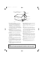 4
4
-
 5
5
-
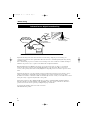 6
6
-
 7
7
-
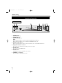 8
8
-
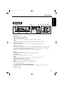 9
9
-
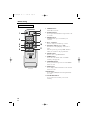 10
10
-
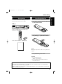 11
11
-
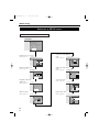 12
12
-
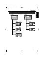 13
13
-
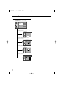 14
14
-
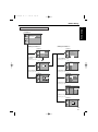 15
15
-
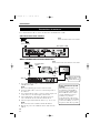 16
16
-
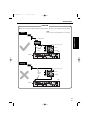 17
17
-
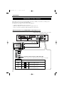 18
18
-
 19
19
-
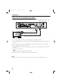 20
20
-
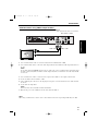 21
21
-
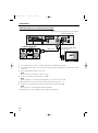 22
22
-
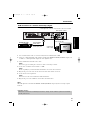 23
23
-
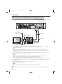 24
24
-
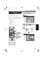 25
25
-
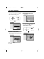 26
26
-
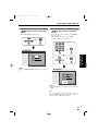 27
27
-
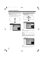 28
28
-
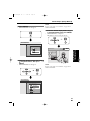 29
29
-
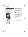 30
30
-
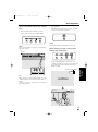 31
31
-
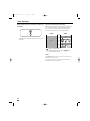 32
32
-
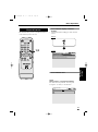 33
33
-
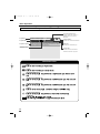 34
34
-
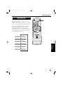 35
35
-
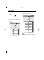 36
36
-
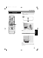 37
37
-
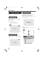 38
38
-
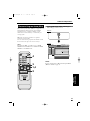 39
39
-
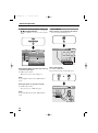 40
40
-
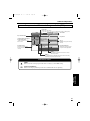 41
41
-
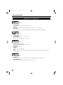 42
42
-
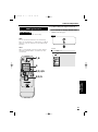 43
43
-
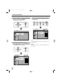 44
44
-
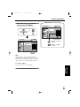 45
45
-
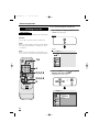 46
46
-
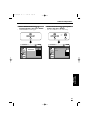 47
47
-
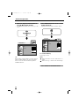 48
48
-
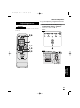 49
49
-
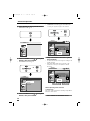 50
50
-
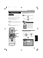 51
51
-
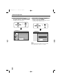 52
52
-
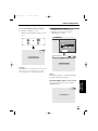 53
53
-
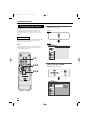 54
54
-
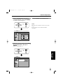 55
55
-
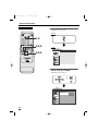 56
56
-
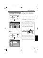 57
57
-
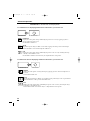 58
58
-
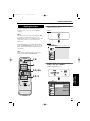 59
59
-
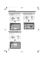 60
60
-
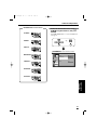 61
61
-
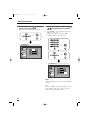 62
62
-
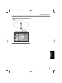 63
63
-
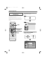 64
64
-
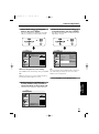 65
65
-
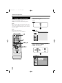 66
66
-
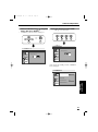 67
67
-
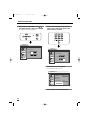 68
68
-
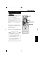 69
69
-
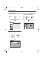 70
70
-
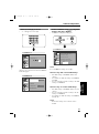 71
71
-
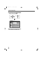 72
72
-
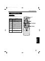 73
73
-
 74
74
-
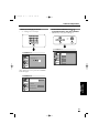 75
75
-
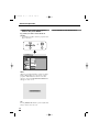 76
76
-
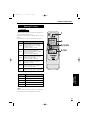 77
77
-
 78
78
-
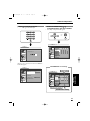 79
79
-
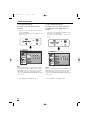 80
80
-
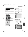 81
81
-
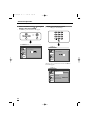 82
82
-
 83
83
-
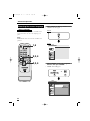 84
84
-
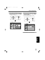 85
85
-
 86
86
-
 87
87
-
 88
88
-
 89
89
-
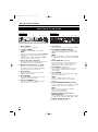 90
90
-
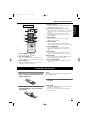 91
91
-
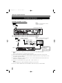 92
92
-
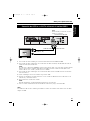 93
93
-
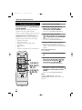 94
94
-
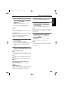 95
95
-
 96
96


Sylvania 6900DTD Manual de usuario
- Categoría
- Decodificadores de TV
- Tipo
- Manual de usuario
- Este manual también es adecuado para
en otros idiomas
- English: Sylvania 6900DTD User manual
Artículos relacionados
Otros documentos
-
Apex Digital Apex DT502 Manual de usuario
-
Hitachi Director's P50X901 Instrucciones de operación
-
-
Sanyo TV Receiver HT32744 Manual de usuario
-
Hitachi P55H401 Manual de usuario
-
-