ATEN 2-4 8 Port Video Splitter Guía de inicio rápido
- Categoría
- Divisores de video
- Tipo
- Guía de inicio rápido

VS132A/VS134A/VS138A 2-Port Video Splitter / 4/8 port Video Splitter
VS132A/VS134A/VS138A Répartiteur vidéo à 2/4/8 ports
VS132A/VS134A/VS138A 2-, 4- bzw. 8-Port-Grafi ksplitter
VS132A/VS134A/VS138A Repartidor gráfi co de 2/4/8 puertos
Requirements
Source Device
The following equipment must be installed on the computer or source
device that is acting as the source of video content:
• HDB-15 output connector(s)
Display Device
• A display device or receiver with an HDB-15 input connector for each
output port you will be installing
Cables
• A VGA cable for the source device you will be installing
• A VGA cable for each display device or receiver you will be installing
Note: VGA cables are not supplied with this package
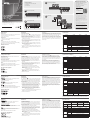
Hardware Review
Front View
A
1. Power LED
Rear View
B
1. Power Jack
2. Video In Port
3. Video Out Ports
Confi guration requise
Périphérique source
Les composants suivants doivent être installés sur l’ordinateur ou le
périphérique source vidéo :
• Connecteur(s) de sortie HDB-15
Périphérique d’affi chage
• Un périphérique d’affi chage ou un récepteur équipé d’un connecteur
d’entrée HDB-15 pour chaque port de sortie à confi gurer
Câbles
• Un câble VGA pour le périphérique source à installer
• Un câble VGA pour chaque périphérique d’affi chage ou récepteur à
installer
Remarque: aucun câble VGA n’est livré avec le produit.
Description de l’appareil
Vue avant
A
1. Voyant d’alimentation
Vue arrière
B
1. Prise d’alimentation
2. Port d’entrée vidéo
3. Ports de sortie vidéo
Voraussetzungen
Signalquelle
Auf den Signalquellen oder Computern, die das Grafi ksignal senden,
muss mindestens Folgendes installiert sein:
• HDB-15-Ausgangsbuchse(n)
Anzeigegerät
• Ein Anzeigegerät oder Receiver mit HDB-15-Eingang für jeden
Signalausgang, der installiert werden soll
Kabel
• Ein VGA-Kabel für die zu installierende Signalquelle
• Ein VGA-Kabel für jedes zu installierende Anzeigegerät bzw. Receiver
Hinweis: Die VGA-Kabel sind nicht im Lieferumfang enthalten.
Hardwareübersicht
Vorderseitige Ansicht
A
1. LED-Betriebsanzeige
Rückseitige Ansicht
B
1. Stromeingangsbuchse
2. Video-Eingang
3. Video-Ausgänge
Requisitos
Dispositivo fuente
En los dispositivos fuente de señal gráfi ca u ordenadores que se
conectan al equipo debe estar instalado lo siguiente:
• Conector(es) de salida HDB-15
Dispositivo de visualización
• Un dispositivo de visualización o un receptor con conector de entrada
HDB-15 para cada puerto de salida que desee utilizar
Cables
• Un cable VGA para el dispositivo fuente que desee instalar
• Un cable VGA para cada dispositivo de visualización o receptor que
desee instalar
Nota: los cables VGA no están incluidos con la unidad.
Presentación del hardware
Vista frontal
A
1. Indicador LED de alimentación
Vista posterior
B
1. Entrada de alimentación
2. Puerto de entrada de señal gráfi ca
3. Puertos de salida de señal gráfi ca
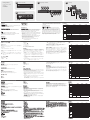
Installation
Single Stage Installation
C
Setting up the VS132
A
/ VS134
A
/ VS138
A
is simply a matter of
plugging in the cables. In a single stage installation, no additional video
splitters are cascaded down from the fi rst unit. Refer to the diagram as
you follow the step by step directions below:
1. Make sure that the computer and monitors you are using for the
installation are all powered off.
2. Plug the female end of a male-to-female VGA cable into the VS132
A
/ VS134
A
/ VS138
A
's Video In port.
3. Plug the male end of the VGA cable into the computer or source
device’s video output port.
4. Use 2/4/8 VGA cables to connect 2/4/8 displays to the VS132
A
/
VS134
A
/ VS138
A
’s Video Out ports.
Note: VGA cables do not come with the package. These must be
purchased separately.
5. Plug the power adapter (supplied with this package) into an AC
source; then plug the power adapter cable into the splitter’s power
jack.
6. Power on all equipment.
Installation
Installation simple
C
L’installation du répartiteur vidéo VS132
A
/ VS134
A
/ VS138
A
consiste
simplement à connecter les câbles. Dans une installation simple, aucun
répartiteur vidéo supplémentaire n’est installé en cascade à partir
du premier dispositif. Reportez-vous au schéma d’installation pour
effectuer les étapes suivantes :
1. Vérifi ez que l’ordinateur et les moniteurs de votre installation sont
tous éteints.
2. Branchez l’extrémité femelle du câble VGA mâle/femelle sur le port
d’entrée vidéo du VS132
A
/ VS134
A
/ VS138
A
.
3. Branchez l’extrémité mâle du câble VGA sur le port de sortie vidéo
de l’ordinateur ou du périphérique source.
4. Utilisez des câbles VGA pour 2/4/8 ports pour relier 2/4/8
périphériques d’affi chage aux ports de sortie vidéo du VS132
A
/
VS134
A
/ VS138
A
.
Remarque: aucun câble VGA n’est livré avec le produit. Ils doivent
être achetés séparément.
5. Branchez une extrémité de l’adaptateur secteur fourni sur une
prise de courant et l’autre extrémité sur la prise d’alimentation du
répartiteur vidéo.
6. Allumez tous les appareils.
Installation
Einzelinstallation
C
Die Installation des VS132
A
/ VS134
A
/ VS138
A
ist mit ein paar wenigen
Kabelanschlüssen erledigt: Als Einzelebene wird ein Aufbau bezeichnet,
in dem keine weiteren Grafi ksplitter hinter dem ersten Grafi ksplitter in
Reihe geschaltet werden. Für die Durchführung der folgenden Schritte,
siehe das Diagramm:
1. Schalten Sie alle zu installierenden Computer und Monitore aus.
2. Verbinden Sie den passenden Stecker (Weiblein) des VGA-Kabels
mit dem Grafi ksignaleingang am VS132
A
/ VS134
A
/ VS138
A
.
3. Verbinden Sie das andere Ende (Männlein) des VGA-Kabels mit dem
Grafi kkartenausgang am Computer bzw. der Grafi ksignalquelle.
4. Verwenden Sie 2/4/8 VGA-Kabel, um 2/4/8 Bildschirme mit den
Signalausgängen am VS132
A
/ VS134
A
/ VS138
A
zu verbinden.
Hinweis: Die VGA-Kabel sind nicht im Lieferumfang enthalten. Sie
müssen separat erworben werden.
5. Verbinden Sie das mitgelieferte Netzteil mit einer Steckdose und sein
Netzkabel mit der Stromeingangsbuchse des Splitters.
6. Schalten Sie alle Geräte ein.
Instalación
Instalación individual
C
La instalación del repartidor gráfi co VS132
A
/ VS134
A
/ VS138
A
es tan
sencilla como conectar unos cables. En una instalación individual, no
no se conectan más repartidores de señal gráfi ca en cascada a partir
de la primera unidad. Véase el diagrama de instalación cuando vaya a
efectuar los pasos siguientes:
1. Apague el ordenador y los monitores de su instalación.
2. Inserte el extremo hembra de un cable VGA macho a hembra en el
puerto de entrada de señal gráfi ca del VS132
A
/ VS134
A
/ VS138
A
.
3. Inserte el extremo macho del cable VGA en el puerto de salida de
señal gráfi cadel ordenador o del dispositivo fuente.
4. Utilice 2/4/8 cables VGA para conectar 2/4/8 dispositivos de
visualización a los puertos de salida de señal gráfi ca del VS132
A
/
VS134
A
/ VS138
A
.
Nota: los cables VGA no están incluidos con el dispositivo. Deben
adquirirse por separado.
5. Conecte el adaptador de alimentación incluido a una toma eléctrica,
y el cable del adaptador a la entrada de alimentación del repartidor
gráfi co.
6. Encienda todos los equipos.
Cascading
D
To provide video displays for more monitors, additional units can be
cascaded. Use a high-density HDB-15 male/female video extender
cable to connect any available Video Out port on the higher level
Video Splitter to the Video In port of the lower level video splitter.
You can cascade as many video splitters as there are ports avaliable,
and all three models can be mixed on the same chain. Theoretically,
there is no limit to the number of splitters that can be cascaded, but
the quality will deteriorate as you get further and further away from
the video signal.
Installation en cascade
D
Pour affi cher vos données sur d’autres moniteurs, vous pouvez
installer et brancher en cascade d’autres répartiteurs vidéo. Utilisez
un câble d’extension vidéo mâle/femelle HDB-15 de haute densité
pour relier un port de sortie Video Out disponible du répartiteur vidéo
de niveau supérieur au port d’entrée Video In du répartiteur vidéo de
niveau inférieur.
Vous pouvez installer en cascade autant de répartiteurs vidéo que
de ports disponibles. Les trois modèles de répartiteur peuvent
notamment être utilisés dans une même installation en cascade. En
théorie, vous pouvez installer un nombre illimité de répartiteurs en
cascade, mais notez que plus l’installation en cascade est complexe,
plus la qualité du signal vidéo s’en trouvera altérée.
Reihenschaltung
D
Um eine Bildausgabe auf weiteren Monitoren zu erhalten, können Sie
weitere Geräte in Reihe schalten. Verwenden Sie ein High-Density
HDB-15-VGA-Verlängerungskabel (Männlein/Weiblein), um einen
beliebigen Ausgang Video Out des höhergeordneten Grafi ksplitters
mit dem Signaleingang Video des Grafi ksplitters niedrigerer Ordnung
zu verbinden.
Sie können so viele Grafi ksplitter hintereinander schalten, wie Ports
verfügbar sind. Ebenso können alle drei Modelle innerhalb derselben
Kaskade vermischt werden. Theoretisch ist die Anzahl der zu
kaskadierenden Splitter unbegrenzt, allerdings verringert sich in der
Praxis die Bildqualität, je länger der Weg ist, den das Grafi ksignal
zurücklegen muss.
Instalación en cascada
D
Para ofrecer una visualización de la señal gráfi ca en más monitores,
puede conectar varios repartidores gráfi cos en cascada. Emplee un
cable de extensión gráfi ca macho/hembra HDB-15 de alta densidad
para conectar cualquier puerto de salida Video Out del repartidor
gráfi co de nivel superior a la entrada Video In del repartidor gráfi co de
nivel inferior.
Puede conectar en cascada tantos repartidores gráfi cos como haya
puertos disponibles. Además, los tres modelos pueden mezclarse en
la misma cascada. Teóricamente, el número de repartidores que se
puede conectar en cascada no viene limitado. No obstante, la calidad
de imagen se deteriora con la distancia que la señal gráfi ca tiene que
recorrer.
Specifi cations
Function VS132A VS134A VS138A
Display Connections 2/8* 4/64* 8/512*
Connectors
Video In 1 x HDB-15 Male
Video Out 2 x HDB-15 Female 4 x HDB-15 Female 8 x HDB-15 Female
Power 1 x DC Jack
LEDs Power 1 x Green
Video
Bandwidth 450 MHz 450 MHz 450 MHz
Resolution 2048 x 1536 @ 60Hz
Signal Type VGA, XGA, SVGA, UXGA, QXGA, Multisync, DDC2B**
Signal Range 30 m
Power Consumption DC 5V, 0.62W DC 5V, 0.9W DC 5V, 1.99W
Environment
Operating
Temp.
0–50ºC
Storage
Temp.
-20–60ºC
Humidity 0–80% RH, Non-condensing
Physical
Properties
Housing Metal
Weight 0.42 kg 0.61 kg 0.69 kg
Dimensions
(L x W x H)
13.00 x 7.51 x 4.40 cm 20.00 x 7.51 x 4.40 cm
* via three-level cascade
** Port 1 only
Spécifi cations techniques
Fonction VS132A VS134A VS138A
Ports de connexion pour
l'affi chage
2/8* 4/64* 8/512*
Connecteurs
Entrée vidéo 1 connecteur HDB-15 mâle
Sortie vidéo
2 connecteurs HDB-
15 femelle
4 connecteurs HDB-
15 femelle
8 connecteurs
HDB-15 femelle
Alimentation 1 prise d'alimentation C.C.
Voyants Alimentation 1 (vert)
Résolution
graphique
Bande passante 450 MHz 450 MHz 450 MHz
Résolution 2048 x 1536, 60 Hz
Type de signal VGA, XGA, SVGA, UXGA, QXGA, Multisync, DDC2B**
Portée du signal 30 m
Consommation électrique 5 V c.c., 0,62 W 5 V c.c., 0,9 W 5 V c.c., 1,99 W
Environnement
Température de
fonctionnement
0 à 50 ºC
Température de
stockage
-20 à 60 ºC
Humidité Humidité relative de 0 à 80 %, sans condensation
Propriétés
physiques
Carcasse Métallique
Poids 0,42 kg 0,61 kg 0,69 kg
Dimensions
(L x l x H)
13 x 7,51 x 4,40 cm 20 x 7,51 x 4,40 cm
* Avec cascade sur trois niveaux
** Port 1 uniquement
Technische Daten
Funktion VS132A VS134A VS138A
Monitoranschlüsse 2/8* 4/64* 8/512*
Anschlüsse
Grafi keingänge 1 x HDB-15 Männlein
Grafi kausgänge
2 x HDB-15
Weiblein
4 x HDB-15
Weiblein
8 x HDB-15
Weiblein
Stromversorgung 1 x Stromeingangsbuchse
LED-Anzeigen Stromversorgung 1 x grün
Bildschirm
Bandbreite 450 MHz 450 MHz 450 MHz
Aufl ösung 2048 x 1536 bei 60Hz
Signaltyp VGA, XGA, SVGA, UXGA, QXGA, Multisync, DDC2B**
Signal-Reichweite 30 m
Stromverbrauch 5 V=, 0,62 W 5 V=, 0,9 W 5 V=, 1,99 W
Umgebung
Betriebstemperatur 0 – 50 ºC
Lagertemperatur -20 – 60 ºC
Feuchtigkeit 0 -80% rel. Luftfeuchte, nicht kondensierend
Physische
Eigenschaften
Gehäuse Metall
Gewicht 0,42kg 0,61kg 0,69 kg
Abmessungen
(L x B x H)
13,00 x 7,51 x 4,40
cm
20,00 x 7,51 x 4,40 cm
* bei Reihenschaltung in drei Ebenen
** Nur Port 1
Achtung: Der Gebrauch dieses Geräts in Wohnumgebung kann Funkstörungen verursachen.
Especifi caciones
Función VS132A VS134A VS138A
Puertos de conexión para
pantalla
2/8* 4/64* 8/512*
Conectores
Entrada de vídeo 1 conector HDB-15 macho
Salida de vídeo
2 conectores HDB-
15 hembra
4 conectores HDB-
15 hembra
8 conectores HDB-
15 hembra
Alimentación 1 toma de c.c.
Indicadores
LED
Alimentación 1 (verde)
Resolución
gráfi ca
Ancho de banda 450 MHz 450 MHz 450 MHz
Resolución 2048 x 1536 a 60 Hz
Tipo de señal VGA, XGA, SVGA, UXGA, QXGA, Multisync, DDC2B**
Alcance de la señal 30 m
Consumo 5 V c.c., 0,62 W 5 V c.c., 0,9 W 5 V c.c., 1,99 W
Entorno
Temperatura de
funcionamiento
0 a 50 ºC
Temperatura de
almacenamiento
-20 a 60 ºC
Humedad 0 a 80% de HR, sin condensar
Propiedades
físicas
Carcasa Metálica
Peso 0,42 kg 0,61 kg 0,69 kg
Dimensiones
(L x An x Al)
13 x 7,51 x 4,40 cm 20 x 7,51 x 4,40 cm
* Mediante conexión en cascada de tres niveles
** Puerto 1 únicamente
Support and Documentation Notice
All information, documentation, fi rmware,
software utilities, and specifi cations contained in
this package are subject to change without prior
notifi cation by the manufacturer.
To reduce the environmental impact of our
products, ATEN documentation and software can
be found online at
http://www.aten.com/download/
Technical Support
www.aten.com/support
이 기기는 업무용(A급) 전자파적합기기로서 판매자 또는 사용자는 이 점을
주의하시기 바라며, 가정외의 지역에서 사용하는 것을 목적으로 합니다.
EMC Information
FEDERAL COMMUNICATIONS COMMISSION INTERFERENCE
STATEMENT:
This equipment has been tested and found to comply with the limits
for a Class A digital device, pursuant to Part 15 of the FCC Rules.
These limits are designed to provide reasonable protection against
harmful interference when the equipment is operated in a commercial
environment. This equipment generates, uses, and can radiate radio
frequency energy and, if not installed and used in accordance with
the instruction manual, may cause harmful interference to radio
communications. Operation of this equipment in a residential area
is likely to cause harmful interference in which case the user will be
required to correct the interference at his own expense.
FCC Caution: Any changes or modifi cations not expressly approved by
the party responsible for compliance could void the user's authority to
operate this equipment.
Warning: Operation of this equipment in a residential environment
could cause radio interference.
This device complies with Part 15 of the FCC Rules. Operation is subject
to the following two conditions:(1) this device mat not cause harmful
interference, and(2) this device must accept any interference received,
including interference that may cause undesired operation.
Important. Before proceeding, download the Installation and
Operation Manual by visiting the website, www.aten.com and
navigating to the product page. The manual includes important
warnings, loading specifi cations and grounding instructions.
Scan for
more information
© Copyright 2019 ATEN
®
International Co., Ltd.
ATEN and the ATEN logo are trademarks of ATEN International Co., Ltd. All rights reserved. All
other trademarks are the property of their respective owners.
Part No. PAPE-1285-V00G Printing Date: 10/2019
2-Port Video Splitter
4/8 port Video Splitter
Quick Start Guide
VS132A/VS134A/VS138A
1 VS132A / VS134A / VS138A Video Splitter
1 Power Adapter
1 Quick Start Guide
Package Contents:
www.aten.com
www.aten.com
www.aten.com
www.aten.com
Front View (VS138A)
Rear View (VS138A)
A
B
Single Stage Installation
Cascading
C
D
1
1
31 2
5
3
2 4
La página se está cargando ...
Transcripción de documentos
C Package Contents: Support and Documentation Notice All information, documentation, firmware, software utilities, and specifications contained in this package are subject to change without prior notification by the manufacturer. To reduce the environmental impact of our products, ATEN documentation and software can be found online at http://www.aten.com/download/ Single Stage Installation 1 VS132A / VS134A / VS138A Video Splitter 1 Power Adapter 1 Quick Start Guide Technical Support www.aten.com/support 5 A Front View (VS138A) 2 4 Scan for more information 3 EMC Information VS132A/VS134A/VS138A 11 2-Port Video Splitter 4/8 port Video Splitter Quick Start Guide © Copyright 2019 ATEN® International Co., Ltd. B D FEDERAL COMMUNICATIONS COMMISSION INTERFERENCE STATEMENT: This equipment has been tested and found to comply with the limits for a Class A digital device, pursuant to Part 15 of the FCC Rules. These limits are designed to provide reasonable protection against harmful interference when the equipment is operated in a commercial environment. This equipment generates, uses, and can radiate radio frequency energy and, if not installed and used in accordance with the instruction manual, may cause harmful interference to radio communications. Operation of this equipment in a residential area is likely to cause harmful interference in which case the user will be required to correct the interference at his own expense. FCC Caution: Any changes or modifications not expressly approved by the party responsible for compliance could void the user's authority to operate this equipment. Warning: Operation of this equipment in a residential environment could cause radio interference. Cascading Rear View (VS138A) This device complies with Part 15 of the FCC Rules. Operation is subject to the following two conditions:(1) this device mat not cause harmful interference, and(2) this device must accept any interference received, including interference that may cause undesired operation. ATEN and the ATEN logo are trademarks of ATEN International Co., Ltd. All rights reserved. All other trademarks are the property of their respective owners. Part No. PAPE-1285-V00G Printing Date: 10/2019 Important. Before proceeding, download the Installation and Operation Manual by visiting the website, www.aten.com and navigating to the product page. The manual includes important warnings, loading specifications and grounding instructions. 1 2 3 이 기기는 업무용(A급) 전자파적합기기로서 판매자 또는 사용자는 이 점을 주의하시기 바라며, 가정외의 지역에서 사용하는 것을 목적으로 합니다. VS132A/VS134A/VS138A 2-Port Video Splitter / 4/8 port Video Splitter www.aten.com Cascading Requirements Installation Source Device Single Stage Installation The following equipment must be installed on the computer or source device that is acting as the source of video content: • HDB-15 output connector(s) Display Device • A display device or receiver with an HDB-15 input connector for each output port you will be installing Cables • A VGA cable for the source device you will be installing • A VGA cable for each display device or receiver you will be installing Note: VGA cables are not supplied with this package Hardware Review Front View A 1. Power LED Rear View C Setting up the VS132 A / VS134 A / VS138 A is simply a matter of plugging in the cables. In a single stage installation, no additional video splitters are cascaded down from the first unit. Refer to the diagram as you follow the step by step directions below: 1. Make sure that the computer and monitors you are using for the installation are all powered off. 2. Plug the female end of a male-to-female VGA cable into the VS132A / VS134A / VS138A's Video In port. 3. Plug the male end of the VGA cable into the computer or source device’s video output port. 4. Use 2/4/8 VGA cables to connect 2/4/8 displays to the VS132 A / VS134A / VS138A’s Video Out ports. Note: VGA cables do not come with the package. These must be purchased separately. 5. Plug the power adapter (supplied with this package) into an AC source; then plug the power adapter cable into the splitter’s power jack. 6. Power on all equipment. D To provide video displays for more monitors, additional units can be cascaded. Use a high-density HDB-15 male/female video extender cable to connect any available Video Out port on the higher level Video Splitter to the Video In port of the lower level video splitter. You can cascade as many video splitters as there are ports avaliable, and all three models can be mixed on the same chain. Theoretically, there is no limit to the number of splitters that can be cascaded, but the quality will deteriorate as you get further and further away from the video signal. B 1. Power Jack 2. Video In Port 3. Video Out Ports Specifications Function Display Connections Video In Connectors Video Out Power LEDs Power Bandwidth Video Resolution Signal Type Signal Range Power Consumption Operating Temp. Environment Storage Temp. Humidity Housing Physical Weight Properties Dimensions (L x W x H) VS132A 2/8* VS134A VS138A 4/64* 8/512* 1 x HDB-15 Male 2 x HDB-15 Female 4 x HDB-15 Female 8 x HDB-15 Female 1 x DC Jack 1 x Green 450 MHz 450 MHz 450 MHz 2048 x 1536 @ 60Hz VGA, XGA, SVGA, UXGA, QXGA, Multisync, DDC2B** 30 m DC 5V, 0.62W DC 5V, 0.9W DC 5V, 1.99W 0–50ºC -20–60ºC 0.42 kg 0–80% RH, Non-condensing Metal 0.61 kg 13.00 x 7.51 x 4.40 cm 20.00 x 7.51 x 4.40 cm * via three-level cascade ** Port 1 only VS132A/VS134A/VS138A Répartiteur vidéo à 2/4/8 ports www.aten.com Installation en cascade Configuration requise Installation Périphérique source Installation simple Les composants suivants doivent être installés sur l’ordinateur ou le périphérique source vidéo : • Connecteur(s) de sortie HDB-15 Périphérique d’affichage • Un périphérique d’affichage ou un récepteur équipé d’un connecteur d’entrée HDB-15 pour chaque port de sortie à configurer Câbles • Un câble VGA pour le périphérique source à installer • Un câble VGA pour chaque périphérique d’affichage ou récepteur à installer Remarque: aucun câble VGA n’est livré avec le produit. Description de l’appareil Vue avant A 1. Voyant d’alimentation Vue arrière B 1. Prise d’alimentation 2. Port d’entrée vidéo 3. Ports de sortie vidéo C L’installation du répartiteur vidéo VS132A / VS134A / VS138A consiste simplement à connecter les câbles. Dans une installation simple, aucun répartiteur vidéo supplémentaire n’est installé en cascade à partir du premier dispositif. Reportez-vous au schéma d’installation pour effectuer les étapes suivantes : 1. Vérifiez que l’ordinateur et les moniteurs de votre installation sont tous éteints. 2. Branchez l’extrémité femelle du câble VGA mâle/femelle sur le port d’entrée vidéo du VS132A / VS134A / VS138A. 3. Branchez l’extrémité mâle du câble VGA sur le port de sortie vidéo de l’ordinateur ou du périphérique source. 4. Utilisez des câbles VGA pour 2/4/8 ports pour relier 2/4/8 périphériques d’affichage aux ports de sortie vidéo du VS132A / VS134A / VS138A. Remarque: aucun câble VGA n’est livré avec le produit. Ils doivent être achetés séparément. 5. Branchez une extrémité de l’adaptateur secteur fourni sur une prise de courant et l’autre extrémité sur la prise d’alimentation du répartiteur vidéo. 6. Allumez tous les appareils. D Pour afficher vos données sur d’autres moniteurs, vous pouvez installer et brancher en cascade d’autres répartiteurs vidéo. Utilisez un câble d’extension vidéo mâle/femelle HDB-15 de haute densité pour relier un port de sortie Video Out disponible du répartiteur vidéo de niveau supérieur au port d’entrée Video In du répartiteur vidéo de niveau inférieur. Vous pouvez installer en cascade autant de répartiteurs vidéo que de ports disponibles. Les trois modèles de répartiteur peuvent notamment être utilisés dans une même installation en cascade. En théorie, vous pouvez installer un nombre illimité de répartiteurs en cascade, mais notez que plus l’installation en cascade est complexe, plus la qualité du signal vidéo s’en trouvera altérée. Spécifications techniques Fonction Ports de connexion pour l'affichage Entrée vidéo VS132A VS134A VS138A 2/8* 4/64* 8/512* 1 connecteur HDB-15 mâle 2 connecteurs HDB- 4 connecteurs HDB8 connecteurs Connecteurs Sortie vidéo 15 femelle 15 femelle HDB-15 femelle Alimentation 1 prise d'alimentation C.C. Voyants Alimentation 1 (vert) Bande passante 450 MHz 450 MHz 450 MHz Résolution graphique Résolution 2048 x 1536, 60 Hz Type de signal VGA, XGA, SVGA, UXGA, QXGA, Multisync, DDC2B** Portée du signal 30 m Consommation électrique 5 V c.c., 0,62 W 5 V c.c., 0,9 W 5 V c.c., 1,99 W Température de 0 à 50 ºC fonctionnement Environnement Température de -20 à 60 ºC stockage Humidité Humidité relative de 0 à 80 %, sans condensation Carcasse Métallique Propriétés Poids 0,42 kg 0,61 kg 0,69 kg physiques Dimensions 13 x 7,51 x 4,40 cm 20 x 7,51 x 4,40 cm (L x l x H) * Avec cascade sur trois niveaux ** Port 1 uniquement VS132A/VS134A/VS138A 2-, 4- bzw. 8-Port-Grafiksplitter www.aten.com Voraussetzungen Installation Signalquelle Einzelinstallation Auf den Signalquellen oder Computern, die das Grafiksignal senden, muss mindestens Folgendes installiert sein: • HDB-15-Ausgangsbuchse(n) Anzeigegerät • Ein Anzeigegerät oder Receiver mit HDB-15-Eingang für jeden Signalausgang, der installiert werden soll Kabel • Ein VGA-Kabel für die zu installierende Signalquelle • Ein VGA-Kabel für jedes zu installierende Anzeigegerät bzw. Receiver Hinweis: Die VGA-Kabel sind nicht im Lieferumfang enthalten. Hardwareübersicht Vorderseitige Ansicht A 1. LED-Betriebsanzeige Rückseitige Ansicht 0.69 kg Reihenschaltung C Die Installation des VS132A / VS134A / VS138A ist mit ein paar wenigen Kabelanschlüssen erledigt: Als Einzelebene wird ein Aufbau bezeichnet, in dem keine weiteren Grafiksplitter hinter dem ersten Grafiksplitter in Reihe geschaltet werden. Für die Durchführung der folgenden Schritte, siehe das Diagramm: 1. Schalten Sie alle zu installierenden Computer und Monitore aus. 2. Verbinden Sie den passenden Stecker (Weiblein) des VGA-Kabels mit dem Grafiksignaleingang am VS132A / VS134A / VS138A. 3. Verbinden Sie das andere Ende (Männlein) des VGA-Kabels mit dem Grafikkartenausgang am Computer bzw. der Grafiksignalquelle. 4. Verwenden Sie 2/4/8 VGA-Kabel, um 2/4/8 Bildschirme mit den Signalausgängen am VS132A / VS134A / VS138A zu verbinden. Hinweis: Die VGA-Kabel sind nicht im Lieferumfang enthalten. Sie müssen separat erworben werden. 5. Verbinden Sie das mitgelieferte Netzteil mit einer Steckdose und sein Netzkabel mit der Stromeingangsbuchse des Splitters. 6. Schalten Sie alle Geräte ein. D Um eine Bildausgabe auf weiteren Monitoren zu erhalten, können Sie weitere Geräte in Reihe schalten. Verwenden Sie ein High-Density HDB-15-VGA-Verlängerungskabel (Männlein/Weiblein), um einen beliebigen Ausgang Video Out des höhergeordneten Grafiksplitters mit dem Signaleingang Video des Grafiksplitters niedrigerer Ordnung zu verbinden. Sie können so viele Grafiksplitter hintereinander schalten, wie Ports verfügbar sind. Ebenso können alle drei Modelle innerhalb derselben Kaskade vermischt werden. Theoretisch ist die Anzahl der zu kaskadierenden Splitter unbegrenzt, allerdings verringert sich in der Praxis die Bildqualität, je länger der Weg ist, den das Grafiksignal zurücklegen muss. Technische Daten Funktion Monitoranschlüsse Grafikeingänge Anschlüsse VS132A VS134A VS138A 2/8* 4/64* 8/512* 1 x HDB-15 Männlein 2 x HDB-15 4 x HDB-15 8 x HDB-15 Weiblein Weiblein Weiblein 1 x Stromeingangsbuchse Grafikausgänge Stromversorgung LED-Anzeigen Stromversorgung 1 x grün Bandbreite Bildschirm 450 MHz Auflösung 450 MHz Signaltyp VGA, XGA, SVGA, UXGA, QXGA, Multisync, DDC2B** Signal-Reichweite 30 m Stromverbrauch 5 V=, 0,62 W Betriebstemperatur Umgebung 5 V=, 1,99 W -20 – 60 ºC 0 -80% rel. Luftfeuchte, nicht kondensierend Gehäuse Metall Physische Gewicht Eigenschaften Abmessungen (L x B x H) 1. Stromeingangsbuchse 2. Video-Eingang 3. Video-Ausgänge 5 V=, 0,9 W 0 – 50 ºC Lagertemperatur Feuchtigkeit B 450 MHz 2048 x 1536 bei 60Hz 0,42kg 13,00 x 7,51 x 4,40 cm 0,61kg 0,69 kg 20,00 x 7,51 x 4,40 cm * bei Reihenschaltung in drei Ebenen ** Nur Port 1 Achtung: Der Gebrauch dieses Geräts in Wohnumgebung kann Funkstörungen verursachen. VS132A/VS134A/VS138A Repartidor gráfico de 2/4/8 puertos www.aten.com Requisitos Instalación Dispositivo fuente Instalación individual En los dispositivos fuente de señal gráfica u ordenadores que se conectan al equipo debe estar instalado lo siguiente: • Conector(es) de salida HDB-15 Dispositivo de visualización • Un dispositivo de visualización o un receptor con conector de entrada HDB-15 para cada puerto de salida que desee utilizar Cables • Un cable VGA para el dispositivo fuente que desee instalar • Un cable VGA para cada dispositivo de visualización o receptor que desee instalar Nota: los cables VGA no están incluidos con la unidad. Presentación del hardware Vista frontal A 1. Indicador LED de alimentación Vista posterior B 1. Entrada de alimentación 2. Puerto de entrada de señal gráfica 3. Puertos de salida de señal gráfica Instalación en cascada C La instalación del repartidor gráfico VS132A / VS134A / VS138A es tan sencilla como conectar unos cables. En una instalación individual, no no se conectan más repartidores de señal gráfica en cascada a partir de la primera unidad. Véase el diagrama de instalación cuando vaya a efectuar los pasos siguientes: 1. Apague el ordenador y los monitores de su instalación. 2. Inserte el extremo hembra de un cable VGA macho a hembra en el puerto de entrada de señal gráfica del VS132A / VS134A / VS138A. 3. Inserte el extremo macho del cable VGA en el puerto de salida de señal gráficadel ordenador o del dispositivo fuente. 4. Utilice 2/4/8 cables VGA para conectar 2/4/8 dispositivos de visualización a los puertos de salida de señal gráfica del VS132A / VS134A / VS138A. Nota: los cables VGA no están incluidos con el dispositivo. Deben adquirirse por separado. 5. Conecte el adaptador de alimentación incluido a una toma eléctrica, y el cable del adaptador a la entrada de alimentación del repartidor gráfico. 6. Encienda todos los equipos. D Para ofrecer una visualización de la señal gráfica en más monitores, puede conectar varios repartidores gráficos en cascada. Emplee un cable de extensión gráfica macho/hembra HDB-15 de alta densidad para conectar cualquier puerto de salida Video Out del repartidor gráfico de nivel superior a la entrada Video In del repartidor gráfico de nivel inferior. Puede conectar en cascada tantos repartidores gráficos como haya puertos disponibles. Además, los tres modelos pueden mezclarse en la misma cascada. Teóricamente, el número de repartidores que se puede conectar en cascada no viene limitado. No obstante, la calidad de imagen se deteriora con la distancia que la señal gráfica tiene que recorrer. Especificaciones Función Puertos de conexión para pantalla Entrada de vídeo Conectores Salida de vídeo Alimentación Indicadores Alimentación LED Resolución Ancho de banda gráfica Resolución Tipo de señal Alcance de la señal Consumo Temperatura de funcionamiento Entorno Temperatura de almacenamiento Humedad Carcasa Propiedades Peso físicas Dimensiones (L x An x Al) VS132A VS134A VS138A 2/8* 4/64* 8/512* 1 conector HDB-15 macho 2 conectores HDB- 4 conectores HDB- 8 conectores HDB15 hembra 15 hembra 15 hembra 1 toma de c.c. 1 (verde) 450 MHz 450 MHz 450 MHz 2048 x 1536 a 60 Hz VGA, XGA, SVGA, UXGA, QXGA, Multisync, DDC2B** 30 m 5 V c.c., 0,62 W 5 V c.c., 0,9 W 5 V c.c., 1,99 W 0 a 50 ºC -20 a 60 ºC 0,42 kg 0 a 80% de HR, sin condensar Metálica 0,61 kg 13 x 7,51 x 4,40 cm * Mediante conexión en cascada de tres niveles ** Puerto 1 únicamente 0,69 kg 20 x 7,51 x 4,40 cm-
 1
1
-
 2
2


ATEN 2-4 8 Port Video Splitter Guía de inicio rápido
- Categoría
- Divisores de video
- Tipo
- Guía de inicio rápido
En otros idiomas
Documentos relacionados
-
ATEN VS132 Manual de usuario
-
ATEN VS98A 2/4/8-Port Video Splitter Guía de inicio rápido
-
ATEN VS92A Guía de inicio rápido
-
ATEN VS881 Guía de inicio rápido
-
-
ATEN VS1508 Guía de inicio rápido
-
-
ATEN VS0116 Guía de inicio rápido
-
-