
VS-92A / VS-94A / VS-98A
Répartiteur graphique à 2/4/8 ports VS92A/VS94A/VS98A
2/4/8-Port-VGA-Splitter VS92A/VS94A/VS98A
Repartidor gráfi co de 2/4/8 puertos - VS92A/VS94A/VS98A
Requirements
Source Device
The following equipment must be installed on the computer or source device that
acts at the source of video content:
• HDB-15 Output Connector
Display Device(s)
A display device with an HDB-15 input connector for each output port you will
be installing.
Notes:
1. The VS92A/VS94A/VS98A supports VGA, XGA, UXGA, WUXGA and
multisync monitors.
2. If you connect a DDC type monitor the Video Out Port 1, all other monitors
must be able to support the highest resolution that the DDC monitor can
provide.
Cables
• A high density HDB-15 video extender cable for the video source device
• A high density HDB-15 video extender cable for each display device
you will be installing
Confi guration minimale
Périphérique source
L’équipement suivant doit être installé sur l’ordinateur ou le périphérique utilisé
comme source de contenu graphique :
• Connecteur de sortie HDB-15
Périphérique(s) d’affichage
Un périphérique d’affi chage avec connecteur d’entrée HDB-15 pour chaque port
de sortie à confi gurer
Remarques :
1. Le VS92A/VS94A/VS98A est compatible avec les moniteurs VGA, XGA,
UXGA, WUXGA et multisync.
2. Si vous connectez un moniteur de type DDC au port 1 de sortie vidéo, tous les
autres moniteurs doivent pouvoir prendre en charge la résolution la plus haute
que le moniteur DDC peut fournir.
Câbles
• Un câble d’extension graphique HDB-15 à haute densité pour le périphérique
graphique source.
• Un câble d’extension graphique HDB-15 à haute densité pour chaque
périphérique d’affi chage faisant partie de l’installation.
Voraussetzungen
Signalquelle
Auf den Signalquellen oder Computern, die das Grafiksignal senden, muss
mindestens Folgendes installiert sein:
• HDB-15-Ausgangsbuchse
Anzeigegerät(e)
Ein Anzeigegerät mit HDB-15-Eingang für jeden Signalausgang, der installiert
werden soll
Hinweise:
1. Der VS92A/VS94A/VS98A unterstützt VGA-, XGA-, UXGA-, WUXGA- und
Multisync-Monitore.
2. Wenn Sie einen DDC-Monitor an den Video-Ausgang 1 anschließen, müssen
alle anderen Monitore ebenfalls die höchste Aufl ösung unterstützen, die der
DDC-Monitor unterstützt.
Kabel
• Ein High-Hensity HDB-15-Grafi kverlängerungskabel für die Grafi ksignalquelle
• Ein High-Hensity HDB-15-Grafi kverlängerungskabel für jeden anzuschließenden
Bildschirm
Requisitos
Dispositivo fuente
En los dispositivos fuente de señal gráfica u ordenadores que se conectan al
equipo debe estar instalado lo siguiente:
• Toma de salida HDB-15
Dispositivo(s) de visualización
Un dispositivo de visualización con conector de entrada HDB-15 para cada
puerto de salida que desee utilizar
Notas:
1. El VS92A/VS94A/VS98A admite monitores VGA, XGA, UXGA, WUXGA y
Multisync.
2. Si conecta un monitor que admita la señal DDC al puerto de salida de vídeo 1,
todos los demás monitores deben admitir la resolución máxima posible para el
monitor DDC.
Cables
• Un cable alargador HDB-15 de alta densidad para el dispositivo fuente
• Un cable alargador HDB-15 de alta densidad para cada dispositivo de
visualización que desee instalar
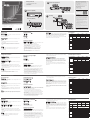
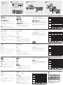
Hardware Review
A
Front View
1. Power LED
Rear View
2. Power Jack
3. Video In Port
4. Video Out Ports
Hardware Installation
Single Stage Installation
B
In a single stage installation, no additional video splitters are cascaded from the fi rst
unit. To set up a single stage installation, do the following:
1. Use a high density HDB-15 male/female video extender cable to
connect the PC or source device’s video port to the Video In port on the
rear of the Video Splitter.
2. Use 2/4/8 high density HDB-15 male/female video extender cables to
connect 2/4/8 monitors/display devices to the Video Splitter’s Video Out
ports located on the rear panel.
3. Plug the power adapter that came with the package into an AC power
source; plug the power adapter cable into the Video Splitter’s power
jack.
4. Power on the Video splitter; power on the monitors/display devices;
power on the PC/source device.
Description de l’appareil
A
Vue avant
1. Voyant d’alimentation
Vue arrière
2. Prise d’alimentation
3. Port d’entrée vidéo
4. Ports de sortie vidéo
Installation du matériel
Installation simple
B
Dans une installation simple, aucun répartiteur graphique supplémentaire n’est
installé en cascade à partir du premier dispositif. Pour mettre en place une
installation simple, procédez comme suit :
1. Utilisez un câble d’extension graphique mâle/femelle HDB-15 à haute densité
pour connecter le port graphique de l’ordinateur ou du périphérique source au
port d’entrée graphique à l’arrière du répartiteur graphique.
2. Utilisez des câbles d’extension graphiques mâles/femelles HDB-15 à haute
densité pour connecter 2/4/8 moniteurs/périphériques d’affi chage aux ports de
sortie graphiques à l’arrière du répartiteur graphique.
3. Branchez l’adaptateur secteur fourni avec le répartiteur sur une prise de courant
et sur la prise d’alimentation du répartiteur graphique.
Hardwareübersicht
A
Vorderseitige Ansicht
1. LED-Betriebsanzeige
Rückseitige Ansicht
2. Stromeingangsbuchse
3. Video-Eingang
4. Video-Ausgänge
Hardware installieren
Einzelinstallation
B
Als Einzelebene wird ein Aufbau bezeichnet, in dem keine weiteren Grafi ksplitter
hinter dem ersten Grafiksplitter in Reihe geschaltet werden. Zum Aufbau einer
Einzelinstallation gehen Sie folgendermaßen vor:
1. Verbinden Sie den Ausgang der Grafi kkarte des Computers oder der
Grafi ksignalquelle mit dem Grafi keingang auf der Rückseite des Splitters.
Verwenden Sie dazu ein High-Density HDB-15-VGA-Grafi kverlängerungskabel
Männlein/Weiblein.
2. Verbinden Sie die Ausgänge auf der Rückseite des Splitters mit 2, 4 bzw. 8
Monitoren bzw. Anzeigegeräten. Verwenden Sie dazu 2, 4 bzw. 8 High-Density
HDB-15-VGA-Grafi kverlängerungskabel Männlein/Weiblein.
3. Verbinden Sie das mitgelieferte Netzteil mit einer stromführenden Steckdose
und anschließend mit der Netzeingangsbuchse am Splitter.
Presentación del hardware
A
Vista frontal
1. Indicador LED de alimentación
Vista posterior
2. Entrada de alimentación
3. Puerto de entrada de señal gráfi ca
4. Puertos de salida de señal gráfi ca
Instalación del hardware
Instalación individual
B
En una instalación individual, no se conectan más repartidores de señal gráfi ca en
cascada a partir de la primera unidad. Para confi gurar una instalación individual,
haga lo siguiente:
1. Conecte la salida de la tarjeta gráfi ca del ordenador o dispositivo fuente al
puerto de entrada de señal Video In en la parte posterior del repartidor gráfi co.
Para ello, utilice un cable HDB-15 macho a hembra de alta densidad.
2. Conecte 2, 4 u 8 monitores o dispositivos de visualización a las salidas Video
Out en la parte posterior del repartidor gráfi co. Para ello, utilice 2, 4 u 8 cables
HDB-15 macho a hembra de alta densidad.
3. Conecte el adaptador de alimentación incluido a una toma eléctrica y el cable
del adaptador a la entrada de alimentación del repartidor gráfi co.
www.aten.com
www.aten.com
www.aten.com
www.aten.com
Cascading
C
To provide even more displays, additional units can be cascaded from the Video
Splitter’s Output ports. Simply use additional high density HDB-15 male/female video
extender cables to connect any available Video Out on the parent splitter to the
Video In port on the child splitter. See number 5 in the installation diagram.
You can cascade as many VS92A/VS94A/VS98A units as there are ports available,
and all three models can be mixed on the same cascade.
4. Allumez le répartiteur graphique ; allumez les moniteurs/périphériques d’affi chage;
allumez l’ordinateur/périphérique source.
Installation en cascade
C
Afi n de pouvoir utiliser encore plus d’écrans, vous pouvez installer des unités
supplémentaires en cascade depuis les ports de sortie du répartiteur graphique.
Utilisez simplement des câbles d’extension graphiques mâles/femelles HDB-15 à
haute densité supplémentaires pour connecter toute sortie graphique disponible sur
le répartiteur parent au port d’entrée graphique du répartiteur enfant. Voir numéro 5
sur le schéma d’installation.
Vous pouvez installer en cascade autant d’unités VS92A/VS94A/VS98A qu’il y a
de ports disponibles, et les trois modèles peuvent être utilisés conjointement sur la
même cascade.
4. Schalten Sie den Grafi ksplitter, die Monitore/Anzeigegeräte und den Computer
bzw. die Grafi ksignalquelle ein.
Reihenschaltung
C
Um noch mehr Displays anschließen zu können, lassen sich weitere Geräte an den
Signalausgängen des Grafi ksplitters kaskadieren. Verwenden Sie einfach zusätzliche
High-Density HDB-15-Grafikverlängerungskabel (Männlein/Weiblein), um einen
beliebigen Ausgang Video Out des Splitters erster Ordnung mit dem Signaleingang
Video In eines untergeordneten Splitters zu verbinden. Siehe die Nummer 5 im
Installationsdiagramm.
Sie können so viele VS92A/VS94A/VS98A hintereinander schalten, wie Ports
verfügbar sind. Ebenso können alle drei Modelle innerhalb derselben Kaskade
vermischt werden.
4. Encienda el repartidor gráfi co, encienda los monitores/dispositivos de visualización
y encienda el ordenador o la fuente de señal.
Instalación en cascada
C
Para poder conectar más pantallas HDMI, es posible conectar varias unidades en
cascada en los puertos de salida del repartidor gráfi co. Emplee cables de extensión
de vídeo HDB-15 macho/hembra de alta densidad adicionales para conectar
cualquier puerto de salida de Video Out del repartidor gráfi co de primer orden a la
entrada Video In del repartidor gráfi co subordinado. Véase el número 5 del diagrama
de instalación.
Puede conectar en cascada tantos VS92A/VS94A/VS98A como haya puertos
disponibles. Además, los tres modelos pueden mezclarse en la misma cascada.
Specifi cations
Function VS92A VS94A VS98A
Display Connections 2 / 8* 4 / 64* 8 / 512*
Connectors
Video In 1 x HDB-15 Male
Video Out
2 x HDB-15
Female
4 x HDB-15
Female
8 x HDB-15
Female
Power 1 x DC Jack
LEDs Power 1 (orange)
Video
Resolution 1920 x 1440 @ 60 Hz
Bandwidth 350 MHz 300 MHz
Cable Distance 65 m
Power Consumption DC9V, 1.24W DC9V, 2.03W DC9V, 3.94W
Environment
Operating
Temp.
0–50°C
Storage
Temp.
-20–60°C
Humidity 0–80% RH, Non-condensing
Physical
Properties
Housing Metal
Weight 0.42 kg 0.61 kg 0.69 kg
Dimensions
(L x W x H)
13.00 x 7.50 x
4.50 cm
20.00 x 7.50 x 4.50 cm
* Display connections in three-level cascade
Caractéristiques techniques
Fonction VS92A VS94A VS98A
Connexions pour l’affi chage 2 / 8* 4 / 64* 8 / 512*
Connecteurs
Entrée
graphique
1 connecteur HDB-15 mâle
Sortie
graphique
2 connecteurs
HDB-15
femelles
4 connecteurs
HDB-15
femelles
8 connecteurs
HDB-15
femelles
Alimentation 1 prise d’alimentation c.c.
Voyants Alimentation 1 (orange)
Signal
graphique
Résolution 1920 x 1440 à 60 Hz
Bande
passante
350 MHz 300 MHz
Longueur de câble 65 m
Consommation électrique c.c. 9 V, 1,24 W c.c. 9 V, 2,03 W c.c. 9 V, 3,94 W
Environnement
Température de
fonctionnement
0 à 50 °C
Température de
stockage
-20 à 60 °C
Humidité Humidité relative de 0 à 80 %, sans condensation
Propriétés
physiques
Boîtier Métallique
Poids 0,42 kg 0,61 kg 0,69 kg
Dimensions
(Long. x Larg. x
Haut.)
13.00 x 7.50 x
4.50 cm
20.00 x 7.50 x 4.50 cm
*Connexion d’écrans en cascade à trois niveaux
Technische Daten
Funktion VS92A VS94A VS98A
Monitoranschlüsse 2 / 8* 4 / 64* 8 / 512*
Anschlüsse
Grafi keingänge 1 x HDB-15 Männlein
Grafi kausgänge
2 x HDB-15
Weiblein
4 x HDB-15
Weiblein
8 x HDB-15
Weiblein
Stromversorgung 1 x Stromeingangsbuchse
LED-Anzeigen Stromversorgung 1 (orange)
Bildschirm
Aufl ösung 1920 x 1440 bei 60 Hz
Bandbreite 350 MHz 300 MHz
Kabellänge 65 m
Stromverbrauch 9 V=, 1,24 W 9 V=, 2,03 W 9 V=, 3,94 W
Umgebung
Betriebstemperatur 0–50 °C
Lagertemperatur -20-60 °C
Feuchtigkeit 0 -80% rel. Luftfeuchte, nicht kondensierend
Physische
Eigenschaften
Gehäuse Metall
Gewicht 0,42 kg 0,61 kg 0,69 kg
Abmessungen
(L x B x H)
13,00 x 7,50 x
4,50 cm
20,00 x 7,50 x 4,50 cm
* Display-Reihenschaltung in drei Ebenen
Especifi caciones
Función VS92A VS94A VS98A
Puertos de conexión para
pantalla
2 / 8* 4 / 64* 8 / 512*
Conectores
Entrada de vídeo 1 conector HDB-15 macho
Salida de vídeo
2 conectores
HDB-15 hembra
4 conectores
HDB-15 hembra
8 conectores
HDB-15 hembra
Alimentación 1 toma de c.c.
Indicadores
LED
Alimentación 1 (naranja)
Resolución
gráfi ca
Resolución 1920 x 1440 a 60 Hz
Ancho de banda 350 MHz 300 MHz
Longitud de cable 65 m
Consumo 9 V c.c., 1,24 W 9 V c.c., 2,03 W 9 V c.c., 3,94 W
Entorno
Temperatura de
funcionamiento
0 a 50 °C
Temperatura de
almacenamiento
-20 a 60 °C
Humedad 0 a 80% de HR, sin condensar
Propiedades
físicas
Carcasa Metálica
Peso 0,42 kg 0,61 kg 0,69 kg
Dimensiones
(L x An x Al)
13.00 x 7.50 x
4.50 cm
20.00 x 7.50 x 4.50 cm
* Conexión de pantallas en cascada de tres niveles
Package Contents
1 VS92A/VS94A/VS98A Video Splitter
1 Power Adapter
1 User Instructions
Front View (VS-98A)
Rear View (VS-98A)
A
Single Stage Installation
B
1
Cascading
C
5
3
1
2
2
3
4
VS-92A / VS-94A / VS-98A
VS-92A / VS-94A / VS-98A
VS-92A / VS-94A / VS-98A
VS-92A / VS-94A / VS-98A
© Copyright 2018 ATEN
®
International Co., Ltd.
ATEN and the ATEN logo are trademarks of ATEN International Co., Ltd. All rights reserved. All
other trademarks are the property of their respective owners.
Part No. PAPE-1285-I01G Printing Date: 11/2018
2/4/8-Port Video Splitter
Quick Start Guide
VS92A/VS94A/VS98A
Support and Documentation Notice
All information, documentation, fi rmware,
software utilities, and specifi cations contained
in this package are subject to change without
prior notifi cation by
the manufacturer.
To reduce the environmental impact of our
products, ATEN documentation and software
can be found online at
http://www.aten.com/download/
Technical Support
www.aten.com/support
이 기기는 가정용(B급) 전자파적합기기로서 주로
가정에서 사용하는 것을 목적으로 하며, 모든 지역에서
사용할 수 있습니다.
Scan for
more information
EMC Information
FEDERAL COMMUNICATIONS COMMISSION STATEMENT:
This equipment has been tested and found to comply with the limits
for a Class B digital device, pursuant to part 15 of the FCC Rules. These
limits are designed to provide reasonable protection against harmful
interference in a residential installation. This equipment generates, uses
and can radiate radio frequency energy and, if not installed and used
in accordance with the instructions, may cause harmful interference
to radio communications. However, there is no guarantee that
interference will not occur in a particular installation. If this equipment
does cause harmful interference to radio or television reception, which
can be determined by turning the equipment off and on, the user is
encouraged to try to correct the interference by one or more of the
following measures:
-
Reorient or relocate the receiving antenna.
-
Increase the separation between the equipment and receiver.
-
Connect the equipment into an outlet on a circuit different from that
to which the receiver is connected.
-
Consult the dealer or an experienced radio/TV technician for help.
FCC Caution: Any changes or modifi cations not expressly approved by
the party responsible for compliance could void the user's authority to
operate this equipment.
This device complies with Part 15 of the FCC Rules. Operation is subject
to the following two conditions:
(1) this device may not cause harmful interference, and (2) this device
must accept any interference received, including interference that may
cause undesired operation.
VS92A/VS94A/VS98A 2/4/8-Port Video Splitter
La página se está cargando ...
Transcripción de documentos
Package Contents B 1 VS92A/VS94A/VS98A Video Splitter Support and Documentation Notice Single Stage Installation All information, documentation, firmware, software utilities, and specifications contained in this package are subject to change without prior notification by the manufacturer. To reduce the environmental impact of our products, ATEN documentation and software can be found online at http://www.aten.com/download/ 2 1 Power Adapter 1 User Instructions 3 Technical Support www.aten.com/support A Front View (VS-98A) 1 1 VS92A/VS94A/VS98A VS-92A / VS-94A / VS-98A C Scan for more information EMC Information FEDERAL COMMUNICATIONS COMMISSION STATEMENT: Cascading This equipment has been tested and found to comply with the limits for a Class B digital device, pursuant to part 15 of the FCC Rules. These limits are designed to provide reasonable protection against harmful interference in a residential installation. This equipment generates, uses and can radiate radio frequency energy and, if not installed and used in accordance with the instructions, may cause harmful interference to radio communications. However, there is no guarantee that interference will not occur in a particular installation. If this equipment does cause harmful interference to radio or television reception, which can be determined by turning the equipment off and on, the user is encouraged to try to correct the interference by one or more of the following measures: - Reorient or relocate the receiving antenna. - Increase the separation between the equipment and receiver. - Connect the equipment into an outlet on a circuit different from that to which the receiver is connected. - Consult the dealer or an experienced radio/TV technician for help. FCC Caution: Any changes or modifications not expressly approved by the party responsible for compliance could void the user's authority to operate this equipment. Rear View (VS-98A) 2/4/8-Port Video Splitter Quick Start Guide 2 © Copyright 2018 ATEN® International Co., Ltd. other trademarks are the property of their respective owners. Part No. PAPE-1285-I01G This device complies with Part 15 of the FCC Rules. Operation is subject to the following two conditions: (1) this device may not cause harmful interference, and (2) this device must accept any interference received, including interference that may cause undesired operation. 5 ATEN and the ATEN logo are trademarks of ATEN International Co., Ltd. All rights reserved. All 4 3 Printing Date: 11/2018 이 기기는 가정용(B급) 전자파적합기기로서 주로 가정에서 사용하는 것을 목적으로 하며, 모든 지역에서 사용할 수 있습니다. VS92A/VS94A/VS98A 2/4/8-Port Video Splitter www.aten.com Requirements Hardware Review Source Device Front View The following equipment must be installed on the computer or source device that acts at the source of video content: • HDB-15 Output Connector 1. Power LED Display Device(s) A display device with an HDB-15 input connector for each output port you will be installing. Notes: 1. The VS92A/VS94A/VS98A supports VGA, XGA, UXGA, WUXGA and multisync monitors. 2. If you connect a DDC type monitor the Video Out Port 1, all other monitors must be able to support the highest resolution that the DDC monitor can provide. Cables • A high density HDB-15 video extender cable for the video source device • A high density HDB-15 video extender cable for each display device you will be installing Cascading C A To provide even more displays, additional units can be cascaded from the Video Splitter’s Output ports. Simply use additional high density HDB-15 male/female video extender cables to connect any available Video Out on the parent splitter to the Video In port on the child splitter. See number 5 in the installation diagram. Rear View You can cascade as many VS92A/VS94A/VS98A units as there are ports available, and all three models can be mixed on the same cascade. 2. Power Jack 3. Video In Port 4. Video Out Ports Specifications Function Display Connections Video In Video Out Connectors VS94A 4 / 64* 1 x HDB-15 Male 4 x HDB-15 Female 2 x HDB-15 Female Power LEDs 1920 x 1440 @ 60 Hz Bandwidth 350 MHz 300 MHz 65 m Power Consumption DC9V, 1.24W DC9V, 2.03W Operating Temp. In a single stage installation, no additional video splitters are cascaded from the first unit. To set up a single stage installation, do the following: Environment 1. Use a high density HDB-15 male/female video extender cable to connect the PC or source device’s video port to the Video In port on the rear of the Video Splitter. 2. Use 2/4/8 high density HDB-15 male/female video extender cables to connect 2/4/8 monitors/display devices to the Video Splitter’s Video Out ports located on the rear panel. 3. Plug the power adapter that came with the package into an AC power source; plug the power adapter cable into the Video Splitter’s power jack. 4. Power on the Video splitter; power on the monitors/display devices; power on the PC/source device. Physical Properties 8 x HDB-15 Female 1 (orange) Resolution Cable Distance Single Stage Installation B VS98A 8 / 512* 1 x DC Jack Power Video Hardware Installation VS92A 2 / 8* DC9V, 3.94W 0–50°C Storage Temp. -20–60°C Humidity Housing Weight 0–80% RH, Non-condensing Metal 0.42 kg 0.61 kg 0.69 kg Dimensions (L x W x H) 13.00 x 7.50 x 4.50 cm 20.00 x 7.50 x 4.50 cm * Display connections in three-level cascade www.aten.com Répartiteur graphique à 2/4/8 ports VS92A/VS94A/VS98A Configuration minimale Périphérique source L’équipement suivant doit être installé sur l’ordinateur ou le périphérique utilisé comme source de contenu graphique : • Connecteur de sortie HDB-15 Périphérique(s) d’affichage Un périphérique d’affichage avec connecteur d’entrée HDB-15 pour chaque port de sortie à configurer Remarques : 1. Le VS92A/VS94A/VS98A est compatible avec les moniteurs VGA, XGA, UXGA, WUXGA et multisync. 2. Si vous connectez un moniteur de type DDC au port 1 de sortie vidéo, tous les autres moniteurs doivent pouvoir prendre en charge la résolution la plus haute que le moniteur DDC peut fournir. Câbles • Un câble d’extension graphique HDB-15 à haute densité pour le périphérique graphique source. • Un câble d’extension graphique HDB-15 à haute densité pour chaque périphérique d’affichage faisant partie de l’installation. Description de l’appareil A Vue avant 4. Allumez le répartiteur graphique ; allumez les moniteurs/périphériques d’affichage; allumez l’ordinateur/périphérique source. Caractéristiques techniques Installation en cascade C Connexions pour l’affichage Fonction 1. Voyant d’alimentation Afin de pouvoir utiliser encore plus d’écrans, vous pouvez installer des unités supplémentaires en cascade depuis les ports de sortie du répartiteur graphique. Utilisez simplement des câbles d’extension graphiques mâles/femelles HDB-15 à haute densité supplémentaires pour connecter toute sortie graphique disponible sur le répartiteur parent au port d’entrée graphique du répartiteur enfant. Voir numéro 5 sur le schéma d’installation. Vue arrière 2. Prise d’alimentation 3. Port d’entrée vidéo 4. Ports de sortie vidéo Installation du matériel Vous pouvez installer en cascade autant d’unités VS92A/VS94A/VS98A qu’il y a de ports disponibles, et les trois modèles peuvent être utilisés conjointement sur la même cascade. Installation simple B VS94A VS98A 2 / 8* 4 / 64* 8 / 512* Entrée graphique Connecteurs Sortie graphique Voyants Alimentation 1 connecteur HDB-15 mâle 1 (orange) 1920 x 1440 à 60 Hz Bande passante 350 MHz Longueur de câble Humidité 65 m 0 à 50 °C -20 à 60 °C Humidité relative de 0 à 80 %, sans condensation Boîtier Métallique Poids Propriétés physiques Dimensions (Long. x Larg. x Haut.) 300 MHz c.c. 9 V, 1,24 W c.c. 9 V, 2,03 W c.c. 9 V, 3,94 W Température de fonctionnement Environnement Température de stockage 1. Utilisez un câble d’extension graphique mâle/femelle HDB-15 à haute densité pour connecter le port graphique de l’ordinateur ou du périphérique source au port d’entrée graphique à l’arrière du répartiteur graphique. 2. Utilisez des câbles d’extension graphiques mâles/femelles HDB-15 à haute densité pour connecter 2/4/8 moniteurs/périphériques d’affichage aux ports de sortie graphiques à l’arrière du répartiteur graphique. 3. Branchez l’adaptateur secteur fourni avec le répartiteur sur une prise de courant et sur la prise d’alimentation du répartiteur graphique. 8 connecteurs HDB-15 femelles 1 prise d’alimentation c.c. Résolution Signal graphique 4 connecteurs HDB-15 femelles 2 connecteurs HDB-15 femelles Alimentation Consommation électrique Dans une installation simple, aucun répartiteur graphique supplémentaire n’est installé en cascade à partir du premier dispositif. Pour mettre en place une installation simple, procédez comme suit : VS92A 0,42 kg 0,61 kg 13.00 x 7.50 x 4.50 cm 20.00 x 7.50 x 4.50 cm *Connexion d’écrans en cascade à trois niveaux www.aten.com 2/4/8-Port-VGA-Splitter VS92A/VS94A/VS98A Voraussetzungen Hardwareübersicht Signalquelle Vorderseitige Ansicht Auf den Signalquellen oder Computern, die das Grafiksignal senden, muss mindestens Folgendes installiert sein: • HDB-15-Ausgangsbuchse 1. LED-Betriebsanzeige Anzeigegerät(e) Ein Anzeigegerät mit HDB-15-Eingang für jeden Signalausgang, der installiert werden soll Hinweise: 1. Der VS92A/VS94A/VS98A unterstützt VGA-, XGA-, UXGA-, WUXGA- und Multisync-Monitore. 2. Wenn Sie einen DDC-Monitor an den Video-Ausgang 1 anschließen, müssen alle anderen Monitore ebenfalls die höchste Auflösung unterstützen, die der DDC-Monitor unterstützt. Kabel • Ein High-Hensity HDB-15-Grafikverlängerungskabel für die Grafiksignalquelle • Ein High-Hensity HDB-15-Grafikverlängerungskabel für jeden anzuschließenden Bildschirm 4. Schalten Sie den Grafiksplitter, die Monitore/Anzeigegeräte und den Computer bzw. die Grafiksignalquelle ein. A Reihenschaltung C Um noch mehr Displays anschließen zu können, lassen sich weitere Geräte an den Signalausgängen des Grafiksplitters kaskadieren. Verwenden Sie einfach zusätzliche High-Density HDB-15-Grafikverlängerungskabel (Männlein/Weiblein), um einen beliebigen Ausgang Video Out des Splitters erster Ordnung mit dem Signaleingang Video In eines untergeordneten Splitters zu verbinden. Siehe die Nummer 5 im Installationsdiagramm. Rückseitige Ansicht 2. Stromeingangsbuchse 3. Video-Eingang 4. Video-Ausgänge Hardware installieren Technische Daten Funktion Monitoranschlüsse Einzelinstallation B Als Einzelebene wird ein Aufbau bezeichnet, in dem keine weiteren Grafiksplitter hinter dem ersten Grafiksplitter in Reihe geschaltet werden. Zum Aufbau einer Einzelinstallation gehen Sie folgendermaßen vor: VS94A VS98A 2 / 8* 4 / 64* 8 / 512* Grafikeingänge Anschlüsse 1 x HDB-15 Männlein 2 x HDB-15 Weiblein Grafikausgänge Stromversorgung 4 x HDB-15 Weiblein 1 (orange) Auflösung 1920 x 1440 bei 60 Hz Bandbreite 350 MHz Kabellänge 9 V=, 1,24 W 9 V=, 2,03 W Betriebstemperatur -20-60 °C 0 -80% rel. Luftfeuchte, nicht kondensierend Gehäuse Physische Gewicht Eigenschaften Abmessungen (L x B x H) Metall 0,42 kg 0,61 kg 13,00 x 7,50 x 4,50 cm Presentación del hardware Dispositivo fuente Vista frontal En los dispositivos fuente de señal gráfica u ordenadores que se conectan al equipo debe estar instalado lo siguiente: • Toma de salida HDB-15 1. Indicador LED de alimentación Notas: 1. El VS92A/VS94A/VS98A admite monitores VGA, XGA, UXGA, WUXGA y Multisync. 2. Si conecta un monitor que admita la señal DDC al puerto de salida de vídeo 1, todos los demás monitores deben admitir la resolución máxima posible para el monitor DDC. Cables • Un cable alargador HDB-15 de alta densidad para el dispositivo fuente • Un cable alargador HDB-15 de alta densidad para cada dispositivo de visualización que desee instalar 0,69 kg 20,00 x 7,50 x 4,50 cm * Display-Reihenschaltung in drei Ebenen www.aten.com Requisitos Un dispositivo de visualización con conector de entrada HDB-15 para cada puerto de salida que desee utilizar 9 V=, 3,94 W 0–50 °C Lagertemperatur Feuchtigkeit 1. Verbinden Sie den Ausgang der Grafikkarte des Computers oder der Grafiksignalquelle mit dem Grafikeingang auf der Rückseite des Splitters. Verwenden Sie dazu ein High-Density HDB-15-VGA-Grafikverlängerungskabel Männlein/Weiblein. 2. Verbinden Sie die Ausgänge auf der Rückseite des Splitters mit 2, 4 bzw. 8 Monitoren bzw. Anzeigegeräten. Verwenden Sie dazu 2, 4 bzw. 8 High-Density HDB-15-VGA-Grafikverlängerungskabel Männlein/Weiblein. 3. Verbinden Sie das mitgelieferte Netzteil mit einer stromführenden Steckdose und anschließend mit der Netzeingangsbuchse am Splitter. 300 MHz 65 m Stromverbrauch Umgebung 8 x HDB-15 Weiblein 1 x Stromeingangsbuchse LED-Anzeigen Stromversorgung Bildschirm Sie können so viele VS92A/VS94A/VS98A hintereinander schalten, wie Ports verfügbar sind. Ebenso können alle drei Modelle innerhalb derselben Kaskade vermischt werden. VS92A Repartidor gráfico de 2/4/8 puertos - VS92A/VS94A/VS98A Dispositivo(s) de visualización 0,69 kg A Vista posterior 2. Entrada de alimentación 3. Puerto de entrada de señal gráfica 4. Puertos de salida de señal gráfica Instalación del hardware Instalación individual B En una instalación individual, no se conectan más repartidores de señal gráfica en cascada a partir de la primera unidad. Para configurar una instalación individual, haga lo siguiente: 1. Conecte la salida de la tarjeta gráfica del ordenador o dispositivo fuente al puerto de entrada de señal Video In en la parte posterior del repartidor gráfico. Para ello, utilice un cable HDB-15 macho a hembra de alta densidad. 2. Conecte 2, 4 u 8 monitores o dispositivos de visualización a las salidas Video Out en la parte posterior del repartidor gráfico. Para ello, utilice 2, 4 u 8 cables HDB-15 macho a hembra de alta densidad. 3. Conecte el adaptador de alimentación incluido a una toma eléctrica y el cable del adaptador a la entrada de alimentación del repartidor gráfico. 4. Encienda el repartidor gráfico, encienda los monitores/dispositivos de visualización y encienda el ordenador o la fuente de señal. Especificaciones Instalación en cascada C Puertos de conexión para pantalla Para poder conectar más pantallas HDMI, es posible conectar varias unidades en cascada en los puertos de salida del repartidor gráfico. Emplee cables de extensión de vídeo HDB-15 macho/hembra de alta densidad adicionales para conectar cualquier puerto de salida de Video Out del repartidor gráfico de primer orden a la entrada Video In del repartidor gráfico subordinado. Véase el número 5 del diagrama de instalación. Puede conectar en cascada tantos VS92A/VS94A/VS98A como haya puertos disponibles. Además, los tres modelos pueden mezclarse en la misma cascada. Función VS92A VS94A VS98A 2 / 8* 4 / 64* 8 / 512* Entrada de vídeo Conectores Salida de vídeo 1 conector HDB-15 macho 2 conectores 4 conectores 8 conectores HDB-15 hembra HDB-15 hembra HDB-15 hembra Alimentación Indicadores LED Resolución gráfica 1 toma de c.c. Alimentación 1 (naranja) Resolución 1920 x 1440 a 60 Hz Ancho de banda 350 MHz Longitud de cable Consumo Entorno 300 MHz 65 m 9 V c.c., 1,24 W 9 V c.c., 2,03 W 9 V c.c., 3,94 W Temperatura de funcionamiento Temperatura de almacenamiento Humedad 0 a 50 °C -20 a 60 °C 0 a 80% de HR, sin condensar Carcasa Propiedades Peso físicas Dimensiones (L x An x Al) Metálica 0,42 kg 13.00 x 7.50 x 4.50 cm * Conexión de pantallas en cascada de tres niveles 0,61 kg 0,69 kg 20.00 x 7.50 x 4.50 cm-
 1
1
-
 2
2


ATEN VS92A Guía de inicio rápido
- Categoría
- Divisores de video
- Tipo
- Guía de inicio rápido
En otros idiomas
- français: ATEN VS92A Guide de démarrage rapide
- italiano: ATEN VS92A Guida Rapida
- English: ATEN VS92A Quick start guide
- Deutsch: ATEN VS92A Schnellstartanleitung
- 日本語: ATEN VS92A クイックスタートガイド
Documentos relacionados
-
ATEN VS98A 2/4/8-Port Video Splitter Guía de inicio rápido
-
ATEN VS138A Guía de inicio rápido
-
ATEN VS0108H Guía de inicio rápido
-
ATEN VS132 Manual de usuario
-
ATEN PAPE-1285-221G Manual de usuario
-
ATEN VS0116 Guía de inicio rápido
-
-
ATEN VS184 Guía de inicio rápido
-
-
ATEN VS0108 Guía de inicio rápido