
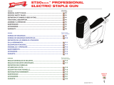
How to Open Tape Holder and Bobbin Case
Put your fingers on UP part (A) (B), then open the cover. (Fig. 3)
*
Comment ouvrir le boîtier à bande et le boîtier de la
bobine
Appuyer les doigts sur la partie UP (A) (B), puis ouvrir le couvercle. (Fig. 3)
*
Cómo abrir el contenedor de cinta y la caja de bobina
Ponga los dedos en la parte SUPERIOR (A) (B) y abra la tapa. (Fig. 3)
HOW TO USE / MÉTHODE D'UTILISATION /
MODO DE USO
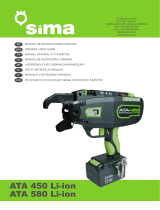
How to Load Staples
1 Hold the body with one hand, push the lever down and pull the lever towards
your direction. (Fig. 1)
* The pusher cannot be removed from the main body.
2 While holding the tool in one hand, insert staples into the magazine so that
staples' legs point upward, and then set them in the pusher unit by sliding
lever. You can load 604C type or 604E type. (Fig. 2)
*
Comment charger les agrafes
1 Tenir le corps de la ficeleuse d'une main, pousser le levier vers le bas et le
tirer vers vous. (Fig. 1)
* Le poussoir ne peut pas être ôté du corps principal.
2 Tout en tenant l'outil d'une main, insérer les agrafes dans le magasin afin que
les pattes soient tournées vers le haut, puis les insérer dans le poussoir à
l'aide du levier coulissant. Il est possible de charger des agrafes du type 604C
ou du type 604E. (Fig. 2)
*
Cómo cargar las grapas
1 Mientras sujeta la herramienta con una mano, empuje la palanca hacia abajo
y tire de ella hacia usted. (Fig. 1)
* El empujador no puede extraerse de la herramienta.
2 Mientras sujeta la herramienta con una mano, introduzca las grapas en el
cargador con las puntas hacia arriba y, a continuación, colóquelas en el
empujador deslizando la palanca. Se pueden cargar grapas del modelo 604C
o 604E. (Fig. 2)
CAUTION
●Be sure to USE the specified tape.
●NEVER apply your fingers near the front end of the magazine unit because
there is a serrated blade and the staple ejection port nearby.
●Do not insert a branch near the cutting blade. Doing so may damage the
cutting blade or peripheral parts.
*
ATTENTION
●S'assurer d'UTILISER la bande indiquée.
●Ne JAMAIS appliquer les doigts à proximité de la partie avant du magasin car
elle présente un orifice dentelé d'éjection de la lame et d'agrafes à proximité.
●Ne pas insérer de branche à proximité de la lame de coupe. Cela pourrait
endommager la lame de coupe ou des pièces périphériques.
*
PRECAUCIÓN
●Asegúrese de UTILIZAR la cinta especificada.
●NUNCA coloque los dedos cerca del extremo delantero del cargador, ya
que aquí se encuentran una cuchilla dentada y el orificio de expulsión de las
grapas.
●No introduzca un palo cerca de la cuchilla, ya que al hacerlo podría dañar la
cuchilla o los componentes circundantes.
PARTS LIST / LISTE DES PIÈCES /
LISTA DE COMPONENTES
Index No. Parts Code No. Description
1 HT11672 B CASE S
2 FF31714 STRAIGHT PIN 1714
3 FF31712 STRAIGHT PIN 1712
4 KK33402 TORSION SPRING 3402
5 KK29130 COMPRESSION SPRING 9130
6 HT11670 LOCK PLATE S
7 HT11627 A CASE
8 CC43107 NAT M4(3)
9 AA05719 +PH TAP SCREW 3×8 (P)
10 HT11632 CLINCHER
11 HT11622 TAPE CATCH
12 HT11671 TAPE PLATE S
13 AA25537 SCREW BIND M4×6
14 HT11618 CLINCHER ARM
15 AA05716 SCREW BIND 4×6 (S-TIGHT)
16 HT11619 ARM SUPPORT
17 HT11637 B HANDLE
18 FF31713 STRAIGHT PIN 1713
19 HT11638 GRIP
20 KK13390 EXTENSION SPRING 3390
21 HT70061 MAGAZINE UNIT
22 FF31716 STRAIGHT PIN 1716
23 HT11611 PUSHER
24 HT11610 SPRING GUIDE ROD
25 KK29131 COMPRESSION SPRING 9131
26 HT11609 STAPLE COVER
27 PRODUCT CUTTER
28 KK34099 TORSION SPRING 4099
29 HT70070 TAPE GUIDE S UNIT
30 FF41740 STEP PIN 1740
31 HT11596 TAPE GUIDE SUPPORT
32 HT11673 TAPE GUIDE BASE S
33 FF31711 STRAIGHT PIN 1711
34 KK83018 CONICAL SPRING 3018
35 JJ10103 E-RING 3.2
36 HT11615 ROLLER
37 FF31643 STRAIGHT PIN 1643
38 FF31644 STRAIGHT PIN 1644
39 HT11592 DRIVER
40 HT11591 A HANDLE
41 HT11603 TAPE SPRING
SPECIFICATIONS / SPÉCIFICATIONS /
ESPECIFICACIONES
Name /
Nom /
Nombre
HT-R1 HT-R2
Dimensions /
Dimensions /
Dimensiones
148mm H × 353mm L ×
35mm W
161mm H × 392mm L ×
35mm W
Staples Used /
Agrafes utilisées /
Grapas utilizadas
MAX STAPLES 604C-L (4,800 pcs)
MAX STAPLES 604E-L (4,800 pcs)
Number of Staples
Loaded /
Nombre d'agrafes
chargées /
Número de grapas
cargadas
MAX STAPLES 604C-L 200 pcs / stick
MAX STAPLES 604E-L 172 pcs / stick
Tape Used /
Bande utilisée /
Cinta utilizada
MAX TAPE-10, 0.1mm T × 11mm
W × 40m L (White/Blanche/Blanco)
MAX TAPE-15, 0.15mm T × 11mm
W × 26m L (Blue/Bleue/Azul)
MAX TAPE-25, 0.25mm T × 11mm
W × 16m L (Red/Rouge/Rojo)
MAX TAPE-215, 0.15mm T ×
12mm W × 55m L (White/Blanche/
Blanco)
MAX TAPE-225, 0.25mm T ×
12mm W × 33m L (Blue/Bleue/
Azul)
Weight /
Poids /
Peso
420 grams 445 grams
Bundling Limit /
Limite de liage /
Límite de atadura
Maximum 45mmφ × parallel
20mmφ
Maximum 45mmφ × parallel
20mmφ
Blade /
Lame /
Cuchilla
MAX Tapener HT-R Serrated
Blades
MAX Tapener HT-R Serrated
Blades
Staple’s Full-Scale
Figure /
Illustration des agrafes
à l'échelle 1 /
Imagen de la grapa a
escala completa
(mm)
604C-L
0.3 0.56
4
604E-L
0.3 0.66
4
WARNING:
BEFORE USING THIS TOOL, STUDY THIS MANUAL TO ENSURE
SAFETY WARNING AND INSTRUCTIONS.
KEEP THESE INSTRUCTIONS WITH THE TOOL FOR FUTURE
REFERENCE.
AVERTISSEMENT :
AVANT D'UTILISER CET OUTIL, ÉTUDIEZ CE MANUEL AFIN DE
PRENDRE CONNAISSANCE DES AVERTISSEMENTS ET DES
INSTRUCTIONS.
CONSERVEZ CES INSTRUCTIONS AVEC L'OUTIL POUR TOUTE
CONSULTATION ULTÉRIEURE.
ADVERTENCIA:
ANTES DE USAR ESTA HERRAMIENTA, LEA DETENIDAMENTE
ESTAS INSTRUCCIONES Y ASEGÚRESE DE RESPETAR LAS
ADVERTENCIAS DE SEGURIDAD.
CONSERVE ESTAS INSTRUCCIONES CON LA HERRAMIENTA
PARA FUTURAS CONSULTAS.
HT-R1, HT-R2
INSTRUCTION MANUAL
MANUEL D'INSTRUCTIONS
INSTRUCCIONES DE USO
HT-R1 Exploded View
9
13
1
7
8
2
3
4
5
6
8
8
10
3
12
15
15
15
13
16
16
11
14
18
9
17
19
20
21
22
53
53
23
24
25
26
35
34
36
36
35
35
37
38
35
41
48
51
50
55
56
Parts marked are
included in
the A HANDLE ASSY
27
29
30
31
28
32
33
39
40
15
15
Index No. Parts Code No. Description
48 AA05715 SCREW BIND 4×16 (P)
50 HT70064 TAPE HOLDER ASSY
51 HT70065 BOBBIN CASE ASSY (HT-R)
51 HT70067 BOBBIN CASE ASSY (HT-R2)
53 GN12070 RUBBER WASHER 1.7×6×2
55 HT70068 TAPE CATCH ASSY
56 HT70071 A HANDLE ASSY
HT11646
171108-00/02
Push up
Pull
Pusher
Tape Lid
Lever
Fig. 1
Tape Holder
(A)
Bobbin Case
(B)
Fig. 3
Staple
Fig. 2
Tape
5cm
The edge of the Tape Holder
Fig. 4
How to Load the Tape
1 Open the tape holder and the bobbin case. And insert the tape roll into the
bobbin case. (Fig. 4)
2 Pull tape into the tape holder and make sure approximately 5 cm of tape
hangs out of the edge of the tape holder.
3 Load the tape through the two guides of the tape guide. (Fig. 5, 6)
*
Comment charger la bande
1 Ouvrir le boîtier à bandes et le boîtier à bobine. Et insérer un rouleau de
bande dans le boîtier à bobine. (Fig. 4)
2 Tirer la bande dans le boîtier à bande et s'assurer qu'environ 5 cm de bande
dépassent du bord du boîtier à bande.
3 Charger la bande à travers les deux guides-bandes. (Fig. 5, 6)
*
Cómo cargar la cinta
1 Abra el contenedor de cinta y la caja de bobina, e introduzca el rollo de cinta
en la caja de bobina. (Fig. 4)
2 Tire de la cinta para introducirla en el contenedor de cinta y asegúrese de que
queden aproximadamente 5 cm de cinta colgando del borde del contenedor
de cinta.
3 Encaje la cinta a lo largo de los dos extremos de la guía. (Fig. 5, 6)
Tape Holder
Bobbin Case
Fig. 5
Tape Guide
Tooth
Fig. 6

AFTER USE
In order to maintain proper performance, apply oil to the specified locations after
each use. (Fig. 19)
*
APRÈS UTILISATION
Pour préserver les performances, appliquer de l'huile aux endroits indiqués
après chaque utilisation. (Fig. 19)
*
DESPUÉS DEL USO
Para mantener un funcionamiento óptimo de la herramienta, aplique aceite en
los lugares especificados después de cada uso. (Fig. 19)
How to Remove Jammed Staples
While the pusher unit is open, remove any loaded staples, and then remove the
stuck staple with a small screwdriver (1). (Fig. 18)
*
Comment retirer des agrafes coincées
Lorsque le pressoir est ouvert, retirez les agrafes chargées puis l'agrafe coincée
à l'aide d'un tournevis (1). (Fig. 18)
*
Cómo extraer grapas atascadas
Abra el empujador, extraiga todas las grapas cargadas y, a continuación,
extraiga la grapa atascada con la ayuda de un destornillador pequeño (1).
(Fig. 18)
WARNING:
●Keepyourfingersawayfromthecuttingblade.
AVERTISSEMENT :
●Tenirlesdoigtàl'écartdelalamededécoupe.
ADVERTENCIA:
●Mantengalosdedosalejadosdelacuchilla.
Confirmation
● Confirm that the round hole of the cutting blade is completely hidden.
(Fig. 17)
*
Confirmation
● Vérifier que l'orifice circulaire de la lame de découpe est complètement
masqué. (Fig. 17)
*
Confirmación
● Confirme que el orificio redondo de la cuchilla esté completamente oculto.
(Fig. 17)
How to Change Blade /
Méthode de rechange de la lame /
Cómo cambiar la cuchilla
Preparation
1 Do not remove the cap from the blade. (Fig. 11)
2 Remove the tape and staples.
3 Open the arm and tape holder cover. (Fig. 12)
4 As shown in Fig. 13, hold the main body with one hand. (Fig. 13)
*
Préparation
1 Ne pas retirer le capuchon de la lame. (Fig. 11)
2 Retirer la bande et les agrafes.
3 Ouvrir le bras et le couvercle du boîtier à bande. (Fig. 12)
4 Tenir le corps principal d'une main, comme illustré sur la figure 13. (Fig. 13)
*
Preparación
1 No quite el capuchón de la cuchilla. (Fig. 11)
2 Extraiga la cinta y las grapas.
3 Abra el brazo y la tapa del contenedor de cinta. (Fig. 12)
4 Tal como se indica en la Fig. 13, sujete la herramienta con una mano.
(Fig. 13)
Change the Blade
1 Press the button and pull out the old cutting blade.
2 Press the button and push the cutting blade cap deep enough so that three
triangles are aligned (correct position shown in the figure). (Fig.15)
● Release the button and pull off the cutting blade cap. (Fig.16)
*
Changer la lame
1 Appuyer sur le bouton et tirer l'ancienne lame de découpe vers l'extérieur.
2 Appuyer sur le bouton et pousser le capuchon de la lame de découpe de
manière suffisamment profonde afin que les trois triangles soient alignés
(position correcte indiquée sur la figure.) (Fig.15)
● Relâcher le bouton et retirer le capuchon de la lame de découpe. (Fig.16)
*
Cambiar la cuchilla
1 Presione el botón y extraiga la cuchilla vieja.
2 Presione el botón y empuje firmemente el capuchón de la cuchilla hasta
que los tres triángulos queden alineados (en la figura se indica la posición
correcta). (Fig.15)
● Suelte el botón y quite el capuchón de la cuchilla. (Fig.16)
How to Bind Objects
1 Press the tape against the object until it is positioned inside the tapener.
(Fig. 9)
2 Then, fully squeeze the grip with the tape positioned centrally, and the object
will be bound by both the tape and staple; simultaneously, the tape is cut off.
(Fig. 10)
*
Comment lier les objets
1 Presser la bande contre l'objet jusqu'à ce que ce dernier se trouve à l'intérieur
de la ficeleuse. (Fig. 9)
2 Puis, la bande se trouvant au centre, presser la poignée à fond et l'objet
est lié par la bande qui est agrafée ; la bande est coupée simultanément.
(Fig. 10)
*
Cómo atar objetos
1 Presione la cinta contra el objeto hasta que éste quede colocado dentro de la
atadora. (Fig. 9)
2 A continuación, apriete fuertemente el mango con la cinta colocada de
forma centrada. El objeto quedará atado por la cinta y por la grapa y,
simultáneamente, la cinta se cortará. (Fig. 10)
Cómo arrastrar la cinta
1 Apriete el mango de forma que el dispositivo de agarre de la cinta agarre
firmemente el extremo de la cinta. (Fig. 7)
2 Suelte el mango para que la cinta sea arrastrada por el dispositivo. (Fig. 8)
3 Si el dispositivo de agarre de la cinta no agarra el extremo de la cinta al
apretar el mango, apriete el mango con más fuerza varias veces más, y el
dispositivo de agarre de la cinta volverá a su posición normal. (Esto no es un
defecto del dispositivo.)
Nota: Esto solo debe hacerse cuando el dispositivo de agarre de la cinta no
agarre el extremo de la cinta.
Tape Catch
Clincher Arm
Grip
Fig. 7 Fig. 9Fig. 8
Grip
Fig. 10
Flat-head
Screwdriver
Exit Hole
Fig. 18
Fig. 19
Cap
Blade
Fig. 11
Arm
Tape Holder Cover
Fig. 12
Fig. 13
Button
Fig. 14
Align the triangles. / Aligner les triangles. /
Alinee los triángulos.
Red parts
Fig. 15
Button
Fig. 16
OK
Invisible /
Invisible /
No visible
Fig. 17
NG
Visible /
Visible /
Visible
How to Pull Out Tape
1 Squeeze the handle so that the tape catch will catch the tape end deep
enough. (Fig. 7)
2 Release the handle as explained. The tape will pull out. (Fig. 8)
3 If the tape catch unit does not catch the tape end when you squeeze the
handle, please squeeze the handle harder several more times, and the tape
catch will return to its normal position. (This is not a trouble with the tapener.)
Note: This should be done only when the tape catch does not catch the tape
end.
*
Comment dégager la bande
1 Presser le manche de façon que l'accrocheur de bande accroche le bout de la
bande avec une profondeur suffisante. (Fig. 7)
2 Relâcher le manche comme expliqué. La bande est tirée vers l'extérieur.
(Fig. 8)
3 Si l'accrocheur de bande n'accroche pas le bout de la bande quand vous
pressez le manche, le presser à plusieurs reprises, et l'accrocheur revient en
position normale. (Cela n'est pas un dysfonctionnement de la ficeleuse.)
Remarque: ne procéder ainsi que si l'accrocheur de bande n'accroche pas le
bout de la bande.
*
Transcripción de documentos
SPECIFICATIONS / SPÉCIFICATIONS / ESPECIFICACIONES HT-R1, HT-R2 INSTRUCTION MANUAL MANUEL D'INSTRUCTIONS INSTRUCCIONES DE USO HT11646 171108-00/02 WARNING: BEFORE USING THIS TOOL, STUDY THIS MANUAL TO ENSURE SAFETY WARNING AND INSTRUCTIONS. KEEP THESE INSTRUCTIONS WITH THE TOOL FOR FUTURE REFERENCE. AVERTISSEMENT : AVANT D'UTILISER CET OUTIL, ÉTUDIEZ CE MANUEL AFIN DE PRENDRE CONNAISSANCE DES AVERTISSEMENTS ET DES INSTRUCTIONS. CONSERVEZ CES INSTRUCTIONS AVEC L'OUTIL POUR TOUTE CONSULTATION ULTÉRIEURE. ADVERTENCIA: ANTES DE USAR ESTA HERRAMIENTA, LEA DETENIDAMENTE ESTAS INSTRUCCIONES Y ASEGÚRESE DE RESPETAR LAS ADVERTENCIAS DE SEGURIDAD. CONSERVE ESTAS INSTRUCCIONES CON LA HERRAMIENTA PARA FUTURAS CONSULTAS. Name / Nom / Nombre Dimensions / Dimensions / Dimensiones Staples Used / Agrafes utilisées / Grapas utilizadas Number of Staples Loaded / Nombre d'agrafes chargées / Número de grapas cargadas Tape Used / Bande utilisée / Cinta utilizada Weight / Poids / Peso Bundling Limit / Limite de liage / Límite de atadura Blade / Lame / Cuchilla Staple’s Full-Scale Figure / Illustration des agrafes à l'échelle 1 / Imagen de la grapa a escala completa (mm) PARTS LIST / LISTE DES PIÈCES / LISTA DE COMPONENTES HT-R1 HT-R2 148mm H × 353mm L × 35mm W 161mm H × 392mm L × 35mm W MAX STAPLES 604C-L (4,800 pcs) MAX STAPLES 604E-L (4,800 pcs) MAX STAPLES 604C-L 200 pcs / stick MAX STAPLES 604E-L 172 pcs / stick MAX TAPE-10, 0.1mm T × 11mm W × 40m L (White/Blanche/Blanco) MAX TAPE-15, 0.15mm T × 11mm W × 26m L (Blue/Bleue/Azul) MAX TAPE-25, 0.25mm T × 11mm W × 16m L (Red/Rouge/Rojo) MAX TAPE-215, 0.15mm T × 12mm W × 55m L (White/Blanche/ Blanco) MAX TAPE-225, 0.25mm T × 12mm W × 33m L (Blue/Bleue/ Azul) 420 grams 445 grams Maximum 45mmφ × parallel 20mmφ Maximum 45mmφ × parallel 20mmφ MAX Tapener HT-R Serrated Blades MAX Tapener HT-R Serrated Blades 604C-L 604E-L 4 0.3 6 0.5 4 0.3 6 0.6 Index No. Parts Code No. 1 HT11672 2 FF31714 3 FF31712 4 KK33402 5 KK29130 6 HT11670 7 HT11627 8 CC43107 9 AA05719 10 HT11632 11 HT11622 12 HT11671 13 AA25537 14 HT11618 15 AA05716 16 HT11619 17 HT11637 18 FF31713 19 HT11638 20 KK13390 21 HT70061 22 FF31716 23 HT11611 24 HT11610 25 KK29131 26 HT11609 27 PRODUCT 28 KK34099 29 HT70070 30 FF41740 31 HT11596 32 HT11673 33 FF31711 34 KK83018 35 JJ10103 36 HT11615 37 FF31643 38 FF31644 39 HT11592 40 HT11591 41 HT11603 Index No. Parts Code No. 48 AA05715 50 HT70064 51 HT70065 51 HT70067 53 GN12070 55 HT70068 56 HT70071 Description B CASE S STRAIGHT PIN 1714 STRAIGHT PIN 1712 TORSION SPRING 3402 COMPRESSION SPRING 9130 LOCK PLATE S A CASE NAT M4(3) +PH TAP SCREW 3×8 (P) CLINCHER TAPE CATCH TAPE PLATE S SCREW BIND M4×6 CLINCHER ARM SCREW BIND 4×6 (S-TIGHT) ARM SUPPORT B HANDLE STRAIGHT PIN 1713 GRIP EXTENSION SPRING 3390 MAGAZINE UNIT STRAIGHT PIN 1716 PUSHER SPRING GUIDE ROD COMPRESSION SPRING 9131 STAPLE COVER CUTTER TORSION SPRING 4099 TAPE GUIDE S UNIT STEP PIN 1740 TAPE GUIDE SUPPORT TAPE GUIDE BASE S STRAIGHT PIN 1711 CONICAL SPRING 3018 E-RING 3.2 ROLLER STRAIGHT PIN 1643 STRAIGHT PIN 1644 DRIVER A HANDLE TAPE SPRING Description SCREW BIND 4×16 (P) TAPE HOLDER ASSY BOBBIN CASE ASSY (HT-R) BOBBIN CASE ASSY (HT-R2) RUBBER WASHER 1.7×6×2 TAPE CATCH ASSY A HANDLE ASSY HT-R1 Exploded View 55 1 3 4 8 9 8 5 7 6 2 8 19 11 3 12 10 15 17 16 13 15 9 14 15 Parts marked are included in the A HANDLE ASSY 56 13 28 31 39 30 25 24 53 23 22 32 34 35 29 26 16 20 21 27 18 51 53 35 36 33 38 40 35 37 36 35 15 15 41 48 50 2017/11/07 HOW TO USE / MÉTHODE D'UTILISATION / MODO DE USO How to Load Staples 1 Hold the body with one hand, push the lever down and pull the lever towards your direction. (Fig. 1) * The pusher cannot be removed from the main body. 2 While holding the tool in one hand, insert staples into the magazine so that staples' legs point upward, and then set them in the pusher unit by sliding lever. You can load 604C type or 604E type. (Fig. 2) * Comment charger les agrafes 1 Tenir le corps de la ficeleuse d'une main, pousser le levier vers le bas et le tirer vers vous. (Fig. 1) * Le poussoir ne peut pas être ôté du corps principal. 2 Tout en tenant l'outil d'une main, insérer les agrafes dans le magasin afin que les pattes soient tournées vers le haut, puis les insérer dans le poussoir à l'aide du levier coulissant. Il est possible de charger des agrafes du type 604C ou du type 604E. (Fig. 2) * Fig. 1 Fig. 2 ① Push up ② Pull Pusher Lever Staple Tape Lid Cómo cargar las grapas 1 Mientras sujeta la herramienta con una mano, empuje la palanca hacia abajo y tire de ella hacia usted. (Fig. 1) * El empujador no puede extraerse de la herramienta. 2 Mientras sujeta la herramienta con una mano, introduzca las grapas en el cargador con las puntas hacia arriba y, a continuación, colóquelas en el empujador deslizando la palanca. Se pueden cargar grapas del modelo 604C o 604E. (Fig. 2) How to Open Tape Holder and Bobbin Case Put your fingers on UP part (A) (B), then open the cover. (Fig. 3) * Comment ouvrir le boîtier à bande et le boîtier de la bobine Appuyer les doigts sur la partie UP (A) (B), puis ouvrir le couvercle. (Fig. 3) * Cómo abrir el contenedor de cinta y la caja de bobina Ponga los dedos en la parte SUPERIOR (A) (B) y abra la tapa. (Fig. 3) CAUTION ●Be sure to USE the specified tape. ●NEVER apply your fingers near the front end of the magazine unit because there is a serrated blade and the staple ejection port nearby. ●Do not insert a branch near the cutting blade. Doing so may damage the cutting blade or peripheral parts. * PRECAUCIÓN ●Asegúrese de UTILIZAR la cinta especificada. ●NUNCA coloque los dedos cerca del extremo delantero del cargador, ya que aquí se encuentran una cuchilla dentada y el orificio de expulsión de las grapas. ●No introduzca un palo cerca de la cuchilla, ya que al hacerlo podría dañar la cuchilla o los componentes circundantes. 1 Open the tape holder and the bobbin case. And insert the tape roll into the bobbin case. (Fig. 4) 2 Pull tape into the tape holder and make sure approximately 5 cm of tape hangs out of the edge of the tape holder. 3 Load the tape through the two guides of the tape guide. (Fig. 5, 6) * Comment charger la bande 1 Ouvrir le boîtier à bandes et le boîtier à bobine. Et insérer un rouleau de bande dans le boîtier à bobine. (Fig. 4) 2 Tirer la bande dans le boîtier à bande et s'assurer qu'environ 5 cm de bande dépassent du bord du boîtier à bande. 3 Charger la bande à travers les deux guides-bandes. (Fig. 5, 6) * Cómo cargar la cinta 1 Abra el contenedor de cinta y la caja de bobina, e introduzca el rollo de cinta en la caja de bobina. (Fig. 4) 2 Tire de la cinta para introducirla en el contenedor de cinta y asegúrese de que queden aproximadamente 5 cm de cinta colgando del borde del contenedor de cinta. 3 Encaje la cinta a lo largo de los dos extremos de la guía. (Fig. 5, 6) ATTENTION ●S'assurer d'UTILISER la bande indiquée. ●Ne JAMAIS appliquer les doigts à proximité de la partie avant du magasin car elle présente un orifice dentelé d'éjection de la lame et d'agrafes à proximité. ●Ne pas insérer de branche à proximité de la lame de coupe. Cela pourrait endommager la lame de coupe ou des pièces périphériques. * How to Load the Tape Fig. 3 Fig. 4 Tape Holder The edge of the Tape Holder (A) 5cm Bobbin Case Fig. 5 (B) Fig. 6 Tape Holder Tape Bobbin Case Tape Guide Tooth How to Pull Out Tape 1 Squeeze the handle so that the tape catch will catch the tape end deep enough. (Fig. 7) 2 Release the handle as explained. The tape will pull out. (Fig. 8) 3 If the tape catch unit does not catch the tape end when you squeeze the handle, please squeeze the handle harder several more times, and the tape catch will return to its normal position. (This is not a trouble with the tapener.) Note: This should be done only when the tape catch does not catch the tape end. * Cómo arrastrar la cinta 1 Apriete el mango de forma que el dispositivo de agarre de la cinta agarre firmemente el extremo de la cinta. (Fig. 7) 2 Suelte el mango para que la cinta sea arrastrada por el dispositivo. (Fig. 8) 3 Si el dispositivo de agarre de la cinta no agarra el extremo de la cinta al apretar el mango, apriete el mango con más fuerza varias veces más, y el dispositivo de agarre de la cinta volverá a su posición normal. (Esto no es un defecto del dispositivo.) Nota: Esto solo debe hacerse cuando el dispositivo de agarre de la cinta no agarre el extremo de la cinta. Comment dégager la bande 1 Presser le manche de façon que l'accrocheur de bande accroche le bout de la bande avec une profondeur suffisante. (Fig. 7) 2 Relâcher le manche comme expliqué. La bande est tirée vers l'extérieur. (Fig. 8) 3 Si l'accrocheur de bande n'accroche pas le bout de la bande quand vous pressez le manche, le presser à plusieurs reprises, et l'accrocheur revient en position normale. (Cela n'est pas un dysfonctionnement de la ficeleuse.) Remarque: ne procéder ainsi que si l'accrocheur de bande n'accroche pas le bout de la bande. How to Bind Objects 1 Press the tape against the object until it is positioned inside the tapener. (Fig. 9) 2 Then, fully squeeze the grip with the tape positioned centrally, and the object will be bound by both the tape and staple; simultaneously, the tape is cut off. (Fig. 10) * Comment lier les objets 1 Presser la bande contre l'objet jusqu'à ce que ce dernier se trouve à l'intérieur de la ficeleuse. (Fig. 9) 2 Puis, la bande se trouvant au centre, presser la poignée à fond et l'objet est lié par la bande qui est agrafée ; la bande est coupée simultanément. (Fig. 10) * Cómo atar objetos 1 Presione la cinta contra el objeto hasta que éste quede colocado dentro de la atadora. (Fig. 9) 2 A continuación, apriete fuertemente el mango con la cinta colocada de forma centrada. El objeto quedará atado por la cinta y por la grapa y, simultáneamente, la cinta se cortará. (Fig. 10) * Fig. 7 Fig. 8 Fig. 9 Fig. 10 How to Change Blade / Méthode de rechange de la lame / Cómo cambiar la cuchilla Preparation 1 2 3 4 Do not remove the cap from the blade. (Fig. 11) Remove the tape and staples. Open the arm and tape holder cover. (Fig. 12) As shown in Fig. 13, hold the main body with one hand. (Fig. 13) * Préparation 1 2 3 4 Ne pas retirer le capuchon de la lame. (Fig. 11) Retirer la bande et les agrafes. Ouvrir le bras et le couvercle du boîtier à bande. (Fig. 12) Tenir le corps principal d'une main, comme illustré sur la figure 13. (Fig. 13) * Preparación 1 2 3 4 No quite el capuchón de la cuchilla. (Fig. 11) Extraiga la cinta y las grapas. Abra el brazo y la tapa del contenedor de cinta. (Fig. 12) Tal como se indica en la Fig. 13, sujete la herramienta con una mano. (Fig. 13) Fig. 11 Fig. 12 Cap Clincher Arm Fig. 13 Arm ❸ ❶ ❷ Grip Grip Tape Catch Change the Blade 1 Press the button and pull out the old cutting blade. 2 Press the button and push the cutting blade cap deep enough so that three triangles are aligned (correct position shown in the figure). (Fig.15) ● Release the button and pull off the cutting blade cap. (Fig.16) * How to Remove Jammed Staples WARNING: While the pusher unit is open, remove any loaded staples, and then remove the stuck staple with a small screwdriver (1). (Fig. 18) * ● Keep your fingers away from the cutting blade. AVERTISSEMENT : Comment retirer des agrafes coincées ● Tenir les doigt à l'écart de la lame de découpe. Lorsque le pressoir est ouvert, retirez les agrafes chargées puis l'agrafe coincée à l'aide d'un tournevis (1). (Fig. 18) * ADVERTENCIA: Changer la lame 1 Appuyer sur le bouton et tirer l'ancienne lame de découpe vers l'extérieur. 2 Appuyer sur le bouton et pousser le capuchon de la lame de découpe de manière suffisamment profonde afin que les trois triangles soient alignés (position correcte indiquée sur la figure.) (Fig.15) ● Relâcher le bouton et retirer le capuchon de la lame de découpe. (Fig.16) Cómo extraer grapas atascadas ● Mantenga los dedos alejados de la cuchilla. Abra el empujador, extraiga todas las grapas cargadas y, a continuación, extraiga la grapa atascada con la ayuda de un destornillador pequeño (1). (Fig. 18) Cambiar la cuchilla 1 Presione el botón y extraiga la cuchilla vieja. 2 Presione el botón y empuje firmemente el capuchón de la cuchilla hasta que los tres triángulos queden alineados (en la figura se indica la posición correcta). (Fig.15) ● Suelte el botón y quite el capuchón de la cuchilla. (Fig.16) Fig. 16 * Fig. 17 Fig. 18 OK Button Invisible / Invisible / No visible NG Visible / Visible / Visible Red parts Flat-head Screwdriver Align the triangles. / Aligner les triangles. / Alinee los triángulos. Pour préserver les performances, appliquer de l'huile aux endroits indiqués après chaque utilisation. (Fig. 19) * DESPUÉS DEL USO Para mantener un funcionamiento óptimo de la herramienta, aplique aceite en los lugares especificados después de cada uso. (Fig. 19) Fig. 19 ● Vérifier que l'orifice circulaire de la lame de découpe est complètement masqué. (Fig. 17) ● Confirme que el orificio redondo de la cuchilla esté completamente oculto. (Fig. 17) Button APRÈS UTILISATION * Confirmación Fig. 15 In order to maintain proper performance, apply oil to the specified locations after each use. (Fig. 19) * Confirmation Confirmation Exit Hole Tape Holder Cover AFTER USE ● Confirm that the round hole of the cutting blade is completely hidden. (Fig. 17) * Fig. 14 Blade-
 1
1
-
 2
2


en otros idiomas
- français: Max HT-R1 Le manuel du propriétaire
- English: Max HT-R1 Owner's manual
Otros documentos
-
Anova ATB2502 El manual del propietario
-
 SIMA S.A. ATA 450 Li Manual de usuario
-
DeWalt DCN701BW230C Manual de usuario
-
DeWalt DCFS950 Manual de usuario
-
-
-
 Arrow Fastener ET50RED Manual de usuario
-
Waring 7155-21 Manual de usuario
-
Ryobi YG125CS Guía del usuario
-
Hikoki N5024A2 Manual de usuario

