GE Caliber Guía del usuario
- Tipo
- Guía del usuario

CALIBER SPECIFICATION GUIDE
Caliber Specification Guide / Caliber Specification Guide
31-5000523 Rev. 0 02-21 GEA

231-5000523 Rev. 0

31-5000523 Rev. 0 3
UNIT DIMENSIONS ..............................................................................4
CLEARANCES ..................................................................................5
SYSTEM .......................................................................................6
Part 1: General ...............................................................................6
Part 2: Performance and Operating Range .........................................................6
Part 3: Installation Requirements ................................................................8
Part 4: Electrical Requirements ..................................................................8
OUTDOOR UNIT .................................................................................9
Part 1: General ...............................................................................9
Part 2: Installation .............................................................................9
Part 3: Components ...........................................................................9
WALL MOUNT INDOOR UNIT .....................................................................10
Part 1: General ..............................................................................10
Part 2: Installation Requirements ................................................................10
Part 3: Electrical Requirements .................................................................11
Part 4: Components ..........................................................................11
CONTROLS AND ACCESSORIES .................................................................. 12
Part 1: Primary Remote Control .................................................................12
Part 2: Wired Controllers ......................................................................12
Part 3: WiFi Adapter ..........................................................................13
Part 4: WK-B Interface Kit .....................................................................13
LIMITED WARRANTY ........................................................................... 15
Table of Contents

431-5000523 Rev. 0
ASH109CRAWA / ASYW09CRAWA
ASH112CRAWA / ASYW12CRAWA
ASH118CRDWA / ASYW18CRDWA
ASH124CRDWA / ASYW24CRDWA
30 3/4 (780)
21 1/4 (540)
9 5/8 (245)
34 (964)
7 7/8 (200)
11 3/8 (290)
35 (890)
271/2 (697)
13 7/8 (353)
39 5/8 (1008)
8 7/8 (225)
12 1/2 (218)
36 1/4 (920)
30 (762)
15 1/8 (385
)
44 1/4 (1125)
9 1/2 (240)
113 3/4 (335)
Unit Dimensions

31-5000523 Rev. 0 5
Selection of installation location of outdoor
unit:
MINIMUM CLEARANCES
(Appearance may vary)
Mounting the outdoor unit:
The distance between
the indoor unit and the
or should be more
than 6 feet.
more than 4in.
more than 4in.
more than 4in.
more than 4in. more than 6in.
more than 24in.
more than 6in.
Attention must be paid to
the pitch of drain hose
Z
1 2
Refer to Submittal Document for unit dimensions.
Mounting feet positions for the outdoor unit.
Securely attach the unit to a mounting pad
or brackets with 7/16" (10mm) bolts.
Use the mounting feet pads or vibration mats
where noise transmission may be a concern.
Follow local code when mounting the unit
strong winds or earthquakes.
This picture is for reference only, as your product may look different. Read your manual before installation. Explain
the operation of the unit to the user according to this manual.
Piping Exit Options
Rear left
Left Rear
right
Right
Below
System Clearances

631-5000523 Rev. 0
Part 1: General
1.1 Description
A. The GEA Caliber heat pump air conditioner shall be a variable capacity, mini-split type system comprised
of a single outdoor and a single wall-mounted indoor unit.
1.2 Toxicity
A. The heat pump system shall participate in RoHS compliance and listed in the directory.
Part 2: Performance and Operating Range
2.1 Operating Range
A. The heat pump shall provide cooling temperature range of 14°~115°F (-10°C~46°C) with a wind baffle
installed.
B. The heat pump shall provide cooling temperature range of 23°F~115°F (-5~46°C) without a wind baffle
installed.
C. The heat pump system shall be capable of providing greater than 70% capacity at 17°F (-8°C) outdoor
ambient temperature.
D. The ASH109CRAWA and ASH112CRAWA heat pump models shall operate normally with voltages
between 104~127V.
E. The ASH118CRDWA and ASH124CRDWA heat pump models shall operate normally with voltages
between 187~253V.
2.2 Performance
The system shall perform within the specified operating window found on the following table.
A. Cooling performance rating shall be verified following AHRI 210/240 standards of 80°F DB/67°F WB
(27°/19°C) indoor temperature and 95°F DB/75°F WB (35°/24°C) outdoor temperature.
B. Heating performance rating shall be verified following AHRI 210/240 standards of 70°F DB/60°F WB
(21°/16°C) indoor temperature and 47°F DB/43°F WB (8°/6°C) outdoor temperature.
2.3 Performance Related to Pipe Length
Pipe lengths beyond 25 feet will affect the rated performance of the installed system. See the below table.
9K and 12K Models
Pipe Length (ft) 25 33 50 66
Capacity correction factor (cooling) 100% 98% 96% 94%
Capacity correction factor (heating) 100% 98% 97% 95%
18K and 24K
Models
Pipe Length (ft) 25 33 50 66 82
Capacity correction factor (cooling) 100% 99% 97% 95% 93%
Capacity correction factor (heating) 100% 99% 98% 95% 94%
System

31-5000523 Rev. 0 7
Model Name System 09CR 12CR 18CR 24CR
Outdoor ASH109CRAWA ASH112CRAWA ASH118CRDWA ASH124CRDWA
Indoor ASYW09CRAWA ASYW12CRAWA ASYW18CRDWA ASYW24CRDWA
Cooling Rated Capacity Btu/hr 9,000 12,000 18,000 24,000
Capacity Range Btu/hr 3,800~12,000 4,100~12,500 5,000~19,000 6,500~26,000
Rated Power Input W 810 1,200 1,650 2,150
SEER 16 16 16 16
EER 11.0 11.0 10.0 10.0
Moisture Removal gal./hr. 0.31 0.42 0.52 0.73
Heating Rated Heating Capacity 47°F
Btu/hr
10,000 12,000 19,000 26,000
Heating Capacity Range Btu/hr 4,100~12,000 4,500~16,000 5,400~22,000 6,800~28,000
Rated Power Input W 850 1,000 1,700 2,400
HSPF 9.0 9.0 9.0 9.0
Rated Heating Capacity 17°F
Btu/hr
5,600 7,800 11,200 16,600
Max. Heating Cap. 17°F (-8°C)
Btu/hr
8,200 10,000 15,500 19,300
Heating Cap. 5°F (-15°C)
Btu/hr
6,600 8,000 12,400 15,500
Heating Cap. -4°F (-20°C)
Btu/hr
5,100 6,200 9,500 12,900
Operating
Range
Cooling °F(°C) 14°F~115°F(-10~46°C) 14°F~115°F(-10~46°C) 0°F~115°F(-18~46°C) 0°F~115°F(-18~46°C)
Cooling °F(°C) (without Wind Baffle) 23~115 (-5~46) 14°F~115°F(-10~46°C) 0°F~115°F(-18~46°C) 0°F~115°F(-18~46°C)
Heating °F(°C) -4°F~75°F (-20-24°C) -4°F~75°F (-20-24°C) -4°F~75°F (-20-24°C) -4°F~75°F (-20-24°C)
Power Supply Voltage, Cycle, Phase V/Hz/- 115/60/1 115/60/1 208-230/60/1 208-230/60/1
Outdoor Unit Compressor Type DC Inverter Driven Rotary
Maximum Fuse Size A 20 20 20 25
Minimum Circuit Amp A 18 18 17 19
Outdoor Noise Level dB 47 50 56 53
Dimension: Height in (mm) 21 1/4(540) 21 1/4(540) 27 7/16 (697) 30 (762)
Dimension: Width in (mm) 30 11/16(780) 30 11/16(780) 35 (890) 36 3/16 (920)
Dimension: Depth in (mm) 9 5/8(245) 9 5/8(245) 13 7/8 (353) 15 1/8 (385)
Weight (Ship/Net)- lbs (kg) 66.2/58.4(30/26.5) 71.7/63.9(32.5/29) 105.8/97.0(48.0/44.0) 121.3/112.5(55.0/51.0)
Indoor Unit Fan Speed Stages 5 + Auto 5 + Auto 5 + Auto 5 + Auto
Airflow (Turbo/High/Med/ Low/
Quiet) CFM
305/295/280/265/240 310/300/287/275/245 545/530/505/475/460 665/650/610/570/555
Indoor Sound Level dB (Turbo/
High/Med/Low/Quiet)
39/37/33/28/23 39/37/33/28/23
45/43/39/36//33
47/45/40/37/34
Dimension: Height in (mm)
11 7/16(290) 11 7/16(290) 12 1/2(318) 13 3/16(335)
Dimension: Width in (mm) 34(864) 34(864) 39 11/16(1008) 44 5/16(1125)
Dimension: Depth in (mm) 7 7/8(200) 7 7/8(200) 8 7/8(225) 9 7/16(240)
Weight (Ship/Net)- lbs (kg) 24.7/19.9(11.2/9.0) 24.7/19.9(11.2/9.0) 33.1/26.5(15.0/12.0) 38.6/30.9(17.5/14.0)
Refrigerant
Lines
Connections Flare Flare Flare Flare
Liquid O.D. in 1/4 1/4 1/4 1/4
Suction O.D. in 3/8 3/8 1/2 1/2
Factory Charge Oz 26.5 35.3 40.6 67.0
Maximum Line Length Ft / m 66/20 66/20 83/25 83/25
Maximum Height Ft / m 33/10 33/10 50/15 50/15
System

831-5000523 Rev. 0
Part 3: Installation Requirements
3.1 Lineset
A. The connecting refrigerant lines between the indoor and outdoor units are to be supplied by the installer.
B. The tubing must be annealed ACR-type copper, meeting ASTM B280 standards.
C. The connecting tubing between the outdoor and indoor units shall be continuous in all possible situations.
D. The tubing ends must be reamed inside and out, and must be flared using a 45° flaring tool approved for
R-410A.
E. Connections to the indoor and outdoor units shall be made with flare nuts that are supplied with the
individual units.
F. The flare nuts must be attached to indoor and outdoor units using a torque wrench and
back -up wrench.
Pipe
Size
Torque A (inch) Flare Shape
1/4 12 lb/ft 16.3 Nm 0.327-0.343
A
3/8 27 lb/ft 36.6 Nm 0.472-0.488
1/2 40 lb/ft 54.2 Nm 0.488-0.654
5/8 50 lb/ft 67.8 Nm 0.732-0.748
3/4 80 lb/ft 108.5
Nm
0.902-0.917
G. Each tube must be insulated with a minimum of 1/2 inch (12.7mm) closed-foam insulation that is UV
resistant and meets ASTM Standard E84 25/50 flame spread/smoke development.
H. The lineset between the indoor and outdoor must not exceed the listed maximum length and maximum
height difference. See chart below.
System
Models
Liquid Vapor Minimum
Length
Maximum
Length
Maximum
Height
Difference
ASH109CRAWA
ASYW09CRAWA
1/4 in 3/8 in 6ft (1.8m) 66ft (20m) 50 ft
(15.25)
ASH112CRAWA
ASYW12CRAWA
1/4 in 3/8 in 6ft (1.8m) 66ft (20m) 50 ft
(15.25)
ASH118CRDWA
ASYW18CRDWA
1/4 in 1/2 in 6ft (1.8m) 83ft
(25.3m)
50 ft
(15.25)
ASH124CRDWA
ASYW24CRDWA
1/4 in 1/2 in 6ft (1.8m) 83ft
(25.3m)
50 ft
(15.25)
Part 4: Electrical Requirements
4.1 Electrical Supply
A. The ASH109CRAWA and ASH112CRAWA heat pump models shall be 115 volts AC, single-phase, 60
hertz. Voltage limitation supplied to the outdoor shall be between 104~127 volts.
B. The ASH118CRDWA and ASH124CRDWA heat pump models shall be 208/230 volts AC, single-phase, 60
hertz. Voltage limitation supplied to the outdoor shall be between 187~253 volts.
C. Power supply must be installed in accordance to NEC standards.
4.2 Connecting Wire to Indoor
A. Connecting cable between the indoor unit(s) must be made with 4 conductor - 14 AWG stranded copper
wire.
B. Connecting wire must be continuous (without break) unless local code requires power disconnect next to
indoor unit. See indoor electrical section 3.1 for the specification.
System

31-5000523 Rev. 0 9
Part 1: General
1.1 Outdoor Unit
A. The GEA Caliber outdoor unit shall be comprised of a condenser coil with all components and controls
necessary to perform the rated operation.
1.2 Warranty
A. The outdoor unit shall be covered by a manufacturer's parts warranty. See Appendix for details.
1.3 Sound Pressure Rating
Model Sound Pressure Rating dB (A)
ASH109CRAWA 53
ASH112CRAWA 53
ASH109CRDWA 54
Part 3: Components
3.1 Coil
A. The outdoor coil shall be made with a blue colored hydrophilic coating on the aluminum fins and packed with internally
grooved copper tubing, to increase the effective heat exchange surface area by 25%, resulting in higher efficiencies and
shorter defrost cycles (approx. 29%.)
B. Coils shall be helium pressure tested at the factory within a range of 600 - 650 PSI.
C. Outdoor unit shall be factory charged with R-410A refrigerant for 25 feet of lineset.
3.2 Fan Motor
A. The outdoor fan motor shall be a brushless, variable speed DCV motor type.
B. The fan motor shall be molded with heat-hardened resin.
C. The fan motor shall have permanently lubricated SRC bearings.
3.3 Fan Blade
A. The outdoor fan blade shall be a UL flame rated plastic-resin design.
B. The fan blade shall be factory balanced in quiet performance and enhanced velocity.
3.4 Compressor
A. The compressor shall be a DC rotary type and A-PAM inverter-driven for stable operation in lower and higher
frequency.
B. The compressor shall be vairable speed, variable capacity.
C. The compressor shall have an internal overload protection device.
D. The compressor shall use PVE (FV50S) refrigerant oil for better anti-wear effectiveness, superior resistance to
capillary tube blockage and no hydrolysis compared to POE oil.
3.5 4WV
A. The outdoor unit shall contain a four-way reversing valve (4WV) to change system mode from cool to heat.
3.6 EEV
A. The refrigerant flow shall be regulated by an electronic expansion valve (EEV).
B. The outdoor control shall monitor the refrigerant flow through the EEV using a pulse-operated coil.
C. The EEV shall maintain the target of 10°F (5.5°C) of superheat.
3.7 Base Pan
A. The base pan shall be constructed of commercial grade DC51/DC52 hot-dip galvanized steel with coating.
B. The outdoor unit shall ship with a drain port adapter sized for 1/2 inch tubing to manage condensate run off.
Part 2: Installation
2.1 Condensate
A. The installer must adhere to local building codes for managing condensate water produced by the outdoor
unit.
2.2 Clearances
A. The installer must follow the recommended clearances provided in the Installation Manual.
Outdoor Unit

10 31-5000523 Rev. 0
Part 3: Components (continued)
3.9 Copper Piping
A. All internally connected copper tubing shall conform to ASTM B280 tubing tolerances.
3.10 Outdoor Enclosure Materials
A. The outdoor cabinet shall be constructed of commercial grade DC51/DC52 hot-dip galvanized steel with
coating.
3.11 Defrost
A. The outdoor unit shall have a reverse-cycle (hot gas) defrost system to maximize heat pump operation and
minimize energy consumption.
3.12 Accumulator
A. The accumulator shall be connected to the compressor return line to prevent liquid refrigerant from entering
the compressor during operation.
Part 1: General
1.1 Description
A. The wall mounted indoor section completes the system when connected to the matching outdoor unit and
field-supplied piping and wiring.
1.2 Warranty
A. The wall mounted indoor unit shall be covered by a manufacturer's parts warranty. See Appendix for detail.
1.3 Sound Pressure Rating
Model Blower Pressure Sound Rating
dB(A) (Turbo/High/Medium/Low/
Quiet)
ASYW09CRAWA 350/325/295/265/230
ASYW12CRAWA 365/345/310/280/250
ASYW18CRDWA 560/530/470/410/390
ASYW24CRDWA 650/590/490/410/390
Part 2: Installation Requirements
2.1 Condensate
A. The wall mouted indoor shall be shipped with a insulated polyethylene condensate tubing (5/8" ID)
attached from the factory.
B. The wall mounted indoor unit shall ship with a 6.5 ft (2m) corrugated drain tube that connects to the
insulated drain tube.
C. The wall mounted indoor unit shall be a gravity drain.
2.2 Clearances
A. The installer must follow the minium clearances illustrated in the Installation Manual when installing the
indoor unit.
2.3 Mounting
A. The wall mounted indoor unit shall ship with a galvanized metal wall bracket.
B. The wall bracket shall have multiple anchor points to provide the installer with many options to firmly attach
the wall mounted indoor unit to the wall.
C. The field-supplied mounting hardware must be sufficient to adequately support the indoor unit.
Wall Mount Indoor Unit
Outdoor Unit

31-5000523 Rev. 0 11
Part 3: Electrical Requirements
3.1 Electrical Disconnect
A. Connecting wire must be continuous (without break) unless local code requires a disconnect at the indoor
unit.
Model Fan Motor Rating
(HP)
ASYW09CRAWA 0.064
ASYW12CRAWA 0.064
ASYW18CRDWA 0.064
ASYW24CRDWA 0.094
B. If a disconnect is required by local code, it must be a 3-pole, single-throw type.
Part 4: Components
4.1 Coil
A. The indoor coil shall be made with a blue colored hydrophilic coating on the aluminum fins and packed with
internally grooved copper tubing, to increase the effective heat exchange surface area by 25%.
B. Copper tubing shall have inner micro-grooves to increase effective heat transfer capabilities.
C. Coils shall be pressure tested at 600~650 PSI using helium leak detection.
D. The coil shall be charged with dry nitrogen for shipping at 70~100 PSI.
4.2 Fan Motor
A. The fan motor shall be a sealed DC multiple-speed resin-packed motor
B. The fan motor shall have permanently lubricated bearings.
C. The ASYW18CRDWA and ASYW24CRDWA shall have an optimized fan motor and blower design to
enable up to 40 feet of air flow.
D. The ASYW09CRAWA and ASYW12CRAWA shall have an optimized fan motor and blower design to
enable up to 60 feet of air flow.
4.3 Fan Blade
A. The fan blade shall be a corrosion-resistant cross-flow blower.
B. The fan shall be designed with optimized diameter and surface area to deliver quiet and even air flow.
4.4 Copper Piping
A. The coil shall be connected to a length of insulated annealed copper.
B. The ends of the tubing shall have male flare connections.
4.5. Air Louvers
A. The supply air shall be distributed by horizontal and vertical motorized louvers.
B. Air Louvers shall provide wide angle of operation for both horizontal (120°) and vertical (90° from top to
down) airflow movement to provide room comfort for each corner.
4.6 Display
A. The wall mounted indoor unit shall have a 4.5 x 1.1-inch backlit temperature display capable of showing set
or room temperatures.
B. The display shall also have colored icons representing set mode.
C. The display can be turned off from the wireless remote control.
4.7 WiFi
A. The ASYW18CRDWA and ASYW24CRDWA wall mounted indoor unit shall be capable of connecting to
WiFi using an adapter.
4.8 Filter
A. The wall mounted indoor unit shall have removable air filters.
B. The air filters shall be washable and reusable.
4.9 Control
A. The wall mounted indoor unit shall ship with a hand-held remote control with motion sense control.
B. The wall mounted indoor unit shall be compatible with the Simple Wired Controller and the Programmable
Wired Controllers
4.10 Installation Clip
A. The wall mounted indoor unit shall have a built-in clip that swings out and acts as a kick stand to allow for
easier access to the rear of the unit during installation and repair.
Wall Mount Indoor Unit

12 31-5000523 Rev. 0
Part 1: Primary Remote Control
1.1 General
A. The Primary Remote Control shall be compatible with GE wall mounted and cassette indoor units.
B. The Primary Remote Control shall come packaged with wall mounted and compact cassette indoor units.
1.2 Connection
A. The wireless control shall be infrared.
1.3 Warranty
A. The warranty shall cover all defects in workmanship or material for a period of 1 year. GE Appliances will provide
a new or refurbished controller at its sole discretion.
1.4 Features
A. The wireless control shall have a power button, individual mode buttons (Heat, Cool, Dry), temperature +/-, fan
speed, vertical and horizontal louver adjustments.
B. The wireless control shall be capable of setting a precise temperature of ±1°F (±0.5°C).
C. The wireless control shall have a backlight.
D. The wireless control shall have a child lock function.
E. The wireless control shall have the ability to turn on/off the indoor unit display.
F. The wireless control shall display either Fahrenheit or Celsius.
Controls and Accessories
Part 2: Wired Controllers
2.1 General
A. The wired controller shall be a wall-mounted.
2.2 Connection
A. The wired controller shall connect to an indoor unit using the supplied cable.
B. Two wired controllers can connect to one indoor unit.
C. A single wired controller shall be able to connect up to 16 of the same model type of indoor units. The connected
units shall work in unison as a single zone.
2.3 Warranty
A. The warranty shall cover all defects in workmanship or material for a period of 1 year. GE Appliances will provide
a new or refurbished controller, at its sole discretion.
2.4 Programmable Wired Controller Features
A. The controller shall have a color display.
B. The wired controller shall have a power button, individual mode buttons (heat, cool, dry), temperature +/-, fan
speed, vertical and horizontal louver adjustments.
C. The wired controller shall be capable of setting a precise temperature of ±1°F (±0.5°C).
D. The wired controller shall have a backlight.
F. The wired controller shall have a child lock function.
G. The wired controller shall display either Fahrenheit or Celsius.
H. The wired controller shall have the ability to display indoor ambient temperature.
I. The wired controller shall have a Clean Filter reminder.
J. The wired controller shall display error codes.
K. The wired controller shall be able to be programmed for daily or weekly settings.
2.5 Simple Wired Controller Features
A. The wired controller shall have large physical buttons for easy operation.
B. The wired controller shall have a power button, a mode button (heat, cool, dry), a fan speed button, a
temperature up button and a temperature down button.
C. The wired controller shall be capable of setting a precise temperature of ±1°F (±0.5°C).
D. The wired controller shall have a backlight.
E. The wired controller shall have vertical and horizontal louver control.
F. The wired controller shall have a child lock function.
G. The wired controller shall display either Fahrenheit or Celsius.
H. The wired controller shall have the ability to display indoor ambient temperature.
I. The wired controller shall have a Clean Filter reminder.
J. The wired controller shall display error codes.
K. The wired controller shall have an infrared receiver that can receive commands from a GE Appliances hand-held remote
control.

31-5000523 Rev. 0 13
Part 3: WiFi Adapter
3.1 General
A. The WiFi adapter shall connect to a smart device app that will provide the user the ability to set mode,
temperature, and fan speed of the indoor unit.
3.2 Connection
A. The WiFi adapter shall connect to the indoor wall mounted unit via the USB port.
B. The WiFi adapter shall have an app that is compatible with both iOS and Android.
C. The WiFi adapter shall be paired with existing 2.4gHz network
D. The WiFi adapter shall comply with Part 15 of the FCC rules.
3.3 Compatibility
A. The WiFi adapter shall be compatible with all wall mounted indoor units.
3.4 Warranty
A
.
The warranty shall cover all defects in workmanship or material for a period of 1 year. GE Appliances will
provide a new or refurbished controller, at its sole discretion.
3.5 Features
A. The WiFi adapter shall be Google Home compatible.
B. The WiFi adapter shall be Amazon Alexa compatible.
C. The homeowner shall have the ability to install and configure the WiFi adapter.
Part 4: WK-B Interface Kit
4.1 General
A. The WK-B adapter shall be used when connecting a wired controller to a wall mounted indoor unit.
4.2 Connection
A. The WK-B adapter shall connect to the indoor unit with a supplied 3-wire cable.
B. The wired controller shall connect to the WK-B with a supplied 3-wire cable.
4.3 Compatibility
A. The WK-B adapter shall be compatible with all GE Appliances mini-split and multi-split wall mounted
indoor units.
B. The WK-B adapter shall be compatible with Simple and Programmable GE Appliances wired controllers.
4.4 Warranty
A. The warranty shall cover all defects in workmanship or material for a period of 1 year. GE Appliances will
provide a new or refurbished controller, at its sole discretion.
Controls and Accessories

14 31-5000523 Rev. 0
Notes

31-5000523 Rev. 0 15
Staple your receipt here. Proof of the original purchase
date is needed to obtain service under the warranty.
• Damage from improper installation.
• Damage in shipping.
• Defects other than from manufacturing (i.e.,
workmanship or materials).
• Damage from misuse, abuse, accident, alteration, lack
of proper care and/or regular maintenance, or incorrect
electrical voltage or current.
• Damage resulting from floods, fires, wind, lightning,
accidents or similar conditions.
• Damage from installation or other services performed
by other than a licensed HVAC technician.
• Labor and related services for repair or installation of
the Product.
• A Product purchased from an online retailer.
• Damage as a result of subjecting Product to an
atmosphere with corrosives or high levels of
particulates (such as soot, aerosols, fumes, grease).
• A Product sold and/or installed outside of the 50 United
States, the District of Columbia, or Canada.
• Batteries for the controller and other accessories
provided with the Product for installation (e.g., plastic
hose).
• Normal maintenance, such as cleaning of coils,
cleaning filters, and lubrication.
• For Product installed in non-owner occupied
applications, Product that has not been maintained
annually by a licensed HVAC technician (proof
required).
For The Period Of: GE Appliances Will Replace:
5 year limited parts
warranty
From the date of the original
purchase
This limited warranty cover all defects in workmanship or material for the mechanical and
electrical parts contained in the Product (“Defective Parts”) for a period of 5 years from the
Date of Purchase. GE Appliances will provide new or refurbished parts, or a replacement
for all or part of the unit, at its sole discretion, to your licensed HVAC technician installer.
This warranty also covers all defects in workmanship or material for the unit controller for
a period of 1 year. The remote controller is covered by 1-year accessory warranty. The
ductless system is covered by standard warranty. GE Appliances will provide a new or
refurbished controller, at its sole discretion.
7 year compressor
warranty from the date of
the original purchase
The compressor contained in this product is warrantied for a period of 7 years from the Date
of Purchase. GE Appliances will provide a new or refurbished compressor, or a replacement
for all or part of the unit, at its sole discretion, to your licensed HVAC technician installer.
For the product models listed on Attachment 1 (the “Product”), this Standard Limited Warranty is provided to the Original
Owner of the Product:
WHAT IS THE DATE OF PURCHASE
WHO IS COVERED
HOW CAN YOU GET SERVICE
THIS WARRANTY DOES NOT COVER
The “Date of Purchase” is the date that the original installation is complete and all product start-up procedures have
been properly completed and verified by the installer’s invoice. If the installation date cannot be verified, then the Date
of Purchase will be sixty (60) days after the manufacture date, as determined by the Product’s serial number. You
should keep and be able to provide your original sales receipt from the installer as proof of the Date of Purchase. In new
construction, the Date of Purchase will be the date the owner purchased the residence from the builder.
Contact your licensed HVAC technician installer. All installation and service must be performed by a licensed HVAC
technician. Failure to use a licensed HVAC technician for installation of this Product voids all warranty on this Product..
Owner occupied: The “Original Owner” of this product, which means the original owner (and his or her spouse) of the
residence where the Product was originally installed. Subject to the law of the state or province where the Product is
installed, this warranty is not transferable to subsequent owners or if the product is moved to a different residence after the
initial installation. Non-owner occupied: This limited warranty is provided for product 1) installed in a) single family or multi-
family non-owner occupied residential buildings, or b) non-industrial commercial applications, (such as office buildings,
retail establishments, hotels/motels) where the product is not subjected to an atmosphere with corrosives or high levels
of particulates (such as soot, aerosols, fumes, grease), and 2) if the product is maintained annually by a licensed HVAC
technician (proof of annual maintenance is required). The “Original Owner” of the product, means the original owner of the
building where the product was originally installed. For new construction, the purchaser of the building from the builder will
also be considered an original owner. This warranty is not transferable to subsequent owners or if the product is moved to
a different location after the initial installation.
Limited Warranty

16 31-5000523 Rev. 0
10 YEAR STANDARD REGISTERED LIMITED WARRANTY
ATTACHMENT 1
THIS LIMITED WARRANTY IS GIVEN IN LIEU OF ALL OTHER WARRANTIES, EXPRESS OR IMPLIED,
INCLUDING THE WARRANTIES OF MERCHANTABILITY AND FITNESS FOR A PARTICULAR PURPOSE.
All “Indoor and Outdoor Products,” identified in Attachment 1, registered by the installer or the Original Owner within 60 days
of the Date of Purchase shall receive a Standard Registered Limited Warranty, which shall be identical to the Standard Base
Warranty, except that the Limited Parts Warranty shall be for a term of 10 Years and the Limited Compressor Warranty shall
be for a term of 10 years. All Product not registered within 60 days of the Date of Purchase shall be subject to the Standard
Base Warranty. Some states and provinces do not allow warranty terms to be subject to registration; in those states and
provinces the longer terms for Limited Parts Warranty and the Limited Compressor Warranty apply.
The remedy provided in this warranty is exclusive and is granted in lieu of all other remedies. This warranty does not cover
incidental or consequential damages. Some states and provinces do not allow the exclusion of incidental or consequential
damages, so this limitation may not apply to you. Some states and provinces do not allow limitations on how long an implied
warranty lasts, so this limitation may not apply to you. This warranty gives you specific legal rights and you may also have
other rights which vary by state and province. This warranty covers units within the 50 United States, the District of Columbia
and Canada. This warranty it provided by GE Appliances a GE Appliances company, Louisville, KY 40225.
The “Product” is defined as GE Appliances brand Ductless Split Units. The “Product” contains 2 sub-categories of goods:
“Indoor and Outdoor Products” and “Selected Installation Products,” which are further defined below: “Indoor and Outdoor
Products” can further be identified by the following model number descriptions: 1U*, 2U*, 3U*, 4U*, AB*, AD*, AL*, AM*,
AW*, AF*, MVA* MVH* “Selected Installation Products,” identified by the following model number descriptions: PB-* FQG-*,
AH1-*, MS1-* and MS3-*
Limited Warranty

31-5000523 Rev. 0 17
DIMENSIONS DE L’APPAREIL ....................................................................18
DÉGAGEMENTS DU SYSTÈME ...................................................................19
SYSTÈME .....................................................................................20
Partie 1 : Généralités .........................................................................20
Partie 2 : Plage de fonctionnement et rendement ...................................................20
Partie 3 : Exigences d’installation ...............................................................22
Partie 4 : Exigences électriques .................................................................22
UNITÉ EXTÉRIEURE ............................................................................23
Partie 1 : Généralités .........................................................................23
Partie 2 : Installation ..........................................................................23
Partie 3 : Composants ........................................................................23
UNITÉ INTÉRIEURE MURALE .....................................................................24
Partie 1 : Généralités .........................................................................24
Partie 2 : Exigences d’installation ................................................................24
Partie 3 : Exigences électriques .................................................................25
Partie 4 : Composants ........................................................................25
COMMANDES ET ACCESSOIRES .................................................................26
Partie 1 : Télécommande YR-HG ................................................................26
Partie 2 : Commandes câblées .................................................................26
Partie 3 : Adaptateur Wi-Fi .....................................................................27
Partie 4 : Trousse d’interface WK-B .............................................................27
GARANTIE LIMITÉE ............................................................................. 29
Table of Contents

18 31-5000523 Rev. 0
Dimensions De L’appareil
ASH109CRAWA / ASYW09CRAWA
ASH112CRAWA / ASYW12CRAWA
ASH118CRDWA / ASYW18CRDWA
ASH124CRDWA / ASYW24CRDWA
30 3/4 (780)
21 1/4 (540)
9 5/8 (245)
34 (964)
7 7/8 (200)
11 3/8 (290)
35 (890)
271/2 (697)
13 7/8 (353)
39 5/8 (1008)
8 7/8 (225)
12 1/2 (218)
36 1/4 (920)
30 (762)
15 1/8 (385
)
44 1/4 (1125)
9 1/2 (240)
113 3/4 (335)

31-5000523 Rev. 0 19
DÉGAGEMENTS MINIMAUX
(L’aspect peut varier)
Z
Cette illustration est pour référence seulement. L’aspect de votre produit peut être différent. Lisez votre manuel avant
l’installation. Expliquez le fonctionnement de l’appareil à l’utilisateur selon ce manuel.
Piping Exit Options
Rear left
Left Rear
right
Right
Below
Options de sortie de tuyauterie
Arrière gauche
au dessous de
droite
gauche
Arrière
droit
Selection of installation location of outdoor
unit:
installation à l'unité (unité: in. (mm.))
devant
en haut
en haut
en haut
en haut
dos et côté
la hauteur des
barrières est
inférieure à
celle de l'unité
extérieure
avant et arrière
quand des barrières existent au dessus de l'unité
arrière
en haut
en haut
en haut en haut 6(150) en haut
en haut
en haut
Dégagements Du Système

20 31-5000523 Rev. 0
Partie 1 : Généralités
1.1 Description
A. Le climatiseur à thermopompe Tempo de Haier doit être de type bi-blocs à capacité variable composé
d’une unité extérieure et d’une unité intérieure murale.
1.2 Toxicité
A. La thermopompe doit adhérer à la directive RoHS et figurer dans son registre.
Partie 2 : Plage de fonctionnement et rendement
2.1 Plage de fonctionnement
A. La thermopompe doit fournir une plage de températures de refroidissement de 14 ° ~ 115 ° F (-10 ° C ~ 46
° C) avec un déflecteur de vent installé.
B. La thermopompe doit fournir une plage de températures de refroidissement de 23 ° F ~ 115 ° F (-5 ~ 46 °
C) sans pare-vent installé.
C. Le système de pompe à chaleur doit être capable de fournir une capacité supérieure à 70% à une
température ambiante extérieure de 17 ° F (-8 ° C).
D. Les modèles de pompe à chaleur ASH109CRAWA et ASH112CRAWA doivent fonctionner normalement
avec des tensions comprises entre 104 ~ 127V.
E. Les modèles de pompe à chaleur ASH118CRDWA et ASH124CRDWA doivent fonctionner normalement
avec des tensions comprises entre 187 ~ 253V.
2.2 Rendement
Le rendement du système doit se situer dans le créneau de fonctionnement présenté dans le tableau suivant.
A. Le rendement de climatisation doit être vérifié selon les normes AHRI 210/240 pour des températures
intérieures de 80 °F ts / 67 °F tm (27°/19 °C) et des températures extérieures de 95 °F ts / 75 °F tm
(35°/24 °C).
B. Le rendement de chauffage doit être vérifié selon les normes AHRI 210/240 pour des températures
intérieures de 70°F ts / 60 °F tm (21°/16°C) et des températures extérieures de 47 °F ts / 43 °F tm (8°/6
°C).
2.3 Performances liées à la longueur du tuyau
Les longueurs de tuyau au-delà de 25 pieds affecteront la performance nominale du système installé. Voir le tableau
ci-dessous.
Modèles 9K et 12K
Longueur du tuyau (pi) 25 33 50 66
Facteur de correction de capacité
(refroidissement) 100% 98% 96% 94%
Facteur de correction de capacité
(chauffage) 100% 98% 97% 95%
Modèles 18K et 24K
Longueur du tuyau (pi) 25 33 50 66 82
Facteur de correction de capacité
(refroidissement) 100% 99% 97% 95% 93%
Facteur de correction de capacité
(chauffage) 100% 99% 98% 95% 94%
Système

31-5000523 Rev. 0 21
Nom de
modèle
Système 09CR 12CR 18CR 24CR
Extérieur ASH109CRAWA ASH112CRAWA ASH118CRDWA ASH124CRDWA
Intérieur ASYW09CRAWA ASYW12CRAWA ASYW18CRDWA ASYW24CRDWA
Climatisation Capacité nominale Btu/h 9,000 12,000 18,000 24,000
Plage de capacités Btu/h 3,800~12,000 4,100~12,500 5,000~19,000 6,500~26,000
Puissance d'entrée nominale
W
810 1,200 1,650 2,150
Taux rendement énergétique
saisonnier
16 16 16 16
Taux rendement énergétique 11.0 11.0 10.0 10.0
Suppression d’humidité gal/h 0.31 0.42 0.52 0.73
Chauffage Capacité de chauffage
nominale 47 °F Btu/h
10,000 12,000 19,000 26,000
Plage des capacités de
chauffage Btu/h
4,100~12,000 4,500~16,000 5,400~22,000 6,800~28,000
Puissance d'entrée nominale
W
850 1,000 1,700 2,400
Coefficient de performance
saisonnière
9.0 9.0 9.0 9.0
Capacité chauffage nominale
17 °F Btu/h
5,600 7,800 11,200 16,600
Capacité chauffage max. 17 °F
(-8 °C) Btu/h
8,200 10,000 15,500 19,300
Capacité chauffage 5 °F (-15
°C) Btu/h
6,600 8,000 12,400 15,500
Capacité chauffage -4 °F (-20
°C) Btu/h
5,100 6,200 9,500 12,900
Plage de
fonctionnement
Climatisation °F (°C) 14°F~115°F(-10~46°C) 14°F~115°F(-10~46°C) 0°F~115°F(-18~46°C) 0°F~115°F(-18~46°C)
Chauffage °F (°C) -4°F~75°F (-20-24°C) -4°F~75°F (-20-24°C) -4°F~75°F (-20-24°C) -4°F~75°F (-20-24°C)
Alimentation Tension, Cycle, Phase V/Hz/ - 115/60/1 115/60/1 208-230/60/1 208-230/60/1
Unité extérieure Type compresseur DC Inverter Driven Rotary
Calibre fusible max. - A 20 20 20 25
Intensité circuit min. - A 18 18 17 19
Niveau sonore extérieur - dB 47 50 56 53
Dimension : Hauteur - po (mm) 21 1/4(540) 21 1/4(540) 27 7/16 (697) 30 (762)
Dimension : Largeur - po (mm) 30 11/16(780) 30 11/16(780) 35 (890) 36 3/16 (920)
Dimension : Profondeur po
(mm)
9 5/8(245) 9 5/8(245) 13 7/8 (353) 15 1/8 (385)
Poids (Exp./Net) – lb (kg) 66.2/58.4(30/26.5) 71.7/63.9(32.5/29) 105.8/97.0(48.0/44.0) 121.3/112.5(55.0/51.0)
Unité intérieure Phases vitesse ventilateur 5 + Auto 5 + Auto 5 + Auto 5 + Auto
Débit d’air (Turbo/Haut/Moy/
Bas/Silence) pi3/min
305/295/280/265/240 310/300/287/275/245 545/530/505/475/460 665/650/610/570/555
Niveau sonore intérieur (Turbo/
Haut/Moy/Bas/Silence) dB
39/37/33/28/23 39/37/33/28/23
45/43/39/36//33
47/45/40/37/34
Dimension : Hauteur po (mm)
11 7/16(290) 11 7/16(290) 12 1/2(318) 13 3/16(335)
Dimension : Largeur po (mm) 34(864) 34(864) 39 11/16(1008) 44 5/16(1125)
Dimension : Prof. po (mm) 7 7/8(200) 7 7/8(200) 8 7/8(225) 9 7/16(240)
Poids (Exp./Net) – lb (kg) 24.7/19.9(11.2/9.0) 24.7/19.9(11.2/9.0) 33.1/26.5(15.0/12.0) 38.6/30.9(17.5/14.0)
Tuyaux de
réfrigérant
Raccords Flare Flare Flare Flare
Liquide D.E. po 1/4 1/4 1/4 1/4
Aspiration D.E. po 3/8 3/8 1/2 1/2
Charge d’usine oz 26.5 35.3 40.6 67.0
Longueur conduite max. pi / m 66/20 66/20 83/25 83/25
Hauteur max. pi / m 33/10 33/10 50/15 50/15
Système

22 31-5000523 Rev. 0
Partie 3 : Exigences d’installation
3.1 Tuyauterie
A. Les tuyaux de réfrigérant qui raccordent les unités intérieure et extérieure doivent être fournis par
l’installateur.
B. La tuyauterie doit être en cuivre recuit de type ACR satisfaisant les normes ASTM B280.
C. La tuyauterie qui raccorde les unités intérieure et extérieure doit être continue dans toutes les situations
possibles.
D. Les extrémités de la tuyauterie doivent être fraisées à l’intérieur et l’extérieur, et évasées à l’aide d’un outil
à évaser de 45° homologué pour le réfrigérant R-410A.
E. Les raccordements des unités intérieure et extérieure doivent être réalisées avec des raccords coniques
fournis avec les unités.
F. Les écrous à embase doivent être posés sur les unités intérieure et extérieure à l’aide d’une clé
dynamométrique et d’une clé d’appoint
Dia.
tuyau
Couple A (po) Évasement
1/4 12 lb/ft 16.3 Nm 0.327-0.343
A
3/8 27 lb/ft 36.6 Nm 0.472-0.488
1/2 40 lb/ft 54.2 Nm 0.488-0.654
5/8 50 lb/ft 67.8 Nm 0.732-0.748
3/4 80 lb/ft 108.5
Nm
0.902-0.917
G. Chaque tuyau doit être isolé à l’aide d’un isolant de mousse à cellules fermées d’un minimum de 1/2
po (12,7 mm), résistant aux UV et conforme à la norme ASTM E84 25/50 relative à la propagation des
flammes/dégagement de fumée.
H. La tuyauterie entre l’intérieur et l’extérieur ne doit pas excéder la longueur maximale et la différence de
hauteur maximale.Voyez le tableau ci-dessous.
Modèles de
système
Liquide Vapeur Longueur
min.
Longueur
max.
Différence
hauteur
max.
ASH109CRAWA
ASYW09CRAWA
1/4 in 3/8 in 6ft
(1.8m)
66ft
(20m)
50 ft
(15.25)
ASH112CRAWA
ASYW12CRAWA
1/4 in 3/8 in 6ft
(1.8m)
66ft
(20m)
50 ft
(15.25)
ASH118CRDWA
ASYW18CRDWA
1/4 in 1/2 in 6ft
(1.8m)
83ft
(25.3m)
50 ft
(15.25)
ASH124CRDWA
ASYW24CRDWA
1/4 in 1/2 in 6ft
(1.8m)
83ft
(25.3m)
50 ft
(15.25)
Partie 4 : Exigences électriques
4.1 Alimentation électrique
A. Les modèles de thermopompe ASH109CRAWA et ASH112CRAWA doivent accepter une tension
monophasée de 115 volts CA, 60 hertz. La tension fournie à l’extérieur doit se situer entre 104 et 127
volts.
B. Les modèles de thermopompe ASH118CRDWA et ASH124CRDWA doivent accepter une tension
monophasée de 208/230 volts CA, 60 hertz. La tension fournie à l’extérieur doit se situer entre 187 et 253
volts.
C. L’alimentation électrique doit être installée en conformité avec les normes NEC.
4.2 Connexion du câble à l’intérieur
A. La connexion entre l’(es)unité(s) intérieur(s) doit s’effectuer à l’aide d’un câble torsadé en cuivre de calibre
14 AWG à 4 conducteurs.
B. Le câble de connexion doit être continu, sans coupure, sauf si le code local exige un interrupteur
d’alimentation à proximité de l’unité intérieure. Voyez la section 3.1 pour les prescriptions relatives à
l’électricité intérieure.
Système

31-5000523 Rev. 0 23
Partie 1 : Généralités
1.1 Unité Extérieure
A. L’unité extérieure Tempo de Haier doit comporter un condenseur à serpentin avec toutes les commandes précâblées
nécessaires à un fonctionnement en douceur.
1.2 Garantie
A. L’unité extérieure doit être couverte par la garantie du fabricant sur les pièces. Voyez l’annexe pour des détails sur la
garantie complète.
1.3 Pression sonore nominale
Modèle Pression sonore
nominale - dB
(A)
ASH109CRAWA 53
ASH112CRAWA 53
ASH109CRDWA 54
Partie 3 : Composants
3.1 Serpentin
A. A Le serpentin extérieur doit comporter un enduit hydrophile bleu sur ses ailettes en aluminium et une tubulure en cuivre rainurée à
l’intérieur afin d’augmenter la surface de l’échange de chaleur de 25 % pour accroître l’efficacité et écourter le cycle de dégivrage (en.
29 %).
B. Les serpentins doivent être soumis à un test de pression en usine dans une plage de 600 à 650 PSA suivant la méthode
détection de fuite à l’hélium pour garantir un système étanche.
C. L’unité extérieure doit être chargée à l’usine avec du réfrigérant R-410A en proportion de la tuyauterie de réfrigérant.
3.2 Moteur de ventilateur
A. Le moteur du ventilateur extérieur doit être de type sans balais, à vitesse variable et de courant continu (CC).
B. Le moteur du ventilateur doit être moulé avec une résine traitée thermiquement.
C. Le moteur du ventilateur doit comporter des paliers SRC à lubrification permanente.
3.3 Hélice de ventilateur
A. L’hélice du ventilateur extérieur doit être fabriquée d’une résine plastique homologuée UL relativement à la résistance aux
flammes.
B. L’hélice du ventilateur doit être équilibrée à l’usine pour réduire la vibration de l’appareil.
3.4 Compresseur
A. Le compresseur doit être de type rotatif CC, contrôlé par onduleur A-PAM pour un fonctionnement stable en basse ou haute
fréquence.
B. Le compresseur doit être à vitesse et capacité variables.
C. Le compresseur doit être doté d’un dispositif interne de protection contre la surcharge.
D. Le compresseur doit comporter une huile pour réfrigérant PVE (FV50S) afin d’améliorer la résistance à l’usure et à
l’obstruction de la tubulure capillaire, sans hydrolyse comparé à l’huile POE.
3.5 Robinet inverseur à 4 voies
A. L’unité extérieure doit contenir un robinet inverseur à 4 voies (4WV) pour faire passer le mode du système de climatisation à
chauffage.
3.6 Détendeur électronique
A. La circulation de réfrigérant doit être régulée par un détendeur électronique (ang. EEV).
B. La commande extérieure doit contrôler la circulation de réfrigérant à travers le détendeur électronique à l’aide d’une bobine à
impulsions.
C.
Le détendeur électronique (ang. EEV) doit maintenir une cible de 10 °F (5,5 °C) de surchauffe.
3.7 Plateau de base
A. Le plateau de base doit être fabriqué en acier galvanisé à chaud de nuance commerciale DC51/DC52, avec enduit.
B. L’unité extérieure doit être livrée avec un adaptateur d’orifice d’évacuation pour tuyau de 1/2 pouce afin d’évacuer le
condensat.
Partie 2 : Installation
2.1 Condensat
A. L’installateur doit satisfaire le code du bâtiment local pour la gestion de l’eau de condensation produite par l’unité
extérieure.
2.2 Dégagements
A. L’installateur doit respecter les dégagements indiqués dans le manuel d'instructions relatif à l’installation.
Unité Extérieure

24 31-5000523 Rev. 0
Partie 3 : Composants (suite)
3.9 Tuyauterie en cuivre
A. Toute la tuyauterie de raccordement intérieure doit satisfaire la norme ASTM B280 relative à la tolérance
de tuyauterie.
3.10 Matière de la carrosserie extérieure
A. La carrosserie extérieure doit être fabriquée en acier galvanisé à chaud de nuance commerciale DC51/
DC52 avec enduit.
3.11 Dégivrage
A. L’unité extérieure doit comporter un système de dégivrage par inversion de cycle (gaz chaud) afin de
maximiser le fonctionnement de la thermopompe et minimiser la consommation d’énergie.
3.12 Bouteille tampon
A. La bouteille tampon doit être raccordée à la conduite de retour du compresseur afin d’empêcher le
réfrigérant liquide de pénétrer dans le compresseur pendant le fonctionnement.
Partie 1 : Généralités
1.1 Description
A. La section intérieure murale complète le système une fois raccordée à l’unité extérieure, la tuyauterie et le
câblage correspondants.
1.2 Garantie
A. L’unité intérieure murale doit être couverte par la garantie du fabricant sur les pièces. Voyez l’annexe pour
des détails sur la garantie complète.
1.3 Pression sonore nominale
Modèle Pression sonore nominale de la
soufflante dB(A) (Turbo/Haute/
Moyenne/Basse/Silencieux)
ASYW09CRAWA 350/325/295/265/230
ASYW12CRAWA 365/345/310/280/250
ASYW18CRDWA 560/530/470/410/390
ASYW24CRDWA 650/590/490/410/390
Partie 2 : Exigences d’installation
2.1 Condensat
A. L’unité intérieure murale doit être livrée avec un tuyau à condensat en polyéthylène isolé (5/8 po D. I.)
attaché à l’usine.
B. L’unité intérieure murale doit être livrée avec un tuyau d’évacuation annelé de 6,5 pi (2 m) qui se raccorde
au tuyau à condensat isolé.
C. L’évacuation de l’unité intérieure murale doit se faire par gravité.
2.2 Dégagements
A. L’installateur doit respecter les dégagements minimaux indiqués dans le manuel d’installation lors de
l’installation de l’unité intérieure.
2.3 Montage
A. L’unité intérieure murale doit être livrée avec un support mural en métal galvanisé.
B. Le support mural doit comporter plusieurs points d’ancrage afin d’offrir à l’installateur plusieurs options
pour fixer solidement l’unité murale intérieure sur le mur.
C. La ferronnerie de montage achetée localement doit supporter adéquatement l’unité intérieure.
Unité Intérieure Murale
Unité Extérieure

31-5000523 Rev. 0 25
Partie 3 : Exigences électriques
3.1 Disjoncteur
A. Le câble de connexion doit être continu, sans coupure, sauf si le code local exige un interrupteur
d’alimentation à proximité de l’unité intérieure.
Modèle Puiss. moteur vent.
(HP)
ASYW09CRAWA 0.064
ASYW12CRAWA 0.064
ASYW18CRDWA 0.064
ASYW24CRDWA 0.094
B. Si un disjoncteur est requis par le code local, il doit être de type unidirectionnel tripolaire.
Partie 4 : Composants
4.1 Serpentin
A. Le serpentin intérieur doit comporter un enduit hydrophile bleu sur ses ailettes en aluminium et une tubulure en
cuivre rainurée à l’intérieur afin d’augmenter la surface de l’échange de chaleur de 25 %.
B. La tuyauterie en cuivre doit comporter des micro-rainures intérieures afin d’augmenter l’efficacité de transfert de
chaleur.
C. Le serpentin doit être soumis à un test de pression à 600~650 PSI au moyen d’une détection à l’hélium.
D. Le serpentin doit être chargé avec de l’azote sec afin d’être livré à une pression domestique de 70~100 PSI.
4.2 Moteur de ventilateur
A. Le moteur de ventilateur extérieur doit être étanche, enrobé de résine et de courant continu (CC).
B. Le moteur du ventilateur doit comporter des paliers à lubrification permanente.
C. Les modèles ASYW18CRDWA et ASYW24CRDWA doivent comporter un moteur de ventilateur et une soufflante
optimisés pour permettre jusqu’à 40 pieds (12,2 m) de circulation d’air.
D. Le modèle ASYW09CRAWA et ASYW12CRAWA doit comporter un moteur de ventilateur et une soufflante
optimisés pour permettre jusqu’à 60 pieds (18,3 m) de circulation d’air.
4.3 Hélice de ventilateur
A. L’hélice de ventilateur doit être de type tangentiel et résister à la corrosion.
B. Le ventilateur doit comporter un diamètre et une surface optimisés pour générer une circulation d’air uniforme et
silencieuse.
4.4 Tuyauterie en cuivre
A. Le serpentin doit être raccordé à un tuyau annelé en cuivre isolé.
B. Les extrémités du tuyau doivent comporter des raccords évasés femelles.
4.5. Évents à lames
A. L’air fourni doit être distribué par des évents verticaux et horizontaux motorisés.
B. Les évents à lames doivent présenter un grand angle de fonctionnement pour les mouvements d’air horizontaux
(120°) et verticaux (90° de haut en bas) afin de procurer un confort ambiant dans chaque coin.
4.6 Afficheur
A. L’unité intérieure murale doit comporter un afficheur de température rétroéclairé de 4,5 x 1,1 po (11,4 x 2,8
cm) capable d’afficher les températures ambiante et de réglage.
B. L’afficheur doit aussi comporter des icônes de couleur représentant le mode du réglage.
C. L’afficheur doit pouvoir s’éteindre au moyen d’une télécommande.
4.7 Wi-Fi
A. Les unités intérieures murales ASYW18CRDWA et ASYW24CRDWA doivent pouvoir se connecter au
réseau WiFi à l’aide d’un adaptateur.
4.8 Filtre
A. L’unité intérieure murale doit comporter des filtres à air amovibles.
B. Les filtres à air doivent être lavables et réutilisables.
4.9 Commande
A. L’unité intérieure murale doit être livrée avec une télécommande infrarouge manuelle.
B. L’unité intérieure murale doit être compatible avec les commandes câblées. L’adaptateur WK-B doit être
utilisé avec l’unité intérieure lorsque connecté à une commande câblée.
4.10 Bras d’accès
A. L’unité intérieure murale doit comporter un bras intégré qui se déploie et agit comme une béquille facilitant
l’accès à l’arrière de l’unité lors d’une réparation.
Unité Intérieure Murale

26 31-5000523 Rev. 0
Commandes et Accessoires
Partie 1 : Télécommande principale
1.1 Généralités
A. La télécommande principale doit être compatible avec les unités intérieures murales et à cassette GE.
B. La télécommande principale doit être livrée avec des unités intérieures à cassette compactes et montées au mur.
1.2 Connexion
A. La télécommande doit communiquer par infrarouge.
1.3 Garantie
A. La garantie doit aussi couvrir tous les vices de matière et de fabrication de l’accessoire durant une période de 1 an. Haier
fournira, à sa seule discrétion, une commande neuve ou réusinée.
1.4 Caractéristiques
A. La télécommande doit comporter les boutons de commande suivants : mise en marche, modes individuels (Chauffage,
Climatisation, sec), température +/-, vitesse du ventilateur, réglage des évents vertical et horizontal.
B. La télécommande doit être capable de régler une température précise à ±1 °F (±0,5 °C).
C. La télécommande doit être rétroéclairée.
D. La télécommande doit comporter une fonction de sécurité-enfants.
E. La télécommande doit pouvoir allumer ou éteindre l’afficheur de l’unité intérieure.
F. La télécommande doit pouvoir afficher la température en Fahrenheit et Celsius.
Partie 2 : Commandes câblées
2.1 Généralités
A. La commande câblée doit être à montage mural et commander l’unité intérieure.
2.2 Connexion
A. La commande câblée doit se connecter à l’unité intérieure à l’aide du câble de 3 po (7,6 cm) fourni.
B. Deux commandes câblées doivent pouvoir se connecter à une unité intérieure.
C. Une commande câblée individuelle doit pouvoir se connecter à jusqu’à 16 unités intérieures de même modèle. Les unités
connectées doivent fonctionner conjointement comme une zone individuelle.
.
2.3 Garantie
A. La garantie doit aussi couvrir tous les vices de matière et de fabrication de l’accessoire durant une période de 1 an. Haier
fournira, à sa seule discrétion, une commande neuve ou réusinée.
2.4 Caractéristiques de la commande YR-E17
A. Le contrôleur doit avoir un écran couleur.
B. Le contrôleur filaire doit avoir un bouton d'alimentation, des boutons de mode individuels (chauffage, refroidissement,
séchage), température +/-, vitesse du ventilateur, réglages des volets verticaux et horizontaux.
C. Le contrôleur câblé doit être capable de régler une température précise de ± 1 ° F (± 0,5 ° C).
D. Le contrôleur filaire doit avoir un rétroéclairage.
F. Le contrôleur filaire doit avoir une fonction de verrouillage enfant.
G. Le contrôleur filaire doit afficher Fahrenheit ou Celsius.
H. Le contrôleur filaire doit pouvoir afficher la température ambiante intérieure.
I. Le contrôleur filaire doit avoir un rappel de nettoyage du filtre.
J. Le contrôleur filaire doit afficher les codes d'erreur.
K. Le contrôleur filaire doit pouvoir être programmé pour des réglages quotidiens ou hebdomadaires.
2.5 Fonctionnalités simples du contrôleur filaire
A. La commande doit comporter un afficheur en couleur.
B. La commande câblée doit comporter les boutons de commande suivants : mise en marche, modes individuels (chauffage,
climatisation, sec), température +/-, vitesse du ventilateur, réglage des évents vertical et horizontal.
C. La commande câblée doit être capable de régler une température précise à ±1 °F (±0,5 °C).
D. La commande câblée doit être rétroéclairée.
E. La commande câblée doit commander les évents horizontal et vertical.
F. La commande câblée doit comporter une fonction de sécurité-enfants.
G. La commande doit pouvoir afficher la température en Fahrenheit et Celsius.
H. La commande câblée doit pouvoir afficher la température ambiante intérieure.
I. La commande câblée doit comporter un rappel de filtre propre.
J. La commande câblée doit afficher les codes d’erreur.
K. La commande câblée doit se programmer selon des réglages quotidiens ou hebdomadaires. Il peut s’agir de réglages de
mode ou de température.

31-5000523 Rev. 0 27
Commandes et Accessoires
Partie 3 : Adaptateur Wi-Fi
3.1 Généralités
A. L’adaptateur Wi-Fi doit se connecter à une application pour petits appareils portables permettant à
l’utilisateur de régler le mode, la température et la vitesse du ventilateur de l’unité intérieure.
3.2 Connexion
A. L’adaptateur Wi-Fi doit se connecter à l’unité intérieure murale via le port USB.
B. L’adaptateur Wi-Fi doit comporter une application compatible iOS et Android.
C. L’adaptateur Wi-Fi doit être jumelé au réseau 2,4 GHz existant.
D. L’adaptateur Wi-Fi soit satisfaire la partie 15 des règlements de la FCC.
3.3 Compatibilité
A. L’adaptateur doit être compatible avec toutes les unités intérieures murales Haier.
3.4 Garantie
A. La garantie doit aussi couvrir tous les vices de matière et de fabrication de l’accessoire durant une période de
1 an. Haier fournira, à sa seule discrétion, un régulateur neuf ou réusiné.
3.5 Caractéristiques
A. L’adaptateur Wi-Fi doit être compatible avec Google Home.
B. L’adaptateur Wi-Fi doit être compatible avec Amazon Alexa.
C. Le propriétaire doit pouvoir installer et configurer l’adaptateur Wi-Fi.
Partie 4 : Trousse d’interface WK-B
4.1 Généralités
A. L’adaptateur WK-B doit être utilisé pour connecter une commande câblée à une unité intérieure murale.
4.2 Connexion
A. L’adaptateur WK-B doit se connecter à l’unité intérieure à l’aide du câble trifilaire fourni.
B. La commande câblée doit se connecter à l’adaptateur WK-B à l’aide du câble trifilaire fourni.
4.3 Compatibilité
A. L’adaptateur WK-B doit être compatible avec toutes les unités intérieures murales bi-blocs ou multi-blocs
Haier.
B. L’adaptateur WK-B doit être compatible avec les commandes câblées YR-E17, YR-E16B et QACT17A.
4.4 Garantie
A. La garantie doit aussi couvrir tous les vices de matière et de fabrication de l’accessoire durant une période de
1 an. Haier fournira, à sa seule discrétion, une commande neuve ou réusinée.

28 31-5000523 Rev. 0
Notes

31-5000523 Rev. 0 29
• Les dommages résultant d’une installation incorrecte.
• Les dommages survenus pendant l’expédition.
• Les vices qui ne sont pas attribuables à la fabrication (c.-à-d.
matière et main-d’œuvre).
• Les dommages résultant d’un mauvais usage, d’un abus, d’un
accident, d’une modification, d’un manque de soins appropriés et/
ou d’un entretien régulier, ou d’un courant électrique incorrect.
• Les dommages résultant d’une inondation, d’un incendie, du vent,
de la foudre, d’un accident ou de conditions similaires.
• Les dommages résultant d’une installation ou d’autres services
réalisés par une personne qui n’est pas un technicien en chauffage,
ventilation et climatisation agréé.
• La main-d’œuvre et les services connexes pour la réparation ou
l’installation du Produit.
• Un Produit acheté auprès d’un revendeur en ligne.
• Les dommages résultant de l’exposition du Produit à une
atmosphère qui comporte des substances corrosives ou des
niveaux élevés de particules (telles que suie, aérosols, vapeurs,
graisse).
• Un Produit vendu et/ou installé à l’extérieur des cinquante (50)
États des États-Unis, du district de Columbia ou du Canada.
• Les piles du contrôleur et des autres accessoires fournis avec le
Produit pour l’installation (p.ex. flexible en plastique).
• L’entretien normal tel que le nettoyage des serpentins et des filtres
et la lubrification.
• Un Produit installé dans un immeuble occupé par de(s) non
propriétaire(s) s’il n’a pas fait l’objet d’une entretien annuel par un
technicien en chauffage, ventilation et climatisation agréé (preuve
requise).
For The Period Of: Haier Will Replace:
Garantie limitée de 5 ans
sur les pièces
Cette garantie couvre tous les vices de matière et de fabrication des pièces mécaniques et électriques contenues dans
le Produit (« Pièces défectueuses ») durant une période de cinq (5) ans à partir de la Date d’achat. Haier fournira des
pièces neuves ou réusinées ou, à sa seule discrétion, un remplacement de l’ensemble ou d’une partie de l’appareil, à
votre technicien-installateur en chauffage, ventilation et climatisation agréé. Cette garantie couvre aussi tous les vices
de matière et de fabrication du contrôleur de l’appareil durant une période de 1 an. Le contrôleur à distance est couvert
par une garantie sur accessoire de un (1) an. Le système sans conduite est couvert par la garantie standard. Haier
fournira, à sa seule discrétion, un régulateur neuf ou réusiné.
Garantie de 7 ans sur le
compresseur
Le compresseur contenu dans ce produit est garanti durant une période de sept (7) ans à partir de la
Date d’achat. Haier fournira un compresseur neuf ou réusiné ou, à sa seule discrétion, un remplacement
de l’ensemble ou d’une partie de l’appareil, à votre technicien-installateur en chauffage, ventilation et
climatisation agréé.
Cette Garantie limitée standard est attribuée à l’Acheteur initial du Produit pour les modèles énumérés sous l’Annexe 1 (le « Produit ») ::
QUELLE EST LA DATE D’ACHAT :
QUI EST COUVERT :
COMMENT OBTENIR UN SERVICE D’INSTALLATION OU DE RÉPARATION :
ESTA GARANTÍA NO CUBRE
La « Date d’achat » est la date à laquelle l’installation d’origine a été complétée et toutes les procédures de mise en service du Produit
ont été correctement exécutées et vérifiées d’après la facture de l’installateur. Si la date de l’installation ne peut pas être vérifiée, alors
la Date d’achat tombera soixante (60) jours suivant la date de fabrication, telle que déterminée par le numéro de série du Produit. Vous
devez conserver et être en mesure de fournir votre ticket de caisse d’origine de l’installateur comme preuve de la Date d’achat. Pour une
nouvelle construction, la Date d’achat sera celle à laquelle le propriétaire a acquis sa résidence du constructeur.
Communiquez avec votre technicien-installateur en chauffage, ventilation et climatisation agréé. Tous les services d’installation
et de réparation doivent être réalisés par un technicien en chauffage, ventilation et climatisation agréé.
L’omission de recourir à un technicien en chauffage, ventilation et climatisation agréé pour l’installation de ce Produit annule toute
garantie sur ce Produit.
Occupant(s) propriétaire(s) : Le « Propriétaire initial » de ce produit, c’est-à-dire le propriétaire initial (et son épouse ou époux) de la
résidence où le Produit a été installé initialement. Sous réserve de la loi de l’État ou la province où le Produit a été installé, cette garantie
n’est pas transférable aux propriétaires subséquents ni si le Produit a été déplacé dans une résidence différente après l’installation initiale.
Occupant(s) non propriétaire(s) : Cette garantie couvre le Produit 1) installé dans a) un immeuble résidentiel unifamilial ou multifamilial
d’occupant(s) non-propriétaire(s), ou b) un immeuble commercial non industriel, (tels que immeubles de bureaux, établissements de
vente au détail, hôtels/motels) où le Produit n’est pas exposé à une atmosphère corrosive ou à des niveaux élevés de particules (telles
que suie, aérosols, vapeurs, graisse), et 2) si le Produit fait l’objet d’un entretien annuel par un technicien en chauffage, ventilation et
climatisation agréé (preuve d’entretien annuel requise). Le « Propriétaire initial » de ce Produit, c’est-à-dire le propriétaire initial de
l’immeuble où le Produit a été installé initialement. Pour une nouvelle construction, l’acheteur de l’immeuble du constructeur sera aussi
considéré comme le Propriétaire initial. Cette garantie n’est pas transférable aux propriétaires subséquents ni si le Produit a été déplacé
à un emplacement différent après l’installation initiale.
Agrafez votre reçu ici. Une preuve de la date d’achat originale
est nécessaire pour obtenir un service sous garantie
Garantie Limitée

30 31-5000523 Rev. 0
GARANTIE LIMITÉE ENREGISTRÉE STANDARD DE 10 ANS
ANNEXE 1
CETTE GARANTIE LIMITÉE SE SUBSTITUE À TOUTE AUTRE GARANTIE, EXPRESSE OU IMPLICITE, Y COMPRIS TOUTE
GARANTIE RELATIVE À LA QUALITÉ MARCHANDE OU L’ADÉQUATION À UN USAGE PARTICULIER.
Tous les « Produits intérieurs et extérieurs » identifiés dans l’Annexe 1, enregistrés par l’installateur ou le Propriétaire initial dans un délai de soixante (60)
jours à partir de la Date d’achat, recevront une Garantie limitée enregistrée standard qui sera identique à la Garantie de base standard, excepté que la
période de la Garantie limitée sur les pièces et la Garantie limitée sur le compresseur sera de dix (10) ans. Tout Produit non enregistré dans un délai de
soixante (60) jours à partir de la date d’achat sera assujetti à la Garantie de base standard. Certains États et provinces ne permettent pas que les périodes
de la garantie soient assujetties à l’enregistrement; dans ces États et provinces, ce sont les périodes plus longues de la Garantie limitée sur les pièces et
la Garantie limitée sur le compresseur qui s’appliquent.
Le recours autorisé dans cette garantie est exclusif et il est accordé en remplacement de tout autre recours. Cette garantie ne couvre pas les dommages
accessoires ou indirects. Certains États ou provinces ne permettent pas l’exclusion des dommages accessoires ou indirects, donc cette limitation peut
ne pas s’appliquer à vous. Certaines États ou provinces ne permettent pas de limiter la durée d’une garantie implicite, donc cette limitation peut ne pas
s’appliquer à vous. Cette garantie vous accorde des droits particuliers et il peut exister d’autres droits qui varient selon l’État ou la province. Cette garantie
couvre les appareils dans les cinquante (50) États des États-Unis, du district de Columbia ou du Canada Cette garantie est attribuée par GE Appliances
a Haier company, Louisville, KY 40225.
Le «produit» est défini comme étant les unités divisées sans conduits de la marque Haier. Le «Produit» comprend 2 sous-catégories de produits:
«Produits d’intérieur et d’extérieur» et «Produits d’installation sélectionnés», définis plus en détail ci-après: «Produits d’intérieur et d’extérieur» peut
également être identifié par les descriptions de numéro de modèle suivantes: 1U * , 2U *, 3U *, 4U *, AB *, AD *, AL *, AM *, AW *, AF *, MVA * MVH *
«Produits d’installation choisis», identifiés par les descriptions de numéro de modèle suivantes: PB- * FQG - *, AH1- *, MS1- * et MS3- *
Garantie Limitée

31-5000523 Rev. 0 31
DIMENSIONES DE LA UNIDAD ....................................................................................32
ESPACIOS LIBRES DEL SISTEMA ..................................................................................33
SISTEMA ........................................................................................................34
Parte 1: General ...................................................................................................34
Parte 2: Rendimiento y Rango de Funcionamiento ...................................................................34
Parte 3: Requisitos de Instalación ..................................................................................36
Parte 4: Requisitos Eléctricos .......................................................................................36
UNIDAD EXTERIOR ..............................................................................................37
Parte 1: General ...................................................................................................37
Parte 2: Instalación ................................................................................................37
Parte 3: Componentes .............................................................................................37
UNIDAD INTERIOR CON MONTAJE DE PARED .....................................................................38
Parte 1: General ...................................................................................................38
Parte 2: Requisitos de Instalación ...................................................................................38
Parte 3: Requisitos Eléctricos .......................................................................................39
Parte 4: Componentes .............................................................................................39
CONTROLES Y ACCESORIOS ....................................................................................40
Parte 1: Control Inalámbrico ........................................................................................40
Parte 2: Requisitos de Instalación ...................................................................................40
Parte 2: Controlador Cableado (continúa) ...........................................................................41
Parte 4: WK-B Kit de Interface .....................................................................................41
GARANTÍA LIMITADA ........................................................................................... 43
Índice

32 31-5000523 Rev. 0
Dimensiones de la Unidad
ASH109CRAWA / ASYW09CRAWA
ASH112CRAWA / ASYW12CRAWA
ASH118CRDWA / ASYW18CRDWA
ASH124CRDWA / ASYW24CRDWA
30 3/4 (780)
21 1/4 (540)
9 5/8 (245)
34 (964)
7 7/8 (200)
11 3/8 (290)
35 (890)
271/2 (697)
13 7/8 (353)
39 5/8 (1008)
8 7/8 (225)
12 1/2 (218)
36 1/4 (920)
30 (762)
15 1/8 (385
)
44 1/4 (1125)
9 1/2 (240)
113 3/4 (335)

31-5000523 Rev. 0 33
DESPEJES MÍNIMOS
(El aspecto puede variar)
Fijación de la unidad de exterior
Fije la unidad sobre concreto o bloquee la misma con
tornillos 7/16” (10 mm) de forma segura.
En caso de haber vibraciones que afectan la casa,
fije la unidad adhiriendo un tapete a prueba de vibraciones.
Cuando la unidad sea fijada sobre la superficie de la pared,
el techo o cielorraso, fije la unidad de forma segura
teniendo en cuenta terremotos y vientos fuertes.
La distancia entre la unidad
de interior y la puerta
deberá ser superior a 6 pies.
más de 4 pulgadas
Se deberá prestar atención
a la inclinación de la
manguera de drenaje
Z
1 2
más de 4 pulgadas
más de 4 pulgadas
más de 4 pulgadas
más de 6 pulgadas
más de 6 pulgadas
más de 24 pulgadas
Dimensiones de fijación al piso de la unidad de exterior
Consulte la tabla a continuación para conocer las
posiciones de los pies de montaje y la presentación de
las dimensiones de la unidad.
Esta imagen sólo sirve como referencia. El aspecto de su producto podrá ser diferente. Lea el manual antes de
realizar la instalación. Explique el funcionamiento de la unidad al usuario, de acuerdo con este manual.
Opciones de Salida
de la Tubería
Parte trasera izquierda
Izquierda Parte
trasera
derecha
Debajo
Derecha
Selection of installation location of outdoor
unit:
instalación de la unidad lateral (unité: in. (mm.))
frente
arribaarriba
arriba
arriba
posterior y lateral
La altura de
las barreras es
inferior a la de la
unidad exterior.
posterior y frente
cuando existen barreras por encima de la unidad
posterior
arriba
arriba
arriba arriba arriba
arriba
arriba
Espacios Libres Del Sistema

34 31-5000523 Rev. 0
Parte 1: General
1.1 Descripción
A. El acondicionador de aire con bomba de calor Haier Tempo es un sistema de tipo mini split con capacidad
variable, compuesto por una sola unidad de exterior y una sola unidad de interior montada en la pared.
1.2 Toxicidad
A. El sistema con bomba de calor participa en el cumplimiento de RoHS y deberá figurar en el listado del
directorio.
Parte 2: Rendimiento y Rango de Funcionamiento
2.1 Rango de Funcionamiento
A. La bomba de calor debe proporcionar un rango de temperatura de enfriamiento de 14 ° ~ 115 ° F (-10 ° C ~ 46 °
C) con un deflector de viento instalado.
B. La bomba de calor debe proporcionar un rango de temperatura de enfriamiento de 23 ° F ~ 115 ° F (-5 ~ 46 ° C)
sin un deflector de viento instalado.
C. El sistema de bomba de calor debe ser capaz de proporcionar una capacidad superior al 70% a una
temperatura ambiente exterior de 17 ° F (-8 ° C).
D. Los modelos de bomba de calor ASH109CRAWA y ASH112CRAWA funcionarán normalmente con voltajes
entre 104 ~ 127V.
E. Los modelos de bomba de calor ASH118CRDWA y ASH124CRDWA funcionarán normalmente con voltajes
entre 187 ~ 253V.
2.2 Rendimiento
El sistema funcionará dentro de la ventana de funcionamiento especificada que se encuentra en la siguiente tabla.
A. La calificación del rendimiento de refrigeración será verificada siguiendo los estándares de AHRI 210/240 de
80°F db/67°F wb (27°/19°C) para temperatura interior y 95°F db/75°F wb (35°/24°C) para temperatura exterior.
B. La calificación del rendimiento de calefacción será verificada siguiendo los estándares de AHRI 210/240 de 70°F
db/60°F wb (21°/16°C) para temperatura interior y 47°F db/43°F wb (8°/6°C) para temperatura exterior.
2.3 Rendimiento relacionado con la longitud de la tubería
Las longitudes de tubería superiores a 25 pies afectarán el rendimiento nominal del sistema instalado. Consulte la
siguiente tabla.
Modelos 9K y 12K
Longitud de la tubería (pies) 25 33 50 66
Factor de corrección de capacidad
(enfriamiento) 100% 98% 96% 94%
Factor de corrección de capacidad
(calefacción) 100% 98% 97% 95%
Modelos 18K y 24K
Longitud de la tubería (pies) 25 33 50 66 82
Factor de corrección de capacidad
(enfriamiento) 100% 99% 97% 95% 93%
Factor de corrección de capacidad
(calefacción) 100% 99% 98% 95% 94%
Sistema

31-5000523 Rev. 0 35
Nombre del
Modelo
Sistema 09CR 12CR 18CR 24CR
Exterior ASH109CRAWA ASH112CRAWA ASH118CRDWA ASH124CRDWA
Interior ASYW09CRAWA ASYW12CRAWA ASYW18CRDWA ASYW24CRDWA
Refrigeración Capacidad Nominal Btu/hr 9,000 12,000 18,000 24,000
Gama de Potencia Btu/hr 3,800~12,000 4,100~12,500 5,000~19,000 6,500~26,000
Potencia Nominal en Entrada W 810 1,200 1,650 2,150
SEER 16 16 16 16
EER 11.0 11.0 10.0 10.0
Retiro de Humedad gal/hr 0.31 0.42 0.52 0.73
Calefacción Capacidad Nominal de
Calefacción 47°F Btu/hr
10,000 12,000 19,000 26,000
Gama de Potencia de
Calefacción Btu/hr
4,100~12,000 4,500~16,000 5,400~22,000 6,800~28,000
Potencia Nominal en Entrada W 850 1,000 1,700 2,400
HSPF (Factor de Rendimiento de
la Temporada de Calefacción)
9.0 9.0 9.0 9.0
Capacidad Nominal de
Calefacción 17°F Btu/hr
5,600 7,800 11,200 16,600
Cap. de Calefacción Máx. 17°F
(-8°C) Btu/hr
8,200 10,000 15,500 19,300
Cap. de Calefacción 5°F (-15°C)
Btu/hr
6,600 8,000 12,400 15,500
Cap. de Calefacción -4°F (-20°C)
Btu/hr
5,100 6,200 9,500 12,900
Rango de
Funcionamiento
Refrigeración °F (°C) 14°F~115°F(-10~46°C) 14°F~115°F(-10~46°C) 0°F~115°F(-18~46°C) 0°F~115°F(-18~46°C)
Calefacción °F (°C) -4°F~75°F (-20-24°C) -4°F~75°F (-20-24°C) -4°F~75°F (-20-24°C) -4°F~75°F (-20-24°C)
Suministro de
Corriente
Voltaje, Ciclo, Fase V/HZ/ - 115/60/1 115/60/1 208-230/60/1 208-230/60/1
Unidad Exterior Tipo de Compresor DC Inverter Driven Rotary
Tamaño Máximo del Fusible A 20 20 20 25
Amperaje Mínimo del Circuito A 18 18 17 19
Nivel de Ruido Exterior en dB 47 50 56 53
Dimensión: Altura en pulg. (mm) 21 1/4(540) 21 1/4(540) 27 7/16 (697) 30 (762)
Dimensión: Ancho en pulg. (mm) 30 11/16(780) 30 11/16(780) 35 (890) 36 3/16 (920)
Dimensión: Profundidad en
pulg. (mm)
9 5/8(245) 9 5/8(245) 13 7/8 (353) 15 1/8 (385)
Altura (Envío/ Neta) – lbs. (kg.) 66.2/58.4(30/26.5) 71.7/63.9(32.5/29) 105.8/97.0(48.0/44.0) 121.3/112.5(55.0/51.0)
Unidad Interior Niveles de Velocidad del
Ventilador
5 + Auto 5 + Auto 5 + Auto 5 + Auto
Flujo de Aire (Turbo/ Alto/
Medio/ Bajo/ Silencioso) CFM
305/295/280/265/240 310/300/287/275/245 545/530/505/475/460 665/650/610/570/555
Nivel de Sonido Interior en
dB (Turbo/ Alto/ Medio/ Bajo/
Silencioso)
39/37/33/28/23 39/37/33/28/23
45/43/39/36//33
47/45/40/37/34
Dimensión: Altura en pulg. (mm)
11 7/16(290) 11 7/16(290) 12 1/2(318) 13 3/16(335)
Dimensión: Ancho en pulg. (mm) 34(864) 34(864) 39 11/16(1008) 44 5/16(1125)
Dimensión: Profundidad en
pulg. (mm)
7 7/8(200) 7 7/8(200) 8 7/8(225) 9 7/16(240)
Altura (Envío/ Neta) – lbs. (kg.) 24.7/19.9(11.2/9.0) 24.7/19.9(11.2/9.0) 33.1/26.5(15.0/12.0) 38.6/30.9(17.5/14.0)
Tuberías de
Refrigerante
Conexiones Flare Flare Flare Flare
Diám. Ext. Líquido en pulg. 1/4 1/4 1/4 1/4
Diám. Ext. de Succión en pulg. 3/8 3/8 1/2 1/2
Carga de Fábrica en Onzas 26.5 35.3 40.6 67.0
Longitud Máxima de la Tubería
en pies/m
66/20 66/20 83/25 83/25
Altura Máxima en Pies/m 33/10 33/10 50/15 50/15
Sistema

36 31-5000523 Rev. 0
Parte 3: Requisitos de Instalación
3.1 Lineset
A. Las tuberías de refrigerante que conectan las unidades interior y exterior deberán ser suministradas por el
instalador.
B. La tubería deberá ser de cobre templado tipo ACR, y en cumplimiento con los estándares ASTM B280.
C. La tubería que conecta las unidades de exterior e interior deberá ser continua en todas las situaciones en las
cuales sea posible.
D. Los extremos de la tubería deberán estar escariados por dentro y por fuera, y deberán ser abocardados con un
abocardador de 45° aprobado para R-410A.
E. Las conexiones a las unidades interior y exterior deberán ser realizadas con las tuercas abocardadas que son
suministradas con las unidades individuales.
F. Las tuercas abocardadas se deben adherir a las unidades interior y exterior, usando una llave dinamométrica y
una llave de respaldo.
Tamaño de la
Tubería
Rotación A (pulgada) Forma
Abocardada
1/4 12 lb/ft 16.3 Nm 0.327-0.343
A
3/8 27 lb/ft 36.6 Nm 0.472-0.488
1/2 40 lb/ft 54.2 Nm 0.488-0.654
5/8 50 lb/ft 67.8 Nm 0.732-0.748
3/4 80 lb/ft 108.5 Nm 0.902-0.917
G. Cada tubería deberá ser aislada con aislante de espuma de celda cerrada de un mínimo de ½ pulgada (12.7 mm),
resistente a los rayos UV y que cumpla con el Estándar ASTM E84 25/50 de dispersión de llamas/ acumulación de
humo.
H. El juego de cables entre las unidades interior y exterior no deberá superar la diferencia de longitud máxima y
de altura máxima que figuran en la lista. Consulte el siguiente cuadro.
Modelos de Sistema Líquido Vapor Longitud
Mínima
Longitud
Máxima
Diferencia
de Altura
Máxima
ASH109CRAWA
ASYW09CRAWA
1/4 in 3/8 in 6ft
(1.8m)
66ft
(20m)
50 ft
(15.25)
ASH112CRAWA
ASYW12CRAWA
1/4 in 3/8 in 6ft
(1.8m)
66ft
(20m)
50 ft
(15.25)
ASH118CRDWA
ASYW18CRDWA
1/4 in 1/2 in 6ft
(1.8m)
83ft
(25.3m)
50 ft
(15.25)
ASH124CRDWA
ASYW24CRDWA
1/4 in 1/2 in 6ft
(1.8m)
83ft
(25.3m)
50 ft
(15.25)
Parte 4: Requisitos Eléctricos
4.1 Suministro Eléctrico
A. Los modelos de bomba de calor ASH109CRAWA y ASH112CRAWA deberán poseer 115 voltios de CA, fase
simple, 60 hertz. La limitación del voltaje suministrado hacia el exterior deberá ser de 104~127 voltios.
B. Los modelos de bomba de calor ASH118CRDWA y ASH124CRDWA deberán poseer 208/230 voltios de CA,
fase simple, 60 hertz. La limitación del voltaje suministrado hacia el exterior deberá ser de 187~253 voltios.
C. El suministro de corriente deberá ser instalado de acuerdo con los estándares NEC.
4.2 Conexión del Cable hacia el Interior
A. La conexión del cable entre la unidad(es) interior y exterior deberá ser realizada con un cable de cobre trenzado
de 4 conductores - 14 AWG.
B. La conexión del cable deberá ser continua, sin cortes, a menos que el código local requiera una desconexión de la
corriente junto a la unidad interior. Para más especificaciones, consulte la sección 3.1 sobre electricidad en el interior.
Sistema

31-5000523 Rev. 0 37
Parte 1: General
1.1 Juego de Cables
A. La unidad Haier Tempo está compuesta por una bobina de condensación con todos los controles cableados previamente
que son necesarios para un funcionamiento correcto.
1.2 Garantía
A. La unidad exterior estará cubierta por la garantía de piezas del fabricante. Para acceder a detalles completos de la garantía,
consulte el Apéndice.
1.3 Calificación de la Presión Sonora
Modelo Calificación de la Presión Sonora en dB (A)
ASH109CRAWA
53
ASH112CRAWA 53
ASH109CRDWA 54
Parte 3: Componentes
3.1 Bobina
A.
La bobina exterior deberá estar construida con una cobertura hidrofílica de color azul en las aletas de aluminio y poseer una tubería acanalada
internamente de cobre, a fin de incrementar el área de la superficie de calor efectivo en un 25%, resultando en mayor eficiencia y ciclos de
descongelación más cortos (aprox. 29%).
B. Se deberá realizar una prueba de presión de las bobinas en fábrica dentro de un rango de 600-650 PSA, a través del método de
detección de pérdida de helio, a fin de asegurar que el sistema esté sellado y libre de pérdidas.
C. La unidad exterior estará cargada de fábrica con el conjunto de pies de línea del refrigerante 410A.
3.2 Motor del Ventilador
A.El motor del ventilador exterior deberá poseer un tipo de motor DCV con velocidad variable y sin escobillas.
B. El motor del ventilador estará moldeado con resina termoendurecida.
C. El motor del ventilador contará con cojinetes SRC con lubricación permanente.
3.3 Paleta del Ventilador
A. La paleta del ventilador exterior poseerá el diseño de resina plástica calificado por UL para uso con llamas.
B. La paleta del ventilador será balanceada en fábrica, a fin de reducir la vibración de la unidad.
3.4 Compresor
A. El compresor será de tipo giratorio con CC y controlado por un inversor A-PAM, a fin de contar con un funcionamiento estable en
frecuencia baja y alta.
B. El compresor poseerá velocidad variable, con capacidad variable.
C. El compresor poseerá un dispositivo de protección contra sobrecargas interiores.
D. El compresor usará aceite refrigerante PVE (FV50S) para una mayor efectividad antidesgaste, resistencia superior hasta el bloqueo
de la tubería capilar y sin hidrólisis en comparación con el aceite POE.
3.5 4WV
A. La unidad exterior contará con una válvula de inversión de cuatro vías (4WV) para cambiar el modo del sistema de frío a calor.
3.6 EEV
A. El flujo de refrigerante será regulado por una válvula de expansión electrónica (VEE).
B. El control exterior monitoreará el flujo de refrigerante a través de la válvula de expansión electrónica, usando una bobina operada a
pulso.
C. La válvula de expansión electrónica (EEV) mantendrá el objetivo de 10°F (5.5°C) de recalentamiento.
3.7 Olla de la Base
A. La bandeja de la base deberá estar construida de acero galvanizado en caliente de grado comercial DC51/DC52 con cobertura.
B. La unidad exterior será enviada con un adaptador para puerto de desagüe adaptado para una tubería de ½ pulgada, a fin de manejar
la salida de los elementos condensados.
Parte 2: Instalación
2.1 Condensación
A. El instalador deberá cumplir con los códigos de edificación locales para el manejo del agua condensada que es producida por
la unidad exterior.
2.2 Espacios Libres
A. El instalador deberá seguir las recomendaciones de espacios libres provistas en el Manual de Instrucciones de Instalación.
Unidad Exterior

38 31-5000523 Rev. 0
Parte 3: Componentes (continúa)
3.9 Tubería de Cobre
A. Toda la tubería de cobre conectada internamente deberá cumplir con ASTM B280 en relación a la tolerancia de
las tuberías.
3.10 Materiales de Cercado Exterior
A. El gabinete exterior deberá ser construido de acero galvanizado en caliente de grado comercial DC51/DC52
con cobertura.
3.11 Descongelación
A. La unidad exterior contará con un sistema de descongelación con ciclo inverso (gas caliente), a fin de maximizar
el funcionamiento de la bomba de calor y de minimizar el consumo de energía.
3.12 Acumulador
A. El acumulador deberá estar conectado a la línea de retorno del compresor, a fin de evitar que ingrese líquido
refrigerante al compresor durante el funcionamiento
Parte 1: General
1.1 Descripción
A. La sección interior con montaje de pared completa el sistema cuando es conectada a la unidad exterior
adaptada y a las tuberías y cableados suministrados.
1.2 Garantía
A. La unidad interior con montaje de pared estará cubierta por la garantía de piezas del fabricante. Para acceder a
detalles completos de la garantía, consulte el apéndice.
1.3 Calificación de la Presión Sonora
Modelo Calificación de la Presión Sonora del Soplador
en dB (A) (turbo/ alto/ medio/ bajo/ silencioso)
ASYW09CRAWA 350/325/295/265/230
ASYW12CRAWA 365/345/310/280/250
ASYW18CRDWA 560/530/470/410/390
ASYW24CRDWA 650/590/490/410/390
Parte 2: Requisitos de Instalación
2.1 Condensación
A. La unidad interior con montaje de pared será enviada con una tubería de condensación de polietileno aislada (5/8"
de diám. int.) adherida de fábrica.
B. La unidad de interior con montaje de pared será enviada con una tubería de drenaje corrugada de 6.5 pies (2m), la
cual se conecta a la tubería de drenaje aislada.
C. La unidad interior con montaje de pared será un drenaje con gravedad.
2.2 Espacios Libres
A. El instalador deberá cumplir con los espacios libres mínimos, ilustrados en el manual de instalación, al instalar la
unidad interior.
2.3 Montajes
A. La unidad interior con montaje de pared será enviada con un soporte de pared metálico galvanizado.
B. El soporte de pared contará con múltiples puntos de anclaje, a fin de brindarle al instalador múltiples opciones
para adherir de manera firme la unidad de interior con montaje de pared sobre esta última.
C. Las herramientas de montaje suministradas deberán ser suficientes para darle el soporte adecuado a la unidad
interior.
Unidad Interior Con Montaje De Pared
Unidad Exterior

31-5000523 Rev. 0 39
Parte 3: Requisitos Eléctricos
3.1 Desconexión Eléctrica
A. La conexión del cable deberá ser continua, sin cortes, a menos que el código local requiera una desconexión de
la corriente próxima a la unidad interior.
Modelo Calificación del Motor del Ventilador (HP)
ASYW09CRAWA 0.064
ASYW12CRAWA 0.064
ASYW18CRDWA 0.064
ASYW24CRDWA 0.094
B. Si el código local requiere una desconexión, deberá ser del tipo de 3 polos y una vía.
Parte 4: Componentes
4.1 Bobina
A. La bobina interior deberá estar construida con una cobertura hidrofílica de color azul en las aletas de aluminio y poseer una
tubería acanalada internamente de cobre, a fin de incrementar el área de la superficie de calor efectivo en un 25%.
B. La tubería de cobre deberá poseer micro ranuras, a fin de incrementar las capacidades de transferencia de calor.
C. Se evaluará que la presión de las bobinas se encuentre en 600~650 PSI, usando un detector de pérdidas de Helio.
D. La bobina se cargará con nitrógeno seco para un envío a una presión permanente de 70~100 PSI.
4.2 Motor del Ventilador
A. El motor del ventilador exterior deberá estar sellado, relleno de resina y funcionar en CC.
B. El motor del ventilador contará con cojinetes con lubricación permanente.
C. El ASYW18CRDWA y ASYW24CRDWA contarán con un motor de ventilador y diseño del soplador optimizados para permitir
hasta 40 pies de flujo de aire.
D. El ASYW09CRAWA y ASYW12CRAWA contará con un motor de ventilador y diseño del soplador optimizados para permitir
hasta 60 pies de flujo de aire.
4.3 Paleta del Ventilador
A. La paleta del ventilador contará con un soplador anticorrosivo y de flujo transversal.
B. El ventilador estará diseñado con un diámetro optimizado y un área de la superficie para brindar un flujo de aire silencioso y
parejo.
4.4 Tubería de Cobre
A. La bobina estará conectada a una longitud de cobre recocido y aislado.
B. Los extremos de la tubería contarán con conexiones abocardadas de tipo hembra.
4.5. Rejillas de Aire
A. El aire suministrado será distribuido por rejillas motorizadas tanto horizontales como verticales.
B. Las rejillas de aire brindarán un ángulo amplio de funcionamiento para un movimiento de flujo de aire tanto horizontal (120°)
como vertical (90° desde la parte superior hasta la inferior), a fin de brindar comodidad en la sala hacia cada esquina.
4.6 Pantalla
A. La unidad de interior con montaje de pared deberá poseer una pantalla de temperatura con luz trasera de 4.5 x 1.1, la cual
pueda mostrar las temperaturas configuradas o de la sala.
B. La pantalla también poseerá íconos de colores que representan el modo configurado.
C. La pantalla podrá ser apagada usando el control remoto inalámbrico.
4.7 WiFi
A. La unidad de interior con montaje de pared ASYW18CRDWA y ASYW24CRDWA poseerá la capacidad de
conectarse al WiFi utilizando un adaptador.
4.8 Filtro
A. La unidad interior con montaje de pared contará con filtros de aire extraíbles.
B. Los filtros de aire se podrán lavar y volver a usar.
4.9 Control
A. La unidad interior con montaje de pared será enviada con un control remoto infrarojo de uso manual (YR-HG).
B. La unidad interior con montaje de pared será compatible con los controles cableados YR-E17, YR-E16B y QACT17A. El
adaptador, WK-B, será usado con la unidad interior cuando se conecte a un controlador cableado.
4.10 Sujetador de Instalación
A. La unidad interior con montaje de pared cuenta con un sujetador incorporado con giro hacia afuera y que actúa como
soporte, a fin de permitir un acceso más fácil a la parte trasera de la unidad durante una reparación en la instalación.
Unidad Interior Con Montaje De Pared

40 31-5000523 Rev. 0
Controles y Accesorios
Parte 1: Mando a distancia principal
1.1 General
A. El control remoto principal de GE Appliances será compatible con las unidades interiores de casete y de pared de GE
Appliances.
B. El control remoto primario vendrá empaquetado con unidades interiores de casete compacto y montadas en la pared.
1.2 Conexión
A. El control inalámbrico se conectará usando el infrarojo.
1.3 Compatibilidad
A. El control inalámbrico será compatible con todos los modelos de las unidades de interior con montaje de pared y tipo
cassette.
1.4 Garantía
A. La garantía también cubrirá todos los defectos de fabricación o de los materiales del accesorio de la unidad durante un
período de 1 año. Haier brindará un controlador nuevo o reparado, a su propia discreción.
1.5 Funciones
A. El control inalámbrico contará con un botón de encendido, botones de modo individuales (calor, frío, seco), temperatura +/-,
velocidad del ventilador, ajuste de rejilla vertical y horizontal.
B. El control inalámbrico contará con la capacidad para configurar una temperatura precisa de ±1°F (±0.5°C).
C. El control inalámbrico contará con una luz trasera.
D. El control inalámbrico contará con una función de bloqueo para niños.
E El control inalámbrico contará con la capacidad de encender/ apagar la pantalla de la unidad interior.
F. El control inalámbrico contará con funciones de temperatura en Fahrenheit y Celsius.
Parte 2: Controladores Cableados
2.1 General
A. El control cableado será un control montado en la pared que operará la unidad interior.
2.2 Conexión
A. El control cableado se conectará a una unidad interior, usando el cable de 3 clavijas suministrado.
B. 2 controles de cableado se podrán conectar a una unidad interior.
C. Un control cableado simple podrá conectar hasta 16 del mismo tipo de modelo de unidades interiores. Las unidades
conectadas funcionarán al unísono como una zona simple.
2.3 Compatibilidad
A.
El control cableado será compatible con todas las unidades interiores de Haier. La conexión a una unidad de montaje de pared
requiere un adaptador WK-B. Si se conectan múltiples unidades interiores al control, se requerirá un adaptador WK-B para cada
unidad interior.
2.4 Garantía
A. La garantía también cubrirá todos los defectos de fabricación o de los materiales del accesorio de la unidad durante un
período de 1 año. Haier brindará un controlador nuevo o reparado, a su propia discreción.
2.5 Características del controlador cableado programable
A. El controlador tendrá una pantalla a color.
B. El controlador cableado debe tener un botón de encendido, botones de modo individual (calor, frío, seco), temperatura +/-,
velocidad del ventilador, ajustes de lamas verticales y horizontales.
C. El controlador cableado debe ser capaz de establecer una temperatura precisa de ± 1 ° F (± 0.5 ° C).
D. El controlador cableado debe tener luz de fondo.
F. El controlador cableado debe tener una función de bloqueo para niños.
G. El controlador cableado debe mostrar grados Fahrenheit o Celsius.
H. El controlador cableado debe tener la capacidad de mostrar la temperatura ambiente interior.
I. El controlador cableado deberá tener un recordatorio de Limpiar Filtro.
J. El controlador cableado deberá mostrar códigos de error.
K. El controlador cableado deberá poder programarse para configuraciones diarias o semanales.
2.6 Funciones sencillas del controlador con cable
A. El control contará con una pantalla en color.
B. El control cableado contará con un botón de encendido, botones de modo individuales (calor, frío, seco), temperatura +/-,
velocidad del ventilador, ajuste de rejilla vertical y horizontal.
C. El control cableado contará con la capacidad para configurar una temperatura precisa de ±1°F (±0.5°C).
D. El control cableado contará con una luz trasera.
E. El control cableado contará con un control de rejilla vertical y horizontal.
F. El control cableado contará con una función de bloqueo para niños.
G. El control cableado contará con funciones de temperatura en Fahrenheit y Celsius.
H. El control cableado contará con la capacidad para exhibir la temperatura ambiente interior.
I. El control cableado contará con un recordatorio de Limpieza del Filtro.
J. El control cableado exhibirá códigos de error.
K. El control cableado podrá ser programado sobre configuraciones diarias o semanales. Estas configuraciones se podrán
aplicar al modo y la temperatura.

31-5000523 Rev. 0 41
Controles y Accesorios
Parte 3: Adaptador WiFi
3.1 General
A. El adaptador WiFi se conectará a la aplicación de un dispositivo inteligente que brindará al usuario la capacidad para
configurar el modo, temperatura y velocidad del ventilador de la unidad interior.
3.2 Conexión
A. El adaptador WiFi se conectará a la unidad montada en la pared interior a través de un puerto USB.
B. El adaptador WiFi contará con una aplicación compatible tanto con iOS como con Android.
C. El adaptador WiFi será emparejado con la red existente 2.4gHz.
D. El adaptador WiFi cumplirá con la parte 15 de las reglas de la FCC.
3.3 Compatibilidad
A. El adaptador WiFi será compatible con todas las unidades interiores con montaje de pared.
3.4 Garantía
A. La garantía también cubrirá todos los defectos de fabricación o de los materiales del accesorio de la unidad durante
un período de 1 año. Haier brindará un controlador nuevo o reparado, a su propia discreción.
3.5 Funciones
A. El adaptador WiFi será compatible con Google Home.
B. El adaptador WiFi será compatible con Amazon Alexa.
C. El dueño del hogar contará con la capacidad para instalar y configurar el adaptador WiFi.
Parte 4: WK-B Kit de Interface
4.1 General
A. El adaptador WK-B será usado al conectar un controlador cableado a una unidad interior con montaje de pared.
4.2 Conexión
A. El adaptador WK-B se conectará a la unidad interior a través de un cable de 3 clavijas suministrado.
B. El controlador cableado se conectará al WK-B a través de un cable de 3 clavijas suministrado.
4.3 Compatibilidad
A. El adaptador WK-8 será compatible con todas las unidades mini-split y multi-split con montaje de pared de Haier.
B. El adaptador WK-B será compatible con los controladores cableados YR-E17, YR-E16B y QACT17A de Haier.
4.4 Garantía
A. La garantía también cubrirá todos los defectos de fabricación o de los materiales del accesorio de la unidad durante
un período de 1 año. Haier brindará un controlador nuevo o reparado, a su propia discreción.

42 31-5000523 Rev. 0
Notas

31-5000523 Rev. 0 43
Grapa tu recibo aquí. Se necesita comprobante de la fecha de
compra original para obtener servicio bajo la garantía
• Daños por una instalación inadecuada.
• Daños durante el envío.
• Defectos que no sean de fabricación (es decir: fabricación o materiales).
• Daño por uso inadecuado, abuso, accidente, alteración, falta de cuidado
adecuado y/o mantenimiento regular, o voltaje o corriente eléctrica
incorrecta.
• Daño resultante de inundaciones, incendios, viento, iluminación,
accidentes o condiciones similares.
• Daños de instalación u otros servicios realizados por otra persona que
no sea el técnico con licencia de HVAC.
• Trabajo o servicios relacionados con la reparación o instalación del
Producto.
• Un Producto comprado a un vendedor minorista a través de Internet.
• Daño como resultado de exponer el Producto a un ambiente con
materiales corrosivos o altos niveles de partículas (tales como hollín,
aerosoles, gases, grasa).
• Un Producto vendido y/o instalado fuera de los 50 Estados Unidos, el
Distrito de Columbia o Canadá.
• Baterías del control remoto u otros accesorios provistos con el Producto
para su instalación (por ejemplo: manguera plástica).
• Mantenimiento normal, tal como limpieza de bobinas, limpieza de
filtros, y lubricación.
• En el caso de un Producto instalado en aplicaciones ocupadas por
personas que no son dueños, un Producto que no haya sido mantenido
anualmente por un técnico con licencia de HVAC (prueba requerida)..
For The Period Of: Haier Will Replace:
Garantía limitada de piezas
de 5 años desde la fecha de
compra
Esta garantía cubre todos los defectos de fabricación o de los materiales de las piezas mecánicas y eléctricas pertenecientes
al Producto (“Piezas Defectuosas”) durante un período de 5 años desde la Fecha de Compra. Haier le proveerá piezas nuevas
o reparadas, o el reemplazo de toda o parte de la unidad, a su propia discreción, a su técnico de instalación con licencia de
HVAC. Esta garantía también cubre todos los defectos de fabricación o de los materiales del control de la unidad durante un
período de 1 año. El control remoto cuenta con una garantía de accesorios con cobertura por 1 año. El sistema sin conducto
está cubierto por la garantía estándar. Haier brindará un controlador nuevo o reparado, a su propia discreción.
Garantía del compresor de 7
años a partir de la fecha de la
compra original.
El compresor perteneciente a este producto posee garantía por un período de 7 años desde la Fecha de Compra. Haier
le proveerá un compresor nuevo o uno reparado, o el reemplazo de toda o parte de la unidad, a su propia discreción, a su
técnico de instalación con licencia de HVAC.
Para los modelos de los productos que figuran en el Adjunto 1 (el “Producto”), esta Garantía Estándar Limitada es provista al Dueño Original del Producto:
CUÁL ES LA FECHA DE COMPRA
QUIÉN ESTÁ CUBIERTO
CÓMO ACCEDER AL SERVICIO TÉCNICO
ESTA GARANTÍA NO CUBRE
La “Fecha de Compra” es la fecha en que la instalación original fue completada y todos los procedimientos de inicio del Producto fueron adecuadamente
completados y verificados en la factura del instalador. Si la fecha de instalación no puede ser verificada, entonces la Fecha de Compra será de sesenta (60) días
luego de la fecha de fabricación, de acuerdo con lo determinado por el número de serie del Producto. Usted deberá guardar y poder brindar su recibo de venta
original entregado por el instalador como prueba de la Fecha de Compra. En una edificación nueva, la Fecha de Compra será la fecha en que el dueño le compró
la residencia al constructor.
CoComuníquese con su técnico instalador con licencia de HVAC. Toda la instalación y el servicio deberán ser realizados por un técnico con licencia
de HVAC. Si no se solicita el servicio de un técnico con licencia de HVAC para la instalación de este Producto, se anulará toda la garantía sobre este
Producto.
Ocupado por el dueño: El “Dueño Original” de este producto, lo cual significa el dueño original (y su cónyuge) de la residencia donde el Producto fue originalmente
instalado. Sujeto a la ley del estado o provincia donde el Producto fue instalado, esta garantía no es transferible a dueños subsiguientes o si el Producto es
trasladado a una residencia diferente luego de su instalación inicial. Ocupado por alguien que no es el dueño: Esta garantía es provista para el Producto 1)
instalado en a) construcciones residenciales ocupadas por una familia o varias familias que no son dueñas, o b) aplicaciones comerciales no industriales, (tales
como edificios de oficinas, establecimientos minoristas, hoteles/ moteles) donde el Producto no está sujeto a un ambiente con elementos corrosivos o altos
niveles de partículas (tales como hollín, aerosoles, humos, grasa), y 2) si el producto es mantenido anualmente por un técnico con licencia de HVAC (se requiere
prueba de mantenimiento anual). El “Dueño Original” del producto se refiere al dueño original de la edificación donde el producto fue instalado originalmente.
En el caso de construcciones nuevas, quien le compró la edificación al constructor también será considerado un Dueño Original. Esta garantía no es transferible
a dueños subsiguientes o si el producto es trasladado a una ubicación diferente luego de la instalación inicial.
Garantía Limitada

44 31-5000523 Rev. 0
GARANTÍA LIMITADA ESTÁNDAR REGISTRADA POR 10 AÑOS
ADJUNTO 1:
ESTA GARANTÍA LIMITADA REEMPLAZA A CUALQUIER OTRA GARANTÍA, EXPRESA O IMPLÍCITA, INCLUYENDO LAS
GARANTÍAS DE COMERCIABILIDAD O IDONEIDAD PARA UN PROPÓSITO PARTICULAR.
Todos los “Productos de Interior y Exterior”, identificados en el Adjunto 1, registrados por el instalador o el Dueño Original dentro de los 60 días desde la
Fecha de Compra recibirán una Garantía Limitada Estándar Registrada, la cual será idéntica a la Garantía Estándar Base, excepto que la Garantía de
Piezas Limitada tendrá validez por el término de 10 Años y la Garantía Limitada del Compresor será por un término de 10 años. Cualquier Producto que
no sea registrado dentro de los 60 días desde la Fecha de Compra estará sujeto a la Garantía Estándar Base. Algunos estados y provincias no permiten
que los términos de las garantías estén sujetos a un registro; en dichos estados y provincias se aplican los términos más prolongados para la Garantía
Limitada de Piezas y la Garantía Limitada del Compresor.
La solución provista en esta garantía es exclusiva y es garantizada en lugar de todas las demás soluciones. Esta garantía no cubre daños incidentales o
consecuentes. Algunos estados y provincias no permiten la exclusión de daños incidentales o consecuentes, de modo que es posible que esta limitación
no se aplique en su caso. Algunos estados y provincias no permiten limitaciones en relación a la duración de una garantía implícita, de modo que es
posible que esta limitación no se aplique en su caso. Esta garantía le da derechos legales específicos y es posible que tenga otros derechos legales que
varían entre estados y provincias. Esta garantía cubre las unidades que se encuentran dentro de los 50 Estados Unidos, el Distrito de Columbia y Canadá.
Esta garantía es provista por GE Appliances a Haier company, Louisville, KY 40225.
El “Producto” se define como Unidades Dividless Split de la marca Haier. El “Producto” contiene 2 subcategorías de productos: “Productos
para interiores y exteriores” y “Productos de instalación seleccionados”, que se definen a continuación: “Productos para interiores y
exteriores” pueden identificarse mediante las siguientes descripciones de números de modelo: 1U * , 2U *, 3U *, 4U *, AB *, AD *, AL *, AM *,
AW *, AF *, MVA * MVH * “Productos de instalación seleccionados”, identificados por las siguientes descripciones de números de modelo:
PB- * FQG - *, AH1- *, MS1- * y MS3- *
Garantía Limitada
-
 1
1
-
 2
2
-
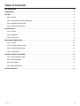 3
3
-
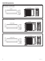 4
4
-
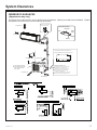 5
5
-
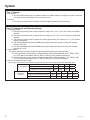 6
6
-
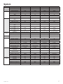 7
7
-
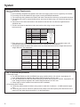 8
8
-
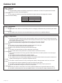 9
9
-
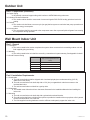 10
10
-
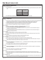 11
11
-
 12
12
-
 13
13
-
 14
14
-
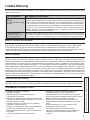 15
15
-
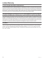 16
16
-
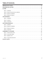 17
17
-
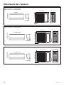 18
18
-
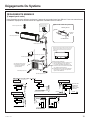 19
19
-
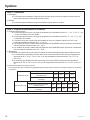 20
20
-
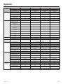 21
21
-
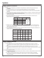 22
22
-
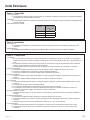 23
23
-
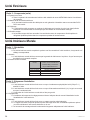 24
24
-
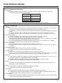 25
25
-
 26
26
-
 27
27
-
 28
28
-
 29
29
-
 30
30
-
 31
31
-
 32
32
-
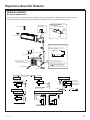 33
33
-
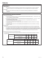 34
34
-
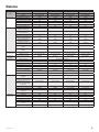 35
35
-
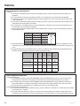 36
36
-
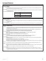 37
37
-
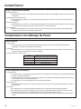 38
38
-
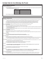 39
39
-
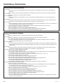 40
40
-
 41
41
-
 42
42
-
 43
43
-
 44
44


GE Caliber Guía del usuario
- Tipo
- Guía del usuario
en otros idiomas
- français: GE Caliber Mode d'emploi
- English: GE Caliber User guide
Artículos relacionados
Otros documentos
-
Haier AD18SL2VHA Installation Instructions Manual
-
LG LMNC126BTG0.AMWALMH Guía de instalación
-
-
HTW SPLIT MURAL VRF UNIDAD INTERIOR Manual de usuario
-
LG A3UW36GFAB.AWGTLAR Manual de usuario
-
Sanyo SPW-XR254EH56 Manual de usuario
-
Toshiba 1FT-E Manual de usuario
-
Friedrich MR36TQY3JM El manual del propietario