La página se está cargando...

,2*
(1*/,6+
a
(63$12/
Than
k you for selecting our product. We are condent we can fully satisfy
your expectations by offering you a wide range of technologically advanced
products which directly result from our many years of experience in faucet
and tting production.
Muchas gracias por elegir nuestro producto. Estamos seguros que podemos
atisfacer completamente sus expectativas ofreciéndole una amplia variedad
de productos tecnológicamente avanzados que resultan directamente de
muchos años de experiencia en grifos y su producción apropiada.
D
e
a
r
Customer Estimado Cliente
I
n
s
t
allation Instructions Instrucciones de Instalación
1
1/2”
& 3/4” THERMOSTATIC VALVE
VÁLVULA TERMOSTATICA 1/2” Y 3/4”
For care, use soft towel with soap and water only!
Under no circumstances should you use any chemicals.
Para el cuidado, utilice solamente una toalla suave
con jabón y aqua! Bajo ninguna circunstanciano
use productos químicos.
ATTENTION! ATENCIÓN!
8036
T
h
e
r
mostatic Valve Trim Only /without Handle/
Sólo el Acabado de la Válvula Termostática /sin el Manilla/
øøPP
øøPP
aaPP
LM24S LM25B LM42SLM37S
Matching TRANQUILITY Series
Cuadra con la serie TRANQUILITY
Matching ATRIA Series
Cuadra con la serie ATRIA
Matching SENTO Series
Cuadra con la serie SENTO
Matching M.E., M.E.25 Series
Cuadra con la serie M.E., M.E.25
8041
Thermostatic Valve Trim Only /without Handle/
Sólo el Acabado de la Válvula Termostática /sin el Manilla/
PP
PP
aaPP
øøPP
8046
Ther
mostatic Valve Trim Only /without Handle/
Sólo el Acabado de la Válvula Termostática /sin el Manilla/
PP
PP
aaPP
øøPP
ø2" (ø50mm)
Recommended handles to be used with:
•
with Trim 8036
Uso de manecillas se recomienda con:
•
con acabado 8036
C10SC9S C14S
Matching TARGA, SADE, LUNA Seri
es
Cuadra con la serie TARGA, SADE, LUNA
Matching FONTAINE Series
Cuadra con la serie FONTAINE
Matching IMMERSION Series
Cuadra con la serie IMMERSION
LM31S LM38SLM23S
Matching SOLAR, STRUCTURE Series
Cuadra con la serie SOLAR, STRUCTURE
Matching QUBIC Series
Cuadr
a con la serie QUBIC
Matching STEALTH Series
Cuadra con la serie STEALTH
LM40SLM39S
Matching QUBIC TRE Series
Cuadra con la serie QUBIC TRE
Matching IMMERSION Series
Cuadra con la serie IMMERSION
Recommended
handles to be
used with:
•
with Trim 8046
•
with Trim 8041
Uso
de manecillas
se recomienda
con:
•
con acabado 8046
•
con acabado 8041
Rev. 5 January 2014
LM45S
Matching
Series
Cuadra con la serie
HASE
P
HASE
P

,2* ,2*
5HY-XQH
R1
R2
L1
L2
T1
T2
T3
T4
T5
T6
T7 T8
M
R2
2
SHOWER
DUCH
A
TUB
BOQUILLA
COLD
FRÍA
HOT
CALIENTE
R1
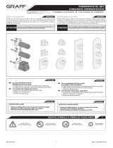
TH
ERMOSTATIC VALVE VÁLVULA TERMOSTÁTICA
T4
TEFLON
®
SL
IP RING ANILLO DE CORREDERA DE TEFLON
®
R2
TE
MPERATURE LIMITING RING ANILLO LIMITADORE TEMPERATURA
T5
TEMPERATURE SCALE DIAL DISCO DE LA ESCALA DE TEMPERTURAS
T1
SLEEVE CASQUILLO
T6
SCREW WITH WASHER TORNILLO CON ARANDELA
T2
O-RING SEAL SELLADOR DE ANILLO
T7
SPLINE ADAPTER CONECTOR DE POLICHAVETA
T3
INDICATOR RING ANILLO INDICADOR
T8
SHORT SCREWS (2 PIECES) TORNILLOS CORTOS (2 PIEZAS)
1.1 1.2
2
ESPAÑOLENGLISH
MIXING V
ALVE TRIM INSTALLATION
•
INSTALACIÓN DE LA GUARNICIÓN DE LA VÁLVULA MEZCLADORA
SEE FIG. 1.1, 1.2, 2
1. Make
sure marked line on spline (L1) and marked line on
cartridge (L2) are centered at top of valve.
2. Install temperature limiting ring (R2) making sure the tab
is aligned with bottom left screw hole as indicated by large
arrow on FIG. 1.1.
3. Install threaded sleeve (T1) on to thermostatic valve
(R1).
4. Install (T2.1) on (T3) if not already installed.
5. Install (T3) into (T1) making sure that indicator mark
(M) is centered at top of valve.
6. Install (T4) inside (T3) if not already installed.
7. Install temperature scale dial (T5) with the 100 degree
setting centered at top of valve aligned with indicator
mark (M).
8. Secure dial (T5) with washer and screw (T6). Install (T7)
and (T8).
9. At this point the valve can be tested for proper temperature
and operation. If the valve is NOT producing the indicated
set temperature proceed to step 10. If valve is producing
the indicated set temperature but you want to adjust
the maximum temperature refer to FIG. 2. If the valve
is producing the indicated set temperature and maximum
temperature correct then continue page 3.
10. Uninstall in reverse order of installation from step 9 until
step 2.
11. Slowly rotate (L2) in small increments counter-clockwise
(will raise temperature) and clockwise (will lower
temperature) to recalibrate cartridge to the 100 degree
setting. When temperature setting is correct refer to step 2.
VER LAS FIG. 1.1, 1.2, 2
1. Asegúrese de que la línea marcada en la polichaveta (L1)
y la línea marcada en el cartucho (L2) estén centradas en
la parte superior de la válvula.
2. Instale el anillo limitador de temperatura (R2); asegúrese
de que la proyección esté alineada con el agujero del
tornillo de la parte inferior izquierda, como lo indica la
flecha grande en la figura 1.1.
3. Instale el casquillo roscado (T1) en la válvula termostática
(R1).
4. Instale (T2.1) en (T3) si aún no está instalado.
5. Instale (T3) en (T1) y asegúrese de que la marca
indicadora (M) esté centrada en la parte superior de la
válvula.
6. Instale (T4) dentro de (T3) si aún no está instalado.
7. Instale el disco de la escala de temperaturas (T5) con la
graduación de 100 grados centrada en la parte superior de
la válvula alineada con la marca indicadora (M).
8. Asegure el disco (T5) con la arandela y el tornillo (T6).
Instale (T7) y (T8).
9. En esta etapa, se puede probar la válvula para determinar
la temperatura y el funcionamiento adecuados. Si la válvula
NO produce la temperatura establecida indicada, continúe
con el paso 10. Si la válvula produce la temperatura
establecida indicada pero desea ajustar la temperatura
máxima, consulte la figura 2. Si la válvula produce
la temperatura establecida indicada y la temperatura
máxima es correcta, continúe en la página 3.
10. Desinstale en orden inverso a la instalación desde el
paso 9 hasta el paso 2.
11. Rote (L2) despacio y de a poco en sentido contrario a
las agujas del reloj (se elevará la temperatura) y en el
sentido de las agujas del reloj (disminuirá la temperatura)
para volver a calibrar el cartucho a la graduación de
100 grados. Cuando la graduación de la temperatura sea
correcta, consulte el paso 2.
Higher setting of
maximum temperature –
remove the temperature limiting ring from
the stem and rotate the ring counterclockwise.
Temperatura máxima más alta – quite el anillo
limitador de temperatures del la espiga y gírelo
el anillo hacia la izquierda
Lower setting of maximum temper
ature –
remove the temperature limiting ring from
the stem and rotate the ring clockwise.
Temperatura máxima más baja– quite el anillo
limitador de temperatures del la espiga y gírelo
el anillo hacia la derecha
Limiting block of t
he temperature limiting ring
Limitador en el anillo limitador de temperaturas
NOTE: Adjustment o
f 1 spline equals 2 degrees.
NOTA: El ajuste de 1 ranura de la polichaveta
equivale a 2 grados.
I
n
stallation Instructions Instrucciones de Instalación
1/
2” & 3/4” THERMOSTATIC VALVE
VÁLVULA TERMOSTATICA 1/2” Y 3/4”
Rev. 5 January 2014

,2*
5HY-XQH
,2*
3
ES
PAÑOL
EN
GLISH
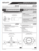
ESCUTCHEON AND HANDLE INSTALLATION
•
INSTALACIÓN DEL ESCUDO Y LA MANILLA
SEE FIG. 3
1.
Open hot and cold CHECK STOPS by using a at-bladed
screwdriver and fully turning the screws counter-clock-
wise.
2. Place non-abrasive PH balanced dish soap around (T1),
(T3) and (T5).
3. Make sure o-ring in (T9) is seated properly. Apply clear
silicon around the back of (T9) and slide it so (T1) ts in
the designated hole. Now push and hold rmly against the
wall. (Optional trim ring (T13) is supplied with the trim
and can be used to hold (T4) on the wall).
4. Install (T10) and (T11).
VER LA FIG. 3
1. Abra los DISPOSITIVOS DE RETENCIÓN de frío y calor con
un destornillador de punta plana y gire los tornillos por
completo en sentido contrario a las agujas del reloj.
2. Coloque detergente no abrasivo con pH balanceado alre-
dedor de (T1), (T3) y (T5).
3. Asegúrese de que la junta tórica de (T9) esté colocada
correctamente. Aplique silicona transparente alrededor de
la parte posterior de (T9) y deslícela de modo que (T1) se
ajuste en el agujero designado. Ahora empuje y sostenga
con rmeza contra la pared. (El anillo de ajuste opcional
(T13) se provee con la guarnición de la válvula y se puede
usar para sostener (T4) en la pared).
4. Instale (T10) y (T11).
ES
PAÑOL
EN
GLISH
CARE AND MAINTENANCE / WARRANTY
•
CUIDADO Y MANTENIMIENTO / GARANTÍA
•
Your Graff product is designed and engineered in accor-
dance with the highest quality and performance stan-
dards.Be sure not to damage the nish during installation.
Care should be given to the cleaning of this product. Al-
though its nish is extremely durable, it can be damaged
by harsh abrasives or polish. Never use abrasive cleaners,
acids, solvents, etc. to clean any Graff product. To clean,
simply wipe gently with a damp cloth and blot dry with a
soft towel.
•
Warranty conditions and warranty registration card are
outlined on a separate sheet.
•
Su válvula de la Graff esta diseñado y dirigido acuerdo
con los estándares de funcionamiento y calidad más altos.
Este seguro no dañar las terminaciones del grifo durante
la instalación. Cuide el producto manteniendolo siempre
limpio. Aunque su acabado es extremadamente durable,
puede ser dañado por los abrasivos o pulientes ásperos.
Nunca utilice limpiadores abrasivos, ácidos, solventes, el
etc. para limpiar cualquier producto de la Graff. Para lim-
piar, simplemente use un paño húmedo y seque con una
toalla suave.
•
Las condiciones de la garantía y la tarjeta del registro de
la garantía se encuentran en una pagina separada.
6,'(9,(:9,67$/$7(5$/
T9
R1
T10
T13T1 T3 T5
T11
T12
T14
K
3
T9
CUBIERTA CON SELLADOR
T10
CUBIERT
A DE LA VÁLVULA
T11
MANILLA
T12
TORNILLO DE LA MANILLA
T13
ANILLO DE APRIETE
“EL USO OPCIONAL”
T14
TORNILLO
T9
PLATE WITH SEALING
T10
V
ALVE COVER
T11
HANDLE
T12
HANDLE SCREW
T13
TRIM RING “OPTIONAL USE”
T14
SCREW
EN
GLISH
ES
PAÑOL
All dimensions and dra
wings are for reference only. For details, please refer to actual products.
Todas las dimensiones y dibujos sirven únicamente de referencia. Para consultar detalles, ver los productos.
HOTLINE FOR HELP
NUMER
O DE EMERGENCIA
For toll-free information and answers
to your questions, call:
Llame sin costo para obteiner informacion
y respestas a sus preguntas:
1 - 800 - 954 - GRAF (4723)
www.gra-faucets.com
I
n
stallation Instructions Instrucciones de Instalación
1/
2” & 3/4” THERMOSTATIC VALVE
VÁLVULA TERMOSTATICA 1/2” Y 3/4”
Rev. 5 January 2014
1/3