Dorel Ameriwood Essential Home Grayson Armoire 5534301KP El manual del propietario
- Tipo
- El manual del propietario

B345534301KP00
OWNER'S MANUAL
Grayson Armoire
5534301KP
caution
carefully read instructions and procedures for safe operation
upc code
0-2998655342-3
product code
0-07049242-6
date of purchase
_____/_____/_____
receipt of purchase
attach here
essentialhome
TM
Please Recycle
Recicle Por Favor
Réutilisez SVP


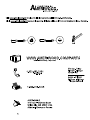
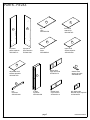
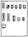
PARTS - PIEZAS
B345534301KP00
page 3
left panel
panel izquierdo
35534301011
right panel
panel derecho
35534301021
drawer back
cajon trasero
35534302110
drawer front
cajon del frente
35534301101
adjustable shelf
estante ajustable
35534301070
bottom
fondo
35534000041
top
cime
35534301030
2 doors
2 puertas
35534301090
fixed shelf
estante fijo
35534301051
upper shelf
estante superior
35534301061
kick
retroceso
35534301081
drawer brace
soporte de cajón
35534000120
left drawer side
lado del cajón izquierdo
35534302130
A
B
C
D
E
F
G
H
I
J
K
L
M

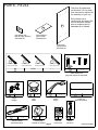
PARTS - PIEZAS
B345534301KP00
page 4
drawer bottom
cajon inferior
35534302150
back panel
panel trasero
K553430101
right drawer side
lado del cajón derecho
35534302140
right cabinet memberleft cabinet member left drawer runner right drawer runner
corredera de mueble derechacorredera de mueble izquierda deslizador izquierdo de cajón deslizador derecha de cajón
111
1
1
x
#A56030
cdb
a
1
x
4
2
#A51401
knob
perilla
x
5
2
A51406
handle
manija
x
36
A65615
hinge
bisagra
x
61
I20490
closet rod
barra del armario
x
7
2
A54230
drawer bracket
soporte del cajón
x
2
1
#A84050
safety bracket kit
juego del soporte de seguridad
x
8
2
A82020
rod bracket
soporte de la barra
x
913
#A22500
cam lock
cerradura de leva
x
10
13
cam bolt
#A22510
perno de leva
N
O
P
This piece is paperboard
construction. It is not made
from wood but is required for
the assembly of your unit.
Esto pedazo son la
construcción del cartón. Ello
no son hecho de madera,
pero se requlere para la
asamblea de su unidad.

PARTS - PIEZAS
B345534301KP00
page 5
x
11
3
#A21520
compression dowel
clavija de compresion
x
12
2
#A53600
angle bracket
anaquel del ángulo
x
13
10
#A12120
7/16" pan head
cabeza redondo 7/16"
12
#A11080
14
7/16" cabeza plano
7/16" flat head
x
x
15
2
#A11170
5/8" pan head
cabeza redondo 5/8"
x
16
2
#A89020
plastic stop
parada de plástico
cabeza plano 1 3/4"
1 3/4" flat head
x
#A13410
17
4
x
18 6
#A11600
1-1/4" flat head
cabeza plano 1-1/4"
x19 6
#A17400
7/8" machine screw
7/8" tornillo
x20 6
#A80250
shelf support
soporte de estante
x
21
54
#A21110
nail
clavo
arandela
washer
422
#A25400
x

B345534301KP00
page 6
2
3
½ turn to fully
lock.
½ se vuelven a
totalmente
cerradura.
4
Tighten to fully seat. Do not over
tighten.
Apriétese a totalmente asiento. No
haga encima de apriétese.
Proper orientation of cam.
La orientación apropiada de leva.
1
This illustration shows how the CAM fastening system works.
Esta ilustración muestra el sistema de fijación de leva y como funciona.
Lock
Apretar

B345534301KP00
page 7
1
x
10
6
x
33
x
8
1
x
14
4
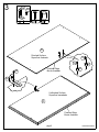
Finished Edge
Borde Acabado
A
Loosen to seperate.
Desajuste para separar.
3
8
10
10
1
a
x
1
1a
14
14

B345534301KP00
page 8
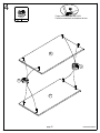
2
x
33
x
81
x
10
6
x
14 4
b
1
x
1
Loosen to seperate.
Desajuste para separar.
10
10
1b
3
8
14
Finished Edge
Borde Acabado
B
14

B345534301KP00
page 9
3
x
2
1
x
16
2
x
15
2
15
15
16
16
2a
2b
Finished Edge
Borde Acabado
Finished Edge
Borde Acabado
C
C
Finished Surface
Superficie Acabado
Unfinished Surface
Superfice Inacabado
2a
2b

B345534301KP00
page 10
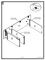
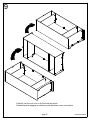
4
x
98
Proper orientation of CAM LOCK
Posición correcta de la cerradura de leva.
9
9
E
F

B345534301KP00
page 11
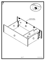
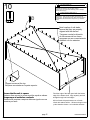
5
Proper orientation of CAM LOCK
Posición correcta de la cerradura de leva.
x
94
x
11
2
12
2x
x
13 4
End View
Vista Final
Approx.
7/16"
11
9
9
11
11
12
13
13
D
H

B345534301KP00
page 12
6
UNLOCK
LOCK
APRETAR
DESAPRETAR
A
D
H
E
F
Finished Edge
Borde Acabado
Finished Edge
Borde Acabado
Finished Edge
Borde Acabado

B345534301KP00
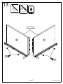
page 13
7
UNLOCK
LOCK
APRETAR
DESAPRETAR
Finished Edge
Borde Acabado
E
H
D
F
A
B

B345534301KP00
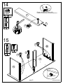
page 14
8
17
x
4
17
Finished Edge
Borde Acabado
A
B
C

B345534301KP00
page 15
9
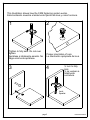
Carefully turn the unit over on its front side as shown.
Cuidadosamente apague la unidad su parte delantera como se muestra.

B345534301KP00
page 16
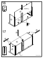
10
Assure that the unit is square.
Distance from corner to corner must be equal as shown.
Asegura que el unidad es cuadrada.
Distancia de esquina a esquina debe ser igual como se
muestra por favor.
Flush the edge of the back panel with the bottom
edge of the bottom shelf. Align squarely and nail
straight through into back edges.
Alinie el borde del panel trasero con el borde
inferior del estante inferior. Allinee en ángulo recto
y clave derecho dentro o en los bordes traseros.
21
x54
and/or serious injury.
Por favor asegúrese que el Panel Trasero se atan
firmemente. Todos los clavos deben manejarse en las
partes recto. El fracaso para hacer para que podría causar
inestabilidad, derrumbamiento del producto, y/o la lesión
seria.
Failure to do so could cause instability, product collapse,
All nails must be driven into the parts straight.
Please make sure that the Back Panel is attached securely.
ADVERTENCIA
WARNING
21
Clipped corners at the top.
Esquinas recortadas en la parte superior.
Note location of nail stabs,
assure that they are properly
aligned with the shelves
Tenga en cuenta la ubicación
de las marcas de los clavos,
aseguran que son correctamente
alineado con los estantes

B345534301KP00
page 17
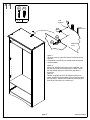
11
Option 1;
Securely screw (2c) into solid area of the wall as shown.
Opción 1;
Firmemente el tornillo (2c) en el área sólida de la pared
como mostrado.
Option 2:
Drill a 3/16" diameter hole (5mm) in the wallboard. Tap
the wall anchor(4d) into the hole until it is flush. Fasten
the wall bracket (2a) to the wall anchor (2d) with the
screw (2c).
Opcion 2:
Taladre un agujero de 3/16" de diámetro (5mm) en la
pared. Golpea la ancla de pared (2d) en el agujero hasta
que sea parejo. Abroche la escuadra de pared (2a) al la
ancla de la pared (2d) con el tornillo (2c).
stud
montante
wallboard
muro
hole
agujero
2a
2c
2d
x
2
1
2c
2d

B345534301KP00
page 18
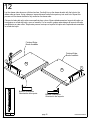
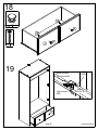
12
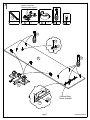
Lay the drawer sides down on a flat hard surface. Carefully line up the drawer bracket with the holes in the
drawer side as shown. Using a hammer, tap each drawer bracket stem part way into each hole. Repeat this
process until the drawer bracket is fully seated on the drawer side.
Coloque los lados del cajón sobre una superficie plana y dura. Alinee cuidadosamente el soporte del cajón con
los agujeros en el lado del cajón, como se muestra. Con un martillo, golpee cada vástago del soporte del cajón
parcialmente en cada orificio. Repita este proceso hasta que el soporte del cajón esté completamente asentado
en el lado del cajón.
Finished Edge
Borde Acabado
Finished Edge
Borde Acabado
Bracket Orientation
Orientación del soporte
Bracket Orientation
Orientación del soporte
M
N
x
7
2
7
7

B345534301KP00
page 19
13
1
c
x
1
1
d
x
1
x
14
4
14
14
1c 1d
Finished Edge
Borde Acabado
M
N

B345534301KP00
page 20
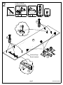
14
15
x
13
6
Approx.
7/16"
11
Proper orientation of CAM LOCK
Posición correcta de la cerradura de leva.
x
91
x
11
1
9
11
L
13
13
UNLOCK
LOCK
APRETAR
DESAPRETAR
M
N
L
J
x
10
1
10

B345534301KP00
page 21
16
17
20 2x
O
N
J
L
M
20
x
18 6
N
L
J
18
18
18
K
raw surface
superficie cruda

B345534301KP00
page 22
18
x19 2
x
4
2
19
19
J
19
corredera de mueble
cabinet member
rodillo
roller
drawer runner
deslizador de cajon
roller
rodillo
J
4
4

B345534301KP00
page 23
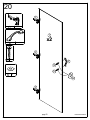
20
x
36
x
5
2
x19 4
3
3
3
5
19
19
I
x2
422
x
22

B345534301KP00
page 24
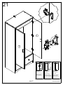
21
Loosen screw C
Adjust door.
Tighten screw C
*side view
Suelte el tornillo C
Ajuste la puerta
Serrar el tornillo C
*la vista lateral
Loosen screw C
Turn screw B to
move door
Tighten screw C
Suelte el tornillo C
Dé vuelta el tornillo B
para mover la puerta
Ajuste el tornillo C
Loosen screw A
Adjust door
Tighten screw A
Suelte el tornillo A
Ajuste la puerta
Serrar el tornillo A
A
B
C
I
I

B345534301KP00
page 25
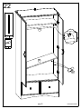
22
20 4x
x
6
1
20
G
6

B345534301KP00
page 26
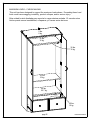
This unit has been designed to support the maximum loads shown. Exceeding these load
limits could cause sagging, instability, product collapse, and/or serious injury.
Esta unidad ha sido diseñada para soportar la carga máxima anotada. El exceder estos
límites puede causar inestabilidad, colapsarse y/o causar serias lesiones.
MAXIMUM LOADS – CARGA MAXIMA
50 lbs.
22.7 kg.
35 lbs.
15 kg.
35 lbs.
15 kg.
35 lbs.
15 kg.
35 lbs.
15 kg.
0 lbs.
0 kg.

B345534301KP00
page 27
Certificate of Conformity
1. This certificate applies to the Ameriwood Industries Inc. product identified by this instruction
manual.
2. This certificate applies to compliance of this product with the CPSC Ban on Lead-Containing Paint
(16 CFR 1303).
3. This product is distributed by: Ameriwood Industries Inc.
410 East First Street South
Wright City, MO 63390
1-636-745-3351
4. Site of Manufacture:
□ Cornwall ON
5. See front page of instruction manual for date of manufacture.
-
 1
1
-
 2
2
-
 3
3
-
 4
4
-
 5
5
-
 6
6
-
 7
7
-
 8
8
-
 9
9
-
 10
10
-
 11
11
-
 12
12
-
 13
13
-
 14
14
-
 15
15
-
 16
16
-
 17
17
-
 18
18
-
 19
19
-
 20
20
-
 21
21
-
 22
22
-
 23
23
-
 24
24
-
 25
25
-
 26
26
-
 27
27


Dorel Ameriwood Essential Home Grayson Armoire 5534301KP El manual del propietario
- Tipo
- El manual del propietario
en otros idiomas
Artículos relacionados
-
Dorel 5531309KP El manual del propietario
-
-
-
Altra Furniture HD93176 Manual de usuario
-
Dorel 5666308PCOM Manual de usuario
-
-