
FRESH IN
TM
BASIC
FIN-180B AND FIN-180B-HW
INSTALLATION INSTRUCTIONS
READ AND SAVE THESE INSTRUCTIONS
⚠RESIDENTIAL USE ONLY⚠
REGISTER YOUR PRODUCT ONLINE AT: www.broan.com/register
VB0260
FIN-180B
6-FT. POWER CORD
FIN-180B-HW
HARDWIRED

22
Please take note that this manual uses the following symbols to emphasize particular information:
⚠WARNING
Identifies an instruction which, if not followed, might cause serious personal injuries
including possibility of death.
CAUTION
Denotes an instruction which, if not followed, may severely damage the unit and/or its
components.
💡 Indicates a supplementary information that may relate to optional parts or simply aim to
facilitate a task.
⚠WARNING
TO REDUCE THE RISK OF FIRE, ELECTRIC SHOCK, OR INJURY TO PERSON(S) OBSERVE THE
FOLLOWING:
1. Use this unit only in the manner intended by the manufacturer. If you have questions, contact the
manufacturer.
2. Before servicing or cleaning this unit, turn power off at service panel.
3. This unit is not designed to provide combustion and/or dilution air for fuel-burning appliances.
4. Do not use this unit with any solid-state speed control device.
5. FIN-180B MODEL ONLY: Do not operate any fan with a damaged cord or plug. Discard fan or contact
your HVAC contractor, or the manufacturer.
6. FIN-180B MODEL ONLY: Do not run cord under carpeting. Do not cover cord with throw rugs, runners
or similar coverings. Do not route cord under furniture or appliances. Arrange cord away from traffic
area and where it will not be tripped over.
7. Installation work must be done by qualified person(s) in accordance with all applicable codes and
standards, including fire-rated construction.
8. When cutting or drilling into a wall or ceiling, do not damage electrical wiring and other hidden utilities.
9. ALL UNITS: This unit must be grounded. FIN-180B MODEL ONLY: The power supply cord has a
3-prong grounding plug for your personal safety. It must be plugged into a mating 3-prong grounding
receptacle, grounded in accordance with the national electrical code and local codes and ordinances.
Do not remove the ground prong. Do not use an extension cord.
10. When servicing, cleaning or performing installation of this unit, it is recommended to wear safety
glasses and gloves.
11. When applicable local regulation comprises more restrictive installation and/or certification requirements,
the aforementioned requirements prevail on those of this document and the installer agrees to conform
to these at his own expenses.
12. The unit must be mounted at least 3.3 feet (1.0 meter) away from any accessible opening of the duct.
CAUTION
1. Please read specification label on product for further information and requirements.
2. Do not intake air into spaces within walls or ceiling or into attics, crawl spaces, or garage. Do not
attempt to recover the exhaust air from a dryer or a range hood.
3. Intended for residential installation only in accordance with the requirements of NFPA 90B.
4. When leaving the house for a long period of time (more than two weeks), a responsible person should
regularly check if the unit operates adequately.
5. At least once a year, the unit mechanical and electronic parts should be inspected by qualified service
personnel.
6. Since the electronic control system of the unit uses a microprocessor, it may not operate correctly
because of external noise or very short power failure. If this happens, turn power off at service panel
and wait approximately 10 seconds. Then, restore the power to the unit.
7. Outdoor intake hood must be weather tight and comprise a bird screen.
8. Should you decide to dispose of this unit or of parts of it, do so in accordance with local laws and
regulation.
9. Some areas are prone to a higher frequency of lightning-induced power surges. Using a surge protector
device to protect units located in these areas is recommended.

33
1. USER SERVICING INSTRUCTIONS
• The metal filter included with this unit should be cleaned every 6 months using water and a mild soap.
To remove the filter(s), open the door, release the filter retaining clip and pull filter(s) out. Allow the
filter to dry completely before putting it back in the unit; when reinserting it in the unit, make sure that
it is standing straight.
• Inspect the outdoor air intake at least once a year.
• During the first year of operation, it is recommended to inspect your unit at a higher frequency,
especially if you live near a highway or in an area where there is a lot of construction work, generating
lots of dust. Your filter(s) may need more frequent cleaning or replacement in these types of
environments.
• Replace the optional MERV filter at least once a year; do not attempt to clean and reuse the optional
MERV filter.
• These recommendations may change according to the environmental conditions in your area.
2. PLANNING
2.1 INSTALLATION ZONES
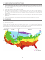
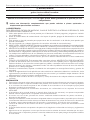
The FIN-180B and FIN-180B-HW can be installed in climatic zones 1 to 4 as defined by the Department
of Energy (refer to the map below), whether as a stand alone unit or connected to the return ducting of an
AHU. Installation in any other climatic zone may cause damage to the house.
VN0011A

44
2.2 INSTALLATION TYPES
CAUTION
Always use insulated ducting of a minimum R-4 insulation factor.
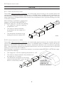
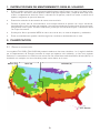
2.2.1 STAND ALONE INSTALLATION
The installer shall ensure that, if necessary, an in-line heater sized according to the required airflow and
outside design heating temperature from Manual J or ASHRAE table is installed to avoid condensation on
uninsulated duct distribution systems within the house or surfaces near the distribution register. The in-line
heater shall have an integrated airflow sensor and an over temperature sensor to prevent heating in no-flow
or low-flow conditions.
When deciding if a preheater is required and
whether it should be installed BEFORE or
AFTER the supply fan, consider the following:
• This supply fan’s minimum operating
temperature is 14 °F.
• The minimum distance between
the preheater and the supply fan is
12 inches.
• The temperature distributed in the
dwelling should not be below 55 °F.
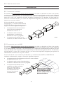
2.2.2 INSTALLATION WITH AN AHU
The installer shall ensure that, if necessary, an in-line heater sized according to the required airflow and
outside design heating temperature from Manual J or ASHRAE table is installed to ensure that the air
delivered to the AHU is never below the minimum temperature allowed by the manufacturer (generally
55 °F). The in-line heater shall have an integrated airflow sensor and an over temperature sensor to prevent
heating in no-flow or low-flow conditions.
When deciding if a preheater is required and whether it should be installed BEFORE or AFTER the supply
fan, consider the following:
• This supply fan’s minimum operating temperature is 14 °F.
• The minimum distance between the preheater and
the supply fan is 12 inches.
• The temperature distributed in the ducting
should not be below 55°F, unless the AHU
blower is continuously running.
VJ0149
AHU
VJ0150
Follow AHU
manufacturer's
guidelines for
minimum distance.

55
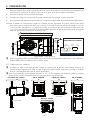
3. PREPARATION
1. Remove the unit from the box and inspect for damage. Installation hardware is located in a plastic bag
along with this guide, on top of the filler.
2. Put the unit down on a protected surface.
3. Refer to your local building code to determine the required airflow.
4. Open the unit’s door to access the settings on the electrical compartment cover.
5. Adjust the settings according to the required airflow. The first number around the Airflow Range
adjustment is the Low Range CFM value (30-100 CFM), and the second number is the High Range
CFM value (110-180 CFM). Use a small flat blade screwdriver to switch from Low Range to High
range, and to adjust the CFM value.
💡 An optional MERV filter may be installed now. The main filter should remain as a prefilter, and the
MERV filter should be installed as indicated above.
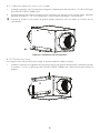
3.1 MOUNTING THE UNIT
💡 When choosing a location for this unit, keep in mind that maintenance will have to be performed by the
end user on a regular basis. Choose an easily accessible location and plan for a 14¼-in. clearance for
the door to open.
💡 For a 16-in. or 24-in. cc joists installation, use the optional bracket FIN-S1624 (see instructions
packed with bracket).
VD0463
AIRFLOW ADJUSTMENT
Low
range
High
range
Refer to the manual for more details. www.broan.com
50/130
60/14070/150
80/160
90/170
100/180
40/120
30/110
Low /
High range
AIRFLOW DIRECTION
MERV Filter Main Filter
With optional
decorative trim
FLUSH TO CEILING
VD0467
12"
ATTIC MOUNTED
VD0466
12"
VH0152
10"
10"
WALL MOUNTED
UNDER CEILING
10¼"
VH0154
10"
CEILING HUNG
VH0153A
14¼" clearance

66
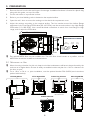
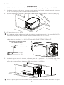
3.1.1 UNDER CEILING OR WALL MOUNTED
1. Using 4 screws no. 8-18 x 0.375 in., install the brackets on the unit as illustrated in Figure A. DO
NOT USE OTHER SCREWS.
2. Using 4 screws no. 10-12 x 0.625 in. or longer screws if necessary, secure the unit to the wall or
ceiling, into the studs, joists or other solid material.
💡 When wall mounted, the unit can be positioned in any orientation to suit your need.
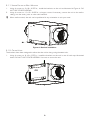
3.1.2 CEILING HUNG
The brackets have been designed to allow that the unit be hung using threaded rods.
1. Using 4 screws no. 8-18 x 0.375 in., install the brackets on the unit in one of both ways illustrated
below. DO NOT USE OTHER SCREWS. Use nuts to secure the unit.
Figure A: Bracket installation
VD0468
VD0465
OR

77
3.1.3 IN THE ATTIC
CAUTION
Do not install in an attic where the temperature may exceed 160 °F.
1. Using 4 screws no. 8-18 x 0.375 in., install the brackets on the unit as illustrated on previous page in
Figure A. DO NOT USE OTHER SCREWS.
2. Using 4 screws no. 10-12 x 0.625 in., secure the unit to the joists or cross framing.
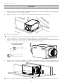
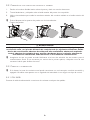
3.1.4 FLUSH-TO-CEILING
💡 If the finishing will be done using the optional decorative finishing trim (part no. FIN-R1015), the
springs included in the optional kit should be installed before installing the brackets.
1. Using 4 screws no. 8-18 x 0.375 in., install the brackets on the unit following the diagram below to
adapt to the thickness of the ceiling. DO NOT USE OTHER SCREWS.
2. Using 4 screws no. 10-12 x 0.625 in., install the unit between the joists. This unit is designed to fit
between 12 in. cc joists. If the joists are closer, do not force the unit in, choose an other installation method.
💡 Prior to painting, clean the metal housing using solvent and the optional decorative trim using water.
VD0469
X
VD0470
X = 5/8"
X = 1 1/4"
X = 1/2"
X = 1 3/8"
SCREW POSITION ACCORDING
TO
CEILING THICKNESS
VD0471

88
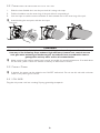
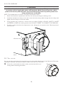
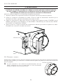
3.2 CONNECTING THE INSULATED DUCTS TO THE UNIT
1. Slide the inner flexible duct over the port and tie it using a tie-wrap.
2. Pull the insulation over the outer ring of the port without compressing it.
3. Use duct tape to seal the outer membrane of the insulated duct to the outer ring of the port.
💡 Avoid blocking the test ports with the duct tape.
⚠WARNING
Make sure the outdoor intake hood is at least 12 inches above the ground and 6 feet away
from any of the following: Dryer exhaust, high-efficiency furnace vent, central vacuum
vent, gas meter exhaust, gas barbecue-grill, any exhaust from a combustion source,
garbage bin and any other source of contamination.
💡 Make sure that the outdoor intake hood is easily accessible for annual maintenance. If located above
the first floor, place it close to a window or balcony to allow ease of access.
3.3 CONNECT POWER
💡 If desired, the power can be related to an ON/OFF wall switch. Do not use this unit with a dimmer
switch or any other type of control.
3.3.1 FIN-180B
Plug the unit power cord into a mating 3-prong grounding receptacle.
Test ports
VJ0151

99
3.3.2 FIN-180B-HW
⚠ WARNING
Risk of electric shock. Electrical wiring must be done by qualified personnel in
accordance with all applicable codes and standards. Before connecting wires, switch
power off at service panel and lock service disconnecting means to prevent power from
being switched on accidentally.
NOTE: The insulated duct not shown to simplify the illustration below.
1. Detach the electrical compartment cover from the unit by removing its retaining screw.
2. Install the included wire clamp on the unit. Insert the house wiring cable through the wire clamp and
tighten the wire clamp to secure the cable.
3. Using provided wire connectors, connect wires as follows: BLACK to BLACK, WHITE to WHITE
and GREEN or BARE wire under ground screw. DO NOT FORGET TO CONNECT THE GROUND.
4. Put back in place the electrical compartment cover, taking care not to pinch wires. Restore power at
service panel.
VE0424
Ground screw
3.4 TEST THE UNIT
You may test the unit at this point using the test port on the intake side (closest to the filter) and a Pitot tube.
The distance between the test port and the center of the duct is 3.75 inches.
💡 If the unit is connected to an AHU, make sure that the AHU is not
running while measuring the airflow.
VD0472
Test ports

1010
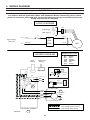
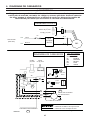
4. WIRING DIAGRAM
⚠WARNING
Risk of electric shock. Electrical wiring must be done by qualified personnel in
accordance with all applicable codes and standards. Before connecting wires, switch
power off at service panel and lock service disconnecting means to prevent power from
being switched on accidentally.
LOGIC DIAGRAM
WIRING COLOR CODE
BLK BLACK
BLU BLUE
GRN GREEN
ORG ORANGE
RED RED
WHT WHITE
Line
voltage
factory
wiring
Low
voltage
factory wiring
Low
voltage
field wiring
BLK
Supply fan
motor
ORG
BLU
RED
WHT
Power
cable
1
1
1
F1
J10
J2
J1
Control cable
M1
GRN
WHT
BLK
A1
ELECTRONIC ASSEMBLY
CFM Range
Seng
CFM
Seng
WIRING DIAGRAM
Low
High
Ref: 99046030_REV-B
VE0421A
M1
Line
Neutral
AC
Line
Filter
J1-2
F1
High Voltage
(120 VAC)
J1-1
J10
J2-1
J2-2
CFM Range
CFM Seng
GRN
WHT
BLK
120 VAC,
60 Hz
Line
Neutral
Ground
120 VAC,
60 Hz
W1
GRN
WHT
BLK
FIN-180B
FIN-180B-HW

1111
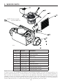
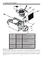
5. SERVICE PARTS
Item no. Part no. Desription
1 S97021042 Damper Assembly
2 S97021044 Motor Assembly
3 S97021045 Main Filter
4 S97021048 Electronic Cover
5 S97021046 Electronic Board
6 S97021041 6-in. Port
Not shown FIN-S1624 Optional Bracket
Not shown FIN-R1015 Optional Decorative Trim
Not shown S99010461 Optional MERV 8 Filter
Not shown S99010462 Optional MERV13 Filter
VL0081
1
2
4
3
5
6
Replacement Parts and Repair
In order to ensure your ventilation unit remains in good working condition, you must use Broan-NuTone LLC
genuine replacement parts only. The Broan-NuTone LLC genuine replacement parts are specially designed for
each unit and are manufactured to comply with all the applicable certification standards and maintain a high
standard of safety. Any third party replacement part used may cause serious damage and drastically reduce the
performance level of your unit, which will result in premature failing. Also, Broan-NuTone LLC recommends to
contact a Broan-NuTone LLC certified service depot for all replacement parts and repairs.
NOTE: Power cord only
for FIN-180B unit.

1212
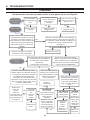
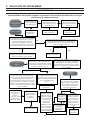
6. TROUBLESHOOTING
⚠WARNING
Risk of electric shock. Before performing any maintenance or servicing, always
disconnect the unit from its power source or turn power off at service panel.
NO
NO
NO
Unit is noisy
Inspect the unit f or damage during
transportation (warped or kicked
housing for example). Perform a
visual inspection of the inside of the
unit. Is any component touching
the blower wheel or i s there any
damage?
Remove any debris or contact
customer service if damaged.
Perfor m a visu al inspe ction of t he d amp er .
Can the dam per ope n and c lose normal ly ?
(The damper is held closed by a magnet. It is
normal to fe el some resis tance when
opening it.)
Replace the motor
Remove any obstacle hindering
damper move ment. If accumulated
dust caused this issue, make sure
that the filter is present, and consider
using an optional MERV filter.
Unit does not
deliver required
airflow
Are the airflow
settings properly
set?
Restore proper
settings
Are the filter, outdoor
hood o r d istribution
grille clogged or
blocked?
Is the measuring tool
accurate? Try usi ng a
different tool.
Calibrate tool
Damper does not
close
If the ductwork of the supply fan
is connected to the ductwork of
an AHU, turn OFF the AHU
temporarily.
Is the damper now closed?
Make sure that the unit
duc twork is connec te d to
the supply ductwork of the
AHU, and not on the
return ductwork.
Perfor m a visu al inspe ction of t he
damper. Make sure that the damper
can open and cl os e f re ely . Remove
any obstacle hindering damper
movement. If accumulated dust
cause d this is sue, make sure that the
filter is present, and consider using
an optional MERV fi lter.
Replace or clean
clogged parts
NONO YES
YES
YES
YES
YES
NO
YESNO
Unit does not work
If the unit is connected to
the ductwork of an AHU,
turn OFF the AHU. Open
unit’s door and val idate
that unit really does not
work.
FIN-180B
Use a small
electric
appliance to
test the wall
outlet. Does
the wall
outlet work
properly?
Refer to an
electrician.
FIN-180B-HW:
Are the wire
connections coming
from house power
cable secured
properly?
All units: Are both
motor connectors
(J2 and J10) well
connected to the
electronic board?
Restore
connections.
Is the fuse
located on
the
electronic
board
blown?
Replace the
electronic
board.
If this is a
recurrent issue, it
may indicate that
the motor has to
be replaced.
Replace the
motor.
NO
YES
NO
YES
YES
FIN-180B-HW
Is there power
coming from
service panel?
Check for
tripped
circuit
breaker.
Refer to an
electrician.
NO
YES

1313
7. WARRANTY
Warranty Period and Exclusions: Broan-NuTone LLC (the "Company") warrants to the original consumer purchaser of its product ("you")
that the product (the "Product") will be free from material defects in the Product or its workmanship for five (5) years, starting on the date you
purchase the Product.
The limited warranty period for any replacement parts provided by the Company and for any Products repaired or replaced under this limited
warranty shall be the remainder of the original warranty period.
This warranty does not cover fluorescent lamp starters, tubes, halogen and incandescent bulbs, fuses, filters, ducts, roof caps, wall caps and
other accessories for ducting that may be purchased separately and installed with the Product. This warranty also does not cover (a) normal
maintenance and service, (b) normal wear and tear, (c) any Products or parts which have been subject to misuse, abuse, abnormal usage,
negligence, accident, improper or insufficient maintenance, storage or repair (other than repair by the Company), (d) damage caused by faulty
installation, or installation or use contrary to the recommendations or instructions of the Company or its representatives, (e) any Product that
has been moved from its original point of installation, (f) damage caused by environmental or natural elements, (g) damage in transit, (h) natural
wear of finish, (i) Products in commercial or nonresidential use, (j) damage caused by fire, flood or other act of God, (k) consumable parts,
(l) cosmetic damage, including but not limited to scratches or dents, or (m) Products with altered, defaced or removed serial numbers. This
warranty covers only Products sold to original consumers in the United States and Canada by the Company or its U.S. and Canadian distributors
authorized by the Company.
This warranty supersedes all prior warranties and, subject to applicable law, is not transferable from the original consumer purchaser.
No Other Warranties: To the maximum extent permitted by applicable law, this limited warranty contains the Company’s sole obligation
and your sole remedy for defective products. The foregoing warranties are exclusive and in lieu of any other warranties and conditions,
express or implied. THE COMPANY DISCLAIMS AND EXCLUDES ALL OTHER EXPRESS WARRANTIES AND CONDITIONS, AND
DISCLAIMS AND EXCLUDES ALL WARRANTIES AND CONDITIONS IMPLIED BY LAW, INCLUDING WITHOUT LIMITATION THOSE
OF MERCHANTABILITY AND FITNESS FOR A PARTICULAR PURPOSE. To the extent that applicable law prohibits the exclusion of implied
warranties or conditions, the duration of any applicable implied warranty or condition is limited to the period specified for the express warranty
above. Some jurisdictions do not allow limitations on how long an implied warranty lasts, so the above limitation may not apply to you. Any oral
or written description of the Product is for the sole purpose of identifying it and shall not be construed as an express warranty.
Whenever possible, each provision of this Limited Warranty shall be interpreted in such manner as to be effective and valid under applicable
law, but if any provision is held to be prohibited or invalid, such provision shall be ineffective only to the extent of such prohibition or invalidity,
without invalidating the remainder of such provision or the other remaining provisions of the Limited Warranty.
Remedy: During the limited warranty period as stated above, the Company will, at its option, provide replacement parts for, or repair or replace,
without charge, any Product or part thereof, to the extent the Company finds it to be covered by and in breach of this limited warranty under
normal use and service. The Company will ship the repaired or replaced Product or replacement parts to you in the United States or Canada at
no charge. You are responsible for all costs for removal, reinstallation and shipping, insurance or other freight charges incurred in the shipment
of the Product or part to the Company. If you must send the Product or part to the Company, as instructed by the Company, you must properly
pack the Product or part—the Company is not responsible for damage in transit. The Company reserves the right to utilize reconditioned,
refurbished, repaired or remanufactured Products or parts in the warranty repair or replacement process. Such Products and parts will be
comparable in function and performance to an original Product or part and warranted for the remainder of the original warranty period.
The Company reserves the right, in its sole discretion, to refund the money actually paid by you for the Product in lieu of repair or replacement.
If the Product or part is no longer available, replacement may be made with a similar product of equal or greater value, at the Company’s sole
discretion.
Exclusion of Damages: THE COMPANY’S OBLIGATION TO PROVIDE REPLACEMENT PARTS, OR REPAIR, REPLACE OR REFUND,
AT THE COMPANY’S OPTION, SHALL BE YOUR SOLE AND EXCLUSIVE REMEDY UNDER THIS LIMITED WARRANTY AND THE
COMPANY’S SOLE AND EXCLUSIVE OBLIGATION. TO THE EXTENT PERMITTED BY THE APPLICABLE LAW, THE COMPANY
SHALL NOT BE LIABLE FOR INCIDENTAL, INDIRECT, CONSEQUENTIAL OR SPECIAL DAMAGES ARISING OUT OF OR IN
CONNECTION WITH THE PRODUCT, ITS USE OR PERFORMANCE. Incidental damages include, but are not limited to, such damages as
loss of time and loss of use. Consequential damages include, but are not limited to, the cost of repairing or replacing other property which is
damaged if the Product does not work properly.
TO THE EXTENT PERMITTED BY THE APPLICABLE LAW, THE COMPANY SHALL NOT BE LIABLE TO YOU, OR TO ANYONE
CLAIMING UNDER YOU, FOR ANY OTHER OBLIGATIONS OR LIABILITIES, INCLUDING, BUT NOT LIMITED TO, OBLIGATIONS
OR LIABILITIES ARISING OUT OF BREACH OF CONTRACT OR WARRANTY, NEGLIGENCE OR OTHER TORT OR ANY THEORY OF
STRICT LIABILITY, WITH RESPECT TO THE PRODUCT OR THE COMPANY’S ACTS OR OMISSIONS OR OTHERWISE.
Some jurisdictions do not allow the exclusion or limitation of incidental or consequential damages, so the above limitation or exclusion may not
apply to you. This warranty gives you specific legal rights, and you may also have other rights, which vary from jurisdiction to jurisdiction. The
disclaimers, exclusions, and limitations of liability under this warranty will not apply to the extent prohibited by applicable law.
This warranty covers only replacement or repair of defective Products or parts thereof at the Company’s main facility, or such other facility as
Company may designate from time to time, and does not include the cost of field service travel and living expenses, which expenses shall be
disclosed to and accepted by you in advance.
Any assistance the Company provides to or procures for you outside the terms, limitations or exclusions of this limited warrant
y will not constitute
a waiver of such terms, limitations or exclusions, nor will such assistance extend or revive the warranty.
The Company will not reimburse you for any expenses incurred by you in repairing or replacing any defective Product, except for those incurred
with the Company’s prior written permission.
How to Obtain Warranty Service: To qualify for warranty service, you must (a) notify the Company at the address or telephone number stated
below within seven (7) days of discovering the covered defect, (b) give the model number and part identification, and (c) describe the nature
of any defect in the Product or part. At the time of requesting warranty service, you must present evidence of the original purchase date. If
you cannot provide a copy of the original written limited warranty, then the terms of the Company’s most current written limited warranty for
your particular product will control. The most current limited written warranties for the Company’s products can be found at www.broan.com.
Broan-NuTone LLC, 926 West State Street, Hartford, WI 53027 800.558.1711

FRESH IN
TM
BASIC
FIN-180B Y FIN-180B-HW
INSTRUCCIONES DE INSTALACIÓN
LEA Y GUARDE ESTAS INSTRUCCIONES
⚠PARA USO RESIDENCIAL ÚNICAMENTE⚠
REGISTRE SU PRODUCTO EN LÍNEA EN: www.broan.com/register
VB0260
FIN-180B
CABLE DE
ALIMENTACIÓN DE 6 PIES
FIN-180B-HW
CABLEADO

22
Este manual utiliza los siguientes símbolos para hacer hincapié en determinada información:
⚠
ADVERTENCIA
Se refiere a una instrucción que, si no se sigue, puede provocar lesiones personales
graves, incluso causar la muerte.
PRECAUCIÓN
Denota una instrucción que, si no se sigue, puede dañar gravemente el aparato y/o sus
componentes.
💡 Indica una información complementaria que puede referirse a piezas opcionales o
simplemente para facilitar una tarea.
⚠ADVERTENCIA
PARA REDUCIR EL RIESGO DE INCENDIO, CHOQUE ELÉCTRICO O HERIDAS CORPORALES, SIGA
LAS INDICACIONES SIGUIENTES:
1. Utilice este aparato sólo en la forma prevista por el fabricante. Si tiene preguntas, póngase en contacto
con el fabricante.
2. Antes de realizar tareas de mantenimiento o de limpiar el aparato,
apague la alimentación en el tablero
de servicio.
3. Este aparato no ha sido pensado para proporcionar aire de combustión o de dilución para aparatos que
queman combustible.
4. No use el aparato con cualquier dispositivo de control de velocidad de semiconductores.
5. MODELO FIN-180B SOLAMENTE:
No utilice un ventilador con un cable o enchufe dañado. Deseche el ventilador
o póngase en contacto con su contratista de calefacción, ventilación y aire acondicionado o con el fabricante.
6. MODELO FIN-180B SOLAMENTE:
No haga pasar el cable por debajo de una alfombra o moqueta. No cubra
el cable con alfombrillas, tapetes u otros recubrimientos similares. No pase el cable por debajo de muebles o
electrodomésticos. Haga pasar el cable lejos de las zonas de circulación y donde nadie pueda tropezarse con él.
7. Los trabajos de instalación han de ser realizados por personas cualificadas, de conformidad con todos los
códigos y normas aplicables, incluyendo los relativos a la construcción contra incendios.
8. Al cortar o taladrar en una pared o en el techo, procure no dañar el cableado eléctrico ni otras instalaciones
ocultas.
9. TODOS LOS APARATOS:
Este aparato debe conectarse a tierra
. MODELO FIN-180B SOLAMENTE:
El cable de alimentación lleva un enchufe con toma de tierra de 3 patillas para su seguridad personal.
Debe enchufarse en una toma de corriente para tres patillas, conectada a tierra de acuerdo con el código
eléctrico nacional y los códigos y ordenanzas locales. No retire la patilla de la toma de tierra. No utilice el
aparato con un cable prolongador.
10. Durante el mantenimiento, limpieza e instalación de este aparato se aconseja llevar lentes y guantes de
seguridad.
11. Cuando la reglamentación local aplicable sea más restrictiva en materia de instalación o certificación, dicha
reglamentación prevalecerá sobre las exigencias de este manual y el instalador acepta atenerse a dicha
reglamentación y asumir los gastos correspondientes.
12. El aparato debe montarse al menos a 3,3 pies (1 metro) de distancia de cualquier abertura accesible del
conducto.
PRECAUCIÓN
1. Para mayor información sobre otras exigencias, lea la etiqueta de especificaciones que viene en el aparato.
2. No introduzca el aire en espacios situados entre paredes, en el techo o en un desván, en sótanos pequeños
ni en cocheras. No intente recuperar el aire de salida de una secadora o de una campana ya que podría
obstruirse el módulo de recuperación.
3. Diseñado para instalaciones residenciales únicamente, de conformidad con los requisitos de la norma
NFPA 90B.
4. Al ausentarse de la vivienda durante un periodo largo (más de dos semanas), una persona responsable
debería verificar regularmente si el aparato funciona correctamente.
5. Al menos una vez al año, personal de servicio cualificado debería examinar las piezas mecánicas y
electrónicas del aparato.
6. Dado que el sistema de control electrónico del aparato utiliza un microprocesador, es posible que no funcione
correctamente debido a los ruidos externos o a fallas de alimentación muy cortas. Si esto ocurre, desenchufe
el aparato y espere aproximadamente 10 segundos. A continuación, enchufe de nuevo el aparato.
7. La boca de admisión de aire exterior ha de ser a prueba de intemperie y llevar una tela metálica contra
los pájaros.
8. Si decide deshacerse de este aparato o de partes de él, hágalo de conformidad con las leyes y reglamentos
locales.
9. Algunas zonas son propensas a una mayor frecuencia de las subidas de tensión inducidas por los rayos.
Se aconseja usar un dispositivo protector contra las subidas de tensión para proteger los aparatos situados
en esas zonas.

33
1. INSTRUCCIONES DE MANTENIMIENTO PARA EL USUARIO
• El filtro metálico que viene con este aparato debe limpiarse cada 6 meses con agua y un jabón suave.
Para retirar el o los filtros, abra la puerta, suelte el clip que sujeta el filtro y saque el filtro. Deje secar
el filtro completamente antes de volver a colocarlo en el aparato; cuando se vuelva a colocar en el
aparato, asegúrese de que esté derecho.
• Examine la admisión de aire exterior al menos una vez al año.
• Durante el primer año de funcionamiento se aconseja examinar el aparato con mayor frecuencia,
especialmente si vive cerca de una autopista o en una zona donde hay muchas obras de construcción,
que generan mucho polvo. En tales condiciones, puede que sea necesario limpiar o cambiar los filtros
con mayor frecuencia.
• Sustituya los filtros opcionales MERV al menos una vez al año; no trate de limpiarlos y reutilizarlos.
• Estas recomendaciones pueden cambiar según las condiciones ambientales de su zona.
2. PLANIFICACIÓN
2.1 ZONAS DE INSTALACIÓN
Los modelos FIN-180B y FIN-180B-HW pueden instalarse en las zonas climáticas 1 a 4, según lo definido
por el Departamento de Energía (consulte el mapa que aparece más adelante), ya sea como aparato
autónomo o conectado a los conductos de retorno de una unidad de acondicionamiento del aire (AHU). La
instalación en cualquier otra zona climática puede causar daños en la casa.
Marino (C) Seco (B) Húmedo (A)
(Incl. Hawái)
VN0011E

44
2.2 TIPOS DE INSTALACIÓN
PRECAUCIÓN
Utilice siempre conductos aislados con un factor de aislamiento mínimo R-4.
2.2.1 INSTALACIÓN AUTONOMA
El instalador deberá asegurarse de que, de ser necesario, se instale un calentador en línea de un tamaño
acorde con la corriente de aire y con la temperatura de calentamiento del diseño exterior, según el Manual
J o la tabla ASHRAE, para evitar la condensación en los sistemas de distribución con conductos no aislados
dentro de la casa o en superficies cercanas al registro de distribución. El calentador en línea tendrá un
sensor de la corriente de aire y un sensor de temperatura integrados para prevenir el calentamiento en
ausencia o con poca corriente.
A la hora de decidir si se necesita un
precalentador y si se debe instalar ANTES
o DESPUÉS del ventilador de alimentación,
tenga en cuenta los siguientes aspectos:
• La temperatura de funcionamiento
mínima de este ventilador de
alimentación es de 14 °F.
• La distancia mínima entre el
precalentador y ventilador de
alimentación es de 12 pulgadas.
• La temperatura distribuida en los
conductos no debe ser inferior a 55 °F.
2.2.2 INSTALACIÓN CON UNA AHU
El instalador deberá asegurarse de que, de ser necesario, se instale un calentador en línea de un tamaño
acorde con la corriente de aire y con la temperatura de calentamiento del diseño exterior, según el Manual
J o la tabla ASHRAE, para que el aire suministrado a la unidad de acondicionamiento del aire no esté
nunca por debajo de la temperatura mínima permitida por el fabricante (en general, 55 °F). El calentador
en línea tendrá un sensor de la corriente de aire y un sensor de temperatura integrados para prevenir el
calentamiento en ausencia o con poca corriente.
A la hora de decidir si se necesita un precalentador y si se debe instalar ANTES o DESPUÉS del
ventilador de alimentación, tenga en cuenta los siguientes aspectos:
• La temperatura de funcionamiento mínima de este ventilador
de alimentación es de 14 °F.
• La distancia mínima entre el precalentador y
ventilador de alimentación es de 12 pulgadas.
• La temperatura distribuida en los
conductos no debe ser inferior
a 55 °F, a menos que el
ventilador de la unidad de
acondicionamiento del
aire esté funcionando
constantemente.
VJ0149
AHU
VJ0150
Siga las instrucciones del
fabricante de la unidad
de acondicionamiento
del aire (AHU) sobre la
distancia mínima.

55
3. PREPARACIÓN
1. Saque el aparato de la caja y examínelo para ver si ha sufrido daños. Las piezas para la instalación se
encuentran en una bolsa de plástico junto con esta guía, en la parte superior del relleno.
2. Coloque la unidad sobre una mesa protegida.
3. Consulte el código de construcción local para determinar la corriente de aire necesaria.
4. Abra la puerta del aparato para acceder a la configuración en la tapa del compartimento electróniico.
Proceda a realizar la configuración según la corriente de aire necesaria. El primer número del ajuste
de la gama de la corriente de aire (
Airfl ow Range) es el valor en pi³/min de la gama baja (Low Range
CFM value) (30-100 pi³/min), y el segundo número es el valor en pi³/min de la gama alta (High Range
CFM value) (110-180 pi³/min). Utilice un destornillador pequeño de punta plana para pasar de la gama
baja a la gama alta y para ajustar el valor pi³/min.
💡 Ahora se puede instalar un filtro MERV opcional. El filtro principal debe permanecer como prefiltro y
el filtro MERV debe instalarse como se indica arriba.
3.1 UBICACIÓN DEL APARATO
💡 Al elegir un lugar para este aparato, tenga en cuenta que el usuario final deberá efectuar su
mantenimiento regularmente. Elija un lugar al que se pueda acceder fácilmente y prevea un espacio
libre de 14¼ pulgadas para que la puerta pueda abrir.
💡 Para una instalación entre viguetas situadas a 16 o a 24 pulgadas de distancia, utilice el soporte
opcional FIN-S1624 (véanse las instrucciones que vienen con el soporte).
VD0463
AIRFLOW ADJUSTMENT
Low
range
High
range
Refer to the manual for more details. www.broan.com
50/130
60/14070/150
80/160
90/170
100/180
40/120
30/110
Low /
High range
DIRECCIÓN DE LA CORRIENTE DE AIRE
Filtro MERV Filtro principal
Con anillo de acabado
decorativo
A RAS DEL TECHO
VD0467
12"
EN EL DESVÁN
VD0466
12"
VH0152
10"
10"
EN LA PARED
BAJO EL TECHO
10¼"
VH0154
10"
COLGADO DEL TECHO
VH0153E
14¼" espacio libre

66
3.1.1 UBICACIÓN DEBAJO DEL TECHO O EN LA PARED
1. Instale los soportes, como se muestra en la figura A, utilizando para ello 4 tornillos n.° 8-18 x 0,375 pulg.
NO UTILISE OTROS TORNILLOS.
2. Sujete el aparato a la pared o al techo (use los montantes, las viguetas u otro soporte sólido), utilizando
para ello 4 tornillos n.° 10-12 x 0,625 pulg. u otros tornillos más largos, si es necesario.
💡 Cuando se instale en una pared, el aparato puede orientarse como se desee en función de sus
necesidades.
3.1.2 COLGADO DEL TECHO
Los soportes han sido pensados para colgar el aparato mediante varillas roscadas.
1. Instale los soportes en el aparato de una de las dos formas que se ilustran abajo, utilizando para ello
4 tornillos n.° 8-18 x 0,375 pulg. NO UTILISE OTROS TORNILLOS. Utilice tuercas para sujetar el
aparato.
Figura A : Instalación de los soportes
VD0468
VD0465
O

77
3.1.3 UBICACIÓN EN EL DESVÁN
PRECAUCIÓN
No instale el aparato en un desván donde la temperatura puede superar los 160°F.
1. Instale los soportes en el aparato, como se muestra arriba en la figura A, utilizando para ello 4 tornillos
n.° 8-18 x 0,375 pulg. NO UTILISE OTROS TORNILLOS.
2. Sujete el aparato a las viguetas o al armazón, utilizando para ello 4 tornillos n.° 10-12 x 0,625 pulg.
3.1.4 UBICACIÓN A RAS DEL TECHO
💡 Si el acabado se hace utilizando el anillo de acabado decorativo opcional (n.° de pieza FIN-R1015),
los muelles incluidos en el kit opcional deberán instalarse antes que los soportes.
1. Instale los soportes en el aparato siguiendo el diagrama de abajo para adaptarse al grosor del techo;
utilice para ello 4 tornillos n.° 8-18 x 0,375 pulg. NO UTILISE OTROS TORNILLOS.
2. Instale el aparato entre las viguetas, utilizando para ello 4 tornillos n.° 10-12 x 0,625 pulg. Este
aparato está diseñado para caber entre viguetas situadas a 12 pulgadas de distancia. Si las viguetas
están más cerca, no fuerce el aparato y elija otro método de instalación.
💡
Antes de pintar, limpie la carcasa metálica con un disolvente y el anillo de acabado decorativo con agua.
VD0469
X
VD0470
X = 5/8"
X = 1 1/4"
X = 1/2"
X = 1 3/8"
P
OSICIÓN DE LOS TORNILLOS SEGÚN
EL GROSOR DEL TECHO
VD0471

88
3.2 CONEXIÓN DE LOS CONDUCTOS AISLADOS AL APARATO
1. Deslice el conducto flexible interior sobre el puerto y átelo con una tira de amarre.
2. Tire del aislamiento y colóquelo sobre el anillo exterior del puerto sin comprimirlo.
3. Utilice cinta adhesiva para sellar la membrana exterior del conducto aislado en el anillo exterior del
puerto.
💡 Evite el bloqueo de los puertos de prueba con la cinta adhesiva.
⚠ ADVERTENCIA
Compruebe que la boca de admisión de aire exterior esté al menos a 12 pulgadas por
encima del suelo y a 6 pies de distancia de cualquiera de los siguientes elementos: Salida
de aire de una secadora, abertura de caldera de alto rendimiento, abertura de aspirador
central, abertura de contador de gas, parrilla o barbacoa de gas, cualquier abertura de
una fuente de combustión, cubo de basura u otra fuente de contaminación.
💡 Asegúrese de que se pueda acceder fácilmente a la boca de admisión de aire exterior para el
mantenimiento anual. Si se encuentra por encima de la primera planta, colóquela cerca de una
ventana o balcón para facilitar el acceso.
3.3 CONECTE LA ALIMENTACIÓN
💡 Si lo desea, la toma de corriente mural puede conectarse con un interruptor mural de encendido y
apagado. No utilice este aparato con un regulador de intensidad ni con ningún otro tipo de control.
3.3.1 FIN-180B
Conecte el cable de alimentación a una toma de corriente mural
para tres patillas
.
Puertos de prueba
VJ0151

99
3.3.2 FIN-180B-HW
⚠ ADVERTENCIA
Riesgo de descarga eléctrica. El cableado eléctrico debe ser realizado por personal
cualificado, de acuerdo con todos los códigos y normas aplicables. Antes de conectar
los hilos, apague la alimentación en el tablero de servicio y bloquee los medios de
desconexión para evitar que se conecte la corriente accidentalmente.
NOTA: El conducto aislado no se muestra para simplificar la ilustración.
1. Separe la cubierta del compartimento eléctrico del aparato retirando el tornillo de retención.
2. Instale en el aparato la abrazadera de cables. Inserte el cable de alimentación doméstica por la
abrazadera de cables y apriete la abrazadera para sujetar el cable.
3. Utilice los conectores de cables para conectar los cables de la siguiente manera: El NEGRO con el
NEGRO, el BLANCO con el BLANCO y el cable VERDE o PELADO bajo el tornillo de tierra VERDE.
NO OLVIDE LA CONEXIÓN A TIERRA.
4. Vuelva a poner en su lugar la cubierta del compartimento eléctrico procurando no aplastar los cables.
Restablezca la corriente en el tablero de servicio.
VE0424
Ground screw
3.4 PROBAR EL APARATO
Puede probar el aparato en este momento utilizando para ello el puerto de prueba en el lado de la admisión
(el más cercano al filtro) y un tubo Pitot. La distancia entre el puerto de prueba y el centro del conducto es
de 3,75 pulgadas.
💡 Si está conectado a una unidad de acondicionamiento del aire
(AHU), asegúrese de que la unidad AHU no esté funcionando
durante la medición de la corriente de aire.
VD0472
Puertos de prueba

1010
4. DIAGRAMA DE CABLEADOS
⚠ ADVERTENCIA
Riesgo de descarga eléctrica. El cableado eléctrico debe ser realizado por personal
cualificado, de acuerdo con todos los códigos y normas aplicables. Antes de conectar
los hilos, apague la alimentación en el tablero de servicio y bloquee los medios de
desconexión para evitar que se conecte la corriente accidentalmente.
DIAGRAMA LÓGICO
Cableado de fábrica de tensión de línea
Cableado de fábrica de baja tensión
Cableado in situ de baja tensión
NE
Motor del venlador
de alimentación
NA
AZ
RO
BL
Cable de alimentación
1
1
1
F1
J10
J2
J1
Cable de control
M1
VE
BL
NE
A1
CONJUNTO ELECTRÓNICO
Gama
de pi
3
/min
Config.
pi
3
/min
DIAGRAMA DE CABLEADOS
Baja
Alta
Ref: 99046030_REV-B
M1
Línea
Neutro
Filtro
de línea
de CA
J1-2
F1
Alta tensión
(120 VCA)
J1-1
J10
J2-1
J2-2
Gama de pi
3
/min
Config. pi
3
/min
VE0421E
CÓD. DE COLORES
CABLEADO
NE NEGRO
AZ AZUL
VE VERDE
NA NARANJA
RO ROJO
BL BLANCO
VE
BL
NE
120 VCA,
60 Hz
Línea
Neutro
Tierra
120 VCA,
60 Hz
W1
VE
BL
NE
FIN-180B
FIN-180B-HW

1111
5. PIEZAS DE RECAMBIO
N. N. de pieza Descripción
1 S97021042 Conjunto de la compuerta
2 S97021044 Conjunto del motor
3 S97021045 Filtro principal
4 S97021048 Tapa electrónica
5 S97021046 Tarjeta electrónica
6 S97021041 Puerto 6 pulg.
No se muestra FIN-S1624 Soporte opcional
No se muestra FIN-R1015 Acabado decorativo opcional
No se muestra S99010461 Filtro opcional MERV 8
No se muestra S99010462 Filtro opcional MERV 13
VL0081
1
2
4
3
5
6
Repuestos y reparaciones
Para que el aparato de ventilación esté en buenas condiciones, sólo debe utilizar repuestos Broan-NuTone LLC
genuinos. Los repuestos Broan-NuTone LLC genuinos han sido diseñados especialmente para cada aparato,
han sido fabricados de conformidad con todas las normas de certificación aplicables y ofrecen un alto nivel
de seguridad. El uso de repuestos diferentes puede provocar daños graves y reducir drásticamente el nivel de
rendimiento del aparato, lo cual podría causar una avería prematura. Asimismo, Broan-NuTone LLC recomienda
ponerse en contacto con un almacén de servicio certificado de Broan-NuTone LLC para todos los repuestos y
reparaciones.

1212
6. SOLUCIÓN DE PROBLEMAS
⚠ ADVERTENCIA
Riesgo de descarga eléctrica. Antes de cualquier trabajo de reparación o
mantenimiento, desconecte siempre el aparato de su fuente de alimentación o corte la
corriente en el tablero eléctrico.
EK
EK
EK
ƉĂƌĂƚŽƌƵŝĚŽƐŽ
ŽŵƉƌƵĞďĞƐŝĞůĂƉĂƌĂƚŽŚĂƐƵĨƌŝĚŽĚĂŹŽƐ
ĚƵƌĂŶƚĞĞůƚƌĂŶƐƉŽƌƚĞ;Ɖ͘Ğũ͕͘ĐĂƌĐĂƐĂ
ĚĞĨŽƌŵĂĚĂŽŐŽůƉĞĂĚĂͿ͘džĂŵŝŶĞ
ǀŝƐƵĂůŵĞŶƚĞĞůŝŶƚĞƌŝŽƌĚĞůĂƉĂƌĂƚŽ͘
͎dŽĐĂĂůŐƷŶĐŽŵƉŽŶĞŶƚĞůĂƌƵĞĚĂĚĞů
ǀĞŶƚŝůĂĚŽƌŝŵƉĞůĞŶƚĞŽŚĂLJĂůŐƷŶĚĂŹŽ͍
ůŝŵŝŶĞĐƵĂůƋƵŝĞƌƌĞƐƚŽĚĞƐƵĐŝĞĚĂĚŽ
ƉſŶŐĂƐĞĞŶĐŽŶƚĂĐƚŽĐŽŶĞůƐĞƌǀŝĐŝŽĚĞ
ĂƚĞŶĐŝſŶĂůĐůŝĞŶƚĞƐŝĞƐƚĄĚĂŹĂĚŽ͘
džĂŵŝŶĞǀŝƐƵĂůŵĞŶƚĞůĂĐŽŵƉƵĞƌƚĂ͎͘ďƌĞLJĐŝĞƌƌĂ
ŶŽƌŵĂůŵĞŶƚĞůĂĐŽŵƉƵĞƌƚĂ͍;>ĂĐŽŵƉƵĞƌƚĂƐĞ
ŵĂŶƚŝĞŶĞĐĞƌƌĂĚĂƉŽƌƵŶŝŵĄŶ͘ƐŶŽƌŵĂůƐĞŶƚŝƌ
ĐŝĞƌƚĂƌĞƐŝƐƚĞŶĐŝĂĂůĂďƌŝƌůĂ͘Ϳ
^ƵƐƚŝƚƵLJĂĞůŵŽƚŽƌ͘
ZĞƚŝƌĞĐƵĂůƋƵŝĞƌŽďƐƚĄĐƵůŽƋƵĞŝŵƉŝĚĂĞů
ŵŽǀŝŵŝĞŶƚŽĚĞůĂĐŽŵƉƵĞƌƚĂ͘^ŝůĂĐĂƵƐĂ
ĚĞĞƐƚĞƉƌŽďůĞŵĂĞƐĞůƉŽůǀŽĂĐƵŵƵůĂĚŽ͕
ĂƐĞŐƷƌĞƐĞĚĞƋƵĞĞůĨŝůƚƌŽĞƐƚĠĞŶƐƵůƵŐĂƌLJ
ƉŝĞŶƐĞĞŶůĂƉŽƐŝďŝůŝĚĂĚĚĞƵƚŝůŝnjĂƌƵŶĨŝůƚƌŽ
ŽƉĐŝŽŶĂůDZs͘
ůĂƉĂƌĂƚŽŶŽ
ƉƌŽƉŽƌĐŝŽŶĂůĂ
ĐŽƌƌŝĞŶƚĞĚĞĂŝƌĞ
ŶĞĐĞƐĂƌŝĂ
͎^ĞŚĂĐŽŶĨŝŐƵƌĂĚŽ
ůĂĐŽƌƌŝĞŶƚĞĚĞĂŝƌĞ
ĐŽƌƌĞĐƚĂŵĞŶƚĞ͍
ZĞƐƚĂďůĞnjĐĂůĂ
ĐŽŶĨŝŐƵƌĂĐŝſŶ
ĂĚĞĐƵĂĚĂ͘
͎ƐƚĄŽďƐƚƌƵŝĚŽŽ
ďůŽƋƵĞĂĚŽĞůĨŝůƚƌŽ͕ůĂ
ďŽĐĂĞdžƚĞƌŝŽƌŽůĂƌĞũŝůůĂ
ĚĞĚŝƐƚƌŝďƵĐŝſŶ͍
͎ƐƉƌĞĐŝƐĂůĂŚĞƌƌĂŵŝĞŶƚĂ
ĚĞŵĞĚŝĐŝſŶ͍/ŶƚĞŶƚĞ
ƵƚŝůŝnjĂƌƵŶĂŚĞƌƌĂŵŝĞŶƚĂ
ĚŝĨĞƌĞŶƚĞ͘
ĂůŝďƌĞůĂ
ŚĞƌƌĂŵŝĞŶƚĂ͘
>ĂĐŽŵƉƵĞƌƚĂŶŽ
ĐŝĞƌƌĂ
^ŝůŽƐĐŽŶĚƵĐƚŽƐĚĞůǀĞŶƚŝůĂĚŽƌĚĞ
ĂůŝŵĞŶƚĂĐŝſŶĞƐƚĄŶĐŽŶĞĐƚĂĚŽƐĂůŽƐ
ĐŽŶĚƵĐƚŽƐĚĞƵŶĂƵŶŝĚĂĚ,h͕ĂƉĂŐƵĞ
ůĂƵŶŝĚĂĚ,hƚĞŵƉŽƌĂůŵĞŶƚĞ͎͘ƐƚĄ
ĐĞƌƌĂĚĂůĂĐŽŵƉƵĞƌƚĂĂŚŽƌĂ͍
ƐĞŐƷƌĞƐĞĚĞƋƵĞůŽƐ
ĐŽŶĚƵĐƚŽƐĚĞůĂƉĂƌĂƚŽĞƐƚĄŶ
ĐŽŶĞĐƚĂĚŽƐĂůŽƐĐŽŶĚƵĐƚŽƐĚĞ
ĂůŝŵĞŶƚĂĐŝſŶĚĞůĂƵŶŝĚĂĚ,h
LJŶŽĂůŽƐĐŽŶĚƵĐƚŽƐĚĞ
ƌĞƚŽƌŶŽ͘
džĂŵŝŶĞǀŝƐƵĂůŵĞŶƚĞůĂĐŽŵƉƵĞƌƚĂ͘
ŽŵƉƌƵĞďĞƋƵĞůĂĐŽŵƉƵĞƌƚĂƉƵĞĚĞ
ĂďƌŝƌƐĞLJĐĞƌƌĂƌƐĞĐŽƌƌĞĐƚĂŵĞŶƚĞ͘ZĞƚŝƌĞ
ĐƵĂůƋƵŝĞƌŽďƐƚĄĐƵůŽƋƵĞŝŵƉŝĚĂĞů
ŵŽǀŝŵŝĞŶƚŽĚĞůĂĐŽŵƉƵĞƌƚĂ͘^ŝůĂĐĂƵƐĂ
ĚĞĞƐƚĞƉƌŽďůĞŵĂĞƐĞůƉŽůǀŽĂĐƵŵƵůĂĚŽ͕
ĂƐĞŐƷƌĞƐĞĚĞƋƵĞĞůĨŝůƚƌŽĞƐƚĠĞŶƐƵůƵŐĂƌLJ
ƉŝĞŶƐĞĞŶůĂƉŽƐŝďŝůŝĚĂĚĚĞƵƚŝůŝnjĂƌƵŶĨŝůƚƌŽ
ŽƉĐŝŽŶĂůDZs͘
^ƵƐƚŝƚƵLJĂŽůŝŵƉŝĞůĂƐ
ƉŝĞnjĂƐŽďƐƚƌƵŝĚĂƐ
EK
EK ^1
^1
^1
^1
EK
^1
EK
ůĂƉĂƌĂƚŽŶŽ
ĨƵŶĐŝŽŶĂ
^ŝĞůĂƉĂƌĂƚŽĞƐƚĄĐŽŶĞĐƚĂĚŽĂ
ůŽƐĐŽŶĚƵĐƚŽƐĚĞƵŶĂƵŶŝĚĂĚ
,h͕ĂƉĂŐƵĞůĂƵŶŝĚĂĚ,h͘
ďƌĂůĂƉƵĞƌƚĂĚĞůĂƉĂƌĂƚŽLJ
ĐŽŵƉƌƵĞďĞƋƵĞĞůĂƉĂƌĂƚŽ
ƌĞĂůŵĞŶƚĞŶŽĨƵŶĐŝŽŶĂ͘
&/EͲϭϴϬ
hƚŝůŝĐĞƵŶƉĞƋƵĞŹŽ
ĂƉĂƌĂƚŽĞůĠĐƚƌŝĐŽ
ƉĂƌĂƉƌŽďĂƌůĂ
ƚŽŵĂĚĞĐŽƌƌŝĞŶƚĞ
ŵƵƌĂů͎͘&ƵŶĐŝŽŶĂ
ĐŽƌƌĞĐƚĂŵĞŶƚĞůĂ
ƚŽŵĂĚĞĐŽƌƌŝĞŶƚĞ
ŵƵƌĂů͍
ŽŶƐƵůƚĞĂƵŶ
ĞůĞĐƚƌŝĐŝƐƚĂ͘
&/EͲϭϴϬͲ,t͗
͎^ĞŚĂŶƐƵũĞƚĂĚŽ
ĚĞďŝĚĂŵĞŶƚĞůĂƐ
ĐŽŶĞdžŝŽŶĞƐĚĞůŽƐ
ĐĂďůĞƐƉƌŽĐĞĚĞŶƚĞƐ
ĚĞůĐĂďůĞĚĞ
ĂůŝŵĞŶƚĂĐŝſŶ
ĚŽŵĠƐƚŝĐĂ͍
ůůƵŶŝƚƐ͗
͎ƐƚĄŶ
ďŝĞŶĐŽŶĞĐƚĂĚŽƐ
ĂŵďŽƐĐŽŶĞĐƚŽƌĞƐ
ĚĞůŵŽƚŽƌ;:ϮLJ:ϭϬͿĂ
ůĂƚĂƌũĞƚĂĞůĞĐƚƌſŶŝĐĂ͍
ZĞƐƚĂďůĞnjĐĂůĂƐ
ĐŽŶĞdžŝŽŶĞƐ͘
͎ƐƚĄĨƵŶĚŝĚŽĞů
ĨƵƐŝďůĞƐŝƚƵĂĚŽĞŶ
ůĂƚĂƌũĞƚĂ
ĞůĞĐƚƌſŶŝĐĂ͍
^ƵƐƚŝƚƵLJĂůĂƚĂƌũĞƚĂ
ĞůĞĐƚƌſŶŝĐĂ͘^ŝƐĞ
ƚƌĂƚĂĚĞƵŶ
ƉƌŽďůĞŵĂ
ƌĞĐƵƌƌĞŶƚĞ͕ƉƵĞĚĞ
ƋƵĞŚĂLJĂƋƵĞ
ƐƵƐƚŝƚƵŝƌĞůŵŽƚŽƌ͘
^ƵƐƚŝƚƵLJĂĞůŵŽƚŽƌ͘
EK
^1
EK
^1
^1
^1
&/EͲϭϴϬͲ,t
͎,ĂLJĐŽƌƌŝĞŶƚĞ
ƉƌŽĐĞĚĞŶƚĞ
ĚĞůƚĂďůĞƌŽĚĞ
ƐĞƌǀŝĐŝŽ͍
ŽŵƉƌƵĞďĞƐŝŚĂLJ
ƵŶĚŝƐLJƵŶƚŽƌƋƵĞ
ŚĂƐĂůƚĂĚŽ͘
ŽŶƐƵůƚĞĂƵŶ
ĞůĞĐƚƌŝĐŝƐƚĂ͘
EK
^1

1313
7. GARANTÍA
Período de garantía y exclusiones: Broan-NuTone LLC (la «Empresa») garantiza al comprador original de sus productos («usted») que el
producto (el «Producto») estará libre de defectos en los materiales o de mano de obra durante cinco (5) años a partir de la fecha de compra
del Producto.
El período de garantía limitada de cualquier repuesto que proporcione la Empresa y de los Productos reparados o sustituidos en virtud de la
presente garantía limitada será el período de garantía original restante.
Esta garantía no cubre los cebadores de lámparas fluorescentes, los tubos, las bombillas halógenas e incandescentes, los fusibles, los filtros,
los conductos, los capuchones para tejado, los capuchones murales y otros accesorios para conductos que pueden adquirirse por separado e
instalarse con el Producto. Esta garantía tampoco cubre: a) el mantenimiento y el servicio normales, b) el desgaste y las roturas normales, c) los
Productos o piezas que han sido objeto de un uso indebido, abuso, uso anormal, negligencia, mantenimiento, almacenamiento o reparación
inadecuados o insuficientes (aparte de las reparaciones hechas por la Empresa), d) los daños causados por una mala instalación o una instalación
o uso contrario a las recomendaciones o instrucciones de la Empresa o de sus representantes, e) cualquier Producto que haya sido desplazado de
su punto de instalación original, f) los daños causados por elementos naturales o ambientales, g) los daños durante el transporte, h) el desgaste
natural del acabado, i) los Productos a los que se da un uso comercial o no residencial, j) los daños causados por incendios, inundaciones u
otras causas de fuerza mayor, k) las piezas consumibles, l), los daños estéticos, incluyendo, entre otros, los rasguños o las abolladuras, o m) los
Productos cuyo número de serie haya sido alterado, borrado o eliminado. Esta garantía cubre sólo los Productos vendidos por la Empresa o por
los distribuidores estadounidenses o canadienses autorizados por la Empresa a los consumidores originales en los Estados Unidos y Canadá.
Esta garantía sustituye todas las garantías previas y, con arreglo a la legislación vigente, no es transferible por parte del comprador original.
Ninguna otra garantía Esta garantía limitada contiene, con la máxima amplitud permitida por la ley aplicable, la única obligación por parte de la
Empresa y su único recurso en caso de productos defectuosos. Las anteriores garantías son exclusivas y sustituyen a cualquier otra garantía y
condiciones, expresas o implícitas. LA EMPRESA DECLINA Y EXCLUYE TODAS LAS DEMÁS GARANTÍAS Y CONDICIONES EXPRESAS
Y DECLINA Y EXCLUYE TODAS LAS GARANTÍAS Y CONDICIONES IMPLÍCITAS POR LEY, INCLUYENDO, ENTRE OTRAS, LAS
GARANTÍAS DE COMERCIABILIDAD E IDONEIDAD PARA UN PROPÓSITO PARTICULAR. En la medida en que la ley aplicable prohíba
la exclusión de garantías o condiciones implícitas, la duración de cualquier garantía o condición implícita aplicable se limita al período indicado
anteriormente para la garantía expresa. Algunas jurisdicciones no permiten limitaciones en la duración de una garantía implícita, por lo que la
limitación anterior puede que no se aplique a usted. Cualquier descripción oral o escrita del Producto tiene como único propósito su identificación
y no deberá interpretarse como una garantía expresa.
Siempre que sea posible, cada una de las disposiciones de la presente garantía limitada se interpretará de manera que esté en vigor y sea válida
en virtud de la ley aplicable, pero, si una disposición cualquiera fuera objeto de prohibición o invalidación, dicha disposición dejará de estar en
vigor únicamente en la medida de dicha prohibición o invalidación, sin que ello afecte al resto de dicha provisión ni a las demás disposiciones
de la garantía limitada.
Recurso Durante el período de garantía limitada como se indicó anteriormente, la Empresa puede, de manera discrecional, proporcionar
piezas de repuesto o reparar o sustituir, sin cargo alguno, cualquier Producto o parte de él, en la medida en que la Empresa considere que el
Producto está cubierto o no se atiene a lo indicado en esta garantía limitada, en condiciones de uso y servicio normales. La Empresa le enviará
el Producto reparado, el Producto de sustitución o las piezas de repuesto en Estados Unidos o Canadá sin costo alguno. Usted es responsable
de todos los costos de extracción, reinstalación, transporte, seguros u otros cargos de flete por el envío del Producto o de la pieza a la Empresa.
Si debe enviar el Producto o la pieza a la Empresa, según lo indicado por la Empresa, debe empaquetar correctamente el Producto o la pieza
y la Empresa no se hace responsable de los daños durante el transporte. La Empresa se reserva el derecho de utilizar Productos o piezas
restaurados, reparados, reacondicionados o reconstruidos en el proceso de reparación o sustitución previsto en la garantía. Dichos Productos
y piezas serán comparables en su funcionamiento y rendimiento a un Producto o pieza original y están garantizados por el resto del período de
garantía original.
La Empresa se reserva el derecho, a su entera discreción, de reembolsar el dinero que usted pagó por el Producto en lugar de repararlo o
sustituirlo. Si el Producto o la pieza ya no está disponible, podrá ser sustituido por un Producto similar de valor equivalente o superior, a entera
discreción de la Empresa.
Exclusión de daños LA OBLIGACIÓN DE LA EMPRESA DE PROPORCIONARLE PIEZAS DE REPUESTO, DE REPARAR O SUSTITUIR
EL PRODUCTO O DE REEMBOLSARLE, A ENTERA DISCRECIÓN DE LA EMPRESA, SERÁ SU ÚNICO Y EXCLUSIVO RECURSO
EN VIRTUD DE ESTA GARANTÍA LIMITADA Y LA ÚNICA Y EXCLUSIVA OBLIGACIÓN DE LA EMPRESA. EN LA MEDIDA QUE
LO PERMITA LA LEY APLICABLE, LA EMPRESA NO SERÁ RESPONSABLE DE LOS DAÑOS INCIDENTALES, INDIRECTOS,
CONSECUENTES O ESPECIALES QUE SURJAN O ESTÉN RELACIONADOS CON EL PRODUCTO, SU USO O RENDIMIENTO. Los
daños incidentales incluyen, entre otras cosas, la pérdida de tiempo y la pérdida del uso. Los daños consecuentes incluyen, entre otras cosas, el
costo de la reparación o sustitución de otros bienes que resulten dañados si el Producto no funciona correctamente.
EN LA MEDIDA EN QUE LO PERMITA LA LEY APLICABLE, LA EMPRESA NO SERÁ RESPONSABLE ANTE USTED NI ANTE NADIE EN
NOMBRE DE USTED POR CUALESQUIERA OTRAS OBLIGACIONES O RESPONSABILIDADES, INCLUYENDO, ENTRE OTRAS, LAS
OBLIGACIONES O RESPONSABILIDADES DERIVADAS DEL INCUMPLIMIENTO DE CONTRATO O GARANTÍA, LA NEGLIGENCIA U
OTRO PERJUICIO O CUALQUIER TEORÍA DE RESPONSABILIDAD ESTRICTA, CON RESPECTO AL PRODUCTO O A LOS ACTOS U
OMISIONES DE LA EMPRESA O CUALQUIER OTRA OBLIGACIÓN O RESPONSABILIDAD.
Algunas jurisdicciones no permiten la exclusión o limitación de los daños incidentales o consecuentes, por lo que la limitación o exclusión anterior
puede que no se aplique a usted. Esta garantía le otorga derechos legales específicos y puede que usted disponga de otros derechos que varían
según la jurisdicción. Los descargos de responsabilidad, exclusiones y limitaciones de responsabilidad en virtud de esta garantía no se aplicarán
en la medida en que los prohíba la ley aplicable.
Esta garantía sólo cubre la sustitución o reparación de los Productos defectuosos o de las piezas defectuosas de dichos Productos en las
instalaciones principales de la Empresa, o en cualquier otra instalación que la Empresa pueda designar ocasionalmente, y no incluye los gastos
de viaje ni de manutención, gastos que deberán ser divulgados y aceptados por usted de antemano.
Cualquier asistencia que la Empresa le ofrezca o le facilite al margen de los términos, limitaciones o exclusiones de esta garantía limitada no
constituirá una renuncia a tales términos, limitaciones o exclusiones, ni ampliará ni reactivará la garantía.
La Empresa no le reembolsará ningún gasto que usted haya tenido al reparar o sustituir un Producto defectuoso, excepto los gastos efectuados
con el permiso previo y por escrito de la Empresa.
Cómo obtener el servicio de garantía: Para tener derecho al servicio de garantía, debe usted: a) informar a la Empresa, a través de la
dirección o teléfono que aparecen abajo, en un plazo de siete (7) días a partir del momento en que advierta el defecto cubierto; b) facilitar el
número de modelo y el número de identificación de la pieza y c) describir el tipo de defecto en el Producto o pieza. En el momento de solicitar
un servicio cubierto por la garantía, deberá presentar una prueba de la fecha de compra original. Si no puede presentar una copia de la garantía
limitada escrita original, se aplicarán las condiciones de la garantía limitada escrita más reciente de la Empresa para su producto. La mayoría de
las garantías limitadas escritas actuales para los productos de la Empresa se pueden encontrar en www.broan.com.
Broan-NuTone LLC, 926 West State Street, Hartford, WI 53027 800.558.1711
-
 1
1
-
 2
2
-
 3
3
-
 4
4
-
 5
5
-
 6
6
-
 7
7
-
 8
8
-
 9
9
-
 10
10
-
 11
11
-
 12
12
-
 13
13
-
 14
14
-
 15
15
-
 16
16
-
 17
17
-
 18
18
-
 19
19
-
 20
20
-
 21
21
-
 22
22
-
 23
23
-
 24
24
-
 25
25
-
 26
26


Broan FIN180B Guía de instalación
- Tipo
- Guía de instalación
en otros idiomas
- English: Broan FIN180B Installation guide