Broan FIN-180P Manual de usuario

Tipo
Manual de usuario

El Broan FIN-180P es un ventilador de suministro de aire fresco que puede usarse en una variedad de aplicaciones residenciales, incluyendo paredes, techos abuhardillados o áticos. Está diseñado para proporcionar una ventilación adecuada en hogares y oficinas, y puede ayudar a mejorar la calidad del aire interior al introducir aire fresco y eliminar contaminantes. Es relativamente fácil de instalar y se puede usar para reemplazar un ventilador de ventilación existente para proveer más flujo de aire.

El Broan FIN-180P es un ventilador de suministro de aire fresco que puede usarse en una variedad de aplicaciones residenciales, incluyendo paredes, techos abuhardillados o áticos. Está diseñado para proporcionar una ventilación adecuada en hogares y oficinas, y puede ayudar a mejorar la calidad del aire interior al introducir aire fresco y eliminar contaminantes. Es relativamente fácil de instalar y se puede usar para reemplazar un ventilador de ventilación existente para proveer más flujo de aire.

1
FRESH INTM PREMIUM FIN-180P and FIN-180P-HW
InstallatIon InstructIons
Please take note that this manual uses the following symbols to emphasize particular information:
⚠ WARNING
Identifies an instruction which, if not followed, might cause serious personal
injuries including possibility of death.
CAUTION
Denotes an instruction which, if not followed, may severely damage the unit
and/or its components.
💡 Indicates a supplementary information that may relate to optional parts or
simply aim to facilitate a task.
WARNING
TO REDUCE THE RISK OF FIRE, ELECTRIC SHOCK, OR INJURY TO PERSON(S) OBSERVE THE
FOLLOWING:
1. Use this unit only in the manner intended by the manufacturer. If you have questions, contact the
manufacturer.
2. Before servicing or cleaning this unit, turn power off at service panel.
3. This unit is not designed to provide combustion and/or dilution air for fuel-burning appliances.
4. Do not use this unit with any solid-state speed control device other than the one specified in section 2.
5. FIN-180P MODEL ONLY: Do not operate any fan with a damaged cord or plug. Discard fan or contact
your HVAC contractor, or the manufacturer.
6. FIN-180P MODEL ONLY: Do not run cord under carpeting. Do not cover cord with throw rugs, runners
or similar coverings. Do not route cord under furniture or appliances. Arrange cord away from traffic area
and where it will not be tripped over.
7. Installation work must be done by qualified person(s) in accordance with all applicable codes and standards,
including fire-rated construction.
8. When cutting or drilling into a wall or ceiling, do not damage electrical wiring and other hidden utilities.
9. ALL UNITS: This unit must be grounded. FIN-180P MODEL ONLY: The power supply cord has a 3-prong
grounding plug for your personal safety. It must be plugged into a mating 3-prong grounding receptacle,
grounded in accordance with the national electrical code and local codes and ordinances. Do not remove
the ground prong. Do not use an extension cord.
10. When servicing, cleaning or performing installation of this unit, it is recommended to wear safety glasses
and gloves.
11. When applicable local regulation comprises more restrictive installation and/or certification requirements,
the aforementioned requirements prevail on those of this document and the installer agrees to conform to
these at his own expense.
12. The unit must be mounted at least 3.3 feet (1.0 meter) away from any accessible opening of the duct.
CAUTION
1. Please read specification label on product for further information and requirements.
2. Do not intake air into spaces within walls or ceiling or into attics, crawl spaces, or garage. Do not attempt
to recover the exhaust air from a dryer or a range hood.
3. Intended for residential installation only in accordance with the requirements of NFPA 90B.
4. When leaving the house for a long period of time (more than two weeks), a responsible person should
regularly check if the unit operates adequately.
5. At least once a year, the unit mechanical and electronic parts should be inspected by qualified service
personnel.
6. Since the electronic control system of the unit uses a microprocessor, it may not operate correctly because
of external noise or very short power failure. If this happens, turn power off at service panel and wait
approximately10 seconds. Then, restore the power to the unit.
7. Outdoor intake hood must be weather tight and comprise a bird screen.
8. Should you decide to dispose of this unit or of parts of it, do so in accordance with local laws and regulation.
9. Some areas are prone to a higher frequency of lightning-induced power surges. Using a surge protector
device to protect units located in these areas is recommended.
⚠ RESIDENTIAL USE ONLY
REGISTER YOUR PRODUCT ONLINE AT: www.broan.com/register
For complete warranty statement, troubleshooting, service parts, etc.,
please refer to our online manual.
1. PREPARE THE UNIT
CAUTION
This unit has to be provided with a low voltage power source (AHU or other),
refer to section 2 for wiring.
1. Refering to the table below, choose the mode you want the unit to operate in and note it down in the
space provided for that purpose on the unit's label.
2. Refer to your local building code to determine the required airflow.
3. Refer to the tables below. Find out what speed and run time percentage the unit has to be set in to provide
the required airflow, and note down the chosen values in the space provided for that purpose on the
unit's label.
For example: If the required airflow is 90 CFM (circled below), the speed switch should be set to 180 CFM,
and the Run time % button, to 50%.
Run time % according to speed setting and required airflow
Speed
Setting
Required airflow (CFM)
30 35 40 45 50 55 60 65 70 75 80 85 90 95 100 105
130 CFM 25 30 30 35 40 40 45 50 55 60 60 65 70 75 80 80
180 CFM 20 20 20 25 30 30 35 35 40 40 45 50 50 55 55 60
Run time % button value
Speed
Setting
Required airflow (CFM)
110 115 120 125 130 135 140 145 150 155 160 165 170 175 180
130 CFM 85 90 90 95
100
----------
180 CFM 60 65 70 70 70 75 80 80 85 85 70 90 95 95
100
Run time % button value
Grayed out values are the
recommended settings and should be preferred.
Selected mode* Climatic Zones**
1 - Ashrae 2016 Zones 1-4
2 - Ashrae 2010 (factory setting) Zones 1-4
3 - IRC / IMC 2012-2015 Zones 1-4
A - Comfort mode Hot / Humid #1 Zones 2A and 1
B - Comfort mode Hot / Humid #2 Zones 1 and 2A
C - Comfort mode Hot / Dry Zone 2B
D - Comfort mode Mixed / Humid Zones 3A, 4A, 3C and 4C
E - Comfort mode Mixed / Dry Zones 3B and 4B
*Refer to the label on the inlet for the full limits table.
**As defined by the Department of Energy. Refer to map in section 9.3.
2. WIRE AND SET-UP THE UNIT
1. Remove the screw holding the electronic compartment cover, as well as the cover itself.
2. Set the Speed Switch to 130 CFM or 180 CFM, according to the settings previously chosen. The unit is
factory set to 130 CFM.
3. Using the terminal block located on the electronic board, perform the low voltage connection; refer to next
column for the wiring diagrams. Connection to a low voltage power source is mandatory.
WarnInG
Risk of electric shock. Electrical wiring must be done by qualified personnel in accordance with
all applicable codes and standards. Before connecting wires, switch power off at service panel
and lock service disconnecting means to prevent power from being switched on accidentally.
cautIon
Control interface of AHU systems may vary. Please contact your AHU supplier for any
installation involving alternate wiring electrical specifications.
VL0080
Sensor
Terminal
block
Speed
switch
Mode &
run time
settings
130 CFM (Low Speed)
180 CFM (High Speed)
CAUTION
Make sure that the wire seal foam is put back in place.
Reinstall the electronic compartment cover (make sure not to pinch wires), and set the Mode and Run time %
buttons according to the settings previously chosen.
Not synchronized:
AHU blower not acvated when supply fan is running
Y
W
G
F
G
R
C
COM
NC
NO
Internal
Logic
Supply Fan
System
Y
W
G
R
C
Y W G R C
Thermostat
Optional Installation Wiring
Supply Fan Hard Connections
AHU
J4
Mandatory Installation Wiring
Synchronized: Start AHU blower when supply fan is running
Y
W
G
F
G
R
C
COM
NC
NO
Internal
Logic
Supply Fan
System
No AHU connecon, stand alone supply
J4
120VAC
24VAC
Transformer
Line
Neutral
24VAC
Y
W
G
F
G
R
C
COM
NC
NO
Internal
Logic
Supply Fan
System
Y
W
G
R
C
Y W G R C
Thermostat
AHU
J4
IOC
OL
YWGf GR C LED STB
IN
STB
out
VE0423A
VT11W OpTiOnal Wall COnTrOl
MERV Filter Main Filter
VD0464
MODE
1
2
3
AB
C
D
E
on the electronic board
SPEED SWITCH
130
CFM
180
CFM
Test
20
30
40
5060
70
80
90
100
RUN
TIME %
AIRFLOW DIRECTION
VD0468
3. INSTALL BRACKETS ACCORDING TO YOUR INSTALLATION TYPE
Using 4 screws no. 8-18 x 0.375 in., install the brackets on the unit as on of the ways illustrated below. DO
NOT USE OTHER SCREWS.
💡 For a 16-in. or 24-in. cc joists installation, use the optional bracket FIN-S1624 (see instructions packed
with bracket).
2A. WAll, Under Ceiling or AttiC MoUnted 2B. Ceiling HUng
2C. FlUsH to Ceiling
💡 Prior to painting, clean the metal housing using solvent and the optional decorative trim using water.
💡 If the finishing will be done using the optional decorative finishing trim (part no. FIN-R1015), the springs
included in the optional kit should be installed before installing the brackets.
X
VD0470
X = 5/8"
X = 1¼"
X = 1/2"
X = 1³/8"
Screw poSition according
to ceiling thickneSS
CAUTION
Do not install in an attic where the temperature may exceed 160°F.
VD0465
OR
READ AND SAVE THESE INSTRUCTIONS
99046100C
2
4. INSTALLER CONSIDERATIONS
CAUTION
Always use insulated ducting of a minimum R-4 insulation factor.
The installer shall ensure that, if necessary, an in-line heater sized according to the required airflow and outside
design heating temperature from Manual J or ASHRAE table is installed to ensure that the air delivered to
the AHU is never below the minimum temperature allowed by the manufacturer (generally 55°F). The in-line
heater shall have an integrated airflow sensor and an over temperature sensor to prevent heating in no-flow
or low-flow conditions.
When deciding if a preheater is required and whether it should be installed BEFORE or AFTER the supply fan,
consider the following:
This supply fan’s minimum operating
temperature is 14°F.
The minimum distance between the
preheater and the supply fan is 12 inches.
The temperature distributed in the ducting
should not be below 55°F, unless the AHU
blower is continuously running.
5. CONNECTING THE INSULATED DUCTS TO THE UNIT
1. Slide the inner 6 in. round flexible duct over the port and tie it using a tie-wrap.
2. Pull the insulation over the inner ring of the port without compressing it to minimize possible condensation
buildup within the duct, as well as minimize building heat loss and gain.
3. Use duct tape to seal the outer membrane of the insulated duct to the outer ring of the port to create an
air-tight path and to minimize building heat loss and gain and reduce the potential for condensation.
💡 Avoid blocking the test ports with the duct tape.
Test ports
VJ0151
6. POWERING THE UNIT
6.1 Fin-180P
Plug the unit power cord into a mating 3-prong grounding receptacle.
6.2 Fin-180P-HW
WarnInG
Risk of electric shock. Electrical wiring must be done by qualified personnel in accordance with
all applicable codes and standards. Before connecting wires, switch power off at service panel
and lock service disconnecting means to prevent power from being switched on accidentally.
NOTE: The insulated duct and the low voltage wires not shown to simplify the illustration below.
1. Detach the electrical compartment cover from the unit by removing its retaining screw.
2. Install the included wire clamp on the unit. Insert the house wiring cable through the wire clamp and tighten
the wire clamp to secure the cable.
3. Using provided wire connectors, connect wires as follows: BLACK to BLACK, WHITE to WHITE and
GREEN or BARE wire under GREEN ground screw. DO NOT FORGET TO CONNECT THE GROUND.
4. Put back in place the electrical compartment cover, taking care not to pinch wires. Restore power at
service panel.
7. HOW TO TEST THE UNIT
After the unit has been installed, the low voltage connection has been made, and
the ducts and hoods have been installed, the airflow can be tested. To do so:
1. Open the unit's door and take note of the unit's Run time % setting.
2. If connected to the ducting of an AHU, turn the AHU OFF while measuring
the airflow.
3. Turn the Run time % button in the "Test" position and close the door.
4. Wait until the booting sequence is done (at least 45 seconds).
5. Remove the test port cap located on the port on the intake side of the unit
(closest to the filter).
6. Test the airflow using a Pitot tube. The distance between the test port and the center of the duct is
3.75 inches.
7. Put the cap back on the test port.
8. Set the Run time % button back to its previous setting.
NOTE: To force the damper closing, unplug the power cord or turn power off at service panel. The low
voltage (24VAC) must remain connected to allow damper operation.
8. WIRING
LOGIC DIAGRAM
WIRING DIAGRAM
Ref: 99046031_REV-B
VE0420A
K1
M1
Power
Supply
(12V)
Line
Neutral
Low Voltage
(24VAC)
K2
R
C
G
Gf
PTC
AC
Line
Filter
J1-2
J4-7
J4-6
J4-4
J4-5
F1
High Voltage
(120VAC)
J1-1
To J10
J2-1
J2-2
Power
Supply
(3.3V)
MCU
K1
K2
M2
Stepper
Driver
J5-1,2,3,4
WIRING COLOR CODE
BLKBLACK
BLUBLUE
GRNGREEN
ORGORANGE
PNKPINK
REDRED
WHTWHITE
YELYELLOW
Line voltage factory wiring
Low voltage factory wiring
Low voltage field wiring
BLK Supply fan
motor
ORG
BLU
RED
WHT
Power cable
1
1
1
F1
J10
J2
J1
11
J7 J9
1
J5
BDM
1
LED 1
(low power)
LED 2
(Status)
LED 3
(120 VAC)
1
J4
19
M2
RED
BLU
YEL
PNK
Damper Motor
Harness
Y
W
Gf
G
R
C
VT11W Wall Control
(oponal)
Stb-out
Stb-in
LED
+24VAC Supply
AHU Wiring
(oponal)
Control cable
M1
GRN
WHT
BLK
A1
ELECTRONIC ASSEMBLY
RH Sensor
Mode
Selecon
CFM Rao
Selecon
Speed
Selecon
GRN
WHT
BLK
120 VAC,
60 Hz
Line
Neutral
Ground
120 VAC,
60 Hz
W1
GRN
WHT
BLK
FIN-180P
FIN-180P-HW
9. USER INFORMATION
9.1 oPtionAl WAll Control
This unit can be connected to the VT11W wall control.
Upon startup, the wall control LED will light up during the boot sequence, and remain ON as the unit starts
to operate after the boot sequence. Press the push button to turn the unit OFF; the wall control LED will
also turn OFF.
When it is time to perform the filter maintenance, the wall control LED will blink slowly (2 seconds ON,
2 seconds OFF). After the filter maintenance has been performed, press and hold the push button for
5 seconds to reset the filter maintenance reminder.
Refer to your installer for any other blinking pattern.
9.2 User serviCing instrUCtions
The metal filter included with this unit should be cleaned every 6 months using water and a mild soap. To
remove the filter(s), open the door, release the filter retaining clip and pull filter(s) out. Allow the filter to dry
completely before putting it back in the unit; when reinserting it in the unit, make sure that it is standing
straight.
Inspect the outdoor air intake at least once a year.
During the first year of operation, it is recommended to inspect your unit at a higher frequency, especially if
you live near a highway or in an area where there is a lot of construction work, generating lots of dust. Your
filter(s) may need more frequent cleaning or replacement in these types of environments.
Replace the optional MERV filter at least once a year; do not attempt to clean and reuse the optional MERV
filter.
These recommendations may change according to the environmental conditions in your area.
9.3 CoMFort Mode
Should the air inside your house become too humid, or if such conditions want to be prevented, the operation
mode of your Supply Fan can be changed from a Code-Compliant one (modes 1 to 3) to a Comfort Mode
(modes A to E). Refer to the map below to make the right choice.
When making such change, make sure to only change the Mode and to leave the Run time % as it was set by
your installer. If in doubt, refer to your HVAC contractor.
Selected mode Climatic Zones*
1 - Ashrae 2016 Zones 1-4
2 - Ashrae 2010 (factory setting) Zones 1-4
3 - IRC / IMC 2012-2015 Zones 1-4
A - Comfort mode Hot / Humid #1 Zones 2A and 1
B - Comfort mode Hot / Humid #2 Zones 1 and 2A
C - Comfort mode Hot / Dry Zone 2B
D - Comfort mode Mixed / Humid Zones 3A, 4A, 3C and 4C
E - Comfort mode Mixed / Dry Zones 3B and 4B
*As defined by the Department of Energy. Refer to the map below.
VN0011A
*Not recommended in all
other zones
VD0472
Test ports
VE0424
Ground screw
Hole for low voltage wires only
(wires not shown)
IMPORTANT - The ducting from this fan to the outside of the building has a strong effect on the air flow,
noise and energy use of the fan. Use the shortest, straightest duct routing possible for best performance, and
avoid installing the fan with smaller ducts than recommended. Insulation around the ducts can reduce energy
loss and inhibit mold growth. Fans installed with existing ducts may not achieve their rated airflow.
cautIon
Make sure to replace insulation around any openings made in the building envelope when
installing unit or ducting. Seal insulation with tape or caulk to minimize building heat loss
and gain and to reduce the potential for condensation.
WarnInG
Make sure the outdoor intake hood is at least 12 inches above the ground and 6 feet away from any of the
following: Dryer exhaust, high-efficiency furnace vent, central vacuum vent, gas meter exhaust, gas barbecue-
grill, any exhaust from a combustion source, garbage bin and any other source of contamination.
💡 Make sure that the outdoor intake hood is easily accessible for annual maintenance. If located above the
first floor, place it close to a window or balcony to allow ease of access.
3
FRESH INTM PREMIUM FIN-180P y FIN-180P-HW
InstruccIones de InstalacIón
REGISTRE SU PRODUCTO EN LÍNEA EN:
www.broan.com/register Para la declaración completa de garantía, solucionar problemas, las
piezas de repuesto, etc., sírvase consultar nuestro manual en línea.
1. PREPARACIÓN DEL APARATO
PRECAUCIÓN
Este aparato se ha de dotar de una fuente alimentación de baja tensión (AHU o otra);
consúltese la sección 2 para el cableado.
1. Consulte la tabla siguiente. Elija el modo en que desee que funcione el aparto y anótelo en el espacio
previsto para ello en la etiqueta del aparato..
2. Consulte el código de construcción local para determinar la corriente de aire necesaria.
3. Consulte las tablas siguientes. Encuentre la velocidad y el porcentaje de tiempo de funcionamiento en los
que se ha de configurar el aparato para que proporcione la corriente de aire necesaria y anote los valores
elegidos en el espacio previsto para ello en la etiqueta del aparato.
Por ejemplo: Si la corriente de aire necesaria es de 90 pi3/min (90 CFM, rodeado con un círculo abajo), el
interruptor de velocidad debe establecerse en 180 pi3/min (180 CFM), y el botón del porcentaje
de tiempo de funcionamiento en 50 %.
% de tiempo de funcionamiento según la configuración de la velocidad y la corriente de aire necesaria
Velocidad
(pi3/min)
Corriente de aire necesaria (pi3/min)
30 35 40 45 50 55 60 65 70 75 80 85 90 95 100 105
130 25 30 30 35 40 40 45 50 55 60 60 65 70 75 80 80
180 20 20 20 25 30 30 35 35 40 40 45 50 50 55 55 60
Valor del botón de % de tiempo de funcionamiento
Velocidad
(pi3/min)
Corriente de aire necesaria (pi3/min)
110 115 120 125 130 135 140 145 150 155 160 165 170 175 180
130 85 90 90 95
100
----------
180 60 65 70 70 70 75 80 80 85 85 70 90 95 95
100
Valor del botón de % de tiempo de funcionamiento
Los valores en gris son los parámetros recomendados y debieran ser los valores preferidos
Modo seleccionado* Zonas climáticas**
1 - Ashrae 2016 Zonas 1-4
2 - Ashrae 2010 (configuración de fábrica) Zonas 1-4
3 - IRC / IMC 2012-2015 Zonas 1-4
A - Modo confort caliente/húmedo #1 Zonas 2A y 1
B - Modo confort caliente/húmedo #2 Zonas 1 y 2A
C - Modo confort caliente/seco Zona 2B
D - Modo confort mixto/húmedo Zonas 3A, 4A, 3C y 4C
E - Modo confort mixto/seco Zonas 3B y 4B
*Para la tabla completa de límites, consulte la etiqueta en la entrada.
**Según lo definido por el Departamento de Energía. Consulte el mapa en la sección 9.3.
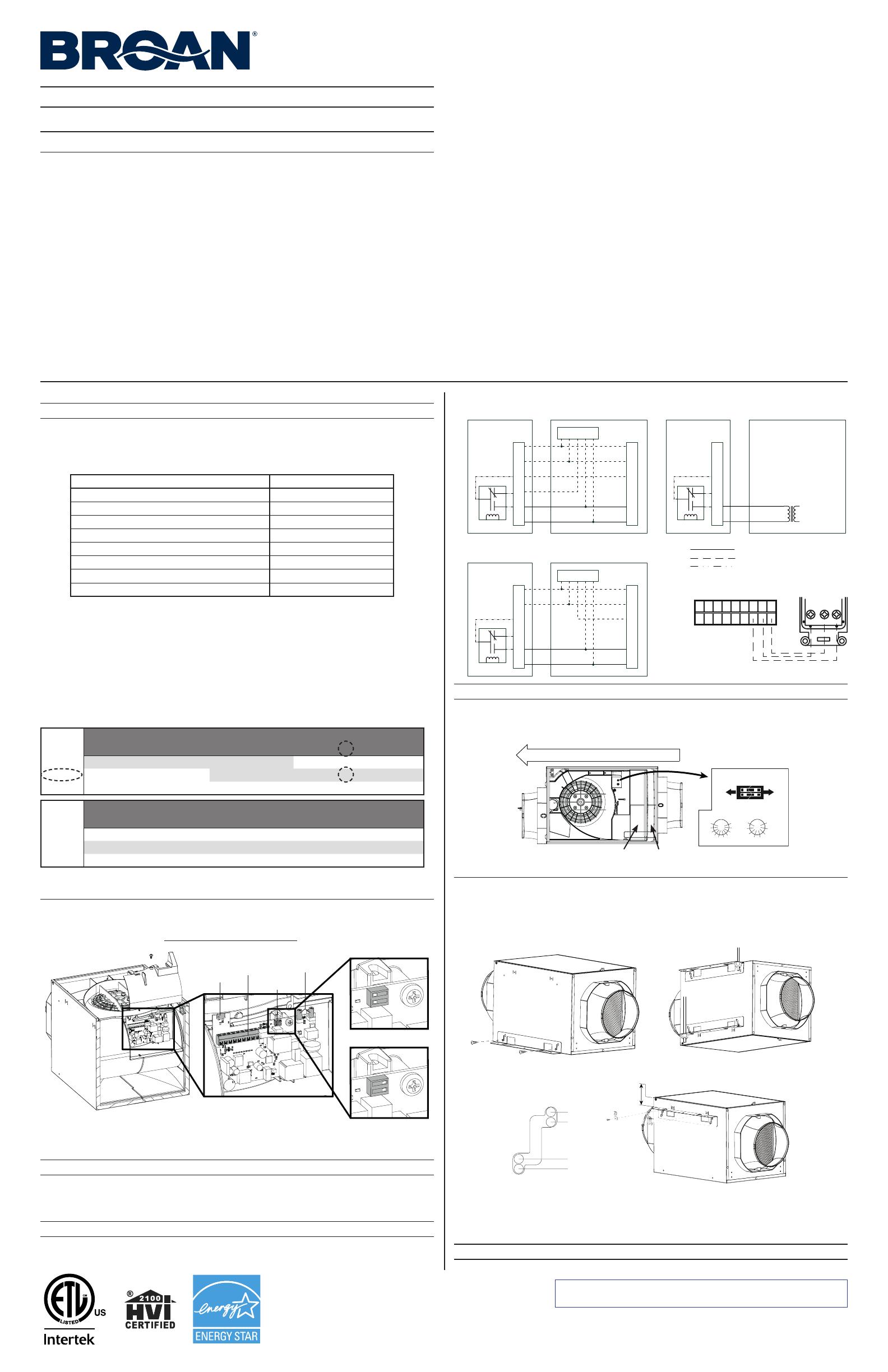
2. CONEXIÓN Y CONFIGURACIÓN DEL APARATO
1. Retire el tornillo que sujeta la tapa del compartimento eléctrico así como la tapa.
2. Establezca el interruptor de velocidad en 130 pi
3
/min o 180 pi³/min, según la configuración elegida
previamente. El aparato ha sido configurado en fábrica en 130 pi³/min.
3. Utilice el bloque de terminales situado en la tarjeta electrónica para realizar la conexión de baja tensión;
consulte la siguiente columna para los diagramas de cableado. Es obligatorio conectar el aparato a una
fuente de alimentación de baja tensión.
⚠ ADVERTENCIA
Riesgo de descarga eléctrica. El cableado eléctrico debe ser realizado por personal
cualificado, de acuerdo con todos los códigos y normas aplicables. Antes de conectar
los hilos, apague la alimentación en el tablero de servicio y bloquee los medios de
desconexión para evitar que se conecte la corriente accidentalmente.
PRECAUCIÓN
La interfaz de control de los sistemas AHU puede variar. Póngase en contacto con su
proveedor de la unidad de acondicionamiento del aire (AHU) para cualquier instalación
con especificaciones eléctricas de cableado distintas.
PRECAUCIÓN
Compruebe que ha vuelto a colocar en su sitio la espuma de sellado de los hilos.
Vuelva a instalar la tapa del compartimento eléctrico (asegúrese de no dejar pillados los cables) y configure
los botones de modo y de % de tiempo de funcionamiento, según la configuración elegida anteriormente.
No sincronizado: Venlador impelente de la unidad AHU no acvado
cuando está en marcha el venlador de alimentación
Y
W
G
F
G
R
C
COM
NC
NO
Sistema del
ventilador de
alimentación Y
W
G
R
C
Y W G R C
Termostato
Cableado de instalación opcional
Conexiones alámbricas del ventilador
de alimentación
AHU
J4
Cableado de instalación obligatoria
Sincronizado: Ponga en marcha el venlador impelente de la
unidad AHU cuando esté funcionando el venlador de alimentación
Y
W
G
F
G
R
C
COM
NC
NO
Sin conexión con la unidad AHU, alimentación autónoma
J4
120VCA
Transformador
de 24 VCA
Línea
Neutro
24VCA
Y
W
G
F
G
R
C
COM
NC
NO
Circuito lógico
interno
Y
W
G
R
C
Y W G R C
Termostato
AHU
J4
Sistema del
ventilador de
alimentación
Sistema del
ventilador de
alimentación
Circuito lógico
interno
Circuito lógico
interno
IOC
OL
YWGf GR C LED STB
IN
STB
out
VE0423E
COnTrOl mural OpCiOnal VT11W
Filtro MERV Filtro principal
VD0464
MODE
1
2
3
AB
C
D
E
on the electronic board
SPEED SWITCH
130
CFM
180
CFM
Test
20
30
40
5060
70
80
90
100
RUN
TIME %
DIRECCIÓN DE LA CORRIENTE DE AIRE
VD0468
3. INSTALE LOS SOPORTES SEGUN EL TIPO DE INSTALACIÓN
Instale los soportes en el aparato de una de las formas que se ilustran abajo, utilizando para ello 4 tornillos
n.º 8-18 x 0,375 pulg. NO UTILISE OTROS TORNILLOS.
💡 Para una instalación entre viguetas situadas a 16 o a 24 pulgadas de distancia, utilice el soporte opcional
FIN-S1624 (véanse las instrucciones que vienen con el soporte).
3A. en lA PAred, deBAjo el teCHo o en el desván 3B. ColgAdo del teCHo
3C. A rAs del teCHo
💡 Antes de pintar, limpie la carcasa metálica con un disolvente y el acabado decorativo de plástico con agua.
💡 Si el acabado se hace utilizando el acabado decorativo opcional (n.º de pieza FIN-R1015), los muelles
incluidos en el kit opcional deberán instalarse antes que los soportes.
X
VD0470
X = 5/8"
X = 1¼"
X = 1/2"
X = 1³/8"
poSición de loS tornilloS Según
el groSor del techo
PRECAUCIÓN
No instale el aparato en un desván donde la temperatura puede superar los 160°F.
VD0465
O
LEA Y GUARDE ESTAS INSTRUCCIONES
⚠ PARA USO RESIDENCIAL ÚNICAMENTE
Este manual utiliza los siguientes símbolos para hacer hincapié en determinada información:
ADVERTENCIA
Se refiere a una instrucción que, si no se sigue, puede provocar lesiones
personales graves, incluso causar la muerte.
PRECAUCIÓN
Denota una instrucción que, si no se sigue, puede dañar gravemente el aparato
y/o sus componentes.
💡Indica una información complementaria que puede referirse a piezas opcionales o simplemente
para facilitar una tarea.
⚠ ADVERTENCIA
PARA REDUCIR EL RIESGO DE INCENDIO, CHOQUE ELÉCTRICO O HERIDAS CORPORALES, SIGA
LAS INDICACIONES SIGUIENTES:
1. Utilice este aparato sólo en la forma prevista por el fabricante. Si tiene preguntas, póngase en contacto con el fabricante.
2. Antes de realizar tareas de mantenimiento o de limpiar el aparato, apague la alimentación en el tablero de
servicio.
3. Este aparato no ha sido pensado para proporcionar aire de combustión o de dilución para aparatos que
queman combustible.
4. No use el aparato con un dispositivo de control de velocidad de semiconductores diferente del que se indica
en la sección 2.
5. MODELO FIN-180P SOLAMENTE: No utilice un ventilador con un cable o enchufe dañado. Deseche el ventilador
o póngase en contacto con su contratista de calefacción, ventilación y aire acondicionado o con el fabricante.
6. MODELO FIN-180P SOLAMENTE: No haga pasar el cable por debajo de una alfombra o moqueta. No cubra
el cable con alfombrillas, tapetes u otros recubrimientos similares. No pase el cable por debajo de muebles o
electrodomésticos. Haga pasar el cable lejos de las zonas de circulación y donde nadie pueda tropezarse con él.
7. Los trabajos de instalación han de ser realizados por personas cualificadas, de conformidad con todos los
códigos y normas aplicables, incluyendo los relativos a la construcción contra incendios.
8. Al cortar o taladrar en una pared o en el techo, procure no dañar el cableado eléctrico ni otras instalaciones ocultas
.
9. TODOS LOS APARATOS:
Este aparato debe conectarse a tierra
. MODELO FIN-180P SOLAMENTE:
El
cable de alimentación lleva un enchufe con toma de tierra de 3 patillas para su seguridad personal. Debe enchufarse
en una toma de corriente para tres patillas, conectada a tierra de acuerdo con el código eléctrico nacional y los
códigos y ordenanzas locales. No retire la patilla de la toma de tierra. No utilice el aparato con un cable prolongador.
10. Durante el mantenimiento, limpieza e instalación de este aparato se aconseja llevar lentes y guantes de
seguridad.
11. Cuando la reglamentación local aplicable sea más restrictiva en materia de instalación o certificación, dicha
reglamentación prevalecerá sobre las exigencias de este manual y el instalador acepta atenerse a dicha
reglamentación y asumir los gastos correspondientes.
12. El aparato debe montarse al menos a 3,3 pies (1 metro) de distancia de cualquier abertura accesible del conducto.
PRECAUCIÓN
1. Para mayor información sobre otras exigencias, lea la etiqueta de especificaciones que viene en el aparato.
2. No introduzca el aire en espacios situados entre paredes, en el techo o en un desván, en sótanos pequeños
ni en cocheras. No intente recuperar el aire de salida de una secadora o de una campana ya que podría
obstruirse el módulo de recuperación.
3. Diseñado para instalaciones residenciales únicamente, de conformidad con los requisitos de la norma NFPA 90B.
4. Al ausentarse de la vivienda durante un periodo largo (más de dos semanas), una persona responsable debería
verificar regularmente si el aparato funciona correctamente.
5. Al menos una vez al año, personal de servicio cualificado debería examinar las piezas mecánicas y electrónicas
del aparato.
6. Dado que el sistema de control electrónico del aparato utiliza un microprocesador, es posible que no funcione
correctamente debido a los ruidos externos o a fallas de alimentación muy cortas. Si esto ocurre, desenchufe
el aparato y espere aproximadamente 10 segundos. A continuación, enchufe de nuevo el aparato.
7. La boca de admisión de aire exterior ha de ser a prueba de intemperie y llevar una tela metálica contra los pájaros.
8. Si decide deshacerse de este aparato o de partes de él, hágalo de conformidad con las leyes y reglamentos locales.
9. Algunas zonas son propensas a una mayor frecuencia de las subidas de tensión inducidas por los rayos. Se
aconseja usar un dispositivo protector contra las subidas de tensión para proteger los aparatos situados en
esas zonas.
VL0080
Sensor
Bloque de
terminales Interruptor
de velocidad
Configuración del
modo y tiempo de
funcionamiento
130 pi³/min (baja velocidad)
180 pi³/min (alta velocidad)
4
4. CONSIDERACIONES DEL INSTALADOR
PRECAUCIÓN
Utilice siempre conductos aislados con un factor de aislamiento mínimo R-4.
El instalador deberá asegurarse de que, de ser necesario, se instale un calentador en línea de un tamaño
acorde con la corriente de aire y con la temperatura de calentamiento del diseño exterior, según el Manual J
o la tabla ASHRAE, para que el aire suministrado a la unidad de acondicionamiento del aire no esté nunca por
debajo de la temperatura mínima permitida por el fabricante (en general, 55 °F). El calentador en línea tendrá
un sensor de la corriente de aire y un sensor de temperatura integrados para prevenir el calentamiento en
ausencia o con poca corriente.
A la hora de decidir si se necesita un precalentador y si se debe instalar ANTES o DESPUÉS del ventilador
de alimentación, tenga en cuenta los siguientes aspectos:
La temperatura de funcionamiento mínima
de este ventilador de alimentación es de 14°F.
La distancia mínima entre el precalentador y
ventilador de alimentación es de 12 pulgadas.
La temperatura distribuida en los
conductos no debe ser inferior a 55°F,
a menos que el ventilador de la unidad
de acondicionamiento del aire esté
funcionando constantemente.
5. CONEXIÓN DE LOS CONDUCTOS AISLADOS AL APARATO
1. Deslice el conducto flexible redondo interior de 6 pulg. sobre el puerto y átelo con una tira de amarre.
2. Tire del aislamiento y colóquelo sobre el anillo interior del puerto sin comprimirlo para reducir la formación
posible de condensación en el conducto y para reducir la pérdida y la ganancia de calor.
3. Utilice cinta adhesiva para sellar la membrana exterior del conducto aislado en el anillo exterior del
puerto y así formar una trayectoria hermética. Eso reducirá la pérdida y la ganancia de calor y reducirá
la posibilidad de condensación.
💡 Evite el bloqueo de los puertos de prueba con la cinta adhesiva.
Puertos de prueba
VJ0151
6. ALIMENTACIÓN DEL APARATO
6.1 Fin-180P
Conecte el cable de alimentación a una toma de corriente mural
para tres patillas
.
6.2 Fin-180P-HW
⚠ ADVERTENCIA
Riesgo de descarga eléctrica. El cableado eléctrico debe ser realizado por personal
cualificado, de acuerdo con todos los códigos y normas aplicables. Antes de conectar los
hilos, apague la alimentación en el tablero de servicio y bloquee los medios de desconexión
para evitar que se conecte la corriente accidentalmente.
NOTA: El conducto aislado y los hilos de baja tensión no se muestran para simplificar la ilustración de abajo.
1. Separe la cubierta del compartimento eléctrico del aparato retirando el tornillo de retención.
2. Instale en el aparato la abrazadera de cables. Inserte el cable de alimentación doméstica por la abrazadera
de cables y apriete la abrazadera para sujetar el cable.
3. Utilice los conectores de cables para conectar los cables de la siguiente manera: El NEGRO con el
NEGRO, el BLANCO con el BLANCO y el cable VERDE o PELADO bajo el tornillo de tierra VERDE.
NO OLVIDE LA CONEXIÓN A TIERRA.
4. Vuelva a poner en su lugar la cubierta del compartimento eléctrico procurando no aplastar los cables.
Restablezca la corriente en el tablero de servicio.
VE0424
Tornillo de tierra
7. COMO PROBAR EL APARATO
Una vez que se haya instalado el aparato, que se haya hecho la conexión de baja tensión, y que se hayan
instalado los conductos y las bocas, puede probarse la corriente de aire. Para hacerlo:
1. Abra la puerta del aparato y tome nota de la configuración del % de tiempo de funcionamiento del aparato.
2. Si se conecta a los conductos de una unidad AHU (unidad de acondicionamiento
del aire), apague dicha unidad al medir la corriente de aire.
3. Gire el botón de % de tiempo de funcionamiento hasta colocarlo en la
posición «Test» y cierre la puerta.
4. Espere a que haya terminado la secuencia de arranque
(al menos 45 segundos).
5. Retire el tapón del puerto de prueba en el lado de la admisión de aire del
aparato.
6. Pruebe la corriente de aire mediante un tubo Pitot. La distancia entre el
puerto de prueba y el centro del conducto es de 3,75 pulgadas.
7. Vuelva a colocar el tapón en el puerto de prueba.
8. Vuelva a colocar el botón de % de tiempo de funcionamiento en su
configuración anterior.
NOTA: Para forzar la clausura de la compuerta, desenchufe el cable de alimentación o apague la
alimentación en el tablero de servicio. La baja tensión (24VCA) debe permanecer conectada para
permitir el funcionamiento de la compuerta.
8. CABLEADO
DIAGRAMA LÓGICO
DIAGRAMA DE CABLEADOS
Ref: 99046031_REV-B
VE0420E
K1
M1
Fuente de
alimentación
(12 V)
Línea
Neutro
(24VCA)
K2
R
C
G
Gf
PTC
Filtro
de línea
de CA
J1-2
J4-7
J4-6
J4-4
J4-5
F1
Alta tensión
Baja tensión
(120VCA)
J1-1
Hacia J10
J2-1
J2-2
MCU
K1
K2
M2
Motor de
velocidad
gradual
J5-1,2,3,4
Cableado de fábrica de tensión de línea
Cableado de fábrica de baja tensión
Cableado in situ de baja tensión
NE Motor del
venlador de
alimentación
NA
AZ
RO
BL
Cable de alimentación
1
1
1
F1
J10
J2
J1
11
J7 J9
1
J5
BDM
1
LED 1
(baja potencia)
LED 2
(Estado)
LED 3
(120 VCA)
1
J4
19
M2
RO
AZ
AM
RA
Mazo de cables
del motor de la
compuerta
Y
W
Gf
G
R
C
Control Mural
VT11W (opcional)
Salida
en espera
Entrada
en espera
LED Alimentación
+24VAC
Cableado de
AHU (opcional)
Cable de control
M1
VE
BL
NE
A1
CONJUNTO ELECTRÓNICO
Sensor RH
Selección
de modo
Selección
de gama
de pi
3
/min
Selección
de la
velocidad
Fuente de
alimentación
(3.3 V)
CÓDIGO DE COLORES CABLEADO
NE NEGRO
VE VERDE
RA ROSA
RO ROJO
AZ AZUL
NA NARANJA
BL BLANCO
AM AMARILLO
VE
BL
NE
120 VCA,
60 Hz
Línea
Neutro
Tierra
120 VCA,
60 Hz
W1
VE
BL
NE
FIN-180P
FIN-180P-HW
9. INFORMACIÓN DEL USUARIO
9.1 Control MUrAl oPCionAl
Este aparato puede conectarse a un control mural VT11W.
Tras el inicio, el LED del control mural se encenderá durante la secuencia de arranque y permanecerá
encendido cuando el aparato empiece a funcionar después de la secuencia de arranque. Presione el
botón pulsador para apagar el aparato; el LED del control mural también se apagará.
Cuando llegue el momento de realizar el mantenimiento del filtro, el LED del control mural parpadeará
lentamente (2 segundos encendido, 2 segundos apagado). Una vez realizadas las tareas de
mantenimiento, presione y mantenga presionado el botón pulsador durante 5 segundos para reiniciar el
recordatorio de mantenimiento del filtro.
Consulte a su instalador si se produce otro tipo de parpadeo.
9.2 instrUCCiones de MAnteniMiento PArA el UsUArio
El filtro metálico que viene con este aparato debe limpiarse cada 6 meses con agua y un jabón suave.
Para retirar el o los filtros, abra la puerta, suelte el clip que sujeta el filtro y saque el filtro. Deje secar el
filtro completamente antes de volver a colocarlo en el aparato; cuando se vuelva a colocar en el aparato,
asegúrese de que esté derecho.
Examine la admisión de aire exterior al menos una vez al año.
Durante el primer año de funcionamiento se aconseja examinar el aparato con mayor frecuencia,
especialmente si vive cerca de una autopista o en una zona donde hay muchas obras de construcción,
que generan mucho polvo. En tales condiciones, puede que sea necesario limpiar o cambiar los filtros
con mayor frecuencia.
Sustituya los filtros opcionales MERV al menos una vez al año; no trate de limpiarlos y reutilizarlos.
Estas recomendaciones pueden cambiar según las condiciones ambientales de su zona.
9.3 Modo ConFort
Si el aire dentro de su casa es demasiado húmedo o si se quiere prevenir tales condiciones, se puede cambiar
el modo de funcionamiento del ventilador de alimentación y pasar de un modo conforme con el código (modos
1 a 3) a un modo de confort (modos A a E). Consulte el mapa abajo para acertar en la selección.
Al realizar este cambio, asegúrese de que sólo cambia el modo y deje el % de tiempo de funcionamiento como
lo configuró el instalador. En caso de duda, consulte a su contratista de climatización.
Modo seleccionado Zonas climáticas*
1 - Ashrae 2016 Zonas 1-4
2 - Ashrae 2010 (configuración de fábrica) Zonas 1-4
3 - IRC / IMC 2012-2015 Zonas 1-4
A - Modo confort caliente/húmedo #1 Zonas 2A y 1
B - Modo confort caliente/húmedo #2 Zonas 1 y 2A
C - Modo confort caliente/seco Zona 2B
D - Modo confort mixto/húmedo Zonas 3A, 4A, 3C y 4C
E - Modo confort mixto/seco Zonas 3B y 4B
*Según lo definido por el Departamento de Energía. Consulte el mapa abajo.
Marino (C) Seco (B) Húmedo (A)
(Incl. Hawái)
VN0011E
*No recomendado en
todas las demás zonas.
VD0472
Puertos de prueba
Agujero de los hilos de baja tensión
solamente (hilos no se muestran)
IMPORTANTE - Los conductos desde este ventilador hacia el exterior del edificio tienen un gran efecto
sobre el flujo de aire, el ruido y el uso de energía del ventilador. Utilice el tramo de conductos más corto y
recto posible para obtener un desempeño óptimo y evite instalar el ventilador con conductos menores que
los recomendados. El aislamiento alrededor de los conductos puede reducir la pérdida de energía e inhibir el
desarrollo de moho. Los ventiladores instalados en conductos existentes podrían no obtener el flujo de aire
nominal.
PRECAUCIÓN
Compruebe que el aislamiento esté reemplazado alrededor de cualquier abertura que se deba practicar
para la instalación del aparato o del conducto. Sellar el aislamiento con cinta adhesiva o masilla para
reducir la pérdida y la ganancia de calor del edificio y para reducir la posibilidad de condensación.
ADVERTENCIA
Compruebe que la boca de admisión de aire exterior esté al menos a 12 pulgadas por
encima del suelo y a 6 pies de distancia de cualquiera de los siguientes elementos: Salida
de aire de una secadora, abertura de caldera de alto rendimiento, abertura de aspirador
central, abertura de contador de gas, parrilla o barbacoa de gas, cualquier abertura de una
fuente de combustión, cubo de basura u otra fuente de contaminación.
💡 Asegúrese de que se pueda acceder fácilmente a la boca de admisión de aire exterior para el mantenimiento
anual. Si se encuentra por encima de la primera planta, colóquela cerca de una ventana o balcón para
facilitar el acceso.
  • Page 1 1
  • Page 2 2
  • Page 3 3
  • Page 4 4

Broan FIN-180P Manual de usuario

Tipo
Manual de usuario

El Broan FIN-180P es un ventilador de suministro de aire fresco que puede usarse en una variedad de aplicaciones residenciales, incluyendo paredes, techos abuhardillados o áticos. Está diseñado para proporcionar una ventilación adecuada en hogares y oficinas, y puede ayudar a mejorar la calidad del aire interior al introducir aire fresco y eliminar contaminantes. Es relativamente fácil de instalar y se puede usar para reemplazar un ventilador de ventilación existente para proveer más flujo de aire.

En otros idiomas