
KOS1600BA
20221007
DISEÑOS Y TECNOLOGÍA, S.A.
Xarol, 6B P.I. Les Guixeres
08915 Badalona (Barcelona) - Spain
Tel. +34 933 394 758
Fax +34 934 903 145
Email: comercial@ditel.es ; web: www.ditel.es
ESPAÑOL
CONVERTIDOR DE CÉLULAS DE CARGA
FRANÇAIS
CONVERTISSEUR DE CELLULE DE CHARGE
ENGLISH
LOAD CELL CONVERTER
GUIA RÁPIDA DE INSTALACIÓN .............................................. 02/03
GUIDE D'INSTALLATION RAPIDE ............................................. 04/05
QUICK INSTALLATION GUIDE ..................................................06/07
DOWNLOAD
USER MANUAL

2
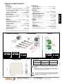
RANGOS DE GANANCIA Y TARA CONFIGURABLES
MULTIESCALA CON ESCALONES DE ALTA PRECISIÓN
TARA CONFIGURABLE (SUMAR / RESTAR)
SALIDA MÚLTIPLE AISLADA (0/4-20mA, 0-10V, ±10V)
ALIMENTACIÓN AISLADA 24 VDC
EXCITACIÓN CÉLULAS 10/5V @ 120mA
DESCRIPCIÓN
Convertidor aislador universal para células de carga y captadores en puente de Wheastone.
Suministra una señal de salida, múltiple de tensión e intensidad aislada y proporcional a la fuerza/peso del sensor.
Se pueden introducir de 1 a 4 células de carga con excitación protegida ante cortocircuitos permanentemente.
Dispone de alimentación aislada 24VDC (20.. 30V) con amplio margen.
La alimentación al módulo así como la excitación a la célula se supervisa mediante la señalización del led frontal OK.
Admite, automáticamente, células tracción/compresión (salida 12±8mA, 0/±10V).
Permite absorber (restar) o sumar con gran precisión y estabilidad un amplio rango de tara.
Dispone de un filtro seleccionable en 4 niveles para estabilizar la señal de salida dependiendo de cada aplicación.
Todos estos parámetros se configuran fácilmente en el frontal, quedando protegidos por una tapa abatible.
Está protegido cumpliendo normas EMC para aplicaciones industriales.
La conexión se realiza mediante bornas enchufables, facilitan el rápido intercambio de módulos sin necesidad de volver a cablear.
DATA SHEET — GUIA RÁPIDA DE INSTALACIÓN
CONVERTIDOR DE CÉLULAS DE CARGA
KOS1600BA
CONFIGURACIONES (frontal)
(Estándar 2mV/V<>4-20mA + 0-10V)
CONFIGURACIÓN SENSIBILIDAD DE CÉLULA
CÉLULA PATRÓN
ACCESO A CONFIGURACIONES
TARA
SUMAR
RESTAR
AJUSTES DE ESCALA
INICIO = CERO
FINAL = SPAN
El ajuste de CERO y SPAN
se realiza en 3 pasos:
1– SELECCIÓN GAMA (x1 o x2)
2- AJUSTE GRUESO
3– AJUSTE FINO
Mediante la suma de las ponde-
raciones de 3 soldaduras (+0.8)
se selecciona la sensibilidad más
aproximada de la célula.
OFF ponderación seleccionada
ON ponderación no seleccionada
Aunque con el SPAN del frontal se dispone de un
amplio margen de ajuste de sensibilidad de célula,
para obtener la máxima precisión, conviene para-
metrizar las soldaduras al valor más cercano.
EXCITACIÓN CÉLULA
Mediante un puente (STRAP) se
selecciona la tensión de excitación
a célula (10V por defecto).
Dispone internamente de célula patrón para pruebas.
Desconectar la célula para simular una célula con peso F.E.
(fondo de escala) y peso 0 (cero).
EJEMPLO : Célula 2mV/V, Tara 20%, Salida 0-10V
Conectar la alimentación y los instrumentos de medida.
Conectar el generador de mV a la entrada del convertidor con el accesorio de célula de carga. En el
caso de no tener accesorio, conectar una resistencia de 10K entre la entrada (-mV) y (-) .
Antes de proceder al ajuste, mantenerlo previamente al menos 15 minutos, para que se estabilicen
térmicamente el convertidor y el instrumento de medida.
Medir la tensión de excitación a la célula.
Generar las tensiones de calibración teniendo en cuenta la sensibilidad de la célula y la tensión de
excitación.
Seleccionar, con el generador de mV, el valor de inicio de escala deseado.
Inicio= Vexc . mV/V . %TARA
Ajustar el inicio de escala de salida V ó I.
1. Empezar seleccionando la gama de CERO con el microswitch en x1.
Usar x2 sólo en el caso de que no llegue la salida con grueso y fino a tope.
2. Girar el microswitch rotativo de CERO, seleccionando el valor más próximo.
3. Ajustar al valor exacto con el potenciómetro de CERO fino.
Seleccionar con el generador de mV, el valor de final de escala deseada.
Final escala= Vexc . mV/V
Ajustar el final de escala de salida V ó I.
1. Empezar seleccionando la gama del final de escala con el microswitch en x1. Usar x2
sólo en el caso de que no llegue la salida con grueso y fino a tope.
2. Girar el microswitch rotativo de SPAN, seleccionando el valor más próximo.
3. Ajustar al valor exacto con el potenciómetro de SPAN fino.
Volver a ajustar el inicio y final de escala, retocando sólo los ajustables de
fino, hasta conseguir en la salida la escala deseada
.
CALIBRACIÓN CON GENERADOR DE mV

3
20221007
DISEÑOS Y TECNOLOGÍA, S.A.
Xarol, 6B P.I. Les Guixeres
08915 Badalona (Barcelona) - Spain
Tel. +34 933 394 758
Fax +34 934 903 145
Email: comercial@ditel.es ; web: www.ditel.es
ESPECIFICACIONES TÉCNICAS
ENTRADAS
Célula de carga
1 .. 4 Células…...…………………………………………………...350Ω/4
Sensibilidad..…(seleccionable internamente) …..0.8 a 3 mV/V
Tensión de excitación…(seleccionable por jumper)…10/5 VDC
Corriente de excitación máxima …………………………...120 mA
Chequeo excitación correcta …………….…………….led verde OK
Excitación cortocircuitable..……………………. Permanentemente
Patrón célula TEST
Selección célula patrón incorporada….……….. por microswitch
Patrón fondo escala (F.E.) célula ….………………………….20 mV
Patrón peso cero ……………………………………………………0 mV
SALIDA
Intensidad..….………………….… (0-20mA / 4-20mA / 0-5mA)
Capacidad de carga máxima ……….....………………………≤700Ω
Protegida contra inversión de polaridad
Tiempo de respuesta* …………………………………….. 0.02 a 0.5s
Frecuencia de corte ……………………………………….. 18 a 0.7 Hz
Tensión ………...……………………………….(0-10V / ±10v / 0-5V)
Capacidad de carga máxima….………………………………... ≥ 1kΩ
Protegida contra cortocircuito
Tiempo de respuesta* .…………………………………. 0.001 a 0.5s
Frecuencia de corte ………………………………………..350 a 0.7 Hz
*Tiempos de respuesta seleccionables en el frontal….4 niveles
ALIMENTACIÓN
Tensión de alimentación………….……………...24 VDC (20 a 30V)
Consumo máximo ….………………………………………………… 1.8W
Aislamiento galvánico.……………………………………………..1500 V
PRECISIÓN
Máximo error global ……………………………………(14bits) 0.01%
Deriva térmica ..….…...……………I: 0.3uA/ºC / V: 0.1mV/ºC
CONDICIONES AMBIENTALES
Temperatura trabajo …………………………………. -10ºC ÷ +60ºC
Temperatura almacenamiento …………………. -40ºC ÷ +80ºC
Tiempo de calentamiento ..……………………………….. 5 minutos
Coeficiente de temperatura …………………………... 50ppm / ºC
FORMATO
Protección …………………………………………………………….. IP20
Material ………………………….………………………...Poliamida PA6.6
Peso .…..……………………………………….……………………………100g
Combustibilidad según UL …………………………………………...V0
Montaje ………………………………………………………. rail EN50022
CONEXIONES
Bornes por tornillo M3 ……………………….. par de apriete 0.5Nm
Cable de conexión ………………………………….≤2.5mm² (12AWG)
Protección equivocación de bornas ……………….… codificadores
DIMENSIONES
CONEXIONADO
Directivas EMC 2014/30/EU LVD 2014/35/EU
Normas EN 61000-6-2
EN 61000-6-3 EN 61010-1
Conformidad CE .
ATENCIÓN: Si este instrumento no se instala y utiliza de acuerdo con estas
instrucciones, la protección que brinda contra riesgos puede verse
afectada
Para cumplir con los requisitos de la norma EN 61010-1, donde la unidad está
permanentemente conectada a la fuente de alimentación principal, es obligatorio
instalar un dispositivo de corte de circuito fácilmente accesible para el operador y
claramente marcado como dispositivo de desconexión.
De acuerdo con la Directiva 2012/19 / UE, no puede desecharlo al final
de su vida útil como basura municipal sin clasificar. Puede devolverlo,
sin ningún costo, al lugar donde fue adquirido para proceder a su
tratamiento y reciclaje controlados.
SALIDA 4-20mA
ACTIVA
PIN 7 LIBRE
PIN 8 +mA
PIN 9 - mA
SALIDA 0-10V /
±10V
PIN 4 LIBRE
PIN 5 - V
PIN 6 +V
ALIMENTACIÓN
PIN 10 VDC (+)
PIN 11 LIBRE
PIN 12 VDC (-)
CÉLULAS DE CARGA SALIDA
ENTRADA
KOS1600BA
PIN 0 +mV
PIN 1 - mV
PIN 2 +EXC
PIN 3 - EXC
SALIDA CÉLULAS
DE CARGA
PIN 0 +OUT
PIN 1 - OUT
PIN 2 +IN
PIN 3 - IN
ESPAÑOL

4
PLAGES DE GAIN ET DE TARE CONFIGURABLES
MULTI-ÉCHELLE AVEC DES ÉTAPES DE HAUTE PRÉCISION
TARE CONFIGURABLE (AJOUTER / SOUSTRAIRE)
SORTIE MULTIPLE ISOLEE (0/4-20mA, 0-10V, ±10V)
ALIMENTATION ISOLEE 24 VDC
EXCITATION DES CELLULES 10/5V @ 120mA
DESCRIPTION
Convertisseur d'isolement universel pour cellules de charge et capteurs de pont de Wheastone.
Il fournit un signal de sortie, multiple de tension et d'intensité isolé et proportionnel à la force/poids du capteur.
Vous pouvez saisir de 1 à 4 capteurs de pesage à excitation protégés contre les courts-circuits en permanence.
Il dispose d'une alimentation isolée 24VDC (20.. 30V).
L'alimentation du module ainsi que l'excitation de la cellule sont supervisées par la signalisation de la LED frontale OK.
Admet automatiquement les cellules de tension/compression (sortie 12±8mA, 0/±10V).
Il permet d'absorber (soustraire) ou d'ajouter une large plage de tare avec une grande précision et stabilité.
Il dispose d'un filtre sélectionnable sur 4 niveaux pour stabiliser le signal de sortie en fonction de chaque application.
Tous ces paramètres sont facilement configurables à l'avant, étant protégés par un couvercle à charnière.
Il est protégé en respectant les normes CEM pour les applications industrielles.
Le raccordement s'effectue par bornes débrochables, elles facilitent l'échange rapide des modules sans nécessiter de recâblage.
DATA SHEET — GUIDE D'INSTALLATION RAPIDE
CONVERTISSEUR DE CELLULE DE CHARGE
KOS1600BA
CONFIGURATIONS (face avant)
(Standard 2mV/V<>4-20mA + 0-10V)
CONFIGURATION DE LA SENSIBILITÉ DE LA CELLULE
CELLULE MAÎTRE TEST
ACCÈS AUX CONFIGURATIONS INTERNES
TARE
AJOUTER
SOUSTRAIRE
RÉGLAGES D'ÉCHELLE
DÉBUT = ZÉRO
FIN = SPAN
Réglage ZERO et SPAN
Il se fait en 3 étapes :
1– SÉLECTION DE GAMME (x1 ou x2)
2- AJUSTEMENT GROSSIER
3– AJUSTEMENT FIN
En additionnant les poids de 3
soudures (+0,8) la sensibilité la
plus approximative de la cellule est
sélectionnée.
Pondération OFF sélectionnée
Pondération ON non sélectionnée
Bien qu'avec le SPAN du front il y ait une large
marge de réglage de la sensibilité de la cellule, pour
obtenir une précision maximale, il est conseillé de
paramétrer les soudures à la valeur la plus proche.
EXCITATION DE LA CELLULE
Au moyen d'un cavalier (STRAP) la
tension d'excitation de la cellule est
sélectionnée (10V par défaut).
Il a une cellule maître en interne pour les tests.
Déconnectez la cellule pour simuler une cellule de poids F.E. (pleine
échelle) et Poids 0.
EXEMPLE : Cellule 2mV/V, Tare 20%, Sortie 0-10V
Connecter l'alimentation et les instruments de mesure.
Connectez le générateur de mV à l'entrée du convertisseur avec l'accessoire cellule de charge. Si
vous n'avez pas d'accessoire, connectez une résistance de 10K entre l'entrée (-mV) et (-).
Avant de procéder au réglage, attendre pendant au moins 15 minutes, afin que le convertisseur et
l'instrument de mesure soient thermiquement stabilisés.
Mesurer la tension d'excitation à la cellule.
Générer les tensions d'étalonnage en tenant compte de la sensibilité de la cellule et de la tension
d'excitation.
Sélectionner, avec le générateur de mV, la valeur de début d'échelle souhaitée.
Début= Vexc . mV/V . %TARE
Réglez le début de la sortie d'échelle V ou I.
1. Commencez par sélectionner la gamme ZERO avec le micro-interrupteur en x1.
Utilisez x2 uniquement dans le cas où la sortie n'arrive pas avec grossier et fin en haut.
2. Tourner le micro-interrupteur rotatif ZERO en sélectionnant la valeur la plus proche.
3. Ajuster à la valeur exacte avec le potentiomètre ZERO fin.
À l'aide du générateur de mV, sélectionnez la valeur de fin d'échelle souhaitée.
Fin d'échelle= Vexc . mV/V
Réglez l'extrémité de sortie de l'échelle V ou I.
1. Commencez par sélectionner la fin de gamme avec le micro-interrupteur en x1.
Utilisez x2 uniquement dans le cas où la sortie n'arrive pas avec grossier et fin en haut.
2. Tourner le micro-interrupteur rotatif SPAN en sélectionnant la valeur la plus proche.
3. Réglez à la valeur exacte avec le potentiomètre fin SPAN.
Réajustez le début et la fin de l'échelle, en ajustant uniquement ceux réglables de
fin, jusqu'à ce que l'échelle souhaitée soit obtenue dans la sortie.
ÉTALONNAGE AVEC GÉNÉRATEUR mV

5
20221007
DISEÑOS Y TECNOLOGÍA, S.A.
Xarol, 6B P.I. Les Guixeres
08915 Badalona (Barcelona) - Spain
Tel. +34 933 394 758
Fax +34 934 903 145
Email: comercial@ditel.es ; web: www.ditel.es
SPÉCIFICATIONS TECHNIQUES
ENTRÉES
Cellule de charge
1 .. 4 Cellules .....………………………………………………..350Ω/4
Sensibilité (sélectionnable en interne) …………..0.8 a 3 mV/V
Tension d'excitation (sélectionnable par cavalier) …10/5 VDC
Courant d'excitation maximal .….…………………………..120 mA
Vérification correcte de l'excitation …….……………led vert OK
Excitation court-circuitable .…………………… en permanence
Cellule maître TEST
Sélection de cellule maître intégrée….………. par microswitch
Valeur pleine échelle (F.S.) de la cellule …………………20 mV
Valeu de poids zero de la cellule …………………………… 0 mV
SORTIES
Courant ..….………………….…(0-20mA / 4-20mA / 0-5mA)
Capacité de charge maximale …….....………………………≤700Ω
Protégé contre l'inversion de polarité
Temps de réponse* …………………………………….. 0.02 a 0.5s
Fréquence de coupure ………………………………….. 18 a 0.7 Hz
Tension ………..……………………………….(0-10V / ±10v / 0-5V)
Capacité de charge maximale ………………………………... ≥ 1kΩ
Protégé contre l'inversion de polarité
Temps de réponse* ..…………………………………. 0.001 a 0.5s
Fréquence de coupure ..………………………………..350 a 0.7 Hz
*Temps de réponse sélectionnables ………………...….4 niveaux
ALIMENTATION
Tension d’alimentation .………….……………...24 VDC (20 à 30V)
Consommation maximale ………………………………………… 1.8W
Isolation galvanique .……………………………………………..1500 V
PRÉCISION
Erreur maximale globale …………………………… (14bits) 0.01%
Dérive thermique..….…...……………I: 0.3uA/ºC / V: 0.1mV/ºC
ENVIRONNEMENT
Température fonctionnement ……………………. -10ºC à +60ºC
Température de stockage ……….…………………. -40ºC à +80ºC
Temps de chauffage ……....……………………………….. 5 minutes
Coéfficent de température ….…………………………... 50ppm / ºC
FORMAT
Protection …………………………………………………………….. IP20
Materiel ..……………………….………………………...Poliamida PA6.6
Poids ....……………………………………….……………………………100g
Combustibilité selon UL ………….…………………………………...V0
Montage .……………………………………………………. rail EN50022
CONNEXIONS
Bornes à vis M3 ……………….……………………….. Torque 0.5Nm
Câble de connexion ……………………………….≤2.5mm² (12AWG)
Protection contre les erreurs de borne ………….… codificateurs
DIMENSIONS
RACCORDEMENT
SORTIE 4-20mA
ACTIVE
PIN 7 LIBRE
PIN 8 +mA
PIN 9 - mA
SORTIE 0-10V /
±10V
PIN 4 LIBRE
PIN 5 - V
PIN 6 +V
ALIMENTATION
PIN 10 VDC (+)
PIN 11 LIBRE
PIN 12 VDC (-)
CELLULE DE CHARGE SORTIE
ENTRÉE
KOS1600BA
PIN 0 +mV
PIN 1 - mV
PIN 2 +EXC
PIN 3 - EXC
SORTIE CELLULE
DE CHARGE
PIN 0 +OUT
PIN 1 - OUT
PIN 2 +IN
PIN 3 - IN
Directives EMC 2014/30/EU LVD 2014/35/EU
Normes EN 61000-6-2
EN 61000-6-3 EN 61010-1
Conformité CE .
ATTENTION : Si cet instrument n'est pas installé et utilisé conformément à
ces instructions, la protection qu'il offre contre les dangers peut être
altérée.
Pour répondre aux exigences de la norme EN 61010-1, où l'unité est connectée en
permanence à l'alimentation principale, il est obligatoire d'installer un dispositif de
coupure facilement accessible à l'opérateur et clairement identifié comme un
dispositif de déconnexion.
Selon la Directive 2012/19/UE, l’utilisateur ne pout se défaire de cet
appareil comme d’un residu urbain courant. Vous pouvez le restituer,
sans aucun coût, au lieu où il a eté acquis afin qu’il soit procédé à son
traitement et recyclage contrôlés.
FRANÇAIS

6
CONFIGURABLE GAIN AND TARE RANGES
MULTI-SCALE WITH HIGH PRECISION STEPS
CONFIGURABLE TARE (ADD / SUBTRACT)
ISOLATED MULTIPLE OUTPUT (0/4-20mA, 0-10V, ±10V)
ISOLATED POWER SUPPLY 24 VDC
CELLS EXCITATION 10/5V @ 120mA
DESCRIPTION
Universal isolating converter for Wheastone bridge load cells and sensors.
It comes with an isolated voltaje and current output proportional to the force/weight of the sensor.
You can enter from 1 to 4 load cells with excitation protected against short circuits permanently.
It has an isolated 24VDC (20.. 30V) power supply with a wide margin.
Device power supply and cell excitation is monitored via the OK led located at the front panel.
Traction/compression cells admitted automaticaly (output 12±8mA, 0/±10V).
It allows absorbing (subtracting) or adding a wide tare range with great precision and stability.
It has a selectable 4 levels filter to stabilize the output signal depending on each application.
All these parameters are easily configured on the front, being protected by a hinged cover.
It is protected by complying with EMC standards for industrial applications.
Wiring is achieved using pluggable terminals that facilitate a quick unit replacement without the need for rewiring.
DATA SHEET — QUICK INSTALLATION GUIDE
LOAD CELL CONVERTER
KOS1600BA
CONFIGURATIONS (front)
(Estándar 2mV/V<>4-20mA + 0-10V)
CELL SENSITIVITY SETTINGS
PATTERN CELL
ACCES TO INTERNAL SETTINGS
TARE
ADD
SUBTRACT
SCALE ADJUSTMENTS
START = ZERO
END = SPAN
ZERO and SPAN adjustment
It is done in 3 steps:
1– RANGE SELECTION (x1 or x2)
2- COARSE ADJUSTMENT
3– FINE ADJUSTMENT
By adding the weighting of 3
welds (+0.8) the most approxima-
te sensitivity of the cell is selected.
OFF weighting selected
ON weighting not selected
Although with the SPAN of the front there is a
wide margin of adjustment of cell sensitivity, to
obtain maximum precision, it is advisable to para-
meterize the welds to the closest value.
LOAD CELL EXCITATION
By means of a jumper (STRAP) the
cell excitation voltage is selected
(10V by default).
It has a pattern cell internally for tests.
Disconnect the cell to simulate a cell with weight F.S. (full sca-
le) and Weight 0 (zero).
EXAMPLE : Cell 2mV/V, Tare 20%, Output 0-10V
Connect the power supply and the measuring instruments.
Connect the mV generator to the input of the converter with the load cell accessory. If you don't
have an accessory, connect a 10K resistor between the (-mV) and (-) inputs.
Before proceeding with the adjustment, wait for at least 15 minutes, so that the converter and the
measuring instrument are thermally stabilized.
Measure the excitation voltage to the cell.
Generate the calibration voltages taking into account the sensitivity of the cell and the excitation
voltage.
Select, with the mV generator, the desired start of scale value.
Start= Vexc . mV/V . %TARE
Adjust the start of scale output V or I.
1. Start by selecting the ZERO range with the microswitch at x1.
Use x2 only in the case that the output does not arrive with coarse and fine at the top.
2. Turn the ZERO rotary microswitch, selecting the closest value.
3. Adjust to the exact value with the fine ZERO potentiometer.
Using the mV generator, select the desired end-of-scale value.
End of scale= Vexc. mV/V
Adjust the output end of scale V or I.
1. Start by selecting the end of scale range with the microswitch at x1. Use x2 only in the case
that the output does not arrive with coarse and fine at the top.
2. Turn the SPAN rotary microswitch, selecting the closest value.
3. Adjust to the exact value with the fine SPAN potentiometer.
Re-adjust the start and end of the scale, using only the adjustable ones of fine,
until the desired scale is obtained in the output.
CALIBRATION WITH mV GENERATOR

7
20221007
DISEÑOS Y TECNOLOGÍA, S.A.
Xarol, 6B P.I. Les Guixeres
08915 Badalona (Barcelona) - Spain
Tel. +34 933 394 758
Fax +34 934 903 145
Email: comercial@ditel.es ; web: www.ditel.es
TECHNICAL SPECIFICATIONS
INPUTS
Load Cell
1 .. 4 Cells ...…………………………………………………...350Ω/4
Sensibility..…(internally selectable) ……....…..0.8 to 3 mV/V
Excitation voltage…(selectable by jumper) ……...…10/5 VDC
Maximum excitation current ..…………………………...120 mA
Correct excitation check ..…………….……………. OK green LED
Short-circuitable excitation .…...……………………. Permanently
TEST pattern cell
Built-in pattern cell selection ……….………….. by microswitch
Full scale pattern cell (F.S.) ….….………………………….20 mV
Zero weight pattern ………………………………………………0 mV
OUTPUT
Current ……….………………….… (0-20mA / 4-20mA / 0-5mA)
Maximum load capacity …...……….....………………………≤700Ω
Protected against reverse polarity
Response time* ..…….………………………………….. 0.02 to 0.5s
Cutoff frequency …..…………………………………….. 18 to 0.7 Hz
Voltage .……...……………………………….(0-10V / ±10v / 0-5V)
Maximum load capacity ……..………………………………... ≥ 1kΩ
Short circuit protected
Response time* ……...…………………………………. 0.001 to 0.5s
Cutoff frequency …..……………………………………..350 to 0.7 Hz
*Selectable response times on the front panel ..…..….4 levels
POWER SUPPLY
Supply Voltage ………...………….……………...24 VDC (20 to 30V)
Maximum consumption …………………………………………… 1.8W
Galvanic isolation …..……………………………………………..1500 V
ACCURACY
Overall maximum error ………………………………(14bits) 0.01%
Thermal drift .....….…...……………I: 0.3uA/ºC / V: 0.1mV/ºC
ENVIRONMENTAL CONDITIONS
Operating temperature .……………………………. –10ºC to +600ºC
Storage temperatura ..….……………………………….-40ºC to +80ºC
Warm-up time ………...…...………………………………….. 5 minutes
Temperature coefficient .…………………………………... 50ppm / ºC
FORMAT
Protection ..………………………………………………………………... IP20
Material …………………………………………………...Polyamide PA6.6
Weight ………………………………………………………………………100g
UL Combustibility ..…………………………………………………………..V0
Mounting ..………………………………………………………..rail EN50022
WIRING
Screw terminals M3 ..……...……………………………... torque 0.5Nm
Connection cable ……………………………………..≤2.5mm² (12AWG)
Protection against mistakes …………………………...coded terminals
DIMENSIONS
WIRING
4-20mA OUTPUT
SOURCE
PIN 7 N.C.
PIN 8 +mA
PIN 9 - mA
0-10V / ±10V
OUTPUT
PIN 4 N.C.
PIN 5 - V
PIN 6 +V
POWER SUPPLY
PIN 10 VDC (+)
PIN 11 N.C.
PIN 12 VDC (-)
LOAD CELLS OUTPUT
KOS1600BA
INPUT
PIN 0 +mV
PIN 1 - mV
PIN 2 +EXC
PIN 3 - EXC
LOAD CELLS
OUTPUT
PIN 0 +OUT
PIN 1 - OUT
PIN 2 +IN
PIN 3 - IN
Directives EMC 2014/30/EU LVD 2014/35/EU
Standarts EN 61000-6-2
EN 61000-6-3 EN 61010-1
CE Conformity.
ATTENTION: If this instrument is not installed and used in accordance with
these instructions, the protection it provides against hazards may be
impaired.
To meet the requirements of EN 61010-1, where the unit is permanently connected
to the main power supply, it is mandatory to install a circuit-breaking device easily
accessible to the operator and clearly marked as a disconnect device.
According to 2012/19/EU Directive, You cannot dispose of it at the end
of its lifetime as unsorted municipal waste. You can give it back,
without any cost, to the place where it was adquired to proceed to its
controlled treatment and recycling.
INPUT SIGNAL
ENGLISH

8
20221007
DISEÑOS Y TECNOLOGÍA, S.A.
Xarol, 6B P.I. Les Guixeres
08915 Badalona (Barcelona) - Spain
Tel. +34 933 394 758
Fax +34 934 903 145
Email: comercial@ditel.es ; web: www.ditel.es
Los instrumentos están garantizados contra cualquier defecto de fabricación o fallo de materiales por un
periodo de 3 AÑOS desde la fecha de su adquisición.
En caso de observar algún defecto o avería en la utilización normal del instrumento durante el periodo
de garantía, diríjase al distribuidor donde fue comprado quien le dará instrucciones oportunas.
Esta garantía no podrá ser aplicada en caso de uso indebido, conexionado o manipulación erróneos por
parte del comprador.
El alcance de esta garantía se limita a la reparación del aparato declinando el fabricante cualquier otra
responsabilidad que pudiera reclamársele por incidencias o daños producidos a causa del mal
funcionamiento del instrumento.
GARANTÍA
Les instruments sont garantis contre tout défaut de fabrication ou de matériaux pour une période de
3 ANS depuis la date d´acquisition.
En cas de constatation d´un quelconque défaut où avarie dans l´utilisation normale de l´instrument
pendant la période de garantie, il est recommandé de s´adresser au distributeur auprès de qui il a
été acquis et qui donneras les instructions opportunes.
Cette garantie ne pourra être appliquée en cas d´utilisation anormale, raccordement ou
manipulations erronés de la part de l´utilisateur.
La validité de cette garantie se limite a la réparation de l´appareil et n´entraîne pas la responsabilité
du fabricant quant aux incidentes ou dommages causés par le mauvais fonctionnement de
l´instrument.
GARANTIE
The instruments are warranted against defective materials and workmanship for a period of 3 YEARS
from date of delivery.
If a product appears to have a defect or fails during the normal use within the warranty period, please
contact the distributor from which you purchased the product.
This warranty does not apply to defects resulting from action of the buyer such as mishandling or
improper interfacing.
The liability under this warranty shall extend only to the repair of the instrument. No responsibility is
assumed by the manufacturer for any damage which may result from its use.
WARRANTY
-
 1
1
-
 2
2
-
 3
3
-
 4
4
-
 5
5
-
 6
6
-
 7
7
-
 8
8


