Progress Lighting P2570-09 Guía de instalación
- Categoría
- Ventiladores domésticos
- Tipo
- Guía de instalación

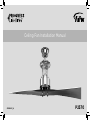
Ceiling Fan Installation Manual
P257093089925_A

Date Pu rchased
Store Purchased
Model No.
Serial No.
Vendor No.
UPC
109226
P2570
Limited Lifetime Warranty
Progress Lighting fan motors are warranted to the original purchaser to be free of electrical and/or mechanical defects for so
long as the original purchaser owns the fan. Pull chain switches, reverse switches, capacitors and metal finishes are warranted to
be free from defects in materials or workmanship for a period of 1 year from the date of purchase. Warping of wooden or plastic
blades is not covered by this warranty nor is corrosion and/or deterioration of any finishes for fans installed within ten miles of
any sea coast. Extended warranties for ENERGY STAR
®
qualified products may apply.
Progress Lighting ceiling fans with built-in LED light sources, when properly installed and under normal conditions of use, are
warranted to be free from defects in material and workmanship which cause the light sources to fail to operate in accordance
with the specifications for (i) five (5) years from the date of purchase on the LED Light modules and electrical components for
fans used in single family residences, and (ii) three (3) years from the date of purchase on the LED Light modules and electrical
components for fans used in multi-family or commercial applications. LED bulbs supplied by Progress Lighting carry no
warranty other than manufacturer’s warranty. Non-LED bulbs carry no warranty.
With proof of purchase, the original purchaser may return the defective fan to the place of purchase during the first 30 days for
replacement. After 30 days, the original purchaser MUST contact Progress Lighting at (864) 678-1000 for repair or replacement
which shall be determined in Progress Lighting’s sole discretion and shall be purchaser’s sole and exclusive remedy.
Labor and Shipping Excluded. This warranty does not cover any costs or fees associated with the labor (including, but not
limited to, electrician’s fees) required to install, remove, or replace a fan or any fan parts.
This warranty shall not apply to any loss or damage resulting from (i) normal wear and tear or alteration, misuse, abuse or
neglect, or (ii) improper installation, operation, repair or maintenance by original purchaser or a third party, including without
limitation improper voltage supply or power surge, use of improper parts or accessories, unauthorized repair (made or
attempted) or failure to provide maintenance to the fan.
THE FOREGOING WARRANTIES STATE PROGRESS LIGHTING’S ENTIRE WARRANTY OBLIGATION AND
ORIGINAL PURCHASER’S SOLE AND EXCLUSIVE REMEDY RELATED TO SUCH PRODUCTS. PROGRESS
LIGHTING IS NOT RESPONSIBLE FOR DAMAGES (INCLUDING INDIRECT, SPECIAL, INCIDENTIAL OR
CONSEQUENTIAL), DUE TO PRODUCT FAILURE, WHETHER ARISING OUT OF BREACH OF WARRANTY,
BREACH OF CONTRACT, OR OTHERWISE. THIS WARRANTY IS GIVEN IN LIEU OF ALL OTHER WARRANTIES,
WHETHER EXPRESSED OR IMPLIED, INCLUDING THOSE OF MERCHANTABILITY, FITNESS FOR A PARTICULAR
PURPOSE OR NONINFRINGEMENT.
Some states do not allow limitations on how long an implied warranty lasts or the exclusion or limitations of incidental or
consequential damages, so the above limitations and exclusions may not apply to you. This warranty gives you specific rights
and you may have other rights which vary from state to state.
785247221653
785247221660
785247221646

Table of Contents
Safety Rules.....................................................................................................................................................................................
Unpacking Your Fan .......................................................................................................................................................................
Installing Your Fan ..........................................................................................................................................................................
Operating Your Transmitter ..........................................................................................................................................................
Care of Your Fan ...........................................................................................................................................................................
Troubleshooting ............................................................................................................................................................................
Specifications ................................................................................................................................................................................
1.
2.
3.
11.
13.
14.
15.

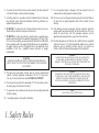
1. Safety Rules
1. To reduce the risk of electric shock, insure electricity has been turned off
at the circuit breaker or fuse box before beginning.
2. All wiring must be in accordance with the National Electrical Code and
local electrical codes. Electrical installation should be performed by a
qualified licensed electrician.
3. WARNING: To reduce the risk of electrical shock and fire, do not use
this fan with any solid-state fan speed control device.
4. WARNING: To reduce the risk of fire, electric shock, or personal injury,
mount to outlet box marked "Acceptable for Fan Support of 15.9 kg (35 lbs.)
Or Less" and use mounting screws provided with the outlet box. Most outlet
boxes commonly used for the support of light fixtures are not acceptable for
fan support and may need to be replaced. Due to the complexity of the
installation of this fan, a qualified licensed electrician is strongly
recommended.
WARNING
TO REDUCE THE RISK OF FIRE, ELECTRIC SHOCK OR PERSONAL
INJURY, MOUNT FAN TO OUTLET BOX MARKED ACCEPTABLE FOR
FAN SUPPORT.
5. The outlet box and support structure must be securely mounted and
capable of reliably supporting a minimum of 35 lbs (15.9 kg) or less.
Use only UL-listed outlet boxes marked FOR FAN SUPPORT.
6. The fan must be mounted with a minimum of 7 ft (2.1m) clearance from
the trailing edge of the blades to the floor.
7. To operate the reverse function on this fan, press the reversing button while
the fan is running.
8. Avoid placing objects in the path of the blades.
9. To avoid personal injury or damage to the fan and other items, be
cautious when working around or cleaning the fan.
10. Do not use water or detergents when cleaning the fan or fan blades. A
dry dust cloth or lightly dampened cloth will be suitable for most
cleaning.
11. After making electrical connections, spliced conductors should be
turned upward and pushed carefully up into the outlet box. The wires
should be spread apart with the grounded conductor and the
equipment-grounding conductor on one side of the outlet box.
12. Electrical diagrams are for reference only. Light kits that are not packed
with the fan must be UL Listed and marked suitable for use with the
model fan you are installing. Switches must be UL General Use
Switches. Refer to the Instructions packaged with the light kits
NOTE
READ AND SAVE ALL INSTRUCTIONS!
WARNING
TO REDUCE THE RISK OF PERSONAL INJURY, DO NOT BEND THE
BLADE ARMS (ALSO REFERRED TO AS BRACKETS) DURING
ASSEMBLY OR AFTER INSTALLATION. DO NOT INSERT OBJECTS IN
THE PATH OF THE BLADES.
WARNING
THIS PRODUCT CONTAINS CHEMICALS KNOWN TO THE STATE OF
CALIFORNIA TO CAUSE CANCER, BIRTH DEFECTS AND /OR OTHER
REPRODUCTIVE HARM. THOROUGHLY WASH HANDS AFTER
INSTALLING, HANDLING, CLEANING, OR OTHERWISE TOUCHING
THIS PRODUCT.

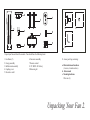
Unpack your fan and check the contents. You should have the following items:
Unpacking Your Fan 2.
10. Loose parts bag containing:
a. Blade attachment hardware
(4 screws, 4 metal washers )
b. Allen wrench
c. Mounting hardware
Wire nuts (3)
1. Fan blades (5)
2. Canopy assembly
3. Ball/downrod assembly
4. Coupling cover
5. Decorative scroll
6.
Fan motor assembly
7. Remote control
8. 12V MN21/A23 battery
9. Balancing kit
3
1
2
4
5
6
10
ac
b
7
8
9

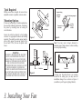
Tools Required
Phillips screw driver, straight slot screw driver,
adjustable wrench, step ladder, and wire cutters.
Mounting Options
If there isn't an existing UL listed mounting box,
then read the following instructions. Disconnect
the power by removing fuses or turning off
circuit breakers.
Secure the outlet box directly to the building
structure. Use appropriate fasteners and building
materials. The outlet box and its support must be
able to fully support the moving weight of the
fan (at least 35 lbs). Do not use plastic outlet
boxes.
Figure 4
Figure 3
Figure 1
Figure 2
Outlet box
Outlet box
Outlet box
Note: You may need a longer downrod to
maintain proper blade clearance when installing
on a steep, sloped ceiling.
To hang your fan where there is an existing
fixture but no ceiling joist, you may need an
installation hanger bar as shown in Figure 4
(available at your Progress Lighting Retailer).
3. Installing Your Fan
WARNING
TO REDUCE THE RISK OF FIRE, ELECTRIC
SHOCK, OR OTHER PERSONAL INJURY,
MOUNT FAN ONLY TO AN OUTLET BOX
MARKED ACCEPTABLE FOR FAN SUPPORT
AND USE THE MOUNTING SCREWS
PROVIDED WITH THE OUTLET BOX. OUTLET
BOXES COMMONLY USED FOR THE
SUPPORT OF LIGHTING FIXTURES MAY NOT
BE ACCEPTABLE FOR FAN SUPPORT AND
MAY NEED TO BE REPLACED. CONSULT A
QUALIFIED ELECTRICIAN IF IN DOUBT.
Angled ceiling
maximum
17 angle
Recessed
outlet box
Provide strong support
Ceiling
hanger
bracket

4.
REMEMBER to turn off the power. Follow the
steps below to hang your fan properly.
NOTE: This ceiling fan is supplied with two types
of hanging assemblies; the standard ceiling
installation using the downrod with ball and socket
mounting, and the "close-to-ceiling" mounting.
The "close-to-ceiling" mounting is recommended
in rooms with less than 8-foot ceilings or in areas
where additional space is desired from the floor to
the fan blades.
When using the standard downrod installation, the
distance from the ceiling to the bottom of the fan
blades will be approximately 18 1/8 inches. The
"close-to-ceiling" installation reduces the distance
from the ceiling to the bottom of the fan blades to
approximately 9 inches.
Once you have decided which ceiling installation
you will use, proceed with the following
instructions. Where necessary, each section of the
instructions will note the different procedures to
follow for the two types of installation.
Hanging the Fan
Option 1:
Standard Ceiling Mounting
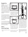
Remove the
Canopy Ring
Figure 5
Remove the canopy ring from the canopy.
(Figure 5)
1.
Remove the mounting bracket from the canopy
by loosening the four screws on the top of the
canopy. Remove the two non-slotted screws
and loosen the slotted screws. (Figure 6)
2.
Route wires exiting from the top of the fan
motor through the coupling cover, decorative
scroll, canopy cover, canopy ring, canopy and
then through the ball/ downrod. (Figure. 7)
Loosen, but do not remove the 2 set screws on
the collar on top of the motor housing.
3.
4.
Loosen but
do not Remove
Remove
Figure 6
(Figure 7)
5.
6.
Figure 7
Align the holes at the bottom of the downrod
with the holes in the coupling on top of the
motor housing. (Figure 7) Carefully insert the
clevis pin through the holes in the collar and
downrod. Be careful not to jam the clevis pin
against the wiring inside the downrod. Insert
the cotter pin through the hole near the end of
the clevis pin until it snaps into its locked
position, as noted in the circle inset of Fig. 7.
Tighten two set screws on top of the fan motor
firmly. Attach the decorative scroll to the
motor housing using the screws provided.
Pin in Locked
Positioon
Motor Collar
Coupling Cover
Screws
Decorative Scroll
Motor Wires
Ball/Downrod
Assembly
Ceiling Canopy
Canopy Cover
Canopy Ring
Cotter Pin
Tighten Screw
Firmly
Clevis Pin

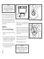
5.
Remove three of the six screws and lock
washers (every other one) from the collar of
top motor. (Figure 9)
Route the wires exiting the top of the fan motor
through the canopy ring (make sure the slot
openings are on top). then proceed to place the
ceiling canopy over the collar at the top of the
motor. (Figure 10)
Align the mounting holes with the holes in the
motor and fasten using the screws and lock
washers removed in step 4. (Fig. 10)
Tighten the mounting screws security.
4.
5.
6.
7.
Motor
Collar Screw and Lock Washer
(3 of 6 Places)
Figure 9
Option 2:
Close-to-Ceiling Mounting
Remove the canopy ring from the canopy.
(Figure 5)
Remove the mounting bracket from the canopy
by loosening the four screws on the top of the
canopy. Remove the two non-slotted screws
and loosen the slotted screws. (Figure 6)
Remove the decorative canopy bottom cover
from the canopy by turning the canopy bottom
cover counterclockwise. (Figure 8)
1.
2.
3.
Canopy
Bottom
Cover
Remove
Figure 8
Figure 10
Collar
Ceiling
Canopy
Screw and
Lock Washer
(3 Places)
Canopy Ring
NOTE: If a longer downrod is needed, take out
the screw located in the hanger ball, lower the
hanger ball and remove the pin, remove all 3
pieces from the downrod and assemble them onto
the new longer downrod before proceeding step 3.
(The longer downrod is available at any Progress
Lighting retailer)
WARNING
FAILURE TO PROPERLY INSTALL
CLEVIS PIN AS NOTED IN STEP 5
COULD RESULT IN FAN LOOSENING
AND POSSIBLY FALLING.
WARNING
FAILURE TO COMPLETELY TIGHTEN
THE THREE SCREWS IN STEP 7 COULD
RESULT IN FAN LOOSENING AND
POSSIBLY FALLING.

6.
WARNING
WHEN USING THE STANDARD BALL/
DOWNROD MOUNTING. THE TAB IN THE
RING MUST REST IN THE GROOVE OF THE
HANGER BALL. FAILURE TO PROPERLY SEAT
THE TAB IN THE GROOVE COULD CAUSE
DAMAGE TO WIRING.
WARNING
THE TAB AS SHOWN IN FIGURE 12 IS ONLY
TO BALANCE THE FAN WHILE ATTACHING
WIRING. FAILURE TO HANG AS SHOWN IN
FIGURE 12 MAY RESULT IN TAB BREAKING
CAUSING THE FAN TO FALL. TAB MUST PASS
FROM INSIDE TO OUTSIDE OF CANOPY.
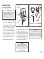
Installing Fan to
the Electrical Box
Figure 11
Carefully lift the fan assembly up to the ceiling
mounting bracket and hang the fan on the tab
provided by utilizing one of the holes at the outer
rim of the ceiling canopy. (Figure 12) If use
standard mounting, seat the hanger ball in the
mounting bracket socket. Make sure the tab on
the mounting bracket socket is properly seated in
the groove in the hanger ball. (Figure 12)
4.
Pass the 120-volt supply wires through the
center hole in the mounting bracket. (Figure 11)
Attach the mounting bracket on the outlet box
by sliding the mounting bracket over the screws
provided with the outlet box. (Figure 11) When
using “close-to-ceiling” mounting, it is
important that the mounting bracket be level. If
necessary, use leveling washers (not included)
between the mounting bracket and the outlet
box. Note that the flat side of the mounting
bracket is toward the outlet box. (Figure 11)
Securely tighten the two mounting screws.
1.
2.
3.
Figure 12
Groove
Standard Mounting
Close-to-Ceiling Mounting
Tab
CUL Listed
Outlet Box
Ceiling Mounting
Bracket
Mounting
Screws (Supplied
with Outlet Box)
120V
Wires
WARNING
TO REDUCE THE RISK OF FIRE, ELECTRIC
SHOCK OR OTHER PERSONAL INJURY. MOUNT
FAN ONLY TO AN OUTLET BOX OR
SUPPORTING SYSTEM MARKED ACCEPTABLE
FOR FAN SUPPORT AND USE THE MOUNTING
SCREWS PROVIDED WITH THE OUTLET BOX.

7.
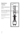
Make the Electric
Connections
WARNING: To avoid possible electrical shock,
be sure electricity is turned off at the main fuse box
before wiring.
Step 1. Motor to House Supply Wires Electrical
Connections: Connect the WHITE wire (Neutral)
from the outlet box to the WHITE wire marked
"AC in N" from the motor. (Fig. 13)
Step 2. Connect the BLACK wire (Hot) from the
outlet box to the BLACK wire marked "AC in L"
from the motor. (Fig. 13)
Secure all wire connections with the plastic wire
nuts provided.
Figure 13
Outlet Box
Black ("AC IN L")
White ("AC IN N")
White (Neutral)
Black (Hot)
Green or bare
copper (ground)
Ground (green)
(Connect to ground
wire on hanger
bracket if no house
ground wire exists.)

8.
WARNING
MAKE SURE THE TAB ON THE HANGING
BRACKET PROPERLY SITS IN THE GROOVE IN
THE HANGER BALL BEFORE ATTACHING THE
CANOPY TO THE BRACKET BY TURNING THE
HOUSING UNTIL IT DROPS INTO PLACE.
WARNING
LOCKING SLOTS OF CEILING CANOPY ARE
PROVIDED ONLY AS AN AID TO MOUNTING.
DO NOT LEAVE FAN ASSEMBLY
UNATTENDED UNTIL ALL FOUR CANOPY
SCREWS ARE ENGAGED AND FIRMLY
TIGHTENED.
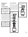
Figure 14
Canopy
Outlet Box
Hanger
Bracket
Groove
Tab
Screws
Canopy
Ring
Canopy
Outlet Box
Hanger
Bracket
Screws
Canopy
Ring
Figure 15
Finishing the Fan
Installation
Standard Ceiling Mounting
Slide canopy up to the ceiling as shown in Figure
14. Make sure you place the wires safely into the
outlet box. Secure the canopy to the hanger
bracket with the four screws with your fan. Raise
up canopy ring and line up the 4 tabs with the 4
grooves on the canopy. Once lined up, slide the
canopy ring and secure it to the canopy until snug.
Remove the fan from the tab on the hanger
bracket. Secure the canopy to the hanger bracket
with four screws included with your fan. (Fig. 15)
Raise up canopy ring and line up the 4 tabs with
the 4 grooves on the canopy. Once lined up, slide
the canopy ring and secure it to the canopy until
snug.
Close-to-Ceiling Mounting

9.
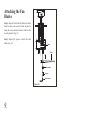
Attaching the Fan
Blades
Step 1. Align the holes from the blade to the holes
from the motor, and secure the blade in place by
using the screws and metal washers with the allen
wrench provided. (Fig. 16)
Step 2. Repeat this process to attach the other
blades. (Fig. 16)
Figure 16
Motor
Blade
Screws
Allen wrench
Metal washer

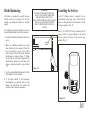
Blade Balancing
All blades are grouped by weight. Because
natural woods very in density, the fan may
wobble even though the blades are weighed
equally.
The following procedure should correct most
fan wobbling problems. Check after each step.
1. Check that all blade and blade arm screws are
secure.
2. Most fan wobbling problems are caused
when blade levels are unequal. Check this
level by selecting a point on the ceiling
above the tip of one of the blades. Measure
this distance as shown in Figure 17. Rotate
the fan until the next blade is positioned for
measurement. Repeat for each blade. The
distance deviation should be equal within
1/8".
3. Use the enclosed Blade Balancing Kit if the
blade wobble is still noticeable.
4. If the blade wobble is still noticeable,
interchanging two adjacent (side by side)
blades can redistribute the weight and
possibly result in smoother operation.
Touching
ceiling
Figure 17
WARNING
TO REDUCE THE RISK OF PERSONAL
INJURY, DO NOT BEND THE BLADE
HOLDERS WHILE INSTALLING,
BALANCING THE BLADES, OR CLEANING
THE FAN. DO NOT INSERT FOREIGN
OBJECTS BETWEEN ROTATING FAN
BLADES.
10.
Installing the battery
Your DC brushless motor is equipped with an
automatically learned type remote control. Restore
power to ceiling fan and test the transmitter as below
for proper operation. (Fig. 18)
Install a 12V MN21/A23 battery (included) into the
remote control. To prevent damage to the remote
control, remove the battery if not used for long
periods. (Fig. 18)
Figure 18
ON ECE
1234
ON
D
ON ECE
ON
D

11. Operating Your Transmitter
NOTE: If the self calibration test failed, turn the AC
power off; restore power and process the self
calibration test again.
NOTE: During self calibration test, the remote is
non-fuctional.
NOTE: The learning frequency function and self
calibration test will continue to retain the last set
frequency and calibration set even when the AC
power is shut off. If the frequency is changed the self
calibration test will occur again.
“D” and “ON” dip switch:
1. The “ON” selection is the light dimmable selection
and is to be used with all bulbs except for CFL bulbs.
The “D” selection is the light ON only (no dimming
function) and is to be used with CFL bulbs as CFL
bulbs in most cases cannot be used with dimming
controllers.
This receiver provides the following protective
function:
1. Lock Rotor Position: The DC motor has a built-in
safety against a stalled or locked rotor condition
(stalled blade rotation). If there is an obstruction or
fault with the motor, the current monitoring function
will automatically turn power off to the motor after 30
seconds. Remove the obstruction and turn the AC
power off. Restore power and re-start fan motor.
2. Over 80W protection: When the receiver detects
motor power consumption which is greater than 80W,
the receiver power will be stopped and operation will
immediately discontinue. Wait for 5 seconds and then
turn the receiver power back on.
Remote Control Button Definitions:
These six buttons are used to set the fan speed as
follows:
I = minimum speed
II = low speed
III = medium low speed
IV = medium speed
V = medium high speed
VI = high speed
button: Turns the fan off.
button: Controls fan direction.
Setting the Remote Control
Follow the below steps to set the remote control:
The auto learning function will only mandate within 60
seconds when turning the fan’s AC power ON.
1. Select desired frequency from the back of transmitter.
2. From the back of the transmitter, press the “SET”
button, and hold the “SET” button for over 5 seconds.
Once the receiver has detected the frequency, the light
will flash twice, and the fan will automatically begin to
operate and start to rotate in the counterclockwise
direction and on the highest RPM for 3 minutes. When
counterclockwise rotation has finished, the fan will
automatically reverse to clockwise direction again to the
highest RPM for 3 minutes. Fan will shut off when the
self calibration test has finished. The total self
calibration test will last about 6 minutes.
Figure 19

Speed settings for warm or cool weather depend on
factors such as the room size. Ceiling height, number
of fans and so on.
NOTE: To operate the reverse function on this fan,
press the reverse button while the fan is running.
Warm weather - (Forward) A downward airflow
creates a cooling effect as shown in Fig. 20. This
allows you to set your air conditioner on a warmer
setting without affecting your comfort.
Cool weather - (Reverse) An upward airflow moves
warm air off the ceiling area as shown in Fig. 21. This
allows you to set your heating unit on a cooler setting
without affecting your comfort.
Figure 20
Figure 21
12.

Here are some suggestions to help you maintain your
fan
1. Because of the fan's natural movement, some
connections may become loose.
Check the support
connections, brackets, and blade attachments
twice a year.
Make sure they are secure.
(It is not
necessary to remove fan from ceiling.)
2. Clean your fan periodically to help maintain its new
appearance over the years. Use only a soft brush or
lint-free cloth to avoid scratching the finish. The
plating is sealed with a lacquer to minimize
discoloration or tarnishing. Do not use water when
cleaning. This could damage the motor, or the wood,
or possibly cause an electrical shock.
3. You can apply a light coat of furniture polish to the
wood blades for additional protection and enhanced
beauty. Cover small scratches with a light application
of shoe polish.
4.
There is no need to oil your fan.
The motor has
permanently lubricated bearings.
IMPORTANT
MAKE SURE THE POWER IS OFF AT THE
ELECTRICAL PANEL BOX BEFORE YOU
ATTEMPT ANY REPAIRS. REFER TO THE
SECTION "MAKING ELECTRICAL
CONNECTIONS"
13.
Care of Your Fan

Troubleshooting
14.
Solution
1. Check circuit fuses or breakers.
2. Check line wire connections to the fan and switch wire connections in the switch housing.
CAUTION: Make sure main power is off.
3. Check to make sure the dip switches from the transmitter and receiver are set to the same frequency.
1. Make sure all motor housing screws are snug.
2. Make sure the screws that attach the fan blade bracket to the motor hub is tight.
3. Make sure wire nut connections are not rubbing against each other or the interior wall of the switch housing.
CAUTION: Make sure main power is off.
4. Allow a 24-hour "breaking-in" period. Most noise associated with a new fan disappear during this time.
5. If using an optional light kit, make sure the screws securing the glassware are tight. Check that light bulb is also secure.
6. Some fan motors are sensitive to signals from solid-state variable speed controls. If you have installed this type of control,
choose and install another type of control.
7. Make sure the upper canopy is a short distance from the ceiling. It should not touch the ceiling.
1. Do not connect the fan with wall mounted variable speed control (s).
2. Make sure the dip switches are set correctly.
Problem
Fan will not start.
Fan sounds noisy.
Remote control
malfunction

15.
Specifications
2017 Progress Lighting, Inc.
701 Millennium Blvd.,
Greenville, SC 29607
All Rights Reserved
c
17.41
lbs
19.84
lbs
2.10'
Fan Size Speed
Volts
Amps
Watts
RPM
CFM
N.W. G.W. C.F.
56"
Low
High
120
120
These are approximate measures. They do not include Amps and Wattage used by the light kit.
0.046
0.43
2.08
32.67
53
159
1951.56
6767.71

Manual de Instalación del Ventilador de Techo
P257093089925_A

Fecha de compra
Lugar de compra
N de modelo.
N de serie
Numero de vendedor
UPC
Garantía limitada de por vida
Se garantiza al comprador original que los motores de los ventiladores de Progress Lighting no presentan defectos mecánicos o
eléctricos por el tiempo durante el cual el comprador original sea dueño del ventilador. Los interruptores de cadena, interruptores
de reversa, capacitores y acabados de metal cuentan con garantía libre de defectos de materiales o mano de obra por 1 año a partir
de la fecha de compra. La deformación de las aspas de plástico o madera no está cubierta por esta garantía, así como tampoco la
corrosión y/o el deterioro de los acabados en el caso de los ventiladores instalados dentro de un radio de 10 millas (16 km) de la
costa del mar. Pueden corresponder garantías extendidas para los productos que cumplen con los requisitos de ENERGY STAR®.
Los ventiladores de techo Progress Lighting con fuentes de iluminación LED incorporadas, cuando se los instala debidamente y
bajo condiciones de uso normales, están garantizados como libres de defectos de materiales y mano de obra que hacen que las
fuentes de iluminación dejen de funcionar de acuerdo con las especificaciones durante (i) cinco (5) años a partir de la fecha de
compra para los módulos de luces LED y los componentes eléctricos para los ventiladores utilizados en residencias unifamiliares,
y (ii) tres (3) años a partir de la fecha de compra para los módulos de luces LED y los componentes eléctricos para los
ventiladores utilizados en aplicaciones comerciales o multifamiliares. Los focos LED suministrados por Progress Lighting no
cuentan con garantía más allá de la garantía del fabricante. Los focos que no son LED no cuentan con garantía.
Con comprobante de compra, el comprador original podrá devolver el ventilador defectuoso al lugar de compra, durante los
primeros 30 días, para su reemplazo. Pasados los 30 días, el comprador original DEBE contactarse con Progress Lighting al (864)
678-1000 para la reparación o el reemplazo, que se determinará a criterio exclusivo de Progress Lighting y será la compensación
única y exclusiva del comprador.
Se excluye la mano de obra y el envío. Esta garantía no cubre los costos o cargos asociados con la mano de obra (incluidos, entre
otros, los honorarios del electricista) necesaria para instalar, quitar o reemplazar el ventilador o cualquiera de sus partes.
Esta garantía no se aplicará a ninguna pérdida o daño que resulte del (i) uso y desgaste normales o de una alteración, uso indebido
o descuido, o de la (ii) instalación, operación, reparación o mantenimiento inadecuados por parte del comprador original o de un
tercero, incluidos, entre otros, suministro de voltaje inadecuado o sobrecarga eléctrica, uso de piezas o accesorios inadecuados,
reparación no autorizada (realizada o que se intentó realizar) o falta de mantenimiento al ventilador.
LAS GARANTÍAS PRECEDENTES ESTABLECEN LA OBLIGACIÓN DE GARANTÍA COMPLETA DE PROGRESS LIGHTING Y LA
COMPENSACIÓN ÚNICA Y EXCLUSIVA DEL COMPRADOR ORIGINAL EN RELACIÓN CON DICHOS PRODUCTOS. PROGRESS
LIGHTING NO ASUME RESPONSABILIDAD POR DAÑOS (INCLUIDOS INDIRECTOS, ESPECIALES, INCIDENTALES O
EMERGENTES), DEBIDO A FALLAS DEL PRODUCTO, YA SEA QUE SURJAN DEL INCUMPLIMIENTO DE LA GARANTÍA, DEL
INCUMPLIMIENTO CONTRACTUAL O DE OTRO MODO. ESTA GARANTÍA REEMPLAZA CUALQUIER OTRA GARANTÍA, YA SEA
EXPRESA O IMPLÍCITA, INCLUSO AQUELLAS DE COMERCIABILIDAD, IDONEIDAD PARA UN FIN EN PARTICULAR O NO
INCUMPLIMIENTO.
Algunos estados no permiten limitaciones sobre la duración de una garantía implícita o la exclusión de limitaciones de daños
incidentales o emergentes, de modo que las limitaciones y exclusiones anteriores tal vez no se apliquen a su caso. La presente
garantía le otorga derechos específicos y es posible que usted tenga otros derechos que varían según el estado.
P2570
785247221653
785247221660
785247221646
109226

Tabla de Contenido
Normas de seguridad .......................................................................................................................................................................
Cómo desembalar el ventilador ......................................................................................................................................................
Cómo instalar el ventilador .............................................................................................................................................................
Operando su transmisor ................................................................................................................................................................
Cómo cuidar del ventilador ...........................................................................................................................................................
Resolución de problemas ..............................................................................................................................................................
Especificaciones ............................................................................................................................................................................
1.
2.
3.
11.
13.
14.
15.

1. Normas de seguridad
1. Para reducir el riesgo de eléctrocución, asegurarse de que la eléctricidad se
ha desactivado en el cortacircuitos o caja de fusibles antes de comenzar.
2. Todo cableado debe relizarse conforme al Código Electrico Nacional y los
códigos electricos locales. La instalación eléctrica debe ser relazada por un
eléctricista registrado calificado.
3. ADVERTENCIA: Para reducir el riesgo de una electrocuion e incendio,
no usar este ventilador con ningun dispositivo de esto s lido para control
de la velocidad del ventilador.
4. ADVERTENCIA: para reducir el riesgo de incendio, descarga eléctrica o
lesión personal, monte a una caja distribución marcada como "Aceptable para
soporte de un ventilador de 15.9kg (35 lbs.) de peso o menos" y monte con
los tornillos proporcionados con la caja de distribución. La mayoría de las
cajas de conexión utilizadas para soportar artefactos de iluminación, no son
aptas para colgar un ventilador y podría ser necesario cambiarlas. Debido a la
complejidad de la instalación de este ventilador, se recomienda
encarecidamente que la realice un electricista licenciado cualificado.
ADVERTENCIA
PARA REDUCIR EL RIESGO DE INCENDIO ELECTROCUCIÓN O
LESIONES PERSONALES. MONTAR EL VENTILADOR EN UNA CAJA DE
DISTRIBUCIÓN MARCADA CÓMO ACEPTABLE PARA SOPORTE DE
VENTILADORES.
5. La caja de distribución y la estructura de soporte deben estar montados
de manera segura y deben ser capaces de soportar, de manera confiable,
unminimo de 35 libras (15,9 kilogramos). Usar solamente cajas de
distribución listadas por UL. marcadas "PARA SOPORTEDE
VENTILADORES".
6. EL ventilador debe estar montado con un m nimo de 7 pies (2.1m) de
espacio libre desde el borde posterior de las aspas hasta el piso.
7.
Invierta el ventilador con el motor encendido a cualquier velocidad.
8. Evitar colocar objetos qen interfiera el giro de las aspas.
9. Para evitar lesiones personales o da os al ventilador y otros articulos,
tener cuidado al trabajar cerca del ventilador o al limpiarlo.
10. No usar agua o detergentes al limpiar el ventilador o las aspas del
ventilador. Para la mayoria de los propsitos de limpieza, un paño seco o
ligeramente humedecido será apropiado.
11. Despues de realizar las conexiones eléctricas, los conductores
empalmados se deben voltear hacia arriba y se deben empujar con
cuidado hacia dentro de la caja de distribución. Los cables deben estar
separados, con el conductor a tierra y el conductor a tierra del equipo en
un lado de la caja de distribución.
12. Los diagramas eléctricos son para referencia únicamente. Los juegos de
iluminación que no estén embalados con el ventilador deben estar
Listados por U.L. y marcados como apropiados para ser usados con el
modelo de ventilador que se está instalando. Los interruptores deberán
ser Interruptores para uso general U.L. Réfierase a las instrucciónes
embaladas con los juegos de iluminación e interruptores para obtener
información sobre el montaje adecuado.
NOTA
!LEER Y GUARDAR TODAS LAS INSTRUCCIONES!
ADVERTENCIA
PARA REDUCIR EL RIESGO DE LESIONES PERSONALES, NO DOBLAR LOS
SOPORTES DE LAS ASPAS (TAMBIEN LLAMADOS"REBORDES" DURANTE EL
MONTAJE O DESPUES DE LA INSTALACIÓN NO INSERTAR OBJETOS EN LA
TRAYECTORIA DE LAS ASPAS.
ADVERTENCIA
ESTE PRODUCTO CONTIENE SUBSTANCIAS QUÍMICAS QUE SEGÚN EL
ESTADO DE CALIFORNIA CAUSA CÁNCER, DEFECTOS DE NACIMIENTO Y (O)
DAÑO AL SISTEMA REPRODUCTOR. LAVARSE BIEN LAS MANOS DESPUÉS DE
INSTALAR, MANIPULAR, LIMPIAR O TOCAR DE MANERA ALGUNA ESTE
PRODUCTO.

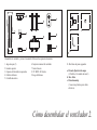
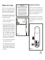
Desembalar el ventilador y revisar el contenido. Debe tener los siguientes elementos:
1. Juego de aspas (2)
2. Escudete superior
3. Conjunto de bola/tubo de suspensión
4. Cubridor del motor
5. Cortinilla decorativa
6. Conjunto de motor del ventilador
7. Control remoto
8. 12V MN21/A23 bateria
9. Juego de balanceo
10
Cómo desembalar el ventilador 2.
10. Dos bolsas de piezas pequeñas:
a. Piezas de fijación de las aspas
(4 Tornillos, 4 Arandelas de metal )
b. Ilave Allen
c. Piezas demontaje
(3 conectores plásticos para cables
eléctricos).
3
1
2
4
5
6
7
8
9
ac
b

Herramienta necesarias
Destornillador Phillips, destornillador normal,
llave de tuercas ajustable, escalera de tijera, y
cortadoras de alambre.
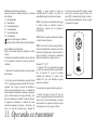
Opciones de instalación
Si no hay una caja con UL registración de
montaje existente, sirvase leer las siguientes
instrucciones. Desconectar el suministro de
electricidad removiendo los fusibles o
desactivando los cortacircuitos.
Asegurar la caja de distribución directamente a
la estructura del edificio. Usar los sujetadores y
meteriales de construcción apropiados. La caja
de distribución y su soporte deben ser capaces de
soportar completamente el peso en movimiento
del ventilador (al menos 35 libras o 15.9 kgs.)
No usar cajas de distribución plásticas.
Figura 4
Figura 3
Figura 1
Figura 2
Caja de
distribución
Caja de
distribución
Caja de distribución
Nota: Ud. Puede necesitar una barra de extension
para mantener la distancia apropiada de las aspas
cuando la instalación se efectúe en un techo
inclinado.
Para colgar su ventilador donde ya existe una
instalación pero no una viga de techo, es possible
que se necesite una instalación de barra de
suspención como se muestra la Figura 4
(disponible en su distribuidor Progress Lighting).
3. Cómo instalar el ventilador
ADVERTENCIA
PARA REDUCIR EL RIESGO DE INCENDIO,
ELECTROCUCIÓN O DAÑO PERSONAL,
INSTALAR EL VENTILADOR A UNA CAJA DE
DISTRIBUCION MARCADA "ACEPTADA
PARA SOPORTAR VENTILADOR" Y USAR
LOS TORNILLOS DE MONTAJE
SUMINISTRADOS CON LA CAJA DE
DISTRIBUCION
Angulo máximo en
el techo: 17°
Caja de
distribución
embutida
Brindar soporte fuerte
Soporte de
montaje

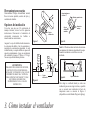
RECUERDE apagar la corriente. Siga estos pasos
para colgar su ventilador correctamente.
NOTA: Este ventilador de techo incluye dos tipos
de montajes colgantes; la instalación de techo
estándar con la varilla con montaje con bola y
zócalo, y el montaje "junto al techo". El montaje
"junto al techo" se recomienda en habitaciones con
el techo más bajo de 2,44m o en lugares donde
desee más espacio entre el suelo y las palas del
ventilador.
Cuando utilice la instalación estándar con varilla,
la distancia del techo a la parte inferior de las palas
del ventilador será de unos 46,04 cm. La
instalación "junto al techo" reduce la distancia
entre el techo y la parte inferior de las palas del
ventilador a aproximadamente 22,86 cm.
Una vez decidida la instalación a utilizar, siga
estas instrucciones. Cuando sea necesario, cada
sección de las instrucciones indicará los diferentes
pasos a seguir para los dos tipos de instalación.
Colgar el Ventilador
Opción 1:
Monataje Estándar de Techo
Retire el anillo de la cubierta. (Figura 5)
1.
Retire el soporte de montaje de la cubierta
aflojando los cuatro tornillos de la parte
superior de la cubierta. Retire los dos tornillos
sin ranuras y afloje los tornillos con ranuras .
(Figura 6)
2.
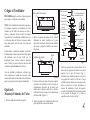
Guíe los cables que salen de la parte superior
del motor del ventilador a través del tapa de
acoplamiento, decorativo de la voluta, tapa
inferior de la cubierta, anillo de la cubierta,
cubierta del techo y luego a través del montaje
de bola/varilla.
(Figura. 7)
Afloje sin quitar los 2 tornillos del collar de la
parte superior de la carcasa del motor.
3.
4.
Alinee los agujeros de la parte inferior de la
barra con los agujeros del cuello en la parte
superior de la caja del motor. (Fig. 7)
Introduzca con cuidado el chaveta a través de
los agujeros del cuello y de la barra. Tenga
cuidado de que el chaveta no se atasque con los
hilos de dentro de la barra. Introduzca el
chaveta de seguridad a través del agujero
cercano al extremo del chaveta hasta que quede
en la posición de bloqueo, tal y cómo se
especifica en el circulo de la Fig. 7.
5.
Retire el anillo de la cubierta
Figura 5
Aflójelos sin quitarlos
Quitar
Cables del motor
Montaje con
bola/varilla
Cubierta del techo
Anillo de la
cubierta
Tapa inferior de
la cubierta
Apretar los
tornillors
con fimeza
Collar del
motor
Posición de bloqueo de
entrada del conector
Chaveta Chaveta de
seguridad
Tapa de acoplamiento
Figura 6
Figura 7
Tornillos
Decorativo de
la voluta
4.

Figura 10
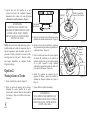
Retire la tapa inferior de la cubierta decorativa
girándola en sentido contrahorario3. (Figura 8)
Remover tres de los seis tornillos y arandelas
de seguridad (uno por medio) asegurando de la
cubierta del motor. (Figura 9)
Guíe los cables que salen de la parte superior
del motor del ventilador por el anillo de la
cubierta (asegúrese de que las ranuras queden
en la parte superior). Luego continúe
colocando la tapa del techo sobre el collar en la
parte superior del motor. (Figura 10)
Alinee los agujeros de montaje con los
agujeros del motor y apriete los tornillos y
arandelas de bloqueo quitados en el paso 4.
(Fig. 10)
Apriete bien los tornillos de montaje.
3.
4.
5.
6.
7.
Collar
Collar del
motor
Tornillo y arandela de
bloqueo (3 de 6 lugares)
Figura 9
Cubierta
del techo
Tornillo y
arandela de
bloqueo
(3 lugares)
Anillo de la
cubierta
Opción 2:
Montaje Junto al Techo
Retire el anillo de la cubierta. (Figura 5)
Retire el soporte de montaje de la cubierta
aflojando los cuatro tornillos de la parte
superior de la cubierta. Retire los dos tornillos
sin ranuras y afloje los tornillos con ranuras.
(Figura 6)
1.
2.
Tapa inferior
de la cubierta
Quitar
NOTA: Si necesita una varilla más larga, quite el
tornillo situado en la bola de suspensión, baje la
bola de suspensión y quite el pasador, quite las 3
piezas de la varilla y móntelas en la nueva varilla
más larga antes de ir al paso 3. (Existen varillas
más largar disponibles en cualquier tienda
Progress Lighting)
ADVERTENCIA
SI NO INSTALA EL CHAVETA DE
SEGURIDA DCORRECTAMENTE COMO
SE INDICA EN EL PASO 5, PODRÍA
PROVOCAR QUE EL VENTILADOR SE
SUELTE Y SE CAIGA.
Figura 8
ADVERTENCIA
SI NO APRIETA POR COMPLETO LOS
TRES TORNILLOS DEL PASO 7 PODRÍA
PROVOCAR QUE EL VENTILADOR SE
SUELTE Y SE CAIGA.
Apriete bien los dos tornillos de la parte
superior del motor del ventilador. Conecte el
decorativo de la voluta a la caja del motor
utilizando las tornillas incluidas. (Figura 7)
6.
5.

6.
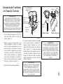
Figura 11
Instalación del Ventilador
a la Toma de Corriente
Pasa los cables de suministro de 120 Volts a
través del orificio central en el soporte de
montaje. (Figura 12)
Monta el soporte de montaje sobre la caja
eléctrica deslizando el soporte de montaje
sobre los tornillos suministrados con la caja
eléctrica. (Figura 11) Cuando uses el montaje
“cerca del techo” es importante que el soporte
de montaje esté nivelado. Si fuera necesario,
utiliza arandelas niveladoras (no incluidas)
entre el soporte de montaje y la caja eléctrica.
Fíjate que el lado plano del soporte de montaje
esté hacia la caja eléctrica. (Figura 11)
Apriete bien los dos tornillos de montaje.
1.
2.
3.
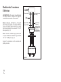
Levante con cuidado el montaje del ventilador
hacia el soporte del techo y cuélguelo en la
lengüeta incluida utilizando uno de los
agujeros del anillo exterior de la cubierta del
techo. (Figura 12) Si utiliza un montaje
estándar, asiente la bola colgante en el zócalo
del soporte de montaje. Asegúrese de que la
lengüeta del zócalo del soporte de montaje
quede bien asentada en la ranura de la bola
colgante. (Figura 12)
4.
Figura 12
Montaje junto al techo
Lengüeta
Ranura de
registro
Montaje estándar
Soprte de
montaje en
el techo
Cables
CA
Tornillos de
montaje
(incluidos con la
toma de corriente)
Caja de distribución
aprobada por CUL
ADVERTENCIA
PARA REDUCIR EL RIESGO DE FUEGO,
DESCARGA ELÉCTRICA U OTRAS LESIONES
PERSONALES. MONTE EL VENTILADOR
SOLAMENTE A UNA TOMA DE CORRIENTE O
SISTEMA DE SOPORTE MARCADO COMO
COMPATIBLE PARA SOPORTAR UN
VENTILADOR Y UTILICE LOS TORNILLOS DE
MONTAJE SUMINISTRADOS CON LA TOMA.
ADVERTENCIA
CUANDO UTILICE EL MONTAJE ESTÁNDAR
CON BOLA/VARILLA. LA LENGÜETA DEL
ANILLO DEBERÁ DESCANSAR EN LA
RANURA DE LA BOLA COLGANTE. SI NO
ASIENTA LA LENGÜETA CORRECTAMENTE
EN LA RANURA, PODRÁ PROVOCAR DAÑOS
EN EL CABLEADO.
ADVERTENCIA
LA LENGÜETA MOSTRADA EN LA FIGURA
12 SÓLO SIRVE PARA EQUI IBRAR EL
VENTILADOR AL COLOCAR EL CABLEA O.
SI NO SIGUE EL PROCEDIMIEN O DE LA
FIGURA 12, PODRÍA PROVOCAR LA R TURA
DE LA LENGÜETA Y EL VENTIL DOR
PODRÍA CAER. EL GANCHO DEBE PASAR
DEL INTERIOR AL EXTERIOR DE LA
CUBIETA.

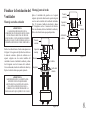
7.
Realizar las Conexiones
Eléctricas
ADVERTENCIA: Para envitar la posibilidad de
un choque eléctrico, asegurese de apagar la
corriente eléctrica desde el circuito central.
Paso 1. Haga las conexiones de la caja de
distribucion a el Receptor de la manera siguiente;
Conecte el Alambre blanco (neutral) de la caja de
distribucion al alambre blanco marcado "AC in N"
del receptor. (Fig. 13)
Paso 2. Conecte el Alambre Negro (corriente) de
la caja de distribucion al alambre Negro marcado
"AC in L" del Receptor. (Fig. 13)
Asegure las conexiones con los conectores de
plastico proveidos.
Caja de
distribucion
Negro ("AC IN L")
Blanco ("AC IN N")
Blanco (neutral)
Negro
(con corriente)
Verde o de cobre
(a tierra)
Verde (a tierra)
(Conecte al
alambre a tierra a
la abrazadera de
soporte si no
existe alambre a
terra de la casa)
Figura 13

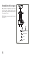
8.
ADVERTENCIA
LAS RANURAS DE BLOQUEO DE LA
CUBIERTA DEL TECHO SÓLO SIRVEN COMO
AYUDA PARA EL MONTAJE. NO DEJE EL
MONTAJE DEL VENTILADOR DESATENDIDO
HASTA QUE LOS CUATRO TORNILLOS DE LA
CUBIERTA ESTÉN FIJOS Y BIEN APRETADOS.
ADVERTENCIA
ASEGÚRESE DE QUE LA LENGÜETA DEL
SOPORTE COLGANTE QUEDE BIEN
ASENTADA EN LA RANURA DE LA BOLA
COLGANTE ANTES DE COLOCAR LA
CUBIERTA EN EL SOPORTE GIRANDO LA
CARCASA HASTA QUE QUEDE EN SU LUGAR.
Finalizar la Instalación del
Ventilador
Montaje en techo estándar
Deslice la cubierta hacia el techo como aparece en
la Figura 14. Asegúrese de fijar bien los cables en
la toma de corriente. Apriete la cubierta en el
soporte colgante con los cuatro tornillos del
ventilador. Levante el anillo de la cubierta y alinee
las 4 lengüetas con las 4 ranuras de la cubierta.
Una vez alineadas, deslice el anillo de la cubierta y
fíjelo a la cubierta hasta que quede ajustado.
Quite el ventilador del gancho en el soporte
colgante. Apriete la cubierta en el soporte colgante
con los cuatro tornillos del ventilador incluidos.
(Fig. 15) Levante el anillo de la cubierta y alinee
las 4 lengüetas con las 4 ranuras de la cubierta.
Una vez alineadas, deslice el anillo de la cubierta y
fíjelo a la cubierta hasta que quede ajustado.
Montaje junto al techo
Toma de
corriente
Soporte de
montaje
Cubierta
Anillo de la
cubierta
Tornillos
Toma de
corriente
Soporte de
montaje
Lengüetas
Ranuras
Cubierta
Anillo de la
cubierta
Tornillos
Figura 14
Figura 15

9.
Instalacion de las Aspas
Paso 1. Alinee los agujeros de la aspa en los
orificios del motor, y asegurar la aspa en su lugar
con las tornillos y arandelas de metal
con la Ilave
Allen incluida. (Fig. 16)
Paso 2. Repita este proceso para unir las otras dos
aspas. (Fig. 16)
Palas
Tornillos
Figura 16
Motor
Ilave Allen
Arandelas de metal

10.
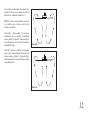
Balanceo de las Aspas
Todas las aspas están agrupadas por peso.
Debido a que la desidad de las maderas
naturales varía, el ventilador podría oscilar aún
cuando el peso de las aspas esté equilibrado.
El siguiente proceimiento deberia mayor parte
de la oscilación del ventilador. Corregir la
Verificar después de cada paso.
1. Verificar que todos los tornillos de aspas y de
soportes de aspas estén seguros.
2. La mayoría de los problemas de oscilación se
originan cuando los niveles de las aspas son
desiguales. Revisar esté nivel por medio de
seleccionar un punto del techo por encima de
la punta de una de las aspas. Medir esta
distancia como se muestra en la Figura 17.
Rotar el ventilador hasta que la siguiente
aspa esté ubicada para medición.
procedimiento para cada aspa. Las medi
repetir el das hacer fucional deben
mantenerse dentro de 1/8 pulgadas (3mm).
3. Usar el juego de balanceo de aspas incluido
si aún se puede notar la oscilación.
4. Si la oscilación de las aspas todavía se puede
notar, el intercambio de dos aspas adyacentes
(lado a lado) puede redistribuir el peso y es
posible que resulte en un funcionamiento
más uniforme.
En contacto
con el techo
Figura 17
ADVERTENCIA
PARA REDUIR RIESGO DE LESIONES
PERSONALES. NO DOBLAR LOS SUJET
ADORES DE ASPAS MIENTRAS SE
REALIZA LA INSTALACIÓN. EL
BALANCEO DE LAS ASPAS O SU
LIMPIEZA. NO INSERTAR OBJETOS
EXTRANOS ENTRE LAS ASPAS DEL
VENTILADOR EN ROTACIÓN.
Instalación de la Bateria
Su motor DC sin escobillas está equipado con un
mando a distancia con funciones automáticas
aprendidas. Vuelva a encender el ventilador de techo
y pruebe el buen funcionamiento del transmisor
como se indica a continuación. (Fig. 18)
Instala una batería MN21/A23 de 12V (incluida) en
el control remoto. Para prevenir daños al control
remoto, sacala batería si no va a usarse por largo
tiempo. (Fig. 18)
Figura 18
ON ECE
1234
ON
D
ON ECE
ON
D

11. Operando su transmisor
NOTA: Si la prueba de autocalibración falló, apagar
la corriente electrica al ventilador; restaurar la
alimentación y procesar otra vez la prueba de
autocalibración.
NOTA: Durante la prueba de calibración automática,
el control remoto no funcionará.
NOTA: La función de la frecuencia de aprendizaje y
pruebra de autocalibración se continúara a estar and la
memoria del ventilador incluso cuando la corriente se
apage al ventilador. Si la frecuencia es cambiada la
prueba de autocalibración se producirá otra vez.
Nterruptor “D” y “ON”:
1. La selección “ON” es la selección de luz atenuada
y se utiliza con todas las bombillas excepto bombillas
CFL. La selección “D” es para luz encendida
solamente (sin atenuación) y se utiliza con las
bombillas CFL, pues estas bombillas no pueden
atenuarse correctamente.
El receptor ofrece la siguiente función de protección:
1. Posición de bloqueo: El motor DC tiene una
función de seguridad incorporada contra obstrucción
durante el uso. El motor será bloqueado y la corriente
desconectada tras 30 segundos de interrupción. Quite
el obstáculo antes de volver a poner en marcha.
2. Protección contra más de 80W: Cuando el receptor
detecta que el consumo de energía del motor es de
más de 80W, la alimentación del receptor se detiene y
deja de funcionar inmediatamente. Vuelva a encender
el receptor tras 5 segundos.
Defifinición de botón del control remoto
Estos seis botones se utilizan para ajustar la velocidad
del ventilador:
I = velocidad mínima
II = velocidad baja
III = velocidad media baja
IV = velocidad media
V = velocidad media alta
VI = velocidad alta
botón: Este botón apaga el ventilador.
botón: Este botón controla la dirección del ventilador.
ómo confifigurar el control remoto
Sigue los pasos más abajo para configurar el control
remoto:
La función de aprendizaje automático sólo es dentro de
los 60 segundos al encender la corriente electrica al
ventilador.
1. Seleccione la frecuencia deseada en la parte posterior
del transmisor.
2. En la parte posterior del transmisor, presiona el botón
"SET", y mantenga presionado el botón "SET" más de 5
segundos. Una vez que el receptor ha detectado la
frecuencia, la luz parpadee dos veces, y el ventilador de
forma automática comenzará a funcionar y empiezan a
girar en sentido contrario a las agujas del reloj y en la
más alta velocidad por 3 minutos. Cuando la rotación a
la izquierda ha terminado, el ventilador de forma
automática comenzara a funcionar a la derecha y de
nuevo a la más alta velocidad por 3 minutos. El
ventilador se apaga cuando la prueba de
autocalibración ha acabado. La puebra de
autocalibración durará en total unos 6 minutos.
Figura 19

Los ajustérs de velocidad para clima caliente o frío
dependen de factores como el tamano del cuarto, la
altura del techo, cantidad de ventiladores, etc.
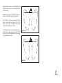
NOTA: Para activar el funcionamiento inverso de
este ventilador, pulse el botón reverse (invertir)
mientras está en marcha.
Clima cálido - (Hacia adelante) Un movimiento
descendente de aire crea un efecto de enfriamiento
cómo se musetra en la Figura 20. Esto permite fijar el
aire acondicionado en un valor más alto sin afectar la
comodidad del usuario.
Clima frío - (Retroceso) Un flujo de aire ascendente
mueve el aire caliente alejándolo del área del techo
cómo se muestra en la Figura 21. Esto permite fijar la
unidad de calefacción en un valor más bajo sin afectar
la comodidad usuario.
Figura 20
Figura 21
12.

He aqui algunas sugerencias para ayudarle el
mantenimiento del ventilodor.
1. Debido al movimiento natural del ventilador,
algunas conexiones se podrian aflojar. Examinar las
conexiones del soporte, soportes, y accessorios de las
aspas dos veces al año. Asgurarse de que estén
seguros. (No es necesario retirar el venitlador del
techo).
2. Limpiar el ventilador periódicamente para ayudar a
mantener su apariencia de nuevo con el transcurso del
tiempo. Usar solamente un cepillo suave o paño sin
hilas para evitar rayar el acadado. El recubrimiento
metálico se sella con una laca para minimizar la
decoloración o manchado. No usar agua al limpiarlo.
madera, o posiblemente causar choque eléctrico.
3. Se puede aplicar una capa ligera de pulidor para
muebles a las aspas de madera para brindar protección
adicional y realzar su belleza. Cubrir los rayones
pequeños con una ligera aplicación de betún para
calzado.
4. No hay necesidad de aceitar el ventilador. El motor
tiene cojinetes permanentemente lubricados.
ADVERTENCIA
ASEGURARSE DE QUE LA ELECTRICIDAD
ESTÉ DESACTIVADA EN EL TABLERO DE
DISTRIBUCIÓN ELÉCTRICA ANTES DE
INTENTAR CUALQUIER REPARACIÓN
REFERIRSE A LA SECCIÓ "CÓMO
EFECTUAR CONEXIONES ELÉCTRICAS"
13.
Cómo cuidar del ventilador

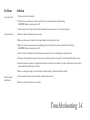
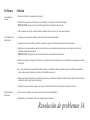
Solución
1. Revisar los fusibles o interruptores de circuitos.
2. Verificar las conexiones de cables de linea al ventilador y conexiones de cable del interruptor.
PRECAUCIÓN: Asegurarse de que la fuente pricipal de electricidad esté desactivada.
3. Check to make sure the dip switches from the transmitter and receiver are set to the same frequency.
1. Asegurarse de que todos los tornillos de la cubierta del motor estén ajustados.
2. Asegurarse de que los tornillos que sujetan el soporte de aspas del ventilador al eje del motor estén apretados.
3. Asegurarse de que las conexiones de tuercas para cable no esten rozando unas contra otras o contra la pared interior de la
cubierta protectora del interruptor.
PRECAUCIÓN: Asegurarse de que la fuente principal de electricidad esté desactivada.
4. Permitir un período de "desgaste" de 24 horas. La moyaría de los ruidos asociados con un ventilador nuevo desaparecen durante
este tirmpo.
5. Si se está usando un juego opcional de iluminación para el venitlador de techo, aseguarse de que los tornillos que aseguran el
vidrio estén apretados. Asimsmo, verificar que la bombilla esté seg ura.
6. Algunos motores son señsibles a las señales provenientes de controles de velocidad variable de estado sólido. Si tiene instalado
este tipo de control, elegir e instalar otro tipo.
7. Asegurarse de que el escudete superior esté a una corta distancia del techo. No debe hacer contacto con el techo.
1. No conecte el ventilador con un control en la pared de velocidad variable (s)
2. Compruebe que el interruptor oculto esté configurado correctamente.
Problema
El ventilador no
arranca.
El ventilador hace
mucho ruido.
Fallo del mando
a distancia
Resolución de problemas
14.

2017 Progress Lighting, Inc.
701 Millennium Blvd.,
Greenville, SC 29607
All Rights Reserved
c
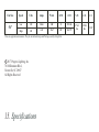
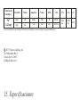
15.
Especificaciones
17.41
lbs
19.84
lbs
2.10'
Tamaño del
Ventilador
Velocidad Voltios
Amperios
Vatios
RPM CFM N.W. G.W. C.F.
56"
(142 cm)
Baja
Alta
120
120
Estas son mediciones aproximadas. No incluyen los Amperios y vatios usado por el juego de iliminación.
0.046
0.43
2.08
32.67
53
159
1951.56
6767.71
-
 1
1
-
 2
2
-
 3
3
-
 4
4
-
 5
5
-
 6
6
-
 7
7
-
 8
8
-
 9
9
-
 10
10
-
 11
11
-
 12
12
-
 13
13
-
 14
14
-
 15
15
-
 16
16
-
 17
17
-
 18
18
-
 19
19
-
 20
20
-
 21
21
-
 22
22
-
 23
23
-
 24
24
-
 25
25
-
 26
26
-
 27
27
-
 28
28
-
 29
29
-
 30
30
-
 31
31
-
 32
32
-
 33
33
-
 34
34
-
 35
35
-
 36
36


Progress Lighting P2570-09 Guía de instalación
- Categoría
- Ventiladores domésticos
- Tipo
- Guía de instalación
En otros idiomas
Documentos relacionados
-
Progress Lighting P2548-0930K Guía de instalación
-
Progress Lighting P2562-20 Instrucciones de operación
-
-
Progress Lighting P250095 Manual de usuario
-
-
-
-
-
-