Aire a Minka Group Design 04661 Instrucciones de operación
- Categoría
- Ventiladores domésticos
- Tipo
- Instrucciones de operación

INSTRUCTION MANUAL WARRANTY CERTIFICATE
READ AND SAVE ALL INSTRUCTIONS
TIDAL BREEZE

2
This product is protected by United States Federal and/or State Law, including Patent, Trademark and/or Copyright laws.
Manual design and all elements of manual design are protected by U.S. Federal and/or State Law, including Patent,
Trademark and/or Copyright laws.
1151 W. Bradford Court, Corona, CA 92882 For Customer Assistance Call: 1-800-307-3267

3
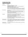
The Aire warranty is for one (1) year from the date of purchase from an authorized Aire dealer. This warranty is only
valid to the original purchaser or user against all defects in material and workmanship (light bulbs excluded) for one (1)
full year. Additionally, Aire warrants the motor only for the lifetime of the Aire ceiling fan (excluding wall controls and
electrical components), to the original purchaser or user.
To obtain warranty service during the warranty period, the purchaser should return the fan with the original sales
receipt to the original place of purchase. Replacement is subject to availability of the same model. This is a limited
warranty; the original purchaser or user is responsible for the cost of removal and re-installation of repaired or
replacement product. Outdoor finishes are specifically excluded from the terms of this warranty since they are subject
to environmental and maintenance damages beyond our control.
Fan warranty registration should be mailed as addressed on the warranty card.
• The warranty is void with the use of any non-Aire electrical devices; e.g., wall controls or electrical dimmer switches,
etc.
• The warranty is void once the original purchaser or user ceases to own the fan or the fan is moved from its original
point of installation.
• The warranty is void with the use of any hanger bracket (non-Aire or non-fan specific) other than the hanger bracket
supplied in the box.
• The warranty is void if installed in an environment other than its intended use (Indoor fans installed outdoors or in a
covered outdoor patio area, or subjected to environmental conditions: salt air, humidity, direct sun exposure, etc.).
Outdoor finishes are specifically excluded from the terms of this warranty since they are subject to environmental
and maintenance damages beyond our control.
WARRANTY SERVICE INFORMATION
WARRANTY
Date Purchased Store Purchased Model Number
04661 04662
Serial Number
CONTENTS
SAFETY RULES............................................................................
PACKAGE CONTENTS...................................................................
INSTALLING THE FAN...................................................................
HANGING THE FAN.......................................................................
ELECTRICAL CONNECTIONS.........................................................
FINISHING THE INSTALLATION...............................................
ATTACHING THE FAN BLADES......................................................
ATTACHING THE UP HOUSING......................................................
INSTALLING THE 14.5W LED ASSEMBLY................................
OPERATING THE REMOTE CONTROL......................................
CARE OF YOUR FAN...............................................................
TROUBLESHOOTING...............................................................
SPECIFICATIONS...................................................................
4
5
6
7
7
8
9
10
11
12
13
14
15

4
SAFETY RULES
1. To reduce the risk of electric shock, ensure electricity has been turned off at the circuit breaker or fuse box before
beginning.
2. All wiring must be in accordance with the National Electrical Code “ANSI/NFPA 70-1999” and local electrical codes.
Electrical installation should be performed by a qualified licensed electrician.
3. The outlet box and support structure must be securely mounted and capable of reliably supporting a minimum of 35
lbs. Use only UL-listed outlet boxes marked “FOR FAN SUPPORT.”
4. The fan must be mounted with a minimum of 7 ft. clearance from the trailing edge of the blades to the floor.
5. Avoid placing objects in the path of the blades.
6. To avoid personal injury or damage to the fan and other items, be cautious when working around or cleaning the fan.
7. Do not use water or detergents when cleaning the fan or fan blades. A dry dust cloth or lightly dampened cloth will
be suitable for most cleaning.
8. After making electrical connections, spliced conductors should be turned upward and pushed carefully up into the
outlet box. The wires should be spread apart with the grounded conductor and the equipment-grounding conductor
on one side of the outlet box and ungrounded conductor on the other side of the outlet box.
9. All setscrews must be checked and retightened where necessary before installation.
10. Turn the fan off and wait for the blades to stop completely before performing any maintenance or cleaning.
NOTE: The important safeguards and instructions appearing in this manual are not meant to cover all possible
conditions and situations that may occur. It must be understood that common sense, caution and care are factors which
cannot be built into this product. These factors must be supplied by the person (s) installing, caring for and operating
the unit.
WARNING
TO REDUCE THE RISK OF FIRE, ELECTRIC SHOCK, OR OTHER PERSONAL INJURY, MOUNT FAN ONLY ON AN OUTLET BOX OR
SUPPORTING SYSTEM MARKED ACCEPTABLE FOR FAN SUPPORT OF 35 LBS (15.9 KG) OR LESS AND USE MOUNTING
SCREWS PROVIDED WITH THE OUTLET BOX. MOST OUTLET BOXES COMMONLY USED FOR THE SUPPORT OF LIGHTING
FIXTURES ARE NOT ACCEPTABLE FOR FAN SUPPORT AND MAY NEED TO BE REPLACED. CONSULT A QUALIFIED ELECTRICIAN
IF IN DOUBT.
TO REDUCE THE RISK OF PERSONAL INJURY, DO NOT BEND THE BLADE HOLDERS WHILE INSTALLING, BALANCING THE
BLADES OR CLEANING THE FAN. DO NOT INSERT FOREIGN OBJECTS BETWEEN ROTATING FAN BLADES.
TO REDUCE THE RISK OF FIRE OR ELECTRONIC SHOCK, THIS FAN ONLY CAN USE DL-1167RYS-02 SOLID-STATE SPEED CONTROL
WITH DL-4112S-04 REMOTE CONTROL ONLY.
ATTENTION: The Energy Policy Act of 2005 requires this fan to be equipped with a 190 watt limiting device. If lamping
exceeds 190 watts, the ceiling fan's light kit will shut off automatically.

5
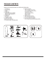
A. Mounting hardware:
#10 x 1.5" Wood screws (2 PCs.)
#8 x 3/4" Machine screws (2 PCs.)
Lock washers (2 PCs.)
4mm Star washers (2 PCs.)
Wire nuts (3 PCs. )
Washers (2 PCs.)
B. Blade attachment hardware:
1/4" x 15.8 mm Screws (13 PCs.)
C. Up housing attachment hardware:
1/4" x 9.5 mm Screws with lock washers (6 PCs.)
1. Fan blades (3)
2. Hanger bracket
3. Canopy
4. Canopy cover
5. Standard downrod assembly(6")
Minimum-length downrod(4.5")
6. Coupling cover
7. Up housing
8. Fan motor assembly
9. 14.5W LED assembly
10. Receiver with 6 wire nuts
11. Transmitter+holder+2 mounting screws
PACKAGE CONTENTS
Unpack your fan and check the contents. You should have the following items:
2 6
7
8
9
3
4
5
10
11
1
B
A
C

6
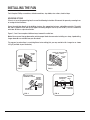
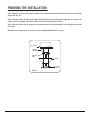
INSTALLING THE FAN
Tools Required: Phillips screw driver; slotted screw driver; step-ladder; wire cutters; electrical tape.
MOUNTING OPTIONS
If there isn't an existing mounting box, then read the following instructions. Disconnect the power by removing fuses
or turning off circuit breakers.
Secure the outlet box directly to the building structure. Use appropriate fasteners and building materials. The outlet
box and its support must be able to fully support the moving weight of the fan (at least 50 lbs.). Use a UL Listed metal
outlet box. Do not use a plastic outlet box.
Figure 1, 2 and 3 are examples of different ways to mount the outlet box.
CEILING
JOIST
FIG. 1
CROSS
BRACE
CEILING
JOIST
CEILING
JOIST
OUTLET BOX
OUTLET BOX
FIG. 2
PARALLEL WOOD BRACE
(MIN. 2" THICK)
OUTLET
BOX
CEILING JOIST OR
CROSS BRACE
FIG. 3 FIG. 4
ANGLED CEILING
MAXIMUM 18° ANGLE PROVIDE
STRONG
SUPPORT
RECESSED
OUTLET BOX
HANGER
OPENING
MUST BE
FACING
UPSIDE
HANGER BAR
(OPTIONAL)
HANGER
BRACKET
Note: You may need a longer downrod to maintain proper blade clearance when installing on a steep, sloped ceiling.
Longer downrods are available from your Aire dealer.
To hang your fan where there is an existing fixture but no ceiling joist, you may need to install a hanger bar as shown
in Fig. 4 (available at your Aire dealer).

7
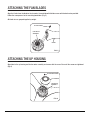
ATTACHING THE FAN BLADES
Align the 4 holes from the blade to the fan motor. Secure blade with 4 blade screws with locked washer provided.
Follow the same process for the remaining two blades. (Fig. 5)
All blade sets are grouped together by weight.
ATTACHING THE UP HOUSING
Align holes in the up housing and the fan motor assembly, and secure with the screw. Ensure all the screws are tightened.
(Fig. 6)
FIG. 5
BLADE
BLADE SCREW
FAN MOTOR
ASSEMBLY
FIG. 6
UP HOUSING SCREW
UP HOUSING
FAN MOTOR
ASSEMBLY

8
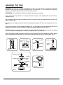
HANGING THE FAN
REMEMBER to turn off the power. Follow the steps below to hang your fan properly:
Step 1. Secure the Hanger Bracket to the ceiling outlet box using the screws provided with your outlet box in
conjunction. (Fig. 7)
Step 2. Loosen the two Set Screws and remove the Hitch Pin and Lock Pin from the coupling located on the top of the
Motor Assembly. (Fig. 8)
Step 3. Remove the Hanger Ball from the Downrod Assembly by loosening the Set Screw and removing the Cross Pin.
(Fig. 9)
Step 4. Carefully feed fan wires up through the downrod. (Fig. 10) Thread Downrod into the Coupling until the holes are
lined up and secure with the Lock Pin and Hitch Pin previously removed, tighten Set Screws. (Fig. 11)
Step 5. Slip coupling cover, canopy cover and canopy onto downrod. (Fig. 11) Carefully reinstall hanger ball onto rod being
sure that cross pin is in correct position, set screws are tighten and wires are not twisted.
Step 6. Lift the Motor Assembly and place the Hanger Ball into the Hanger Bracket. Rotate the Motor Assembly as needed
until the check groove from the Hanger Ball rests firmly over the registration tab from the Hanger Bracket. (Fig. 12)
FIG. 7
FIG. 11
FIG. 12
OUTLET BOX
HANGER BRACKET
DOWNROD
SUPPLY
WIRES
REGISTRATION
SLOT
CROSS PIN
HANGER
BALL
DOWNROD
HITCH
PIN LOCK
PIN
SET SCREWS
SET SCREW
DOWNROD
CANOPY
HITCH PIN
LOCK PIN
COUPLING COVER
SET SCREWS
CANOPY
COVER
FIG. 8 FIG. 9 FIG. 10
WARNING: All of the parts, hardware and components such as the hanger bracket and hanger ball have been
provided for your safety and the proper installation of your new ceiling fan. The use of other parts, hardware or
components not supplied by Aire with the fan will void the Aire Warranty.

9
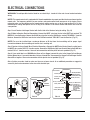
ELECTRICAL CONNECTIONS
WARNING: To avoid possible electrical shock be sure electricity is turned off at the main fuse or breaker box before
wiring.
NOTE: This remote control unit is equipped with 16 code combinations to prevent possible interference from or to other
remote units. The frequency switches on your receiver and remote control have been preset at the factory. Please
recheck to make sure the switches on the remote control and the receiver are set to the same position (Fig. 13). Any
combination of settings will operate the fan as long as the switches in the remote control and receiver are set to the
same position.
Step 1. Insert Receiver into Hanger Bracket with the flat side of the Receiver facing the ceiling. (Fig. 14)
Step 2. Motor to Receiver Electrical Connections: Connect the WHITE wire from the fan to the WHITE wire marked "TO
MOTOR N" from the Receiver. Connect the BLACK wire from the fan to the BLACK wire marked "TO MOTOR L" from the
Receiver. Connect the BLUE wire from the fan to the BLUE wire marked "FOR LIGHT" from the Receiver. (Fig. 15)
NOTE: Fan must be installed from a maximum distance of 40 feet from the transmitting unit for proper signal
transmission between the transmitting unit and the fan's receiving unit.
Step 3. Receiver to House Supply Wires Electrical Connections: Connect the WHITE wire (Neutral) from the outlet box to
the WHITE wire marked "AC in N" from the receiver. Connect the BLACK wire (Hot) from the outlet box to the BLACK wire
marked "AC in L" from the receiver. Secure all wire connections with the plastic wire nuts provided. (Fig. 15)
Step 4. If your outlet box has a GROUND wire (Green or Bare Copper) connect this wire to the Hanger Ball and Hanger
Bracket Ground wires. If your outlet box does not have a Ground Wire, then connect the Hanger Ball and Hanger Bracket
Ground Wires together. Secure wire connection with the plastic wire nut provided. (Fig. 15)
After all splices are made, check to make sure there are no loose strands. As an additional precaution we suggest to
secure the plastic wire connectors to the wires with electrical tape.
FIG. 13 FIG. 14 FIG. 15
RECEIVER
HANGER
BRACKET
WHITE (NEUTRAL)
WHITE (NEUTRAL)
GREEN OR BARE
COPPER (GROUND)
WHITE ("AC IN N")
WHITE ("TO MOTOR N")
GROUND-
(GREEN)
(CONNECT TO
GROUND WIRE ON
HANGER BRACKE
IF NO HOUSE
GROUND WIRE
EXISTS.)
OUTLET BOX
BLACK (HOT)
BLACK ("AC IN L")
BLACK ("TO MOTOR L")
RECEIVER
BLUE (FOR LIGHT)
BLUE (FOR LIGHT)
BLACK (MOTOR)

10
FINISHING THE INSTALLATION
Step 1. Remove 1 of the 2 screws from the bottom of the hanger bracket and loosen the other one half a turn from the
screw head. (Fig. 16)
Step 2. Slide the canopy up towards the hanger bracket and place the key hole on the canopy over the screw on the
hanger bracket, turn canopy until it locks in place at the narrow section of the key holes.
Step 3. Align the circular hole on canopy with the remaining hole on the hanger bracket, secure by tightening the two
set screws.
Note: Adjust the canopy screws as necessary until the canopy and canopy cover are snug.
OUTLET BOX
HANGER
BRACKET
HANGER
BALL
CANOPY
CANOPY
COVER
FIG. 16

11
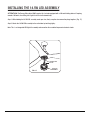
INSTALLING THE 14.5W LED ASSEMBLY
Step 1. While holding the 14.5W LED assembly under your fan, rmly snap the wire connection plugs together. (Fig. 17)
Step 2. Attach the 14.5W LED assembly to the switch box by twisting tightly .
Note: This is an integrated LED light kit assembly and cannot be disassembled to prevent electronic shock.
14.5W LED
ASSEMBLY
CONNECTION
PLUGS
ATTENTION: The Energy Policy Act of 2005 requires this fan to be equipped with a 190 watt limiting device. If lamping
exceeds 190 watts, the ceiling fan's light kit will shut off automatically.
FIG. 17

12
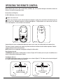
OPERATING THE REMOTE CONTROL
Remote Control only: Install a A23 12 volt battery (included). (Fig. 18) To prevent damage to transmitter remove the
battery if not used for long periods of time.
Restore Power to Ceiling Fan.
HI, MED, LOW buttons: Sets the fan speed.
button: Turns the fan off.
button: Turns the light on or off and also controls the brightness setting. Press and release this button to turn the
light on or off. Press and hold the button to set the desired brightness. The light button has an auto-resume, it will stay
at the same brightness as the last time it was turned off.
FIG. 18 FIG. 19
Speed settings for warm or cold weather depend on factors such as room size, ceiling height and number of fans.
The Reverse switch is located on the switch cup. Slide the switch to the Down for warm weather operation. Slide the
switch to the Up for cool weather operation.
NOTE: Wait for fan to stop before changing the setting of the slide switch.
Warm Weather (forward)
A DOWNWARD airflow creates a cooling effect as shown in Figure 20. This allows you to set your air conditioner on a
warmer setting without affecting your comfort.
Cool Weather (Reverse)
An UPWARD airflow moves warmer air off the ceiling area as shown in Figure 21. This allows you to set your heating unit
on a cooler setting without affecting your comfort.
FIG. 20 FIG. 21
SUMMER OPERATION
COUNTER CLOCKWISE CLOCKWISE
WINTER OPERATION

13
CARE OF YOUR FAN
Here are some suggestions to help maintain your fan.
1. Because of the fan's natural movement some connections may become loose. Check the support connections,
brackets and blade attachments twice a year. Make sure they are secure. (It is not necessary to remove fan from the
ceiling).
2. Clean your fan periodically to help maintain its new appearance over the year. CAUTION: many common household
cleaning products contain chemicals that could damage the finish of your fan. Use only a soft lint free cloth and soapy
water.
3. If your fan is provided with wood veneer blades; you can apply a light coat of furniture polish for additional protection
and enhanced beauty. Cover small scratches with a light application of shoe polish.
4. Use a lint free lightly damp cloth or duster to remove dust from the blades.
5. There is no need to oil your fan. The motor has permanently lubricated bearings.
6. If your fan is provided with glass shades, clean with lukewarm soapy water and a soft cloth or sponge. DO NOT
IMMERSE GLASS SHADES IN HOT WATER. DO NOT PUT GLASS SHADES INTO AN AUTOMATIC DISHWASHER.
WARNING!
MAKE SURE THE POWER IS OFF AT THE ELECTRICAL PANEL BOX BEFORE YOU ATTEMPT ANY REPAIRS. REFER TO
THE SECTION, "ELECTRICAL CONNECTIONS".

14
TROUBLESHOOTING
Check to make sure the wall switch is turned on.
Check circuit fuses or breakers.
Caution! Make sure the power is turned off before performing the following steps.
Remove canopy and check wire connections.
Check wall control transmitter connections (if applicable).
Note: Fan must be installed at a maximum distance of 40 feet from the transmitting unit
for proper signal transmission between the transmitting unit and the fan's receiving unit.
Allow a 24-hour "break in" period. Most noises associated with a new fan will go away
during this time.
Make sure the screws that attach the fan blade holder to the motor hub is tight.
Make sure outlet box is secured to building structure, if necessary use the wood screws
provided to further secure outlet box to joist.
Make sure hanger bracket is secure to the outlet box, screws are tight.
NOTE: All blade sets are grouped by weight. Because wood and plastic blades vary in
density, the fan may wobble even though blades are matched.
Make sure outlet box is secured to building structure, if necessary use the wood screws
provided to further secure outlet box to joist.
Make sure hanger bracket is secure to the outlet box, screws are tight.
If a Balancing kit is provided follow the instructions included with the balancing kit to
help correct any excessive wobble.
This unit is equipped with a wattage limiting device. Lamping in excess of 190 watts will
disable your ceiling fan’s light kit. To reset your light kit you must turn the power off and
re lamp, keeping the wattage under 190 watts. Restore power to your ceiling fan and
continue normal operation.
This is caused by interference, Please see "Frequency interference" for steps to change
the frequency.
Fan will not start
Fan Sounds Noisy
Fan Wobble
Lights shut off and
will not come back on
Fans/Light Turn On
and Off Unexpectedly
SOLUTION
SYMPTOM

15
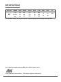
SPECIFICATIONS
1151 W. Bradford Court, Corona, CA 92882 For Customer Assistance Call: 1-800-307-3267
For any additional information about your Minka Aire® Ceiling fan, please write to:
These are typical readings. Your actual fan may vary. They do not include amps and wattage used by the light(s).
56" 120
120
120
Fan Size Speed Volts
Low
Medium
High
N.W.
7.0
kgs
G.W.
8.4
kgs
Amps
0.27
0.40
0.54
Watts
15.5
35.0
64.0
RPM
69
108
157
CFM
3283
5519
6986
C.F.
1.529'

MANUAL DE INSTRUCCIONES CERTIFICADO DE GARANTIA
LEER Y GUARDE TODAS LAS INSTRUCCIONES
TIDAL BREEZE

2
Este producto esta protegido por la Federal de los Estados Unidos y/o del Estado de Derecho, incluyendo patentes, marcas
y/o leyes de derecho de autor.
Diseño del manual y todos los elementos del diseño de manual están protegidos por EE.UU. y / o federales del Estado de
Derecho, incluyendo patentes, marcas y / o derechos de autor.
1151 W. Bradford Court, Corona, CA 92882 For Customer Assistance Call: 1-800-307-3267

3
04661 04662
Para obtener servicio de garantía durante el período de garantía, el comprador debe devolver el ventilador con el
recibo original de compra al lugar original de compra. Reemplazo está sujeto a la disponibilidad del mismo modelo. Esta
es de una garantía, el comprador original o usuario es responsable por el costo de quitar y reinstalar del producto
reparado o reemplazado. Acabados exteriores están específicamente excluidos de los términos de esta garantía, ya que
sonsujetos a daños ambientales y de mantenimiento fuera de nuestro control.
Registro de la garantía para la banico puede ser enviada por correo ya abordado en la tarjeta de garantía.
La garantía de Aire es de un (1) año a partir de la fecha de compra de un distribuidor autorizado de Aire. Esta
garantía sólo es válida para el comprador original o al usuario contra cualquier defecto de material y mano de obra
(focos no incluidos) por (1) año completo. Además, Aire garantiza por vida el motor del ventilador de techo unicamente
por vida (con exclusión de los controles de la pared y componentes eléctricos), al comprador original o al usuario.
• La garantía queda anulada con el uso de los euipos eléctricos que no son de Aire, controles de ejemplo, interruptores
de pared o interruptores eléctricos regulador, etc.
• La garantía no es válida una vez que el comprador original o el usuario deja de poseer el ventilador o el ventilador se
mueve desde su punto de instalación original.
• La garantía es vacía con demandar de cualquier soporte de su spensión (non-Aire o no abanico específico) además
del soporte de suspensión suministrado e instalado con esta abanico específicamente.
• La garantía no es válida si se instala en un entorno que no sea el uso previsto (ventiladores interiores instalados al
aire libre o en un patio cubierto al aire libre, osometido a las condiciones ambientales: aire sal, humedad, exposición
directa al sol, etc.). Acabados exteriores están específicamente excluidos de los términos de estegarantía ya que
están sujetos a los daños ambientales y de mantenimiento fuera de nuestro control.
INFORMACIÓN DE SERVICIO DE GARANTÍA
GARANTÍA
Fecha de Compra Tienda Donde Lo Compro Num. De Modelo
Num. De Serie
ÍNDICE
NORMAS DE SEGURIDAD............................................................
CONTENIDO DEL PAQUETE..........................................................
COMENZANDO LA INSTALACION.................................................
COLGANDO EL VENTILADOR........................................................
CONEXIONES ELECTRICAS..........................................................
TERMINANDO LA INSTALACION.............................................
INSTALACION DE LAS CARCASA.................................................
INSTALACION DE LAS ASPAS......................................................
INSTALACIÓN DEL CONJUNTO LED 14.5W.............................
OPERACION DEL CONTROL REMOTO ....................................
MANTENIMIENTO DE SU VENTILADOR...................................
SOLUCION DE PROBLEMAS...................................................
ESPECIFICACIONES...............................................................
4
5
6
7
7
8
9
10
11
12
13
14
15

4
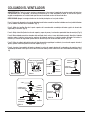
NORMAS DE SEGURIDAD
1. Precaucion; Para reducir el riesgo de una electrocucion, asegurese de desconectar la corriente electrica sacando
los fusibles o apagando el circuito central.
2. !Sea Cuidadoso!; Lea el manual de instrucciones y la informacion de las reglas de seguridad antes de comenzar la
instalacion de su ventilador. Revise bien los diagramas de ensamble proveidos en este manual.
3. Asegurese que todas las conexiones electricas cumplan con los Codigos Electricos Locales y Nacionales. Si usted
no esta familiarizado con la instalacion de alambrados electricos, contrate a un electricista calificado o consulte en
un manual de como hacerlo usted mismo.
4. Asegurese que el lugar que escoja para la instalacion del ventilador permita que las aspas giren sin obstruccion.
Permita un margen de espacio minimo de 7 pies entre el bordo mas bajo de las aspas y el piso y 18 pulgadas entre
las puntas de las aspas y la pared.
5. La caja de distribucion y el soporte de la estructura del edificio deben estar firmemente instalados y capaces de
soportar el peso en movimiento del ventilador (minimo de 50 libras). La caja de distribucion debe estar aprovada
por UL y marcada "Acceptable for Fan Support" no use cajas de distribucion de plastico.
6. Cuidado; Asegure la abrazadera de montaje utilizando los tornillos proveidos con la caja de distribucion y las
arandelas proveidas con el ventilador.
7. Si esta montando el ventilador en una viga, asegurese que pueda soportar el peso del ventilador en movimiento
(minimo de 50 libras).
8. Despues de colgar el ventilador asegurese una ves mas que todas las partes esten firmemente apretandas.
9. No inserte ningun objeto entre las aspas cuando el ventilador este en operacion.
10. Apague el ventilador y espere hasta pare por completo antes de proceder con la limpieza o mantenimiento.
ATENCIÓN: La Ley de Póliza Energética de 2005 requiere que este ventilador este equipado con una limitación de 190
vatios dispositivo. Si el uso de luz supere los 190 vatios, el ensamblaje de luz del ventilador de techo se apagará
automáticamente.
NOTA: Las importantes reglas de seguridad e instrucciones que aparecen en este manual no signfican el cubrimiento
de todas las posibles condiciones y situaciones que se puedan presentar. Se debe entender que el sentido comun,
precauciones y cuidado son factores que no se pueden incluir en este producto. Estos factores deben de ser
suministrados por la(s) persona(s) que instalen, cuiden y operen el ventilador.
ADVERTENCIA
PARA REDUCIR EL RIESGO DE INCENDIO, DESCARGA ELÉCTRICA O LESIONES FÍSICAS, SÓLO INSTALA EL VENTILADOR EN
UNA CAJA ELÉCTRICA O SISTEMA DE SOPORTE APROBADOS PARA VENTILADORES DE 35 LB (15,9 KG) O MENOS, Y USA LOS
TORNILLOS DE MONTAJE QUE VIENEN CON LA CAJA ELÉCTRICA. LA MAYORÍA DE LAS CAJAS ELÉCTRICAS COMÚNMENTE
USADAS PARA EL SOPORTE DE LÁMPARAS NO SON ACEPTABLES PARA SOPORTE DE VENTILADOR Y PUEDEN NECESITAR UN
REEMPLAZO. SI TIENES DUDAS, CONSULTA A UN ELECTRICISTA CALIFICADO.
PARA REDUCIR EL RIESGO DE LESION PERSONAL, NO DOBLE LAS ASPAS DURANTE LA INSTALACION, BALANCEO O LIMPIEZA
DE LAS ASPAS. NO INTRODUSCA OBJETOS EXTRAÑOS ENTRE LAS ASPAS MIENTRAS EL VENTILADOR ESTE EN OPERACION
MONTE DIRECTAMENTE EN LA ESTRUCTURA DEL EDIFICIO.
PARA REDUCIR EL RIESGO DE INCENDIO O DESCARGA ELÉCTRICA, ESTE VENTILADOR SÓLO SE PUEDE UTILIZAR DL-1167RYS-02
CONTROL DE VELOCIDAD DE ESTADO SÓLIDO CON DL-4112S-04 CONTROL REMOTO SOLAMENTE.
ADECUADO PARA USO EN LUGARES HUMEDOS O MOJADOS.

5
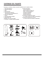
A. Hardware de montaje:
Tuercas de alambre (3)
#8x3/4" Tornillos de la máquina (2)
#10x1.5" Tornillos de madera (2)
Arandelas de seguridad (2)
Arandelas de estrella (2)
Arandelas de metálica (2)
B. Partes para la instalacion de las aspas:
1/4" x15.8mm Tornillos con arandelas de sequridad (13)
C. Partes para la instalacion de las carcasa:
1/4" x9.5mm Tornillos con arandelas de sequridad (6)
1. Aspas del Ventilador (2)
2. Soporte de suspensión
3. Dosel
4. Cubierta de dosel
5. Tubo de montaje estandar (6")
Tubo de montaje de longitud minima (3.5")
6. Cubierta de acoplamiento
7. Carcasa
8. Conjunto de motor de ventilador
9. Conjunto LED 14.5W
10. Receptor con 6 tuercas de alambre
11. Transmisor + sujetador+2 tornillos de montaje
CONTENIDO DEL PAQUETE
Desempaque su ventilador y verifique el contenido. Usted debera tener los siguientes articulos:
2 6
7
8
9
3
4
5
10
11
1
B
A
C

6
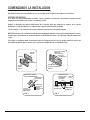
COMENZANDO LA INSTALACION
Herramientas Necesarias: Desarmador de cruz, desarmador plano, cortadoras de alambre y cinta aislante.
OPCIONES DE MONTAJE
Si no existe una caja de distribucion instalada, siga las siguientes instrucciones. Desconecte la energia electrica
apagando los interruptores del circuito o sacando los fusibles.
Asegure la abrazadera de montaje directamente de la viga del techo por medio de los agujeros de la caja de
distribucion. La viga del edificio y sus soportar todo el peso en movimiento del ventilador.
Las ilustraciones 1, 2 y 3 muestran alternativas diferentes para montar la caja de distribucion.
NOTA: Podria necesitar un tubo de montaje de mayor longitud para obtener el espacio libre apropiado para las aspas,
cuando haga la instalacion en un techo con declive. Su distribuidor Aire tiene a su disposicion tubos de montaje mas
largos.
Para colgar su ventilador donde anteriormente habia una lampara pero no hay viga, prodria necesitar instalar una
abrazadera de soporte como se muestra en la ilustracion 4 (Disponible con su distribuidor Aire).
FIG. 1
PUNTAL
VIGA DE
TECHO
FIG. 2
FIG. 3 FIG. 4
CAJA DE
DISTRIBUCION
CAJA DE
DISTRIBUCION
PUNTAL DE MADERA
PARALELO
(MIN. 2" GRUESO)
VIGA DE TECHO O
PUNTAL ATRAVESADO
VIGA DE
TECHO
ABRAZADERA
DE MONTAJE
ABRAZADERA DE
SOPORTE PARA
SUSPENCION
(OPCIONAL)
VIGA DE
TECHO
CAJA DE
DISTRIBUCION
DECLIVE DEL TECHO
ANGULO MAXIMO DE 18°
PROPORCIONA
UN SOPORTE
FIRME
CAJA DE
DISTRIBUCION
EMPOTRADA
LA ABERTURA
DEL SOPORTE
DEBE DE
QUEDAR HACIA
AFUERA

7
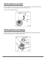
INSTALACION DE LAS ASPAS
Alinee los 4 agujeros de la aspa para el motor del ventilador. Asegure las aspas con los 4 tornillos de la cuchilla con la
arandela cerrada siempre. Siga el mismo proceso para la otras dos aspas. (Fig. 5)
Todas las aspas estan agrupadas por peso.
INSTALACION DE LAS CARCASA
Alinear los agujeros en el carcasa y el juego de ensamblaje del motor del ventilador, y je por el tornillo al motor.
Asegúrese de que todos los tornillos están bien apretados. (Fig. 6)
FIG. 5
ASPA
TORNILLOS
DE ASPA
CONJUNTO DE
MOTOR DE
VENTILADOR
FIG. 6
TORNILLO DE
CARCASA
CARCASA

8
FIG. 11
DOSEL
CUBIERTA DE
ACOPLAMIENTO CUBIERTA
DE DOSEL
COLGANDO EL VENTILADOR
ADVERTENCIA: Todas las partes, equipos y componentes, tales como el soporte de la percha y percha de bolas han
sido proveidos para su seguridad y la correcta Instalacion de su nuevo ventilador de techo. El uso de otras partes,
equipos o componentes no suministrados por Aire con el ventilador anulara la Garantia de Aire.
RECORDAR: Apagar la energia electrica en el circuito principal o en la caja de fusibles.
Paso 1. Asegure la abrazadera a la caja de distribucion del techo usando los tornillos incluidos con la caja de distribucion
y las arandelas incluidas con el ventilador. (Fig. 7)
Paso 2. Afloje los tornillos fijos de la parte superior de la conexion del ensamblaje del motor y quite la chaveta de
seguridad y la chaveta. (Fig. 8)
Paso 3. Afloje el tornillo fijo de la esfera de soporte y saque el perno y la esfera de soporte del tubo de montaje. (Fig. 9)
Paso 4. Meta cuidadosamente los alambres del ventilador hacia arriva a traves del tubo de montaje. Atornille el tubo de
montaje sobre el collarin hasta que los agujeros del tubo de montaje y el collarin queden alineados. Re-instale la
chaveta y la chaveta de seguridad. Apriete bien los tornillos fijos con un desarmador de cruz. (Fig. 10)
Paso 5. Delize la cubierta del collarin sobre el tubo de montaje seguida por la cubierta y la esfera de soporte. Instale el
perno y apriete el tornillo fijo de la esfera de soporte. (Fig. 11)
Paso 6. Levante el ensamblaje del motor y coloque la esfera de soporte dentro de la abrazadera de montaje, gire el
ensamblaje del motor hasta que la ranura de la esfera de montaje siente sobre estria de la abrazadera de montaje. (Fig.
12)
FIG. 7
FIG. 12
FIG. 8 FIG. 9 FIG. 10
ABRAZADERA DE
MONTAJE
CABLE DEL
VENTILADOR
CHAVETA
CHAVETA DE
SEGURIDED
TORNILLO
TUBO DE
MONTAJE
TUBO DE
MONTAJE
PERNO
CAJA DE DISTRIBUCION
ESFERA DE
SOPORTE
TORNILLOS DE SEGURIDAD
RANURA DE
REGISTRO
TUBO
TORNILLO FIJO
CHAVETA DE
SEGURIDAD CHAVETA

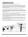
9
FIG. 13
CONEXIONES ELECTRICAS
RECORDAR: Apagar la energia electrica en el circuito principal o en la caja de fusibles.
NOTA: Esta unidad de control remoto tiene 16 combinaciones de códigos para evitar posibles interferencias con otras
unidades de control remoto. Los interruptores de frecuencia en tu receptor y control remoto han sido preconfigurados
en la fábrica. Revisa para asegurarte que los interruptores del control remoto y el receptor estén configurados en la
misma posición (Fig. 13). Cualquier combinación operará el ventilador mientras el control remoto y el receptor estén
configurados en la misma posición.
Paso 1. Instale el receptor en la abrazadera de montaje, el lado plano debe quedar hacia arriva. (Fig. 14)
Paso 2. Haga las conexiones del motor al receptor de la manera siguiente; Conecte el Alambre Blanco del ventilador al
alambre Blanco marcado "TO MOTOR N" del Receptor. Conecte el Alambre Negro del ventilador al alambre Negro
marcado "TO MOTOR L" del Receptor. Conecta el cable Azul del ventilador al cable Azul marcado como "FOR LIGHt"
(Para la Luz) del receptor. (Fig. 15)
NOTA: La distancia maxima para una recepcion apropiada entre el receptor del ventilador y el transmisor so 40 pies.
Asegurese que su ventilador sea instalado no mas de 40 pies de distancia del transmisor.
Paso 3. Haga las conexiones de la caja de distribucion a el Receptor de la manera siguiente; Conecte el Alambre blanco
(neutral) de la caja de distribucion al alambre blanco marcado "AC in N" del receptor. Conecte el Alambre Negro
(corriente) de la caja de distribucion al alambre Negro marcado "AC in L" del Receptor. Asegure las conexiones con los
conectores de plastico proveidos. (Fig. 15)
Paso 4. Si su caja de distribucion tiene un alambre a tierra (verde o cobre) conectelo a los alambres a tierra (verdes) de
la Esfera de Soporte y la Abrazadera de Montaje. Si su caja de distribucion no tiene un alambre a tierra, entonces
unicamente conecte los dos alambres a tierra de la Esfera de Soporte y la Abrazadera de Montaje. Asegure la conexion
con un conector de plastico proveido. (Fig. 15)
Despues de terminar las conexiones del alambrado, revise que no haiga hebras de alambre sueltas. Como una
precaucion mas, sugerimos que asegure los conectores de plastico a los alambres usando cinta aislante electrica.
FIG. 14 FIG. 15
ABRAZADERA
DE MONTAJE
RECEPTOR
BLANCO (NEUTRAL)
BLANCO (NEUTRAL)
BLANCO ("AC IN N")
BLANCO ("TO MOTOR N")
VERDE (A TIERRA)-
(CONECTE AL ALAMBRE A
TIERRA A LA ABRAZADERA
DE SOPORTE SI NO EXISTE
ALAMBRE A TERRA DE LA
CASA)
CAJA DE
DISTRIBUCION
NEGRO
(CON CORRIENTE)
NEGRO ("AC IN L")
NEGRO ("TO MOTOR L")
RECEPTOR
AZUL (LIGHT)
NEGRO (MOTOR)
AZUL ("FOR LIGHT")
VERDE O DE COBRE
(A TIERRA)

10
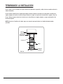
TERMINANDO LA INSTALACION
Paso 1. Quite 1 de los 2 tornillos de la parte inferior del soporte de suspensión y afloje el otro una media vuelta de la
cabeza del tornillo.
Paso 2. Deslice la dosel hacia el soporte para colgar y colocar el ojo de la cerradura en la copa sobre el tornillo en el
soporte colgante, de vuelta a la dosel hasta que encaje en su lugar en la parte más estrecha de los agujeros. (Fig. 16)
Paso 3. Alinee el agujero circular de la dosel con el otro orificio en el soporte colgante, asegure apretando los dos
tornillos de fijación.
NOTA: Ajuste los 2 tornillos de la dosel segun sea necesario para que la dosel y el cubierta de dosel queden
ajustados.
FIG. 16
CAJA DE
DISTRIBUCION
ABRAZADERA
DE MONTAJE
ESFERA
DOSEL
CUBIERTA
DE DOSEL

11
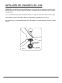
CONJUNTO
LED 14.5W
ENCHUFES DE
CONEXIÓN
ATENCIÓN: La Ley de Póliza Energética de 2005 requiere que este ventilador este equipado con una limitación de
190 vatios dispositivo. Si el uso de luz supere los 190 vatios, el ensamblaje de luz del ventilador de techo se apagará
automáticamente.
Paso 1. Sosteniendo la conjunto LED 14.5W bajo el ventilador, se encajan las clavijas de conexión de cables. (Fig.17)
Paso 2. Coloque la conjunto LED 14.5W a la placa caja del interruptor, y lo gitando con fuerza. (Fig.17)
Nota: Lo que trata es de un ensamblaje del juego de luz LED integrado y no se puede desmontar para evitar el choque
eléctrico.
FIG. 17
INSTALACIÓN DEL CONJUNTO LED 14.5W

12
FIG. 18 FIG. 19
FIG. 20 FIG. 21
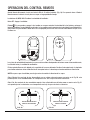
OPERACIÓN EN VERANO
SENTIDO ANTIHORARIO SENTIDO HORARIO
OPERACIÓN EN INVIERNO
OPERACION DEL CONTROL REMOTO
Control Remoto Unicamente: Instale una bateria A23 de 12 voltios (incluida). (Fig. 18) Para prevenir dano al Control
Remoto remueva la bateria si no lo piensa usar por un largo periodo de tiempo.
Los bottones HI, MED, LOW: Establece la velocidad del ventilador.
Boton OFF : Apaga el ventilador.
El boton : Es para prender y apagar la luz, tambien se usa para controlar la intensidad de la luz. Apriete y sostenga el
boton hasta obtener la intensidad de luz deseada. La luz cambiara continuamente entre intensidad y oscuridad mientras
que el boton esté presionado. El boton de la luz está equipado para resumir con la misma intensidad de luz que se uso
la ultima ves.
Los ajustes de velocidad o direccion de las aspas en clima calido o frio dependen de factores como el tamano del cuarto,
la altura del techo y la cantidad de ventiladores.
El Interruptor de Reversa está ubicado en la superficie de la carcasa del motor. Desliza el interruptor hacia a la izquierda
para funcionamiento en clima cálido. Desliza el interruptor hacia a la derecha para funcionamiento en clima fresco.
NOTA: espere a que el ventilador pare de girar antes de cambiar la direccion de las aspas.
Clima Caliente: Una corriente de aire descendiente crea un efecto refrescante como se muestra en la Fig. 20. esto
permite ajustar el aire acondicionado a un a temperatura mas alta sin que esto afecte su bienestar.
Clima Frio: Una corriente de aire ascendiente empuja el aire caliente del area del techo como se muestra en la Fig. 21
esto permite ajustar la calefaccion a una temperature mas baja sin que esto afecte su bienestar.

13
MANTENIMIENTO DE SU VENTILADOR
Las siguientes son sugerencias que le ayudaran en el mantenimiento de su ventilador.
1. Debido al movimiento natural del ventilador, es possible que algunas de las conexiones se aflojen o suelten. Revise
las conexiones que sostienen el ventilador, las abrazaderas y aspas por lo menos dos veces al año. Asegurese que todas
las conexiones siempre esten firmes y apretadas. (No es necesario bajar el ventilador del techo).
2. Limpie periodicamente su ventilador para que mantenga su apariencia de nuevo durante muchos años. CUIDADO:
muchos productos de limpieza comunmente usados en la casa contienen quimicas que podrian dañar el terminado de
su ventilador. Use un trapo suave que no deje pelusa y agua jabonosa.
3. Si su ventilador incluye aspas enchapadas de madera natural, puede aplicar una capa ligera de lustra muebles para
proteccion y para aumentar la belleza. Cubra las rayaduras pequenas con una ligera aplicacion de pasta para zapatos.
4. Use solamente un cepillo suave o un trapo que no suelte pelusa para evitar que se dañe el terminado.
5. No necesita aceitar su ventilador. El motor tiene baleros con lubricacion permanente.
6. Si su ventilador incluye pantallas de vidrio, limpielas usando agua tibia jabonosa y un trapo suave o una esponja. NO
SUMERJA EL VIDRIO EN AGUA CALIENTE, NO PONGA EL VIDRIO EN LA LAVADORA AUTOMATICA PARA LAVAR PLATOS.
ADVERTENCIA
ASEGURESE QUE LA ENERGIA ELECTRICA ESTE APAGADA ANTES DE INTENTAR HACER QUALQUIER REPARACION.
REFIERACE A LA SECCION "CONEXIONES ELECTRICAS".

14
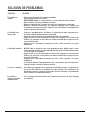
SOLUCION DE PROBLEMAS
Revise que el interruptor de la pared este prendido.
Revise los interruptores o los fusibles
RECUERDE: Apagar la energia electrica. Las aspas deben de estar instaladas.
Quite la cubierta y revise las conexiones electricas
Revise las conexiones del Transmisor de pared si esta incluido con su ventilador.
NOTA: La distancia maxima para una recepcion apropiada entre el receptor del
ventilador y el transmisor son 40 pies. Asegurese que su ventilador sea instalado no mas
de pies de distancia del transmisor.
Permita un "periodo de gracia" de 24horas. La mayoria de los ruidos asociados con un
ventilador nuevo desaparecen durante este periodo.
Revise que todos los tornillos del ensamblaje del motor esten apretados.
Asegurese que la caja de distribucion este firme y bien asegurada a la estructura del
edificio. Si es necesario use los tornillos para madera incluidos para asegurar mas aun
la caja de distribucion.
Asegurese que la abrazadera de montaje este firme y bien asegurada a la caja de
distribucion.
NOTA: Todos los juegos de aspas estan agrupados por peso. Debido a que las aspas
hechas de madera o plastico varian en densidad, puede que el ventilador tiemble aunque
las aspas tengan el mismo peso.
Asegurese que la caja de distribucion este firme y bien asegurada a la estructura del
edificio. Si es necesario use los tornillos para madera incluidos para asegurar mas aun
la caja de distribucion.
Asegurese que la abrazadera de montaje este firme y bien asegurada a la caja de
distribucion.
Si el juego de balanceo fue proporcionada siga las instrucciones que se incluyen con el
juego para ayudar a corregir el balanceo excesivo.
Esta unidad está equipada con un dispositivo de limitación de vatios. Uso de vatios en
exceso de 190 inhabilitara su ensamblaje de luz del ventilador. Para restablecer la luz
desconecte la corriente y corrija el uso de vatios. Restaure la corriente a su ventilador de
techo y continúe el funcionamiento normal.
This is caused by interference, Please see "Frequency interference" for steps to change
the frequency.
El ventilador no
arranca
El ventilador hace
mucho ruido
El ventilador tambalea
Las luces se apagaron
El ventilador o
lampara se prenden
repentinamente
SOLUCIÓN
PROBLEMA

15
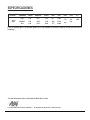
ESPECIFICACIONES
Estas son medidas tipicas. Su ventilador puede variar. Estas medidas no incluyen el amperaje o vatios que consumen la
lampara(s).
56" 120
120
120
Baja
Mediana
Alta
1151 W. Bradford Court, Corona, CA 92882 For Customer Assistance Call: 1-800-307-3267
Para mas infomacion sobre su Ventilador de Minka Aire® escriba:
Tamaño del
ventilador Velocidad Voltios
0.27
0.40
0.54
Amperios
15.5
35.0
64.0
Vatios
69
108
157
RPM
3283
5519
6986
CFM
7.0
kgs
N.W.
8.4
kgs
G.W.
1.529'
C.F.
-
 1
1
-
 2
2
-
 3
3
-
 4
4
-
 5
5
-
 6
6
-
 7
7
-
 8
8
-
 9
9
-
 10
10
-
 11
11
-
 12
12
-
 13
13
-
 14
14
-
 15
15
-
 16
16
-
 17
17
-
 18
18
-
 19
19
-
 20
20
-
 21
21
-
 22
22
-
 23
23
-
 24
24
-
 25
25
-
 26
26
-
 27
27
-
 28
28
-
 29
29
-
 30
30


Aire a Minka Group Design 04661 Instrucciones de operación
- Categoría
- Ventiladores domésticos
- Tipo
- Instrucciones de operación
en otros idiomas
Otros documentos
-
Minka Group F546-WH Manual de usuario
-
Progress Lighting P2514-09 Guía de instalación
-
-
-
-
-
-
Minka-Aire F745-DK Instrucciones de operación
-