
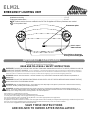
ELM2L
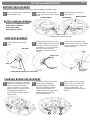
EMERGENCY LIGHTING UNIT
“TEST” button /
Status Indicator
Press latches to disengage
housing from mounting plate
Remote test option
Installation and wiring …………………..…………......…………………………………… P. 2-3
Testing and maintenance ………...…………………………………………………………P. 4-5
IMPORTANT SAFEGUARDS
When using electrical equipment, basic safety precautions
should always be followed, including the following:
!
!
!
!
!
READ AND FOLLOW ALL SAFETY INSTRUCTIONS
WARNING: FAILURE TO FOLLOW THESE INSTRUCTIONS AND WARNINGS MAY RESULT IN DEATH, SERIOUS INJURY OR
SIGNIFICANT PROPERTY DAMAGE - For your protection, read and follow these warnings and instructions carefully before installing or
maintaining this equipment. These instructions do not attempt to cover all installation and maintenance situations. If you do not understand
these instructions or additional information is required, contact Lithonia Lighting or your local Lithonia Lighting distributor.
WARNING: RISK OF ELECTRIC SHOCK – NEVER CONNECT TO, DISCONNECT FROM OR SERVICE WHILE EQUIPMENT IS
ENERGIZED.
WARNING: DO NOT USE ABRASIVE MATERIALS OR SOLVENTS. USE OF THESE SUBSTANCES MAY DAMAGE FIXTURE,
WHICH MAY RESULT IN PERSONAL INJURY.
WARNING: RISK OF PERSONAL INJURY – This product may have sharp edges. Wear gloves to prevent cuts or abrasions when removing
from carton, handling, installing and maintaining this product.
WARNING: The battery used in this device may present a risk of fire or chemical burn if mistreated. Do not disassemble, heat above 70° C
(158° F), or incinerate. Replace battery only as directed on the battery label and page 5 of these instructions. Use of unauthorized battery voids
warranty and UL listing of this product, and may present a risk of fire or explosion.
•Disconnect A.C. power before servicing.
•All servicing should be performed by qualified personnel.
•Consult your local building code for approved wiring and installation.
•Do not use outdoors unless used with Acuity Brands accessories appropriate to the application.
•Do not mount near gas or electric heater.
•Equipment should be mounted in locations and at heights where it will not readily be subjected to tampering by unauthorized personnel.
•The use of accessory equipment not recommended by the manufacturer may cause an unsafe condition.
•Do not use this equipment for other than intended use.
SAVE THESE INSTRUCTIONS
AND DELIVER TO OWNER AFTER INSTALLATION
NOTE: Product versions that are certified in the CA Title 20 Appliance Efficiency Database are marked
BC on the product label.

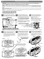
Orient conduit fitting so that
all portions of it clear the
edge of the knockout
Use washer (Grainger #4DAX6) between
conduit fitting and rear housing if
conduit fitting interferes with battery.
Figure-3
page 2
INSTALLATION and WIRING
1
2 3
On the mounting plate, remove the
round center knockout and the desired
pair of keyhole junction box knockouts.
Route leads through the center
opening and use code-approved
connectors to make the connections.
(See Wiring Diagram, page 3). Dress
wires and connectors inside junction
box. Units with Remote Lamp Wires:
If no remote lamps are connected,
remote lamp leads (+ and - low voltage
DC) should be left capped and dressed
in mounting plate as shown.
Taking care not to pinch wires or
connectors dressed inside junction
box, secure mounting plate to
junction box screws.
NOTE: To ensure proper
engagement of the mounting plate
latches to the housing, DO NOT
OVER-TIGHTEN THE SCREWS.
At upper center of the mounting plate,
remove the conduit connection
knockout. Also remove at least three
keyhole knockouts. Attach conduit and
secure mounting plate to wall surface
using fasteners with a minimum pullout
rating of 30 lbs. each.
See Wiring Diagram, page 3. Make
code-approved wire connections to
the AC power supply, and remote
lamps (if applicable). Dress wires
into slots so that the connectors are
secured as shown in Figure 2 or
Figure 3.
Remove U-shaped knockout from
top center of housing. Hint: Use a
pair of wire cutters first to start a cut
in the thick portion at each side of
the knockout, then finish breaking it
out with pliers.
JUNCTION BOX MOUNTING
-Some details shown below may vary-
CONDUIT SURFACE MOUNTING
NOTE: to avoid interference with components in the housing, use the most compact wire connectors appropriate to the wire gauge.
1
2 3
After knockout
removal
Cut
Secure wire connectors near the
center or near the upper latches
Figure-2
IMPORTANT: Provide each unit with a single-phase AC un-switched power supply from a circuit used for normal lighting.
“UVOLT” product versions operate from 120 volts through 347 volts. All other versions operate from 120 volts through 277 volts.
PRODUCT DAMAGE WILL OCCUR IF THE RATED INPUT VOLTAGE IS EXCEEDED.
NOTE: The battery must be connected to the charger board prior to applying AC power to the unit. Battery damage may occur if
the battery is connected longer than 24 hours without continuous AC power provided. See also “Important Battery Information”,
page 4.
NOTE: The maximum mounting height of ELM2L from ground is 11.7 feet, to meet the minimum illumination requirements of NFPA
101 (current Life Safety Code).
NOTE: Do not connect battery or power unit until remote units (if applicable) are fully connected and wires are isolated from other
potentials (i.e. remote wires shall be isolated from earth ground).
Mounting Plate:
7”
4-3/8”
3-1/4”
Junction boxes accommodated:
4” Square
4” Octagon
3-1/2” Round or Octagon
Single Gang Box

page 3
INSTALLATION and WIRING (CONTINUED)
4
5
Housing attachment to mounting plate:
Make certain all wires and connectors are
routed to avoid interference with other
components. Align latch openings on
underside of housing with latch buttons
on mounting plate. Firmly push housing
straight onto mounting plate, making
certain all four latches are fully engaged,
and the housing is closely aligned to the
mounting surface.
FINAL ASSEMBLY
Battery Connection
Note: some details may vary
Connect the polarized battery plug to
the charger board. Make certain that
the battery cable is routed to avoid
interference with the AC input
connector or other components.
Federal Communications
Commission (FCC) Requirements:
This device complies with FCC Title
47, Part 15, Subpart B. This device
may not cause harmful interference.
battery connector
Battery
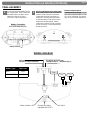
Lamp
Lamp
DC output to the remote units.
Yellow/Red stripe (+) Blue/Black stripe (-)
Input from branch circuit. See label on
wire pair for voltage requirement.
Status Indicator LED
Remote test Option
(standard with SDRT)
Test Switch
WIRING DIAGRAM
Battery Type Total Load
NiCd 2.4W
LiFePO4 (LTP) 4.8W

page 4
TESTING and MAINTENANCE
NOTE: Emergency lighting systems should be tested in
accordance with NFPA 101 or as often as local codes
require, to ascertain that all components are operational.
NOTE: Allow batteries to charge for 24 hours before initial
testing.
Manual testing:
If the batteries are sufficiently charged, either press and release
the “TEST” button or use the RTKIT (remote tester accessory,
up to 40’ away for SDRT units only) on the bottom of the unit to
activate a 60-second test, during which the lamps will turn on.
Triggering either option a second time will enable a 90-minute
tests indicated by 5 flashes of the lamps. Triggering either
option a third time will disable manual testing.
Self-Diagnostics (SDRT feature)
Units with this option automatically perform a 5-minute self-
diagnostic test of the charging electronics, battery, and lamps
every 30 days, and a 90-minute test every year, indicating
system status as shown in the table at right. First self test
occurs after 15 days of continuous AC Power.
Postponing a self-test:
If an automatic self-test occurs at a time when it is not desirable
for the unit lamps to be on, it can be postponed for 8 hours
either by pressing and releasing the “TEST” button or by using
RTKIT (remote tester accessory, up to 40’ away).
Cancelling emergency operation:
Press and hold the “TEST” button for several seconds or
activate using the RTKIT (remote tester accessory, up to 40’
away), during which the status indicator will flash until the lamps
turn off. This restores the AC Reset state in which the unit is
shipped.
Load-Learning feature:
Self-Diagnostic units automatically ‘learn’ their total connected
lamp load during the first scheduled self-test (~15 days). The
load-learning function can also be initiated manually by
pressing and holding the “TEST” button for 7 seconds (count
flashes), during this period the lamps will turn on. After 7
seconds, release the button, the lamps will turn off within 2
seconds indicating load learn complete. If lamps stay on longer,
load learn was not successful. This manual load-learning
feature should be initiated whenever the total connected lamp
load of the unit is changed, or a lamp is replaced.
NOTE: Manual load-learning functions cannot be initiated if
there is inadequate charge in the batteries. If this is so, wait
until the unit indicates full battery charge (solid green status
indication) before initiating the manual load-learning function.
Clearing a failure indication:
After a failure condition has been corrected and power is
restored to the unit, clear the failure indication either by
pressing the “TEST” button once or by using the RTKIT
(remote tester accessory, up to 40’ away).
IMPORTANT BATTERY INFORMATION:
Batteries are perishable items. For best results, it is
recommended that the batteries receive an initial charge within
the first six months of the manufacture date of the fixture. The
manufacture date can be found on the outside of the unit
packaging and on the product label as part of the Date Code /
Series. The first two digits in the date code represent the year
and the second two digits represent the month. In many cases,
batteries beyond the initial charge recommendation time frame
will recover if fully charged soon after installation. If such a
battery does not recover after a full initial charge, it should be
replaced.
“TEST” button
Unit Status Indications
The “TEST” button illuminates to indicate the following conditions:
Indication:
Status:
Off
Unit is off
Flashing green
Unit is in Emergency
operation or Test
Solid amber
Battery is charging
Solid green
Battery is fully charged
Flashing R / G
Manual test, battery not fully charged
(SDRT
only)
1x red flashing
Battery failure
(SDRT only)
2x red flashing
Lamp failure
(SDRT only)
3x red flashing
Charger / electronics failure
(SDRT only)
Flashing R/Amber
Unable to charge
Solid Red
Battery is disconnected
Remote Test (SDRT): (RTKIT sold separately)
Units with the self-diagnostics/remote test feature allows
manual test activation using a laser pointer. Aim the laser
beam straight onto the circular area labeled near the “TEST”
button for a few moments to activate a 60-second test. (See
also “Manual testing”) A test in progress may be cancelled by
aiming the beam at the test area again. NOTE: The remote
tester should not be used to initiate the Load Learning feature.
SDRT: aim laser pointer here

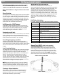
1
2 3
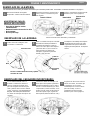
Disconnect battery from charger board.
Release battery strap.
BATTERY HANDLING WARNINGS:
• Dispose of used batteries promptly.
• Keep away from children.
• Do not disassemble.
• Do not dispose of in fire.
BATTERY REPLACEMENT
Unit features and battery details shown may vary. See also “Battery Connection”, page 3.
LAMP REPLACEMENT
page 5
TESTING and MAINTENANCE
With the unit oriented as in the below
view, flex the channel at the left end
of the charger board outward to
release and remove it. Unplug the
battery and other connections. See
“Lamp Replacement” above, to
disconnect the lamp wires from the
charger board.
CHARGER BOARD REPLACEMENT
Replace battery, secure the strap
snugly, and reconnect to the charger
board.
Re-assemble the unit (see also
step 5, page 3).
1
2
3
Remove lamp bezel as shown
below.
Gently bend the snap at each side of
the collar outward to release the lamp
assembly. Cut wires near lamp board
and strip back 1/4in. Connect stripped
wires to the replacement lamp,
following the yellow/blue polarity as
marked.
1
2
Make sure all wires are routed as
before, so as not to interfere with
proper assembly of the housing
onto the mounting plate. Re-
assemble the unit (see also step 5,
page 3).
NiCd Battery
Battery Strap
LiFePO4 Battery
Battery support
Release snaps
gently
Connector under
the PCB
Collar
collar button
Bezel
Carefully flex this edge free from collar button
Connect the lamp wires to the new
charger board, following the
yellow/blue polarity as marked.
Reconnect the battery and other
components (if included). For
insertion of PCB, insert right side of
PCB first, followed by left side
(click should be heard).
Replace the lamp assembly firmly
under the snaps on the collar, making
sure the lamp wires are not pinched.
Replace the bezel.
3
1
2
For Velcro strap: Release and reuse


ELM2L
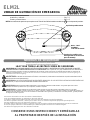
UNIDAD DE ILUMINACIÓN DE EMERGENCIA
Botón “TEST”
(PRUEBA)/
indicador de estado
Presione los pestillos para
desenganchar la carcasa de la
placa de montaje.
Opción de prueba remota
Instalación y cableado …………………..…………......…………………………………..Pág. 2-3
Prueba y mantenimiento ………...…………………………………………………………Pág. 4-5
MEDIDAS DE SEGURIDAD
IMPORTANTES
Cuando se utilizan aparatos eléctricos, deben tomarse
precauciones básicas de seguridad, incluidas las siguientes:
!
!
!
!
!
LEA Y SIGA TODAS LAS INSTRUCCIONES DE SEGURIDAD.
ADVERTENCIA: EL INCUMPLIMIENTO DE ESTAS INSTRUCCIONES Y ADVERTENCIAS PUEDE PROVOCAR LA MUERTE,
LESIONES GRAVES O DAÑOS IMPORTANTES A LA PROPIEDAD. Para su protección, lea y siga cuidadosamente estas advertencias e
instrucciones antes de instalar o realizar el mantenimiento de este equipo. Estas instrucciones no pretenden abarcar todas las situaciones de
instalación y mantenimiento. Si no comprende estas instrucciones o necesita información adicional, comuníquese con Lithonia Lighting o su
distribuidor local de Lithonia Lighting.
ADVERTENCIA: RIESGO DE DESCARGA ELÉCTRICA. NO CONECTE, DESCONECE NI REPARE EL EQUIPO MIENTRAS ESTE SE
ENCUENTRE EN FUNCIONAMIENTO.
ADVERTENCIA: NO UTILICE MATERIALES NI SOLVENTES ABRASIVOS. EL USO DE ESTAS SUSTANCIAS PUEDE DAÑAR LOS
APARATOS, LO QUE PUEDE OCASIONAR LESIONES PERSONALES.
ADVERTENCIA: RIESGO DE LESIONES PERSONALES: este producto puede tener bordes afilados. Use guantes para evitar cortes o
abrasiones al extraer el producto de la caja, manipularlo, instalarlo o repararlo.
ADVERTENCIA: La batería utilizada en este dispositivo puede presentar un riesgo de incendio o quemadura química si no se utiliza
correctamente. No desmontar, calentar a más de 70 °C (158 °F) o incinerar. Cambie la batería solo como se indica en la etiqueta de la batería y en
la página 5 de estas instrucciones. El uso de una batería no autorizada anula la garantía y la certificación UL de este producto, y puede presentar
un riesgo de incendio o explosión.
•Desconecte la fuente de CA antes de realizar el mantenimiento.
•Todo el mantenimiento debe ser realizado por personal calificado.
•Consulte su código local de edificación para conocer los tipos de cableado y instalación aprobados.
•No utilice el aparato al aire libre, a menos que se utilice con los accesorios Acuity Brands apropiados para la aplicación.
•No haga instalaciones cerca de calefactores eléctricos o a gas.
•El equipo debe ser montado en lugares y a alturas en las que no podrá ser fácilmente manipulado por personal no autorizado.
•El uso de equipos auxiliares no recomendados por el fabricante puede ocasionar una condición insegura.
•No utilice este equipo para otros usos distintos al indicado.
CONSERVE ESTAS INSTRUCCIONES Y ENTRÉGUELAS
AL PROPIETARIO DESPUÉS DE LA INSTALACIÓN
NOTA: Las versiones de producto que cumplen con el Título 20 de California están marcadas con “BC” en la etiqueta del producto.

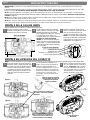
Dirija el conducto adecuado
para que todas las partes de
este lleguen al borde del
agujero troquelado
Luego de retirar el
troquelado
Use la arandela (Grainger # 4DAX6)
entre el accesorio del conducto y la
carcasa trasera si la conexión del
conducto interfiere con la batería.
Figura-3
página 2
INSTALACIÓN Y CABLEADO
1
2 3
En la placa de montaje, retire el orificio
troquelado central redondo y el par de orificios
troquelados de la caja de conexiones.
La ruta conduce a través de la abertura
central y utiliza los conectores con código
aprobado para realizar las conexiones.
(Vea el diagrama de cableado en la página
3). Organización de los cables y los
conectores dentro de la caja de conexiones.
Unidades con cables de lámparas
remotas: Si no se conectan las lámparas
remotas, los cables de estas lámparas (DC
de bajo voltaje + y -) deben quedar tapados
y colocados dentro de la placa de montaje
como se muestra.
Teniendo cuidado de no presionar los
cables o conductores organizados dentro
de la caja de unión, fije la placa de
montaje a los tornillos de la caja de unión.
NOTA: Para asegurar que los pestillos de
la placa de montaje estén correctamente
enganchados a la carcasa, NO AJUSTE
DEMASIADO LOS TORNILLOS.
En la parte superior del centro de la placa
de montaje, retire el orificio troquelado para
la conexión del conducto. También retire al
menos tres orificios troquelados. Conecte
el conducto y fije la placa de montaje a la
superficie de la pared con tornillos con una
calificación mínima de retiro de 30 libras
cada uno.
Vea el diagrama de cableado en la
página 3. Conecte las conexiones de
cable con código aprobado en la
fuente de alimentación de CA y en las
lámparas a distancia (si corresponde).
Organice los cables en las ranuras de
manera que los conectores estén
asegurados, como se muestra en las
figuras 2 o 3.
Retire el agujero troquelado en forma
de U de la parte superior central de la
carcasa. Sugerencia: Utilice primero
un par de cortacables para iniciar un
corte en la parte gruesa en cada lado
del troquelado y, a continuación,
termine de retirarlo con las pinzas.
MONTAJE DE LA CAJA DE UNIÓN
Algunos detalles que se muestran a continuación pueden variar.
MONTAJE EN SUPERFICIE DEL CONDUCTO
NOTA: Para evitar interferencia con los componentes de la carcasa, use los conectores más compactos apropiados para el calibre de los cables.
1
2 3
Cortar
Fije los conectores de cable cerca
del centro o cerca de los pestillos
superiores
Figura-2
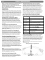
IMPORTANTE: Proporcione a cada unidad una fuente de CA no conmutada monofásica de un circuito utilizado para la iluminación
normal.
Las versiones del producto “UVOLT” funcionan con 120 voltios hasta 347 voltios. Todas las demás versiones funcionan con 120 voltios
hasta 277 voltios. EL PRODUCTO PUEDE DAÑARSE SI SE EXCEDE EL VOLTAJE DE ENTRADA.
NOTA: La batería debe estar conectada a la placa del cargador antes de aplicar la alimentación de CA a la unidad. La batería puede
dañarse si permanece conectada durante más de 24 horas sin alimentación de CA continua. Vea también “Información importante de
la batería”, página 4.
NOTA: Para cumplir con los requisitos mínimos de iluminación de la NFPA 101 (Código actual de Seguridad Humana), la máxima altura
de montaje de ELM2L desde el suelo es de 11.7 pies.
NOTA: No conecte la batería o la unidad de alimentación hasta que las unidades remotas (si corresponde) estén totalmente conectadas
y los cables estén aislados de otros potenciales (es decir, los cables remotos deben aislarse de la toma de tierra).
Placa de montaje:
7 in
4 3/8 in
3 1/4 in
Cajas de unión alojadas:
Cuadrada de 4 in
Octagonal de 4 in
Redonda u octagonal de 3 1/2 in
Caja de salida individual

página 3
INSTALACIÓN Y CABLEADO (CONTINUACIÓN)
4
5
Accesorios de la carcasa para la placa
de montaje:
Asegúrese de que todos los cables y los
conectores sigan una ruta para evitar la
interferencia con otros componentes. Alinee
las aberturas de los pestillos en el lado inferior
de la carcasa con los botones de los pestillos
en la placa de montaje. Presione firmemente
la carcasa directamente sobre la placa de
montaje, asegurándose de que los cuatro
pestillos estén completamente enganchados
y la carcasa esté estrechamente alineada con
la superficie de montaje.
MONTAJE FINAL
Conexión de la batería
Nota: Algunos detalles pueden variar.
Conecte el enchufe de la batería
polarizado a la placa del cargador.
Asegúrese de verificar el recorrido del
cable para evitar interferencias con el
conector de entrada de CA o con otros
componentes.
Requisitos de la Comisión Federal
de Comunicaciones (FCC):
Este dispositivo cumple con el Título
47 de la FCC, Parte 15, Subparte B.
Este dispositivo no causa
interferencia dañina.
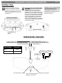
conector de la
batería
Batería
Lámpara
Lámpara
Lámpara remota cables de salida de CC.
Raya roja / Amarillo (+) Raya negra / azul (-)
Cables de entrada de CA. Consulte la etiqueta en el par
de alambres para conocer los requisitos de voltaje.
Led indicador de estado
Opción de prueba remota
(estándar con SDRT)
Interruptor de prueba
DIAGRAMA DEL CABLEADO
Tipo de batería Carga total
NiCd 2,4 W
LiFePO4 (LTP) 4,8 W

página 4
PRUEBA Y MANTENIMIENTO
NOTA: Los sistemas de iluminación de emergencia deben ser
probados de acuerdo con la norma NFPA 101 o con la
regularidad que exijan los códigos locales, para verificar que
todos los componentes sean operativos.
NOTA: Deje que las baterías se carguen por 24 horas antes
de la prueba inicial.
Prueba manual:
Si las baterías tienen carga suficiente, presione y suelte el botón
"TEST", o use RTKIT (accesorio de prueba remota, hasta 40 pies
de distancia solo para unidades SDRT) en la parte inferior de la
unidad para activar una prueba de 60 segundos durante la cual las
lámparas se encenderán. Activar cualquiera de las opciones por
segunda vez permitirá una prueba de 90 minutos indicada por 5
flashes de las lámparas. Activar cualquiera de las opciones por
tercera vez inhabilitará la prueba manual.
Autodiagnóstico (característica SDRT)
Las unidades con esta opción realizan automáticamente una
prueba de autodiagnóstico de 5 minutos en los dispositivos
electrónicos de carga, la batería y las lámparas cada 30 días, y
una prueba de 90 minutos al año, la cual indica el estado del
sistema como se muestra en la tabla de la derecha. La primera
autoevaluación se produce después de 15 días de alimentación de
CA continua.
Postergación de una autoevaluación:
Si una autoevaluación automática se produce en un momento en que
no es conveniente que las lámparas de la unidad estén encendidas,
se puede postergar la operación durante 8 horas al presionar o soltar
el botón “TEST”, o al usar la RTKIT (accesorio de prueba remota,
hasta 40 pies de distancia).
Operación de cancelación de emergencia:
Mantenga presionado el botón “TEST” por varios segundos o
active utilizando RTKIT (accesorio de prueba remota, hasta 40
pies de distancia), durante los cuales el indicador de estado será
intermitente hasta que las luces se apaguen. Esto restaura el
estado de restablecimiento CA en el que se envía la unidad.
Función de aprendizaje de carga:
Las unidades de autodiagnóstico “aprenden” automáticamente su
carga total de la lámpara conectada durante la primera
autoevaluación programada (aproximadamente 15 días). La función
de aprendizaje de carga también puede iniciarse manualmente al
mantener presionado el botón “TEST” por 7 segundos (contar las
intermitencias), durante los cuales las lámparas se encenderán.
Después de 7 segundos, suelte el botón; las lámparas se apagarán
en 2 segundos, lo que indica que se completó el aprendizaje de
carga. Si las lámparas permanecen encendidas durante más tiempo,
significa que el aprendizaje de carga no pudo completarse. Esta
característica de aprendizaje de carga manual debe iniciarse siempre
que la unidad de la lámpara conectada esté totalmente cargada o que
una lámpara sea reemplazada.
NOTA: Las funciones de aprendizaje de carga manuales no
pueden iniciarse si las baterías no tienen carga suficiente. Si esto
es así, espere hasta que la unidad indique que la batería ha sido
totalmente cargada (indicador de estado verde fijo) antes de iniciar
la función de aprendizaje de carga manual.
Aclaración de indicaciones de falla:
Después de corregir un error y luego de que se restablezca la
alimentación de la unidad, desactive la indicación de error al
presionar el botón “TEST” una vez o utilizando RTKIT (accesorio
de prueba remota, hasta 40 pies de distancia).
INFORMACIÓN IMPORTANTE SOBRE LAS BATERÍAS:
Las baterías son productos perecederos. Para obtener mejores
resultados, se recomienda que las baterías reciban una carga inicial
dentro de los primeros seis meses posteriores a la fecha de
fabricación del aparato. La fecha de fabricación se encuentra en el
exterior del empaque de la unidad y en la etiqueta del producto,
como lo establece el código de fecha/número de serie. Los dos
primeros dígitos del código de fecha representan el año y los
segundos dos dígitos representan el mes. En muchos casos, las
baterías, más allá del marco de tiempo recomendado para la carga
inicial, se recuperarán completamente si son cargadas después de
la instalación. Si este tipo de baterías no se recupera después de
una carga inicial completa, estas deben ser reemplazadas.
Botón “TEST”
Indicaciones sobre el estado de la unidad
El botón "TEST” se ilumina para indicar las siguientes condiciones:
Indicación:
Estado:
Apagado
La unidad está apagada.
Luz verde
intermitente
La unidad está en modo de Emergencia
o
Prueba
.
Luz ámbar fija
La batería se
está cargando.
Luz verde fija
La batería está
totalmente cargada.
Rojo/verde
intermitente
Prueba manual, la batería no está
completamente cargada
(solo SDRT).
1 intermitencia de
luz roja
Falla en la batería
(solo SDRT).
2 intermitencias de
luz roja
Falla en la lámpara
(solo SDRT).
3 intermitencias de
luz roja
Falla en el cargador o los dispositivos
electrónicos
(solo SDRT).
Luz roja/ámbar
intermitente
No se
puede cargar.
Luz roja fija
La batería está desconectada.
Prueba remota (SDRT): (RTKIT se vende por separado)
Las unidades con autodiagnóstico / función de prueba remota
permiten la activación manual de la prueba usando un puntero láser.
Dirija el puntero láser directamente sobre el área circular etiquetada
cerca del botón “TEST” durante unos instantes para activar una
prueba de 60 segundos. (Vea también “Prueba manual”). Si desea
cancelar una prueba en curso, dirija nuevamente el puntero láser
sobre el área de prueba.
NOTA: probador remoto no debe usarse para iniciar la función de
aprendizaje de carga.
SDRT: apunte aquí con el puntero láser

1
2 3
Desconecte la batería del cargador
incorporado. Suelte la cinta de la batería.
ADVERTENCIAS PARA EL
MANEJO DE LA BATERÍA:
• Desechar las baterías usadas
inmediatamente.
• Mantener fuera del alcance de los niños.
• No desmontar.
• No arrojar al fuego.
REEMPLAZO DE LA BATERÍA:
Las características de la unidad y los detalles de la batería que se muestran pueden variar. Vea también “Conexiones de batería” en la página 3.
REEMPLAZO DE LA LÁMPARA:
página 5
PRUEBA Y MANTENIMIENTO
Con la unidad orientada como se
muestra a continuación, flexione el
canal en el extremo izquierdo de la
placa del cargador hacia afuera para
soltar y retirarlo. Desconecte la batería
y otras conexiones. Vea “Reemplazo de
lámpara” más arriba para desconectar
los cables de la lámpara de la placa del
cargador.
REEMPLAZO DEL CARGADOR INCORPORADO:
Reemplace la batería, asegure bien la
cinta y vuelva a conectarla a la placa
del cargador.
Vuelva a ensamblar la unidad (consulte
también el paso 5 en la página 3).
1
2
3
Retire el bisel de la lámpara como
se muestra a continuación.
Doble con cuidado el encaje en cada lado
del cuello hacia afuera para liberar el
ensamblaje de la lámpara. Corta los
cables cerca de la placa de la lámpara
y tira hacia atrás 1 / 4in. Conecte los
cables pelados a la lámpara de
reemplazo, siguiendo la polaridad
amarilla / azul marcada.
1
2
Asegúrese de direccionar todos los
cables como antes, de manera que
no interfieran con el correcto
ensamblaje de la carcasa sobre la
placa de montaje. Vuelva a
ensamblar la unidad (consulte
también el paso 5 en la página 3).
Batería NiCd
Cinta de la
batería
Batería LiFePO4
Soporte de la
batería
Suelte los
encajes con
cuidado
Conector debajo
del PCB
Cuello
botón del cuello
Bisel
Flexione cuidadosamente este borde y apártelo
del botón del cuello
Conecte los cables de la lámpara a la
nueva placa del cargador, siguiendo la
polaridad amarillo/azul como se indica.
Vuelva a conectar la batería y los otros
componentes (si están incluidos). Para
insertar el PCB, inserte el lado derecho
del PCB en primer lugar, seguido del
lado izquierdo (debe escuchar un “clic”).
Reemplace el ensamblaje de la lámpara
firmemente bajo el encaje en el cuello,
asegurándose de que los cables de la
lámpara presenten pellizcos. Reemplace
el bisel.
3
1
2
Para la correa de velcro: liberación y reutilización

N.º de pieza: 912-00026-002
Rev. D, 5/2019
© Acuity Brands Lighting, Inc. 2019
Todos los derechos reservados.
SOLUCIONES DE SEGURIDAD PERSONAL
TELÉFONO: 800-705-SERV (7378) www.lithonia.com
Este documento ha sido traducido del inglés por razones de conveniencia. En el caso de hubiera alguna
inconsistencia entre el texto del documento en inglés y esta traducción, prevalecerá el texto en inglés.
Todas las marcas registradas a las que se hace referencia son propiedad de sus respectivos dueños. Las marcas
registradas de Acuity Brands Lighting que están marcadas con el símbolo ® están registradas en los EE. UU. y
pueden estar registradas en otros países.
-
 1
1
-
 2
2
-
 3
3
-
 4
4
-
 5
5
-
 6
6
-
 7
7
-
 8
8
-
 9
9
-
 10
10
-
 11
11
-
 12
12


Lithonia Lighting ELB B001 R6 Guía de instalación
- Tipo
- Guía de instalación
- Este manual también es adecuado para
en otros idiomas
Artículos relacionados
-
Acuity Brands ELM2LF Emergency Light Instrucciones de operación
-
Lithonia Lighting EXR LED EL M6 Guía de instalación
-
Lithonia Lighting JCBL 24000LM MVOLT GZ10 50K 70CRI PM Instrucciones de operación
-
-
-
Lithonia Lighting LTIHSQLED27K90CRIMW Guía de instalación
-
Lithonia Lighting OMS 1000 120 DDB M6 Guía de instalación
-
Lithonia Lighting LTKMSBK MR16GU10 3L BN Manual de usuario
-
