Dell N20XX Manual de usuario
- Categoría
- Conmutadores de red
- Tipo
- Manual de usuario
Este manual también es adecuado para

Dell N20xx/N30xx
Series Switch
Getting Started Guide
Guide de mise en route
Handbuch zum Einstieg
Руководство по началу работы
Guía de introducción
Başlangıç Kılavuzu
הדובע תליחת ךירדמ
Regulatory Models: N2024, N2024P,
N2048, N2048P, N3024, N3024P, N3048,
N3048P, N3024F


Dell N20xx/N30xx
Series Switch
Getting Started Guide
Regulatory Models: N2024, N2024P,
N2048, N2048P, N3024, N3024P, N3048,
N3048P, N3024F

Notes, Cautions, and Warnings
NOTE: A NOTE indicates important information that helps you make better use of
your switch.
CAUTION: A CAUTION indicates either potential damage to hardware or loss of
data and tells you how to avoid the problem.
WARNING: A WARNING indicates a potential for property damage, personal
injury, or death.
____________________
© 2013 Dell Inc.
Trademarks used in this text: Dell
®
, the DELL logo, OpenManage™, and ReadyRails™ are
trademarks of Dell Inc. Microsoft
®
, and Windows
®
are registered trademarks of Microsoft Corporation
in the United States and/or other countries.
Regulatory Models N2024, N2024P, N2048, N2048P, N3024, N3024P, N3048, N3048P, N3024F
December 2013 P/N F5CWH Rev. A00

Contents 3
Contents
1 Introduction . . . . . . . . . . . . . . . . . . . . . . . . 7
2 N20xx Series Overview
. . . . . . . . . . . . . . . 7
3 N20xx Series Hardware Overview
. . . . . . . 8
N20xx Series Front Panel . . . . . . . . . . . . . . . . . 8
Switch Ports
. . . . . . . . . . . . . . . . . . . . 10
Console Port
. . . . . . . . . . . . . . . . . . . . 10
USB Port
. . . . . . . . . . . . . . . . . . . . . . 11
Reset Button
. . . . . . . . . . . . . . . . . . . . 11
Port and System LEDs
. . . . . . . . . . . . . . . 11
Stack Master LED and Stack Number Display
. . . 11
N20xx Series Back Panel
. . . . . . . . . . . . . . . . 12
Power Supplies
. . . . . . . . . . . . . . . . . . . 12
Ventilation System
. . . . . . . . . . . . . . . . . 13
N20xx Model Summary
. . . . . . . . . . . . . . . . . 13
4 N20xx Series Installation . . . . . . . . . . . . 14
Site Preparation . . . . . . . . . . . . . . . . . . . . . 14
Unpacking the N20xx Switch
. . . . . . . . . . . . . . 15
Package Contents
. . . . . . . . . . . . . . . . . 15
Unpacking Steps
. . . . . . . . . . . . . . . . . . 15

4 Contents
Rack Mounting a N20xx Switch . . . . . . . . . . . . . 15
Installing in a Rack
. . . . . . . . . . . . . . . . . 15
Installing as a Free-standing Switch
. . . . . . . . 17
Stacking Multiple N20xx Switches
. . . . . . . . . . . 17
Creating a Switch Stack
. . . . . . . . . . . . . . 17
5 Starting and Configuring the N20xx Switch 20
Connecting a N20xx Switch to a Terminal . . . . . . . 21
Connecting a N20xx Switch to a Power Source
. . . . 22
AC and DC Power Connection
. . . . . . . . . . . 22
Booting the N20xx Switch
. . . . . . . . . . . . . . . . 23
Performing the N20xx Initial Configuration
. . . . . . . 24
Enabling Remote Management
. . . . . . . . . . . 24
Initial Configuration Procedure
. . . . . . . . . . . 25
Example Session
. . . . . . . . . . . . . . . . . . 26
Dell Easy Setup Wizard Console Example
. . . . . 27
Next Steps
. . . . . . . . . . . . . . . . . . . . . 30
6 N30xx Series Overview . . . . . . . . . . . . . 31
7 N30xx Series Hardware Overview
. . . . . 31
N30xx Series Front Panel . . . . . . . . . . . . . . . . 32
Switch Ports
. . . . . . . . . . . . . . . . . . . . 34
Console Port
. . . . . . . . . . . . . . . . . . . . 34
Out-of-Band Management Port
. . . . . . . . . . . 35
USB Port
. . . . . . . . . . . . . . . . . . . . . . 35
Reset Button
. . . . . . . . . . . . . . . . . . . . 35

Contents 5
Port and System LEDs . . . . . . . . . . . . . . . 35
Stack Master LED and Stack Number Display
. . . 36
N30xx Series Back Panel
. . . . . . . . . . . . . . . . 36
Expansion Slots for Plug-in Modules
. . . . . . . . 37
Power Supplies
. . . . . . . . . . . . . . . . . . . 38
Ventilation System
. . . . . . . . . . . . . . . . . 38
N30xx Model Summary
. . . . . . . . . . . . . . . . . 39
8 N30xx Series Installation . . . . . . . . . . . . 40
Site Preparation . . . . . . . . . . . . . . . . . . . . . 40
Unpacking the N30xx Switch
. . . . . . . . . . . . . . 41
Package Contents
. . . . . . . . . . . . . . . . . 41
Unpacking Steps
. . . . . . . . . . . . . . . . . . 41
Rack Mounting a N30xx Switch
. . . . . . . . . . . . . 42
Rack Mounting Safety Considerations
. . . . . . . 42
Installing the Dell ReadyRail System
. . . . . . . . 43
Installing as a Free-standing Switch
. . . . . . . . 47
Stacking Multiple N30xx Switches
. . . . . . . . . . . 47
Creating a Switch Stack
. . . . . . . . . . . . . . 47
9 Starting and Configuring the N30xx Switch 49
Connecting a N30xx Switch to a Terminal . . . . . . . 50
Connecting a N30xx Switch to a Power Source
. . . . 51
AC and DC Power Connection
. . . . . . . . . . . 51
Booting the N30xx Switch
. . . . . . . . . . . . . . . . 52
Performing the N30xx Initial Configuration . . . . . . . 53


Getting Started Guide 7
Introduction
This document provides basic information about the Dell N20xx/N30xx
Series switches, including how to install a switch and perform the initial
configuration. For information about how to configure and monitor switch
features, see the User’s Configuration Guide, which is available on the Dell
Support website at dell.com/support/manuals, for the latest updates on
documentation and firmware.
This document contains the following sections:
• N20xx Series Overview
• N20xx Series Hardware Overview
• N20xx Series Installation
• Starting and Configuring the N20xx Switch
• N30xx Series Overview
• N30xx Series Hardware Overview
• N30xx Series Installation
• Starting and Configuring the N30xx Switch
NOTE: Switch administrators are strongly advised to maintain Dell Networking
switches on the latest version of the Dell Networking Operating System (DNOS).
Dell Networking continually improves the features and functions of DNOS based on
feedback from you, the customer. For critical infrastructure, prestaging of the new
release into a noncritical portion of the network is recommended to verify network
configuration and operation with the new DNOS version.
N20xx Series Overview
The Dell N20xx switches are stackable Layer 2 Gigabit Ethernet switches and
include the following models:
• Dell N2024
• Dell N2024P
• Dell N2048
• Dell N2048P

8 Getting Started Guide
N20xx Series Hardware Overview
This section contains information about device characteristics and modular
hardware configurations for the N20xx Series switches.
All N20xx non-PoE models are 1U, rack-mountable switches with the
following physical dimensions:
• 440.0 x 257.0 x 43.5 mm (W x D x H).
• 17.3 x 10.1 x 1.7 inches (W x D x H).
All N20xx PoE models are 1U, rack-mountable switches with the following
physical dimensions:
• 440.0 x 387.0 x 43.5 mm (W x D x H).
• 17.3 x 15.2 x 1.7 inches (W x D x H).
N20xx Series Front Panel
The following images show the front panels of the switch models in the
N20xx Series.
Figure 1-1. N2048 Series with 48 10/100/1000BASE-T Ports (Front Panel)
In addition to the switch ports, the front panel of each model in the N20xx
series includes the following ports:
• Console port
• USB port
48 10/100/1000BASE-T Ports
SFP+
Ports
Console Port
USB Port

Getting Started Guide 9
Figure 1-2. N2024 Close-up
The N20xx front panel, shown in Figure 1-2, has status LEDs for over-
temperature alarm, internal power, and status on the top row. The bottom
row of status LEDs displays stack master, redundant power supply (RPS)
status and fan alarm status.
Figure 1-3. N2024P Close-up
The N20xxP front panel, shown in Figure 1-3, has status LEDs for over-
temperature alarm, internal power and status on the top row. The bottom row
of status LEDs displays stack master, modular power supply (MPS) status and
fan alarm status.

10 Getting Started Guide
Switch Ports
The N2024/N2024P front panel provides 24 Gigabit Ethernet
(10/100/1000BASE-T) RJ-45 ports that support auto-negotiation for speed,
flow control, and duplex. The N2024/N2024P models support two SFP+ 10G
ports. Dell-qualified SFP+ transceivers are sold separately.
The N2048/N2048P front panel provides 48 Gigabit Ethernet (10BASE-T,
100BASE-TX, 1000BASE-T) RJ-45 ports that support auto-negotiation for
speed, flow control, and duplex. The N2048/N2048P support two SFP+ 10G
ports. Dell-qualified SFP+ transceivers are sold separately.
The front-panel switch ports have the following characteristics:
• The switch automatically detects the difference between crossed and
straight-through cables on RJ-45 ports and automatically chooses the MDI
or MDIX configuration to match the other end.
• SFP ports support Dell-qualified transceivers.
• RJ-45 ports support full-duplex mode 10/100/1000 Mbps speeds on
standard Category 5 UTP cable.
• SFP+ ports support SFP+ transceivers and SFP+ copper twin-ax
technology plus SFP transceivers operating at 1G.
• The N2024P/N2048P front panel ports support PoE (15.4W) and PoE+
(30W).
Console Port
The console port provides serial communication capabilities, which allows
communication using RS-232 protocol. The serial port provides a direct
connection to the switch and allows access to the CLI from a console
terminal connected to the port through the provided serial cable (with RJ45
YOST to female DB-9 connectors).
The console port is separately configurable and can be run as an asynchronous
link from 1200 baud to 115,200 baud.
The Dell CLI only supports changing the speed. The defaults are 9600 baud
rate, 8 data bits, No Parity, 1 Stop Bit, No Flow Control.

Getting Started Guide 11
USB Port
The Type-A, female USB port supports a USB 2.0-compliant flash memory
drive. The Dell Networking switch can read or write to a flash drive formatted
as FAT-32. You can use a USB flash drive to copy switch configuration files
and images between the USB flash drive and the switch. You can also use the
USB flash drive to move and copy configuration files and images from one
switch to other switches in the network.
The USB port does not support any other type of USB device.
Reset Button
The reset button is accessed through the pinhole and allows you to perform a
hard reset on the switch. To use the reset button, insert an unbent paper clip
or similar tool into the pinhole. When the switch completes the boot process
after the reset, it resumes operation with the most recently saved
configuration. Any changes made to the running configuration that were not
saved to the startup configuration prior to the reset are lost.
Port and System LEDs
The front panel contains light emitting diodes (LEDs) that indicate the
status of port links, power supplies, fans, stacking, and the overall system
status.
For information about the status that the LEDs indicate, see the User’s
Configuration Guide.
Stack Master LED and Stack Number Display
When a switch within a stack is the master unit, the stack master LED, which
is labeled M, is solid green. If the M LED is off, the stack member is not the
master unit. The Stack No. panel displays the unit number for the stack
member. If a switch is not part of a stack (in other words, it is a stack of one
switch), the M LED is illuminated, and the unit number is displayed.

12 Getting Started Guide
N20xx Series Back Panel
The following images show the back panels of the N20xx switches.
Figure 1-4. N20xx Back Panel
Figure 1-5. N2024P/N2048P Back Panel
The term mini-SAS refers to the stacking port cable connections shown in
Figure 1-6. See Stacking Multiple N20xx Switches for information on using
the mini-SAS ports to connect switches.
Figure 1-6. N2048 Mini-SAS Stacking Ports and Fans
Power Supplies
N2024 and N2048
N2024 and N2048 switches have an internal 100-watt power supply. The
additional redundant power supply (Dell Networking RPS720) provides 180
watts of power and gives full redundancy for the switch.
Fan Vents
AC Power Receptacle
Mini-SAS stacking ports

Getting Started Guide 13
N2024P and N2048P
Dell Networking N2024P and N2048P switches have an internal 1000-watt
power supply feeding up to 24 PoE devices at full PoE+ power (850W). An
additional external power supply (MPS1000) provides 1000 watts and gives
full power coverage for all 48 PoE devices (1800W).
NOTE: PoE power is dynamically allocated. Not all ports will require the full PoE+
power.
CAUTION: Remove the power cable from the power supplies prior to removing
the power supply module itself. Power must not be connected prior to insertion in
the chassis.
Ventilation System
Two fans cool the N20xx switches.
N20xx Model Summary
Table 1-1. N20xx Model Summary
Marketing
Model
Name
Description Power
Supply
Unit
Regulatory
Model Number
Regulatory
Typ e
Number
N2024 24x1G/2x10G SFP+/2x
Stacking
100W E04W E04W001
N2024P 24x1G/2x10G SFP+/2x
Stacking/24x PoE+ Ports
1000W E05W E05W001
N2048 48x1G/2x10G SFP+/2x
Stacking
100W E04W E04W002
N2048P 48x1G/2x10G SFP+/2x
Stacking/48x PoE+ Ports
1000W E05W E05W002

14 Getting Started Guide
N20xx Series Installation
Site Preparation
N20xx Series switches can be mounted in a standard 48.26 cm (19-inch) rack
or placed on a flat surface.
Make sure that the chosen installation location meets the following site
requirements:
•
Power
— The switch is installed near an easily accessible 100–240 VAC,
50–60 Hz outlet.
•
Clearance
— There is adequate front and rear clearance for operator
access. Allow clearance for cabling, power connections, and ventilation.
•
Cabling
— The cabling is routed to avoid sources of electrical noise such
as radio transmitters, broadcast amplifiers, power lines, and fluorescent
lighting fixtures.
•
Ambient Temperature
— The ambient switch operating temperature
range is 0 to 45ºC (32 to 113ºF) at a relative humidity of up to 95 percent,
non-condensing.
NOTE: Decrease the maximum temperature by 1°C (1.8°F) per 300 m (985 ft.) above
900m (2955 ft.).
•
Relative Humidity
— The operating relative humidity is 8% to 85%
(noncondensing) with a maximum humidity gradation of 10% per hour.

Getting Started Guide 15
Unpacking the N20xx Switch
Package Contents
When unpacking each switch, make sure that the following items are
included:
• One Dell Networking switch
• One RJ-45 to DB-9 female cable
• One rack-mount kit (N20xx) for rack installation, two mounting brackets,
bolts, and cage nuts
• One set of self-adhesive rubber pads for the free-standing switch (four pads
are included)
Unpacking Steps
NOTE: Before unpacking the switch, inspect the container and immediately report
any evidence of damage.
1
Place the container on a clean, flat surface and cut all straps securing the
container.
2
Open the container or remove the container top.
3
Carefully remove the switch from the container and place it on a secure
and clean surface.
4
Remove all packing material.
5
Inspect the product and accessories for damage.
Rack Mounting a N20xx Switch
WARNING: Read the safety information in the Safety and Regulatory Information
as well as the safety information for other switches that connect to or support the
switch.
The AC power connector is on the back panel of the switch.
Installing in a Rack
WARNING: Do not use rack mounting kits to suspend the switch from under a
table or desk, or attach it to a wall.

16 Getting Started Guide
CAUTION: Disconnect all cables from the switch before continuing. Remove all
self-adhesive pads from the underside of the switch, if they have been attached.
CAUTION: When mounting multiple switches into a rack, mount the switches
from the bottom up.
1
Place the supplied rack-mounting bracket on one side of the switch,
ensuring that the mounting holes on the switch line up to the mounting
holes in the rack-mounting bracket. Figure 1-7 illustrates where to mount
the brackets.
Figure 1-7. Attaching the Brackets
2
Insert the supplied bolts into the rack-mounting holes and tighten with a
screwdriver.
3
Repeat the process for the rack-mounting bracket on the other side of the
switch.
4
Insert the switch into the 48.26 cm (19 inch) rack, ensuring that the rack-
mounting holes on the switch line up to the mounting holes in the rack.
5
Secure the switch to the rack with either the rack bolts or cage nuts and
cage-nut bolts with washers (depending on the kind of rack you have).
Fasten the bolts on bottom before fastening the bolts on top.
CAUTION: Make sure that the supplied rack bolts fit the pre-threaded holes in the
rack.
NOTE: Make sure that the ventilation holes are not obstructed.

Getting Started Guide 17
Installing as a Free-standing Switch
NOTE: We strongly recommend mounting the switch in a rack.
Install the switch on a flat surface if you are not installing it in a rack. The
surface must be able to support the weight of the switch and the switch
cables. The switch is supplied with four self-adhesive rubber pads.
1
Attach the self-adhesive rubber pads on each location marked on the
bottom of the switch.
2
Set the switch on a flat surface, and make sure that it has proper
ventilation by leaving 5 cm (2 inches) on each side and 13 cm (5 inches) at
the back.
Stacking Multiple N20xx Switches
You can stack N20xx switches up to 12 switches high using the mini-SAS
ports located on the rear of the switch. N20xx switches support stacking only
with other N20xx series switches. When multiple switches are connected
together through the stack ports, they operate as a single unit with up to 576
front panel ports. The stack operates and is managed as a single entity.
NOTE: If you are installing a stack of switches, you need to assemble and cable the
stack before powering up and configuring it. When a stack is powered up for the
first time, the switches elect a Master Switch, which may occupy any location in
the stack. The Master LED on the front panel is illuminated on the master unit.
Creating a Switch Stack
Create a stack by connecting adjacent units using the mini-SAS stacking
ports on the back panel of the switch. Figure 1-8 on page 18 shows the
switches connected in a ring topology, which is the recommended topology
for a stack.
1
Connect one of the mini-SAS cables into either of the stacking ports of the
top switch and the switch directly below it.
If necessary, use a separately purchased, longer (1 meter or 3 meter) mini-
SAS cable to connect the switches.
2
Repeat this process until all of the devices are connected.
3
Use the remaining stacking cable to connect the two remaining stacking
ports together so that a ring topology is assembled.

18 Getting Started Guide
Figure 1-8. Connecting a Stack of Switches
The stack in Figure 1-8 is connected in a ring topology and has the following
physical connections between the switches:
• The bottom mini-SAS port on Unit 1 is connected to the top mini-SAS
port on Unit 2.
• The bottom mini-SAS port on Unit 2 is connected to the top mini-SAS
port on Unit 3.
• The bottom mini-SAS port on Unit 3 is connected to the top mini-SAS
port on Unit 1.
Unit 1
Unit 2
Unit 3

Getting Started Guide 19
Stacking Standby
The stacking feature supports a Standby or backup unit that assumes the
Master unit role if the Master unit in the stack fails. As soon as a Master
failure is detected in the stack, the Standby unit initializes the control plane
and enables all other stack units with the current configuration. The Standby
unit maintains a synchronized copy of the running configuration for the
stack. The Standby unit is automatically selected in the stack; however, you
can use the CLI to select a different stack member as Standby. See the User’s
Configuration Guide or the CLI Reference Guide for more information.

20 Getting Started Guide
Starting and Configuring the N20xx
Switch
The following flow chart provides an overview of the steps you use to perform
the initial configuration after the switch is unpacked and mounted.
Figure 1-9. Installation and Configuration Flow Chart

Getting Started Guide 21
Connecting a N20xx Switch to a Terminal
After completing all external connections, connect a terminal to a switch to
configure the switch.
NOTE: Read the Release Notes for this product before proceeding. You can
download the Release Notes from the Dell Support website at
dell.com/support/manuals.
NOTE: We recommend that you obtain the most recent version of the user
documentation from the Dell Support website at dell.com/support/manuals.
To monitor and configure the switch via serial console, use the console port
on the front panel of the switch (see Figure 1-1 on page 8) to connect it to a
VT100 terminal or to a computer running VT100 terminal emulation
software. The console port is implemented as a data terminal equipment
(DTE) connector.
The following equipment is required to use the console port:
• VT100-compatible terminal or a computer with a serial port running
VT100 terminal emulation software,
such as Microsoft HyperTerminal.
• A serial cable (provided) with an RJ-45 connector for the console port and
DB-9 connector for the terminal.
Perform the following tasks to connect a terminal to the switch console port:
1
Connect the DB-9 connector on the serial cable to the terminal or
computer running VT100 terminal emulation software.
2
Configure the terminal emulation software as follows:
a
Select the appropriate serial port (for example, COM 1) to connect to
the console.
b
Set the data rate to 9600 baud.
c
Set the data format to 8 data bits, 1 stop bit, and no parity.
d
Set the flow control to none.
e
Set the terminal emulation mode to
VT100
.
f
Select Terminal keys for Function, Arrow, and Ctrl keys. Make sure
that the setting is for Terminal keys (not Microsoft Windows keys).

22 Getting Started Guide
3
Connect the RJ-45 connector on the cable directly to the switch console
port. The Dell Networking console port is located on the right side of the
front panel and is labeled with a
|O|O|
symbol, as shown in Figure 1-10
on page 22.
NOTE: Serial console access to the stack manager is available from any
serial port via the local CLI. Only one serial console session at a time is
supported.
Figure 1-10. N2024P Front Panel with Console Port
Connecting a N20xx Switch to a Power Source
CAUTION: Read the safety information in the Safety and Regulatory Information
manual as well as the safety information for other switches that connect to or
support the switch.
All N20xx models have one internal power supply. The
power receptacles are
on the back panel.
AC and DC Power Connection
1
Make sure that the switch console port is connected to a VT100 terminal
or VT100 terminal emulator via the RJ-45 to DB-9 female cable.
2
Using a 5-foot (1.5 m) standard power cable with safety ground connected,
connect the power cable to the AC main receptacle located on the back
panel (see Figure 1-11 on page 23).
3
Connect the power cable to a grounded AC outlet.
Console Port

Getting Started Guide 23
4
If you are using a redundant or external DC power supply, such as the Dell
Networking RPS720 or Dell Networking MPS1000, connect the DC power
cable to the DC receptacle located on the back panel. In Figure 1-11 on
page 23, the redundant power supply feed is in the middle and is labeled
RPS.
Figure 1-11. AC and DC Power Connection to an N2048 Switch
Booting the N20xx Switch
When the power is turned on with the local terminal already connected, the
switch goes through a power-on self-test (POST). POST runs every time the
switch is initialized and checks hardware components to determine if the
switch is fully operational before completely booting. If POST detects a
critical problem, the program flow stops. If POST passes successfully, valid
firmware is loaded into RAM. POST messages are displayed on the terminal
and indicate test success or failure. The boot process runs for approximately
60 seconds.
You can invoke the Boot menu after the first part of the POST is completed.
From the Boot menu, you can perform configuration tasks such as resetting
the system to factory defaults, activating the backup image, or recovering a
password. For more information about the Boot menu functions, see the CLI
Reference Guide.
To DC Power Source (Optional)
To AC Power Source

24 Getting Started Guide
Performing the N20xx Initial Configuration
The initial configuration procedure is based on the following assumptions:
• The Dell Networking switch was never configured before.
• The Dell Networking switch booted successfully.
• The console connection was established, and the
Dell Easy Setup Wizard
prompt appears on the screen of a VT100 terminal or terminal equivalent.
The initial switch configuration is performed through the console port. After
the initial configuration, you can manage the switch from the already-
connected console port or remotely through an interface defined during the
initial configuration.
NOTE: The switch is not configured with a default user name, password, or IP
address.
Before setting up the initial configuration of the switch, obtain the following
information from your network administrator:
• The IP address to be assigned to the management interface.
• The IP subnet mask for the network.
• The IP address of the management interface default gateway.
These settings are necessary to allow the remote management of the switch
through Telnet (Telnet client) or HTTP (Web browser).
Enabling Remote Management
On the N20xx switches, you can use any of the switch ports on the front panel
for in-band management. By default, all in-band ports are members of VLAN
1.
The Dell Easy Setup Wizard includes prompts to configure network
information for the VLAN 1 interface on the N20xx switch. You can assign a
static IP address and subnet mask or enable DHCP and allow a network
DHCP server to assign the information.
See the CLI Reference Guide for information about the CLI commands you
use to configure network information.

Getting Started Guide 25
Initial Configuration Procedure
You can perform the initial configuration by using the Dell Easy Setup
Wizard or by using the CLI. The wizard automatically starts when the switch
configuration file is empty. You can exit the wizard at any point by entering
[ctrl+z], but all configuration settings specified will be discarded, and the
switch will use the default values.
NOTE: If you do not run the Dell Easy Setup Wizard or do not respond to the initial
Easy Setup Wizard prompt within 60 seconds, the switch enters CLI mode. You must
reset the switch with an empty startup configuration in order to rerun the Dell Easy
Setup Wizard.
For more information about performing the initial configuration by using the
CLI, see the CLI Reference Guide. This Getting Started Guide shows how to
use the Dell Easy Setup Wizard for initial switch configuration. The wizard
sets up the following configuration on the switch:
• Establishes the initial privileged user account with a valid password. The
wizard configures one privileged user account during the setup.
• Enables CLI login and HTTP access to use the local authentication setting
only.
• Sets up the IP address for the VLAN 1 routing interface, of which all
in-band ports are members.
• Sets up the SNMP community string to be used by the SNMP manager at
a given IP address. You may choose to skip this step if SNMP management
is not used for this switch.
• Allows you to specify the network management system IP address or
permit management access from all IP addresses.
• Configures the default gateway IP address for the VLAN 1 interface.

26 Getting Started Guide
Example Session
This section describes a Dell Easy Setup Wizard session. The following
values are used by the example session:
• The SNMP community string to be used is
public
.
• The network management system (NMS) IP address is
10.1.2.100
.
• The user name is
admin
, and the password is
admin123
.
• The IP address for the VLAN 1 routing interface is
10.1.1.200
with a
subnet mask of
255.255.255.0
.
• The default gateway is
10.1.1.1
The setup wizard configures the initial values as defined above. After
completing the wizard, the switch is configured as follows:
• SNMPv2 is enabled and the community string is set up as defined above.
SNMPv3 is disabled by default.
• The admin user account is set up as defined.
• A network management system is configured. From the management
station, you can access the SNMP, HTTP, and CLI interfaces. You may also
choose to allow all IP addresses to access these management interfaces by
choosing the (0.0.0.0) IP address.
• An IP address is configured for the VLAN 1 routing interface.
• A default gateway address is configured.
NOTE: In the example below, the possible user options or default values are
enclosed in [ ]. If you press <Enter> with no options defined, the default value is
accepted. Help text is in parentheses.

Getting Started Guide 27
Dell Easy Setup Wizard Console Example
The following example contains the sequence of prompts and responses
associated with running an example Dell Easy Setup Wizard session, using
the input values listed above.
After the switch completes the POST and is booted, the following dialog
appears:
Unit 1 - Waiting to select management unit)>
Applying Global configuration, please wait...
Welcome to Dell Easy Setup Wizard
The Setup Wizard guides you through the initial switch
configuration, and gets you up and running as quickly
as possible. You can skip the setup wizard, and enter
CLI mode to manually configure the switch. You must
respond to the next question to run the setup wizard
within 60 seconds, otherwise the system will continue
with normal operation using the default system
configuration. Note: You can exit the setup wizard at
any point by entering [ctrl+z].
Would you like to run the setup wizard (you must
answer this question within 60 seconds)? [Y/N] y
Step 1:
The system is not set up for SNMP management by
default. To manage the switch using SNMP (required for
Dell Network Manager) you can
. Set up the initial SNMP version 2 account now.
. Return later and set up other SNMP accounts. (For
more information on setting up an SNMP version 1 or
3 account, see the user documentation).
Would you like to set up the SNMP management interface
now? [Y/N] y
To set up the SNMP management account you must specify
the management system IP address and the “community
string” or password that the particular management
system uses to access the switch. The wizard

28 Getting Started Guide
automatically assigns the highest access level
[Privilege Level 15] to this account. You can use Dell
Network Manager or other management interfaces to
change this setting, and to add additional management
system information later. For more information on
adding management systems, see the user documentation.
To add a management station:
Please enter the SNMP community string to be used.
[public]: public
NOTE: If it is configured, the default access level is set to the highest available
access for the SNMP management interface. Initially only SNMPv2 will be
activated. SNMPv3 is disabled until you return to configure security access for
SNMPv3 (e.g. engine ID, view, etc.).
Please enter the IP address of the Management System
(A.B.C.D) or wildcard (0.0.0.0) to manage from any
Management Station. [0.0.0.0]: 10.1.2.100
Step 2:
Now we need to set up your initial privilege (Level
15) user account. This account is used to login to the
CLI and Web interface. You may set up other accounts
and change privilege levels later. For more
information on setting up user accounts and changing
privilege levels, see the user documentation.
To set up a user account:
Please enter the user name. [root]:admin
Please enter the user password: ********
Please reenter the user password: ********
Step 3:
Next, an IP address is set up on the VLAN 1 routing
interface.
You can use the IP address to access the CLI, Web
interface, or SNMP interface of the switch.

Getting Started Guide 29
To access the switch through any Management Interface
you can
. Set up the IP address for the Management Interface.
. Set up the default gateway if IP address is
manually configured on the routing interface.
Step 4:
Would you like to set up the VLAN1 routing interface
now? [Y/N] y
Please enter the IP address of the device (A.B.C.D) or
enter “DHCP” (without the quotes) to automatically
request an IP address from the network DHCP server:
10.1.1.200
Please enter the IP subnet mask (A.B.C.D or /nn):
255.255.255.0
Step 5:
Finally, set up the default gateway. Please enter the
IP address of the gateway from which this network is
reachable. [0.0.0.0]: 10.1.1.1
This is the configuration information that has been
collected:
SNMP Interface = “public”@10.1.2.100
User Account setup = admin
Password = ********
VLAN1 Router Interface IP = 10.1.1.200 255.255.255.0
Default Gateway = 10.1.1.1
Step 6:
If the information is correct, please enter (Y) to
save the configuration and copy the settings to the
start-up configuration file. If the information is
incorrect, enter (N) to discard the configuration and
restart the wizard: [Y/N] y
Thank you for using the Dell Easy Setup Wizard. You
will now enter CLI mode.

30 Getting Started Guide
Applying Interface configuration, please wait...
Next Steps
After completing the initial configuration described in this section, you can
connect any of the front-panel switch ports to your production network for in-
band remote management.
If you specified DHCP for the VLAN 1 management interface IP address, the
interface will acquire its IP address from a DHCP server on the network. To
discover the dynamically-assigned IP address, use the console port connection
to issue the following command:
• For the VLAN 1 routing interface, enter
show ip interface
.
To access the Dell OpenManage Switch Administrator interface, enter the
VLAN 1 management interface IP address into the address field of a Web
browser. For remote management access to the CLI, enter the VLAN 1
management interface IP address into a Telnet or SSH client. Alternatively,
you can continue to use the console port for local CLI access to the switch.
Your N20xx switch supports basic switching features such as VLANs and
spanning tree protocol. Use the Web-based management interface or the CLI
to configure the features your network requires. For information about how to
configure the switch features, see the User’s Configuration Guide or CLI
Reference Guide available on the support site: dell.com/support/manuals.

Getting Started Guide 31
N30xx Series Overview
The Dell N30xx switches are stackable Layer 2 and Layer 3 Gigabit Ethernet
switches and include the following models:
• Dell N3024
• Dell N3024P
• Dell N3048
• Dell N3048P
• Dell N3024F
N30xx Series Hardware Overview
This section contains information about device characteristics and modular
hardware configurations for the N30xx Series switches.
All N30xx models are 1U, rack-mountable switches with the following
physical dimensions:
• 434.0 x 407.0 x 43.5 mm (W x D x H).
• 17.1 x 16.0 x 1.7 inches (W x D x H).

32 Getting Started Guide
N30xx Series Front Panel
The following images show the front panels of the switch models in the
N30xx Series.
In addition to the switch ports, the front panel of each model in the N30xx
series includes the following ports:
• Console port
• USB port
• Out-of-band (OOB) management port
Figure 1-12. N3024F with 24 10/100/1000BASE-T Ports (Front Panel)
The N30xx series switch includes two combo ports. The combo ports are SFP
on the N30xx series and 1000BaseT on the N3024F switch.
Figure 1-13. N3048 with 48 10/100/1000BASE-T Ports (Front Panel)
The additional ports are on the right side of the front panel, as shown in
Figure 1-13 and Figure 1-14 on page 33.
Combo
Ports
10/100/1000BASE-T Auto-sensing
Full Duplex RJ-45 Ports
SFP+
Ports
10/100/1000BASE-T Auto-sensing
Full Duplex RJ-45 Ports
Combo
Ports
SFP+
Ports

Getting Started Guide 33
Figure 1-14. Additional N30xx Series Ports
The N30xx front panel above also contains a reset button (pinhole) and
several status LEDs. See Figure 1-14.
Figure 1-15. N30xx Close-up
The N30xx/N3024F/N30xxP front panel in Figure 1-15 displays status LEDs
for over-temperature alarm, internal power supply 1 and switch status on the
top row. The bottom row of status LEDs displays stack master, internal power
supply 2 and fan alarm.
Combo Ports
Reset Button
USB Port
Console Port Out-of-Band Management Port
SFP+ Ports

34 Getting Started Guide
Switch Ports
The N3024/N3024P front panel provides 24 Gigabit Ethernet
(10/100/1000BASE-T) RJ-45 ports that support auto-negotiation for speed,
flow control, and duplex. The N3024/N3024P models support two SFP+ 10G
ports. Dell-qualified SFP+ transceivers are sold separately.
The N3024F front panel provides 24 Gigabit Ethernet 100BASE-
FX/1000BASE-X SFP ports plus 2 1000BASE-T combo ports. Dell-qualified
SFP transceivers are sold separately.
The N3048/N3048P front panel provides 48 Gigabit Ethernet (10BASE-T,
100BASE-TX, 1000BASE-T) RJ-45 ports that support auto-negotiation for
speed, flow control, and duplex. The N3048/N3048P support two SFP+ 10G
ports. Dell-qualified SFP+ transceivers are sold separately.
The front-panel switch ports have the following characteristics:
• The switch automatically detects the difference between crossed and
straight-through cables on RJ-45 ports and automatically chooses the MDI
or MDIX configuration to match the other end.
• SFP ports support Dell-qualified transceivers.
• RJ-45 ports support full-duplex mode 10/100/1000 Mbps speeds on
standard Category 5 UTP cable.
• SFP+ ports support SFP+ transceivers and SFP+ copper twin-ax
technology plus SFP transceivers operating at 1G.
• The N3024P/N3048P front panel ports support PoE (15.4W) and PoE+
(30W).
Console Port
The console port provides serial communication capabilities, which allows
communication using RS-232 protocol. The serial port provides a direct
connection to the switch and allows access to the CLI from a console
terminal connected to the port through the provided serial cable (with RJ45
YOST to female DB-9 connectors).
The console port is separately configurable and can be run as an asynchronous
link from 1200 baud to 115,200 baud.
The Dell CLI only supports changing the speed.

Getting Started Guide 35
The defaults are 9600 baud rate, 8 data bits, No Parity, 1 Stop Bit, No Flow
Control.
Out-of-Band Management Port
The Out-of-Band (OOB) management port is a 10/100/1000BASE-T
Ethernet port dedicated to remote switch management. Traffic on this port is
segregated from operational network traffic on the switch ports and cannot be
switched or routed to or from the operational network.
USB Port
The Type-A, female USB port supports a USB 2.0-compliant flash memory
drive. The Dell Networking switch can read or write to a flash drive formatted
as FAT-32. You can use a USB flash drive to copy switch configuration files
and images between the USB flash drive and the switch. You can also use the
USB flash drive to move and copy configuration files and images from one
switch to other switches in the network.
The USB port does not support any other type of USB device.
Reset Button
The reset button is accessed through the pinhole and allows you to perform a
hard reset on the switch. To use the reset button, insert an unbent paper clip
or similar tool into the pinhole. When the switch completes the boot process
after the reset, it resumes operation with the most recently saved
configuration. Any changes made to the running configuration that were not
saved to the startup configuration prior to the reset are lost.
Port and System LEDs
The front panel contains light emitting diodes (LEDs) that indicate the
status of port links, power supplies, fans, stacking, and the overall system
status.
For information about the status that the LEDs indicate, see the User’s
Configuration Guide.

36 Getting Started Guide
Stack Master LED and Stack Number Display
When a switch within a stack is the master unit, the stack master LED, which
is labeled M, is solid green. If the M LED is off, the stack member is not the
master unit. The Stack No. panel displays the unit number for the stack
member. If a switch is not part of a stack (in other words, it is a stack of one
switch), the M LED is illuminated, and the unit number is displayed.
N30xx Series Back Panel
The following images show the back panels of the N30xx switches.
Figure 1-16. N30xx Back Panel
Figure 1-17. N3024P/N3048P Back Panel
Dual 10G Slots for SFP+, 10GBASE-T,
or Stacking/10GbE Modules
AC Power
Receptacle
Fan Vents

Getting Started Guide 37
Figure 1-18. N3048 Mini-SAS Stacking Ports Close-up
The term mini-SAS refers to the stacking port cable connections shown in
Figure 1-18. See Stacking Multiple N30xx Switches for information on using
the mini-SAS ports to connect switches.
Expansion Slots for Plug-in Modules
One expansion slot is located on the back of the N30xx models and can
support the following modules:
• 10GBASE-T module
• SFP+ module
Each plug-in module has two ports. The plug-in modules include hot-swap
support, so you do not need to reboot the switch after you install a new
module.
Mini-SAS stacking ports

38 Getting Started Guide
Power Supplies
N3024, N3024F and N3048
N3024, N3024F and N3048 switches support two 200-watt Field Replaceable
Unit (FRU) power supplies which give full power redundancy for the switch.
The N3024, N3024F and N3048 switches offer the V-lock feature for users
desiring the need to eliminate accidental power disconnection. The V-lock
receptacle on the
Power Supply Unit (
PSU) allows for the use of a power cord
that has the V-lock feature to create an integral secure locking connection.
N3024P and N3048P
Dell Networking N3024P and N3048P switches support one or two 1100-watt
FRU power supplies. The N3024P switch comes with a single 715-watt power
supply (the default configuration), and supports either one or two 1100-watt
supplies. For the N3048P switch, an 1100-watt power supply is the default
configuration.
A single 1100-watt power supply can feed up to 24 PoE devices at full PoE+
power (950W). Dual-equipped switches will feed up to 48 PoE devices at full
PoE+ power (1800W), as well as provide power supply redundancy.
NOTE: PoE power is dynamically allocated. Not all ports will require the full PoE+
power.
CAUTION: Remove the power cable from the power supplies prior to removing
the power supply module itself. Power must not be connected prior to insertion in
the chassis.
Ventilation System
Two fans cool the N30xx switches. The N30xx switches additionally have a
fan in each internal power supply. The N30xx fan is a FRU.

Getting Started Guide 39
N30xx Model Summary
Table 1-2. N30xx Model Summary
Marketing
Model
Name
Description Power Supply
Unit
Regulatory
Model Number
Regulatory
Type
Number
N3024 24x1G/2x1G combo/2x10G
SFP+/2x Stacking/ 1x
Modular Bay/N+1
Redundant Pluggable Power
Supply Units (PSUs)/1x
Removable Fan Module
200W E07W E07W001
N3024F 24x1G SFP/2x1G
combo/2x10G SFP+/2x
Stacking/ 1x Modular
Bay/N+1 Redundant
Pluggable PSUs/1x
Removable Fan Module
200W E07W E07W003
N3024P 24x1G/2x1G combo/2x10G
SFP+/2x Stacking/ 1x
Modular Bay/N+1
Redundant Pluggable
PSUs/24x PoE+ ports/12
UPoE Capable Ports/1x
Removable Fan Module
1100W/715W E06W E06W001
N3048 48x1G/2x1G combo/2x10G
SFP+/2x Stacking/ 1x
Modular Bay/N+1
Redundant Pluggable
PSUs/1x Removable Fan
Module
200W E07W E07W002
N3048P 48x1G/2x1G combo/2x10G
SFP+/2x Stacking/ 1x
Modular Bay/N+1
Redundant Pluggable
PSUs/48x PoE+ ports/12
UPoE Capable Ports/1x
Removable Fan Module
1100W/715W E06W E06C002

40 Getting Started Guide
N30xx Series Installation
Site Preparation
N30xx Series switches can be mounted in a standard 48.26 cm (19-inch) rack
or placed on a flat surface.
Make sure that the chosen installation location meets the following site
requirements:
•
Power
— The switch is installed near an easily accessible 100–240 VAC,
50–60 Hz outlet.
•
Clearance
— There is adequate front and rear clearance for operator
access. Allow clearance for cabling, power connections, and ventilation.
•
Cabling
— The cabling is routed to avoid sources of electrical noise such
as radio transmitters, broadcast amplifiers, power lines, and fluorescent
lighting fixtures.
•
Ambient Temperature
— The ambient switch operating temperature
range is 0 to 45ºC (32 to 113ºF) at a relative humidity of up to 95 percent,
non-condensing.
NOTE: Decrease the maximum temperature by 1°C (1.8°F) per 300 m (985 ft.) above
900m (2955 ft.).
•
Relative Humidity
— The operating relative humidity is 8% to 85%
(noncondensing) with a maximum humidity gradation of 10% per hour.

Getting Started Guide 41
Unpacking the N30xx Switch
Package Contents
When unpacking each switch, make sure that the following items are
included:
• One Dell Networking switch
• One RJ-45 to DB-9 female cable
• One ReadyRail kit for rack installation, two mounting brackets, bolts, and
cage nuts
• One set of self-adhesive rubber pads for the free-standing switch (four pads
are included)
•One PSU
Unpacking Steps
NOTE: Before unpacking the switch, inspect the container and immediately report
any evidence of damage.
1
Place the container on a clean, flat surface and cut all straps securing the
container.
2
Open the container or remove the container top.
3
Carefully remove the switch from the container and place it on a secure
and clean surface.
4
Remove all packing material.
5
Inspect the product and accessories for damage.

42 Getting Started Guide
Rack Mounting a N30xx Switch
You may either place the switch on the rack shelf or mount the switch directly
into a 19" wide, EIA-310-E compliant rack (four-post, two-post, or threaded
methods). The Dell ReadyRail system is provided for 1U front-rack, and two-
post installations. The ReadyRail system includes two separately packaged rail
assemblies.
WARNING: This is a condensed reference. Read the safety instructions in your
Safety, Environmental, and Regulatory information booklet before you begin.
NOTE: The illustrations in this document are not intended to represent a specific
switch.
Rack Mounting Safety Considerations
• Rack loading—Overloading or uneven loading of racks may result in shelf
or rack failure, causing damage to equipment and possible personal injury.
Stabilize racks in a permanent location before loading begins. Mount
components beginning at the bottom of the rack, then work to the top. Do
not exceed your rack load rating.
• Power considerations—Connect only to the power source specified on the
unit. When multiple electrical components are installed in a rack, ensure
that the total component power ratings do not exceed circuit capabilities.
Overloaded power sources and extension cords present fire and shock
hazards.
• Elevated ambient temperature—If installed in a closed rack assembly, the
operating temperature of the rack environment may be greater than room
ambient. Use care not to exceed the 45 degrees C maximum ambient
temperature of the switch.
• Reduced air flow—Install the equipment in the rack so that the amount of
airflow required for safe operation of the equipment is not compromised.
• Reliable earthing—Maintain reliable earthing of rack-mounted
equipment. Pay particular attention to supply connections other than
direct connections to the branch circuit, for example: use of power strips.
• Product should not be mounted with the rear panel facing in the
downward position.

Getting Started Guide 43
Installing the Dell ReadyRail System
The ReadyRail rack mounting system is provided to easily configure your rack
for installation of your switch. The ReadyRail system can be installed using
the 1U tool-less method or one of three possible 1U tooled methods (two-
post flush mount, two-post center mount, or four-post threaded).
1U Tool-less Configuration (Four-post Square Hole or Unthreaded Round Hole)
1
With the ReadyRail flange ears facing outward, place one rail between the
left and right vertical posts. Align and seat the rear flange rail pegs in the
rear vertical post flange. In Figure 1-19, item 1 and its extractions illustrate
how the pegs appear in both the square and unthreaded round holes.
Figure 1-19. 1U Tool-less Configuration
2
Align and seat the front flange pegs in the holes on the front side of the
vertical post. See Figure 1-19, item 2.
3
Repeat this procedure for the second rail.
4
To remove each rail, pull on the latch release button on each flange ear and
unseat each rail. See Figure 1-19, item 3.

44 Getting Started Guide
Two-post Flush-mount Configuration
1
For this configuration, the castings must be removed from the front side of
each ReadyRail assembly. See Figure 1-20, item 1 on page 44. Use a Torx
driver to remove the two screws from each front flange ear (on the switch
side of the rail) and remove each casting. Retain the castings for future
rack requirements. It is not necessary to remove the rear flange castings.
Figure 1-20. Two-post Flush-mount Configuration
2
Attach one rail to the front post flange with two user-supplied screws. See
Figure 1-20, item 2.

Getting Started Guide 45
3
Slide the plunger bracket forward against the vertical post and secure the
plunger bracket to the post flange with two user-supplied screws. See
Figure 1-20, item 3.
4
Repeat this procedure for the second rail.
Two-post Center-mount Configuration
1
Slide the plunger bracket rearward until it clicks into place and secure the
bracket to the front post flange with two user-supplied screws. See
Figure 1-21, item 1.
Figure 1-21. Two-post Center-mount Configuration
2
Slide the back bracket towards the post and secure it to the post flange
with two user-supplied screws. See Figure 1-21, item 2.
3
Repeat this procedure for the second rail.

46 Getting Started Guide
Four-post Threaded Configuration
1
For this configuration, the flange ear castings must be removed from each
end of the ReadyRail assemblies. Use a Torx driver to remove the two
screws from each flange ear and remove each casting. See Figure 1-22, item
1. Retain the castings for future rack requirements.
2
For each rail, attach the front and rear flanges to the post flanges with two
user-supplied screws at each end. See Figure 1-22, item 2.
Figure 1-22. Four-post Threaded Configuration

Getting Started Guide 47
Installing as a Free-standing Switch
NOTE: We strongly recommend mounting the switch in a rack.
Install the switch on a flat surface if you are not installing it in a rack. The
surface must be able to support the weight of the switch and the switch
cables. The switch is supplied with four self-adhesive rubber pads.
1
Attach the self-adhesive rubber pads on each location marked on the
bottom of the switch.
2
Set the switch on a flat surface, and make sure that it has proper
ventilation by leaving 5 cm (2 inches) on each side and 13 cm (5 inches) at
the back.
Stacking Multiple N30xx Switches
You can stack N30xx switches up to 12 switches high using the mini-SAS
ports located on the rear of the switch. N30xx switches only support stacking
with other N30xx switches. When multiple switches are connected together
through the stack ports, they operate as a single unit with up to 576 front
panel ports. The stack operates and is managed as a single entity.
NOTE: If you are installing a stack of switches, you need to assemble and cable the
stack before powering up and configuring it. When a stack is powered up for the
first time, the switches elect a Master Switch, which may occupy any location in
the stack. The Master LED on the front panel is illuminated on the master unit.
Creating a Switch Stack
Create a stack by connecting adjacent units using the mini-SAS stacking
ports on the back panel of the switch. Figure 1-23 on page 48 shows the
switches connected in a ring topology, which is the recommended topology
for a stack.
1
Connect one of the mini-SAS cables into either of the stacking ports of the
top switch and the switch directly below it.
If necessary, use a separately purchased, longer (1 meter or 3 meter) mini-
SAS cable to connect the switches.
2
Repeat this process until all of the devices are connected.
3
Use the remaining stacking cable to connect the two remaining stacking
ports together so that a ring topology is assembled.

48 Getting Started Guide
Figure 1-23. Connecting a Stack of Switches
The stack in Figure 1-23 is connected in a ring topology and has the following
physical connections between the switches:
• The bottom mini-SAS port on Unit 1 is connected to the top mini-SAS
port on Unit 2.
• The bottom mini-SAS port on Unit 2 is connected to the top mini-SAS
port on Unit 3.
• The bottom mini-SAS port on Unit 3 is connected to the top mini-SAS
port on Unit 1.
Stacking Standby
The stacking feature supports a Standby or backup unit that assumes the
Master unit role if the Master unit in the stack fails. As soon as a Master
failure is detected in the stack, the Standby unit initializes the control plane
and enables all other stack units with the current configuration. The Standby
unit maintains a synchronized copy of the running configuration for the
stack. The Standby unit is automatically selected in the stack; however, you
can use the CLI to select a different stack member as Standby. See the User’s
Configuration Guide or the CLI Reference Guide for more information.
Unit 1
Unit 2
Unit 3


50 Getting Started Guide
Connecting a N30xx Switch to a Terminal
After completing all external connections, connect a terminal to a switch to
configure the switch.
NOTE: Read the Release Notes for this product before proceeding. You can
download the Release Notes from the Dell Support website at
dell.com/support/manuals.
NOTE: We recommend that you obtain the most recent version of the user
documentation from the Dell Support website at dell.com/support/manuals.
To monitor and configure the switch via serial console, use the console port
on the front panel of the switch (see Figure 1-25 on page 51) to connect it to
a VT100 terminal or to a computer running VT100 terminal emulation
software. The console port is implemented as a data terminal equipment
(DTE) connector.
The following equipment is required to use the console port:
• VT100-compatible terminal or a computer with a serial port running
VT100 terminal emulation software,
such as Microsoft HyperTerminal.
• A serial cable (provided) with an RJ-45 connector for the console port and
DB-9 connector for the terminal.
Perform the following tasks to connect a terminal to the switch console port:
1
Connect the DB-9 connector on the serial cable to the terminal or
computer running VT100 terminal emulation software.
2
Configure the terminal emulation software as follows:
g
Select the appropriate serial port (for example, COM 1) to connect to
the console.
h
Set the data rate to 9600 baud.
i
Set the data format to 8 data bits, 1 stop bit, and no parity.
j
Set the flow control to none.
k
Set the terminal emulation mode to
VT100
.
l
Select Terminal keys for Function, Arrow, and Ctrl keys. Make sure
that the setting is for Terminal keys (not Microsoft Windows keys).

Getting Started Guide 51
3
Connect the RJ-45 connector on the cable directly to the switch console
port. The Dell Networking console port is located on the right side of the
front panel and is labeled with a
|O|O|
symbol, as shown in Figure 1-25.
NOTE: Serial console access to the stack manager is available from any
serial port via the local CLI. Only one serial console session at a time is
supported.
Figure 1-25. N3048 Console Port Location
The RJ-45 port to the right of the console port is for out-of-band Ethernet
management.
Connecting a N30xx Switch to a Power Source
CAUTION: Read the safety information in the Safety and Regulatory Information
manual as well as the safety information for other switches that connect to or
support the switch.
The N30xx switches have two FRU power supplies for redundant or load-
sharing operation.
AC and DC Power Connection
1
Make sure that the switch console port is connected to a VT100 terminal
or VT100 terminal emulator via the RJ-45 to DB-9 female cable.
2
Using a 5-foot (1.5 m) standard power cable with safety ground connected,
connect the power cable to the AC main receptacle located on the back
panel (see Figure 1-26 on page 52).
3
Connect the power cable to a grounded AC outlet.
Console Port

52 Getting Started Guide
Figure 1-26. Two Redundant Power Supplies on N3048 Switch
Booting the N30xx Switch
When the power is turned on with the local terminal already connected, the
switch goes through a power-on self-test (POST). POST runs every time the
switch is initialized and checks hardware components to determine if the
switch is fully operational before completely booting. If POST detects a
critical problem, the program flow stops. If POST passes successfully, valid
firmware is loaded into RAM. POST messages are displayed on the terminal
and indicate test success or failure. The boot process runs for approximately
60 seconds.
You can invoke the Boot menu after the first part of the POST is completed.
From the Boot menu, you can perform configuration tasks such as resetting
the system to factory defaults, activating the backup image, or recovering a
password. For more information about the Boot menu functions, see the CLI
Reference Guide.
To AC Power Source

Getting Started Guide 53
Performing the N30xx Initial Configuration
The initial configuration procedure is based on the following assumptions:
• The Dell Networking switch was never configured before.
• The Dell Networking switch booted successfully.
• The console connection was established, and the
Dell Easy Setup Wizard
prompt appears on the screen of a VT100 terminal or terminal equivalent.
The initial switch configuration is performed through the console port. After
the initial configuration, you can manage the switch from the already-
connected console port or remotely through an interface defined during the
initial configuration.
NOTE: The switch is not configured with a default user name or password. The
default IP address is set to DHCP for the out-of-band
(OOB) port.
Before setting up the initial configuration of the switch, obtain the following
information from your network administrator:
• The IP address to be assigned to the management interface.
• The IP subnet mask for the network.
• The IP address of the management interface default gateway.
These settings are necessary to allow the remote management of the switch
through Telnet (Telnet client) or HTTP (Web browser).
Enabling Remote Management
The N30xx switch’s front panel contains a Gigabit Ethernet port for OOB
management. The OOB port is located to the right of the console port. On
the N30xx switches, you can use the OOB port or any of the switch ports on
the front panel for in-band management. By default, all in-band ports are
members of VLAN 1.
The Dell Easy Setup Wizard includes prompts to configure network
information for the OOB management interface on the N30xx switch and the
VLAN 1 interface on the N30xx switches. For either management interface,
you can assign a static IP address and subnet mask or enable DHCP and allow
a network DHCP server to assign the information.
See the CLI Reference Guide for information about the CLI commands you
use to configure network information.

54 Getting Started Guide
Initial Configuration Procedure
You can perform the initial configuration by using the Dell Easy Setup
Wizard or by using the CLI. The wizard automatically starts when the switch
configuration file is empty. You can exit the wizard at any point by entering
[ctrl+z], but all configuration settings specified will be discarded, and the
switch will use the default values.
NOTE: If you do not run the Dell Easy Setup Wizard or do not respond to the initial
Easy Setup Wizard prompt within 60 seconds, the switch enters CLI mode. You must
reset the switch with an empty startup configuration in order to rerun the Dell Easy
Setup Wizard.
For more information about performing the initial configuration by using the
CLI, see the CLI Reference Guide. This Getting Started Guide shows how to
use the Dell Easy Setup Wizard for initial switch configuration. The wizard
sets up the following configuration on the switch:
• Establishes the initial privileged user account with a valid password. The
wizard configures one privileged user account during the setup.
• Enables CLI login and HTTP access to use the local authentication setting
only.
• Sets up the IP address for the OOB management interface.
• Sets up the IP address for the VLAN 1 routing interface, of which all
in-band ports are members.
• Sets up the SNMP community string to be used by the SNMP manager at
a given IP address. You may choose to skip this step if SNMP management
is not used for this switch.
• Allows you to specify the network management system IP address or
permit management access from all IP addresses.
• Configures the default gateway IP address for the VLAN 1 interface.

Getting Started Guide 55
Example Session
This section describes a Dell Easy Setup Wizard session. The following
values are used by the example session:
• The SNMP community string to be used is
public
.
• The network management system (NMS) IP address is
10.1.2.100
.
• The user name is
admin
, and the password is
admin123
.
• The OOB management interface uses
DHCP
for IP address assignment.
• The IP address for the VLAN 1 routing interface is
10.1.1.200
with a
subnet mask of
255.255.255.0
.
• The default gateway is
10.1.1.1
The setup wizard configures the initial values as defined above. After
completing the wizard, the switch is configured as follows:
• SNMPv2 is enabled and the community string is set up as defined above.
SNMPv3 is disabled by default.
• The admin user account is set up as defined.
• A network management system is configured. From the management
station, you can access the SNMP, HTTP, and CLI interfaces. You may also
choose to allow all IP addresses to access these management interfaces by
choosing the (0.0.0.0) IP address.
• DHCP is enabled on the OOB management interface.
• An IP address is configured for the VLAN 1 routing interface.
• A default gateway address is configured.
NOTE: In the example below, the possible user options or default values are
enclosed in [ ]. If you press <Enter> with no options defined, the default value is
accepted. Help text is in parentheses.

56 Getting Started Guide
Dell Easy Setup Wizard Console Example
The following example contains the sequence of prompts and responses
associated with running an example Dell Easy Setup Wizard session, using
the input values listed above.
After the switch completes the POST and is booted, the following dialog
appears:
Unit 1 - Waiting to select management unit)>
Applying Global configuration, please wait...
Welcome to Dell Easy Setup Wizard
The Setup Wizard guides you through the initial switch
configuration, and gets you up and running as quickly
as possible. You can skip the setup wizard, and enter
CLI mode to manually configure the switch. You must
respond to the next question to run the setup wizard
within 60 seconds, otherwise the system will continue
with normal operation using the default system
configuration. Note: You can exit the setup wizard at
any point by entering [ctrl+z].
Would you like to run the setup wizard (you must
answer this question within 60 seconds)? [Y/N] y
Step 1:
The system is not set up for SNMP management by
default. To manage the switch using SNMP (required for
Dell Network Manager) you can
. Set up the initial SNMP version 2 account now.
. Return later and set up other SNMP accounts. (For
more information on setting up an SNMP version 1 or
3 account, see the user documentation).
Would you like to set up the SNMP management interface
now? [Y/N] y
To set up the SNMP management account you must specify
the management system IP address and the “community
string” or password that the particular management
system uses to access the switch. The wizard

Getting Started Guide 57
automatically assigns the highest access level
[Privilege Level 15] to this account. You can use Dell
Network Manager or other management interfaces to
change this setting, and to add additional management
system information later. For more information on
adding management systems, see the user documentation.
To add a management station:
Please enter the SNMP community string to be used.
[public]: public
NOTE: If it is configured, the default access level is set to the highest available
access for the SNMP management interface. Initially only SNMPv2 will be
activated. SNMPv3 is disabled until you return to configure security access for
SNMPv3 (e.g. engine ID, view, etc.).
Please enter the IP address of the Management System
(A.B.C.D) or wildcard (0.0.0.0) to manage from any
Management Station. [0.0.0.0]: 10.1.2.100
Step 2:
Now we need to set up your initial privilege (Level
15) user account. This account is used to login to the
CLI and Web interface. You may set up other accounts
and change privilege levels later. For more
information on setting up user accounts and changing
privilege levels, see the user documentation.
To set up a user account:
Please enter the user name. [root]:admin
Please enter the user password: ********
Please reenter the user password: ********
Step 3:
Next, IP addresses are set up on the OOB (Out-Of-Band)
Interface and/or the VLAN 1 routing interface.
You can use these IP addresses to access the CLI, Web
interface, or SNMP interface of the switch.

58 Getting Started Guide
To access the switch through any Management Interface
you can
. Set up the IP address for the Management Interface.
. Set up the default gateway if IP address is
manually configured on both routing and OOB interface.
Would you like to set up the Out-Of-Band interface
now? [Y/N] y
Please enter the IP address of the device (A.B.C.D) or
enter “DHCP” (without the quotes) to automatically
request an IP address from the network DHCP server.
[DHCP]: dhcp
Step 4:
Would you like to set up the VLAN1 routing interface
now? [Y/N] y
Please enter the IP address of the device (A.B.C.D) or
enter “DHCP” (without the quotes) to automatically
request an IP address from the network DHCP server:
10.1.1.200
Please enter the IP subnet mask (A.B.C.D or /nn):
255.255.255.0
Step 5:
Finally, set up the default gateway. Please enter the
IP address of the gateway from which this network is
reachable. [0.0.0.0]: 10.1.1.1
This is the configuration information that has been
collected:
SNMP Interface = “public”@10.1.2.100
User Account setup = admin
Password = ********
Out-of-band IP address = DHCP
VLAN1 Router Interface IP = 10.1.1.200 255.255.255.0
Default Gateway = 10.1.1.1

Getting Started Guide 59
Step 6:
If the information is correct, please enter (Y) to
save the configuration and copy the settings to the
start-up configuration file. If the information is
incorrect, enter (N) to discard the configuration and
restart the wizard: [Y/N] y
Thank you for using the Dell Easy Setup Wizard. You
will now enter CLI mode.
Applying Interface configuration, please wait...
Next Steps
After completing the initial configuration described in this section, you can
connect the OOB port to your management network for out-of-band remote
management, or you can connect any of the front-panel switch ports to your
production network for in-band remote management.
If you specified DHCP for the OOB or VLAN 1 management interface IP
address, the interface will acquire its IP address from a DHCP server on the
network. To discover the dynamically-assigned IP address, use the console
port connection to issue the following commands:
• For the OOB interface, enter
show ip interface out-of-band
.
• For the VLAN 1 routing interface, enter
show ip interface
.
To access the Dell OpenManage Switch Administrator interface, enter the
OOB management interface IP address into the address field of a Web
browser. For remote management access to the CLI, enter the VLAN 1
management interface IP address into a Telnet or SSH client. Alternatively,
you can continue to use the console port for local CLI access to the switch.
Your N30xx switch supports basic switching features such as VLANs and
spanning tree protocol. The N30xx switches also support advanced Layer 3
features such as dynamic routing and multicast. Use the Web-based
management interface or the CLI to configure the features your network
requires. For information about how to configure the switch features, see the
User’s Configuration Guide or CLI Reference Guide available on the support
site: dell.com/support/manuals.

60 Getting Started Guide

Commutateur de série
N20xx/N30xx Dell
Guide de mise en route
Modèles réglementaires : N2024, N2024P,
N2048, N2048P, N3024, N3024P, N3048,
N3048P, N3024F

Remarques, précautions et avertissements
REMARQUE : Une REMARQUE indique des informations importantes qui peuvent
vous aider à mieux utiliser votre commutateur.
PRÉCAUTION : Une PRÉCAUTION vous avertit d'un risque de dommage matériel
ou de perte de données et vous indique comment éviter le problème.
AVERTISSEMENT : UN AVERTISSEMENT indique un risque potentiel
d'endommagement du matériel, de blessure corporelle ou de mort.
____________________
© 2013 Dell Inc.
Marques utilisées dans ce document : Dell
®
, le logo DELL, OpenManage™ et ReadyRails™ sont des
marques commerciales de Dell Inc. Microsoft
®
, et Windows
®
sont des marques déposées de Microsoft
Corporation aux Etats-Unis et/ou dans d'autres pays.
Modèle réglementaire N2024, N2024P, N2048, N2048P, N3024, N3024P, N3048, N3048P, N3024F
Décembre 2013 P/N F5CWH Rév. A00

Tables des matières 63
Tables des matières
1 Introduction . . . . . . . . . . . . . . . . . . . . . . . 67
2 Présentation de la série N20xx
. . . . . . . . 67
3 Présentation du matériel
de la série N20xx
. . . . . . . . . . . . . . . . . . 68
Panneau avant de la série N20xx . . . . . . . . . . . . 68
Ports de commutateur
. . . . . . . . . . . . . . . 70
Port de console
. . . . . . . . . . . . . . . . . . . 70
Port USB
. . . . . . . . . . . . . . . . . . . . . . 71
Bouton Reset (Réinitialisation)
. . . . . . . . . . . 71
Voyants des ports et du système
. . . . . . . . . . 71
Voyant maître de la pile et affichage
du numéro de la pile
. . . . . . . . . . . . . . . . 72
Panneau arrière de la série N20xx
. . . . . . . . . . . 73
Les blocs d'alimentation
. . . . . . . . . . . . . . 74
Système de ventilation
. . . . . . . . . . . . . . . 74
Récapitulatif des modèles N20xx
. . . . . . . . . . . . 75

64 Tables des matières
4 Installation de la série N20xx . . . . . . . . 75
Préparation du site. . . . . . . . . . . . . . . . . . . . 75
Déballage du commutateur N20xx
. . . . . . . . . . . 77
Contenu du carton
. . . . . . . . . . . . . . . . . 77
Étapes du déballage
. . . . . . . . . . . . . . . . 77
Montage en rack d'un commutateur N20xx
. . . . . . . 77
Montage en rack
. . . . . . . . . . . . . . . . . . 78
Installation d'un commutateur autonome
. . . . . 79
Empilage de plusieurs commutateurs N20xx
. . . . . . 79
Création d'une pile de commutateurs
. . . . . . . 79
5 Démarrage et configuration
du commutateur N20xx
. . . . . . . . . . . . . . 81
Connexion du commutateur N20xx à un terminal. . . . 83
Connexion d'un commutateur N20xx
à une source d'alimentation
. . . . . . . . . . . . . . . 84
Connexion des câbles d'alimentation
en CA et en CC
. . . . . . . . . . . . . . . . . . . 84
Démarrage du commutateur N20xx
. . . . . . . . . . . 85
Réalisation de la configuration initiale N20xx
. . . . . 86
Activation de la gestion à distance
. . . . . . . . . 86
Procédure de configuration initiale
. . . . . . . . . 87
Exemple de session
. . . . . . . . . . . . . . . . . 88
Exemple console de l'Assistant
Dell Easy Setup
. . . . . . . . . . . . . . . . . . . 89
Prochaines étapes
. . . . . . . . . . . . . . . . . 94

Tables des matières 65
6 Présentation de la série N30xx . . . . . . . . 96
7 Présentation du matériel
de la série N30xx
. . . . . . . . . . . . . . . . . . 96
N30xxPanneau avant de la série . . . . . . . . . . . . 97
Ports de commutateur
. . . . . . . . . . . . . . . 99
Port de console
. . . . . . . . . . . . . . . . . . . 100
Port de gestion hors bande
. . . . . . . . . . . . . 100
Port USB
. . . . . . . . . . . . . . . . . . . . . . 101
Bouton Reset (Réinitialisation)
. . . . . . . . . . . 101
Voyants des ports et du système
. . . . . . . . . . 101
Voyant maître de la pile et affichage
du numéro de la pile
. . . . . . . . . . . . . . . . 101
Panneau arrière de la série N30xx
. . . . . . . . . . . 102
Logements d'extension pour modules plug-in
. . . 103
Blocs d'alimentation
. . . . . . . . . . . . . . . . 103
Système de ventilation
. . . . . . . . . . . . . . . 104
Récapitulatif des modèles N30xx
. . . . . . . . . . . . 104
8 Installation de la série N30xx . . . . . . . . 106
Préparation du site . . . . . . . . . . . . . . . . . . . 106
Déballage du commutateur N30xx
. . . . . . . . . . . 107
Contenu du carton
. . . . . . . . . . . . . . . . . 107
Étapes du déballage
. . . . . . . . . . . . . . . . 107
Montage en rack d'un commutateur N30xx
. . . . . . . 108
Sécurité relative au montage d'un rack
. . . . . . 108
Installation du système ReadyRail de Dell
. . . . . 109
Installation d'un commutateur autonome
. . . . . 114

66 Tables des matières
Empilage de plusieurs commutateurs N30xx . . . . . 114
Création d'une pile de commutateurs
. . . . . . 114
9 Démarrage et configuration
du commutateur N30xx
. . . . . . . . . . . . . 116
Connexion du commutateur N30xx à un terminal. . . 118
Connexion d'un commutateur N30xx
à une source d'alimentation
. . . . . . . . . . . . . . 119
Connexion des câbles d'alimentation
en CA et en CC
. . . . . . . . . . . . . . . . . . 120
Démarrage du commutateur N30xx . . . . . . . . . . 120
Réalisation de la configuration initiale N30xx
. . . . 121
Activation de la gestion à distance
. . . . . . . . 121
Procédure de configuration initiale
. . . . . . . . 122
Exemple de session
. . . . . . . . . . . . . . . . 123
Exemple console de l'Assistant Dell Easy Setup
. 124
Prochaines étapes
. . . . . . . . . . . . . . . . 130

Guide de mise en route 67
Introduction
Ce document contient des informations générales sur les commutateurs de la
série N20xx/N30xxDell, ainsi que des informations relatives à l'installation et
à la configuration initiale d'un commutateur. Pour obtenir des informations
sur la configuration et le contrôle des fonctions du commutateur, reportez-
vous au User's Configuration Guide (Guide de configuration), disponible sur
le site du Support Dell à l'adresse dell.com/support/manuals et prenez
connaissance des dernières mises à jour concernant la documentation et le
micrologiciel.
Ce document contient les sections suivantes :
• Présentation de la série N20xx
• Présentation du matériel de la série N20xx
• Installation de la série N20xx
• Démarrage et configuration du commutateur N20xx
• Présentation de la série N30xx
• Présentation du matériel de la série N30xx
• Installation de la série N30xx
• Démarrage et configuration du commutateur N30xx
• Informations NOM (Mexique uniquement)
REMARQUE : Nous conseillons fortement aux administrateurs de commutateur de
s'assurer que les commutateurs de mise en réseau Dell disposent de la dernière
version de Dell Networking Operating System (DNOS). La mise en réseau Dell
améliore continuellement les fonctionnalités et les fonctions du DNOS en fonction
des commentaires des clients. Pour une infrastructure critique, impliquant la sortie
d'une partie non critique du réseau, il est recommandé de vérifier la configuration
du réseau et son fonctionnement avec la nouvelle version de DNOS.
Présentation de la série N20xx
Les commutateurs N20xx Dell sont des commutateurs Ethernet Gigabit
de couche 2 empilables et comprennent les six modèles suivants :
• Dell N2024
• Dell N2024P
• Dell N2048
• Dell N2048P

68 Guide de mise en route
Présentation du matériel de la série
N20xx
Cette section contient des informations sur les caractéristiques du dispositif
et sur les configurations matérielles des modules des commutateurs de la
série N20xx.
Tous les modèles N20xx sans fonction PoE sont des commutateurs 1U
montables sur rack avec les dimensions suivantes :
• 440,0 x 257,0 x 43,5 mm (Largeur x Profondeur x Hauteur)
• 17,3 x 10,1 x 4,32 cm (Largeur x Profondeur x Hauteur)
Tous les modèles N20xx avec fonction PoE sont des commutateurs 1U
montables sur rack avec les dimensions suivantes :
• 440,0 x 387,0 x 43,5 mm (Largeur x Profondeur x Hauteur)
• 17,3 x 15,2 x 4,32 cm (Largeur x Profondeur x Hauteur)
Panneau avant de la série N20xx
Les images suivantes présentent les panneaux avant des modèles
de commutateurs de la série N20xx.
Figure 1-1. Série N2048 avec 48 ports 10/100/1000 BASE-T (Panneau avant)
En plus des ports de commutateur, le panneau avant de chaque modèle
de la série N20xx comprend les ports suivants :
• Port de console
•Port USB
48 ports 10/100/1000 BASE-T
Ports
SFP+
Port de console SFP+
Port USB SFP+

Guide de mise en route 69
Figure 1-2. N2024 Gros plan
Le panneau avant N20xx, affiché à la Figure 1-2, est équipé de voyant d'état
pour prévenir en cas de température excessive, d'alimentation interne et
d'état sur la première rangée. La deuxième rangée de voyants d'état affiche
l'état du maître de la pile, du bloc d'alimentation redondant (RPS) et l'alarme
du ventilateur.
Figure 1-3. N2024P Gros plan
Le panneau avant P N20xx, affiché à la Figure 1-3, est équipé de voyant d'état
pour prévenir en cas de température excessive, de l'état de l'alimentation
interne et de l'état sur la première rangée. La deuxième rangée de voyants
d'état affiche l'état du maître de la pile, du bloc d'alimentation modulaire
(MPS) et l'alarme du ventilateur.

70 Guide de mise en route
Ports de commutateur
Le panneau avant N2024/N2024P est équipé de 24 ports Gigabit Ethernet
(10/100/1000BASE-T) RJ-45 qui prennent en charge la négociation
automatique de la vitesse, le contrôle du débit et le mode duplex.
Les modèles N2024/N2024P prennent en charge deux ports SFP+ 10G.
Les émetteurs-récepteurs SFP+ approuvés par Dell sont vendus séparément.
Le panneau avant N2048/N2048P est équipé de 48 ports Gigabit Ethernet
(10BASE-T, 100BASE-TX, 1000BASE-T) RJ-45 qui prennent en charge la
négociation automatique de la vitesse, le contrôle du débit et le mode duplex.
Les modèles N2048/N2048P prennent en charge deux ports SFP+ 10G.
Les émetteurs-récepteurs SFP+ approuvés par Dell sont vendus séparément.
Les ports de commutateurs du panneau avant disposent des caractéristiques
suivantes :
• Le commutateur détecte automatiquement le type de câble branché
sur les ports RJ-45 (directs ou croisés) et choisit automatiquement la
configuration MDI ou MDIX pour correspondre à l'autre extrémité.
• Les ports SFP prennent en charge les émetteurs-récepteurs SFP+
approuvés par Dell.
• Les ports RJ-45 prennent en charge les vitesses (10/100/1 000 Mpbs)
du mode duplex intégral pour un câble UTP standard de catégorie 5.
• Les ports SFP+ prennent en charge les émetteurs-récepteurs SFP+ et
les émetteurs-récepteurs SFP+ avec câble de cuivre twinax fonctionnant
à 1G.
• Les ports du panneau avant N2024P/N2048P prennent en charge la
fonction PoE (15,4 W) et PoE+ (30 W).
Port de console
Le port de console offre des capacités de communication de série qui
permettent d'effectuer des communications à l'aide du protocole RS-232.
Ce port de série offre une connexion directe au commutateur et vous permet
d'accéder à l'interface CLI depuis un terminal de console connecté au port via
le câble série fourni (RJ-45 YOST vers des connecteurs DB-9 femelles).

Guide de mise en route 71
Le port de console est configurable séparément et peut être exécuté comme
lien asynchrone avec un débit compris entre 1 200 bauds et 115 200 bauds.
Le CLI Dell ne prend en charge que le changement de vitesse. Les valeurs par
défaut : débit de 9 600 bauds, 8 bits de données, pas de parité, 1 bit d'arrêt,
aucun contrôle de flux.
Port USB
Le port USB femelle de type A prend en charge un lecteur à mémoire flash
compatible USB 2.0. Le commutateur Dell Networking peut lire ou écrire des
données sur un lecteur flash formaté en FAT-32. Vous pouvez utiliser un
lecteur USB flash pour transférer des fichiers ou des images de configuration
entre le lecteur USB flash et le commutateur. Vous pouvez également utiliser
le lecteur flash USB pour déplacer et copier les fichiers et les images de
configuration d'un commutateur vers les autres commutateurs du réseau.
Le port USB ne prend en charge aucun autre type de périphérique USB.
Bouton Reset (Réinitialisation)
Le bouton de réinitialisation est accessible par l'intermédiaire du trou
d'épingle et vous permet d'effectuer une réinitialisation à froid du
commutateur. Pour utiliser ce bouton, insérez un trombone déplié ou un outil
similaire dans le trou d'épingle. Lorsque le commutateur a terminé le
processus de redémarrage après la réinitialisation, il reprend son
fonctionnement avec la dernière configuration enregistrée. Toute
modification apportée à la configuration en cours qui n'a pas été enregistrée
dans la configuration de démarrage avant la réinitialisation, sera perdue.
Voyants des ports et du système
Le panneau avant est équipé de voyants indiquant l'état des liaisons des ports,
des blocs d'alimentation, des ventilateurs, de l'empilement et de l'ensemble
du système.
Pour obtenir des informations sur l'état indiqué par les voyants, reportez-vous
au User's Configuration Guide (Guide de configuration).

72 Guide de mise en route
Voyant maître de la pile et affichage du numéro de la pile
Lorsque qu'un commutateur de la pile est l'unité maître, le voyant maître
de la pile, désigné par M, est en vert fixe. Si le voyant M est éteint, le membre
de la pile n'est pas l'unité maître. Le panneau du numéro de la pile affiche
le numéro de l'unité du membre de la pile. Si un commutateur ne fait pas
partie d'une pile (en d'autres termes, il s'agit d'un pile d'un commutateur),
le voyant M est allumé et le numéro de l'unité de la pile est affiché.

Guide de mise en route 73
Panneau arrière de la série N20xx
Les images suivantes présentent les panneaux arrière des commutateurs
N20xx.
Figure 1-4. Panneau arrière N20xx
Figure 1-5. Panneau arrière N2024P/N2048P
Le terme mini-SAS reprend les connexions du câble du port d'empilage
présenté à la Figure 1-6. Reportez-vous à Empilage de plusieurs
commutateurs N20xx pour obtenir des information sur l'utilisation des ports
mini-SAS pour connecter des commutateurs.
Ouvertures des ventilateurs
Prise d'alimentation en CA

74 Guide de mise en route
Figure 1-6. Ventilateurs et ports d'empilage mini-SAS N2048
Les blocs d'alimentation
N2024 et N2048
N2024 et N2048 les commutateurs possèdent un bloc d'alimentation interne
de 100 watts. Le bloc d'alimentation redondant supplémentaire (Dell
Networking RPS720) fournit une puissance de 180 watts et offre une pleine
redondance au commutateur.
N2024P et N2048P
les commutateurs Dell Networking N2024P et N2048P sont équipés d'un bloc
d'alimentation 1 000 Watts pouvant alimenter jusqu'à 24 périphériques PoE à
une puissance totale PoE+ (850 W). Un bloc d'alimentation externe
supplémentaire (MPS1000) offre 1 000 Watts ainsi qu'une couverture
énergétique totale pour les 48 périphériques PoE (1 800 Watts).
REMARQUE : L'alimentation PoE est allouée de manière dynamique. Tous les ports
n'ont pas besoin de l'alimentation PoE+ maximale.
PRÉCAUTION : Retirez le câble d'alimentation des blocs d'alimentation avant de
retirer le bloc d'alimentation lui-même. L'alimentation ne doit pas être connectée
avant l'insertion du bloc dans le châssis.
Système de ventilation
Deux ventilateurs refroidissent les commutateurs N20xx.
Ports d'empilage mini-SAS

Guide de mise en route 75
Récapitulatif des modèles N20xx
Installation de la série N20xx
Préparation du site
Les commutateurs de la série N20xx peuvent être montés dans un rack
standard de 19 pouces (48,26 cm) ou posés sur une surface plane.
Vérifiez que l'emplacement de l'installation choisi répond aux conditions
suivantes :
•
Alimentation
: le commutateur doit être installé à proximité d'une prise
électrique facilement accessible de 100-240 VCA à 50-60 Hz.
•
Dégagement
: l'avant et l'arrière de l'unité doivent être suffisamment
dégagés pour rester accessibles à un opérateur. Prévoyez un dégagement
pour le câblage, les connexions électriques et la ventilation.
•
Câblage
: les câbles doivent être acheminés de façon à éviter les sources de
bruit électrique, telles que les émetteurs radioélectriques, les
amplificateurs de diffusion, les lignes électriques et les luminaires pour
lampes fluorescentes.
Tableau 1-1. N20xx Récapitulatif des modèles
Nom
marketing
du modèle
Description Bloc
d'alimen-
tation
Numéro
du modèle
réglementaire
Numéro
du type
réglementaire
N2024 Empilage 24x1G/2x10G
SFP+/2x
100 W E04W E04W001
N2024P Empilage 24x1G/2x10G
SFP+/2x/24 ports PoE
1 000 W E05W E05W001
N2048 Empilage 48x1G/2x10G
SFP+/2x
100 W E04W E04W002
N2048P Empilage 48x1G/2x10G
SFP+/2x/48 ports PoE
1 000 W E05W E05W002

76 Guide de mise en route
•
Température ambiante
: la température ambiante du commutateur doit
être comprise entre 0 et 45° C (32 et 113° F), avec une humidité relative
maximale de 95 % sans condensation.
REMARQUE : Au-dessus de 900 mètres (2 955 pieds), réduisez la température
maximale d'un degré Celsius (1,8°F) par 300 mètres (985 pieds).
•
Humidité relative
: l'humidité relative de fonctionnement est comprise
entre 8 % et 85 % (sans condensation) avec une augmentation maximale
de 10 % par heure.

Guide de mise en route 77
Déballage du commutateur N20xx
Contenu du carton
Lors du déballage de chaque commutateur, vérifiez que le carton contient
les éléments suivants :
• Un commutateur Dell Networking
• Un câble RJ-45 vers un connecteur DB-9 femelle
• Un kit de montage (N20xx) pour l'installation en rack, deux supports
de fixation, boulons et écrous à cage
• Quatre patins adhésifs en caoutchouc pour l'installation du commutateur
autonome
Étapes du déballage
REMARQUE : Avant de déballer le commutateur, examinez le carton et signalez
immédiatement tout dommage apparent.
1
Posez le carton sur une surface plane et propre et coupez toutes les sangles
d'attache.
2
Ouvrez le carton ou retirez le couvercle.
3
Retirez avec précaution le commutateur de son carton et posez-le sur
une surface propre et stable.
4
Retirez tout le matériel d'emballage.
5
Vérifiez que le produit et ses accessoires ne sont pas endommagés.
Montage en rack d'un commutateur N20xx
AVERTISSEMENT : Prenez connaissance des consignes de sécurité figurant
dans le document Safety and Regulatory Information (Informations sur la sécurité
et les réglementations), ainsi que des informations concernant la sécurité des
autres appareils connectés au commutateur.
Le connecteur d'alimentation en CA se trouve sur le panneau arrière
du commutateur.

78 Guide de mise en route
Montage en rack
AVERTISSEMENT : N'utilisez pas les kits de montage en rack pour fixer le
commutateur sous une table ou un bureau, ni pour une installation murale.
PRÉCAUTION : Débranchez tous les câbles du commutateur avant de continuer
la procédure. Retirez tous les patins adhésifs situés sous le commutateur, le cas
échéant.
PRÉCAUTION : Si vous installez plusieurs commutateurs dans un rack,
commencez par les emplacements du bas et procédez en remontant vers le haut
du rack.
1
Placez le support de fixation du rack sur un côté du commutateur, en
alignant les orifices de montage des deux éléments. La Figure 1-7 indique
l'emplacement approprié pour le montage des supports.
Figure 1-7. Fixation des supports
2
Insérez les boulons qui vous ont été fournis dans les orifices de montage,
puis serrez-les à l'aide d'un tournevis.
3
Répétez l'opération de l'autre côté du commutateur.
4
Insérez le commutateur dans le rack de 19 pouces (48,26 cm), en veillant
à ce que ses orifices de montage soient bien alignés sur ceux du rack.
5
Fixez le commutateur dans le rack en utilisant le système de fixation
approprié à votre rack (boulons, écrous à cage ou avec rondelles).
Fixez les boulons du bas avant ceux du haut.
PRÉCAUTION : Assurez-vous que les boulons fournis correspondent aux orifices
pré-filetés du rack.
REMARQUE : Vérifiez que les entrées d'air ne sont pas obstruées.

Guide de mise en route 79
Installation d'un commutateur autonome
REMARQUE : Nous vous recommandons fortement de monter le commutateur
dans un rack.
Si vous n'installez pas le commutateur dans un rack, posez-le sur une surface
plane. Cette surface doit pouvoir supporter le poids de l'appareil et de ses
câbles. Le commutateur est livré avec quatre patins adhésifs en caoutchouc.
1
Fixez les patins adhésifs en caoutchouc sur les emplacements marqués,
sous le commutateur.
2
Installez le commutateur sur une surface plane. Pour une ventilation
correcte, laissez un espace de 5 cm (2 pouces) de chaque côté et de 13 cm
(5 pouces) à l'arrière.
Empilage de plusieurs commutateurs N20xx
Vous pouvez empiler jusqu'à 12 commutateurs N20xx grâce aux ports mini-
SAS situés sur l'avant du commutateur. Les commutateurs N20xx prennent
en charge uniquement l'empilage avec d'autres commutateurs de la série
N20xx. Lorsque plusieurs commutateurs sont connectés ensemble à l'aide des
ports d'empilage, ils fonctionnent comme une seule unité avec un maximum
de 576 ports sur le panneau avant. La pile fonctionne est gérée comme une
seule entité.
REMARQUE : Si vous installez une pile de commutateurs, vous devez terminer son
montage et son câblage avant de la mettre sous tension et de la configurer.
Lorsqu'une pile est mise sous tension pour la première fois, l'un des commutateurs
est désigné comme commutateur maître de la pile. Ce commutateur peut occuper
n'importe quel emplacement. Le voyant maître situé sur le panneau avant est
allumé sur l'unité maître.
Création d'une pile de commutateurs
Créez une pile en connectant les unités adjacentes à l'aide des ports
d'empilage mini-SAS situés sur le panneau arrière du commutateur.
La Figure 1-8 à la page 80 présente les commutateurs connectés selon une
typologie en anneau, qui est la topologie recommandée pour une pile.
1
Utilisez un câble mini-SAS pour relier l'un des ports d'empilage
du commutateur situé en haut de la pile au commutateur situé juste
en-dessous.

80 Guide de mise en route
Au besoin, utilisez un câble mini-SAS plus long (1 ou 3 mètres, non
fourni) pour connecter les commutateurs.
2
Répétez l'opération jusqu'à ce que toutes les unités soient connectées.
3
Utilisez le câble d'empilage restant pour connecter les deux derniers ports
d'empilage restants ensemble afin de terminer la topologie en anneau.
Figure 1-8. Connexion d'une pile de commutateurs
La pile illustrée à la Figure 1-8 est connectée selon une typologie en anneau
et présente les connexions suivantes entre les commutateurs :
• Le port mini-SAS situé en bas de l'unité 1 est connecté au port mini-SAS
de l'unité 2.
• Le port mini-SAS situé en bas de l'unité 2 est connecté au port mini-SAS
de l'unité 3.
• Le port mini-SAS situé en bas de l'unité 3 est connecté au port mini-SAS
de l'unité 1.
Unité 1
Unité 2
Unité 3

Guide de mise en route 81
Unité de secours
La fonction d'empilage permet d'utiliser une unité de secours prévue pour
prendre le relais en cas de panne de l'unité maître de la pile. Dès qu'une
panne de l'unité maître de la pile est détectée, l'unité de secours initialise
la carte de contrôle et active la configuration en cours sur toutes les autres
unités de la pile. Cette unité de secours gère une copie synchronisée de la
configuration en cours pour la pile. L'unité de secours de la pile est
sélectionnée automatiquement, mais vous pouvez utiliser l'interface CLI
pour sélectionner un autre membre de la pile comme unité de secours.
Pour obtenir plus d'informations, reportez-vous au User's Configuration
Guide (Guide de configuration) ou au CLI Reference Guide (Guide de
référence CLI).
Démarrage et configuration
du commutateur N20xx
L'organigramme ci-dessous présente un aperçu des étapes que vous devez
effectuer lors de la configuration initiale après avoir déballé et monté le
commutateur.

82 Guide de mise en route
Figure 1-9. Organigramme des procédures d'installation et de configuration
Connexion de
l'alimentation
et de la console
Mise sous tension
Choix de l'option 2
Menu d'amorçage
(fonctions
spéciales)
Redémarrage
Chargement du
programme de la
mémoire flash
vers la RAM
Configuration
initiale manuelle
Assistant de
configuration Easy
Setup
Configuration
avancée
Entrer
Entrer
dans l'Assistant ?
Oui
Non
Oui
Non
dans le menu
d'amorçage ?

Guide de mise en route 83
Connexion du commutateur N20xx à un terminal
Une fois toutes les connexions externes effectuées, connectez un terminal à
un commutateur pour configurer ce dernier.
REMARQUE : avant de continuer, lisez les notes de publication concernant ce
produit. Vous pouvez les télécharger à partir du site du Support Dell à l'adresse
dell.com/support/manuals.
REMARQUE : nous vous recommandons de vous procurer la version la plus
récente de la documentation utilisateur disponible sur le site du Support Dell à
l'adresse http://support.dell.com/manuals.
Pour pouvoir gérer et configurer le commutateur à partir d'une console série,
utilisez le port de console situé à l'avant du commutateur (voir la Figure 1-1 à
la page 68) pour le relier à un terminal VT100 ou à un système exécutant un
logiciel d'émulation de terminal VT100. Le port de console est implémenté
en tant que connecteur d'équipement de terminal de données (DTE).
Pour utiliser le port de console, vous devez disposer de l'équipement suivant :
• un terminal compatible VT100, ou un ordinateur équipé d'un port série et
exécutant un logiciel d'émulation de terminal VT100,
par exemple,
Microsoft HyperTerminal
;
• un câble série (fourni) doté d'un connecteur RJ-45 pour le port de console
et d'un connecteur DB-9 pour le terminal.
Pour connecter un terminal au port de console du commutateur, procédez
comme suit :
1
Reliez le connecteur DB-9 du câble série au terminal ou à l'ordinateur
exécutant le logiciel d'émulation de terminal VT100.
2
Configurez le logiciel d'émulation de terminal comme suit :
a
Sélectionnez le port série approprié (par exemple COM 1) pour vous
connecter à la console.
b
Réglez le débit de données sur 9 600 bauds.
c
Configurez le format de données sur 8 bits de données, 1 bit d'arrêt
et aucune parité.
d
Définissez le contrôle de flux sur aucun.
e
Réglez le mode d'émulation du terminal sur
VT100
.

84 Guide de mise en route
f
Choisissez les touches de terminal pour les touches de fonction,
de direction et Ctrl. Vérifiez que le paramétrage correspond bien à
Touches de terminal (et non à Touches Microsoft Windows).
3
Branchez le connecteur RJ-45 du câble directement au commutateur du
port de console. Le port de console Dell Networking est situé sur le côté
droit du panneau avant et est désigné par le symbole
|O|O|
, comme
indiqué sur la Figure 1-10 à la page 84.
REMARQUE : L'accès de la console de série au maître de la pile est possible
depuis n'importe quel port de série via le CLI local. Une seule session de
console de série est prise en charge à la fois.
Figure 1-10. Panneau avant N2024P avec port de console
Connexion d'un commutateur N20xx à une source
d'alimentation
PRÉCAUTION : Prenez connaissance des consignes de sécurité figurant dans
le manuel Safety and Regulatory Information (Informations sur la sécurité et les
réglementations), ainsi que des informations concernant la sécurité des autres
appareils connectés au commutateur.
Tous les modèles N20xx sont équipés d'un bloc d'alimentation interne.
Les
prises d'alimentation se trouvent sur le panneau arrière.
Connexion des câbles d'alimentation en CA et en CC
1
Assurez-vous que le port de console du commutateur est connecté à un
terminal VT100 ou à un émulateur de terminal VT100 via le câble RJ-45
vers le câble DB-9 femelle.
2
Branchez un câble d'alimentation standard de 1,5 m (5 pieds) avec mise à
la terre à la prise CA principale, située sur le panneau arrière (voir la
Figure 1-11 à la page 85).
Port de console

Guide de mise en route 85
3
Branchez le câble d'alimentation à une prise CA avec mise à la terre.
4
Si vous utilisez un bloc d'alimentation en CC redondant ou externe
(Dell Networking RPS720 ou Dell Networking MPS1000), branchez le
câble d'alimentation en CC sur la prise correspondante, situé sur le
panneau arrière de l'appareil. Sur la Figure 1-11 à la page 85, le bloc
d'alimentation redondant se trouve au milieu et est nommé RPS.
Figure 1-11. Connexion des câbles d'alimentation en CA et en CC à un commutateur N2048
Démarrage du commutateur N20xx
À la mise sous tension, lorsque le terminal local est déjà connecté, le
commutateur effectue un auto-test de démarrage. Ce test s'exécute à chaque
initialisation du commutateur ; il passe les composants matériels en revue
pour vérifier que le commutateur est totalement opérationnel avant de
terminer le démarrage. Si le test détecte un problème critique, le processus
s'arrête. Si l'auto-test de démarrage se déroule sans incident, le micrologiciel
valide est chargé dans la RAM. Les messages de l'auto-test de démarrage sont
affichés sur le terminal et indiquent le succès ou l'échec du test. Le processus
de démarrage dure environ 60 secondes.
Vous pouvez faire appel au menu Boot (Amorçage), à la fin de la première
partie de l'auto-test de démarrage. Depuis ce menu, vous pouvez effectuer
des tâches de configuration, telles que rétablir le système sur les paramètres
d'usine par défaut, activer l'image de sauvegarde ou récupérer un mot de
passe. Pour obtenir plus d'informations sur les fonctions du menu Boot
(Amorçage), reportez-vous au CLI Reference Guide (Guide de référence CLI).
Vers une source d'alimentation en CC (facultatif)
Vers une source d'alimentation en CA

86 Guide de mise en route
Réalisation de la configuration initiale N20xx
La procédure de configuration initiale repose sur les conditions suivantes :
• Le commutateur Dell Networking n'a jamais été configuré avant.
• Le commutateur Dell Networking a démarré correctement.
• La connexion à la console est établie et l'invite de l'
Assistant Dell Easy
Setup
est affichée sur l'écran d'un terminal VT100 ou équivalent.
La configuration initiale du commutateur est effectuée via le port de console.
Une fois cette première étape effectuée, le commutateur peut être géré soit
à partir de la console connectée, soit à distance, via une interface définie lors
de la configuration initiale.
REMARQUE : Le commutateur ne possède pas de nom d'utilisateur, de mot
de passe, ni d'adresse IP par défaut.
Avant de procéder à la configuration initiale du commutateur, demandez
les informations suivantes à votre administrateur réseau :
• l'adresse IP à affecter à l'interface de gestion ;
• le masque de sous-réseau IP ;
• l'adresse IP correspondant à la passerelle par défaut de l'interface
de gestion.
Ces paramètres sont nécessaires pour permettre la gestion à distance
du commutateur via Telnet (client Telnet) ou HTTP (navigateur Web).
Activation de la gestion à distance
Sur les commutateurs N20xx, vous pouvez utiliser n'importe quels ports
de commutateur du panneau avant pour une gestion intrabande. Par défaut,
tous les ports intrabande sont membres du VLAN 1.
L'Assistant Dell Easy Setup inclut des invites afin de configurer les
informations du réseau de l'interface VLAN 1 sur le commutateur N20xx.
Vous pouvez assigner une adresse IP statique et un masque de sous-réseau,
ou activer le protocole DHCP et permettre à un serveur réseau DHCP
d'assigner les informations.
Reportez-vous au CLI Reference Guide (Guide de référence CLI) pour
obtenir des informations sur les commandes CLI que vous utilisez pour
configurer les informations réseau.

Guide de mise en route 87
Procédure de configuration initiale
Vous pouvez effectuer la configuration initiale à l'aide de l'interface CLI ou
de l'Assistant Dell Easy Setup. Cet assistant démarre automatiquement si
le fichier de configuration du commutateur est vide. Vous pouvez quitter
l'assistant à tout moment en appuyant sur [ctrl+z]. Dans ce cas, tous les
paramètres de configuration spécifiés sont supprimés et le commutateur
utilise les valeurs par défaut.
REMARQUE : Si vous n'exécutez pas l'Assistant Dell Easy Setup ou ne répondez
pas à l'invite de l'Assistant Easy Setup dans les 60 secondes, le commutateur entre
en mode CLI. Vous pouvez réinitialiser le commutateur avec une configuration de
démarrage vide afin d'exécuter à nouveau l'Assistant Dell Easy Setup.
Pour plus d'informations sur la configuration initiale à l'aide de l'interface
CLI, reportez-vous au CLI Reference Guide (Guide de référence CLI). Ce
Getting Started Guide (Guide de mise en route)présente la manière d'utiliser
l'Assistant Dell Easy Setup pour effectuer le configuration initiale du
commutateur. L'assistant effectue les opérations de configuration suivantes
sur le commutateur :
• Il met en place le compte utilisateur privilégié initial et lui attribue un mot
de passe valide. Un compte utilisateur privilégié est configuré par
l'assistant lors de l'installation.
• Il configure l'ouverture de session de l'interface CLI et l'accès HTTP
de sorte qu'ils utilisent uniquement l'authentification locale.
• Il configure l'adresse IP pour l'interface de routage VLAN 1, où tous
les ports intrabandes y sont membres.
• Il définit la chaîne de communauté SNMP de sorte que le gestionnaire
SNMP l'utilise sur une adresse IP donnée. Vous pouvez ignorer cette étape
si le commutateur n'est pas géré via SNMP.
• Il vous permet d'indiquer l'adresse IP du système de gestion du réseau ou
d'autoriser l'accès aux fonctions de gestion à partir de toutes les adresses IP.
• Il configure l'adresse IP de la passerelle par défaut pour l'interface VLAN 1.

88 Guide de mise en route
Exemple de session
Cette section décrit une session Assistant Dell Easy Setup. Les valeurs
suivantes sont utilisées dans l'exemple :
• La chaîne de communauté SNMP à utiliser est
public
.
• L'adresse IP du système de gestion du réseau (NMS) est
10.1.2.100
.
• Le nom d'utilisateur est
admin
et le mot de passe est
admin123
.
• L'adresse IP pour l'interface de routage VLAN 1 est
10.1.1.200
;
le masque de sous-réseau est
255.255.255.0
.
• La passerelle par défaut est
10.1.1.1
.
L'assistant définit les valeurs initiales comme indiqué ci-dessus. Une fois
l'exécution de l'assistant terminée, le commutateur est configuré de la façon
suivante :
• SNMPv2 est activé et la chaîne de communauté est définie comme
indiqué ci-dessus. SNMPv3 est désactivé par défaut.
• Le compte utilisateur admin est configuré comme indiqué ci-dessus.
• Un système de gestion du réseau est configuré. À partir de la station
de gestion, vous pouvez accéder aux interfaces SNMP, HTTP et CLI.
Vous pouvez également décider d'autoriser toutes les adresses IP à accéder
à ces interfaces de gestion en sélectionnant l'adresse IP 0.0.0.0.
• Une adresse IP est configurée pour l'interface de routage du VLAN 1.
• Une adresse de passerelle par défaut est configurée.
REMARQUE : Dans l'exemple ci-après, les options que l'utilisateur peut
sélectionner ou les valeurs par défaut sont présentées entre crochets [ ]. Si vous
appuyez sur <Entrée> sans avoir défini d'options, la valeur par défaut est acceptée.
Le texte de l'aide se trouve entre parenthèses.

Guide de mise en route 89
Exemple console de l'Assistant Dell Easy Setup
L'exemple suivant montre une suite d'invites et de réponses affichées dans
l'Assistant Dell Easy Setup. Les valeurs utilisées sont indiquées ci-dessus.
Au démarrage du commutateur (après l'auto-test de démarrage), la boîte
de dialogue suivante s'affiche :
Unit 1 - Waiting to select management unit)> (Unité
1 – En attente de sélection d'une unité de gestion)
Applying Global configuration, please wait ...
(Application de la configuration globale, veuillez
patienter…)
Welcome to Dell Easy Setup Wizard (Bienvenue dans
l'Assistant Dell Easy Setup)
The Setup Wizard guides you through the initial switch
configuration, and gets you up and running as quickly
as possible. (L'Assistant de configuration vous guide
au cours de la configuration initiale du commutateur
et vous permet une mise en route aussi rapide que
possible.) You can skip the setup wizard, and enter
CLI mode to manually configure the switch. (Vous
pouvez passer cet assistant et entrer en mode CLI afin
de configurer manuellement le commutateur.) You must
respond to the next question to run the setup wizard
within 60 seconds, otherwise the system will continue
with normal operation using the default system
configuration. (Vous devez répondre à la question
suivante dans les 60 secondes pour exécuter
l'Assistant de configuration, sinon le système va
utiliser la configuration système par défaut et
poursuivre son fonctionnement normal.) Note: You can
exit the setup wizard at any point by entering
[ctrl+z]. (Remarque : vous pouvez quitter l'assistant
de configuration à tout moment en appuyant sur
[ctrl+z].)

90 Guide de mise en route
Would you like to run the setup wizard (you must
answer this question within 60 seconds)? (Souhaitez-
vous exécuter l'assistant de configuration [vous devez
répondre à la question dans les 60 secondes] ?) [Y/N]
y ([O/N] o)
Step 1: (Étape 6 :)
The system is not set up for SNMP management by
default. (Le système n'est pas configuré par défaut
pour la gestion SNMP.) To manage the switch using SNMP
(required for Dell Network Manager) you can (Pour
gérer le commutateur à l'aide de SNMP (requis pour
Dell Network Manager) vous pouvez)
Set up the initial SNMP version 2 account now.
(configurer le compte initial SNMP version 2
maintenant.)
Return later and set up other SNMP accounts.
(revenir plus tard et configurer d'autres comptes
SNMP.) (For more information on setting up an SNMP
version 1 or 3 account, see the user
documentation). [Pour obtenir plus d'informations sur
le paramétrage de comptes utilisant la version 1 ou 3,
reportez-vous à la documentation d'utilisation.]
Would you like to set up the SNMP management interface
now? (Souhaitez-vous configurer l'interface de
gestion SNMP immédiatement ?) [Y/N] y ([O/N] o)
To set up the SNMP management account you must specify
the management system IP address and the "community
string" or password that the particular management
system uses to access the switch. (Pour configurer le
compte de gestion SNMP, vous devez indiquer l'adresse
IP du système de gestion ainsi que la « chaîne de
communauté » ou le mot de passe que le système de
gestion utilise pour accéder au commutateur.) The
wizard automatically assigns the highest access level
[Privilege Level 15] to this account. (L'assistant
assigne automatiquement le niveau d'accès le plus
élevé [niveau de privilège 15] à ce compte.)

Guide de mise en route 91
You can use Dell Network Manager or other management
interfaces to change this setting, and to add
additional management system later. (Vous pouvez
utiliser Dell Network Manager ou d'autres interfaces
pour modifier ce paramètre et pour ajouter des
informations système de gestion supplémentaires
ultérieurement.) For more information on adding
management systems, see the user documentation.
(Pour obtenir plus d'informations sur l'ajout de
systèmes de gestion, reportez-vous à la documentation
utilisateur.)
To add a management station: (Pour ajouter une station
de gestion :)
Please enter the SNMP community string to be used.
(Veuillez entrer la chaîne de communauté SNMP à
utiliser.) [public]: public
REMARQUE : S'il est configuré, le niveau d'accès par défaut est défini sur l'accès
maximum disponible pour l'interface de gestion SNMP. Initialement, seul SNMPv2
est activé. SNMPv3 est désactivé jusqu'à ce que vous l'activiez de manière
explicite en paramétrant l'ID du moteur, la vue, etc.
Please enter the IP address of the Management System
(A.B.C.D) or wildcard (0.0.0.0) to manage from any
Management Station. (Veuillez entrer l'adresse IP du
système de gestion (A.B.C.D) ou un masque (0.0.0.0)
pour gérer le système depuis n'importe quelle station
de gestion.) [0.0.0.0]: 10.1.2.100
Step 2: (Étape 2 :)
Now we need to set up your initial privilege (Level
15) user account. (À présent il faut configurer votre
compte utilisateur privilège initial [niveau 15].)
This account is used to login to the CLI and Web
interface. (Ce compte est utilisé pour se connecter à
l'interface CLI et à l'interface Web.) You may set up
other accounts and change privilege levels later.
(Vous pouvez configurer d'autres comptes et modifier
les niveaux de privilège ultérieurement.)

92 Guide de mise en route
For more information on setting up user accounts and
changing privilege levels, see the user documentation.
(Pour obtenir plus d'informations sur la configuration
de comptes utilisateur et la modification des niveaux
de privilège, reportez-vous à la documentation
utilisateur.)
To set up a user account: (Pour configurer un compte
utilisateur :)
Please enter the user name. (Veuillez entrer votre nom
d'utilisateur.) [root]:admin
Please enter the user password: (Veuillez entrer votre
mot de passe :) ********
Please reenter the user password: (Veuillez confirmer
votre mot de passe :) ********
Step 3: (Étape 3 :)
Next, an IP address is set up on the VLAN 1 routing
interface. (Ensuite, une adresse IP est configurée
pour l'interface de routage VLAN 1.)
You can use the IP address to access the CLI, Web
interface, or SNMP interface of the switch. (Vous
pouvez utiliser cette adresse IP pour accéder à
l'interface CLI, à l'interface Web ou à l'interface
SNMP du commutateur.)
To access the switch through any Management Interface
you can (Pour accéder au commutateur via n'importe
quelle interface de gestion, vous pouvez)
Set up the IP address for the Management Interface.
(configurer l'adresse IP de l'interface de gestion.)
Set up the default gateway if IP address is
manually configured on the routing interface.
(configurer la passerelle par défaut si l'adresse IP
est configurée manuellement sur l'interface de
routage.)

Guide de mise en route 93
Step 4: (Étape 4 :)
Would you like to set up the VLAN1 routing interface
now? (Souhaitez-vous configurer l'interface de
routage VLAN1 maintenant ?) [Y/N] y ([O/N] o)
Please enter the IP address of the device (A.B.C.D) or
enter "DHCP" (without the quotes) to automatically
request an IP address from the network DHCP server:
(Veuillez entrer l'adresse IP du périphérique
(A.B.C.D) ou entrer « DHCP » (sans les guillemets)
pour demander automatiquement une adresse IP depuis
le serveur réseau DHCP :) 10.1.1.200
Please enter the IP subnet mask (A.B.C.D or /nn):
(Veuillez entrer le masque de sous-réseau [A.B.C.D
ou /nn] :) 255.255.255.0
Step 5: (Étape 5 :)
Finally, set up the default gateway. (Enfin,
configurez la passerelle par défaut.) Please enter the
IP address of the gateway from which this network is
reachable. (Veuillez entrer l'adresse IP de la
passerelle à partir de laquelle ce réseau est
accessible.) [0.0.0.0]: 10.1.1.1
This is the configuration information that has been
collected: (Voici les informations de configuration
collectées :)
SNMP Interface = “public‽@10.1.2.100 (Interface
SNMP)
User Account setup = admin (Configuration compte
utilisateur)
Password = ********** (Mot de passe)
VLAN1 Router Interface IP = 10.1.1.200 255.255.255.0
(Adresse IP de l'interface de routage VLAN1)
Default Gateway = 10.1.1.1 (Passerelle par défaut)

94 Guide de mise en route
Step 6: (Étape 6 :)
If the information is correct, please enter (Y) to
save the configuration and copy the settings to the
start-up configuration file. (Si les informations sont
correctes, veuillez saisir (Y) pour enregistrer la
configuration et copier les paramètres dans le fichier
de configuration de démarrage.) If the information is
incorrect, enter (N) to discard the configuration and
restart the wizard: (Si les informations sont
incorrectes, entrez (N) pour annuler la configuration
et redémarrer l'assistant :) [Y/N] y ([O/N] o)
Thank you for using the Dell Easy Setup Wizard. (Merci
d'avoir utilisé l'Assistant Dell Easy Setup.) You will
now enter CLI mode. (Vous allez entrer maintenant en
mode CLI.)
Applying Interface configuration, please wait...
(Application de la configuration d'interface,
veuillez patienter…)
Prochaines étapes
Une fois la configuration initiale décrite dans cette section terminée, vous
pouvez connecter n'importe quel port situé sur le panneau avant du
commutateur à votre réseau de production pour une gestion à distance
intrabande.
Si vous avez spécifié DHCP pour l'adresse IP de l'interface de gestion VLAN
1, l'interface va obtenir son adresse IP à partir d'un serveur DHCP sur le
réseau. Pour détecter une adresse IP affectée de manière dynamique, utilisez
la connexion du port de console et entrez la commande suivante :
• Pour l'interface de routage VLAN 1, tapez
show ip interface
(afficher
l'interface IP).
Pour accéder à l'interface Dell OpenManage Switch Administrator, entrez
l'adresse IP de l'interface de gestion VLAN 1 dans le champ d'adresse d'un
navigateur Internet. Pour un accès de gestion à distance à l'interface CLI,
entrez l'adresse IP de l'interface de gestion VLAN 1 dans un client Telnet ou
SSH. Sinon, vous pouvez continuer d'utiliser le port de console pour un accès
local via l'interface CLI au commutateur.

Guide de mise en route 95
Votre commutateur N20xx prend en charge les fonctions de commutation
de base telles que les protocoles VLAN et STP. Utilisez l'interface de gestion
Web ou CLI pour configurer les fonctions requises par votre réseau. Pour
obtenir des informations sur la manière de configurer les fonctions du
commutateur, reportez-vous au User's Configuration Guide (Guide de
configuration) ou au CLI Reference Guide (Guide de référence CLI)
disponible sur le site de Support à l'adresse : dell.com/support/manuals.

96 Guide de mise en route
Présentation de la série N30xx
Les commutateurs N30xx Dell sont des commutateurs Ethernet Gigabit
de couches 2 et 3 empilables et comprennent les modèles suivants :
• Dell N3024
• Dell N3024P
• Dell N3048
• Dell N3048P
• Dell N3024F
Présentation du matériel
de lasérieN30xx
Cette section contient des informations sur les caractéristiques du dispositif
et sur les configurations matérielles des modules des commutateurs de la
série N30xx.
Tous les modèles N30xx sont des commutateurs 1U montables sur rack avec
les dimensions suivantes :
• 434,0 x 407,0 x 43,5 mm (Largeur x Profondeur x Hauteur)
• 17,1 x 16,0 x 4,32 cm (Largeur x Profondeur x Hauteur)

Guide de mise en route 97
N30xxPanneau avant de la série
Les images suivantes présentent les panneaux avant des modèles de
commutateurs de la série N30xx.
En plus des ports de commutateur, le panneau avant de chaque modèle
de la série N30xx comprend les ports suivants :
• Port de console
•Port USB
• Port de gestion hors bande (OOB)
Figure 1-12. Série N3024F avec 24 ports 10/100/1000 BASE-T (Panneau avant)
Le commutateur de série N30xx comprend deux ports combo. Les ports
combo sont des ports SFP pour le commutateur de série N30xx et des ports
1000BaseT pour le commutateur de série N3024F.
Figure 1-13. Série N3048 avec 48 ports 10/100/1000 BASE-T (Panneau avant)
Ports
combo
Ports RJ-45 10/100/1000 BASE-T
en duplex intégral et à détection automatique
Ports
SFP+
Ports RJ-45 10/100/1000 BASE-T
en duplex intégral et à détection automatique
Ports
combo
Ports
SFP+

98 Guide de mise en route
Les ports supplémentaires se trouvent sur le panneau avant du côté droit,
comme illustré sur la Figure 1-13 et la Figure 1-14 à la page 98.
Figure 1-14. Ports supplémentaires présents sur les commutateurs N30xx
Le panneau avant N30xx comporte également un bouton de réinitialisation
(trou d'épingle) et plusieurs voyants d'état. Voir la Figure 1-14.
Ports combo
Bouton Reset
(Réinitialisation)
Port USB
Port de console Port de gestion hors bande
Ports SFP+

Guide de mise en route 99
Figure 1-15. N30xx Gros plan
Le panneau avant N30xx/N3024F/N30xxP, affiché à la Figure 1-15, est équipé
de voyant d'état pour prévenir en cas de température excessive, de l'état du
bloc d'alimentation interne 1 et de l'état du commutateur sur la première
rangée. La deuxième rangée de voyants d'état affiche l'état du maître de la
pile, du bloc d'alimentation interne 2 et l'alarme du ventilateur.
Ports de commutateur
Le panneau avant N3024/N3024P est équipé de 24 ports Gigabit Ethernet
(10/100/1000BASE-T) RJ-45 qui prennent en charge la négociation
automatique de la vitesse, le contrôle du débit et le mode duplex. Les
modèles N3024/N3024P prennent en charge deux ports SFP+ 10G. Les
émetteurs-récepteurs SFP+ approuvés par Dell sont vendus séparément.
Le panneau avant N3024F est équipé de 24 ports Gigabit Ethernet SFP
100BASE-FX/1000BASE-X et 2 ports combo 1000BASE-T. Les émetteurs-
récepteurs SFP approuvés par Dell sont vendus séparément.
Le panneau avant N3048/N3048P est équipé de 48 ports Gigabit Ethernet
(10BASE-T, 100BASE-TX, 1000BASE-T) RJ-45 qui prennent en charge la
négociation automatique de la vitesse, le contrôle du débit et le mode duplex.
Les modèles N3048/N3048P prennent en charge deux ports SFP+ 10G.
Les émetteurs-récepteurs SFP+ approuvés par Dell sont vendus séparément.

100 Guide de mise en route
Les ports de commutateurs du panneau avant disposent des caractéristiques
suivantes :
• Le commutateur détecte automatiquement le type de câble branché sur
les ports RJ-45 (directs ou croisés) et choisit automatiquement la
configuration MDI ou MDIX pour correspondre à l'autre extrémité.
• Les ports SFP prennent en charge les émetteurs-récepteurs SFP+
approuvés par Dell.
• Les ports RJ-45 prennent en charge les vitesses (10/100/1 000 Mpbs)
du mode duplex intégral pour un câble UTP standard de catégorie 5.
• Les ports SFP+ prennent en charge les émetteurs-récepteurs SFP+ et les
émetteurs-récepteurs SFP+ avec câble de cuivre twinax fonctionnant à
1G.
• Les ports du panneau avant N3024P/N3048P prennent en charge la
fonction PoE (15,4 W) et PoE+ (30 W).
Port de console
Le port de console offre des capacités de communication de série qui
permettent d'effectuer des communications à l'aide du protocole RS-232.
Ce port de série offre une connexion directe au commutateur et vous permet
d'accéder à l'interface CLI depuis un terminal de console connecté au port via
le câble série fourni (RJ-45 YOST vers des connecteurs DB-9 femelles).
Le port de console est configurable séparément et peut être exécuté comme
lien asynchrone avec un débit compris entre 1 200 bauds et 115 200 bauds.
Le CLI Dell ne prend en charge que le changement de vitesse.
Les valeurs par défaut : débit de 9 600 bauds, 8 bits de données, pas de parité,
1 bit d'arrêt, aucun contrôle de flux.
Port de gestion hors bande
Le port de gestion hors bande (OOB) est un port Ethernet 10/100/1000
BASE-T dédié à la gestion de commutateur distant. Le trafic sur ce port est
séparé du trafic réseau opérationnel des ports de commutateur et ne peut être
basculé ou acheminé vers ou depuis le réseau opérationnel.

Guide de mise en route 101
Port USB
Le port USB femelle de type A prend en charge un lecteur à mémoire flash
compatible USB 2.0. Le commutateur Dell Networking peut lire ou écrire des
données sur un lecteur flash formaté en FAT-32. Vous pouvez utiliser un
lecteur USB flash pour transférer des fichiers ou des images de configuration
entre le lecteur USB flash et le commutateur. Vous pouvez également utiliser
le lecteur flash USB pour déplacer et copier les fichiers et les images de
configuration d'un commutateur vers les autres commutateurs du réseau.
Le port USB ne prend en charge aucun autre type de périphérique USB.
Bouton Reset (Réinitialisation)
Le bouton de réinitialisation est accessible par l'intermédiaire du trou
d'épingle et vous permet d'effectuer une réinitialisation à froid du
commutateur. Pour utiliser ce bouton, insérez un trombone déplié ou un outil
similaire dans le trou d'épingle. Lorsque le commutateur a terminé le
processus de redémarrage après la réinitialisation, il reprend son
fonctionnement avec la dernière configuration enregistrée. Toute
modification apportée à la configuration en cours qui n'a pas été enregistrée
dans la configuration de démarrage avant la réinitialisation, sera perdue.
Voyants des ports et du système
Le panneau avant est équipé de voyants indiquant l'état des liaisons des ports,
des blocs d'alimentation, des ventilateurs, de l'empilement et de l'ensemble
du système.
Pour obtenir des informations sur l'état indiqué par les voyants, reportez-vous
au User's Configuration Guide (Guide de configuration).
Voyant maître de la pile et affichage du numéro de la pile
Lorsque qu'un commutateur de la pile est l'unité maître, le voyant maître de
la pile, désigné par M, est en vert fixe. Si le voyant M est éteint, le membre de
la pile n'est pas l'unité maître. Le panneau du numéro de la pile affiche le
numéro de l'unité du membre de la pile. Si un commutateur ne fait pas partie
d'une pile (en d'autres termes, il s'agit d'un pile d'un commutateur), le voyant
M est allumé et le numéro de l'unité de la pile est affiché.

102 Guide de mise en route
Panneau arrière de la série N30xx
Les images suivantes présentent les panneaux arrière des commutateurs
N30xx.
Figure 1-16. Panneau arrière N30xx
Figure 1-17. Panneau arrière N3024P/N3048P
Figure 1-18. Ventilateurs et ports d'empilage mini-SAS N3048
Le terme mini-SAS reprend les connexions du câble du port d'empilage
présenté à la Figure 1-18. Reportez-vous à Empilage de plusieurs
commutateurs N30xx pour obtenir des information sur l'utilisation des ports
mini-SAS pour connecter des commutateurs.
Logements 10G double port pour SFP+,
10G BASE-T ou modules d'empilage/10 GbE
Prise d'alimentation
en CA
Ouvertures
Ports d'empilage mini-SAS

Guide de mise en route 103
Logements d'extension pour modules plug-in
Un logement d'extension est situé à l'arrière du modèles N30xx et peut
prendre en charge les modules suivants :
• Module 10G BASE-T
• Module SFP+
Chaque module plug-in possède deux ports. Les modules plug-in permettent
également un remplacement à chaud, ainsi vous n'avez pas besoin de
redémarrer le commutateur après avoir installé un nouveau module.
Blocs d'alimentation
N3024, N3024F et N3048
Les commutateurs N3024, N3024F et N3048 prennent en charge deux blocs
d'alimentation FRU (Field Replaceable Unit) de 200 Watts qui offrent une
redondance totale au commutateur. Les commutateurs N3024, N3024F et
N3048 proposent la fonction V-lock pour les utilisateurs ayant le besoin
d'éliminer les déconnexions accidentelles. Le réceptacle V-lock du
bloc
d'alimentation (
PSU) permet l'utilisation d'un cordon d'alimentation équipé
de la fonction V-lock pour créer une connexion verrouillée complètement
sécurisée.
N3024P et N3048P
Les commutateurs N3024P et N3048P Dell Networking prennent en charge
un ou deux blocs d'alimentation FRU de 1 100 Watts. Le commutateur
N3024P est fourni avec un bloc d'alimentation de 715 Watts (configuration
par défaut) et prend en charge un ou deux blocs de 1 100 Watts. Un bloc
d'alimentation de 1 100 Watts correspond à la configuration par défaut
du commutateur N3048P.
Un bloc d'alimentation de 1 110 Watts peut alimenter jusqu'à
24 périphériques PoE à une alimentation PoE+ maximale. Des
commutateurs doublement équipés peuvent alimenter jusqu'à
48 périphériques PoE à une alimentation PoE+ maximale (1 800 W),
et propose également une redondance du bloc d'alimentation.
REMARQUE : L'alimentation PoE est allouée de manière dynamique. Tous les ports
n'ont pas besoin de l'alimentation PoE+ maximale.

104 Guide de mise en route
PRÉCAUTION : Retirez le câble d'alimentation des blocs d'alimentation avant de
retirer le bloc d'alimentation lui-même. L'alimentation ne doit pas être connectée
avant l'insertion du bloc dans le châssis.
Système de ventilation
Deux ventilateurs refroidissent les commutateurs N30xx. De plus, les
commutateurs N30xx sont équipés d'un ventilateur pour chaque bloc
d'alimentation interne. Le ventilateur N30xx est un FRU.
Récapitulatif des modèles N30xx
Tableau 1-2. Récapitulatif des modèles N30xx
Nom
marketing
du modèle
Description Bloc
d'alimentation
Numéro du
modèle
réglementaire
Numéro du
type
réglemen-
taire
N3024 24x port 1G/2x port combo
1G/2x port SFP+ 10G/2x
pile/ 1x baie modulaire/N+1
bloc d'alimentation
redondant enfichable/1x
module de ventilateur
amovible
200 W E07W E07W001
N3024F 24x port SFP 1G/2x port
combo 1G/2x port SFP+
10G/2x pile/ 1x baie
modulaire/N+1 bloc
d'alimentation redondant
enfichable/1x module de
ventilateur amovible
200 W E07W E07W003

Guide de mise en route 105
N3024P 24x port 1G/2x port combo
1G/2x port SFP+ 10G/2x
pile/ 1x baie modulaire/N+1
bloc d'alimentation
redondant enfichable/24x
port PoE+/12 ports UPoE/1x
module de ventilateur
amovible
1 100 W/715
W
E06W E06W001
N3048 48x port 1G/2x port combo
1G/2x port SFP+ 10G/2x
pile/ 1x baie modulaire/N+1
bloc d'alimentation
redondant enfichable/1x
module de ventilateur
amovible
200 W E07W E07W002
N3048P 48x port 1G/2x port combo
1G/2x port SFP+ 10G/2x
pile/ 1x baie modulaire/N+1
bloc d'alimentation
redondant enfichable/48x
port PoE+/12 ports UPoE/1x
module de ventilateur
amovible
1 100 W/715
W
E06W E06C002
Tableau 1-2. Récapitulatif des modèles N30xx

106 Guide de mise en route
Installation de la série N30xx
Préparation du site
Les commutateurs de la série N30xx peuvent être montés dans un rack
standard de 19 pouces (48,26 cm) ou posés sur une surface plane.
Vérifiez que l'emplacement de l'installation choisi répond aux conditions
suivantes :
•
Alimentation
: le commutateur doit être installé à proximité d'une prise
électrique facilement accessible de 100-240 VCA à 50-60 Hz.
•
Dégagement
: l'avant et l'arrière de l'unité doivent être suffisamment
dégagés pour rester accessibles à un opérateur. Prévoyez un dégagement
pour le câblage, les connexions électriques et la ventilation.
•
Câblage
: les câbles doivent être acheminés de façon à éviter les sources
de bruit électrique, telles que les émetteurs radioélectriques, les
amplificateurs de diffusion, les lignes électriques et les luminaires pour
lampes fluorescentes.
•
Température ambiante
: la température ambiante du commutateur doit
être comprise entre 0 et 45° C (32 et 113° F), avec une humidité relative
maximale de 95 % sans condensation.
REMARQUE : Au-dessus de 900 mètres (2 955 pieds), réduisez la température
maximale d'un degré Celsius (1,8°F) par 300 mètres (985 pieds).
•
Humidité relative
: l'humidité relative de fonctionnement est comprise
entre 8 % et 85 % (sans condensation) avec une augmentation maximale
de 10 % par heure.

Guide de mise en route 107
Déballage du commutateur N30xx
Contenu du carton
Lors du déballage de chaque commutateur, vérifiez que le carton contient
les éléments suivants :
• Un commutateur Dell Networking
• Un câble RJ-45 vers un connecteur DB-9 femelle
• Un kit de montage ReadyRail pour l'installation en rack, deux supports
de fixation, boulons et écrous à cage
• Quatre patins adhésifs en caoutchouc pour l'installation du commutateur
autonome
• Un bloc d'alimentation
Étapes du déballage
REMARQUE : Avant de déballer le commutateur, examinez le carton et signalez
immédiatement tout dommage apparent.
1
Posez le carton sur une surface plane et propre et coupez toutes les sangles
d'attache.
2
Ouvrez le carton ou retirez le couvercle.
3
Retirez avec précaution le commutateur de son carton et posez-le sur une
surface propre et stable.
4
Retirez tout le matériel d'emballage.
5
Vérifiez que le produit et ses accessoires ne sont pas endommagés.

108 Guide de mise en route
Montage en rack d'un commutateur N30xx
Vous pouvez placez le commutateur sur l'étagère du rack ou le fixer
directement dans un rack de 19 pouces de large conforme EIA-310-E (quatre
colonnes, deux colonnes ou méthodes filetées). Le système ReadyRail de Dell
est conçu pour un rack avant 1U et une installation à deux colonnes.
Le système ReadyRail comprend deux ensembles de rails séparés.
AVERTISSEMENT : Il s'agit d'une référence condensée. Veuillez lire les
consignes de sécurité contenues dans le livret Sécurité, environnement et
réglementations avant de commencer.
REMARQUE : Les illustrations de ce document ne représentent pas un
commutateur spécifique.
Sécurité relative au montage d'un rack
• Chargement dans un rack — La surcharge ou un chargement instable des
racks peut entraîner un problème dans l'étagère ou le rack, endommageant
l'équipement et pouvant provoquer des blessures. Il faut stabiliser les racks
dans un endroit définitif avant le début du chargement. La fixation des
composants commence en bas du rack, puis poursuivez vers le haut.
Ne dépassez pas le chargement autorisé du rack.
• Alimentation — Branchez-le uniquement à une source d'alimentation
spécifiée sur l'unité. Lorsque de multiples composants électriques sont
installés dans un rack, vérifiez que la puissance totale des composants ne
dépassent pas les capacités du circuit. Une surcharge électrique ou une
extension des cordons peuvent entraîner un incendie ou des
électrocutions.
• Température ambiante élevée — En cas d'installation dans un ensemble
rack fermé, la température de fonctionnement de l'environnement du rack
peut être supérieure à la température ambiante de la pièce. Veillez à ce que
le commutateur ne dépasse pas une température ambiante maximale de
45 degrés C.
• Débit d'air réduit — Installez l'équipement dans un rack afin que le débit
d'air requis pour un fonctionnement sécurisé de l'équipement ne soit pas
compromis.

Guide de mise en route 109
• Mise à la terre fiable — Maintien de la mise à la terre de l'équipement
monté en rack. Veillez à fournir des branchements autres que des
branchements directs au circuit de dérivation, par exemple : utilisation
de multiprises.
• Le produit ne doit pas être monté de sorte que le panneau arrière se trouve
vers le bas.
Installation du système ReadyRail de Dell
Le système de montage en rack ReadyRail est conçu pour configurer
facilement le rack lors de l'installation du commutateur. Le système
ReadyRail peut être installé à l'aide d'une méthode sans outil 1U ou d'une
des trois méthodes avec outils 1U possible (encastrement de deux colonnes,
montage centré de deux colonnes ou filetage de quatre colonnes).
Configuration sans outil 1U (Trou carré dans les quatre colonnes ou trou rond
non fileté)
1
Placez un rail entre les colonnes verticales de droite et de gauche, les pattes
du montant ReadyRail vers le haut. Alignez et installez les clips de fixation
du rail du montant arrière dans le montant de la colonne verticale arrière.
À la Figure 1-19, l'élément 1 et ses extractions illustrent la manière selon
laquelle les clips de fixation apparaissent dans les trous carrés et les trous
ronds non filetés.

110 Guide de mise en route
Figure 1-19. Configuration sans outil 1U
2
Alignez et installez les clips de fixations du montant avant dans les trous à
l'avant de la colonne verticale. Voir Figure 1-19, élément 2.
3
Répétez cette procédure pour le deuxième rail.
4
Pour retirer chaque rail, tirez sur le bouton de dégagement du loquet sur
chaque patte de montant et retirez le rail. Voir Figure 1-19, élément 3.
Configuration en encastrement à deux colonnes
1
Pour cette configuration, les pièces moulées doivent être retirées de l'avant
de chaque ensemble ReadyRail. Voir Figure 1-20, élément 1 à la page 111.
Utilisez un tournevis cruciforme pour retirer les deux vis des pattes du
montant avant (sur le rail, du côté du commutateur) et retirez chaque
pièce moulée. Conservez les pièces moulées pour plus tard. Il n'est pas
nécessaire de retirer les pièces moulées du montant arrière.

Guide de mise en route 111
Figure 1-20. Configuration en encastrement à deux colonnes
2
Fixez un rail sur le montant de la colonne avant avec deux vis (non
fournies). Voir Figure 1-20, élément 2.
3
Faites glisser le support ajustable vers l'avant contre la colonne verticale
puis fixez le support au montant avant à l'aide de deux vis (non fournies).
Voir Figure 1-20, élément 3.
4
Répétez cette procédure pour le deuxième rail.
Configuration de montage centré à deux colonnes
1
Faites glisser le support ajustable vers l'arrière jusqu'à ce qu'il s'enclenche
puis fixez le support au montant de la colonne avant à l'aide de deux vis
(non fournies). Voir Figure 1-21, élément 1.


Guide de mise en route 113
Configuration filetée à quatre colonnes
1
Pour cette configuration, les pièces moulées de la patte du montant
doivent être retirées sur chaque extrémité des ensembles ReadyRail.
Utilisez un tournevis Torx pour retirer les deux vis de chaque patte de
montant et retirez chaque pièce moulée. Voir Figure 1-22, élément 1.
Conservez les pièces moulées pour plus tard.
2
Pour chaque rail, fixez les montants avant et arrière au montants
de la colonne à l'aide de deux vis (non fournies) à chaque extrémité.
Voir Figure 1-22, élément 2.
Figure 1-22. Configuration filetée à quatre colonnes

114 Guide de mise en route
Installation d'un commutateur autonome
REMARQUE : Nous vous recommandons fortement de monter le commutateur
dans un rack.
Si vous n'installez pas le commutateur dans un rack, posez-le sur une surface
plane. Cette surface doit pouvoir supporter le poids de l'appareil et de ses
câbles. Le commutateur est livré avec quatre patins adhésifs en caoutchouc.
1
Fixez les patins adhésifs en caoutchouc sur les emplacements marqués,
sous le commutateur.
2
Installez le commutateur sur une surface plane. Pour une ventilation
correcte, laissez un espace de 5 cm (2 pouces) de chaque côté et de 13 cm
(5 pouces) à l'arrière.
Empilage de plusieurs commutateurs N30xx
Vous pouvez empiler jusqu'à 12 commutateurs N30xx grâce aux ports mini-
SAS situés sur l'avant du commutateur. Les commutateurs N30xx prennent
en charge uniquement l'empilage avec d'autres commutateurs N30xx.
Lorsque plusieurs commutateurs sont connectés ensemble à l'aide des ports
d'empilage, ils fonctionnent comme une seule unité avec un maximum de
576 ports sur le panneau avant. La pile fonctionne et est gérée comme une
seule entité.
REMARQUE : Si vous installez une pile de commutateurs, vous devez terminer son
montage et son câblage avant de la mettre sous tension et de la configurer.
Lorsqu'une pile est mise sous tension pour la première fois, l'un des commutateurs
est désigné comme commutateur maître de la pile. Ce commutateur peut occuper
n'importe quel emplacement. Le voyant maître situé sur le panneau avant est
allumé sur l'unité maître.
Création d'une pile de commutateurs
Créez une pile en connectant les unités adjacentes à l'aide des ports
d'empilage mini-SAS situés sur le panneau arrière du commutateur. La
Figure 1-23 à la page 115 présente les commutateurs connectés selon une
typologie en anneau, qui est la topologie recommandée pour une pile.
1
Utilisez un câble mini-SAS pour relier l'un des ports d'empilage du
commutateur situé en haut de la pile au commutateur situé juste en-
dessous.

Guide de mise en route 115
Au besoin, utilisez un câble mini-SAS plus long (1 ou 3 mètres, non
fourni) pour connecter les commutateurs.
2
Répétez l'opération jusqu'à ce que toutes les unités soient connectées.
3
Utilisez le câble d'empilage restant pour connecter les deux derniers ports
d'empilage restants ensemble afin de terminer la topologie en anneau.
Figure 1-23. Connexion d'une pile de commutateurs
La pile illustrée à la Figure 1-23 est connectée selon une typologie en anneau
et présente les connexions suivantes entre les commutateurs :
• Le port mini-SAS situé en bas de l'unité 1 est connecté au port mini-SAS
de l'unité 2.
• Le port mini-SAS situé en bas de l'unité 2 est connecté au port mini-SAS
de l'unité 3.
• Le port mini-SAS situé en bas de l'unité 3 est connecté au port mini-SAS
de l'unité 1.
Unité 1
Unité 2
Unité 3

116 Guide de mise en route
Unité de secours
La fonction d'empilage permet d'utiliser une unité de secours prévue pour
prendre le relais en cas de panne de l'unité maître de la pile. Dès qu'une
panne de l'unité maître de la pile est détectée, l'unité de secours initialise
la carte de contrôle et active la configuration en cours sur toutes les autres
unités de la pile. Cette unité de secours gère une copie synchronisée de la
configuration en cours pour la pile. L'unité de secours de la pile est
sélectionnée automatiquement, mais vous pouvez utiliser l'interface CLI
pour sélectionner un autre membre de la pile comme unité de secours.
Pour obtenir plus d'informations, reportez-vous au User's Configuration
Guide (Guide de configuration) ou au CLI Reference Guide (Guide de
référence CLI).
Démarrage et configuration
du commutateur N30xx
L'organigramme de la Figure 1-24 présente un aperçu des étapes que vous
devez effectuer lors de la configuration initiale après avoir déballé et monté
le commutateur.

Guide de mise en route 117
Figure 1-24. Organigramme des procédures d'installation et de configuration
Connexion de
l'alimentation
et de la console
Mise sous tension
Choix de l'option 2
Menu d'amorçage
(fonctions
spéciales)
Redémarrage
Chargement du
programme de la
mémoire flash
vers la RAM
Configuration
initiale manuelle
Assistant de
configuration Easy
Setup
Configuration
avancée
Entrer
Entrer
dans l'Assistant ?
Oui
Non
Oui
Non
dans le menu
d'amorçage ?

118 Guide de mise en route
Connexion du commutateur N30xx à un terminal
Une fois toutes les connexions externes effectuées, connectez un terminal à
un commutateur pour configurer ce dernier.
REMARQUE : Avant de continuer, lisez les notes de publication concernant ce
produit. Vous pouvez les télécharger à partir du site du Support Dell à l'adresse
dell.com/support/manuals.
REMARQUE : Nous vous recommandons de vous procurer la version la plus
récente de la documentation utilisateur disponible sur le site du Support Dell à
l'adresse http://support.dell.com/manuals.
Pour pouvoir gérer et configurer le commutateur à partir d'une console série,
utilisez le port de console situé à l'avant du commutateur (voir la Figure 1-25
à la page 119) pour le relier à un terminal VT100 ou à un système exécutant
un logiciel d'émulation de terminal VT100. Le port de console est
implémenté en tant que connecteur d'équipement de terminal de données
(DTE).
Pour utiliser le port de console, vous devez disposer de l'équipement suivant :
• un terminal compatible VT100, ou un ordinateur équipé d'un port série et
exécutant un logiciel d'émulation de terminal VT100,
par exemple,
Microsoft HyperTerminal
;
• un câble série (fourni) doté d'un connecteur RJ-45 pour le port de console
et d'un connecteur DB-9 pour le terminal.
Pour connecter un terminal au port de console du commutateur, procédez
comme suit :
1
Reliez le connecteur DB-9 du câble série au terminal ou à l'ordinateur
exécutant le logiciel d'émulation de terminal VT100.
2
Configurez le logiciel d'émulation de terminal comme suit :
a
Sélectionnez le port série approprié (par exemple COM 1) pour vous
connecter à la console.
b
Réglez le débit de données sur 9 600 bauds.
c
Configurez le format de données sur 8 bits de données, 1 bit d'arrêt
et aucune parité.
d
Définissez le contrôle de flux sur aucun.
e
Réglez le mode d'émulation du terminal sur
VT100
.

Guide de mise en route 119
f
Choisissez les touches de terminal pour les touches de fonction,
de direction et Ctrl. Vérifiez que le paramétrage correspond bien à
Touches de terminal (et non à Touches Microsoft Windows).
3
Branchez le connecteur RJ-45 du câble directement au commutateur du
port de console. Le port de console Dell Networking est situé sur le côté
droit du panneau avant et est désigné par le symbole
|O|O|
, comme
indiqué sur la Figure 1-25.
REMARQUE : L'accès de la console de série au maître de la pile est possible
depuis n'importe quel port de série via le CLI local. Une seule session de
console de série est prise en charge à la fois.
Figure 1-25. Emplacement du port de console N3048
Le port RJ-45 situé sur la droite du port de console est utilisé pour la gestion
hors bande Ethernet.
Connexion d'un commutateur N30xx à une source
d'alimentation
PRÉCAUTION : Prenez connaissance des consignes de sécurité figurant dans
le manuel Safety and Regulatory Information (Informations sur la sécurité et les
réglementations), ainsi que des informations concernant la sécurité des autres
appareils connectés au commutateur.
Le commutateur N30xx possède deux blocs d'alimentation FRU pour un
fonctionnement redondant ou en partage de la charge.
Port de console

120 Guide de mise en route
Connexion des câbles d'alimentation en CA et en CC
1
Assurez-vous que le port de console du commutateur est connecté à un
terminal VT100 ou à un émulateur de terminal VT100 via le câble RJ-45
vers le câble DB-9 femelle.
2
Branchez un câble d'alimentation standard de 1,5 m (5 pieds) avec mise
à la terre à la prise CA principale, située sur le panneau arrière (voir la
Figure 1-26 à la page 120).
3
Branchez le câble d'alimentation à une prise CA avec mise à la terre.
Figure 1-26. Deux blocs d'alimentation redondants sur le commutateur N3048
Démarrage du commutateur N30xx
À la mise sous tension, lorsque le terminal local est déjà connecté, le
commutateur effectue un auto-test de démarrage. Ce test s'exécute à chaque
initialisation du commutateur ; il passe les composants matériels en revue
pour vérifier que le commutateur est totalement opérationnel avant de
terminer le démarrage. Si le test détecte un problème critique, le processus
s'arrête. Si l'auto-test de démarrage se déroule sans incident, le micrologiciel
valide est chargé dans la RAM. Les messages de l'auto-test de démarrage sont
affichés sur le terminal et indiquent le succès ou l'échec du test. Le processus
de démarrage dure environ 60 secondes.
Vous pouvez faire appel au menu Boot (Amorçage), à la fin de la première
partie de l'auto-test de démarrage. Depuis ce menu, vous pouvez effectuer
des tâches de configuration, telles que rétablir le système sur les paramètres
d'usine par défaut, activer l'image de sauvegarde ou récupérer un mot de
passe. Pour obtenir plus d'informations sur les fonctions du menu Boot
(Amorçage), reportez-vous au CLI Reference Guide (Guide de référence CLI).
Vers une source d'alimentation en CA

Guide de mise en route 121
Réalisation de la configuration initiale N30xx
La procédure de configuration initiale repose sur les conditions suivantes :
• Le commutateur Dell Networking n'a jamais été configuré avant.
• Le commutateur Dell Networking a démarré correctement.
• La connexion à la console est établie et l'invite de l'
Assistant Dell Easy
Setup
est affichée sur l'écran d'un terminal VT100 ou équivalent.
La configuration initiale du commutateur est effectuée via le port de console.
Une fois cette première étape effectuée, le commutateur peut être géré soit à
partir de la console connectée, soit à distance, via une interface définie lors de
la configuration initiale.
REMARQUE : Le commutateur ne possède pas de nom d'utilisateur ni de mot de
passe par défaut. L'adresse IP par défaut est réglée sur DHCP pour le port hors
bande
(OOB).
Avant de procéder à la configuration initiale du commutateur, demandez
les informations suivantes à votre administrateur réseau :
• l'adresse IP à affecter à l'interface de gestion ;
• le masque de sous-réseau IP ;
• l'adresse IP correspondant à la passerelle par défaut de l'interface
de gestion.
Ces paramètres sont nécessaires pour permettre la gestion à distance
du commutateur via Telnet (client Telnet) ou HTTP (navigateur Web).
Activation de la gestion à distance
Le panneau avant du commutateur N30xx contient un port Ethernet Gigabit
pour la gestion hors bande. Le port OOB est situé sur la droite du port de
console. Sur les commutateurs N30xx, vous pouvez utiliser n'importe le port
OOB quels ports de commutateur du panneau avant pour une gestion
intrabande. Par défaut, tous les ports intrabande sont membres du VLAN 1.
L'Assistant Dell Easy Setup inclut des invites afin de configurer les
informations du réseau de l'interface de gestion OOB pour le commutateur
N30xx et de l'interface VLAN 1 pour les commutateurs N30xx. Pour ces deux
interfaces de gestion, vous pouvez assigner une adresse IP statique et un
masque de sous-réseau, ou activer le protocole DHCP et permettre à un
serveur réseau DHCP d'assigner les informations.

122 Guide de mise en route
Reportez-vous au CLI Reference Guide (Guide de référence CLI) pour
obtenir des informations sur les commandes CLI que vous utilisez pour
configurer les informations réseau.
Procédure de configuration initiale
Vous pouvez effectuer la configuration initiale à l'aide de l'interface CLI ou
de l'Assistant Dell Easy Setup. Cet assistant démarre automatiquement si
le fichier de configuration du commutateur est vide. Vous pouvez quitter
l'assistant à tout moment en appuyant sur [ctrl+z]. Dans ce cas, tous les
paramètres de configuration spécifiés sont supprimés et le commutateur
utilise les valeurs par défaut.
REMARQUE : Si vous n'exécutez pas l'Assistant Dell Easy Setup ou ne répondez
pas à l'invite de l'Assistant Easy Setup dans les 60 secondes, le commutateur entre
en mode CLI. Vous pouvez réinitialiser le commutateur avec une configuration de
démarrage vide afin d'exécuter à nouveau l'Assistant Dell Easy Setup.
Pour plus d'informations sur la configuration initiale à l'aide de l'interface
CLI, reportez-vous au CLI Reference Guide (Guide de référence CLI). Ce
Getting Started Guide (Guide de mise en route)présente la manière d'utiliser
l'Assistant Dell Easy Setup pour effectuer le configuration initiale du
commutateur. L'assistant effectue les opérations de configuration suivantes
sur le commutateur :
• Il met en place le compte utilisateur privilégié initial et lui attribue un mot
de passe valide. Un compte utilisateur privilégié est configuré par
l'assistant lors de l'installation.
• Il configure l'ouverture de session de l'interface CLI et l'accès HTTP
de sorte qu'ils utilisent uniquement l'authentification locale.
• Il définit l'adresse IP pour l'interface de gestion OOB.
• Il configure l'adresse IP pour l'interface de routage VLAN 1, où tous les
ports intrabandes y sont membres.
• Il définit la chaîne de communauté SNMP de sorte que le gestionnaire
SNMP l'utilise sur une adresse IP donnée. Vous pouvez ignorer cette étape
si le commutateur n'est pas géré via SNMP.
• Il vous permet d'indiquer l'adresse IP du système de gestion du réseau ou
d'autoriser l'accès aux fonctions de gestion à partir de toutes les adresses IP.
• Il configure l'adresse IP de la passerelle par défaut pour l'interface VLAN 1.

Guide de mise en route 123
Exemple de session
Cette section décrit une session Assistant Dell Easy Setup.
Les valeurs suivantes sont utilisées dans l'exemple :
• La chaîne de communauté SNMP à utiliser est
public
.
• L'adresse IP du système de gestion du réseau (NMS) est
10.1.2.100
.
• Le nom d'utilisateur est
admin
et le mot de passe est
admin123
.
• L'interface de gestion OOB utilise le protocole
DHCP
pour attribuer
l'adresse IP.
• L'adresse IP pour l'interface de routage VLAN 1 est
10.1.1.200
;
le masque de sous-réseau est
255.255.255.0
.
• La passerelle par défaut est
10.1.1.1
.
L'assistant définit les valeurs initiales comme indiqué ci-dessus. Une fois
l'exécution de l'assistant terminée, le commutateur est configuré de la façon
suivante :
• SNMPv2 est activé et la chaîne de communauté est définie comme
indiqué ci-dessus. SNMPv3 est désactivé par défaut.
• Le compte utilisateur admin est configuré comme indiqué ci-dessus.
• Un système de gestion du réseau est configuré. À partir de la station
de gestion, vous pouvez accéder aux interfaces SNMP, HTTP et CLI.
Vous pouvez également décider d'autoriser toutes les adresses IP à accéder
à ces interfaces de gestion en sélectionnant l'adresse IP 0.0.0.0.
• DHCP est activé sur l'interface de gestion OOB.
• Une adresse IP est configurée pour l'interface de routage du VLAN 1.
• Une adresse de passerelle par défaut est configurée.
REMARQUE : Dans l'exemple ci-après, les options que l'utilisateur peut
sélectionner ou les valeurs par défaut sont présentées entre crochets [ ]. Si vous
appuyez sur <Entrée> sans avoir défini d'options, la valeur par défaut est acceptée.
Le texte de l'aide se trouve entre parenthèses.

124 Guide de mise en route
Exemple console de l'Assistant Dell Easy Setup
L'exemple suivant montre une suite d'invites et de réponses affichées dans
l'Assistant Dell Easy Setup. Les valeurs utilisées sont indiquées ci-dessus.
Au démarrage du commutateur (après l'auto-test de démarrage), la boîte de
dialogue suivante s'affiche :
Unit 1 - Waiting to select management unit)>
(Unité 1 – En attente de sélection d'une unité
de gestion)
Applying Global configuration, please wait ...
(Application de la configuration globale, veuillez
patienter…)
Welcome to Dell Easy Setup Wizard (Bienvenue dans
l'Assistant Dell Easy Setup)
The Setup Wizard guides you through the initial switch
configuration, and gets you up and running as quickly
as possible. (L'Assistant de configuration vous guide
au cours de la configuration initiale du commutateur
et vous permet une mise en route aussi rapide que
possible.) You can skip the setup wizard, and enter
CLI mode to manually configure the switch. (Vous
pouvez passer cet assistant et entrer en mode CLI afin
de configurer manuellement le commutateur.) You must
respond to the next question to run the setup wizard
within 60 seconds, otherwise the system will continue
with normal operation using the default system
configuration. (Vous devez répondre à la question
suivante dans les 60 secondes pour exécuter
l'Assistant de configuration, sinon le système va
utiliser la configuration système par défaut et
poursuivre son fonctionnement normal.) Note: You can
exit the setup wizard at any point by entering
[ctrl+z]. (Remarque : vous pouvez quitter l'assistant
de configuration à tout moment en appuyant sur
[ctrl+z].)

Guide de mise en route 125
Would you like to run the setup wizard (you must
answer this question within 60 seconds)? (Souhaitez-
vous exécuter l'assistant de configuration [vous devez
répondre à la question dans les 60 secondes] ?) [Y/N]
y ([O/N] o)
Step 1: (Étape 1 :)
The system is not set up for SNMP management by
default. (Le système n'est pas configuré par défaut
pour la gestion SNMP.) To manage the switch using SNMP
(required for Dell Network Manager) you can (Pour
gérer le commutateur à l'aide de SNMP (requis pour
Dell Network Manager) vous pouvez)
Set up the initial SNMP version 2 account now.
(configurer le compte initial SNMP version 2
maintenant.)
Return later and set up other SNMP accounts.
(revenir plus tard et configurer d'autres comptes
SNMP.) (For more information on setting up an SNMP
version 1 or 3 account, see the user documentation).
[Pour obtenir plus d'informations sur le paramétrage
de comptes utilisant la version 1 ou 3, reportez-vous
à la documentation d'utilisation.]
Would you like to set up the SNMP management interface
now? (Souhaitez-vous configurer l'interface de
gestion SNMP immédiatement ?) [Y/N] y ([O/N] o)
To set up the SNMP management account you must specify
the management system IP address and the "community
string" or password that the particular management
system uses to access the switch. (Pour configurer le
compte de gestion SNMP, vous devez indiquer l'adresse
IP du système de gestion ainsi que la « chaîne de
communauté » ou le mot de passe que le système de
gestion utilise pour accéder au commutateur.) The
wizard automatically assigns the highest access level
[Privilege Level 15] to this account. (L'assistant
assigne automatiquement le niveau d'accès le plus
élevé [niveau de privilège 15] à ce compte.) You can

126 Guide de mise en route
use Dell Network Manager or other management
interfaces to change this setting, and to add
additional management system later. (Vous pouvez
utiliser Dell Network Manager ou d'autres interfaces
pour modifier ce paramètre et pour ajouter des
informations système de gestion supplémentaires
ultérieurement.) For more information on adding
management systems, see the user documentation. (Pour
obtenir plus d'informations sur l'ajout de systèmes de
gestion, reportez-vous à la documentation
utilisateur.)
To add a management station: (Pour ajouter une station
de gestion :)
Please enter the SNMP community string to be used.
(Veuillez entrer la chaîne de communauté SNMP à
utiliser.) [public]: public
REMARQUE : S'il est configuré, le niveau d'accès par défaut est défini sur l'accès
maximum disponible pour l'interface de gestion SNMP. Initialement, seul SNMPv2
est activé. SNMPv3 est désactivé jusqu'à ce que vous l'activiez de manière
explicite en paramétrant l'ID du moteur, la vue, etc.
Please enter the IP address of the Management System
(A.B.C.D) or wildcard (0.0.0.0) to manage from any
Management Station. (Veuillez entrer l'adresse IP du
système de gestion (A.B.C.D) ou un masque (0.0.0.0)
pour gérer le système depuis n'importe quelle station
de gestion.) [0.0.0.0]: 10.1.2.100
Step 2: (Étape 2 :)
Now we need to set up your initial privilege (Level
15) user account. (À présent il faut configurer votre
compte utilisateur privilège initial [niveau 15].)
This account is used to login to the CLI and Web
interface. (Ce compte est utilisé pour se connecter à
l'interface CLI et à l'interface Web.) You may set up
other accounts and change privilege levels later.
(Vous pouvez configurer d'autres comptes et modifier
les niveaux de privilège ultérieurement.) For more

Guide de mise en route 127
information on setting up user accounts and changing
privilege levels, see the user documentation. (Pour
obtenir plus d'informations sur la configuration de
comptes utilisateur et la modification des niveaux de
privilège, reportez-vous à la documentation
utilisateur.)
To set up a user account: (Pour configurer un compte
utilisateur :)
Please enter the user name. (Veuillez entrer votre nom
d'utilisateur.) [root]:admin
Please enter the user password: (Veuillez entrer votre
mot de passe :) ********
Please reenter the user password: (Veuillez confirmer
votre mot de passe :) ********
Step 3: (Étape 3 :)
Next, IP addresses are set up on the OOB (Out-Of-Band)
Interface and/or the VLAN 1 routing interface.
(Ensuite, les adresses IP sont configurées sur
l'interface OOB (hors-bande) et/ou sur l'interface de
routage VLAN 1.)
You can use these IP addresses to access the CLI, Web
interface, or SNMP interface of the switch. (Vous
pouvez utiliser ces adresses IP pour accéder à
l'interface CLI, à l'interface Web ou à l'interface
SNMP du commutateur.)
To access the switch through any Management Interface
you can (Pour accéder au commutateur via n'importe
quelle interface de gestion, vous pouvez)
Set up the IP address for the Management Interface.
(configurer l'adresse IP de l'interface de gestion.)
Set up the default gateway if IP address is
manually configured on both routing and OOB interface.
(configurer la passerelle par défaut si l'adresse IP
est configurée manuellement sur les interfaces de
routage et OOB.)

128 Guide de mise en route
Would you like to set up the Out-Of-Band management
interface now? (Souhaitez-vous configurer l'interface
de gestion hors bande maintenant ?) [Y/N] y ([O/N] o)
Please enter the IP address of the device (A.B.C.D) or
enter "DHCP" (without the quotes) to automatically
request an IP address from the network DHCP server.
(Veuillez entrer l'adresse IP du périphérique
(A.B.C.D) ou entrer « DHCP » (sans les guillemets)
pour demander automatiquement une adresse IP depuis le
serveur réseau DHCP.) [DHCP]: dhcp
Step 4: (Étape 4 :)
Would you like to set up the VLAN1 routing interface
now? (Souhaitez-vous configurer l'interface de
routage VLAN1 maintenant ?) [Y/N] y ([O/N] o)
Please enter the IP address of the device (A.B.C.D) or
enter "DHCP" (without the quotes) to automatically
request an IP address from the network DHCP server:
(Veuillez entrer l'adresse IP du périphérique
(A.B.C.D) ou entrer « DHCP » (sans les guillemets)
pour demander automatiquement une adresse IP depuis
le serveur réseau DHCP :) 10.1.1.200
Please enter the IP subnet mask (A.B.C.D or /nn):
(Veuillez entrer le masque de sous-réseau [A.B.C.D ou
/nn] :) 255.255.255.0
Step 5: (Étape 5 :)
Finally, set up the default gateway. (Enfin,
configurez la passerelle par défaut.) Please enter the
IP address of the gateway from which this network is
reachable. (Veuillez entrer l'adresse IP de la
passerelle à partir de laquelle ce réseau est
accessible.) [0.0.0.0]: 10.1.1.1
This is the configuration information that has been
collected: (Voici les informations de configuration
collectées :)

Guide de mise en route 129
SNMP Interface = “public‽@10.1.2.100
(Interface SNMP)
User Account setup = admin (Configuration compte
utilisateur)
Password = ********** (Mot de passe)
Out-of-band IP address = DHCP (Adresse IP hors bande)
VLAN1 Router Interface IP = 10.1.1.200 255.255.255.0
(Adresse IP de l'interface de routage VLAN1)
Default Gateway = 10.1.1.1 (Passerelle par défaut)
Step 6: (Étape 6 :)
If the information is correct, please enter (Y) to
save the configuration and copy the settings to the
start-up configuration file. (Si les informations sont
correctes, veuillez saisir (Y) pour enregistrer la
configuration et copier les paramètres dans le fichier
de configuration de démarrage.) If the information is
incorrect, enter (N) to discard the configuration and
restart the wizard: (Si les informations sont
incorrectes, entrez (N) pour annuler la configuration
et redémarrer l'assistant :) [Y/N] y ([O/N] o)
Thank you for using the Dell Easy Setup Wizard. (Merci
d'avoir utilisé l'Assistant Dell Easy Setup.) You will
now enter CLI mode. (Vous allez entrer maintenant en
mode CLI.)
Applying Interface configuration, please wait...
(Application de la configuration d'interface,
veuillez patienter…)

130 Guide de mise en route
Prochaines étapes
Après avoir effectué la configuration initiale décrite dans cette section, vous
pouvez connecter le port OOB à votre réseau de gestion pour une gestion à
distance hors bande ou vous pouvez connecter n'importe quels ports de
commutateur du panneau avant à votre réseau de production pour une
gestion à distance intrabande.
Si vous avez spécifié DHCP pour l'adresse IP de l'interface de gestion OOB ou
VLAN1, l'interface va obtenir son adresse IP à partir d'un serveur DHCP sur le
réseau. Pour détecter une adresse IP assignée de manière dynamique, utilisez
la connexion du port de console pour effectuer les commandes suivantes :
• Pour l'interface OOB, tapez
show ip interface out-of-band
(afficher
l'interface IP hors bande).
• Pour l'interface de routage VLAN 1, tapez
show ip interface
(afficher
l'interface IP).
Pour accéder à l'interface Dell OpenManage Switch Administrator, entrez
l'adresse IP de l'interface de gestion OOB dans le champ d'adresse d'un
navigateur Internet. Pour un accès de gestion à distance à l'interface CLI,
entrez l'adresse IP de l'interface de gestion VLAN 1 dans un client Telnet ou
SSH. Sinon, vous pouvez continuer d'utiliser le port de console pour un accès
local via l'interface CLI au commutateur.
Votre commutateur N30xx prend en charge les fonctions de commutation de
base telles que les protocoles VLAN et STP. Les commutateurs N30xx
prennent également en charge les fonctions de couche 3 comme le routage
dynamique et de multidiffusion. Utilisez l'interface de gestion Web ou CLI
pour configurer les fonctions requises par votre réseau. Pour obtenir des
informations sur la manière de configurer les fonctions du commutateur,
reportez-vous au User's Configuration Guide (Guide de configuration) ou au
CLI Reference Guide (Guide de référence CLI) disponible sur le site de
Support à l'adresse : dell.com/support/manuals.

Dell Switch
der Reihe N20xx/N30xx
Handbuch zum Einstieg
Genormte Modelle: N2024, N2024P,
N2048, N2048P, N3024, N3024P, N3048,
N3048P, N3024F

Anmerkungen, Vorsichtshinweise und
Warnungen
ANMERKUNG: Eine ANMERKUNG macht auf wichtige Informationen
aufmerksam, mit denen Sie den Switch besser einsetzen können.
VORSICHTSHINWEIS: Ein VORSICHTSHINWEIS warnt vor möglichen
Beschädigungen der Hardware oder vor Datenverlust und informiert darüber,
wie dies zu vermeiden ist.
WARNUNG: Durch eine WARNUNG werden Sie auf Gefahrenquellen
hingewiesen, die materielle Schäden, Verletzungen oder sogar den Tod von
Personen zur Folge haben können.
____________________
© 2013 Dell Inc.
Marken in diesem Text: Dell
®
, das DELL Logo, OpenManage™ und ReadyRails™ sind Marken von
Dell Inc. Microsoft
®
und Windows
®
sind eingetragene Marken von Microsoft Corporation in den
USA und/oder anderen Ländern.
Genormte Modelle N2024, N2024P, N2048, N2048P, N3024, N3024P, N3048, N3048P, N3024F
Dezember 2013 Teilenr. F5CWH Rev. A00

Inhalt 133
Inhalt
1 Einführung . . . . . . . . . . . . . . . . . . . . . . . 137
2 Übersicht über die Reihe N20xx
. . . . . . 137
3 Übersicht über die Hardware
der Reihe N20xx
. . . . . . . . . . . . . . . . . . 138
N20xx Reihe - Vorderseite. . . . . . . . . . . . . . . . 138
Switch-Ports
. . . . . . . . . . . . . . . . . . . . 140
Konsolen-Port
. . . . . . . . . . . . . . . . . . . 140
USB-Port
. . . . . . . . . . . . . . . . . . . . . . 141
Reset-Taste
. . . . . . . . . . . . . . . . . . . . . 141
Port- und System-LEDs
. . . . . . . . . . . . . . . 141
Stack-Master-LED
und Stack-Nummernanzeige
. . . . . . . . . . . . 141
N20xx Reihe - Rückseite
. . . . . . . . . . . . . . . . 142
Netzteile
. . . . . . . . . . . . . . . . . . . . . . 143
Belüftungssystem
. . . . . . . . . . . . . . . . . . 143
N20xx Modellübersicht
. . . . . . . . . . . . . . . . . 144
4 Installation von Modellen
der Reihe N20xx
. . . . . . . . . . . . . . . . . . 144
Standortvorbereitung . . . . . . . . . . . . . . . . . . 144

134 Inhalt
Auspacken eines Switches der Reihe N20xx . . . . . 145
Inhalt der Verpackung
. . . . . . . . . . . . . . 145
Auspacken
. . . . . . . . . . . . . . . . . . . . 145
Rack-Montage eines Switches der Reihe N20xx
. . . 146
Montage in einem Rack
. . . . . . . . . . . . . . 146
Installation als frei stehender Switch
. . . . . . 147
Stacking von mehreren Switches der Reihe N20xx
. 148
Erstellen eines Switch-Stacks
. . . . . . . . . . 148
5 Starten und Konfigurieren eines
Switches der Reihe N20xx
. . . . . . . . . . 151
Verbinden eines Switches der Reihe N20xx
mit einem Terminal
. . . . . . . . . . . . . . . . . . . 152
Verbinden eines Switches der Reihe N20xx
mit einer Stromquelle
. . . . . . . . . . . . . . . . . 153
Wechselstrom- und Gleichstromversorgung
. . . 154
Starten eines Switches der Reihe N20xx
. . . . . . . 155
Durchführen der Erstkonfiguration eines N20xx
. . . 156
Aktivieren der Fernverwaltung
. . . . . . . . . . 156
Durchführen der Erstkonfiguration
. . . . . . . . 157
Beispielsitzung
. . . . . . . . . . . . . . . . . . 158
Konsolenbeispiel mit dem
Dell Easy-Setup-Assistenten
. . . . . . . . . . . 159
Nächste Schritte
. . . . . . . . . . . . . . . . . 164

Inhalt 135
6 Übersicht über die Reihe N30xx . . . . . . 166
7 Übersicht über die Hardware
der Reihe N30xx
. . . . . . . . . . . . . . . . . . 166
N30xx Reihe - Vorderseite. . . . . . . . . . . . . . . . 167
Switch-Ports
. . . . . . . . . . . . . . . . . . . . 169
Konsolen-Port
. . . . . . . . . . . . . . . . . . . 170
Außenband-Verwaltungsschnittstelle
. . . . . . . 170
USB-Port
. . . . . . . . . . . . . . . . . . . . . . 171
Reset-Taste
. . . . . . . . . . . . . . . . . . . . . 171
Port- und System-LEDs
. . . . . . . . . . . . . . . 171
Stack-Master-LED
und Stack-Nummernanzeige
. . . . . . . . . . . . 171
N30xx Reihe - Rückseite
. . . . . . . . . . . . . . . . 172
Erweiterungssteckplätze für Plug-in-Module
. . . 173
Netzteile
. . . . . . . . . . . . . . . . . . . . . . 173
Belüftungssystem
. . . . . . . . . . . . . . . . . . 174
N30xx Modellübersicht
. . . . . . . . . . . . . . . . . 174
8 Installation von Modellen
der Reihe N30xx
. . . . . . . . . . . . . . . . . . 176
Standortvorbereitung . . . . . . . . . . . . . . . . . . 176
Auspacken eines Switches der Reihe N30xx
. . . . . . 177
Inhalt der Verpackung
. . . . . . . . . . . . . . . 177
Auspacken
. . . . . . . . . . . . . . . . . . . . . 177

136 Inhalt
Rack-Montage eines Switches der Reihe N30xx . . . 178
Sicherheitserwägungen bei der Rack-Montage
. 178
Installieren des Dell ReadyRail-Systems
. . . . . 179
Installation als frei stehender Switch
. . . . . . 184
Stacking von mehreren Switches der Reihe N30xx
. 184
Erstellen eines Switch-Stacks
. . . . . . . . . . 184
9 Starten und Konfigurieren
eines Switches der Reihe N30xx
. . . . . 186
Verbinden eines Switches der Reihe N30xx
mit einem Terminal
. . . . . . . . . . . . . . . . . . . 188
Verbinden eines Switches der Reihe N30xx
mit einer Stromquelle
. . . . . . . . . . . . . . . . . 189
Gleich- und Wechselstromversorgung
. . . . . . 190
Starten eines Switches der Reihe N30xx
. . . . . . . 190
Durchführen der Erstkonfiguration eines N30xx
. . . 191
Aktivieren der Fernverwaltung
. . . . . . . . . . 191
Durchführen der Erstkonfiguration
. . . . . . . . 192
Beispielsitzung
. . . . . . . . . . . . . . . . . . 193
Konsolenbeispiel mit dem
Dell Easy-Setup-Assistenten
. . . . . . . . . . . 194
Nächste Schritte
. . . . . . . . . . . . . . . . . 200

Handbuch zum Einstieg 137
Einführung
Dieses Dokument enthält grundlegende Informationen über die Switches der
Reihe Dell N20xx/N30xx, einschließlich der Switch-Installation und der
Erstkonfiguration. Informationen über das Konfigurieren und Überwachen
von Switch-Funktionen finden Sie im User’s Configuration Guide
(Konfigurationsanleitung) auf der Dell Support-Website
dell.com/support/manuals, wo Sie auch die neuesten Updates für
Dokumentation und Firmware erhalten.
Dieses Dokument umfasst die folgenden Abschnitte:
• Übersicht über die Reihe N20xx
• Übersicht über die Hardware der Reihe N20xx
• Installation von Modellen der Reihe N20xx
• Starten und Konfigurieren eines Switches der Reihe N20xx
• Übersicht über die Reihe N30xx
• Übersicht über die Hardware der Reihe N30xx
• Installation von Modellen der Reihe N30xx
• Starten und Konfigurieren eines Switches der Reihe N30xx
ANMERKUNG: Switch-Administratoren wird dringend empfohlen, für Dell
Networking-Switches die neueste Version des Dell Netzwerkbetriebssystems (Dell
Networking Operating System, DNOS) zu verwenden. Dell Networking optimiert auf
Basis des Feedbacks seiner Kunden kontinuierlich die Fähigkeiten und Funktionen
von DNOS. Bei einer kritischen Infrastruktur wird ein Prestaging der neuen Version
in einen nicht kritischen Bereich des Netzwerks empfohlen, um die
Netzwerkkonfiguration und den Netzwerkbetrieb mit der neuen DNOS-Version zu
überprüfen.
Übersicht über die Reihe N20xx
Die Switches der Reihe Dell N20xx sind stackfähige Gigabit-Ethernet-
Switches (Layer 2) und umfassen die folgenden Modelle:
• Dell N2024
• Dell N2024P
• Dell N2048
• Dell N2048P

138 Handbuch zum Einstieg
Übersicht über die Hardware
der Reihe N20xx
Dieser Abschnitt enthält Informationen über Gerätemerkmale und die
Hardwarekonfiguration von Switches der Reihe N20xx.
Alle N20xx Modelle ohne PoE-Unterstützung sind rackmontierbare Switches
(1 HE bzw. 1U) mit den folgenden Abmessungen:
• 440,0 x 257,0 x 43,5 mm (B x T x H)
• 17,3 x 10,1 x 1,7 Zoll (B x T x H)
Alle N20xx Modelle mit PoE-Unterstützung sind rackmontierbare Switches
(1 HE bzw. 1U) mit den folgenden Abmessungen:
• 440,0 x 387,0 x 43,5 mm (B x T x H)
• 17,3 x 15,2 x 1,7 Zoll (B x T x H)
N20xx Reihe - Vorderseite
Die folgenden Abbildungen zeigen die Vorderseiten der Switchmodelle in der
Reihe N20xx.
Abbildung 1-1. N2048 Reihe mit 48 10/100/1000BASE-T-Ports (Vorderseite)
Zusätzlich zu den Switch-Ports sind auf der Vorderseite aller Modelle in der
Reihe N20xx die folgenden Ports vorhanden:
• Konsolen-Port
• USB-Port
48 10/100/1000BASE-T-Ports
SFP+
Ports
Konsolen-Port
USB-Port

Handbuch zum Einstieg 139
Abbildung 1-2. N2024 Nahaufnahme
Auf der Vorderseite der N20xx (siehe Abbildung 1-2) befinden sich in der
oberen Reihe Status-LEDs für den Übertemperatur-Alarm, das interne
Netzteil und den Status. Die untere Reihe enthält Status-LEDs für den
Stack-Master, das redundante Netzteil (RPS) und den Lüfteralarm.
Abbildung 1-3. N2024P Nahaufnahme
Auf der Vorderseite der N20xxP (siehe Abbildung 1-3) befinden sich in der
oberen Reihe Status-LEDs für den Übertemperatur-Alarm, die interne
Stromversorgung und den Status. Die untere Reihe enthält Status-LEDs für
den Stack-Master, das modulare Netzteil (MPS) und den Lüfteralarm.

140 Handbuch zum Einstieg
Switch-Ports
Auf der Vorderseite von N2024/N2024P befinden sich 24 Gigabit-Ethernet
(10/100/1000BASE-T) RJ-45-Ports, die die Autonegotiation von Datenrate,
Flusskontrolle und Duplexmodus unterstützen. Die N2024/N2024P Modelle
unterstützen zwei SFP+ 10G-Ports. Von Dell zugelassene SFP+ Transceiver
sind separat zu erwerben.
Auf der Vorderseite von N2048/N2048P befinden sich 48 Gigabit-Ethernet
(10BASE-T, 100BASE-TX, 1000BASE-T) RJ-45-Ports, die die Autonegotiation
von Datenrate, Flusskontrolle und Duplexmodus unterstützen. Die
N2048/N2048P Modelle unterstützen zwei SFP+ 10G-Ports. Von Dell
zugelassene SFP+ Transceiver sind separat zu erwerben.
Die Switch-Ports auf der Vorderseite haben die folgenden Eigenschaften:
• Der Switch erkennt automatisch den Unterschied zwischen gekreuzten
und durchgehenden Kabeln an RJ-45-Ports und wählt automatisch die für
das andere Ende passende MDI- oder MDIX-Konfiguration.
• SFP-Ports unterstützen von Dell zugelassene Transceiver.
• RJ-45-Ports unterstützen den Vollduplexbetrieb mit 10/100/1000 Mbit/s
über ein handelsübliches UTP-Kabel (Kategorie 5).
• SFP+ Ports unterstützen SFP+ Transceiver und SFP+ Kupfer-
Twinaxkabel plus SFP-Transceiver, die mit 1G betrieben werden.
• Die Ports auf der Vorderseite von N2024P/N2048P Modellen unterstützen
PoE (15,4 W) and PoE+ (30 W).
Konsolen-Port
Der Konsolen-Port bietet die Möglichkeit der seriellen Kommunikation, die
eine Kommunikation unter Verwendung des RS-232-Protokolls ermöglicht.
Der serielle Port stellt eine direkte Verbindung zum Switch her und
ermöglicht den CLI-Zugang von einem Konsolenterminal aus, das über das
mitgelieferte serielle Kabel (mit RJ45 Yost auf DB-9-Buchsen) angeschlossen
wird.
Der Konsolen-Port kann gesondert konfiguriert werden und als asynchrone
Verbindung von 1200 Baud bis 115.200 Baud ausgeführt werden.
Der Dell CLI unterstützt lediglich das Ändern der Datenrate. Die
Standardeinstellung lautet: Baudrate 9600, 8 Datenbits, keine Parität,
1 Stoppbit, keine Flusskontrolle.

Handbuch zum Einstieg 141
USB-Port
Der USB-Port (Typ A, Buchse) unterstützt ein USB 2.0-konformes Flash-
Speicherlaufwerk. Der Dell Networking-Switch kann ein Flash-Laufwerk
beschreiben, das mit FAT-32 formatiert ist. Mit einem USB-Flash-Laufwerk
können Sie Switch-Konfigurationdateien und Images zum Switch oder vom
Switch übertragen. Außerdem lassen sich mit dem USB-Flash-Laufwerk
Konfigurationsdateien und -Images von einem Switch auf andere Switches
im Netzwerk kopieren oder verschieben.
Der USB-Port unterstützt keine anderen USB-Geräte.
Reset-Taste
Die Reset-Taste wird durch das kleine Loch hindurch betätigt und ermöglicht
einen harten Reset des Switches. Um die Reset-Taste zu drücken, führen Sie
das Ende einer Büroklammer oder ein ähnliches Werkzeug gerade in das
kleine Loch ein. Wenn der Switch nach dem Zurücksetzen wieder
hochgefahren ist, wird der Betrieb mit der zuletzt gespeicherten
Konfiguration fortgesetzt. Änderungen an der laufenden Konfiguration,
die vor dem Reset nicht gespeichert wurden, gehen verloren.
Port- und System-LEDs
Auf der Vorderseite befinden sich Leuchtdioden (LEDs), die den Status
der Port-Verbindungen, der Netzteile, der Lüfter, des Stacks und des
Gesamtsystems anzeigen.
Informationen über die anzeigten LED-Zustände finden Sie im User’s
Configuration Guide (Konfigurationsanleitung).
Stack-Master-LED und Stack-Nummernanzeige
Wenn ein Switch in einem Stack als Master-Gerät festgelegt ist, leuchtet die
Stack-Master-LED (mit M gekennzeichnet) stetig grün. Wenn die M-LED
aus ist, ist das Stack-Mitglied nicht das Master-Gerät. Das Feld „Stack No.“
zeigt die Gerätenummer des Stack-Mitglieds an. Wenn ein Switch nicht zu
einem Stack gehört (anders gesagt ist es ein Stack, bestehend aus einem
Switch), leuchtet die M-LED und die Gerätenummer wird angezeigt.

142 Handbuch zum Einstieg
N20xx Reihe - Rückseite
Die folgenden Abbildungen zeigen die Rückseite von Switches der Reihe
N20xx.
Abbildung 1-4. N20xx - Rückseite
Abbildung 1-5. N2024P/N2048P - Rückseite
Der Begriff „Mini-SAS“ bezieht sich auf die Stacking-Port-
Kabelverbindungen, die in Abbildung 1-6 dargestellt sind. Informationen
über die Verwendung der Mini-SAS-Ports zum Anschluss von Switches finden
Sie unter Stacking von mehreren Switches der Reihe N20xx.
Belüftungsöffnungen
Netzstromanschluss

Handbuch zum Einstieg 143
Abbildung 1-6. N2048 Mini-SAS-Stacking-Ports und Lüfter
Netzteile
N2024 und N2048
Die Switches N2024 und N2048 sind mit einem internen 100-Watt-Netzteil
ausgestattet. Das zusätzliche redundante Netzteil (Dell Networking RPS720)
stellt 180 Watt Leistung zur Verfügung und sorgt für vollständige Redundanz
des Switches.
N2024P und N2048P
Die Dell Networking-Switches N2024P aund N2048P sind mit einem
internen 1000-Watt-Netzteil ausgestattet, das bis zu 24 PoE-Geräten bei
voller PoE+ Leistung (850W) versorgt. Ein zusätzliches externes Netzteil
(MPS1000) stellt 1000 Watt Leistung zur Verfügung und sorgt für
vollständige Leistungsabdeckung bei allen 48 PoE-Geräten (1800 W).
ANMERKUNG: Die PoE-Leistung wird dynamisch zugewiesen. Nicht alle Ports
benötigen die volle PoE+ Leistung.
VORSICHTSHINWEIS: Entfernen Sie das Stromkabel von den Netzteilen, bevor
Sie das Netzteilmodul selbst entfernen. Das Stromkabel darf beim Einführen in das
Gehäuse nicht angeschlossen sein.
Belüftungssystem
Die Switches der Reihe N20xx werden von zwei Lüftern gekühlt.
Mini-SAS-Stacking-Ports

144 Handbuch zum Einstieg
N20xx Modellübersicht
Installation von Modellen der Reihe
N20xx
Standortvorbereitung
Switches der Reihe N20xx können in einem 19-Zoll-Standardrack (48,26 cm)
installiert oder auf einer ebenen Fläche platziert werden.
Stellen Sie sicher, dass am Ort der Installation die folgenden Voraussetzungen
erfüllt sind:
•
Stromversorgung
– Der Switch sollte in der Nähe einer leicht zugänglichen
Steckdose mit 100-240 V Wechselspannung bei 50-60 Hz installiert werden.
•
Zugang
– Der Bediener sollte an der Vorder- und Rückseite des Geräts
ausreichend Bewegungsfreiheit haben. Auch Verkabelung, Stromanschlüsse
und Belüftungsöffnungen sollten problemlos zugänglich sein.
•
Verkabelung
– Die Kabel sollten so verlegt sein, dass elektrisches Rauschen
durch Funksender, Funkverstärker, Stromleitungen sowie fluoreszierende
Beleuchtungskörper vermieden wird.
Tabelle 1-1. N20xx Modellübersicht
Modell-
bezeichnung
für das
Marketing
Beschreibung Netzteileinheit Genormte
Modell-
nummer
Genormte
Typen-
nummer
N2024 24x1G/2x10G SFP+/2x
Stacking
100 W E04W E04W001
N2024P 24x1G/2x10G SFP+/2x
Stacking/24x PoE+ Ports
1000 W E05W E05W001
N2048 48x1G/2x10G SFP+/2x
Stacking
100 W E04W E04W002
N2048P 48x1G/2x10G SFP+/2x
Stacking/48x PoE+ Ports
1000 W E05W E05W002

Handbuch zum Einstieg 145
•
Umgebungstemperatur
– Die Umgebungstemperatur des Switches liegt
zwischen 0 und 45 ºC (32 bis 113 °F) bei einer relativen Luftfeuchtigkeit
von bis zu 95 % (nicht kondensierend).
ANMERKUNG: Oberhalb von 900 m (2955 Fuß) verringert sich die maximale
Temperatur um 1 °C (1,8 °F) je 300 m (985 Fuß).
•
Relative Luftfeuchtigkeit
– Die relative Luftfeuchtigkeit beim Betrieb
liegt zwischen 8 % und 85 % (nicht-kondensierend) bei einer maximalen
Feuchtigkeitsänderung von 10 % pro Stunde.
Auspacken eines Switches der Reihe N20xx
Inhalt der Verpackung
Kontrollieren Sie beim Auspacken der einzelnen Switches, ob jeweils die
folgenden Teile vorhanden sind:
• Ein Dell Networking-Switch
• Ein Kabel für RJ-45 auf DB-9-Buchse
• Ein Montagekit für die Installation im Rack (N20xx), zwei Montagehalter,
Schrauben und Käfigmuttern
• Ein Satz von selbstklebenden Gummiunterlagen für die frei stehende
Installation (vier Stück)
Auspacken
ANMERKUNG: Überprüfen Sie vor dem Auspacken des Switches den
Transportbehälter und melden Sie etwaige Beschädigungen unverzüglich.
1
Stellen Sie das Paket auf eine saubere, ebene Fläche und zerschneiden
Sie alle Befestigungsbänder.
2
Öffnen Sie die Verpackung oder entfernen Sie die obere Abdeckung.
3
Nehmen Sie den Switch vorsichtig aus der Verpackung und stellen Sie ihn
auf eine stabile, saubere Fläche.
4
Entfernen Sie das gesamte Verpackungsmaterial.
5
Untersuchen Sie das Produkt und das Zubehör auf Beschädigungen.

146 Handbuch zum Einstieg
Rack-Montage eines Switches der Reihe N20xx
WARNUNG: Lesen Sie die Sicherheitshinweise im Dokument Safety and
Regulatory Information (Sicherheitshinweise und Betriebsbestimmungen) sowie
die Sicherheitshinweise für andere Switches, die mit dem Switch verbunden
werden oder diesen unterstützen.
Der Netzstromanschluss befindet sich auf der Rückseite des Switches.
Montage in einem Rack
WARNUNG: Rack-Montagekits dürfen nicht dazu verwendet werden, den Switch
unter einem Tisch, unter einer Platte oder an der Wand zu befestigen.
VORSICHTSHINWEIS: Trennen Sie vor dem Fortfahren alle Kabel vom Switch.
Entfernen Sie gegebenenfalls alle selbstklebenden Unterlagen vom Boden des
Switches.
VORSICHTSHINWEIS: Wenn Sie mehrere Switches in einem Rack installieren,
sollten Sie die Geräte von unten nach oben einsetzen.
1
Halten Sie einen der mitgelieferten Montagehalter auf eine Seite des
Switches, wobei sich die Montagebohrungen am Switch mit den
entsprechenden Bohrungen am Halter decken müssen. In Abbildung 1-7
ist die Position der Montagehalter dargestellt.
Abbildung 1-7. Befestigen der Montagehalter
2
Führen Sie die mitgelieferten Schrauben in die Rack-Montagebohrungen
ein und ziehen Sie sie mit einem Schraubendreher fest.

Handbuch zum Einstieg 147
3
Wiederholen Sie den Vorgang für den Rack-Montagehalter auf der
anderen Seite des Switches.
4
Setzen Sie den Switch im 19-Zoll-Rack ein (48,3 cm), wobei die
Montagebohrungen am Gerät mit den entsprechenden Bohrungen am
Rack zur Deckung kommen müssen.
5
Befestigen Sie den Switch am Rack mit den Rack-Schrauben oder mit
Käfigmuttern und den entsprechenden Schrauben mit Unterlegscheiben
(je nach Rack). Ziehen Sie zuerst die unteren und danach die oberen
Schrauben fest.
VORSICHTSHINWEIS: Vergewissern Sie sicher, dass die mitgelieferten Rack-
Schrauben in die Gewindelöcher im Rack passen.
ANMERKUNG: Achten Sie darauf, dass die Lüftungsöffnungen nicht versperrt
sind.
Installation als frei stehender Switch
ANMERKUNG: Es wird nachdrücklich empfohlen, den Switch in einem Rack zu
installieren.
Falls kein Rack verwendet wird, installieren Sie den Switch auf einer ebenen
Fläche. Die Tragfähigkeit der Fläche muss für den Switch und die
zugehörigen Kabel ausreichen. Der Switch wird mit vier selbstklebenden
Gummiunterlagen geliefert.
1
Befestigen Sie die Gummiunterlagen an den jeweils markierten Stellen am
Gehäuseboden.
2
Stellen Sie den Switch auf eine ebene Fläche und achten Sie dabei auf
ausreichende Belüftungsabstände, d. h. 5 cm (2 Zoll) auf jeder Seite und
13 cm (5 Zoll) auf der Rückseite.

148 Handbuch zum Einstieg
Stacking von mehreren Switches der Reihe
N20xx
Switches der Reihe N20xx können über die Mini-SAS-Ports auf der Switch-
Rückseite bis zu 12 Switches hoch gestapelt werden. N20xx-Switches
unterstützen lediglich das Stacking mit anderen Switches der Reihe N20xx.
Wenn mehrere Switches über die Stack-Ports verbunden werden,
funktionieren Sie wie ein einzelnes Gerät mit bis zu 576 Ports auf der
Vorderseite. Ein Stack wird als Einheit betrieben und verwaltet.
ANMERKUNG: Wenn Sie einen Stack von Switches installieren, müssen Sie den
Stack vor dem Einschalten und Konfigurieren zusammenfügen und verkabeln. Beim
ersten Einschalten eines Stack wird der Master-Switch bestimmt, der sich an
beliebiger Position im Stack befinden kann. Am Master-Gerät leuchtet die Master-
LED auf der Vorderseite.
Erstellen eines Switch-Stacks
Erstellen Sie einen Stack, indem Sie benachbarte Geräte über die Stack-Ports
auf der Switch-Rückseite miteinander verbinden. Abbildung 1-8 auf
Seite 149 zeigt die Switches in einer Ring-Topologie, die für Stacks empfohlen
wird.
1
Installieren Sie eines der kurzen Mini-SAS-Kabel zwischen einem der
Stacking-Ports am obersten Switch und am Switch direkt darunter.
Verwenden Sie gegebenenfalls ein separat erworbenes langes Mini-SAS-
Kabel (1 Meter oder 3 Meter), um die Switches zu verbinden.
2
Wiederholen Sie diesen Vorgang, bis alle Geräte verbunden sind.
3
Verbinden Sie mit dem verbleibenden Stacking-Kabel die beiden
verbleibenden Stacking-Ports miteinander, damit eine Ring-Topologie
entsteht.

Handbuch zum Einstieg 149
Abbildung 1-8. Verbinden eines Switch-Stacks
Der Stack in Abbildung 1-8 ist in einer Ring-Topologie verbunden und weist
folgende physische Verbindungen zwischen den Switches auf:
• Der untere Mini-SAS-Port an Gerät 1 ist mit dem oberen Mini-SAS-Port
an Gerät 2 verbunden.
• Der untere Mini-SAS-Port an Gerät 2 ist mit dem oberen Mini-SAS-Port
an Gerät 3 verbunden.
• Der untere Mini-SAS-Port an Gerät 3 ist mit dem oberen Mini-SAS-Port
an Gerät 1 verbunden.
Gerät 1
Gerät 2
Gerät 3

150 Handbuch zum Einstieg
Stacking-Standby
Die Stacking-Funktion unterstützt ein Standby- bzw. Reservegerät, das bei
einem Ausfall des Master-Geräts im Stack dessen Rolle übernimmt. Sobald
im Stack ein Ausfall des Master-Geräts festgestellt wird, initialisiert das
Standby-Gerät die Steuerplatine und aktiviert alle anderen Stack-Geräte mit
der aktuellen Konfiguration. Auf dem Standby-Gerät wird eine
synchronisierte Kopie der aktiven Stack-Konfiguration verwaltet. Das
Standby-Gerät wird im Stack automatisch ausgewählt. Sie können jedoch
über die CLI ein anderes Stack-Mitglied als Standby-Gerät auswählen.
Weitere Informationen finden Sie im User’s Configuration Guide
(Konfigurationsanleitung) oder dem CLI Reference Guide (CLI-
Referenzhandbuch).

Handbuch zum Einstieg 151
Starten und Konfigurieren eines
Switches der Reihe N20xx
Das folgende Flussdiagramm ist ein Überblick über die Durchführung der
Erstkonfiguration, nachdem der Switch ausgepackt und eingebaut wurde.
Abbildung 1-9. Flussdiagramm zu Installation und Konfiguration
Stromversorgung
und Konsole
anschließen
Einschalten
Option 2 wählen
Boot-Menü
(Sonderfunktionen)
Neustart
Programm von
Flash in
RAM laden
Manuelle
Erstkonfiguration
Konfiguration mit
Easy-Setup-
Assistent
Fortgeschrittene
Konfiguration
Boot-Menü
aufrufen?
Assistent
aufrufen?
Ja
Nein
Ja
Nein

152 Handbuch zum Einstieg
Verbinden eines Switches der Reihe N20xx mit
einem Terminal
Nachdem Sie alle externen Verbindungen vorgenommen haben, schließen Sie
das Gerät an ein Terminal an, um den Switch zu konfigurieren.
ANMERKUNG: Lesen Sie die Versionshinweise für dieses Produkt, bevor Sie
fortfahren. Sie können die Versionshinweise von der Dell Support-Website unter
dell.com/support/manuals herunterladen.
ANMERKUNG: Es wird empfohlen, die neueste Version der
Benutzerdokumentation von der Dell Support-Website dell.com/support/manuals
herunterzuladen.
Um den Switch über die serielle Konsole zu überwachen und zu
konfigurieren, verbinden Sie den Konsolen-Port auf der Switch-Vorderseite
(siehe Abbildung 1-1 auf Seite 138) mit einem VT100-Terminal oder einem
Computer mit VT100-Terminal-Emulationssoftware. Der Konsolen-Port ist
als DTE-Anschluss (Data Terminal Equipment) implementiert.
Zur Verwendung des Konsolen-Ports wird Folgendes benötigt:
• Ein VT100-kompatibles Terminal oder ein Computer mit seriellem
Anschluss und VT100-Terminal-Emulationssoftware, wie etwa
Microsoft
HyperTerminal
• Ein serielles Kabel (mitgeliefert) mit RJ-45-Stecker für den Konsolen-Port
und DB-9-Stecker für das Terminal.
Gehen Sie wie folgt vor, um ein Terminal mit dem Switch-Konsolen-Port zu
verbinden:
1
Verbinden Sie den DB-9-Stecker am seriellen Kabel mit dem Terminal
oder dem Computer mit VT100-Terminal-Emulationssoftware.
2
Konfigurieren Sie die Terminal-Emulationssoftware wie folgt:
a
Wählen Sie die geeignete serielle Schnittstelle (zum Beispiel COM 1)
zur Verbindung mit der Konsole.
b
Setzen Sie die Datenrate auf 9600 Baud.
c
Setzen Sie das Datenformat auf 8 Datenbit, 1 Stoppbit, keine Parität.
d
Deaktivieren Sie die Flusskontrolle.
e
Setzen Sie den Terminal-Emulationsmodus auf
VT100
.

Handbuch zum Einstieg 153
f
Wählen Sie für die Belegung der Funktions-, Pfeil und Strg-Tasten die
Option „Terminal“. Stellen Sie sicher, dass die Tastenbelegung für
„Terminal“ (nicht „Microsoft Windows“) ausgewählt wurde.
3
Verbinden Sie den RJ-45-Stecker am Kabel direkt mit dem Switch-
Konsolen-Port. Der Dell Networking Konsolen-Port befindet sich auf der
Vorderseite rechts und ist mit dem Symbol
|O|O|
gekennzeichnet, siehe
Abbildung 1-10 auf Seite 153.
ANMERKUNG: Der serielle Konsolenzugriff auf den Stack-Manager ist von
jedem seriellen Port über die CLI möglich. Es wird nur jeweils eine serielle
Konsolensitzung unterstützt.
Abbildung 1-10. N2024P Vorderseite mit Konsolen-Port
Verbinden eines Switches der Reihe N20xx mit
einer Stromquelle
VORSICHTSHINWEIS: Lesen Sie die Sicherheitshinweise im Dokument Safety
and Regulatory Information (Sicherheitshinweise und Betriebsbestimmungen)
sowie die Sicherheitshinweise für andere Switches, die mit dem Switch
verbunden werden oder diesen unterstützen.
Alle anderen Modelle der Reihe N20xx sind mit einem internen Netzteil
ausgestattet. Die
Stromkabelanschlüsse befinden sich auf der Rückseite.
Konsolen-Port

154 Handbuch zum Einstieg
Wechselstrom- und Gleichstromversorgung
1
Stellen Sie sicher, dass der Switch-Konsolen-Port über das serielle Kabel
(RJ-45 auf DB-9-Buchse) mit einem VT100-Terminal oder einem System
mit VT100-Terminal-Emulator verbunden ist.
2
Verbinden Sie ein handelsübliches 1,5 m (5 Fuß) langes, ordnungsgemäß
geerdetes Stromkabel mit dem Netzstromanschluss auf der
Geräterückseite (siehe Abbildung 1-11 auf Seite 154).
3
Verbinden Sie das Stromkabel mit einer geerdeten Netzsteckdose.
4
Wenn Sie ein redundantes oder externes Gleichstromnetzteil wie Dell
Networking RPS720 oder Dell Networking MPS1000 verwenden,
verbinden Sie das Gleichstromkabel mit dem Gleichstromeingang auf der
Rückseite. In Abbildung 1-11 auf Seite 154 befindet sich das redundante
Netzteil in der Mitte und ist mit RPS gekennzeichnet.
Abbildung 1-11. Wechselstrom- und Gleichstromversorgung zu einem N2048 Switch
Zur Gleichstromquelle (optional)
Zur Wechselstromquelle

Handbuch zum Einstieg 155
Starten eines Switches der Reihe N20xx
Wenn das Gerät mit dem lokalen Terminal bereits verbunden ist und der
Strom eingeschaltet wird, durchläuft der Switch den Einschaltselbsttest
(Power-On Self-Test = POST). Der Einschalt-Selbsttest wird bei jeder
Initialisierung des Switches durchlaufen; dabei werden
Hardwarekomponenten überprüft, um vor dem eigentlichen Startvorgang
festzustellen, ob das Gerät vollständig betriebsbereit ist. Wenn beim POST
ein kritisches Problem festgestellt wird, bricht der Programmablauf ab. Bei
erfolgreicher Ausführung des POST wird eine gültige Firmware in den RAM
geladen. Die Fehler- bzw. Erfolgsmeldungen des POST werden auf dem
Terminal angezeigt. Der Startvorgang dauert ungefähr 60 Sekunden.
Sie können das Boot-Menü aufrufen, wenn der erste Teil des POST
abgeschlossen ist. Vom Boot-Menü aus lassen sich z. B. folgende
Konfigurationsaufgaben durchführen: Zurücksetzen des Systems auf die
Herstellervorgaben, Aktivieren des Backup-Images und Wiederherstellen
eines Kennworts. Weitere Informationen über die Boot-Menüfunktionen
finden Sie im CLI Reference Guide (CLI-Referenzhandbuch).

156 Handbuch zum Einstieg
Durchführen der Erstkonfiguration eines N20xx
Die Erstkonfiguration setzt folgende Punkte voraus:
• Der Dell Networking-Switch wurde noch nie konfiguriert.
• Der Dell Networking-Switch wurde erfolgreich gestartet.
• Es besteht eine Konsolenverbindung, und die Befehlszeile des
Dell Easy-
Setup-Assistent
wird auf dem Bildschirm des VT100-Terminals bzw. des
entsprechenden Systems angezeigt.
Die Erstkonfiguration des Switches wird über den Konsolen-Port
vorgenommen. Nach der Erstkonfiguration können Sie den Switch entweder
über die bereits bestehende Konsolenverbindung verwalten oder aus der
Ferne über eine Schnittstelle, die bei der Erstkonfiguration definiert wird.
ANMERKUNG: Der Switch ist nicht mit Standardvorgaben für Benutzername,
Kennwort oder IP-Adresse konfiguriert.
Bevor Sie die Erstkonfiguration des Switches durchführen, erfragen Sie beim
Netzwerkadministrator die folgenden Informationen:
• Die IP-Adresse, die der Verwaltungsschnittstelle zugewiesen werden soll
• Die IP-Subnetzmaske für das Netzwerk
• Die IP-Adresse des Standard-Gateways für die Verwaltungsschnittstelle.
Diese Einstellungen sind für die Fernverwaltung des Switches über Telnet
(Telnet-Client) oder HTTP (Web-Browser) erforderlich.
Aktivieren der Fernverwaltung
Bei Switches der Reihe N20xx können Sie zusätzlich jeden der Switch-Ports
auf der Vorderseite für die Inbandverwaltung verwenden. Standardmäßig
gehören alle Inband-Ports zu VLAN 1.
Der Dell Easy-Setup-Assistent umfasst Befehlszeilen zur Konfiguration der
Netzwerkinformationen für die VLAN 1-Schnittstelle am N20xx-Switch. Sie
können eine feste IP-Adresse und Subnetzmaske zuweisen oder DHCP
aktivieren und somit und einem DHCP-Server im Netzwerk diese Aufgabe
übertragen.
Im CLI Reference Guide (CLI-Referenzhandbuch) erhalten Sie
Informationen über die CLI-Befehle zum Konfigurieren von
Netzwerkinformationen.

Handbuch zum Einstieg 157
Durchführen der Erstkonfiguration
Sie können die Erstkonfiguration mit dem Dell Easy-Setup-Assistent
vornehmen oder über die CLI (Befehlszeilenschnittstelle) durchführen. Der
Assistent wird automatisch gestartet, wenn die Switch-Konfigurationsdatei
leer ist. Sie können den Assistenten jederzeit beenden, indem Sie [Strg+z]
eingeben, doch gehen dabei alle festgelegten Konfigurationeinstellungen
verloren und der Switch verwendet die Standardwerte.
ANMERKUNG: Wenn Sie den Dell Easy-Setup-Assistent nicht ausführen oder auf
die anfängliche Easy Setup-Eingabeaufforderung nicht reagieren, wechselt der
Switch in die CLI-Betriebsart. Der Switch muss mit einer leeren Startkonfiguration
zurückgesetzt werden, damit der Dell Easy-Setup-Assistent erneut ausgeführt
werden kann.
Weitere Informationen über das Durchführen der Erstkonfiguration mit der
CLI erhalten Sie im CLI Reference Guide (CLI-Referenzhandbuch). Im
vorliegenden Getting Started Guide (Handbuch zum Einstieg) ist erklärt,
wie Sie den Dell Easy-Setup-Assistent für die Switch-Erstkonfiguration
verwenden. Der Assistent konfiguriert den Switch wie folgt:
• Einrichtung des anfänglichen uneingeschränkten Benutzerkontos mit
gültigem Kennwort. Der Assistent konfiguriert beim Setup ein
uneingeschränktes Benutzerkonto.
• Möglichkeit für CLI-Login und HTTP-Zugriff zur Verwendung der lokalen
Authentisierungseinstellungen.
• Einrichtung der IP-Adresse für die VLAN 1-Routingschnittstelle, zu der
alle Inband-Ports gehören.
• Einrichtung des SNMP-Community-Strings für den SNMP-Manager an
einer bestimmten IP-Adresse. Sie können diesen Schritt auslassen, wenn
für den Switch kein SNMP-Management verwendet wird.
• Möglichkeit zum Festlegen der IP-Adresse des Verwaltungssystems oder
Zulassen des Verwaltungszugriffs von allen IP-Adressen.
• Konfiguration der Standard-Gateway-IP-Adresse für die VLAN 1-
Schnittstelle.

158 Handbuch zum Einstieg
Beispielsitzung
Dieser Abschnitt beschreibt einen Sitzung mit dem Dell Easy-Setup-
Assistent. Folgende Werte werden in diesem Beispiel verwendet:
• Der zu verwendende SNMP-Community-String lautet
public
.
• Die IP-Adresse des Netzwerk-Verwaltungssystems (NMS) lautet
10.1.2.100
.
• Der Benutzername lautet
admin
und das Kennwort ist
admin123
.
• Die IP-Adresse für die VLAN 1-Routingschnittstelle ist
10.1.1.200
und
die Subnetzmaske lautet
255.255.255.0
.
• Das Standard-Gateway ist
10.1.1.1
.
Der Setup-Assistent konfiguriert die Anfangswerte wie oben definiert. Nach
dem Abschließen des Assistenten ist der Switch wie folgt konfiguriert:
• SNMPv2 ist aktiviert, und der Community-String ist eingerichtet wie oben
definiert. SNMPv3 ist standardmäßig deaktiviert.
• Das admin-Benutzerkonto ist eingerichtet wie definiert.
• Ein Netzwerk-Verwaltungssystem ist konfiguriert. Von dieser
Verwaltungsstation können Sie auf die SNMP-, HTTP- und CLI-
Schnittstelle zugreifen. Sie können auch festlegen, dass diese
Verwaltungsschnittstellen von allen IP-Adressen zugänglich sein sollen,
indem Sie die IP-Adresse (0.0.0.0) wählen.
• Eine IP-Adresse ist für die VLAN 1-Routingschnittstelle konfiguriert.
• Eine Standard-Gateway-Adresse ist konfiguriert.
ANMERKUNG: Im folgenden Beispiel stehen die für den Benutzer wählbaren
Optionen oder die Standardwerte in eckigen Klammern [ ]. Wenn Sie die
<Eingabetaste> drücken, ohne eine Option gewählt zu haben, akzeptieren Sie damit
den Standardwert. Hilfetexte sind in Klammern gesetzt.

Handbuch zum Einstieg 159
Konsolenbeispiel mit dem Dell Easy-Setup-Assistenten
Das folgende Beispiel enthält eine Abfolge von Eingabeaufforderungen und
Reaktionen im Rahmen einer beispielhaften Sitzung mit dem Dell Easy-
Setup-Assistent, wobei die oben genannten Eingabewerte verwendet werden.
Nachdem der Switch den Einschaltselbsttest durchlaufen und den
Startvorgang abgeschlossen hat, wird der folgende Dialog angezeigt:
Unit 1 - Waiting to select management unit)> (Gerät 1
- Warten auf Auswahl des Verwaltungsgeräts)
Applying Global configuration, please wait ...
(Globale Konfiguration wird angewendet, bitte warten
...)
Welcome to Dell Easy Setup Wizard (Willkommen beim
Dell Easy-Setup-Assistenten)
The Setup Wizard guides you through the initial switch
configuration, and gets you up and running as quickly
as possible. (Der Setup-Assistent führt Sie durch die
Erstkonfiguration des Switches und macht das System
auf schnellstem Weg einsatzbereit.) You can skip the
setup wizard, and enter CLI mode to manually configure
the switch (Sie können den Setup-Assistenten umgehen
und den Switch im CLI-Modus manuell konfigurieren.)
You must respond to the next question to run the setup
wizard within 60 seconds, otherwise the system will
continue with normal operation using the default
system configuration. (Sie müssen innerhalb von 60
Sekunden bestätigen, dass Sie den Setup-Assistenten
wirklich starten möchten. Anderenfalls wird der
normale Systembetrieb mit der Standard-
Systemkonfiguration fortgesetzt.) Note (Hinweis): You
can exit the setup wizard at any point by entering
[ctrl+z]. (Der Setup-Assistent lässt sich jederzeit
durch Drücken von [STRG+Z] beenden.)

160 Handbuch zum Einstieg
Would you like to run the setup wizard (you must
answer this question within 60 seconds)? (Möchten Sie
den Setup-Assistenten jetzt aufrufen (diese Frage muss
innerhalb von 60 Sekunden beantwortet werden)?) [Y/N]
y ([J/N] j)
Step 1 (Schritt 1):
The system is not set up for SNMP management by
default. (Das System ist standardmäßig nicht für SNMP-
Verwaltung eingerichtet.) To manage the switch using
SNMP (required for Dell Network Manager) you can (Zur
Verwaltung des Switches mit SNMP [notwendig für Dell
Network Manager] bestehen folgende Möglichkeiten:)
. Set up the initial SNMP version 2 account now.
(Ersteinrichtung eines SNMP-Accounts (Version 2)
jetzt durchführen.)
. Return later and set up other SNMP accounts.
(Später hierher zurückkehren und weitere SNMP-Konten
einrichten.) (For more information on setting up an
SNMP version 1 or 3 account, see the user
documentation). ([Weitere Informationen zum
Einrichten eines Kontos für SNMP Version 1 oder 3
finden Sie in der Benutzerdokumentation.])
Would you like to set up the SNMP management interface
now? (Möchten Sie die SNMP-Verwaltungsschnittstelle
jetzt einrichten?) [Y/N] y ([J/N] j)
To set up the SNMP management account you must specify
the management system IP address and the “community
string” or password that the particular management
system uses to access the switch. (Um das SNMP-
Verwaltungskonto einzurichten, müssen Sie die IP-
Adresse des Verwaltungssystems und den „Community-
String“ oder das Kennwort des spezifischen
Verwaltungssystems für den Switch-Zugriff festlegen.)
The wizard automatically assigns the highest access
level [Privilege Level 15] to this account. (Der
Assistent weist diesem Konto automatisch die höchste
Zugangsstufe zu [Berechtigungsstufe 15].) You can use

Handbuch zum Einstieg 161
Dell Network Manager or other management interfaces to
change this setting, and to add additional management
system later. (Mit Dell Network Manager oder anderen
Verwaltungsschnittstellen können Sie diese
Einstellung später ändern oder weitere Informationen
zum Verwaltungssystem hinzufügen.) For more
information on adding management systems, see the user
documentation. (Weitere Informationen über das
Hinzufügen von Verwaltungssystemen erhalten Sie in der
Benutzerdokumentation.)
To add a management station: (So fügen Sie eine
Verwaltungsstation hinzu:)
Please enter the SNMP community string to be used.
(Geben Sie den zu verwendenden SNMP-Community-String
ein.) [public]: public
ANMERKUNG: Falls konfiguriert, ist die Standard-Zugriffsebene für die SNMP-
Verwaltungsschnittstelle auf den höchstmöglichen Wert gesetzt. Anfänglich ist nur
SNMPv2 aktiviert. SNMPv3 ist deaktiviert, bis Sie zurückkehren und den
Sicherheitszugriff für SNMPv3 konfigurieren (z. B. engine ID, view etc.).
Please enter the IP address of the Management System
(A.B.C.D) or wildcard (0.0.0.0) to manage from any
Management Station. (Geben Sie die IP-Adresse des
Verwaltungssystems (A.B.C.D) ein oder verwenden Sie
den Platzhalter (0.0.0.0), um die Verwaltung von jeder
Verwaltungsstation aus zu ermöglichen.) [0.0.0.0]:
10.1.2.100
Step 2 (Schritt 2):
Now we need to set up your initial privilege (Level
15) user account. (Nun wird das Benutzerkonto mit der
anfänglichen Berechtigungsstufe [Stufe 15]
eingerichtet.) This account is used to login to the
CLI and Web interface. (Dieses Konto dient zur
Anmeldung bei der Befehlszeilenschnittstelle und der
Webschnittstelle.) You may set up other accounts and
change privilege levels later. (Sie können später
weitere Konten anlegen und die Berechtigungsstufen

162 Handbuch zum Einstieg
ändern.) For more information on setting up user
accounts and changing privilege levels, see the user
documentation. (Weitere Informationen zum Einrichten
von Benutzerkonten und Ändern von Berechtigungsstufen
finden Sie in der Benutzerdokumentation.)
To set up a user account: (So richten Sie ein
Benutzerkonto ein:)
Please enter the user name. (Geben Sie den
Benutzernamen ein.) [root]:admin
Please enter the user password: (Geben Sie das
Benutzerkennwort ein:) ********
Please reenter the user password: (Geben Sie das
Benutzerkennwort erneut ein:) ********
Step 3 (Schritt 3):
Next, an IP address is set up on the VLAN 1 routing
interface. (Als Nächstes wird eine IP-Adresse an der
VLAN 1-Routingschnittstelle eingerichtet.)
You can use the IP address to access the CLI, Web
interface, or SNMP interface of the switch. (Sie
können diese IP-Adresse für den Zugriff auf die CLI-,
Web- und SNMP-Schnittstelle des Switches verwenden.)
To access the switch through any Management Interface
you can (Für den Switch-Zugriff über eine beliebige
Verwaltungsschnittstelle können Sie)
. Set up the IP address for the Management Interface.
(IP-Adresse für die Verwaltungsschnittstelle
einrichten)
. Set up the default gateway if IP address is
manually configured on the routing interface.
(Standard-Gateway festlegen, wenn die IP-Adresse
manuell auf der Routing-Schnittstelle konfiguriert
wird.)
Step 4 (Schritt 4):

Handbuch zum Einstieg 163
Would you like to set up the VLAN1 routing interface
now? (Möchten Sie die VLAN 1-Routingschnittstelle
jetzt einrichten?) [Y/N] y ([J/N] j)
Please enter the IP address of the device (A.B.C.D) or
enter “DHCP” (without the quotes) to automatically
request an IP address from the network DHCP server:
(Bitte geben Sie die IP-Adresse des Geräts [A.B.C.D]
ein bzw. „DHCP“ (ohne Anführungszeichen), um eine IP-
Adresse vom DHCP-Netzwerkserver zu beziehen:)
10.1.1.200
Please enter the IP subnet mask (A.B.C.D or /nn):
(Geben Sie die IP-Subnetzmaske ein [A.B.C.D oder
/nn]:) 255.255.255.0
Step 5 (Schritt 5):
Finally, set up the default gateway. (Zum Schluss wird
das Standard-Gateway eingerichtet.) Please enter the
IP address of the gateway from which this network is
reachable. (Geben Sie die IP-Adresse des Gateways ein,
über die das Netzwerk erreichbar ist.) [0.0.0.0]:
10.1.1.1
This is the configuration information that has been
collected: (Die folgenden Konfigurationsdaten wurden
erfasst:)
SNMP Interface = “public”@10.1.2.100 (SNMP-
Schnittstelle = „public“@10.1.2.100)
User Account setup = admin (Eingerichtetes
Benutzerkonto = admin)
Password = ******** (Kennwort = ********)
VLAN1 Router Interface IP = 10.1.1.200 255.255.255.0
(IP der VLAN1-Routingschnittstelle = 10.1.1.200
255.255.255.0)
Default Gateway = 10.1.1.1 (Standard-Gateway =
10.1.1.1)

164 Handbuch zum Einstieg
Step 6 (Schritt 6):
If the information is correct, please enter (Y) to
save the configuration and copy the settings to the
start-up configuration file. (Wenn die Informationen
korrekt sind, geben Sie [J] ein, um die Konfiguration
zu speichern und die Einstellungen in die Start-
Konfigurationdatei zu kopieren.) If the information is
incorrect, enter (N) to discard the configuration and
restart the wizard: (Wenn die Angaben nicht korrekt
sind, geben Sie [N] ein, um die Konfiguration zu
verwerfen und den Assistenten neu zu starten:) [Y/N] y
([J/N] j)
Thank you for using the Dell Easy Setup Wizard. (Der
Dell Easy Setup-Assistant ist damit abgeschlossen.)
You will now enter CLI mode. (Sie gelangen nun in den
CLI-Modus.)
Applying Interface configuration, please wait ...
(Schnittstellenkonfiguration wird angewendet, bitte
warten ...)
Nächste Schritte
Nach der Erstkonfiguration gemäß diesem Abschnitt können Sie jeden der
Switch-Ports auf der Vorderseite mit dem Produktionsnetzwerk zur
inbandigen Remote-Verwaltung verbinden.
Wenn Sie für die IP-Adresse der VLAN 1-Verwaltungsschnitttstelle DHCP
festgelegt haben, fordert die Schnittstelle deren IP-Adresse von einem
DHCP-Server im Netzwerk an. Um die dynamisch zugewiesene IP-Adresse
anzuzeigen, geben Sie über die Konsolen-Port-Verbindung den folgenden
Befehl ein:
• Geben Sie für die VLAN 1-Routingschnittstelle ein:
show ip interface
.

Handbuch zum Einstieg 165
Um auf die Dell OpenManage Switch Administrator-Schnittstelle
zuzugreifen, geben Sie die IP-Adresse der VLAN 1-Verwaltungsschnittstelle in
die Adresszeile eines Webbrowsers ein. Um CLI-Fernverwaltungszugriff zu
erhalten, geben Sie die IP-Adresse der VLAN 1-Verwaltungsschnittstelle in
einen Telnet- oder SSH-Client ein. Alternativ können Sie weiterhin den
Konsolen-Port zum lokalen CLI-Zugriff auf den Switch verwenden.
Der N20xx-Switch unterstützt grundlegende Switch-Funktionen wie VLANs
und das Spanning Tree-Protokoll. Verwenden Sie die Web-
Verwaltungsschnittstelle oder die CLI, um die Funktionen so zu
konfigurieren, wie Ihr Netzwerk sie erfordert. Informationen über das
Konfigurieren von Switch-Funktionen finden Sie im User’s Configuration
Guide (Konfigurationsanleitung) oder im CLI Reference Guide (CLI-
Referenzhandbuch) auf der Support-Website: dell.com/support/manuals.

166 Handbuch zum Einstieg
Übersicht über die Reihe N30xx
Die Switches der Reihe Dell N30xx sind stackfähige Gigabit-Ethernet-
Switches (Layer 2 und Layer 3) und umfassen die folgenden Modelle:
• Dell N3024
• Dell N3024P
• Dell N3048
• Dell N3048P
• Dell N3024F
Übersicht über die Hardware
der Reihe N30xx
Dieser Abschnitt enthält Informationen über Gerätemerkmale und die
Hardwarekonfiguration von Switches der Reihe N30xx.
Alle Modelle der Reihe N30xx sind rackmontierbare Switches (1 HE bzw. 1U)
mit den folgenden Abmessungen:
• 434,0 x 407,0 x 43,5 mm (B x T x H)
• 17,1 x 16,0 x 1,7 Zoll (B x T x H)

Handbuch zum Einstieg 167
N30xx Reihe - Vorderseite
Die folgenden Abbildungen zeigen die Vorderseiten der Switchmodelle in der
Reihe N30xx.
Zusätzlich zu den Switch-Ports sind auf der Vorderseite aller Modelle in der
Reihe N30xx die folgenden Ports vorhanden:
• Konsolen-Port
• USB-Port
• Außenband (OOB)-Verwaltungsschnittstelle
Abbildung 1-12. N3024F mit 24 10/100/1000BASE-T-Ports (Vorderseite)
Ein Switch der Reihe N30xx ist mit zwei Combo-Ports ausgestattet. Die
Combo-Ports sind auf einem Switch der Reihe N30xx SFP-Ports und auf
einem Switch der Reihe N3024F 1000BaseT-Ports.
Abbildung 1-13. N3048 mit 48 10/100/1000BASE-T-Ports (Vorderseite)
Combo-
Ports
10/100/1000BASE-T RJ-45-Ports
mit Auto-Sensormodus und Vollduplex
SFP+
Ports
10/100/1000BASE-T RJ-45-Ports
mit Auto-Sensormodus und Vollduplex
Combo-
Ports
SFP+
Ports

168 Handbuch zum Einstieg
Die zusätzlichen Ports befinden sich auf der Vorderseite rechts
(Abbildung 1-13 und Abbildung 1-14 auf Seite 168).
Abbildung 1-14. Zusätzliche Ports bei Modellen der Reihe N30xx
Auf der Vorderseite der N30xx-Modelle befinden sich außerdem eine Reset-
Taste (kleines Loch) und verschiedene Status-LEDs. Siehe Abbildung 1-14.
Combo-Ports
Reset-Taste
USB-Port
Konsolen-Port Außenband-Verwaltungsschnittstelle
SFP+ Ports

Handbuch zum Einstieg 169
Abbildung 1-15. N30xx Nahaufnahme
Auf der Vorderseite der N30xx/N3024F/N30xxP (siehe Abbildung 1-15)
befinden sich in der oberen Reihe Status-LEDs für den Übertemperatur-
Alarm, das interne Netzteil 1 und den Switch-Status. Die untere Reihe
enthält Status-LEDs für den Stack-Master, das interne Netzteil 2 und den
Lüfteralarm.
Switch-Ports
Auf der Vorderseite der Modelle N3024/N3024P befinden sich 24 Gigabit-
Ethernet (10/100/1000BASE-T) RJ-45-Ports, die die Autonegotiation von
Datenrate, Flusskontrolle und Duplexmodus unterstützen. Die Modelle
N3024/N3024P unterstützen zwei SFP+ 10G-Ports. Von Dell zugelassene
SFP+ Transceiver sind separat zu erwerben.
Auf der Vorderseite des N3024F befinden sich 24 Gigabit-Ethernet-SFP-Ports
(100BASE-FX/1000BASE-X) plus zwei 1000BASE-T-Combo-Ports. Von Dell
zugelassene SFP-Transceiver sind separat zu erwerben.
Auf der Vorderseite der Modelle N3048/N3048P befinden sich 48 Gigabit-
Ethernet (10BASE-T, 100BASE-TX, 1000BASE-T) RJ-45-Ports, die die
Autonegotiation von Datenrate, Flusskontrolle und Duplexmodus
unterstützen. Die Modelle N3048/N3048P unterstützen zwei SFP+ 10G-
Ports. Von Dell zugelassene SFP+ Transceiver sind separat zu erwerben.
Die Switch-Ports auf der Vorderseite haben die folgenden Eigenschaften:
• Der Switch erkennt automatisch den Unterschied zwischen gekreuzten
und durchgehenden Kabeln an RJ-45-Ports und wählt automatisch die für
das andere Ende passende MDI- oder MDIX-Konfiguration.

170 Handbuch zum Einstieg
• SFP-Ports unterstützen von Dell zugelassene Transceiver.
• RJ-45-Ports unterstützen den Vollduplexbetrieb mit 10/100/1000 Mbit/s
über ein handelsübliches UTP-Kabel (Kategorie 5).
• SFP+ Ports unterstützen SFP+ Transceiver und SFP+ Kupfer-
Twinaxkabel plus SFP-Transceiver, die mit 1G betrieben werden.
• Die Ports auf der Vorderseite der Modelle N3024P/N3048P unterstützen
PoE (15,4 W) and PoE+ (30 W).
Konsolen-Port
Der Konsolen-Port bietet die Möglichkeit der seriellen Kommunikation, die
eine Kommunikation unter Verwendung des RS-232-Protokolls ermöglicht.
Der serielle Port stellt eine direkte Verbindung zum Switch her und
ermöglicht den CLI-Zugang von einem Konsolenterminal aus, das über das
mitgelieferte serielle Kabel (mit RJ45 Yost auf DB-9-Buchsen) angeschlossen
wird.
Der Konsolen-Port kann gesondert konfiguriert werden und als asynchrone
Verbindung von 1200 Baud bis 115.200 Baud ausgeführt werden.
Der Dell CLI unterstützt lediglich das Ändern der Datenrate.
Die Standardeinstellung lautet: Baudrate 9600, 8 Datenbits, keine Parität,
1 Stoppbit, keine Flusskontrolle.
Außenband-Verwaltungsschnittstelle
Die Außenband-Verwaltungsschnittstelle (Out-of-Band = OOB) ist ein
10/100/1000BASE-T Ethernet-Port für die Switch-Fernverwaltung. Der
Datenverkehr an diesem Port ist vom Betriebsnetzwerk an den Switch-Ports
getrennt und lässt sich nicht per Switch oder Routing auf das
Betriebsnetzwerk lenken.

Handbuch zum Einstieg 171
USB-Port
Der USB-Port (Typ A, Buchse) unterstützt ein USB 2.0-konformes Flash-
Speicherlaufwerk. Der Dell Networking-Switch kann ein Flash-Laufwerk
beschreiben, das mit FAT-32 formatiert ist. Mit einem USB-Flash-Laufwerk
können Sie Switch-Konfigurationdateien und Images zum Switch oder vom
Switch übertragen. Außerdem lassen sich mit dem USB-Flash-Laufwerk
Konfigurationsdateien und -Images von einem Switch auf andere Switches im
Netzwerk kopieren oder verschieben.
Der USB-Port unterstützt keine anderen USB-Geräte.
Reset-Taste
Die Reset-Taste wird durch das kleine Loch hindurch betätigt und ermöglicht
einen harten Reset des Switches. Um die Reset-Taste zu drücken, führen Sie
das Ende einer Büroklammer oder ein ähnliches Werkzeug gerade in das
kleine Loch ein. Wenn der Switch nach dem Zurücksetzen wieder
hochgefahren ist, wird der Betrieb mit der zuletzt gespeicherten
Konfiguration fortgesetzt. Änderungen an der laufenden Konfiguration, die
vor dem Reset nicht gespeichert wurden, gehen verloren.
Port- und System-LEDs
Auf der Vorderseite befinden sich Leuchtdioden (LEDs), die den Status der
Port-Verbindungen, der Netzteile, der Lüfter, des Stacks und des
Gesamtsystems anzeigen.
Informationen über die anzeigten LED-Zustände finden Sie im User’s
Configuration Guide (Konfigurationsanleitung).
Stack-Master-LED und Stack-Nummernanzeige
Wenn ein Switch in einem Stack als Master-Gerät festgelegt ist, leuchtet die
Stack-Master-LED (mit M gekennzeichnet) stetig grün. Wenn die M-LED
aus ist, ist das Stack-Mitglied nicht das Master-Gerät. Das Feld „Stack No.“
zeigt die Gerätenummer des Stack-Mitglieds an. Wenn ein Switch nicht zu
einem Stack gehört (anders gesagt ist es ein Stack, bestehend aus einem
Switch), leuchtet die M-LED und die Gerätenummer wird angezeigt.

172 Handbuch zum Einstieg
N30xx Reihe - Rückseite
Die folgenden Abbildungen zeigen die Rückseite von Switches der Reihe
N30xx.
Abbildung 1-16. N30xx - Rückseite
Abbildung 1-17. N3024P/N3048P - Rückseite
Abbildung 1-18. N3048 Mini-SAS-Stacking-Ports - Nahaufnahme
Der Begriff „Mini-SAS“ bezieht sich auf die Stacking-Port-
Kabelverbindungen, die in Abbildung 1-18 dargestellt sind. Informationen
über die Verwendung der Mini-SAS-Ports zum Anschluss von Switches finden
Sie unter Stacking von mehreren Switches der Reihe N30xx.
Zwei 10G-Steckplätze für SFP+, 10GBASE-T
oder Stacking/10GbE-Module
Netzstromanschluss
Belüftungsöffnung
Mini-SAS-Stacking-Ports

Handbuch zum Einstieg 173
Erweiterungssteckplätze für Plug-in-Module
Ein Erweiterungssteckplatz befindet sich auf der Rückseite von Modellen der
Reihe N30xx. Dieser Steckplatz kann die folgenden Module unterstützen:
• 10GBASE-T-Modul
• SFP+ Modul
Jedes Plug-in-Modul ist mit zwei Ports ausgestattet. Die Plug-in-Module sind
hot-swap-fähig, daher brauchen Sie den Switch nach der Installation eines
neuen Moduls nicht neu zu starten.
Netzteile
N3024, N3024F und N3048
Die Switch-Modelle N3024, N3024F und N3048 unterstützen zwei 200-Watt-
FRU-Netzteile (Field Replaceable Unit, Austauschbare Funktionseinheit),
die eine vollständig redundante Stromversorgung des Switches ermöglichen.
Die Switch-Modelle N3024, N3024F und N3048 bieten die V-Lock-Funktion
für Benutzer, die das Risiko einer versehentliche Stromabschaltung beseitigen
möchten. Der V-Lock-Anschluss an der
Netzteileinheit (
PSU) erlaubt die
Verwendung eines Stromkabels mit V-Lock-Funktion, die eine feste und
sicher verriegelte Verbindung ermöglicht.
N3024P und N3048P
Die Dell Networking-Switches N3024P und N3048P unterstützen ein oder
zwei 1100-Watt-FRU-Netzteile. Das Switch-Modell N3024P ist mit einem
einzelnen 715-Watt-Netzteil ausgestattet (die Standardkonfiguration) und
unterstützt entweder ein oder zwei 1100-Watt-Netzteile. Für das Switch-
Modell N3048P bildet ein 1100-Watt-Netzteil die Standardkonfiguration.
Ein einzelnes 1100-Watt-Netzteil kann bis zu 24 PoE-Geräte bei voller PoE+
Leistung (950 W) versorgen. Switches, die mit zwei Netzteilen ausgestattet
sind, versorgen bis zu 48 PoE-Geräte bei voller PoE+ Leistung (1800 W) und
bieten eine redundante Stromversorgung.
ANMERKUNG: Die PoE-Leistung wird dynamisch zugewiesen. Nicht alle Ports
benötigen die volle PoE+ Leistung.

174 Handbuch zum Einstieg
VORSICHTSHINWEIS: Entfernen Sie das Stromkabel von den Netzteilen, bevor
Sie das Netzteilmodul selbst entfernen. Das Stromkabel darf beim Einführen in das
Gehäuse nicht angeschlossen sein.
Belüftungssystem
Die Switches der Reihe N30xx werden von zwei Lüftern gekühlt. Die
Switches der Reihe N30xx besitzen in jedem internen Netzteil zusätzlich
einen Lüfter. Der N30xx-Lüfter ist eine FRU.
N30xx Modellübersicht
Tabelle 1-2. N30xx Modellübersicht
Modell-
bezeichnung
für das
Marketing
Beschreibung Netzteileinheit Genormte
Modell-
nummer
Genormte
Typen-
nummer
N3024 24x1G/2x1G Combo/2x10G
SFP+/2x Stacking/ 1x
modularer Schacht/N+1
redundante steckbare
Netzteileinheiten (PSUs)/1x
Lüfter-Wechselmodul
200 W E07W E07W001
N3024F 24x1G SFP/2x1G
Combo/2x10G SFP+/2x
Stacking/ 1x modularer
Schacht/N+1 redundante
steckbare PSUs/1x Lüfter-
Wechselmodul
200 W E07W E07W003
N3024P 24x1G/2x1G Combo/2x10G
SFP+/2x Stacking/ 1x
modularer Schacht/N+1
redundante steckbare
PSUs/24x PoE+ Ports/12
UPoE-fähige Ports/1x
Lüfter-Wechselmodul
1100 W / 715 W E06W E06W001

Handbuch zum Einstieg 175
N3048 48x1G/2x1G Combo/2x10G
SFP+/2x Stacking/ 1x
modularer Schacht/N+1
redundante steckbare
PSUs/1x Lüfter-
Wechselmodul
200 W E07W E07W002
N3048P 48x1G/2x1G Combo/2x10G
SFP+/2x Stacking/ 1x
modularer Schacht/N+1
redundante steckbare
PSUs/48x PoE+ Ports/12
UPoE-fähige Ports/1x
Lüfter-Wechselmodul
1100 W / 715 W E06W E06C002
Tabelle 1-2. N30xx Modellübersicht

176 Handbuch zum Einstieg
Installation von Modellen
der Reihe N30xx
Standortvorbereitung
Switches der Reihe N30xx können in einem 19-Zoll-Standardrack (48,26 cm)
installiert oder auf einer ebenen Fläche platziert werden.
Stellen Sie sicher, dass am Ort der Installation die folgenden Voraussetzungen
erfüllt sind:
•
Stromversorgung
– Der Switch sollte in der Nähe einer leicht zugänglichen
Steckdose mit 100-240 V Wechselspannung bei 50-60 Hz installiert
werden.
•
Zugang
– Der Bediener sollte an der Vorder- und Rückseite des Geräts
ausreichend Bewegungsfreiheit haben. Auch Verkabelung,
Stromanschlüsse und Belüftungsöffnungen sollten problemlos zugänglich
sein.
•
Verkabelung
– Die Kabel sollten so verlegt sein, dass elektrisches Rauschen
durch Funksender, Funkverstärker, Stromleitungen sowie fluoreszierende
Beleuchtungskörper vermieden wird.
•
Umgebungstemperatur
– Die Umgebungstemperatur des Switches liegt
zwischen 0 und 45 ºC (32 bis 113 °F) bei einer relativen Luftfeuchtigkeit
von bis zu 95 % (nicht kondensierend).
ANMERKUNG: Oberhalb von 900 m (2955 Fuß) verringert sich die maximale
Temperatur um 1 °C (1,8 °F) je 300 m (985 Fuß).
•
Relative Luftfeuchtigkeit
– Die relative Luftfeuchtigkeit beim Betrieb
liegt zwischen 8 % und 85 % (nicht-kondensierend) bei einer maximalen
Feuchtigkeitsänderung von 10 % pro Stunde.

Handbuch zum Einstieg 177
Auspacken eines Switches der Reihe N30xx
Inhalt der Verpackung
Kontrollieren Sie beim Auspacken der einzelnen Switches, ob jeweils die
folgenden Teile vorhanden sind:
• Ein Dell Networking-Switch
• Ein Kabel für RJ-45 auf DB-9-Buchse
• Ein ReadyRail-Kit für die Installation im Rack, zwei Montagehalter,
Schrauben und Käfigmuttern
• Ein Satz von selbstklebenden Gummiunterlagen für die frei stehende
Installation (vier Stück)
• Eine Netzteileinheit
Auspacken
ANMERKUNG: Überprüfen Sie vor dem Auspacken des Switches den
Transportbehälter und melden Sie etwaige Beschädigungen unverzüglich.
1
Stellen Sie das Paket auf eine saubere, ebene Fläche und zerschneiden
Sie alle Befestigungsbänder.
2
Öffnen Sie die Verpackung oder entfernen Sie die obere Abdeckung.
3
Nehmen Sie den Switch vorsichtig aus der Verpackung und stellen Sie ihn
auf eine stabile, saubere Fläche.
4
Entfernen Sie das gesamte Verpackungsmaterial.
5
Untersuchen Sie das Produkt und das Zubehör auf Beschädigungen.

178 Handbuch zum Einstieg
Rack-Montage eines Switches der Reihe N30xx
Sie können den Switch entweder auf dem Rack-Regal platzieren oder den
Switch direkt in ein 19 Zoll breites, EIA-310-E-konformes Rack (Methoden
mit vier Stützen, zwei Stützen oder Gewindelöchern) montieren. Das Dell
ReadyRail System ist für ein 1-HE-Front-Rack (1U) und Installationen mit
zwei Stützen vorgesehen. Das ReadyRail-System umfasst zwei getrennt
verpackte Schienenbaugruppen.
WARNUNG: Dies ist ein gekürzter Hinweis. Lesen Sie, bevor Sie beginnen, die
Sicherheitshinweise in der Broschüre Safety, Environmental, and Regulatory
Information (Sicherheitshinweise, Umwelt- und Betriebsbestimmungen).
ANMERKUNG: Die Abbildungen in diesem Dokument sollen keinen bestimmten
Switch darstellen.
Sicherheitserwägungen bei der Rack-Montage
• Rack-Beladung - Ein Überladen oder ungleichmäßiges Beladen von Racks
kann einen Defekt an einem Regal oder Rack verursachen, was zu einer
Beschädigung der Geräte und zu möglichen Verletzungen führen kann.
Stabilisieren Sie Racks vor der Beladung an einem dauerhaften Standort.
Beginnen Sie beim Montieren der Komponenten am Boden des Racks und
arbeiten Sie sich dann nach oben. Überschreiten Sie nicht die
Tragfähigkeit des Racks.
• Stromerwägungen - Verwenden Sie zum Anschluss nur die Stromquelle,
die auf der Einheit angegeben ist. Wenn in einem Rack mehrere
elektrische Komponenten installiert werden, stellen Sie sicher, dass die
Gesamtnennleistung der Komponenten die Möglichkeiten des
Stromnetzes nicht übersteigt. Überlastete Stromquellen und
Erweiterungskabel stellen eine Brand- und Stromschlaggefahr dar.
• Erhöhte Umgebungstemperatur - Bei Installation in einer geschlossenen
Rack-Aufstellung kann die Betriebstemperatur der Rack-Umgebung höher
sein als die Raumtemperatur. Achten Sie darauf, die maximale
Umgebungstemperatur des Switches von 45 Grad Celsius nicht zu
überschreiten.
• Reduzierter Luftstrom - Installieren Sie die Geräte so in dem Rack, dass
der für einen sicheren Betrieb der Geräte erforderliche Umfang des
Luftstroms nicht gefährdet wird.

Handbuch zum Einstieg 179
• Zuverlässige Erdung - Halten Sie eine zuverlässige Erdung der in Racks
montierten Geräte aufrecht. Achten Sie insbesondere darauf, andere
Verbindungen als direkte Verbindungen zur Verzweigungsleitung
bereitzustellen, z. B. unter Verwendung von Mehrfachsteckdosen.
• Das Produkt sollte nicht mit der Rückseite nach unten gewandt montiert
werden.
Installieren des Dell ReadyRail-Systems
Das ReadyRail-Rack-Montagesystem dient dazu, das Rack auf einfache Weise
für die Installation des Switches zu konfigurieren. Das ReadyRail-System
kann mit der werkzeuglosen 1-HE-Methode oder einer der drei möglichen
1-HE-Methoden mit Werkzeugen (bündige Montage mit zwei Stützen,
mittige Montage mit zwei Stützen oder vier Stützen mit Gewindelöchern)
installiert werden.
Werkzeuglose 1-HE-Konfiguration (Vierkantloch- oder Rundloch-Racks
mit vier Stützen)
1
Positionieren Sie bei nach außen zeigenden ReadyRail-Flanschohren eine
Schiene zwischen den linken und rechten vertikalen Stützen. Richten Sie
die Zapfen der hinteren Flanschschiene aus und befestigen Sie sie am
Flansch der hinteren vertikalen Stütze. In Abbildung 1-19 zeigen Element
1 und dessen Auszüge, wie die Zapfen sowohl in die Vierkantlöcher und
die Rundlöcher ohne Gewinde eingepasst werden müssen.

180 Handbuch zum Einstieg
Abbildung 1-19. Werkzeuglose 1-HE-Konfiguration
2
Richten Sie die Zapfen des vorderen Flansches aus und befestigen Sie
sie an der Vorderseite der vertikalen Stütze (siehe Abbildung 1-19,
Element 2).
3
Wiederholen Sie diese Schritte für die zweite Schiene.
4
Um die Schienen zu entfernen, ziehen Sie am Entriegelungsmechanismus
jedes Flanschohrs und lösen Sie die einzelnen Schienen. Nähere
Informationen finden Sie in Abbildung 1-19, Element 3.
Bündige Konfiguration mit zwei Stützen
1
Für diese Konfiguration müssen die Beschläge von der Vorderseite jeder
ReadyRail-Baugruppe entfernt werden (siehe Abbildung 1-20, Element 1
auf Seite 181). Lösen Sie die beiden Schrauben mit einem Torx-
Schraubendreher von den vorderen Flanschohren (an der Geräteseite der
Schiene) und entfernen Sie die Beschläge. Bewahren Sie die Beschläge für
die eventuelle zukünftige Verwendung am Rack auf. Die hinteren
Beschläge müssen nicht entfernt werden.

Handbuch zum Einstieg 181
Abbildung 1-20. Bündige Konfiguration mit zwei Stützen
2
Befestigen Sie eine Schiene mit zwei Schrauben (nicht im Lieferumfang
enthalten) am Flansch der vorderen Stütze (siehe Abbildung 1-20,
Element 2).
3
Schieben Sie den Haltebügel nach vorne in Richtung der vertikalen Stütze
und befestigen Sie ihn mit zwei Schrauben (nicht im Lieferumfang
enthalten) am Stützenflansch (siehe Abbildung 1-20, Element 3).
4
Wiederholen Sie diese Schritte für die zweite Schiene.
Mittige Konfiguration mit zwei Stützen
1
Schieben Sie den Haltebügel nach hinten, bis er einrastet, und befestigen
Sie ihn mit zwei Schrauben (nicht im Lieferumfang enthalten) am
Flansch der vorderen Stütze (siehe Abbildung 1-21, Element 1).

182 Handbuch zum Einstieg
Abbildung 1-21. Mittige Konfiguration mit zwei Stützen
2
Schieben Sie den hinteren Bügel in Richtung der Stütze und befestigen
Sie ihn mit zwei Schrauben (nicht im Lieferumfang enthalten) am
Stützenflansch (siehe Abbildung 1-21, Element 2).
3
Wiederholen Sie diese Schritte für die zweite Schiene.

Handbuch zum Einstieg 183
Gewindeloch-Konfiguration mit vier Stützen
1
Bei dieser Konfiguration müssen die Beschläge der Flanschohren von allen
Seiten der ReadyRail-Baugruppen entfernt werden. Lösen Sie die beiden
Schrauben mit einem Torx-Schraubendreher von den beiden
Flanschohren und entfernen Sie die Beschläge (siehe Abbildung 1-22,
Element 1). Bewahren Sie die Beschläge für die eventuelle zukünftige
Verwendung am Rack auf.
2
Befestigen Sie bei jeder Schiene den vorderen und den hinteren Flansch
mit zwei Schrauben (nicht im Lieferumfang enthalten) an den
Stützenflanschen (siehe Abbildung 1-22, Element 2).
Abbildung 1-22. Gewindeloch-Konfiguration mit vier Stützen

184 Handbuch zum Einstieg
Installation als frei stehender Switch
ANMERKUNG: Es wird nachdrücklich empfohlen, den Switch in einem Rack zu
installieren.
Falls kein Rack verwendet wird, installieren Sie den Switch auf einer ebenen
Fläche. Die Tragfähigkeit der Fläche muss für den Switch und die
zugehörigen Kabel ausreichen. Der Switch wird mit vier selbstklebenden
Gummiunterlagen geliefert.
1
Befestigen Sie die Gummiunterlagen an den jeweils markierten Stellen am
Gehäuseboden.
2
Stellen Sie den Switch auf eine ebene Fläche und achten Sie dabei auf
ausreichende Belüftungsabstände, d. h. 5 cm (2 Zoll) auf jeder Seite und
13 cm (5 Zoll) auf der Rückseite.
Stacking von mehreren Switches der Reihe
N30xx
Switches der Reihe N30xx können über die Mini-SAS-Ports auf der Switch-
Rückseite bis zu 12 Switches hoch gestapelt werden. N30xx-Switches
unterstützen lediglich das Stacking mit anderen Switches der Reihe N30xx.
Wenn mehrere Switches über die Stack-Ports verbunden werden,
funktionieren Sie wie ein einzelnes Gerät mit bis zu 576 Ports auf der
Vorderseite. Ein Stack wird als Einheit betrieben und verwaltet.
ANMERKUNG: Wenn Sie einen Stack von Switches installieren, müssen Sie den
Stack vor dem Einschalten und Konfigurieren zusammenfügen und verkabeln. Beim
ersten Einschalten eines Stack wird der Master-Switch bestimmt, der sich an
beliebiger Position im Stack befinden kann. Am Master-Gerät leuchtet die Master-
LED auf der Vorderseite.
Erstellen eines Switch-Stacks
Erstellen Sie einen Stack, indem Sie benachbarte Geräte über die Stack-Ports
auf der Switch-Rückseite miteinander verbinden. Abbildung 1-23 auf
Seite 185 zeigt die Switches in einer Ring-Topologie, die für Stacks empfohlen
wird.
1
Installieren Sie eines der kurzen Mini-SAS-Kabel zwischen einem der
Stacking-Ports am obersten Switch und am Switch direkt darunter.

Handbuch zum Einstieg 185
Verwenden Sie gegebenenfalls ein separat erworbenes langes Mini-SAS-
Kabel (1 Meter oder 3 Meter), um die Switches zu verbinden.
2
Wiederholen Sie diesen Vorgang, bis alle Geräte verbunden sind.
3
Verbinden Sie mit dem verbleibenden Stacking-Kabel die beiden
verbleibenden Stacking-Ports miteinander, damit eine Ring-Topologie
entsteht.
Abbildung 1-23. Verbinden eines Switch-Stacks
Der Stack in Abbildung 1-23 ist in einer Ring-Topologie verbunden und weist
folgende physische Verbindungen zwischen den Switches auf:
• Der untere Mini-SAS-Port an Gerät 1 ist mit dem oberen Mini-SAS-Port
an Gerät 2 verbunden.
• Der untere Mini-SAS-Port an Gerät 2 ist mit dem oberen Mini-SAS-Port
an Gerät 3 verbunden.
• Der untere Mini-SAS-Port an Gerät 3 ist mit dem oberen Mini-SAS-Port
an Gerät 1 verbunden.
Gerät 1
Gerät 2
Gerät 3

186 Handbuch zum Einstieg
Stacking-Standby
Die Stacking-Funktion unterstützt ein Standby- bzw. Reservegerät, das bei
einem Ausfall des Master-Geräts im Stack dessen Rolle übernimmt. Sobald
im Stack ein Ausfall des Master-Geräts festgestellt wird, initialisiert das
Standby-Gerät die Steuerplatine und aktiviert alle anderen Stack-Geräte mit
der aktuellen Konfiguration. Auf dem Standby-Gerät wird eine
synchronisierte Kopie der aktiven Stack-Konfiguration verwaltet. Das
Standby-Gerät wird im Stack automatisch ausgewählt. Sie können jedoch
über die CLI ein anderes Stack-Mitglied als Standby-Gerät auswählen.
Weitere Informationen finden Sie im User’s Configuration Guide
(Konfigurationsanleitung) oder dem CLI Reference Guide (CLI-
Referenzhandbuch).
Starten und Konfigurieren eines
Switches der Reihe N30xx
Das Flussdiagramm in Abbildung 1-24 ist ein Überblick über die
Durchführung der Erstkonfiguration, nachdem der Switch ausgepackt und
eingebaut wurde.

Handbuch zum Einstieg 187
Abbildung 1-24. Flussdiagramm zu Installation und Konfiguration
Stromversorgung
und Konsole
anschließen
Einschalten
Option 2 wählen
Boot-Menü
(Sonderfunktionen)
Neustart
Programm von
Flash in
RAM laden
Manuelle
Erstkonfiguration
Konfiguration mit
Easy-Setup-
Assistent
Fortgeschrittene
Konfiguration
Boot-Menü
aufrufen?
Assistent
aufrufen?
Ja
Nein
Ja
Nein

188 Handbuch zum Einstieg
Verbinden eines Switches der Reihe N30xx mit
einem Terminal
Nachdem Sie alle externen Verbindungen vorgenommen haben, schließen Sie
das Gerät an ein Terminal an, um den Switch zu konfigurieren.
ANMERKUNG: Lesen Sie die Versionshinweise für dieses Produkt, bevor Sie
fortfahren. Sie können die Versionshinweise von der Dell Support-Website unter
dell.com/support/manuals herunterladen.
ANMERKUNG: Es wird empfohlen, die neueste Version der
Benutzerdokumentation von der Dell Support-Website dell.com/support/manuals
herunterzuladen.
Um den Switch über die serielle Konsole zu überwachen und zu
konfigurieren, verbinden Sie den Konsolen-Port auf der Switch-Vorderseite
(siehe Abbildung 1-25 auf Seite 189) mit einem VT100-Terminal oder einem
Computer mit VT100-Terminal-Emulationssoftware. Der Konsolen-Port ist
als DTE-Anschluss (Data Terminal Equipment) implementiert.
Zur Verwendung des Konsolen-Ports wird Folgendes benötigt:
• Ein VT100-kompatibles Terminal oder ein Computer mit seriellem
Anschluss und VT100-Terminal-Emulationssoftware, wie etwa
Microsoft
HyperTerminal
• Ein serielles Kabel (mitgeliefert) mit RJ-45-Stecker für den Konsolen-Port
und DB-9-Stecker für das Terminal.
Gehen Sie wie folgt vor, um ein Terminal mit dem Switch-Konsolen-Port zu
verbinden:
1
Verbinden Sie den DB-9-Stecker am seriellen Kabel mit dem Terminal
oder dem Computer mit VT100-Terminal-Emulationssoftware.
2
Konfigurieren Sie die Terminal-Emulationssoftware wie folgt:
a
Wählen Sie die geeignete serielle Schnittstelle (zum Beispiel COM 1)
zur Verbindung mit der Konsole.
b
Setzen Sie die Datenrate auf 9600 Baud.
c
Setzen Sie das Datenformat auf 8 Datenbit, 1 Stoppbit, keine Parität.
d
Deaktivieren Sie die Flusskontrolle.
e
Setzen Sie den Terminal-Emulationsmodus auf
VT100
.

Handbuch zum Einstieg 189
f
Wählen Sie für die Belegung der Funktions-, Pfeil und Strg-Tasten die
Option „Terminal“. Stellen Sie sicher, dass die Tastenbelegung für
„Terminal“ (nicht „Microsoft Windows“) ausgewählt wurde.
3
Verbinden Sie den RJ-45-Stecker am Kabel direkt mit dem Switch-
Konsolen-Port. Der Konsolen-Port der Dell Networking befindet sich auf
der Vorderseite rechts und ist mit dem Symbol
|O|O|
gekennzeichnet,
siehe Abbildung 1-25.
ANMERKUNG: Der serielle Konsolenzugriff auf den Stack-Manager ist von
jedem seriellen Port über die CLI möglich. Es wird nur jeweils eine serielle
Konsolensitzung unterstützt.
Abbildung 1-25. Position des Konsolen-Ports am N3048
Der RJ-45-Port rechts vom Konsolen-Port dient zur Ethernet-
Außenbandverwaltung.
Verbinden eines Switches der Reihe N30xx mit
einer Stromquelle
VORSICHTSHINWEIS: Lesen Sie die Sicherheitshinweise im Dokument Safety
and Regulatory Information (Sicherheitshinweise und Betriebsbestimmungen)
sowie die Sicherheitshinweise für andere Switches, die mit dem Switch
verbunden werden oder diesen unterstützen.
Die Switches der Reihe N30xx sind mit zwei FRU-Netzteilen für Redundanz-
oder Lastverteilungsbetrieb ausgestattet.
Konsolen-Port

190 Handbuch zum Einstieg
Gleich- und Wechselstromversorgung
1
Stellen Sie sicher, dass der Switch-Konsolen-Port über das serielle Kabel
(RJ-45 auf DB-9-Buchse) mit einem VT100-Terminal oder einem System
mit VT100-Terminal-Emulator verbunden ist.
2
Verbinden Sie ein handelsübliches 1,5 m (5 Fuß) langes, ordnungsgemäß
geerdetes Stromkabel mit dem Netzstromanschluss auf der
Geräterückseite (siehe Abbildung 1-26 auf Seite 190).
3
Verbinden Sie das Stromkabel mit einer geerdeten Netzsteckdose.
Abbildung 1-26. Zwei redundante Netzteile am Switch-Modell N3048
Starten eines Switches der Reihe N30xx
Wenn das Gerät mit dem lokalen Terminal bereits verbunden ist und der
Strom eingeschaltet wird, durchläuft der Switch den Einschaltselbsttest
(Power-On Self-Test = POST). Der Einschalt-Selbsttest wird bei jeder
Initialisierung des Switches durchlaufen; dabei werden
Hardwarekomponenten überprüft, um vor dem eigentlichen Startvorgang
festzustellen, ob das Gerät vollständig betriebsbereit ist. Wenn beim POST
ein kritisches Problem festgestellt wird, bricht der Programmablauf ab. Bei
erfolgreicher Ausführung des POST wird eine gültige Firmware in den RAM
geladen. Die Fehler- bzw. Erfolgsmeldungen des POST werden auf dem
Terminal angezeigt. Der Startvorgang dauert ungefähr 60 Sekunden.
Sie können das Boot-Menü aufrufen, wenn der erste Teil des POST
abgeschlossen ist. Vom Boot-Menü aus lassen sich z. B. folgende
Konfigurationsaufgaben durchführen: Zurücksetzen des Systems auf die
Herstellervorgaben, Aktivieren des Backup-Images und Wiederherstellen
eines Kennworts. Weitere Informationen über die Boot-Menüfunktionen
finden Sie im CLI Reference Guide (CLI-Referenzhandbuch).
Zur Wechselstromquelle

Handbuch zum Einstieg 191
Durchführen der Erstkonfiguration eines N30xx
Die Erstkonfiguration setzt folgende Punkte voraus:
• Der Dell Networking-Switch wurde noch nie konfiguriert.
• Der Dell Networking-Switch wurde erfolgreich gestartet.
• Es besteht eine Konsolenverbindung, und die Befehlszeile des
Dell Easy-
Setup-Assistent
wird auf dem Bildschirm des VT100-Terminals bzw. des
entsprechenden Systems angezeigt.
Die Erstkonfiguration des Switches wird über den Konsolen-Port
vorgenommen. Nach der Erstkonfiguration können Sie den Switch entweder
über die bereits bestehende Konsolenverbindung verwalten oder aus der
Ferne über eine Schnittstelle, die bei der Erstkonfiguration definiert wird.
ANMERKUNG: Der Switch ist nicht mit einem Standardbenutzernamen oder -
kennwort konfiguriert. Die Standard-IP-Adresse für den Außenband
(OOB)-Port
ist auf DHCP eingestellt.
Bevor Sie die Erstkonfiguration des Switches durchführen, erfragen Sie beim
Netzwerkadministrator die folgenden Informationen:
• Die IP-Adresse, die der Verwaltungsschnittstelle zugewiesen werden soll
• Die IP-Subnetzmaske für das Netzwerk
• Die IP-Adresse des Standard-Gateways für die Verwaltungsschnittstelle.
Diese Einstellungen sind für die Fernverwaltung des Switches über Telnet
(Telnet-Client) oder HTTP (Web-Browser) erforderlich.
Aktivieren der Fernverwaltung
Auf der Vorderseite eines Switches der Reihe N30xx befindet sich ein Gigabit-
Ethernet-Port für die Außenbandverwaltung (OOB). Die Position des OOB-
Ports ist rechts neben dem Konsolen-Port. Bei Switches der Reihe N30xx
können Sie den OOB-Port oder jeden der Switch-Ports auf der Vorderseite für
die Inbandverwaltung verwenden. Standardmäßig gehören alle Inband-Ports
zu VLAN 1.
Der Dell Easy-Setup-Assistent umfasst Befehlszeilen zur Konfiguration der
Netzwerkinformationen für die OOB-Verwaltungsschnittstelle am N30xx-
Switch und die VLAN 1-Schnittstelle an den N30xx-Switches. Bei beiden

192 Handbuch zum Einstieg
Verwaltungsschnittstellen können Sie eine feste IP-Adresse und
Subnetzmaske zuweisen oder DHCP aktivieren und somit und einem DHCP-
Server im Netzwerk diese Aufgabe übertragen.
Im CLI Reference Guide (CLI-Referenzhandbuch) erhalten Sie
Informationen über die CLI-Befehle zum Konfigurieren von
Netzwerkinformationen.
Durchführen der Erstkonfiguration
Sie können die Erstkonfiguration mit dem Dell Easy-Setup-Assistent
vornehmen oder über die CLI (Befehlszeilenschnittstelle) durchführen.
Der Assistent wird automatisch gestartet, wenn die Switch-
Konfigurationsdatei leer ist. Sie können den Assistenten jederzeit beenden,
indem Sie [Strg+z] eingeben, doch gehen dabei alle festgelegten
Konfigurationeinstellungen verloren und der Switch verwendet die
Standardwerte.
ANMERKUNG: Wenn Sie den Dell Easy-Setup-Assistent nicht ausführen oder auf
die anfängliche Easy Setup-Eingabeaufforderung nicht reagieren, wechselt der
Switch in die CLI-Betriebsart. Der Switch muss mit einer leeren Startkonfiguration
zurückgesetzt werden, damit der Dell Easy-Setup-Assistent erneut ausgeführt
werden kann.
Weitere Informationen über das Durchführen der Erstkonfiguration mit
der CLI erhalten Sie im CLI Reference Guide (CLI-Referenzhandbuch).
Im vorliegenden Getting Started Guide (Handbuch zum Einstieg) ist erklärt,
wie Sie den Dell Easy-Setup-Assistent für die Switch-Erstkonfiguration
verwenden. Der Assistent konfiguriert den Switch wie folgt:
• Einrichtung des anfänglichen uneingeschränkten Benutzerkontos mit
gültigem Kennwort. Der Assistent konfiguriert beim Setup ein
uneingeschränktes Benutzerkonto.
• Möglichkeit für CLI-Login und HTTP-Zugriff zur Verwendung der lokalen
Authentisierungseinstellungen.
• Einrichtung der IP-Adresse für die OOB-Verwaltungsschnittstelle.
• Einrichtung der IP-Adresse für die VLAN 1-Routingschnittstelle, zu der
alle Inband-Ports gehören.
• Einrichtung des SNMP-Community-Strings für den SNMP-Manager an
einer bestimmten IP-Adresse. Sie können diesen Schritt auslassen, wenn
für den Switch kein SNMP-Management verwendet wird.

Handbuch zum Einstieg 193
• Möglichkeit zum Festlegen der IP-Adresse des Verwaltungssystems oder
Zulassen des Verwaltungszugriffs von allen IP-Adressen.
• Konfiguration der Standard-Gateway-IP-Adresse für die VLAN
1-Schnittstelle.
Beispielsitzung
Dieser Abschnitt beschreibt einen Sitzung mit dem Dell Easy-Setup-
Assistent. Folgende Werte werden in diesem Beispiel verwendet:
• Der zu verwendende SNMP-Community-String lautet
public
.
• Die IP-Adresse des Netzwerk-Verwaltungssystems (NMS) lautet
10.1.2.100
.
• Der Benutzername lautet
admin
und das Kennwort ist
admin123
.
• Die OOB-Verwaltungsschnittstelle verwendet
DHCP
für das Zuweisen
von IP-Adressen.
• Die IP-Adresse für die VLAN 1-Routingschnittstelle ist
10.1.1.200
und
die Subnetzmaske lautet
255.255.255.0
.
• Das Standard-Gateway ist
10.1.1.1
.
Der Setup-Assistent konfiguriert die Anfangswerte wie oben definiert.
Nach dem Abschließen des Assistenten ist der Switch wie folgt konfiguriert:
• SNMPv2 ist aktiviert, und der Community-String ist eingerichtet wie oben
definiert. SNMPv3 ist standardmäßig deaktiviert.
• Das admin-Benutzerkonto ist eingerichtet wie definiert.
• Ein Netzwerk-Verwaltungssystem ist konfiguriert. Von dieser
Verwaltungsstation können Sie auf die SNMP-, HTTP- und CLI-
Schnittstelle zugreifen. Sie können auch festlegen, dass diese
Verwaltungsschnittstellen von allen IP-Adressen zugänglich sein sollen,
indem Sie die IP-Adresse (0.0.0.0) wählen.
• DHCP ist an der OOB-Verwaltungsschnittstelle aktiviert.
• Eine IP-Adresse ist für die VLAN 1-Routingschnittstelle konfiguriert.
• Eine Standard-Gateway-Adresse ist konfiguriert.

194 Handbuch zum Einstieg
ANMERKUNG: Im folgenden Beispiel stehen die für den Benutzer wählbaren
Optionen oder die Standardwerte in eckigen Klammern [ ]. Wenn Sie die
<Eingabetaste> drücken, ohne eine Option gewählt zu haben, akzeptieren Sie damit
den Standardwert. Hilfetexte sind in Klammern gesetzt.
Konsolenbeispiel mit dem Dell Easy-Setup-Assistenten
Das folgende Beispiel enthält eine Abfolge von Eingabeaufforderungen und
Reaktionen im Rahmen einer beispielhaften Sitzung mit dem Dell Easy-
Setup-Assistent, wobei die oben genannten Eingabewerte verwendet werden.
Nachdem der Switch den Einschaltselbsttest durchlaufen und den
Startvorgang abgeschlossen hat, wird der folgende Dialog angezeigt:
Unit 1 - Waiting to select management unit)>
(Gerät 1 - Warten auf Auswahl des Verwaltungsgeräts)
Applying Global configuration, please wait ...
(Globale Konfiguration wird angewendet, bitte
warten ...)
Welcome to Dell Easy Setup Wizard (Willkommen beim
Dell Easy-Setup-Assistenten)
The Setup Wizard guides you through the initial switch
configuration, and gets you up and running as quickly
as possible. (Der Setup-Assistent führt Sie durch die
Erstkonfiguration des Switches und macht das System auf
schnellstem Weg einsatzbereit.) You can skip the setup
wizard, and enter CLI mode to manually configure the
switch (Sie können den Setup-Assistenten umgehen und
den Switch im CLI-Modus manuell konfigurieren.) You
must respond to the next question to run the setup
wizard within 60 seconds, otherwise the system will
continue with normal operation using the default system
configuration. (Sie müssen innerhalb von 60 Sekunden
bestätigen, dass Sie den Setup-Assistenten wirklich
starten möchten. Anderenfalls wird der normale
Systembetrieb mit der Standard-Systemkonfiguration
fortgesetzt.) Note (Hinweis): You can exit the setup

Handbuch zum Einstieg 195
wizard at any point by entering [ctrl+z]. (Der Setup-
Assistent lässt sich jederzeit durch Drücken von
[STRG+Z] beenden.)
Would you like to run the setup wizard (you must
answer this question within 60 seconds)? (Möchten Sie
den Setup-Assistenten jetzt aufrufen (diese Frage muss
innerhalb von 60 Sekunden beantwortet werden)?) [Y/N]
y ([J/N] j)
Step 1 (Schritt 1):
The system is not set up for SNMP management by
default. (Das System ist standardmäßig nicht für SNMP-
Verwaltung eingerichtet.) To manage the switch using
SNMP (required for Dell Network Manager) you can (Zur
Verwaltung des Switches mit SNMP [notwendig für Dell
Network Manager] bestehen folgende Möglichkeiten:)
. Set up the initial SNMP version 2 account now.
(Ersteinrichtung eines SNMP-Accounts (Version 2)
jetzt durchführen.)
. Return later and set up other SNMP accounts.
(Später hierher zurückkehren und weitere SNMP-Konten
einrichten.) (For more information on setting up an
SNMP version 1 or 3 account, see the user
documentation). ([Weitere Informationen zum
Einrichten eines Kontos für SNMP Version 1 oder 3
finden Sie in der Benutzerdokumentation.])
Would you like to set up the SNMP management interface
now? (Möchten Sie die SNMP-Verwaltungsschnittstelle
jetzt einrichten?) [Y/N] y ([J/N] j)
To set up the SNMP management account you must specify
the management system IP address and the “community
string” or password that the particular management
system uses to access the switch. (Um das SNMP-
Verwaltungskonto einzurichten, müssen Sie die IP-
Adresse des Verwaltungssystems und den „Community-
String“ oder das Kennwort des spezifischen
Verwaltungssystems für den Switch-Zugriff festlegen.)

196 Handbuch zum Einstieg
The wizard automatically assigns the highest access
level [Privilege Level 15] to this account. (Der
Assistent weist diesem Konto automatisch die höchste
Zugangsstufe zu [Berechtigungsstufe 15].) You can use
Dell Network Manager or other management interfaces to
change this setting, and to add additional management
system later. (Mit Dell Network Manager oder anderen
Verwaltungsschnittstellen können Sie diese
Einstellung später ändern oder weitere Informationen
zum Verwaltungssystem hinzufügen.) For more
information on adding management systems, see the user
documentation. (Weitere Informationen über das
Hinzufügen von Verwaltungssystemen erhalten Sie in der
Benutzerdokumentation.)
To add a management station: (So fügen Sie eine
Verwaltungsstation hinzu:)
Please enter the SNMP community string to be used.
(Geben Sie den zu verwendenden SNMP-Community-String
ein.) [public]: public
ANMERKUNG: Falls konfiguriert, ist die Standard-Zugriffsebene für die SNMP-
Verwaltungsschnittstelle auf den höchstmöglichen Wert gesetzt. Anfänglich ist nur
SNMPv2 aktiviert. SNMPv3 ist deaktiviert, bis Sie zurückkehren und den
Sicherheitszugriff für SNMPv3 konfigurieren (z. B. engine ID, view etc.).
Please enter the IP address of the Management System
(A.B.C.D) or wildcard (0.0.0.0) to manage from any
Management Station. (Geben Sie die IP-Adresse des
Verwaltungssystems (A.B.C.D) ein oder verwenden Sie
den Platzhalter (0.0.0.0), um die Verwaltung von jeder
Verwaltungsstation aus zu ermöglichen.) [0.0.0.0]:
10.1.2.100
Step 2 (Schritt 2):
Now we need to set up your initial privilege (Level
15) user account. (Nun wird das Benutzerkonto mit der
anfänglichen Berechtigungsstufe [Stufe 15]
eingerichtet.) This account is used to login to the
CLI and Web interface. (Dieses Konto dient zur

Handbuch zum Einstieg 197
Anmeldung bei der Befehlszeilenschnittstelle und der
Webschnittstelle.) You may set up other accounts and
change privilege levels later. (Sie können später
weitere Konten anlegen und die Berechtigungsstufen
ändern.) For more information on setting up user
accounts and changing privilege levels, see the user
documentation. (Weitere Informationen zum Einrichten
von Benutzerkonten und Ändern von Berechtigungsstufen
finden Sie in der Benutzerdokumentation.)
To set up a user account: (So richten Sie ein
Benutzerkonto ein:)
Please enter the user name. (Geben Sie den
Benutzernamen ein.) [root]:admin
Please enter the user password: (Geben Sie das
Benutzerkennwort ein:) ********
Please reenter the user password: (Geben Sie das
Benutzerkennwort erneut ein:) ********
Step 3 (Schritt 3):
Next, IP addresses are set up on the OOB (Out-Of-Band)
Interface and/or the VLAN 1 routing interface. (Als
Nächstes werden IP-Adressen an der
Außenbandschnittstelle [OOB = Out-Of-Band] und/oder
der VLAN 1-Routingschnittstelle eingerichtet.)
You can use these IP addresses to access the CLI, Web
interface, or SNMP interface of the switch. (Sie
können diese IP-Adressen für den Zugriff auf die CLI-
, Web- und SNMP-Schnittstelle des Switches verwenden)
To access the switch through any Management Interface
you can (Für den Switch-Zugriff über eine beliebige
Verwaltungsschnittstelle können Sie)
. Set up the IP address for the Management Interface.
(IP-Adresse für die Verwaltungsschnittstelle
einrichten)
. Set up the default gateway if IP address is
manually configured on both routing and OOB interface.

198 Handbuch zum Einstieg
(Standard-Gateway festlegen, wenn die IP-Adresse
manuell auf der Routing- und der OOB-Schnittstelle
konfiguriert wird.)
Would you like to set up the Out-Of-Band interface
now? (Möchten Sie jetzt die außenbandige Schnittstelle
einrichten?) [Y/N] y ([J/N] j)
Please enter the IP address of the device (A.B.C.D) or
enter “DHCP” (without the quotes) to automatically
request an IP address from the network DHCP server.
(Bitte geben Sie die IP-Adresse des Geräts [A.B.C.D]
ein bzw. „DHCP“ (ohne Anführungszeichen), um eine IP-
Adresse vom DHCP-Netzwerkserver zu beziehen.) [DHCP]:
dhcp
Step 4 (Schritt 4):
Would you like to set up the VLAN1 routing interface
now? (Möchten Sie die VLAN 1-Routingschnittstelle
jetzt einrichten?) [Y/N] y ([J/N] j)
Please enter the IP address of the device (A.B.C.D) or
enter “DHCP” (without the quotes) to automatically
request an IP address from the network DHCP server:
(Bitte geben Sie die IP-Adresse des Geräts [A.B.C.D]
ein bzw. „DHCP“ (ohne Anführungszeichen), um eine IP-
Adresse vom DHCP-Netzwerkserver zu beziehen:)
10.1.1.200
Please enter the IP subnet mask (A.B.C.D or /nn):
(Geben Sie die IP-Subnetzmaske ein [A.B.C.D oder
/nn]:) 255.255.255.0
Step 5 (Schritt 5):
Finally, set up the default gateway. (Zum Schluss wird
das Standard-Gateway eingerichtet.) Please enter the
IP address of the gateway from which this network is
reachable. (Geben Sie die IP-Adresse des Gateways ein,
über die das Netzwerk erreichbar ist.) [0.0.0.0]:
10.1.1.1

Handbuch zum Einstieg 199
This is the configuration information that has been
collected: (Die folgenden Konfigurationsdaten wurden
erfasst:)
SNMP Interface = “public”@10.1.2.100
(SNMP-Schnittstelle = „public“@10.1.2.100)
User Account setup = admin
(Eingerichtetes Benutzerkonto = admin)
Password = ******** (Kennwort = ********)
Out-of-band IP address = DHCP (Außenband-IP-Adresse =
DHCP)
VLAN1 Router Interface IP = 10.1.1.200 255.255.255.0
(IP der VLAN1-Routingschnittstelle = 10.1.1.200
255.255.255.0)
Default Gateway = 10.1.1.1 (Standard-Gateway =
10.1.1.1)
Step 6 (Schritt 6):
If the information is correct, please enter (Y) to
save the configuration and copy the settings to the
start-up configuration file. (Wenn die Informationen
korrekt sind, geben Sie [J] ein, um die Konfiguration
zu speichern und die Einstellungen in die Start-
Konfigurationdatei zu kopieren.) If the information is
incorrect, enter (N) to discard the configuration and
restart the wizard: (Wenn die Angaben nicht korrekt
sind, geben Sie [N] ein, um die Konfiguration zu
verwerfen und den Assistenten neu zu starten:) [Y/N] y
([J/N] j)
Thank you for using the Dell Easy Setup Wizard. (Der
Dell Easy Setup-Assistant ist damit abgeschlossen.)
You will now enter CLI mode. (Sie gelangen nun in den
CLI-Modus.)
Applying Interface configuration, please wait ...
(Schnittstellenkonfiguration wird angewendet, bitte
warten ...)

200 Handbuch zum Einstieg
Nächste Schritte
Nach dem Durchführen der Erstkonfiguration gemäß diesem Abschnitt
können Sie den OOB-Port mit dem Verwaltungsnetzwerk für Außenband-
Fernverwaltung verbinden oder jeden der Switch-Ports auf der Vorderseite
mit dem Produktionsnetzwerk für Inband-Fernverwaltung verbinden.
Wenn Sie für die IP-Adresse des OOB- oder VLAN 1-
Verwaltungsschnitttstelle DHCP festlegen, fordert die Schnittstelle seine IP-
Adresse von einem DHCP-Server im Netzwerk an. Um die dynamisch
zugewiesene IP-Adresse anzuzeigen, geben Sie über die Konsolen-Port-
Verbindung folgende Befehle ein:
• Geben Sie für die OOB-Schnittstelle ein:
show ip interface out-of-band
.
• Geben Sie für die VLAN 1-Routingschnittstelle ein:
show ip interface
.
Um auf die Dell OpenManage Switch Administrator-Schnittstelle
zuzugreifen, geben Sie die IP-Adresse der OOB-Verwaltungsschnittstelle in
die Adresszeile eines Webbrowsers ein. Um CLI-Fernverwaltungszugriff zu
erhalten, geben Sie die IP-Adresse der VLAN 1-Verwaltungsschnittstelle in
einen Telnet- oder SSH-Client ein. Alternativ können Sie weiterhin den
Konsolen-Port zum lokalen CLI-Zugriff auf den Switch verwenden.
Der N30xx-Switch unterstützt grundlegende Switch-Funktionen wie VLANs
und das Spanning Tree-Protokoll. Die Switches der Reihe N30xx unterstützen
zudem erweiterte Layer 3-Funktionen wie etwa das dynamische Routing und
Multicast. Verwenden Sie die Web-Verwaltungsschnittstelle oder die CLI, um
die Funktionen so zu konfigurieren, wie Ihr Netzwerk sie erfordert.
Informationen über das Konfigurieren von Switch-Funktionen finden Sie im
User’s Configuration Guide (Konfigurationsanleitung) oder im CLI Reference
Guide (CLI-Referenzhandbuch) auf der Support-Website:
dell.com/support/manuals.

Коммутатор Dell серии
N20xx/N30xx
Руководство по началу
работы
Нормативные модели: N2024,
N2024P, N2048, N2048P, N3024,
N3024P, N3048, N3048P, N3024F

Примечания, предупреждения и
предостережения
ПРИМЕЧАНИЕ: В примечаниях содержится важная информация,
которая поможет использовать коммутатор более эффективно.
ВНИМАНИЕ: ВНИМАНИЕ указывает на возможность повреждения
оборудования или потери данных и объясняет, как этого
избежать.
ПРЕДУПРЕЖДЕНИЕ: ПРЕДУПРЕЖДЕНИЕ указывает на
потенциальную опасность повреждения, получения травм или
угрозу для жизни.
____________________
© 2013 Dell Inc.
Торговые марки, упомянутые в данном документе: Dell
®
, логотип DELL, OpenManage™ и
ReadyRails™ являются товарными знаками корпорации Dell Inc. Microsoft
®
и Windows
®
являются товарными знаками корпорации Microsoft Corporation в США и/или других странах.
Нормативные модели N2024, N2024P, N2048, N2048P, N3024, N3024P, N3048, N3048P, N3024F
декабрь, 2013 г. P/N F5CWH Ред. A00

Содержание 203
Содержание
1 Введение . . . . . . . . . . . . . . . . . . . . . . . 207
2 Обзор серии N20xx . . . . . . . . . . . . . . . . 207
3 Обзор аппаратного обеспечения
серии N20xx . . . . . . . . . . . . . . . . . . . . . . 208
Передняя панель серии N20xx . . . . . . . . . . . . . . 208
Порты коммутатора . . . . . . . . . . . . . . . . . . 210
Консольный порт
. . . . . . . . . . . . . . . . . . . . 211
Порт USB
. . . . . . . . . . . . . . . . . . . . . . . . 211
Кнопка «Сброс»
. . . . . . . . . . . . . . . . . . . . 212
Индикаторы портов и системные индикаторы
. . . . 212
Индикатор главного коммутатора
стека и отображение номера стека
. . . . . . . . . . 212
Задняя панель серии N20xx. . . . . . . . . . . . . . . . 213
Источники питания. . . . . . . . . . . . . . . . . . . 214
Система вентиляции
. . . . . . . . . . . . . . . . . . 214
Сводные данные модели N20xx . . . . . . . . . . . . . 214
4 Установка серии N20xx . . . . . . . . . . . . . 215
Подготовка места . . . . . . . . . . . . . . . . . . . . . 215
Распаковка коммутатора N20xx
. . . . . . . . . . . . . . 216
Комплект поставки. . . . . . . . . . . . . . . . . . . 216
Процедура распаковки
. . . . . . . . . . . . . . . . 216
Монтаж коммутатора N20xx в стойке. . . . . . . . . . . 217
Установк а в стойке. . . . . . . . . . . . . . . . . . . 217
Установк а отдельно стоящего коммутатора
. . . . . 218

204 Содержание
Установка в стойке нескольких
коммутаторов N20xx
. . . . . . . . . . . . . . . . . . . . 219
Создание стека коммутаторов . . . . . . . . . . . . 219
5 Запуск и конфигурация коммутатора
серии N20xx . . . . . . . . . . . . . . . . . . . . . . 222
Подключение коммутатора серии N20xx
к терминалу
. . . . . . . . . . . . . . . . . . . . . . . . 223
Подключение коммутатора N20xx к источнику
питания
. . . . . . . . . . . . . . . . . . . . . . . . . . . 225
Подключение к источнику переменного
и постоянного тока
. . . . . . . . . . . . . . . . . . . 225
Загрузка коммутатора версии N20xx . . . . . . . . . . . 226
Выполнение первоначальной настройки
версии N20xx
. . . . . . . . . . . . . . . . . . . . . . . . 227
Включение удаленного управления . . . . . . . . . 228
Процедура начальной конфигурации
. . . . . . . . . 228
Пример
. . . . . . . . . . . . . . . . . . . . . . . . . 229
Пример панели управления мастера
быстрой настройки Dell
. . . . . . . . . . . . . . . . 230
Следующие шаги
. . . . . . . . . . . . . . . . . . . 234
6 Обзор серии N30xx . . . . . . . . . . . . . . . . . 235
7 Обзор аппаратного обеспечения
серии N30xx . . . . . . . . . . . . . . . . . . . . . . 235
Передняя панель серии N30xx . . . . . . . . . . . . . . 236
Порты коммутатора . . . . . . . . . . . . . . . . . . 238
Консольный порт
. . . . . . . . . . . . . . . . . . . 239
Внеполосный (OOB) порт управления
. . . . . . . . 239
Порт USB
. . . . . . . . . . . . . . . . . . . . . . . . 240
Кнопка «Сброс»
. . . . . . . . . . . . . . . . . . . . 240
Индикаторы портов и системные индикаторы
. . . . 240

Содержание 205
Индикатор главного коммутатора стека
и отображение номера стека
. . . . . . . . . . . . . 240
Задняя панель серии N30xx. . . . . . . . . . . . . . . . 241
Слоты расширения для подключаемых модулей . . 242
Источники питания
. . . . . . . . . . . . . . . . . . . 243
Система вентиляции
. . . . . . . . . . . . . . . . . . 244
Сводные данные модели N30xx . . . . . . . . . . . . . 244
8 Установка серии N30xx . . . . . . . . . . . . . 246
Подготовка места . . . . . . . . . . . . . . . . . . . . . 246
Распаковка коммутатора N30xx
. . . . . . . . . . . . . . 247
Комплект поставки. . . . . . . . . . . . . . . . . . . 247
Процедура распаковки
. . . . . . . . . . . . . . . . 247
Монтаж коммутатора N30xx в стойке. . . . . . . . . . . 248
Информация по безопасности при монтаже
в стойке
. . . . . . . . . . . . . . . . . . . . . . . . 248
Установк а системы Dell ReadyRail
. . . . . . . . . . 249
Установк а отдельно стоящего коммутатора
. . . . . 254
Установка в стойке нескольких коммутаторов
N30xx
. . . . . . . . . . . . . . . . . . . . . . . . . . . . 254
Создание стека коммутаторов . . . . . . . . . . . . 254
9 Запуск и конфигурация коммутатора
серии N30xx
. . . . . . . . . . . . . . . . . . . . . . 256
Подключение коммутатора серии N30xx
к терминалу
. . . . . . . . . . . . . . . . . . . . . . . . 257
Подключение коммутатора N30xx
к источнику питания
. . . . . . . . . . . . . . . . . . . . 260
Подключение к источнику переменного
и постоянного тока
. . . . . . . . . . . . . . . . . . . 260
Загрузка коммутатора версии N30xx . . . . . . . . . . . 261
Выполнение первоначальной настройки
версии N30xx
. . . . . . . . . . . . . . . . . . . . . . . . 262

206 Содержание
Включение удаленного управления . . . . . . . . . 262
Процедура начальной конфигурации
. . . . . . . . . 263
Пример.
. . . . . . . . . . . . . . . . . . . . . . . . 264
Пример панели управления мастера
быстрой настройки Dell
. . . . . . . . . . . . . . . . 265
Следующие шаги
. . . . . . . . . . . . . . . . . . . 269

Руководство по началу работы 207
Введение
В документе представлены основные сведения о коммутаторах серии Dell
N20xx/N30xx, в том числе об их установке и начальной конфигурации. Чтобы
узнать, как настроить коммутатор и управлять его функциями, ознакомьтесь с
последними версиями технической документации и изменениями в
программном обеспечении, приведенными в
Руководстве по настройке
,
которое можно найти на веб-сайте технической поддержки корпорации Dell
dell.com
/
support/manuals
.
Документ содержит следующие разделы:
•
Обзор серии N20xx
•
Обзор аппаратного обеспечения серии N20xx
•
Ус т а н о в к а серии N20xx
•
Запуск и конфигурация коммутатора серии N20xx
•
Обзор серии N30xx
•
Обзор аппаратного обеспечения серии N30xx
•
Ус т а н о в к а серии N30xx
•
Запуск и конфигурация коммутатора серии N30xx
ПРИМЕЧАНИЕ: Администраторам коммутаторов настоятельно
рекомендуется обновлять ПО сетевых коммутаторов Dell до последней
версии операционной системы Dell Networking (DNOS). Dell Networking
непрерывно совершенствует функции и характеристики ОС DNOS на
основании получаемых от клиентов отзывов. При использовании
важной инфраструктуры рекомендуется предварительно подготовить и
протестировать новый выпуск на менее важном участке сети, чтобы
убедиться в надлежащей конфигурации и работе совместно
с новой
версией ОС DNOS.
Обзор серии N20xx
Коммутаторы Dell N20xx — это стековые коммутаторы Gigabit Ethernet
2-го уровня, включающие в себя следующие модели:
•
Dell N2024
•
Dell N2024P
•
Dell N2048
•
Dell N2048P

208 Руководство по началу работы
Обзор аппаратного
обеспечения серии N20xx
Этот раздел содержит информацию о характеристиках устройства и
аппаратных конфигурациях модулей коммутаторов серии N20xx.
Все модели N20xx без поддержки технологии PoE представляют собой
коммутаторы формата 1U с возможностью установки в стойке и имеют
следующие физические размеры:
•
440,0 x 257,0 x 43,5 мм (Ш x Г x В).
•
17,3 x 10,1 x 1,7 дюймов (Ш x Г x В).
Все модели N20xx с поддержкой технологии PoE представляют собой
коммутаторы формата 1U с возможностью установки в стойке и имеют
следующие физические размеры:
•
440,0 x 387,0 x 43,5 мм (Ш x Г x В).
•
17,3 x 15,2 x 1,7 дюймов (Ш x Г x В).
Передняя панель серии N20xx
На следующих изображениях показаны передние панели моделей
коммутаторов серии N20xx.
Рисунок 1-1. Серия N2048 с 48 портами 10/100/1000BASE-T
(передняя панель)
48 портов 10/100/1000BASE-T
SFP+
Порты
Консольный порт
Порт USB

Руководство по началу работы 209
Кроме портов коммутаторов на передней панели каждой модели серии N20xx
расположены следующие порты:
•
Консольный порт
•
Порт USB
Рисунок 1-2. N2024 Увеличенное изображение
В верхнем ряду передней панели N20xx, показанной на Рис.1-2,
расположены индикаторы состояния тревоги превышения температуры,
источника питания и состояния системы. Индикаторы состояния в нижнем
ряду отображают состояние главного коммутатора стека, резервного
источника питания и тревоги вентилятора.

210 Руководство по началу работы
Рисунок 1-3. N2024P Увеличенное изображение
В верхнем ряду передней панели N20xxP, показанной на Рис.1-3,
расположены индикаторы состояния тревоги превышения температуры,
источника питания и состояния. Индикаторы состояния в нижнем ряду
отображают состояние главного коммутатора стека, источника питания
модульной конструкции и тревоги вентилятора.
Порты коммутатора
На передней панели N2024/N2024P предусмотрено 24 порта Gigabit Ethernet
(10/100/1000BASE-T) RJ-45 с поддержкой функций автоматического
согласования скорости, управления потоком и дуплексного режима. Модели
N2024/N2024P поддерживают два порта SFP+ 10 Гбит. Трансиверы SFP+,
соответствующие требованиям Dell, продаются отдельно.
На передней панели N2048/N2048P предусмотрено 48 портов Gigabit Ethernet
(10BASE-T, 100BASE-TX, 1000BASE-T) RJ-45 с поддержкой функций
автоматического согласования скорости, управления потоком и дуплексного
режима. Модели N2048/N2048P поддерживают два порта SFP+ 10 Гбит.
Трансиверы SFP+, соответствующие
требованиям Dell, продаются отдельно.
Характеристики портов коммутатора, расположенных на передней панели.
•
Коммутатор автоматически обнаруживает прямое и перекрестное
подключение кабеля к порту RJ-45 и автоматически выбирает
конфигурацию MDI или MDIX для соответствия устройству,
подключенному к другому концу кабеля.

Руководство по началу работы 211
•
Порты SFP поддерживают трансиверы SFP, соответствующие
требованиям Dell.
•
Порт RJ-45 поддерживают работу в полнодуплексном режиме со
скоростью 10/100/1000 Мбит/с при использовании стандартной витой
пары категории 5.
•
Порты SFP+ поддерживают использование трансиверов SFP+ и медного
твинаксиального кабеля SFP+, а также трансиверов SFP, работающих со
скоростью 1 Гбит/с.
•
Порты на передней панели N2024P/N2048P поддерживают технологию
PoE (15,4 Вт) и PoE+ (30 Вт).
Консольный порт
Консольный порт обеспечивает возможность последовательного соединения,
что позволяет установить связь с помощью протокола RS-232. С помощью
последовательного порта можно выполнять прямое подключение к
коммутатору и получить доступ к интерфейсу командной строки (CLI) из
консольного терминала, подключенного к порту с помощью серийного
кабеля (с разъемом RJ45 YOST для гнезда DB-9).
Консольный порт можно настраивать отдельно и использовать
для
асинхронной связи на скорости от 1200 до 115 200 бод.
Интерфейс командной строки Dell поддерживает только изменение скорости.
По умолчанию установлены такие параметры: скорость 9600 бод, 8 бит
данных, контроль четности отключен, 1 стоповый бит, управление потоком
отключено.
Порт USB
USB-разъем типа A поддерживает флэш-накопители, совместимые с USB 2.0.
Коммутатор Dell Networking поддерживает функцию чтения или записи при
использовании флэш-накопителя, отформатированного в FAT-32. Флэш-
накопитель USB можно использовать для копирования файлов конфигурации
и изображений коммутатора между флэш-накопителем USB и коммутатором.
Флэш-накопитель USB можно также использовать для перемещения и
копирования файлов конфигурации и изображений из одного
коммутатора на
другие коммутаторы в сети.
USB-порт не поддерживает использование USB-устройств других типов.

212 Руководство по началу работы
Кнопка «Сброс»
Кнопка «Сброс» доступна с помощью маленького отверстия и позволяет
выполнить аппаратную перезагрузку коммутатора. Для использования
кнопки сброса вставьте в отверстие выпрямленную канцелярскую скрепку
или подобный предмет. После завершения загрузки коммутатора в результате
выполнения сброса он возобновит работу при использовании последней
сохраненной конфигурации. Все изменения, которые были внесены в
текущую конфигурацию, но
не были сохранены на момент выполнения
сброса, будут удалены.
Индикаторы портов и системные индикаторы
На передней панели расположены светодиодные индикаторы, отображающие
состояние соединений, источников питания, вентиляторов, стекирования и
общее состояние системы.
Для получения информации об отображаемом индикаторами состоянии см.
Руководство по настройке.
Индикатор главного коммутатора стека и отображение
номера стека
Если коммутатор в стеке является главным устройством, индикатор главного
коммутатора стека с отметкой M непрерывно светится зеленым светом. Если
индикатор с отметкой M не светится, устройство в стеке не является главным
устройством. На панели номера стека отображается номер устройства в
стеке. Если коммутатор не является частью стека (другими словами, стек
состоит из одного
коммутатора), индикатор с отметкой M светится и
отображается номер устройства.

Руководство по началу работы 213
Задняя панель серии N20xx
На следующих изображениях показаны задние панели коммутаторов N20xx.
Рисунок 1-4. Задняя панель N20xx
Рисунок 1-5. Задняя панель N2024P/N2048P
Термин «mini-SAS» относится к кабельным подключениям к стековым
портам, показанным на Рис.1-6. Дополнительную информацию об
использовании портов mini-SAS для подключения коммутаторов см. в
Ус т а н о в к а в стойке нескольких коммутаторов N20xx.
Рисунок 1-6. Стековые порты Mini-SAS и вентиляторы N2048
Отверстия для
вентиляторов
Сетевая розетка переменного тока
Стековые порты
Mini-SAS

214 Руководство по началу работы
Источники питания
N2024 и N2048
Для коммутаторов N2024 и N2048 предусмотрен внутренний источник
питания 100 Вт. Дополнительный резервный источник питания (Dell
Networking RPS720) обеспечивает для коммутатора питание 180 ватт и
полный запас мощности.
N2024P и N2048P
Для коммутаторов Dell Networking N2024P и N2048P предусмотрен
внутренний источник питания 1000 Вт, обеспечивающий питанием до
24 устройств PoE при полной мощности PoE+ (850 Вт). Дополнительный
внешний источник питания (MPS1000) обеспечивает мощность 1000 ватт и
полностью обеспечивает питанием все 48 устройств PoE (1800 Вт).
ПРИМЕЧАНИЕ: Мощность PoE распределяется динамически. Не для
всех портов требуется полная мощность PoE+.
ВНИМАНИЕ: Прежде чем извлечь блок питания, отключите кабель
питания от электросети. Не подключайте источник питания перед
установкой в корпус.
Система вентиляции
Охлаждение коммутаторов N20xx осуществляется с помощью двух
вентиляторов.
Сводные данные модели N20xx
Таблица 1. N20xx Сводные данные модели
Мар-
кетинговое
название
модели
Описание Блок
питания
Нормативный
номер модели
Нормативный
номер типа
N2024 24x1Гбит/2x10Гбит
SFP+/2x стекинговых
100 Вт E04W E04W001

Руководство по началу работы 215
Установка серии N20xx
Подготовка места
Коммутаторы серии N20xx можно установить в стандартную стойку 48,26 см
или на плоской поверхности.
Убедитесь, что выбранное место для установки отвечает следующим
требованиям.
•
Питание
. Коммутатор установлен возле легкодоступной сетевой
розетки 100–240 В перем. тока, 50–60 Гц.
•
Свободное пространство
. Должно быть достаточно места спереди и
сзади для работы оператора. Также оставьте достаточно места для
кабельных подключений, силовых кабелей и вентиляции.
•
Кабельное подключение
. При прокладке кабелей следует избегать
источников электрических помех, например радиопередатчиков,
трансляционных усилителей, электропроводки и люминесцентной
осветительной аппаратуры.
N2024P 24x1Гбит/2x10Гбит
SFP+/2x стекинговых/24x
порта PoE+
1000 Вт E05W E05W001
N2048 48x1Гбит/2x10Гбит
SFP+/2x стекинговых
100 Вт E04W E04W002
N2048P 48x1Гбит/2x10Гбит
SFP+/2x стекинговых/48x
портов PoE+
1000 Вт E05W E05W002
Таблица 1. N20xx Сводные данные модели (продолжение)
Мар-
кетинговое
название
модели
Описание Блок
питания
Нормативный
номер модели
Нормативный
номер типа

216 Руководство по началу работы
•
Температура окружающей среды
. Коммутатор предназначен для
работы в диапазоне температур от 0 до 45C при относительной
влажности до 95 процентов, при отсутствии конденсации.
ПРИМЕЧАНИЕ: Уменьшайте максимально допустимую температуру на
1 °C (1.8°F) каждые 300(985 Фут.) м на высоте более 900
м (2955 Фут.).
•
Относительная влажность
. Устройство работает при относительной
влажности в пределах 8—85% (при отсутствии конденсации).
Максимальный прирост влажности составляет 10% в час.
Распаковка коммутатора N20xx
Комплект поставки
При распаковке коммутатора проверьте наличие следующих компонентов.
•
Один коммутатор Dell Networking
•
Один кабель с разъемами RJ-45/DB-9
•
Один комплект для монтажа в стойке (N20xx), два монтажных
кронштейна, болты и закладные гайки
•
Один набор самоклеющихся резиновых прокладок для отдельно
стоящего коммутатора (четыре прокладки в комплекте)
Процедура распаковки
ПРИМЕЧАНИЕ: Перед распаковкой коммутатора проверьте
целостность упаковки и немедленно сообщите о любом обнаруженном
повреждении.
1
Поместите упаковочную коробку на чистую плоскую поверхность и
перережьте все крепежные ленты.
2
Откройте упаковочную коробку или снимите с нее верхнюю крышку.
3
Аккуратно достаньте коммутатор из упаковочной коробки и поставьте
его в безопасное и чистое место.
4
Отложите в сторону весь упаковочный материал.
5
Проверьте коммутатор и принадлежности на наличие повреждений.

Руководство по началу работы 217
Монтаж коммутатора N20xx в стойке
ПРЕДУПРЕЖДЕНИЕ: Ознакомьтесь с инструкциями по технике
безопасности, изложенными в Сведениях о безопасности и
стандартах, а также с инструкциями по технике безопасности для
других коммутаторов, подключаемым к данному коммутатору или
поддерживающих его.
Разъем питания переменного тока расположен на задней панели
коммутатора.
Установка в стойке
ПРЕДУПРЕЖДЕНИЕ: Не используйте комплекты для монтажа в
стойке, чтобы подвесить коммутатор под рабочим столом или на
стене.
ВНИМАНИЕ: Прежде чем продолжить, отключите от коммутатора
все кабели. Удалите из нижней части коммутатора все
самоклеющиеся прокладки, если они были прикреплены.
ВНИМАНИЕ: При установке в стойке нескольких коммутаторов
устанавливайте коммутаторы снизу вверх.
1
Расположите прилагаемый кронштейн для стоечного монтажа с одной
стороны коммутатора и убедитесь, что монтажные отверстия на
коммутаторе выровнены с монтажными отверстиями в кронштейне для
стоечного монтажа. На Рис.1-7 показано место крепления кронштейна.

218 Руководство по началу работы
Рисунок 1-7. Крепление кронштейнов
2
Вставьте прилагаемые болты в отверстия для стоечного монтажа и
затяните их с помощью отвертки.
3
Повторите данные действия для кронштейна для стоечного монтажа,
расположенного с другой стороны коммутатора.
4
Вставьте коммутатор в стойку 48,26 см (19") и убедитесь, что отверстия
для стоечного монтажа на коммутаторе выровнены с отверстиями для
стоечного монтажа в стойке.
5
Прикрепите коммутатор к стойке с помощью болтов для стоечного
монтажа или закладных гаек и болтов для закладных гаек с шайбами
(в зависимости от типа используемой стойки). Сначала закрепите болты
снизу, затем — сверху.
ВНИМАНИЕ: Убедитесь, что прилагаемые болты для стоечного
монтажа соответствуют предварительно просверленным
отверстиям в стойке.
ПРИМЕЧАНИЕ: Убедитесь, что вентиляционные отверстия не
закрыты.
Установка отдельно стоящего коммутатора
ПРИМЕЧАНИЕ: Настоятельно рекомендуется устанавливать
коммутатор в стойке.
Если коммутатор устанавливается не в стойке, установите его на плоской
поверхности. Поверхность должна выдерживать вес коммутатора и кабелей
коммутатора. Комплект коммутатора включает в себя четыре
самоклеющихся- резиновых прокладки.

Руководство по началу работы 219
1
Прикрепите самоклеющиеся резиновые прокладки к каждому
отмеченному местоположению на нижней панели коммутатора.
2
Ус т а н о в и т е коммутатор на плоской поверхности и убедитесь в
обеспечении надлежащей вентиляции, оставив зазор 5 см от каждой
боковой панели и 13 см от задней панели.
Установка в стойке нескольких
коммутаторов N20xx
Можно установить в стойке до 12 коммутаторов N20xx с помощью портов
mini-SAS, расположенных на задней панели коммутаторов. Коммутаторы
N20xx поддерживают стекирование только совместно с коммутаторами серии
N20xx. Если несколько коммутаторов подключены друг к другу с помощью
стековых портов, они функционируют в качестве единого устройства с
общим количеством до 576 портов на передней панели. Стек работает
и
управляется как единое целое.
ПРИМЕЧАНИЕ: В случае установки стека из коммутаторов перед
включением питания и настройкой необходимо полностью собрать и
соединить кабелями все коммутаторы в стеке. При первоначальном
включении питания стека коммутаторы выбирают главный коммутатор,
который может занять любое местоположение в стеке. На передней
панели главного устройства светится индикатор главного коммутатора.
Создание стека коммутаторов
Для создания стека соедините соседние устройства через стековые порты
mini-SAS на задней панели коммутатора. На Рис.1-8, стр. 220 показаны
коммутаторы, подключенные по принципу кольцевой топологии,
являющейся рекомендуемой для стеков.
1
Подключите один из кабелей mini-SAS к любому из стековых портов на
верхнем коммутаторе и на коммутаторе, находящемся прямо под ним.
При необходимости для соединения коммутаторов используйте
длинный (1- или 3-метровый) кабель mini-SAS, приобретаемый
отдельно.
2
Повторите эту процедуру, пока все устройства не будут соединены друг
с другом.

220 Руководство по началу работы
3
С помощью оставшегося кабеля подключите два оставшихся стековых
порта для завершения кольцевой топологии.
Рисунок 1-8. Соединение коммутаторов в стеке
Стек, изображенный на Рис.1-8, подключен по принципу кольцевой
топологии; коммутаторы соединены друг с другом с помощью следующих
физических подключений.
•
Нижний порт mini-SAS на устройстве 1 подключен к верхнему порту
mini-SAS на устройстве 2.
•
Нижний порт mini-SAS на устройстве 2 подключен к верхнему порту
mini-SAS на устройстве 3.
•
Нижний порт mini-SAS на устройстве 3 подключен к верхнему порту
mini-SAS на устройстве 1.
Устройство 1
Устройство 2
Устройство 3

Руководство по началу работы 221
Ведение в стеке резервного устройства
Функция ведения стека поддерживает
резервное
или запасное устройство,
которое берет на себя роль главного устройства, если главное устройство в
стеке выходит из строя. Как только в стеке обнаруживается выход из строя
главного устройства, резервное устройство инициализирует панель
управления и включает все остальные устройства в стеке с текущей
конфигурацией. Резервное устройство сохраняет синхронизированную
копию выполняющейся конфигурации
для стека. Выбор резервного
устройства в стеке выполняется автоматически, однако можно использовать
интерфейс командной строки для выбора другого устройства в стеке в
качестве резервного. Дополнительную информацию см. в
Руководстве по
настройке
или
справочном руководстве по использованию интерфейса
командной строки
.

222 Руководство по началу работы
Запуск и конфигурация
коммутатора серии N20xx
На блок-схеме ниже показана процедура начальной конфигурации после
распаковки и установки коммутатора.
Рисунок 1-9. Схема процедур установки и настройки
Подключение
источника
питания и консоли
Включение
Выбор варианта 2
Меню загрузки
(специальные
функции)
Перезагрузка
Загрузка программы
из флэш-памяти
в ОЗУ
Начальная
настройка в
ручном режиме
Конфигурация
мастера быстрой
настройки
Расширенная
настройка
Загрузка
Войти в меню?
Ввод
Открыть
Yes (Да)
No (Нет)
Yes (Да)
No (Нет)
мастер?

Руководство по началу работы 223
Подключение коммутатора серии N20xx
к терминалу
После выполнения всех внешних соединений подключите терминал к
коммутатору, чтобы сконфигурировать коммутатор.
ПРИМЕЧАНИЕ: Прежде чем приступать к выполнению, прочтите
информацию о версии для данного продукта. Ее можно найти на
веб-сайте технической поддержки корпорации Dell по адресу
dell.com/support/manuals..
ПРИМЕЧАНИЕ: Рекомендуется загружать самую новую версию
документации для пользователей с веб-сайта технической поддержки
Dell по адресу dell.com/support/manuals.
Для контроля и настройки коммутатора с помощью последовательной панели
управления используйте консольный порт на передней панели коммутатора
(см. Рис.1-1 на стр. 208) для подключения к терминалу VT100 или
компьютеру, использующему программное обеспечение эмуляции терминала
VT100. Консольный порт представляет собой разъем для оборудования
терминала данных (DTE).
Для использования консольного порта необходимо следующее оборудование.
•
VT100-совместимый терминал или компьютер с последовательным
портом и программное обеспечение эмуляции терминала VT100,
например, Microsoft HyperTerminal.
•
Прилагаемый последовательный кабель с разъемом RJ-45 для
консольного порта и разъемом DB-9 для терминала.
Чтобы подключить терминал к консольному порту коммутатора, выполните
описанные ниже действия.
1
Подсоедините разъем DB9 на последовательном кабеле к терминалу
или компьютеру, использующему программное обеспечение эмуляции
терминала VT100.
2
Настройте программное обеспечение эмуляции терминала следующим
образом.
A
Для подключения к панели управления выберите подходящий
последовательный порт (например, COM 1).
B
Ус т а н о в и т е скорость передачи 9600 бод.

224 Руководство по началу работы
C
Ус т а н о в и т е формат данных следующим образом: 8 битов данных,
1 стоповый бит, отсутствие контроля четности.
D
Для параметра «Управление потоком» выберите значение «Нет».
E
Ус т а н о в и т е для режима эмуляции терминала значение
VT100
.
F
Выберите Клавиши терминала для следующих клавиш:
Функциональные, со стрелками и Ctrl. Убедите сь в том, что
настройка выполнена для клавиш терминала (а не для клавиш
Microsoft Windows).
3
Подсоедините разъем RJ-45 непосредственно к консольному порту
коммутатора. Консольный порт Dell Networking находится на правой
стороне передней панели и обозначен символом
|O|O|
, как показано в
Рис.1-10 на стр. 224.
ПРИМЕЧАНИЕ: Доступ последовательной панели управления к
диспетчеру стека возможен с помощью любого порта
посредством локального интерфейса командной строки.
Одновременно поддерживается только один сеанс
последовательной панели управления.
Рисунок 1-10. Передняя панель N2024P с консольным портом
Консольный порт

Руководство по началу работы 225
Подключение коммутатора N20xx к
источнику питания
ВНИМАНИЕ: Ознакомьтесь с инструкциями по технике
безопасности, изложенными в Сведениях о безопасности и
стандартах, а также с инструкциями по технике безопасности
для других коммутаторов, подключаемым к данному коммутатору
или поддерживающих его.
Для всех моделей N20xx предусмотрен один внутренний источник питания.
Сетевые розетки расположены на задней панели.
Подключение к источнику переменного и постоянного
тока
1
Убедитесь, что консольный порт коммутатора подключен к терминалу
VT100 или эмулятору терминала VT100 с помощью кабеля с разъемами
RJ-45/DB-9.
2
Подключите стандартный кабель питания длиной 1,5 м с заземляющим
контактом к основной сетевой розетке переменного тока,
расположенной на задней панели (см. Рис.1-11 на стр. 226).
3
Подсоедините кабель питания к заземленной электророзетке.
4
При использовании резервного или внешнего источника питания
постоянного тока, например Dell Networking RPS720 или Dell
Networking MPS1000, подключите кабель питания постоянного тока к
сетевой розетке постоянного тока, расположенной на задней панели.
ВРис.1-11 на стр. 226 резервный источник питания расположен в
центре и отмечен как RPS (резервный источник питания).

226 Руководство по началу работы
Рисунок 1-11. Подключение источника питания переменного и
постоянного тока к коммутатору N2048
Загрузка коммутатора версии N20xx
При включении питания с уже подключенным локальным терминалом
коммутатор выполняет процедуру POST (Power-ON Self Test,
самотестирование при включении питания). Процедура POST запускается
каждый раз при инициализации коммутатора. При ее выполнении
проверяются компоненты аппаратного обеспечения, чтобы перед полной
загрузкой коммутатора определить, находится ли он в рабочем режиме. Если
в процессе самопроверки (POST) обнаружена критическая ошибка, загрузка
программы прекращается
. Если процедура POST проходит успешно, в ОЗУ
загружается действительное встроенное программное обеспечение.
Сообщения POST выводятся на терминал и информируют об успешном
завершении теста или сбое. Процесс загрузки занимает приблизительно
60 секунд.
Можно вызвать меню
Boot
(Загрузка) после завершения первой части
процесса самотестирования (POST). В меню
загрузки
можно выполнять
различные задачи по настройке, например сбросить до заводских настроек по
умолчанию, активировать образ для резервного восстановления или
восстановить пароль. Дополнительные сведения о функциях меню
загрузки
можно найти в
Справочном руководстве по использованию интерфейса
командной строки
.
К источнику питания постоянного тока
(дополнительно)
К источнику питания переменного тока

Руководство по началу работы 227
Выполнение первоначальной
настройки версии N20xx
Ниже описываются допущения, используемые при первоначальной
конфигурации.
•
Настройка коммутатора Dell Networking ранее не выполнялась.
•
Загрузка коммутатора Dell Networking выполнена успешно.
•
Подключение панели управления выполнено, и на экране терминала
VT100 или его эквивалента отображается запрос
Мастер быстрой
настройки Dell
.
Первоначальная настройка коммутатора выполняется через консольный порт.
После первоначальной настройки коммутатором можно управлять либо через
уже подключенный консольный порт, либо дистанционно через интерфейс,
определенный в процессе первоначальной конфигурации.
ПРИМЕЧАНИЕ: Для коммутатора не настроено имя пользователя,
пароль и IP-адрес по умолчанию.
Прежде чем выполнить первоначальную настройку коммутатора, необходимо
получить у администратора сети следующие сведения:
•
IP-адрес, который необходимо назначить для интерфейса управления;
•
маска подсети IP для сети;
•
IP-адрес шлюза по умолчанию интерфейса управления.
Эти настройки необходимы для удаленного управления коммутатором через
Telnet (клиент Telnet) или HTTP (веб-браузер).

228 Руководство по началу работы
Включение удаленного управления
На коммутаторах N20xx можно использовать любой порт коммутатора на
передней панели для -внутриполосного управления. По умолчанию все
внутренние порты являются членами виртуальной локальной сети 1.
Мастер быстрой настройки Dell
включает в себя сообщения с запросами
для настройки сведений о сети для интерфейса виртуальной локальной сети
1 на коммутаторе N20xx. Можно назначить статический IP-адрес и маску
подсети или включить DHCP и разрешить сетевому серверу DHCP назначить
данные сведения.
См.
справочное руководство по использованию интерфейса командной
строки
для получения сведений о командах интерфейса командной строки,
используемых для настройки сведений о сети.
Процедура начальной конфигурации
Первоначальную настройку можно выполнить с помощью
Мастер быстрой
настройки Dell
или интерфейса командной строки. Этот мастер включается
автоматически, если файл конфигурации коммутатора не содержит данных.
Вы можете выйти из мастера в любое время нажатием клавиш [ctrl+z], но все
указанные настройки будут сброшены, а коммутатор будет использовать
значения по умолчанию.
ПРИМЕЧАНИЕ: Если вы не запустили Мастер быстрой настройки
Dell или не отвечаете на его запрос в течение 60 секунд, коммутатор
входит в режим интерфейса командной строки. Чтобы перезапустить
Мастер быстрой настройки Dell, необходимо выполнить сброс с
помощью пустой конфигурации запуска.
Дополнительную информацию о процедуре первоначальной настройки с
помощью интерфейса командной строки см. в
справочном руководстве по
использованию интерфейса командной строки
. В
руководстве по началу
работы
описано, как выполнить первоначальную настройку коммутатора с
помощью
Мастер быстрой настройки Dell
. Мастер настраивает для
коммутатора следующую конфигурацию.
•
Создает учетную запись привилегированного пользователя с
действительным паролем. Мастер конфигурирует учетную запись
привилегированного пользователя во время настройки.

Руководство по началу работы 229
•
Создает имя пользователя для интерфейса командной строки и
открывает доступ по протоколу HTTP для использования локальных
параметров идентификации.
•
Настраивает IP-адрес для интерфейса маршрутизации виртуальной
локальной сети 1, к которой принадлежат все -внутренние порты.
•
Задает строку имени и пароля SNMP для использования менеджером
SNMP по указанному IP-адресу. Данный шаг можно пропустить, если
управление SNMP не будет использоваться на коммутаторе.
•
Позволяет указать IP-адрес системы управления сетью или открыть
доступ для управления со всех IP-адресов.
•
Настраивает IP-адрес шлюза по умолчанию для интерфейса
виртуальной локальной сети 1.
Пример
В данном разделе описан сеанс
Мастер быстрой настройки Dell
. В примере
использованы следующие значения.
•
Строкой сообщества SNMP, которую необходимо использовать,
является
public
.
•
IP-адресом системы управления сетью является
10.1.2.100
.
•
Имя пользователя:
admin
, пароль:
admin123
.
•
IP-адресом для интерфейса маршрутизации виртуальной локальной
сети 1 является
10.1.1.200
с маской подсети
255.255.255.0
.
•
Шлюз по умолчанию —
10.1.1.1
Мастер настройки задает указанные выше значения. После завершения
работы мастера коммутатор настраивается следующим образом.
•
SNMPv2 включен и строка сообщества установлена, как описано выше.
По умолчанию SNMPv3 отключен.
•
Учетная запись администратора создана как было описано.
•
Система управления сетью настроена. С данной станции управления
открывается доступ к интерфейсам SNMP, HTTP и CLI. Можно открыть
доступ к данным интерфейсам для всех IP-адресов, указав IP-адрес
(0.0.0.0).

230 Руководство по началу работы
•
IP-адрес настроен для интерфейса маршрутизации виртуальной
локальной сети 1.
•
Адрес шлюза по умолчанию указан.
ПРИМЕЧАНИЕ: В приведенном ниже примере возможные варианты и
значения по умолчанию указаны в квадратных скобках. Если нажать
<Enter> (Ввод), не задав значения, подтверждается выбор значения по
умолчанию. Текст справки находится в круглых скобках.
Пример панели управления мастера быстрой настройки
Dell
В следующем примере указана последовательность запросов и ответов во
время работы
Мастер быстрой настройки Dell
с использованием указанных
выше значений.
После того, как коммутатор завершит процесс самопроверки и
перезагрузится, отобразится следующее диалоговое окно.
Устройство 1 – ожидание выбора элемента управления)>
Применение общих настроек, подождите...
Вас приветствует мастер быстрой настройки Dell
Мастер настройки помогает выполнить первоначальную
настройку коммутатора и позволяет начать работу с
устройством без промедления. Вы можете не прибегать к
услугам мастера установки и выполнить конфигурацию
коммутатора вручную с помощью командной строки. Вы
должны ответить на следующий
вопрос в течение
следующих 60 секунд, чтобы запустить мастер, иначе
система продолжит работать в обычном режиме с
использованием конфигурации по умолчанию. Примечание.
Вы можете выйти из мастера в любой момент нажатием
[ctrl+z].
Открыть мастер настройки? Необходимо ответить в
течение следующих 60 секунд. [Y/N] y

Руководство по началу работы 231
Шаг 1.
По умолчанию система не настроена для управления по
протоколу SNMP. Для того, чтобы управлять коммутатором
по протоколу SNMP (необходимо для Dell Network
Manager), вы можете
. Настроить исходную запись протокола SNMP версии
2 сейчас.
. Вернуться позже и настроить другие учетные записи
SNMP. (Для получения дополнительной информации о
настройке учетных записей протокола SNMP версии 1 или
3 см. пользовательскую документацию).
Настроить интерфейс управления по протоколу SNMP
сейчас? [Y/N] y
Чтобы настроить учетную запись управления по протоколу
SNMP, необходимо указать IP-адрес системы и «строку
сообщества» или пароль, используемый конкретной
системой управления для получения доступа к
коммутатору. Мастер автоматически назначает самый
высокий уровень доступа [уровень привилегий 15] для
этой учетной записи. Вы можете воспользоваться Dell
Network Manager или другими
интерфейсами управления,
чтобы изменить эти параметры и добавить сведения о
дополнительных системах управления позднее. Более
подробную информацию о добавлении систем управления
см. в пользовательской документации.
Чтобы добавить станцию управления, выполните
указанные ниже действия.
Введите строку сообщества SNMP, которую необходимо
использовать. [public]: public
ПРИМЕЧАНИЕ: Если такая настройка сделана, то для интерфейса
управления SNMP устанавливается наивысший уровень доступа. По
умолчанию будет активирован только SNMPv2. SNMPv3 отключен до
тех пор, пока вы не вернетесь к настройкам безопасности доступа для
SNMPv3 (например, идентификатор ядра, просмотр и т. д.).

232 Руководство по началу работы
Введите IP-адрес системы управления (A.B.C.D) или
шаблон (0.0.0.0), чтобы разрешить управление с любой
станции. [0.0.0.0]: 10.1.2.100
Шаг 2.
Теперь необходимо настроить начальную учетную запись
с высшим уровнем привилегий (уровнем 15). Эта запись
используется для входа в режим командной строки и
веб-интерфейс. Позже вы можете настроить другие записи
и изменить уровни доступа. Более подробную информацию
о настройке
учетных записей и изменении уровней
доступа см. в пользовательской документации.
Чтобы настроить учетную запись пользователя,
выполните указанные ниже действия.
Введите имя пользователя. [root]:admin
Введите пароль пользователя: ********
Подтвердите пароль пользователя: ********
Шаг 3.
Далее IP-адрес будет настроен на интерфейсе
маршрутизации виртуальной локальной сети 1.
Можно использовать данный IP-адрес, чтобы получить
доступ к интерфейсу командной
строки, веб-интерфейсу
или интерфейсу протокола SNMP коммутатора.
Чтобы получить доступ к коммутатору через любой
интерфейс управления, можно
. настроить IP-адрес для интерфейса управления;
. настроить шлюз по умолчанию, если на интерфейсе
маршрутизации IP-адрес настроен вручную.
Шаг 4.
Настроить интерфейс маршрутизации виртуальной
локальной сети 1 сейчас? [Y/N] y
Введите IP-адрес устройства (A.B.C.D) или введите
«DHCP» (без кавычек) для
автоматического запроса
IP-адреса из сети через сервер DHCP: 10.1.1.200

Руководство по началу работы 233
Введите IP-адрес маски подсети (A.B.C.D или /nn):
255.255.255.0
Шаг 5.
Последняя операция: настройка шлюза, используемого по
умолчанию. Введите IP-адрес шлюза, с которого имеется
доступ к сети. [0.0.0.0]: 10.1.1.1
Были заданы следующие параметры конфигурации:
Интерфейс SNMP = «public» при 10.1.2.100
Настройка учетной записи пользователя = admin
Пароль = ********
IP-адрес интерфейса маршрутизатора виртуальной
локальной сети 1 = 10.1.1.200 255.255.255.0
Шлюз по умолчанию = 10.1.1.1
Шаг 6.
Если информация верна, нажмите (Y), чтобы
сохранить
конфигурацию и скопировать настройки в файл
конфигурации запуска. При наличии ошибки нажмите (N),
чтобы сбросить настройки и перезапустить мастер: [Y/N]
y
Благодарим за использование мастера быстрой настройки
Dell. Сейчас будет включен режим командной строки.
Применение настроек интерфейса, подождите...

234 Руководство по началу работы
Следующие шаги
После выполнения первоначальной настройки, описанной в данном разделе,
можно подключить любой порт на передней панели к сети предприятия и
управлять ею удаленно.
Если для IP-адреса выделенного интерфейса управления указан протокол
DHCP, интерфейс получит IP-адрес из DHCP-сервера в сети. Чтобы
определить динамически назначаемый IP-адрес, подключитесь к
консольному порту и выполните команду:
•
Для интерфейса маршрутизации виртуальной локальной сети 1 введите
show ip interface
.
Чтобы получить доступ к интерфейсу Администратора коммутатора Dell
OpenManage, введите IP-адрес для интерфейса управления виртуальной
локальной сети 1 в адресную строку веб-браузера. Чтобы получить доступ к
дистанционному управлению с помощью командной строки, введите IP-
адрес интерфейса управления виртуальной локальной сети 1 в клиенте Telnet
или SSH. Также для локального доступа к коммутатору с помощью
командной строки
можно продолжать использовать консольный порт.
Коммутатор N20xx поддерживает основные протоколы для подключения, в
том числе виртуальные локальные сети и протокол составного дерева (STP).
Чтобы выполнить настройки, необходимые для вашей сети, воспользуйтесь
веб-интерфейсом управления или командной строкой. Информацию о
настройке функций коммутатора см. в
Руководстве по настройке
или
Справочном руководстве по использованию интерфейса командной строки
,
доступным на сайте технической поддержки:
dell.com/support/manuals
.

Руководство по началу работы 235
Обзор серии N30xx
Коммутаторы Dell N30xx — это стековые коммутаторы Gigabit Ethernet
уровня 2 и 3, включающие в себя следующие модели:
•
Dell N3024
•
Dell N3024P
•
Dell N3048
•
Dell N3048P
•
Dell N3024F
Обзор аппаратного
обеспечения серии N30xx
Этот раздел содержит информацию о характеристиках устройства и
аппаратных конфигурациях модулей коммутаторов серии N30xx.
Все модели N30xx представляют собой коммутаторы формата 1U с
возможностью установки в стойке и имеют следующие физические размеры:
•
434.0 x 407.0 x 43,5 мм (Ш x Г x В).
•
17.1 x 16.0 x 1,7 дюймов (Ш x Г x В).

236 Руководство по началу работы
Передняя панель серии N30xx
На следующих изображениях показаны передние панели моделей
коммутаторов серии N30xx.
Кроме портов коммутаторов на передней панели каждой модели серии N30xx
расположены следующие порты:
•
Консольный порт
•
Порт USB
• Внеполосный (OOB) порт управления
Рисунок 1-12.
Серия N3024F с 24 портами 10/100/1000BASE-T (передняя панель)
Коммутатор серии N30xx включает в себя для комбинированных порта.
Комбинированными портами на коммутаторе серии N30xx являются SFP,
на коммутаторе серии N3024F — 1000BaseT.
Рисунок 1-13. Серия N3048 с 48 портами 10/100/1000BASE-T (передняя
панель)
Дополнительные порты расположены с правой стороны передней панели, как
показано на Рис. 1-13 и Рис. 1-14, стр.237.
Комбинированные
порты
10/100/1000BASE-T с функцией автоопроса
Порты RJ-45, работающие в полнодуплексном режиме
Порты
SFP+
10/100/1000BASE-T с функцией автоопроса
Порты RJ-45, работающие в полнодуплексном
режиме
Комбинированные
порты
Порты
SFP+

Руководство по началу работы 237
Рисунок 1-14. Дополнительные порты серии N30xx
На передней панели серии N30xx, указанной выше, расположена кнопка
сброса (маленькое отверстие) и несколько индикаторов состояния. См.
Рис.1-14.
Комбинированные порты
Кнопка «Сброс»
Порт USB
Консольный порт Внеполосный (OOB) порт управления
Порты SFP+

238 Руководство по началу работы
Рисунок 1-15. N30xx Увеличенное изображение
В верхнем ряду передней панели N30xx/N3024F/N30xxP, показанной на
Рис. 1-15, расположены индикаторы состояния тревоги превышения
температуры, внутреннего источника питания и состояния коммутатора.
Индикаторы состояния в нижнем ряду отображают состояние главного
коммутатора стека, внутреннего источника питания 2 и тревоги вентилятора.
Порты коммутатора
На передней панели N3024/N3024P предусмотрено 24 порта Gigabit Ethernet
(10/100/1000BASE-T) RJ-45 с поддержкой функций автоматического
согласования скорости, управления потоком и дуплексного режима. Модели
N3024/N3024P поддерживают два порта SFP+ 10Гбит. Трансиверы SFP+,
соответствующие требованиям Dell, продаются отдельно.
На передней панели N3024F предусмотрено 24 порта Gigabit Ethernet
100BASE-FX/1000BASE-X SFP и 2 комбинированных порта 1000BASE-T.
Трансиверы SFP, соответствующие требованиям Dell, продаются отдельно.
На передней панели N3048/N3048P предусмотрено 48 портов Gigabit Ethernet
(10BASE-T, 100BASE-TX, 1000BASE-T) RJ-45 с поддержкой функций
автоматического согласования
скорости, управления потоком и дуплексного
режима. Модели N3048/N3048P поддерживают два порта SFP+ 10Гбит.
Трансиверы SFP+, соответствующие требованиям Dell, продаются отдельно.
Характеристики портов коммутатора, расположенных на передней панели.

Руководство по началу работы 239
•
Коммутатор автоматически обнаруживает прямое и перекрестное
подключение кабеля к порту RJ-45 и автоматически выбирает
конфигурацию MDI или MDIX для соответствия устройству,
подключенному к другому концу кабеля.
•
Порты SFP поддерживают трансиверы SFP, соответствующие
требованиям Dell.
•
Порт RJ-45 поддерживают работу в полнодуплексном режиме со
скоростью 10/100/1000 Мбит/с при использовании стандартной витой
пары категории 5.
•
Порты SFP+ поддерживают использование трансиверов SFP+ и медного
твинаксиального кабеля SFP+, а также трансиверов SFP, работающих со
скоростью 1 Гбит/с.
•
Порты на передней панели N3024P/N3048P поддерживают технологию
PoE (15,4 Вт) и PoE+ (30 Вт).
Консольный порт
Консольный порт обеспечивает возможность последовательного соединения,
что позволяет установить связь с помощью протокола RS-232. С помощью
последовательного порта можно выполнять прямое подключение к
коммутатору и получить доступ к интерфейсу командной строки (CLI) из
консольного терминала, подключенного к порту с помощью серийного
кабеля (с разъемом RJ45 YOST для гнезда DB-9).
Консольный порт можно настраивать отдельно и использовать
для
асинхронной связи на скорости от 1200 до 115 200 бод.
Интерфейс командной строки Dell поддерживает только изменение скорости.
По умолчанию установлены такие параметры: скорость 9600 бод, 8 бит
данных, контроль четности отключен, 1 стоповый бит, управление потоком
отключено.
Внеполосный (OOB) порт управления
Внеполосный (OOB) порт управления представляет собой порт Ethernet
10/100/1000BASE-T, предназначенный для удаленного управления
коммутатором. Трафик, проходящий через данный порт, отделен от трафика
операционной сети, проходящего через порты коммутатора, и не может быть
переключен или направлен в сторону операционной сети или из нее.

240 Руководство по началу работы
Порт USB
USB-разъем типа A поддерживает флэш-накопители, совместимые с USB 2.0.
Коммутатор Dell Networking поддерживает функцию чтения или записи при
использовании флэш-накопителя, отформатированного в FAT-32. Флэш-
накопитель USB можно использовать для копирования файлов конфигурации
и изображений коммутатора между флэш-накопителем USB и коммутатором.
Флэш-накопитель USB можно также использовать для перемещения и
копирования файлов конфигурации и изображений из одного
коммутатора на
другие коммутаторы в сети.
USB-порт не поддерживает использование USB-устройств других типов.
Кнопка «Сброс»
Кнопка «Сброс» доступна с помощью маленького отверстия и позволяет
выполнить аппаратную перезагрузку коммутатора. Для использования
кнопки сброса вставьте в отверстие выпрямленную канцелярскую скрепку
или подобный предмет. После завершения загрузки коммутатора в результате
выполнения сброса он возобновит работу при использовании последней
сохраненной конфигурации. Все изменения, которые были внесены в
текущую конфигурацию, но
не были сохранены на момент выполнения
сброса, будут удалены.
Индикаторы портов и системные индикаторы
На передней панели расположены светодиодные индикаторы, отображающие
состояние соединений, источников питания, вентиляторов, стекирования и
общее состояние системы.
Для получения информации об отображаемом индикаторами состоянии см.
Руководство по настройке.
Индикатор главного коммутатора стека и отображение
номера стека
Если коммутатор в стеке является главным устройством, индикатор главного
коммутатора стека с отметкой M непрерывно светится зеленым светом. Если
индикатор с отметкой M не светится, устройство в стеке не является главным
устройством. На панели номера стека отображается номер устройства в

Руководство по началу работы 241
стеке. Если коммутатор не является частью стека (другими словами, стек
состоит из одного коммутатора), индикатор с отметкой M светится и
отображается номер устройства.
Задняя панель серии N30xx
На следующих изображениях показаны задние панели коммутаторов N30xx.
Рисунок 1-16. Задняя панель N30xx
Рисунок 1-17. Задняя панель N3024P/N3048P
Сдвоенные разъемы 10 Гбит для SFP+,
10GBASE-T или стековых
Сетевая розетка
переменного тока
Отверсти

242 Руководство по началу работы
Рисунок 1-18. Стековые порты Mini-SAS N3048, увеличенное
изображение
Термин «mini-SAS» относится к кабельным подключениям к стековым
портам, показанным на Рис. 1-18. Дополнительную информацию об
использовании портов mini-SAS для подключения коммутаторов см. в
Ус т а н о в к а в стойке нескольких коммутаторов N30xx.
Слоты расширения для подключаемых модулей
Один слот расширения расположен на задней панели моделей N30xx и
поддерживает использование следующих модулей:
•
модуль 10GBASE-T;
•
модуль SFP+.
Для каждого подключаемого модуля предусмотрено два порта.
Подключаемые модули включают в себя поддержку «горячей замены»,
что исключает необходимость в перезагрузке коммутатора после установки
нового модуля.
Стековые порты Mini-SAS

Руководство по началу работы 243
Источники питания
N3024, N3024F и N3048
Коммутаторы N3024, N3024F и N3048 поддерживают использование двух
источников питания 200 Вт, заменяемых в ходе эксплуатации и
обеспечивающих для коммутатора полный запас мощности. Для
коммутаторов N3024, N3024F и N3048 предусмотрена функция V-
блокировки, предназначенная для пользователей, которым необходимо
предотвратить вероятность случайного отключения питания. Сетевая розетка
с функцией V- блокировки на блоке питания позволяет использовать шнур
питания с функцией V-блокировки для
создания неразъемного надежного
подключения с блокировкой.
N3024P и N3048P
Коммутаторы N3024P и N3048P Dell Networking поддерживают
использование одного иди двух источников питания 1100 Вт, заменяемых в
ходе эксплуатации. Коммутатор N3024P поставляется с отдельным
источником питания 715 Вт (конфигурация по умолчанию) и поддерживает
использование одного или двух источников питания 1100 Вт. Конфигурация
по умолчанию коммутатора N3048P предусматривает источник питания
1100 Вт.
Отдельный источник питания 1100 Вт может обеспечить питанием до 24
устройств PoE
при полной мощности PoE+ (950Вт). Коммутаторы с двумя
источниками питания обеспечивают питанием до 48 устройств PoE при
полной мощности PoE+ (1800 Вт), а также обеспечивают полный запас
мощности источника питания.
ПРИМЕЧАНИЕ: Мощность PoE распределяется динамически. Не для
всех портов требуется полная мощность PoE+.
ВНИМАНИЕ: Прежде чем извлечь блок питания, отключите кабель
питания от электросети. Не подключайте источник питания перед
установкой в корпус.

244 Руководство по началу работы
Система вентиляции
Охлаждение коммутаторов N30xx осуществляется с помощью двух
вентиляторов. Кроме того, в каждом внутреннем источнике питания
коммутаторов N30xx расположен вентилятор. Вентилятор N30xx
поддерживает функцию замены в ходе эксплуатации.
Сводные данные модели N30xx
Таблица 2. Сводные данные модели N30xx
Маркетинговое
название
модели
Описание Блок
питания
Нормати-
вный
номер
модели
Нормати-
вный
номер
типа
N3024 24x1Гбит/2x1Гбит
комбинированных/2x10Г
бит SFP+/2x стековых/
1x модульный отсек/N+1
резервный
подключаемый источник
питания/1x съемный
модуль вентилятора
200 Вт E07W E07W001
N3024F 24x1Гбит SFP/2x1Гбит
комбинированных/2x10Г
бит SFP+/2x стековых/
1x модульный отсек/N+1
резервный
подключаемый источник
питания/1x съемный
модуль вентилятора
200 Вт E07W E07W003

Руководство по началу работы 245
N3024P 24x1Гбит/2x1Гбит
комбинированных/2x10Г
бит SFP+/2x стековых/
1x модульный отсек/N+1
резервный
подключаемый источник
питания/24x порта
PoE+/12 портов с
поддержкой UPoE/1x
съемный модуль
вентилятора
1100 Вт/715 Вт E06W E06W001
N3048 48x1Гбит/2x1Гбит
комбинированных/2x10Г
бит SFP+/2x стековых/
1x модульный отсек/N+1
резервный
подключаемый источник
питания/1x съемный
модуль вентилятора
200 Вт E07W E07W002
N3048P 48x1Гбит/2x1Гбит
комбинированных/2x10Г
бит SFP+/2x стековых/
1x модульный отсек/N+1
резервный
подключаемый источник
питания
/48x портов
PoE+/12 портов с
поддержкой UPoE/1x
съемный модуль
вентилятора
1100 Вт/715 Вт E06W E06C002
Таблица 2. Сводные данные модели N30xx

246 Руководство по началу работы
Установка серии N30xx
Подготовка места
Коммутаторы серии N30xx можно установить в стандартную стойку 48,26 см
или на плоской поверхности.
Убедитесь, что выбранное место для установки отвечает следующим
требованиям.
•
Питание
. Коммутатор установлен возле легкодоступной сетевой
розетки 100–240 В перем. тока, 50–60 Гц.
•
Свободное пространство
. Должно быть достаточно места спереди и
сзади для работы оператора. Также оставьте достаточно места для
кабельных подключений, силовых кабелей и вентиляции.
•
Кабельное подключение
. При прокладке кабелей следует избегать
источников электрических помех, например радиопередатчиков,
трансляционных усилителей, электропроводки и люминесцентной
осветительной аппаратуры.
•
Температура окружающей среды
. Коммутатор предназначен для
работы в диапазоне температур от 0 до 45C при относительной
влажности до 95 процентов, при отсутствии конденсации.
ПРИМЕЧАНИЕ: Уменьшайте максимально допустимую температуру на
1 °C (1.8°F) каждые 300(985 Фут.) м на высоте более
900 м (2955 Фут.).
•
Относительная влажность
. Устройство работает при относительной
влажности в пределах 8—85% (при отсутствии конденсации).
Максимальный прирост влажности составляет 10% в час.

Руководство по началу работы 247
Распаковка коммутатора N30xx
Комплект поставки
При распаковке коммутатора проверьте наличие следующих компонентов.
•
Один коммутатор Dell Networking
•
Один кабель с разъемами RJ-45/DB-9
•
Один комплект ReadyRail для монтажа в стойке, два монтажных
кронштейна, болты и закладные гайки
•
Один набор самоклеющихся резиновых прокладок для отдельно
стоящего коммутатора (четыре прокладки в комплекте)
•
Один источник питания
Процедура распаковки
ПРИМЕЧАНИЕ: Перед распаковкой коммутатора проверьте
целостность упаковки и немедленно сообщите о любом обнаруженном
повреждении.
1
Поместите упаковочную коробку на чистую плоскую поверхность и
перережьте все крепежные ленты.
2
Откройте упаковочную коробку или снимите с нее верхнюю крышку.
3
Аккуратно достаньте коммутатор из упаковочной коробки и поставьте
его в безопасное и чистое место.
4
Отложите в сторону весь упаковочный материал.
5
Проверьте коммутатор и принадлежности на наличие повреждений.

248 Руководство по началу работы
Монтаж коммутатора N30xx в стойке
Можно разместить коммутатор на полке стойки или закрепить его
непосредственно в стойке типа EIA-310-E шириной 19 дюймов (с помощью
двух или четырех зажимов либо с помощью винтов). Система Dell ReadyRail
предназначена для крепления к лицевой части стойки формата 1U или к двум
опорам. Система ReadyRail состоит из двух раздельно упакованных
комплектов монтажных реек.
ПРЕДУПРЕЖДЕНИЕ: Ниже приведено краткое руководство. Перед
началом ознакомьтесь с инструкциями по технике безопасности,
изложенными в брошюре «Сведения о безопасности, стандартах
и воздействии на окружающую среду».
ПРИМЕЧАНИЕ: Иллюстрации в ней не относятся к какой-либо
конкретной модели коммутатора.
Информация по безопасности при монтаже в стойке
•
Нагрузка на стойку. Перегрузка или неравномерная нагрузка стойки
может привести к разрушению полки или стойки и ущербу для
оборудования и травмам. Прежде чем нагружать стойку, надежно
установите ее в том месте, где она должна постоянно находиться.
Устанавливайте компоненты, начиная с нижней части стойки,
постепенно переходите к верху. Не превышайте максимально
допустимую
нагрузку на стойку.
•
Подключение к источнику питания. Подключайте только к источникам
питания, указанным на устройстве. Если на одной стойке установлено
несколько электроприборов, убедитесь, что их общая мощность не
превышает допустимую. Перегрузка источников питания и удлинителей
может стать причиной пожара и электрического удара.
•
Повышенная температура окружающей среды. Если устройства
установлены в закрытых стойках, рабочая температура вокруг стойки
может быть выше, чем в среднем в помещении. Следите за тем, чтобы
температура вокруг коммутатора не превышала 45°C.
•
Плохая вентиляция. Устанавливайте оборудование в стойке так, чтобы
ничто не препятствовало свободному доступу воздуха, необходимого
для безопасной эксплуатации.

Руководство по началу работы 249
•
Надежное заземление. Выполните надежное заземление оборудования в
стойке. Обратите особое внимание на подключения к сети,
выполненные не напрямую, например, с использованием сетевых
фильтров.
•
Ус т р о й с т в о нельзя устанавливать задней панелью вниз.
Установка системы Dell ReadyRail
Система монтажа в стойке ReadyRail обеспечивает быструю настройку
стойки для последующей установки коммутатора. Систему ReadyRail можно
устанавливать без помощи инструментов для устройств формата 1U, а также
можно выбрать вариант крепления с помощью инструментов (утопленное
крепление на двух опорах, центральное крепление на двух опорах или
крепление винтами на четырех опорах).
Конфигурации 1U без инструментов (четыре квадратных
отверстия или круглых отверстия без резьбы)
1
Вывернув наружу язычки фланцев ReadyRail, установите одну из реек
между правой и левой вертикальными опорами. Выровняйте ее и
вставьте штыри задней рейки в отверстия фланца задней вертикальной
опоры. На рис. Рис. 1-19 пункт 1 показывает, как выглядят штыри в
квадратных и круглых отверстиях.

250 Руководство по началу работы
Рисунок 1-19. Конфигурация 1U без применения инструментов
2
Выровняйте и вставьте штыри на лицевом фланце в отверстия в лицевой
части вертикальной опоры. См. рис. Рис. 1-19, пункт 2.
3
Выполните те же действия со второй рейкой.
4
Чтобы снять рейку, отогните защелку на язычке каждого из фланцев и
вытяните рейку. См. рис. Рис. 1-19, пункт 3.
Конфигурация на двух опорах с утопленным креплением
1
В этой конфигурации нужно удалить отливки с передней части каждой
детали ReadyRail. См. рис. Рис. 1-20, пункт 1 на стр.251. Используйте
отвертку Torx, чтобы открутить два винта с каждого язычка фланца
(с внутренней стороны рейки) и удалить отливки. Сохраните отливки
для возможного использования в будущем. Не нужно удалять отливки с
заднего фланца.

Руководство по началу работы 251
Рисунок 1-20. Конфигурация на двух опорах с утопленным
креплением
2
Прикрепите одну рейку к фланцу передней опоры с помощью двух
винтов (не прилагаются). См. рис. Рис. 1-20, пункт 2.
3
Подведите пружинный кронштейн к вертикальной опоре и прикрепите
его к ней с помощью двух винтов. См. рис. Рис. 1-20, пункт 3.
4
Выполните те же действия со второй рейкой.
Конфигурация на двух опорах с центральным креплением
1
Отведите пружинный кронштейн назад, пока он не защелкнется на
месте, затем прикрепите его к передней опоре с помощью двух винтов.
См. рис. Рис. 1-21, пункт 1.


Руководство по началу работы 253
Конфигурация на четырех опорах с винтами
1
Для этой конфигурации нужно удалить отливки с каждого конца
прижимных планок ReadyRail. Используйте отвертку Torx, чтобы
открутить два винта с каждой планки и удалить отливки. См. Рис. 1-22,
пункт 1. Сохраните отливки для возможного использования в будущем.
2
Для монтажа каждой из реек прикрутите передний и задний фланец к
фланцу опору с помощью двух винтов (не прилагаются). См. рис.
Рис. 1-22, пункт 2.
Рисунок 1-22. Конфигурация на четырех опорах с винтами

254 Руководство по началу работы
Установка отдельно стоящего коммутатора
ПРИМЕЧАНИЕ: Настоятельно рекомендуется устанавливать
коммутатор в стойке.
Если коммутатор устанавливается не в стойке, установите его на плоской
поверхности. Поверхность должна выдерживать вес коммутатора и кабелей
коммутатора. Комплект коммутатора включает в себя четыре
самоклеющихся- резиновых прокладки.
1
Прикрепите самоклеющиеся резиновые прокладки к каждому
отмеченному местоположению на нижней панели коммутатора.
2
Ус т а н о в и т е коммутатор на плоской поверхности и убедитесь в
обеспечении надлежащей вентиляции, оставив зазор 5 см от каждой
боковой панели и 13 см от задней панели.
Установка в стойке нескольких
коммутаторов N30xx
Можно установить в стойке до 12 коммутаторов N30xx с помощью портов
mini-SAS, расположенных на задней панели коммутаторов. Коммутаторы
N30xx поддерживают стекирование только совместно с коммутаторами серии
N30xx. Если несколько коммутаторов подключены друг к другу с помощью
стековых портов, они функционируют в качестве единого устройства с
общим количеством до 576 портов на передней панели. Стек работает
и
управляется как единое целое.
ПРИМЕЧАНИЕ: В случае установки стека из коммутаторов перед
включением питания и настройкой необходимо полностью собрать и
соединить кабелями все коммутаторы в стеке. При первоначальном
включении питания стека коммутаторы выбирают главный коммутатор,
который может занять любое местоположение в стеке. На передней
панели главного устройства светится индикатор главного коммутатора.
Создание стека коммутаторов
Для создания стека соедините соседние устройства через стековые порты
mini-SAS на задней панели коммутатора. На Рис. 1-23, стр.255 показаны
коммутаторы, подключенные по принципу кольцевой топологии,
являющейся рекомендуемой для стеков.

Руководство по началу работы 255
1
Подключите один из кабелей mini-SAS к любому из стековых портов на
верхнем коммутаторе и на коммутаторе, находящемся прямо под ним.
При необходимости для соединения коммутаторов используйте
длинный (1- или 3-метровый) кабель mini-SAS, приобретаемый
отдельно.
2
Повторите эту процедуру, пока все устройства не будут соединены друг
с другом.
3
С помощью оставшегося кабеля подключите два оставшихся стековых
порта для завершения кольцевой топологии.
Рисунок 1-23. Соединение коммутаторов в стеке
Стек, изображенный на Рис. 1-23, подключен по принципу кольцевой
топологии; коммутаторы соединены друг с другом с помощью следующих
физических подключений.
•
Нижний порт mini-SAS на устройстве 1 подключен к верхнему порту
mini-SAS на устройстве 2.
•
Нижний порт mini-SAS на устройстве 2 подключен к верхнему порту
mini-SAS на устройстве 3.
•
Нижний порт mini-SAS на устройстве 3 подключен к верхнему порту
mini-SAS на устройстве 1.
Устройство 1
Устройство 2
Устройство 3

256 Руководство по началу работы
Ведение в стеке резервного устройства
Функция ведения стека поддерживает
резервное
или запасное устройство,
которое берет на себя роль главного устройства, если главное устройство в
стеке выходит из строя. Как только в стеке обнаруживается выход из строя
главного устройства, резервное устройство инициализирует панель
управления и включает все остальные устройства в стеке с текущей
конфигурацией. Резервное устройство сохраняет синхронизированную
копию выполняющейся конфигурации
для стека. Выбор резервного
устройства в стеке выполняется автоматически, однако можно использовать
интерфейс командной строки для выбора другого устройства в стеке в
качестве резервного. Дополнительную информацию см. в
Руководстве по
настройке
или
справочном руководстве по использованию интерфейса
командной строки
.
Запуск и конфигурация
коммутатора серии N30xx
На блок-схеме на Рис.1-24 показана процедура начальной конфигурации
после распаковки и установки коммутатора.

Руководство по началу работы 257
Рисунок 1-24. Схема процедур установки и настройки
Подключение коммутатора серии N30xx
к терминалу
После выполнения всех внешних соединений подключите терминал к
коммутатору, чтобы сконфигурировать коммутатор.
Подключение
источника
питания и консоли
Включение
Выбор варианта 2
Меню загрузки
(специальные
функции)
Перезагрузка
Загрузка программы
из флэш-памяти
в ОЗУ
Начальная
настройка в
ручном режиме
Конфигурация
мастера быстрой
настройки
Расширенная
настройка
Загрузка
Войти в меню?
Ввод
Открыть
Yes (Да)
No (Нет)
Yes (Да)
No (Нет)
мастер?

258 Руководство по началу работы
ПРИМЕЧАНИЕ: Прежде чем приступать к выполнению, прочтите
информацию о версии для данного продукта. Ее можно найти на
веб-сайте технической поддержки корпорации Dell по адресу
dell.com/support/manuals..
ПРИМЕЧАНИЕ: Рекомендуется загружать самую новую версию
документации для пользователей с веб-сайта технической поддержки
Dell по адресу dell.com/support/manuals.
Для контроля и настройки коммутатора с помощью последовательной панели
управления используйте консольный порт на передней панели коммутатора
(см. Рис. 1-25 на стр. 259) для подключения к терминалу VT100 или
компьютеру, использующему программное обеспечение эмуляции терминала
VT100. Консольный порт представляет собой разъем для оборудования
терминала данных (DTE).
Для использования консольного порта необходимо следующее оборудование.
•
VT100-совместимый терминал или компьютер с последовательным
портом и программное обеспечение эмуляции терминала VT100,
например, Microsoft HyperTerminal.
•
Прилагаемый последовательный кабель с разъемом RJ-45 для
консольного порта и разъемом DB-9 для терминала.
Чтобы подключить терминал к консольному порту коммутатора, выполните
описанные ниже действия.
1
Подсоедините разъем DB9 на последовательном кабеле к терминалу
или компьютеру, использующему программное обеспечение эмуляции
терминала VT100.
2
Настройте программное обеспечение эмуляции терминала следующим
образом.
A
Для подключения к панели управления выберите подходящий
последовательный порт (например, COM 1).
B
Ус т а н о в и т е скорость передачи 9600 бод.
C
Ус т а н о в и т е формат данных следующим образом: 8 битов данных,
1 стоповый бит, отсутствие контроля четности.
D
Для параметра «Управление потоком» выберите значение «Нет».
E
Ус т а н о в и т е для режима эмуляции терминала значение
VT100
.

Руководство по началу работы 259
F
Выберите Клавиши терминала для следующих клавиш:
Функциональные, со стрелками и Ctrl. Убедитесь в том, что
настройка выполнена для клавиш терминала (а не для клавиш
Microsoft Windows).
3
Подсоедините разъем RJ-45 непосредственно к консольному порту
коммутатора. Консольный порт Dell Networking находится на правой
стороне передней панели и обозначен символом
|O|O|
, как показано на
Рис.1-25.
ПРИМЕЧАНИЕ: Доступ последовательной панели управления к
диспетчеру стека возможен с помощью любого порта
посредством локального интерфейса командной строки.
Одновременно поддерживается только один сеанс
последовательной панели управления.
Рисунок 1-25. Местоположение консольного порта N3048
Порт RJ-45, расположенный справа от консольного порта, предназначен для
внеполосного управления Ethernet.
Консольный порт

260 Руководство по началу работы
Подключение коммутатора N30xx к
источнику питания
ВНИМАНИЕ: Ознакомьтесь с инструкциями по технике
безопасности, изложенными в Сведениях о безопасности и
стандартах, а также с инструкциями по технике безопасности
для других коммутаторов, подключаемым к данному коммутатору
или поддерживающих его.
Для коммутаторов N30xx предусмотрено два источника питания, заменяемых
в ходе эксплуатации, предназначенных для режима работы с
резервированием или разделением нагрузки.
Подключение к источнику переменного и постоянного
тока
1
Убедитесь, что консольный порт коммутатора подключен к терминалу
VT100 или эмулятору терминала VT100 с помощью кабеля с разъемами
RJ-45/DB-9.
2
Подключите стандартный кабель питания длиной 1,5 м с заземляющим
контактом к основной сетевой розетке переменного тока,
расположенной на задней панели (см. Рис.1-26 на стр.260).
3
Подсоедините кабель питания к заземленной электророзетке.
Рисунок 1-26. Два резервных источника питания на коммутаторе N3048
К источнику питания переменного тока

Руководство по началу работы 261
Загрузка коммутатора версии N30xx
При включении питания с уже подключенным локальным терминалом
коммутатор выполняет процедуру POST (Power-ON Self Test,
самотестирование при включении питания). Процедура POST запускается
каждый раз при инициализации коммутатора. При ее выполнении
проверяются компоненты аппаратного обеспечения, чтобы перед полной
загрузкой коммутатора определить, находится ли он в рабочем режиме. Если
в процессе самопроверки (POST) обнаружена критическая ошибка, загрузка
программы прекращается
. Если процедура POST проходит успешно, в ОЗУ
загружается действительное встроенное программное обеспечение.
Сообщения POST выводятся на терминал и информируют об успешном
завершении теста или сбое. Процесс загрузки занимает приблизительно
60 секунд.
Можно вызвать меню
Boot
(Загрузка) после завершения первой части
процесса самотестирования (POST). В меню
загрузки
можно выполнять
различные задачи по настройке, например сбросить до заводских настроек по
умолчанию, активировать образ для резервного восстановления или
восстановить пароль. Дополнительную информацию о функциях меню
загрузки
см. в
справочном руководстве по использованию интерфейса
командной строки
.

262 Руководство по началу работы
Выполнение первоначальной
настройки версии N30xx
Ниже описываются допущения, используемые при первоначальной
конфигурации.
•
Настройка коммутатора Dell Networking ранее не выполнялась.
•
Загрузка коммутатора Dell Networking выполнена успешно.
•
Подключение панели управления выполнено, и на экране терминала
VT100 или его эквивалента отображается запрос
Мастер быстрой
настройки Dell
.
Первоначальная настройка коммутатора выполняется через консольный порт.
После первоначальной настройки коммутатором можно управлять либо через
уже подключенный консольный порт, либо дистанционно через интерфейс,
определенный в процессе первоначальной конфигурации.
ПРИМЕЧАНИЕ: Для коммутатора не настроено имя пользователя и
пароль по умолчанию. Для внеполосного порта
(OOB) IP-адрес по
умолчанию настроен для DHCP.
Прежде чем выполнить первоначальную настройку коммутатора, необходимо
получить у администратора сети следующие сведения:
•
IP-адрес, который необходимо назначить для интерфейса управления;
•
маска подсети IP для сети;
•
IP-адрес шлюза по умолчанию интерфейса управления.
Эти настройки необходимы для удаленного управления коммутатором через
Telnet (клиент Telnet) или HTTP (веб-браузер).
Включение удаленного управления
На передней панели коммутатора N30xx расположен порт Gigabit Ethernet
для внеполосного управления (OOB) Внеполосный порт (OOB) расположен
справа от консольного порта. На коммутаторах N30xx для -внутриполосного
управления можно использовать внеполосный порт (OOB) или любой из
портов коммутатора, расположенных на передней панели. По умолчанию все
внутренние порты являются членами виртуальной локальной сети 1.

Руководство по началу работы 263
Мастер быстрой настройки Dell
включает в себя сообщения с запросами
для настройки сведений для интерфейса внеполосного управления на
коммутаторе N30xx и интерфейса виртуальной локальной сети 1 на
коммутаторах N30xx. Для каждого интерфейса управления можно назначить
статический IP-адрес и маску подсети или включить DHCP и разрешить
сетевому серверу DHCP назначить данные сведения.
См.
справочное руководство по использованию интерфейса командной
строки
для получения сведений о командах интерфейса командной строки,
используемых для настройки сведений о сети.
Процедура начальной конфигурации
Первоначальную настройку можно выполнить с помощью
Мастер быстрой
настройки Dell
или интерфейса командной строки. Этот мастер включается
автоматически, если файл конфигурации коммутатора не содержит данных.
Вы можете выйти из мастера в любое время нажатием клавиш [ctrl+z], но все
указанные настройки будут сброшены, а коммутатор будет использовать
значения по умолчанию.
ПРИМЕЧАНИЕ: Если вы не запустили Мастер быстрой настройки
Dell или не отвечаете на его запрос в течение 60 секунд, коммутатор
входит в режим интерфейса командной строки. Чтобы перезапустить
Мастер быстрой настройки Dell, необходимо выполнить сброс с
помощью пустой конфигурации запуска.
Дополнительную информацию о процедуре первоначальной настройки с
помощью интерфейса командной строки см. в
справочном руководстве по
использованию интерфейса командной строки
. В
руководстве по началу
работы
описано, как выполнить первоначальную настройку коммутатора с
помощью
Мастер быстрой настройки Dell
. Мастер настраивает для
коммутатора следующую конфигурацию.
•
Создает учетную запись привилегированного пользователя с
действительным паролем. Мастер конфигурирует учетную запись
привилегированного пользователя во время настройки.
•
Создает имя пользователя для интерфейса командной строки и
открывает доступ по протоколу HTTP для использования локальных
параметров идентификации.
•
Настраивает IP-адрес для интерфейса внеполосного управления.

264 Руководство по началу работы
•
Настраивает IP-адрес для интерфейса маршрутизации виртуальной
локальной сети 1, к которой принадлежат все -внутренние порты.
•
Задает строку имени и пароля SNMP для использования менеджером
SNMP по указанному IP-адресу. Данный шаг можно пропустить, если
управление SNMP не будет использоваться на коммутаторе.
•
Позволяет указать IP-адрес системы управления сетью или открыть
доступ для управления со всех IP-адресов.
•
Настраивает IP-адрес шлюза по умолчанию для интерфейса
виртуальной локальной сети 1.
Пример.
В данном разделе описан сеанс
Мастер быстрой настройки Dell
. В
примере использованы следующие значения.
•
Строкой сообщества SNMP, которую необходимо использовать,
является
public
.
•
IP-адресом системы управления сетью является
10.1.2.100
.
•
Имя пользователя:
admin
, пароль:
admin123
.
•
Интерфейс внеполосного управления использует
DHCP
для назначения
IP-адреса.
•
IP-адресом для интерфейса маршрутизации виртуальной локальной
сети 1 является
10.1.1.200
с маской подсети
255.255.255.0
.
•
Шлюз по умолчанию —
10.1.1.1
Мастер настройки задает указанные выше значения. После завершения
работы мастера коммутатор настраивается следующим образом.
•
SNMPv2 включен и строка сообщества установлена, как описано выше.
По умолчанию SNMPv3 отключен.
•
Учетная запись администратора создана как было описано.
•
Система управления сетью настроена. С данной станции управления
открывается доступ к интерфейсам SNMP, HTTP и CLI. Можно открыть
доступ к данным интерфейсам для всех IP-адресов, указав IP-адрес
(0.0.0.0).
•
На интерфейсе внеполосного управления включен DHCP.

Руководство по началу работы 265
•
IP-адрес настроен для интерфейса маршрутизации виртуальной
локальной сети 1.
•
Адрес шлюза по умолчанию указан.
ПРИМЕЧАНИЕ: В приведенном ниже примере возможные варианты и
значения по умолчанию указаны в квадратных скобках. Если нажать
<Enter> (Ввод), не задав значения, подтверждается выбор значения по
умолчанию. Текст справки находится в круглых скобках.
Пример панели управления мастера быстрой настройки
Dell
В следующем примере указана последовательность запросов и ответов во
время работы
Мастер быстрой настройки Dell
с использованием указанных
выше значений.
После того, как коммутатор завершит процесс самопроверки и
перезагрузится, отобразится следующее диалоговое окно.
Устройство 1 – ожидание выбора элемента управления)>
Применение общих настроек, подождите...
Вас приветствует мастер быстрой настройки Dell
Мастер настройки помогает выполнить первоначальную
настройку коммутатора и позволяет начать работу с
устройством без промедления. Вы можете не прибегать к
услугам мастера установки и выполнить конфигурацию
коммутатора вручную с помощью командной строки. Вы
должны ответить на следующий
вопрос в течение
следующих 60 секунд, чтобы запустить мастер, иначе
система продолжит работать в обычном режиме с
использованием конфигурации по умолчанию. Примечание.
Вы можете выйти из мастера в любой момент нажатием
[ctrl+z].
Открыть мастер настройки? Необходимо ответить в
течение следующих 60 секунд. [Y/N] y

266 Руководство по началу работы
Шаг 1.
По умолчанию система не настроена для управления по
протоколу SNMP. Для того, чтобы управлять коммутатором
по протоколу SNMP (необходимо для Dell Network
Manager), вы можете
. Настроить исходную запись протокола SNMP версии
2 сейчас.
. Вернуться позже и настроить другие учетные записи
SNMP. (Для получения дополнительной информации о
настройке учетных записей протокола SNMP версии 1 или
3 см. пользовательскую документацию).
Настроить интерфейс управления по протоколу SNMP
сейчас? [Y/N] y
Чтобы настроить учетную запись управления по протоколу
SNMP, необходимо указать IP-адрес системы и «строку
сообщества» или пароль, используемый конкретной
системой управления для получения доступа к
коммутатору. Мастер автоматически назначает самый
высокий уровень доступа [уровень привилегий 15] для
этой учетной записи. Вы можете воспользоваться Dell
Network Manager или другими
интерфейсами управления,
чтобы изменить эти параметры и добавить сведения о
дополнительных системах управления позднее. Более
подробную информацию о добавлении систем управления
см. в пользовательской документации.
Чтобы добавить станцию управления, выполните
указанные ниже действия.
Введите строку сообщества SNMP, которую необходимо
использовать. [public]: public
ПРИМЕЧАНИЕ: Если такая настройка сделана, то для интерфейса
управления SNMP устанавливается наивысший уровень доступа. По
умолчанию будет активирован только SNMPv2. SNMPv3 отключен до
тех пор, пока вы не вернетесь к настройкам безопасности доступа для
SNMPv3 (например, идентификатор ядра, просмотр и т. д.).

Руководство по началу работы 267
Введите IP-адрес системы управления (A.B.C.D) или
шаблон (0.0.0.0), чтобы разрешить управление с любой
станции. [0.0.0.0]: 10.1.2.100
Шаг 2.
Теперь необходимо настроить начальную учетную запись
с высшим уровнем привилегий (уровнем 15). Эта запись
используется для входа в режим командной строки и
веб-интерфейс. Позже вы можете настроить другие записи
и изменить уровни доступа. Более подробную информацию
о настройке
учетных записей и изменении уровней
доступа см. в пользовательской документации.
Чтобы настроить учетную запись пользователя,
выполните указанные ниже действия.
Введите имя пользователя. [root]:admin
Введите пароль пользователя: ********
Подтвердите пароль пользователя: ********
Шаг 3.
Далее IP-адреса настраиваются на интерфейс
внеполосного управления и/или интерфейсе
маршрутизации виртуальной локальной сети 1.
Можно использовать эти IP-адреса, чтобы получить
доступ к командной строке, веб-интерфейсу или
интерфейсу протокола SNMP в коммутаторе.
Чтобы получить доступ к коммутатору через любой
интерфейс управления, можно
. настроить IP-адрес для интерфейса управления;
. настроить шлюз по умолчанию, если на интерфейсе
маршрутизации и внеполосном интерфейсе IP-адрес
настроен вручную.
Настроить внеполосный интерфейс сейчас? [Y/N] y
Введите IP-адрес устройства (A.B.C.D) или введите
«DHCP» (
без кавычек) для автоматического запроса
IP-адреса из сети через сервер DHCP. [DHCP]: dhcp

268 Руководство по началу работы
Шаг 4.
Настроить интерфейс маршрутизации виртуальной
локальной сети 1 сейчас? [Y/N] y
Введите IP-адрес устройства (A.B.C.D) или введите
«DHCP» (без кавычек) для автоматического запроса
IP-адреса из сети через сервер DHCP: 10.1.1.200
Введите IP-адрес маски подсети (A.B.C.D или /nn):
255.255.255.0
Шаг 5.
Последняя операция: настройка шлюза, используемого по
умолчанию. Введите IP-адрес шлюза, с которого имеется
доступ к сети. [0.0.0.0]: 10.1.1.1
Были заданы следующие
параметры конфигурации:
Интерфейс SNMP = «public» при 10.1.2.100
Настройка учетной записи пользователя = admin
Пароль = ********
Внеполосный IP-адрес = DHCP
IP-адрес интерфейса маршрутизатора виртуальной
локальной сети 1 = 10.1.1.200 255.255.255.0
Шлюз по умолчанию = 10.1.1.1
Шаг 6.
Если информация верна, нажмите (Y), чтобы сохранить
конфигурацию и скопировать настройки в файл
конфигурации запуска. При наличии ошибки нажмите (N),
чтобы сбросить настройки и перезапустить мастер:
[Y/N] y
Благодарим за использование мастера
быстрой настройки
Dell. Сейчас будет включен режим командной строки.
Применение настроек интерфейса, подождите...

Руководство по началу работы 269
Следующие шаги
После выполнения первоначальной настройки, описанной в данном разделе,
можно подключить внеполосный порт к сети управления для внеполосного
удаленного управления. Или можно подключить любой из портов
коммутатора, расположенных на передней панели, к сети производственного
предприятия для внутриполосного удаленного управления.
Если для IP-адреса внеполосного интерфейса управления или интерфейса
управления виртуальной локальной сети 1 указан
протокол DHCP, интерфейс
получит IP-адрес из DHCP-сервера в сети. Чтобы определить динамически
назначаемый IP-адрес, подключитесь к консольному порту и выполните
следующие команды.
•
Для внеполосного интерфейса введите
show ip interface out-of-band
.
•
Для интерфейса маршрутизации виртуальной локальной сети 1 введите
show ip interface
.
Чтобы получить доступ к интерфейсу администратора коммутатора Dell
OpenManage, введите IP-адрес в адресную строку веб-браузера. Чтобы
получить доступ к дистанционному управлению с помощью командной
строки, введите IP-адрес интерфейса управления виртуальной локальной
сети 1 в клиенте Telnet или SSH. Также для локального доступа к
коммутатору с помощью командной строки можно продолжать использовать
консольный порт.
Коммутатор
N30xx поддерживает основные протоколы для подключения, в
том числе виртуальные локальные сети и протокол составного дерева (STP).
Коммутаторы N30xx также поддерживают дополнительные функции 3-го
уровня, например динамическую маршрутизацию и групповую передачу.
Чтобы выполнить настройки, необходимые для вашей сети, воспользуйтесь
веб-интерфейсом управления или командной строкой. Информацию о
настройке функций коммутатора см. в
Руководстве по настройке
или
Справочном руководстве по использованию интерфейса командной строки
,
доступным на сайте технической поддержки:
dell.com/support/manuals
.

270 Руководство по началу работы

Conmutador
Dell Serie N20xx/N30xx
Guía de introducción
Modelos reglamentarios: N2024, N2024P,
N2048, N2048P, N3024, N3024P, N3048,
N3048P, N3024F

Notas, precauciones y avisos
NOTA: Una NOTA proporciona información importante que le ayudará a utilizar
mejor el conmutador.
PRECAUCIÓN: Un mensaje de PRECAUCIÓN indica la posibilidad de daños
en el hardware o la pérdida de datos, e informa de cómo evitar el problema.
AVISO: Un mensaje de AVISO indica el riesgo de daños materiales, lesiones
o incluso la muerte.
____________________
© 2013 Dell Inc.
Marcas comerciales utilizadas en este texto: Dell
®
, el logotipo de DELL, OpenManage™ y
ReadyRails™ son marcas comerciales de Dell Inc. Microsoft
®
y Windows
®
son marcas comerciales
registradas de Microsoft Corporation en los Estados Unidos o en otros países.
Modelos reglamentarios N2024, N2024P, N2048, N2048P, N3024, N3024P, N3048, N3048P, N3024F
Diciembre de 2013 N/P F5CWH Rev. A00

Contenido 273
Contenido
1 Introducción . . . . . . . . . . . . . . . . . . . . . 277
2 Información general sobre
la serie N20xx
. . . . . . . . . . . . . . . . . . . . 277
3 Información general sobre
el hardware de la serie N20xx
. . . . . . . 278
Panel frontal de la serie N20xx . . . . . . . . . . . . . 278
Puertos de conmutación
. . . . . . . . . . . . . . 280
Puerto de consola
. . . . . . . . . . . . . . . . . 280
Puerto USB
. . . . . . . . . . . . . . . . . . . . . 281
Botón de restablecimiento
. . . . . . . . . . . . . 281
Indicadores LED de puerto y de sistema
. . . . . . 281
LED maestro de la pila y panel del número
de pila
. . . . . . . . . . . . . . . . . . . . . . . . 282
Panel posterior de la serie N20xx
. . . . . . . . . . . . 282
Fuentes de alimentación
. . . . . . . . . . . . . . 283
Sistema de ventilación
. . . . . . . . . . . . . . . 283
N20xx : resumen del modelo
. . . . . . . . . . . . . . 284
4 Instalación de la serie N20xx . . . . . . . . 284
Preparación del emplazamiento . . . . . . . . . . . . 284

274 Contenido
Desembalaje del conmutador N20xx . . . . . . . . . 285
Contenido del paquete
. . . . . . . . . . . . . . 285
Pasos del desembalaje
. . . . . . . . . . . . . . 285
Montaje en rack de un conmutador N20xx . . . . . . 286
Instalación en un rack
. . . . . . . . . . . . . . 286
Instalación como conmutador independiente
. . 287
Apilamiento de varios conmutadores N20xx
. . . . . 287
Creación de una pila de conmutadores
. . . . . 288
5 Inicio y configuración
del conmutador N20xx
. . . . . . . . . . . . . 291
Conexión de un conmutador N20xx a un terminal . . 292
Conexión de un conmutador N20xx a
una fuente de energía
. . . . . . . . . . . . . . . . . 293
Conexión de la alimentación de CA y CC
. . . . . 293
Inicio del conmutador N20xx
. . . . . . . . . . . . . 294
Realización de la configuración inicial
del conmutador N20xx
. . . . . . . . . . . . . . . . . 295
Habilitación de la administración remota
. . . . 296
Procedimiento de configuración inicial
. . . . . 296
Sesión de ejemplo
. . . . . . . . . . . . . . . . 297
Ejemplo de la consola del Easy Setup Wizard
(Asistente para instalación fácil) de Dell
. . . . . 298
Pasos siguientes
. . . . . . . . . . . . . . . . . 302

Contenido 275
6 Información general sobre
la serie N30xx
. . . . . . . . . . . . . . . . . . . . 303
7 Información general sobre
el hardware de la serie N30xx
. . . . . . . 303
Panel frontal de la serie N30xx . . . . . . . . . . . . . 304
Puertos de conmutación
. . . . . . . . . . . . . . 306
Puerto de consola
. . . . . . . . . . . . . . . . . 307
Puerto de administración fuera de banda
. . . . . 307
Puerto USB
. . . . . . . . . . . . . . . . . . . . . 308
Botón de restablecimiento
. . . . . . . . . . . . . 308
Indicadores LED de puerto y de sistema
. . . . . . 308
LED maestro de la pila y panel del número
de pila
. . . . . . . . . . . . . . . . . . . . . . . . 308
Panel posterior de la serie N30xx
. . . . . . . . . . . . 309
Ranuras de expansión para módulos
de complemento
. . . . . . . . . . . . . . . . . . 310
Fuentes de alimentación
. . . . . . . . . . . . . . 310
Sistema de ventilación
. . . . . . . . . . . . . . . 311
N30xx : resumen del modelo
. . . . . . . . . . . . . . 311
8 Instalación de la serie N30xx . . . . . . . . 313
Preparación del emplazamiento . . . . . . . . . . . . 313
Desembalaje del conmutador N30xx
. . . . . . . . . . 314
Contenido del paquete
. . . . . . . . . . . . . . . 314
Pasos del desembalaje
. . . . . . . . . . . . . . . 314

276 Contenido
Montaje en rack de un conmutador N30xx . . . . . . 315
Consideraciones de seguridad para
el montaje en rack
. . . . . . . . . . . . . . . . 315
Instalación del sistema ReadyRail de Dell
. . . . 316
Instalación como conmutador independiente
. . 321
Apilamiento de varios conmutadores N30xx
. . . . . 321
Creación de una pila de conmutadores
. . . . . 321
9 Inicio y configuración
del conmutador N30xx
. . . . . . . . . . . . . 323
Conexión de un conmutador N30xx a un terminal . . 324
Conexión de un conmutador N30xx a
una fuente de energía
. . . . . . . . . . . . . . . . . 325
Conexión de la alimentación de CA y CC
. . . . . 326
Inicio del conmutador N30xx
. . . . . . . . . . . . . 326
Realización de la configuración inicial
del conmutador N30xx
. . . . . . . . . . . . . . . . . 327
Habilitación de la administración remota
. . . . 327
Procedimiento de configuración inicial
. . . . . 328
Sesión de ejemplo
. . . . . . . . . . . . . . . . 329
Ejemplo de la consola del Easy Setup Wizard
(Asistente para instalación fácil) de Dell
. . . . . 330
Pasos siguientes
. . . . . . . . . . . . . . . . . 334

Guía de introducción 277
Introducción
Este documento proporciona información básica sobre los conmutadores Dell
de la serie N20xx/N30xx, incluidos los procedimientos de instalación y
configuración inicial del conmutador. Para obtener información sobre cómo
configurar y supervisar las funciones del conmutador, consulte la Guía de
configuración del usuario, que se encuentra disponible en la página web de
asistencia de Dell (dell.com/support/manuals), para obtener las
actualizaciones más recentes de la documentación y el firmware.
Este documento consta de las secciones siguientes:
• Información general sobre la serie N20xx
• Información general sobre el hardware de la serie N20xx
• Instalación de la serie N20xx
• Inicio y configuración del conmutador N20xx
• Información general sobre la serie N30xx
• Información general sobre el hardware de la serie N30xx
• Instalación de la serie N30xx
• Inicio y configuración del conmutador N30xx
• Información de la NOM (sólo para México)
NOTA: Se recomienda encarecidamente a los administradores de los
conmutadores que mantengan los conmutadores Dell Networking actualizados con
la versión más reciente del sistema operativo de Dell Networking (DNOS por sus
siglas en inglés). Dell Networking mejora continuamente las características y las
funciones del DNOS basándose en las observaciones que recibe de sus clientes.
Para las infraestructuras críticas, se recomienda probar previamente la nueva
versión en un área de la red que no sea crítica para comprobar la configuración
y el funcionamiento de la misma con la nueva versión del DNOS.
Información general sobre la serie
N20xx
Los conmutadores Dell de la serie N20xx son dispositivos Ethernet Gigabit
de nivel 2 apilables, y se encuentran disponibles en los modelos siguientes:
• Dell N2024
• Dell N2024P
• Dell N2048
• Dell N2048P

278 Guía de introducción
Información general sobre el
hardware de la serie N20xx
Esta sección contiene información sobre las características de los dispositivos
y las configuraciones de hardware de los módulos correspondientes a los
conmutadores de la serie N20xx.
Todos los modelos sin PoE de la serie N20xx son conmutadores que se pueden
montar en rack 1U con las dimensiones físicas siguientes:
• 440,0 x 257,0 x 43,5 mm (ancho x largo x alto).
• 17,3 x 10,1 x 1,7 pulgadas (ancho x largo x alto).
Todos los modelos con PoE de la serie N20xx son conmutadores que se
pueden montar en rack 1U con las dimensiones físicas siguientes:
• 440,0 x 387,0 x 43,5 mm (ancho x largo x alto).
• 17,3 x 15,2 x 1,7 pulgadas (ancho x largo x alto).
Panel frontal de la serie N20xx
Las imágenes siguientes muestran los paneles frontales de los modelos
de conmutador de la serie N20xx.
Ilustración 1-1. Serie N2048 con 48 puertos 10/100/1000Base-T (panel frontal)
Además de los puertos de conmutación, el panel frontal de cada modelo
de la serie N20xx incluye los puertos siguientes:
• Puerto de consola
• Puerto USB
48 puertos 10/100/1000Base-T
Puertos SFP+
Puerto de consola
Puerto USB

Guía de introducción 279
Ilustración 1-2. N2024 : ampliación
El panel frontal de N20xx, que se muestra en la Ilustración 1-2, cuenta con
LED de estado que indican una alarma en caso de sobretemperatura, la
alimentación interna y el estado en la fila superior. En la fila inferior de los
LED de estado se muestran el estado del maestro de la pila, de la fuente de
alimentación redundante (RPS) y de la alarma del ventilador.
Ilustración 1-3. N2024P : ampliación
El panel frontal de N20xxP, que se muestra en la Ilustración 1-3, cuenta con
LED de estado que indican una alarma en caso de sobretemperatura, la
alimentación interna y el estado en la fila superior. En la fila inferior de los
LED de estado se muestran el estado del maestro de la pila, de la fuente de
alimentación modular (MPS) y de la alarma del ventilador.

280 Guía de introducción
Puertos de conmutación
El panel frontal de N2024/N2024P cuenta con 24 puertos RJ-45 Ethernet
Gigabit (10/100/1000Base-T) que admiten la negociación automática de la
velocidad, el control de flujo y el modo dúplex. Los modelos N2024/N2024P
admiten dos puertos SFP+ 10G. Los transceptores SFP+ homologados por
Dell se venden por separado.
El panel frontal de N2048/N2048P cuenta con 48 puertos RJ-45 Ethernet
Gigabit (10Base-T, 100Base-TX, 1000Base-T) que admiten la negociación
automática de la velocidad, el control de flujo y el modo dúplex. Los modelos
N2048/N2048P admiten dos puertos SFP+ 10G. Los transceptores SFP+
homologados por Dell se venden por separado.
Los puertos de conmutación del panel frontal presentan las características
siguientes:
• El conmutador detecta automáticamente la diferencia entre los cables
cruzados y directos en los puertos RJ-45 y selecciona de forma automática
la configuración MDI o MDIX para adaptarse al otro extremo.
• Los puertos SFP son compatibles con los transceptores homologados por
Dell.
• Los puertos RJ-45 admiten velocidades de 10/100/1000 Mbps en modo
dúplex completo con el cable UTP estándar de categoría 5.
• Los puertos SFP+ admiten transceptores SFP+ y la tecnología twin-ax
de cobre SFP+ además de transceptores SFP que funcionan a 1G.
• Los puertos del panel frontal de N2024P/N2048P admiten PoE (15,4 W)
y PoE+ (30 W).
Puerto de consola
El puerto de consola ofrece capacidades de comunicación en serie, lo que
permite la comunicación mediante el protocolo RS-232. Este puerto serie
proporciona una conexión directa al conmutador y permite acceder a la CLI
desde un terminal de consola conectado al puerto a través del cable serie
suministrado (conectores de RJ-45 YOST a DB-9 hembra).
El puerto de consola se configura por separado y puede utilizarse como un
enlace asíncrono desde 1 200 a 115 200 baudios.

Guía de introducción 281
La CLI de Dell sólo admite cambios de velocidad. Los valores
predeterminados son velocidad de 9 600 baudios, 8 bits de datos, sin paridad,
un bit de paro y sin control de flujo.
Puerto USB
El puerto USB hembra tipo A admite una unidad de memoria flash
compatible con USB 2.0. El conmutador Dell Networking puede leer o
escribir en una unidad flash con formato FAT-32. Puede utilizar una unidad
flash USB para copiar los archivos de configuración y las imágenes del
conmutador entre la unidad flash USB y el conmutador. También puede
utilizar la unidad flash USB para mover y copiar los archivos de configuración
y las imágenes de un conmutador a otros conmutadores de la red.
El puerto USB no admite ningún otro tipo de dispositivo USB.
Botón de restablecimiento
El botón de restablecimiento, al que se accede a través del orificio, permite
realizar un restablecimiento forzado del conmutador. Para utilizar el botón
de restablecimiento, inserte un clip sujetapapeles enderezado o un utensilio
similar en el orificio. Cuando el conmutador ha completado el proceso de
inicio tras restablecerse, reanuda su funcionamiento con la última
configuración guardada. Los cambios de la configuración en ejecución que no
se hayan guardado en la configuración de inicio antes del restablecimiento se
perderán.
Indicadores LED de puerto y de sistema
El panel frontal incluye diodos emisores de luz (LED) que indican el estado
de los enlaces del puerto, las fuentes de alimentación, los ventiladores, el
apilamiento y el sistema en general.
Para obtener información sobre el estado que indican los LED, consulte
la Guía de configuración del usuario.

282 Guía de introducción
LED maestro de la pila y panel del número de pila
Cuando un conmutador de una pila es la unidad maestra, el LED maestro
de la pila, con la etiqueta "M", emite una luz verde fija. Si el LED M está
apagado, el miembro de la pila no es la unidad maestra. El panel del número
de pila muestra el número de unidad del miembro de la pila. Cuando un
conmutador no forma parte de una pila (es decir, cuando se trata de una pila
de un solo conmutador), el LED M se ilumina y se muestra el número de
unidad.
Panel posterior de la serie N20xx
En las imágenes siguientes se muestran los paneles posteriores de los
conmutadores N20xx.
Ilustración 1-4. Panel posterior de N20xx
Ilustración 1-5. Panel posterior de N2024P/N2048P
El término mini-SAS se refiere a las conexiones de los cables de los puertos
de apilamiento que se muestran en la Ilustración 1-6. Consulte Apilamiento
de varios conmutadores N20xx para obtener información sobre cómo utilizar
los puertos mini-SAS para conectar conmutadores.
Rejillas de ventilación
Enchufe de CA

Guía de introducción 283
Ilustración 1-6. Ventiladores y puertos de apilamiento mini-SAS N2048
Fuentes de alimentación
N2024 y N2048
Los conmutadores N2024 y N2048 disponen de una fuente de alimentación
interna de 100 vatios. La fuente de alimentación redundante adicional (Dell
Networking RPS720) proporciona una alimentación de 180 vatios, dotando
así al conmutador de redundancia completa.
N2024P y N2048P
Los conmutadores Dell Networking N2024P y N2048P disponen de una
fuente de alimentación interna de 1 000 vatios que alimenta hasta
24 dispositivos PoE a plena potencia PoE+ (850 W). La fuente de
alimentación externa adicional (MPS1000) proporciona 1 000 vatios y
una cobertura de potencia total para los 48 dispositivos PoE (1 800 W).
NOTA: La potencia PoE se asigna de manera dinámica. No todos los puertos
requerirán la máxima potencia PoE+.
PRECAUCIÓN: Antes de extraer el módulo de las fuentes de alimentación, retire
el cable de alimentación de las mismas. La alimentación no debe conectarse
antes de la inserción en el chasis.
Sistema de ventilación
Los conmutadores N20xx cuentan con dos ventiladores para su refrigeración.
Puertos de apilamiento mini-SAS

284 Guía de introducción
N20xx : resumen del modelo
Instalación de la serie N20xx
Preparación del emplazamiento
Los conmutadores de la serie N20xx se pueden montar en un rack estándar
de 48,26 cm (19 pulgadas) o se pueden colocar sobre una superficie plana.
Asegúrese de que la ubicación elegida para la instalación cumpla los requisitos
siguientes:
•
Alimentación
: el conmutador está instalado cerca de una toma eléctrica
de 100-240 V CA y 50-60 Hz de fácil acceso.
•
Espacio libre
: existe espacio libre suficiente delante y detrás del equipo
para permitir el acceso del operador. Deje espacio libre para el cableado,
las conexiones de alimentación y la ventilación.
•
Cableado
: el cableado está canalizado para evitar fuentes de ruido
eléctrico, como radiotransmisores, amplificadores de transmisión, líneas
de alimentación e instalaciones fijas de luz fluorescente.
Tabla 1-1. N20xx : resumen del modelo
Nombre
del
modelo
comercial
Descripción Unidad de
fuente de
alimentación
Numero del
modelo
reglamentario
Numero
del tipo
reglamen-
tario
N2024 24x 1G/2x SFP+ 10G/2x
apilamiento
100 W E04W E04W001
N2024P 24x 1G/2x SFP+ 10G/2x
apilamiento/24x puertos
PoE+
1 000 W E05W E05W001
N2048 48x 1G/2x SFP+ 10G/2x
apilamiento
100 W E04W E04W002
N2048P 48x 1G/2x SFP+ 10G/2x
apilamiento/48x puertos
PoE+
1 000 W E05W E05W002

Guía de introducción 285
•
Temperatura ambiente
: el intervalo de temperatura ambiente de
funcionamiento del conmutador es de 0 a 45 °C con una humedad relativa
de hasta el 95% sin condensación.
NOTA: Para altitudes superiores a los 900 m (2955 pies) debe reducirse
la temperatura máxima en 1°C (1.8°F) cada 300m (985 pies).
•
Humedad relativa
: la humedad relativa de funcionamiento es de 8 a 85%
(sin condensación), con una gradación de humedad máxima del 10% por
hora.
Desembalaje del conmutador N20xx
Contenido del paquete
Al desembalar un conmutador, compruebe que se incluyen los elementos
siguientes:
• Un conmutador Dell Networking
• Un cable de RJ-45 a DB-9 hembra
• Un kit de montaje para instalación en rack (N20xx), dos soportes de
montaje, pernos y tuercas prisioneras
• Un conjunto de almohadillas de goma autoadhesivas para instalar el
conmutador sin motarlo en un rack (se incluyen cuatro)
Pasos del desembalaje
NOTA: Antes de desembalar el conmutador, examine el contenedor e informe
inmediatamente de cualquier daño.
1
Coloque el contenedor en una superficie plana y limpia, y corte todas las
tiras que sujetan el contenedor.
2
Abra el contenedor o extraiga la parte superior de éste.
3
Extraiga con cuidado el conmutador del contenedor y colóquelo en una
superficie estable y limpia.
4
Retire todo el material de embalaje.
5
Compruebe que el conmutador y los accesorios no estén dañados.

286 Guía de introducción
Montaje en rack de un conmutador N20xx
AVISO: Lea las instrucciones de seguridad incluidas en Información sobre
normativas y seguridad y la información de seguridad de los otros conmutadores
que están conectados o asociados al conmutador.
El conector de alimentación de CA se encuentra en el panel posterior del
conmutador.
Instalación en un rack
AVISO: No utilice los kits de montaje en rack para instalar el conmutador
suspendido bajo una mesa o un escritorio, ni para fijarlo a la pared.
PRECAUCIÓN: Antes de continuar, desconecte todos los cables del conmutador.
Si se han fijado las almohadillas autoadhesivas en la parte inferior del
conmutador, retírelas.
PRECAUCIÓN: Cuando monte varios conmutadores en un rack, empiece desde
abajo.
1
Coloque el soporte de montaje en rack suministrado en uno de los lados
del conmutador de modo que los orificios de montaje del conmutador
coincidan con los orificios del soporte de montaje en rack. En la
Ilustración 1-7 se muestra dónde deben montarse los soportes.
Ilustración 1-7. Fijación de los soportes
2
Inserte los pernos suministrados en los orificios de montaje en rack y
apriételos con un destornillador.

Guía de introducción 287
3
Repita el proceso para el soporte de montaje en rack del otro lado del
conmutador.
4
Inserte el conmutador en el rack de 48,26 cm (19 pulgadas) de modo que
los orificios de montaje en rack del conmutador coincidan con los orificios
de montaje del rack.
5
Fije el conmutador al rack con los pernos o con las tuercas prisioneras y los
pernos de las tuercas prisioneras con arandelas (según el tipo de rack del
que disponga). Apriete primero los pernos de la parte inferior y después los
de la parte superior.
PRECAUCIÓN: Asegúrese de que los pernos del rack suministrados son los
adecuados para los orificios de rosca del rack.
NOTA: Asegúrese de que los orificios de ventilación no están obstruidos.
Instalación como conmutador independiente
NOTA: Se recomienda montar el conmutador en un rack.
Si no instala el conmutador en un rack, instálelo en una superficie plana.
La superficie debe poder soportar el peso del conmutador y de los cables.
El conmutador se suministra con cuatro almohadillas de goma autoadhesivas.
1
Fije las almohadillas de goma autoadhesivas en cada una de las zonas
marcadas de la parte inferior del conmutador.
2
Coloque el conmutador sobre una superficie plana y asegúrese de que
tenga una ventilación adecuada; para ello, deje 5 cm (2 pulgadas) a cada
lado y 13 cm (5 pulgadas) en la parte posterior.
Apilamiento de varios conmutadores N20xx
Puede apilar hasta 12 conmutadores N20xx mediante el uso de los puertos
mini-SAS que se encuentran en la parte posterior de los conmutadores.
Los conmutadores N20xx únicamente pueden apilarse con otros
conmutadores de la serie N20xx. Cuando se conectan varios conmutadores
juntos a través de los puertos de la pila, éstos funcionan como una única
unidad con hasta 576 puertos en el panel frontal. La pila funciona y se
administra como una única entidad.

288 Guía de introducción
NOTA: Si va a instalar una pila de conmutadores, debe ensamblarla y cablearla
antes de encenderla y configurarla. La primera vez que se enciende una pila, los
conmutadores eligen un conmutador maestro, que puede ocupar cualquier
posición de la pila. El LED maestro del panel frontal está iluminado en la unidad
maestra.
Creación de una pila de conmutadores
Para crear una pila, conecte unidades adyacentes mediante los puertos
de apilamiento mini-SAS situados en el panel posterior del conmutador.
En la Ilustración 1-8 de la página 289 se muestran los conmutadores
conectados en una topología de anillo, que es la recomendada para una pila.
1
Con uno de los cables mini-SAS, conecte uno de los puertos de
apilamiento de la parte superior del conmutador y el conmutador
inmediatamente inferior.
Si es necesario, utilice un cable mini-SAS largo (1 o 3 metros), adquirido
por separado, para conectar los conmutadores.
2
Repita este proceso hasta que todos los dispositivos estén conectados.
3
Utilice el cable de apilamiento restante para conectar juntos los otros dos
puertos de apilamiento de forma que se cree una topología de anillo.

Guía de introducción 289
Ilustración 1-8. Conexión de una pila de conmutadores
La pila de la Ilustración 1-8 está conectada en una topología de anillo y
cuenta con las siguientes conexiones físicas entre los conmutadores:
• El puerto mini-SAS inferior de la Unidad 1 está conectado al puerto
mini-SAS superior de la Unidad 2.
• El puerto mini-SAS inferior de la Unidad 2 está conectado al puerto
mini-SAS superior de la Unidad 3.
• El puerto mini-SAS inferior de la Unidad 3 está conectado al puerto
mini-SAS superior de la Unidad 1.
Unidad 1
Unidad 2
Unidad 3

290 Guía de introducción
Reserva de la pila
La función de apilamiento admite una unidad de reserva o en espera que
adopta el papel de unidad maestra si se produce un error en la unidad maestra
de la pila. En cuanto se detecta un error en la unidad maestra de la pila, la
unidad en espera inicializa el plano de control y habilita el resto de unidades
de la pila con la configuración actual. La unidad en espera conserva una copia
sincronizada de la configuración en ejecución de la pila. La unidad en espera
se selecciona de forma automática en la pila, aunque puede utilizar la CLI
para seleccionar un miembro de la pila distinto como unidad en espera. Para
obtener más información, consulte la Guía de configuración del usuario o la
Guía de referencia de la CLI.

Guía de introducción 291
Inicio y configuración
del conmutador N20xx
En el diagrama de flujo siguiente se proporciona información general sobre
los pasos necesarios para realizar la configuración inicial una vez que se ha
desembalado y montado el conmutador.
Ilustración 1-9. Diagrama de flujo de la instalación y la configuración
Conectar
alimentación y
consola
Encendido
Elegir opción 2
Menú de inicio
(funciones
especiales)
Reiniciar
Cargar el programa
de flash a RAM
Configuración
inicial manual
Configuración de
Easy Setup Wizard
Configuración
avanzada
¿Acceder
al menu
¿Iniciar el
asistente?
Sí
No
Sí
No
de inicio?

292 Guía de introducción
Conexión de un conmutador N20xx a un terminal
Una vez realizadas todas las conexiones externas, conecte un terminal a un
conmutador para configurar el conmutador.
NOTA: Antes de continuar, lea las notas de la versión de este producto. Puede
descargar las notas de la versión desde la página web de asistencia de Dell
(dell.com/support/manuals).
NOTA: Se recomienda descargar la versión más reciente de la documentación del
usuario desde la página web de asistencia de Dell (dell.com/support/manuals).
Para supervisar y configurar el conmutador mediante la consola serie, utilice
el puerto de consola del panel frontal del conmutador (vea la Ilustración 1-1
de la página 278) para conectarlo a un terminal VT100 o a un ordenador que
ejecute software de emulación de terminal VT100. El puerto de consola se
implementa como un conector de equipo terminal de datos (DTE).
Para utilizar el puerto de consola, se requiere lo siguiente:
• Un terminal compatible con VT100 o un equipo con un puerto serie que
ejecute software de emulación de terminal VT100,
como por ejemplo
HyperTerminal de Microsoft.
• Un cable serie (suministrado) con un conector RJ-45 para el puerto de
consola y un conector DB-9 para el terminal.
Para conectar un terminal al puerto de consola del conmutador, realice los
pasos siguientes:
1
Enchufe el conector DB-9 del cable serie en el terminal o equipo que
ejecuta software de emulación de terminal VT100.
2
Configure el software de emulación de terminal como se indica a
continuación:
a
Seleccione el puerto serie adecuado (por ejemplo, COM 1) para la
conexión a la consola.
b
Establezca la velocidad de datos en 9 600 baudios.
c
Establezca el formato de datos en 8 bits de datos, 1 bit de paro y sin
paridad.
d
Establezca el control de flujo en None (Ninguno).
e
Establezca el modo de emulación de terminal en
VT100
.

Guía de introducción 293
f
Seleccione Terminal keys (Teclas de terminal) para las teclas de
función, de flecha y Ctrl. Asegúrese de que configura el valor para las
teclas del terminal, y no para las de Microsoft Windows.
3
Enchufe el conector RJ-45 del cable directamente en el puerto de consola
del conmutador. El puerto de consola Dell Networking se encuentra en el
lado derecho del panel frontal y tiene una etiqueta con el símbolo
|O|O|
,
como se muestra en la Ilustración 1-10 de la página 293.
NOTA: El acceso de la consola serie al administrador de la pila se encuentra
disponible desde cualquier puerto serie a través de la CLI local. Sólo se
puede iniciar una sesión de la consola serie al mismo tiempo.
Ilustración 1-10. Panel frontal de N2024P con puerto de consola
Conexión de un conmutador N20xx a una fuente
de energía
PRECAUCIÓN: Lea las instrucciones de seguridad incluidas en el manual
Información sobre normativas y seguridad y la información de seguridad de los
otros conmutadores que están conectados o asociados al conmutador.
Todos los modelos N20xx cuentan con una fuente de alimentación interna.
Los
enchufes se encuentran en el panel posterior.
Conexión de la alimentación de CA y CC
1
Asegúrese de que el puerto de consola del conmutador está conectado a un
terminal VT100 o a un emulador de terminal VT100 a través del cable de
RJ-45 a DB-9 hembra.
Puerto de consola

294 Guía de introducción
2
Conecte un cable de alimentación estándar de 1,5 m con conexión a tierra
al enchufe principal de CA situado en el panel posterior (vea la
Ilustración 1-11 de la página 294).
3
Conecte el cable de alimentación a una toma eléctrica de CA con conexión
a tierra.
4
Si utiliza una fuente de alimentación de CC redundante o externa,
como por ejemplo Dell Networking RPS720 o Dell Networking MPS1000,
conecte el cable de alimentación de CC al enchufe de CC situado en
el panel posterior. En la Ilustración 1-11 de la página 294, la fuente de
alimentación redundante se encuentra situada en el medio y aparece
marcada con la etiqueta RPS.
Ilustración 1-11. Conexión de la alimentación de CA y CC a un conmutador N2048
Inicio del conmutador N20xx
Cuando la alimentación se enciende con el terminal local ya conectado,
el conmutador realiza una autoprueba de encendido (POST). La POST
se ejecuta cada vez que se inicializa el conmutador y comprueba los
componentes de hardware para determinar si el conmutador funciona
correctamente antes del inicio completo. Si la POST detecta un problema
crítico, el flujo de programa se detiene. Si la POST se ejecuta correctamente,
se carga el firmware válido en la RAM. Se muestran mensajes de la POST
en el terminal que indican si la prueba ha finalizado correctamente o no.
El proceso de inicio dura aproximadamente 60 segundos.
A la fuente de energía de CC (opcional)
A la fuente de energía de CA

Guía de introducción 295
Puede abrir el menú Boot (Inicio) una vez completada la primera parte de la
POST. Desde el menú Boot (Inicio), puede realizar tareas de configuración,
como por ejemplo, restablecer el sistema a la configuración predeterminada
de fábrica, activar la imagen de copia de seguridad o recuperar una
contraseña. Para obtener más información sobre las funciones del menú Boot
(Inicio), consulte la Guía de referencia de la CLI.
Realización de la configuración inicial del
conmutador N20xx
Para el procedimiento de configuración inicial, se da por sentado lo siguiente:
• El conmutador Dell Networking no se ha configurado antes.
• El conmutador Dell Networking se ha iniciado correctamente.
• La conexión de la consola se ha establecido y se muestra el indicador del
Easy Setup Wizard (Asistente para instalación fácil) de Dell
en la
pantalla de un terminal VT100 o equivalente.
La configuración inicial del conmutador se lleva a cabo a través del puerto de
consola. Después de la configuración inicial, puede administrar el
conmutador desde el puerto de consola ya conectado o bien remotamente a
través de una interfaz definida durante la configuración inicial.
NOTA: El conmutador no está configurado con un nombre de usuario, contraseña
o dirección IP predeterminados.
Antes de establecer la configuración inicial del conmutador, solicite esta
información al administrador de la red:
• La dirección IP que se debe asignar a la interfaz de administración
• La máscara de subred IP para la red
• La dirección IP de la puerta de enlace predeterminada de la interfaz
de administración
Estos valores son necesarios para poder administrar de forma remota el
conmutador mediante Telnet (cliente Telnet) o HTTP (explorador web).

296 Guía de introducción
Habilitación de la administración remota
En los conmutadores N20xx puede utilizar cualquiera de los puertos de
conmutación del panel frontal para la administración en banda. De forma
predeterminada, todos los puertos en banda son miembros de la VLAN 1.
El Easy Setup Wizard (Asistente para instalación fácil) de Dell incluye
indicadores para configurar la información de la red para la interfaz de la
VLAN 1 en el conmutador N20xx. Puede asignar una dirección IP y una
máscara de subred estáticas o habilitar DHCP y permitir que un servidor
DHCP de la red asigne la información.
Consulte la Guía de referencia de la CLI para obtener información sobre los
comandos de la CLI que se utilizan para configurar la información de la red.
Procedimiento de configuración inicial
La configuración inicial se puede realizar con el Easy Setup Wizard
(Asistente para instalación fácil) de Dell o con la CLI. El asistente se inicia
automáticamente cuando el archivo de configuración del conmutador está
vacío. Puede cerrar el asistente en cualquier momento pulsando [Ctrl+z],
pero se perderán todos los valores de configuración que haya especificado y el
conmutador utilizará los valores predeterminados.
NOTA: Si no ejecuta el Easy Setup Wizard (Asistente para instalación fácil) de Dell
o no responde al indicador inicial del mismo antes de 60 segundos, el conmutador
entra en el modo de la CLI. Debe restablecer el conmutador con una configuración
de inicio vacía para volver a ejecutar el Easy Setup Wizard (Asistente para
instalación fácil) de Dell.
Para obtener más información sobre cómo realizar la configuración inicial
mediante la CLI, consulte la Guía de referencia de la CLI. En esta Guía de
introducción se muestra cómo utilizar el Easy Setup Wizard (Asistente para
instalación fácil) de Dell para realizar la configuración inicial del conmutador.
El asistente realiza la configuración siguiente en el conmutador:
• Establece la cuenta inicial de usuario con privilegios y le otorga una
contraseña válida. El asistente configura una cuenta de usuario con
privilegios durante la configuración.
• Habilita el inicio de sesión de CLI y el acceso HTTP para el uso
únicamente de la configuración de autenticación local.
• Configura la dirección IP para la interfaz de enrutamiento de VLAN 1,
de la que todos los puertos en banda son miembros.

Guía de introducción 297
• Configura la cadena de comunidad SNMP que va a usar el administrador
SNMP en una dirección IP determinada. Puede omitir este paso si no
utiliza la administración SNMP en este conmutador.
• Permite especificar la dirección IP del sistema de administración de red o
autorizar el acceso a la administración desde todas las direcciones IP.
• Configura la dirección IP de la puerta de enlace predeterminada para
la interfaz de VLAN 1.
Sesión de ejemplo
En esta sección se describe una sesión con el Easy Setup Wizard (Asistente
para instalación fácil) de Dell. Para el ejemplo de sesión, se utilizan los
valores siguientes:
• La cadena de comunidad SNMP utilizada es
public
.
• La dirección IP del sistema de administración de red (NMS) es
10.1.2.100
.
• El nombre de usuario es
admin
y la contraseña es
admin123
.
• La dirección IP de la interfaz de enrutamiento de VLAN 1 es
10.1.1.200
y la máscara de subred es
255.255.255.0
.
• La puerta de enlace predeterminada es
10.1.1.1
.
El asistente para instalación define los valores iniciales como se ha indicado
anteriormente. Una vez completado el asistente, el conmutador estará
configurado del modo siguiente:
• SNMPv2 está habilitado y la cadena de comunidad está configurada como
se indica más arriba. SNMPv3 está deshabilitado de forma
predeterminada.
• La cuenta de usuario admin está configurada de la forma indicada.
• Se ha configurado un sistema de administración de red. Desde la estación
de administración puede acceder a las interfaces SNMP, HTTP y CLI.
También puede permitir que todas las direcciones IP tengan acceso a estas
interfaces de administración especificando la dirección IP (0.0.0.0).
• Se ha configurado una dirección IP para la interfaz de enrutamiento de
VLAN 1.
• Se ha configurado una dirección de puerta de enlace predeterminada.

298 Guía de introducción
NOTA: En el ejemplo siguiente, las opciones de usuario posibles o los valores
predeterminados se incluyen entre corchetes [ ]. Si pulsa <Intro> sin definir
ninguna opción, se aceptará el valor predeterminado. El texto de ayuda se muestra
entre paréntesis.
Ejemplo de la consola del Easy Setup Wizard
(Asistente para instalación fácil) de Dell
En el ejemplo siguiente se muestra la secuencia de indicadores y respuestas
asociados a la ejecución de un ejemplo de sesión del Easy Setup Wizard
(Asistente para instalación fácil) de Dell con los valores indicados
anteriormente.
Cuando el conmutador finaliza la POST y se inicia, aparece el diálogo
siguiente:
Unidad 1 - A la espera de seleccionar unidad de
administración)>
Aplicando configuración global, espere...
Bienvenido al Asistente para instalación fácil de Dell
Este asistente le guía por la configuración inicial
del conmutador y le permite empezar a utilizarlo de la
forma más rápida y sencilla posible. Puede optar por
no utilizar el asistente para instalación y entrar en
el modo de la CLI para configurar el conmutador
manualmente. Para poder ejecutar el asistente para
instalación debe responder a la siguiente pregunta
antes de que transcurran 60 segundos, de lo contrario
el sistema continuará con el funcionamiento normal
utilizando la configuración predeterminada del
sistema. Nota: puede salir del asistente para
instalación en cualquier momento; para ello, pulse
[Ctrl+z].
¿Desea ejecutar el asistente para instalación? (Debe
responder a esta pregunta antes de que transcurran
60 segundos.) [Y/N] y

Guía de introducción 299
Paso 1:
El sistema no está configurado para la administración
SNMP de forma predeterminada. Para administrar el
conmutador mediante SNMP, necesario para Dell Network
Manager, puede
. Configurar ahora la cuenta de la versión 2 de SNMP
inicial.
. Volver posteriormente y configurar otras cuentas de
SNMP. (Para obtener más información sobre cómo
configurar una cuenta de la versión 1 o 3 de SNMP,
consulte la documentación del usuario).
¿Desea configurar la interfaz de administración SNMP
ahora? [Y/N] y
Para configurar la cuenta de administración de SNMP
debe especificar la dirección IP del sistema de
administración y la "cadena de comunidad" o la
contraseña que ese sistema de administración utiliza
para acceder al conmutador. El asistente asigna de
forma automática el nivel de acceso más elevado
[privilegio de nivel 15] a esta cuenta. Puede utilizar
Dell Network Manager u otras interfaces de
administración para cambiar esta configuración y
añadir información adicional del sistema de
administración más tarde. Para obtener más información
sobre cómo añadir sistemas de administración, consulte
la documentación del usuario.
Para añadir una estación de administración:
Introduzca la cadena de comunidad SNMP que va a
utilizar. [public]: public
NOTA: Si se configura, el nivel de acceso predeterminado se establece en el valor
más alto disponible para la interfaz de administración SNMP. Inicialmente sólo se
activará SNMPv2. SNMPv3 se deshabilitará hasta que vuelva a configurar el
acceso de seguridad para SNMPv3 (por ejemplo, ID de motor, vista, etc.).

300 Guía de introducción
Introduzca la dirección IP del sistema de
administración (A.B.C.D) o un comodín (0.0.0.0) para
realizar la administración desde cualquier estación de
administración. [0.0.0.0]: 10.1.2.100
Paso 2:
Ahora debe configurar su cuenta de usuario con
privilegios (nivel 15) inicial. Esta cuenta se utiliza
para iniciar sesión en la CLI y la interfaz web. Podrá
configurar otras cuentas y cambiar los niveles de
privilegio más adelante. Para obtener información
sobre cómo configurar cuentas de usuario y cambiar
niveles de privilegio, consulte la documentación del
usuario.
Para configurar una cuenta de usuario:
Especifique el nombre de usuario. [root]:admin
Introduzca la contraseña del usuario: ********
Vuelva a introducir la contraseña del usuario:
********
Paso 3:
A continuación, se configura una dirección IP en la
interfaz de enrutamiento de VLAN 1.
Puede utilizar la dirección IP para acceder a la CLI,
la interfaz web o la interfaz SNMP del conmutador.
Para acceder al conmutador a través de cualquier
interfaz de administración, puede
. Configurar la dirección IP para la interfaz de
administración.
. Configurar la puerta de enlace predeterminada si la
dirección IP se configura manualmente en la interfaz
de enrutamiento.
Paso 4:
¿Desea configurar la interfaz de enrutamiento de VLAN1
ahora? [Y/N] y

Guía de introducción 301
Introduzca la dirección IP del dispositivo (A.B.C.D)
o teclee "DHCP" (sin las comillas) para solicitar
automáticamente una dirección IP del servidor DHCP
de la red: 10.1.1.200
Introduzca la máscara de subred IP (A.B.C.D o /nn):
255.255.255.0
Paso 5:
Por último, configure la puerta de enlace
predeterminada. Introduzca la dirección IP de la
puerta de enlace desde la que se puede acceder a esta
red. [0.0.0.0]: 10.1.1.1
Ésta es la información de configuración que se ha
recopilado:
Interfaz SNMP = “public”@10.1.2.100
Configuración de la cuenta de usuario = admin
Contraseña = ********
IP de la interfaz de enrutador VLAN1 = 10.1.1.200
255.255.255.0
Puerta de enlace predeterminada = 10.1.1.1
Paso 6:
Si la información es correcta, seleccione (Y) para
guardar la configuración, y copie los valores en el
archivo de configuración de inicio. Si la información
es incorrecta, seleccione (N) para descartar la
configuración y reiniciar el asistente: [Y/N] y
Muchas gracias por utilizar el Asistente para
instalación fácil de Dell. Ahora entrará en el modo
de la CLI.
Aplicando configuración de interfaz, espere...

302 Guía de introducción
Pasos siguientes
Una vez completada la configuración inicial descrita en esta sección, puede
conectar cualquiera de los puertos del panel frontal del conmutador a la red
de producción para la administración remota en banda.
Si ha especificado DHCP para la dirección IP de la interfaz de administración
VLAN 1, la interfaz obtendrá su dirección IP a partir de un servidor DHCP de
la red. Para detectar la dirección IP asignada de forma dinámica, utilice la
conexión del puerto de consola para emitir el comando siguiente:
• Para la interfaz de enrutamiento de VLAN 1, escriba
show ip interface
.
Para acceder a la interfaz de Dell OpenManage Switch Administrator,
introduzca la dirección IP de la interfaz de administración VLAN 1 en el
campo de dirección de un explorador web. Para el acceso de administración
remoto a la CLI, escriba la dirección IP de la interfaz de administración
VLAN 1 en un cliente Telnet o SSH. También puede seguir utilizando el
puerto de consola para el acceso local de la CLI al conmutador.
El conmutador N20xx admite funciones de conmutación básicas, como redes
VLAN y protocolo de árbol de extensión. Utilice la interfaz de administración
basada en web o la CLI para configurar las funciones necesarias para la red.
Para obtener información sobre cómo configurar las funciones del
conmutador, consulte los documentos Guía de configuración del usuario o
Guía de referencia de la CLI, disponibles en la página web de asistencia:
dell.com/support/manuals.

Guía de introducción 303
Información general sobre la serie
N30xx
Los conmutadores Dell de la serie N30xx son dispositivos Ethernet Gigabit de
nivel 2 y 3 apilables, y se encuentran disponibles en los modelos siguientes:
• Dell N3024
• Dell N3024P
• Dell N3048
• Dell N3048P
• Dell N3024F
Información general sobre el
hardware de la serie N30xx
Esta sección contiene información sobre las características de los dispositivos
y las configuraciones de hardware de los módulos correspondientes a los
conmutadores de la serie N30xx.
Todos los modelos N30xx son conmutadores que se pueden montar en rack
1U con las dimensiones físicas siguientes:
• 434,0 x 407,0 x 43,5 mm (ancho x largo x alto).
• 17,1 x 16,0 x 1,7 pulgadas (ancho x largo x alto).

304 Guía de introducción
Panel frontal de la serie N30xx
Las imágenes siguientes muestran los paneles frontales de los modelos
de conmutador de la serie N30xx.
Además de los puertos de conmutación, el panel frontal de los modelos
de la serie N30xx incluye los puertos siguientes:
• Puerto de consola
• Puerto USB
• Puerto de administración fuera de banda (OOB)
Ilustración 1-12. N3024F con 24 puertos 10/100/1000Base-T (panel frontal)
Los conmutadores de la serie N30xx disponen de dos puertos combinados.
Estos puertos son SPF en la serie N30xx y 1000BaseT en el conmutador
N3024F.
Ilustración 1-13. N3048 con 48 puertos 10/100/1000Base-T (panel frontal)
Puertos
combinados
Puertos RJ-45 10/100/1000Base-T
con dúplex completo y detección automática
Puertos
SFP+
Puertos RJ-45 10/100/1000Base-T
con dúplex completo y detección automática
Puertos
combinados
Puertos
SFP+

Guía de introducción 305
Los puertos adicionales se encuentran en el lado derecho del panel frontal, tal
como se muestra en la Ilustración 1-13 y la Ilustración 1-14 de la página 305.
Ilustración 1-14. Puertos adicionales de la serie N30xx
El panel frontal de N30xx que figura arriba también contiene un botón
de restablecimiento (orificio) y varios LED de estado. Consulte la
Ilustración 1-14.
Puertos combinados
Botón de
restablecimiento
Puerto USB
Puerto de consola Puerto de administración fuera de banda
Puertos SFP+

306 Guía de introducción
Ilustración 1-15. N30xx Ampliación
El panel frontal de N30xx/N3024F/N30xxP, que se muestra en la
Ilustración 1-15, cuenta con LED de estado que indican una alarma en caso
de sobretemperatura, el estado de la fuente de alimentación interna 1 y del
conmutador en la fila superior. En la fila inferior de los LED de estado se
muestran el estado del maestro de la pila, la fuente de alimentación interna 2
y la alarma del ventilador.
Puertos de conmutación
El panel frontal de N3024/N3024P cuenta con 24 puertos RJ-45 Ethernet
Gigabit (10/100/1000Base-T) que admiten la negociación automática de la
velocidad, el control de flujo y el modo dúplex. Los modelos N3024/N3024P
admiten dos puertos SFP+ 10G. Los transceptores SFP+ homologados por
Dell se venden por separado.
El panel frontal de N3024F cuenta con 24 puertos SFP Ethernet Gigabit
100Base-FX/1000Base-X más 2 puertos combinados 1000Base-T. Los
transceptores SFP homologados por Dell se venden por separado.
El panel frontal de N3048/N3048P cuenta con 48 puertos RJ-45 Ethernet
Gigabit (10Base-T, 100Base-TX, 1000Base-T) que admiten la negociación
automática de la velocidad, el control de flujo y el modo dúplex. Los modelos
N3048/N3048P admiten dos puertos SFP+ 10G. Los transceptores SFP+
homologados por Dell se venden por separado.

Guía de introducción 307
Los puertos de conmutación del panel frontal presentan las características
siguientes:
• El conmutador detecta automáticamente la diferencia entre los cables
cruzados y directos en los puertos RJ-45 y selecciona de forma automática
la configuración MDI o MDIX para adaptarse al otro extremo.
• Los puertos SFP son compatibles con los transceptores homologados por
Dell.
• Los puertos RJ-45 admiten velocidades de 10/100/1000 Mbps en modo
dúplex completo con el cable UTP estándar de categoría 5.
• Los puertos SFP+ admiten transceptores SFP+ y la tecnología twin-ax
de cobre SFP+ además de transceptores SFP que funcionan a 1G.
• Los puertos del panel frontal de N3024P/N3048P admiten PoE (15,4 W)
y PoE+ (30 W).
Puerto de consola
El puerto de consola ofrece capacidades de comunicación en serie, lo que
permite la comunicación mediante el protocolo RS-232. Este puerto serie
proporciona una conexión directa al conmutador y permite acceder a la CLI
desde un terminal de consola conectado al puerto a través del cable serie
suministrado (conectores de RJ-45 YOST a DB-9 hembra).
El puerto de consola se configura por separado y puede utilizarse como un
enlace asíncrono desde 1 200 a 115 200 baudios.
La CLI de Dell sólo admite cambios de velocidad.
Los valores predeterminados son velocidad de 9 600 baudios, 8 bits de datos,
sin paridad, un bit de paro y sin control de flujo.
Puerto de administración fuera de banda
El puerto de administración fuera de banda (OOB) es un puerto Ethernet
10/100/1000Base-T dedicado a la administración remota de conmutadores.
El tráfico de este puerto se separa del tráfico de la red operativa en los puertos
del conmutador y no se puede conmutar ni direccionar hacia o desde la red
operativa.

308 Guía de introducción
Puerto USB
El puerto USB hembra tipo A admite una unidad de memoria flash
compatible con USB 2.0. El conmutador Dell Networking puede leer o
escribir en una unidad flash con formato FAT-32. Puede utilizar una unidad
flash USB para copiar los archivos de configuración y las imágenes del
conmutador entre la unidad flash USB y el conmutador. También puede
utilizar la unidad flash USB para mover y copiar los archivos de configuración
y las imágenes de un conmutador a otros conmutadores de la red.
El puerto USB no admite ningún otro tipo de dispositivo USB.
Botón de restablecimiento
El botón de restablecimiento, al que se accede a través del orificio, permite
realizar un restablecimiento forzado del conmutador. Para utilizar el botón
de restablecimiento, inserte un clip sujetapapeles enderezado o un utensilio
similar en el orificio. Cuando el conmutador ha completado el proceso
de inicio tras restablecerse, reanuda su funcionamiento con la última
configuración guardada. Los cambios de la configuración en ejecución que
no se hayan guardado en la configuración de inicio antes del restablecimiento
se perderán.
Indicadores LED de puerto y de sistema
El panel frontal incluye diodos emisores de luz (LED) que indican el estado
de los enlaces del puerto, las fuentes de alimentación, los ventiladores,
el apilamiento y el sistema en general.
Para obtener información sobre el estado que indican los LED, consulte
la Guía de configuración del usuario.
LED maestro de la pila y panel del número de pila
Cuando un conmutador de una pila es la unidad maestra, el LED maestro
de la pila, con la etiqueta "M", emite una luz verde fija. Si el LED M está
apagado, el miembro de la pila no es la unidad maestra. El panel del número
de pila muestra el número de unidad del miembro de la pila. Cuando un
conmutador no forma parte de una pila (es decir, cuando se trata de una pila
de un solo conmutador), el LED M se ilumina y se muestra el número de
unidad.

Guía de introducción 309
Panel posterior de la serie N30xx
En las imágenes siguientes se muestran los paneles posteriores de los
conmutadores N30xx.
Ilustración 1-16. Panel posterior de N30xx
Ilustración 1-17. Panel posterior de N3024P/N3048P
Ilustración 1-18. Ampliación de los puertos de apilamiento mini-SAS de N3048
El término mini-SAS se refiere a las conexiones de los cables de los puertos de
apilamiento que se muestran en la Ilustración 1-18. Consulte Apilamiento de
varios conmutadores N30xx para obtener información sobre cómo utilizar los
puertos mini-SAS para conectar conmutadores.
Ranuras 10G dobles para módulos SFP+,
10GBase-T o de apilamiento/10GbE
Enchufe de CA
Rejillas de ventilación
Puertos de apilamiento mini-SAS

310 Guía de introducción
Ranuras de expansión para módulos de complemento
En la parte posterior de los modelos N30xx hay una ranura de expansión,
que admite los módulos siguientes:
• Módulo 10GBase-T
• Módulo SFP+
Cada módulo de complemento posee dos puertos. Los módulos de
complemento admiten el intercambio activo, de modo que no tendrá que
reiniciar el conmutador después de instalar un módulo nuevo.
Fuentes de alimentación
N3024, N3024F y N3048
Los conmutadores N3024, N3024F y N3048 admiten dos fuentes de
alimentación reemplazables in situ (FRU) de 200 vatios que dotan al
conmutador de redundancia completa de la alimentación. Los conmutadores
N3024, N3024F y N3048 ofrecen la función V-lock para aquellos usuarios que
desean evitar desconexiones accidentales de la alimentación. El enchufe V-
lock de la
unidad de fuente de alimentación (
PSU) permite utilizar un cable de
alimentación que posee la función V-lock para crear una conexión de bloqueo
segura e integral.
N3024P y N3048P
Los conmutadores Dell Networking N3024P y N3048P admiten una o dos
fuentes de alimentación FRU de 1 100 vatios. El conmutador N3024P cuenta
con una fuente de alimentación única de 715 vatios (la configuración
predeterminada) y admite una o dos fuentes de alimentación de 1 000 vatios.
En el caso del conmutador N3048P, la configuración predeterminada consiste
en una fuente de alimentación de 1 100 vatios.
Una única fuente de alimentación de 1 100 vatios puede alimentar hasta
24 dispositivos PoE a plena potencia PoE+ (850 W). Los conmutadores
que cuentan con dos fuentes de alimentación pueden alimentar hasta
48 dispositivos PoE a plena potencia PoE+ (1 800 W), además de
proporcionar redundancia de la fuente de alimentación.
NOTA: La potencia PoE se asigna de manera dinámica. No todos los puertos
requerirán la máxima potencia PoE+.

Guía de introducción 311
PRECAUCIÓN: Antes de extraer el módulo de las fuentes de alimentación,
retire el cable de alimentación de las mismas. La alimentación no debe
conectarse antes de la inserción en el chasis.
Sistema de ventilación
Los conmutadores N30xx cuentan con dos ventiladores para su refrigeración.
Además, poseen un ventilador en cada fuente de alimentación interna.
El ventilador de los conmutadores N30xx es una unidad FRU.
N30xx : resumen del modelo
Tabla 1-2. N30xx : resumen del modelo
Nombre
del
modelo
comercial
Descripción Unidad
de fuente de
alimentación
Numero
del modelo
reglamentario
Numero
del tipo
reglamentario
N3024 24x 1G/2x puertos
combinados 1G/2x SFP+
10G/2x apilamiento/1x
compartimiento
modular/Unidades de
fuente de alimentación
(PSU) enchufables con
redundancia N+1/1x
módulo de ventilador
extraíble
200 W E07W E07W001
N3024F 24x 1G/2x puertos
combinados 1G/2x SFP+
10G/2x apilamiento/1x
compartimiento
modular/Unidades de
fuente de alimentación
(PSU) enchufables con
redundancia N+1/1x
módulo de ventilador
extraíble
200 W E07W E07W003

312 Guía de introducción
N3024P 24x 1G/2x puertos
combinados 1G/2x SFP+
10G/2x apilamiento/1x
compartimiento
modular/Unidades de
fuente de alimentación
(PSU) enchufables con
redundancia N+1/24x
puertos PoE+/12 puertos
compatibles con UPoE/1x
módulo de ventilador
extraíble
1 100 W/715 W E06W E06W001
N3048 48x 1G/2x puertos
combinados 1G/2x SFP+
10G/2x apilamiento/1x
compartimiento
modular/Unidades de
fuente de alimentación
(PSU) enchufables con
redundancia N+1/1x
módulo de ventilador
extraíble
200 W E07W E07W002
N3048P 48x 1G/2x puertos
combinados 1G/2x SFP+
10G/2x apilamiento/1x
compartimiento
modular/Unidades de
fuente de alimentación
(PSU) enchufables con
redundancia N+1/48x
puertos PoE+/12 puertos
compatibles con UPoE/1x
módulo de ventilador
extraíble
1 100 W/715 W E06W E06C002
Tabla 1-2. N30xx : resumen del modelo

Guía de introducción 313
Instalación de la serie N30xx
Preparación del emplazamiento
Los conmutadores de la serie N30xx se pueden montar en un rack estándar
de 48,26 cm (19 pulgadas) o se pueden colocar sobre una superficie plana.
Asegúrese de que la ubicación elegida para la instalación cumpla los requisitos
siguientes:
•
Alimentación
: el conmutador está instalado cerca de una toma eléctrica
de 100-240 V CA y 50-60 Hz de fácil acceso.
•
Espacio libre
: existe espacio libre suficiente delante y detrás del equipo
para permitir el acceso del operador. Deje espacio libre para el cableado,
las conexiones de alimentación y la ventilación.
•
Cableado
: el cableado está canalizado para evitar fuentes de ruido
eléctrico, como radiotransmisores, amplificadores de transmisión, líneas
de alimentación e instalaciones fijas de luz fluorescente.
•
Temperatura ambiente
: el intervalo de temperatura ambiente de
funcionamiento del conmutador es de 0 a 45 °C con una humedad relativa
de hasta el 95% sin condensación.
NOTA: Para altitudes superiores a los 900 m (2955 pies) debe reducirse
la temperatura máxima en 1°C (1.8°F) cada 300m (985 pies).
•
Humedad relativa
: la humedad relativa de funcionamiento es de 8 a 85%
(sin condensación), con una gradación de humedad máxima del 10% por
hora.

314 Guía de introducción
Desembalaje del conmutador N30xx
Contenido del paquete
Al desembalar un conmutador, compruebe que se incluyen los elementos
siguientes:
• Un conmutador Dell Networking
• Un cable de RJ-45 a DB-9 hembra
• Un kit de montaje para instalación en rack (ReadyRail), dos soportes
de montaje, pernos y tuercas prisioneras
• Un conjunto de almohadillas de goma autoadhesivas para instalar el
conmutador sin motarlo en un rack (se incluyen cuatro)
•Una PSU
Pasos del desembalaje
NOTA: Antes de desembalar el conmutador, examine el contenedor e informe
inmediatamente de cualquier daño.
1
Coloque el contenedor en una superficie plana y limpia, y corte todas
las tiras que sujetan el contenedor.
2
Abra el contenedor o extraiga la parte superior de éste.
3
Extraiga con cuidado el conmutador del contenedor y colóquelo en una
superficie estable y limpia.
4
Retire todo el material de embalaje.
5
Compruebe que el conmutador y los accesorios no estén dañados.

Guía de introducción 315
Montaje en rack de un conmutador N30xx
Puede colocar el conmutador en la plataforma del rack o montarlo
directamente en un rack de 48,26 cm que cumpla la especificación EIA-310-E
(cuatro postes, dos postes métodos de roscado). El sistema ReadyRail de Dell
se encuentra disponible para instalaciones en rack frontal 1U y de dos postes.
Este sistema incluye dos ensamblajes de rieles embalados por separado.
AVISO: Este documento es una referencia resumida. Lea las instrucciones de
seguridad de su folleto informativo sobre seguridad, medio ambiente y normativas
antes de comenzar.
NOTA: Las ilustraciones que contiene este documento no representan un
conmutador específico.
Consideraciones de seguridad para el montaje en rack
• Carga del rack: la sobrecarga o la carga desigual de los racks puede
ocasionar que la plataforma o el rack cedan, daños en los equipos y posibles
lesiones personales. Antes de comenzar a cargarlos, estabilice los racks en
una ubicación permanente. Monte los componentes comenzando desde la
parte inferior del rack hasta llegar a la parte superior del mismo. No
sobrepase la capacidad de carga del rack.
• Consideraciones de alimentación: conecte el conmutador únicamente a la
fuente de energía que se indica en la unidad. Cuando instale varios
componentes eléctricos en un rack, asegúrese de que la alimentación total
de los mismos no sobrepase la capacidad del circuito. La sobrecarga de las
fuentes de energía y los alargadores pueden presentar riesgos de incendios y
descargas eléctricas.
• Temperatura ambiente alta: cuando un conmutador se instala en un
montaje de rack cerrado, la temperatura de funcionamiento del entorno
del rack puede ser superior a la temperatura ambiente de la sala. Tenga
cuidado de que no se sobrepase la temperatura ambiente máxima de 45 ºC
del conmutador.
• Flujo de aire reducido: instale el equipo en el rack sin comprometer la
cantidad de flujo de aire necesaria para que el equipo funcione de forma
segura.

316 Guía de introducción
• Conexión a tierra fiable: realice una conexión a tierra fiable de los equipos
montados en rack. Preste especial atención a las conexiones del suministro
que no sean conexiones directas al circuito de derivación, por ejemplo: al
uso de regletas de enchufes.
• El producto no debe montarse con el panel posterior mirando hacia abajo.
Instalación del sistema ReadyRail de Dell
El sistema de montaje en rack ReadyRail permite configurar fácilmente el
rack para la instalación del conmutador. Este sistema puede instalarse
mediante el método sin herramientas 1U o uno de los tres métodos 1U que
utilizan herramientas (montaje a ras de dos postes, montaje centrado de dos
postes o montaje roscado de cuatro postes).
Configuración sin herramientas 1U (cuatro postes con orificio cuadrado u orificio
redondo sin rosca)
1
Con las pestañas laterales del sistema ReadyRail orientadas hacia afuera,
coloque un riel entre los postes verticales izquierdo y derecho. Alinee y
encaje las espigas del riel de la parte posterior en la parte trasera del poste
vertical. En la Ilustración 1-19, el elemento 1 y sus extracciones muestran
cómo aparecen las espigas en los orificios cuadrados y en los orificios
redondos sin rosca.

Guía de introducción 317
Ilustración 1-19. Configuración sin herramientas 1U
2
Alinee y encaje las espigas de la parte frontal en los orificios situados en la
parte frontal del poste vertical. Consulte la Ilustración 1-19, elemento 2.
3
Repita este paso para el segundo riel.
4
Para extraer los rieles, tire del botón de liberación de las pestañas laterales
y desencaje los rieles. Consulte la Ilustración 1-19, elemento 3.
Configuración de montaje a ras de dos postes
1
Para esta configuración, deben extraerse las piezas fundidas de la parte
frontal de cada ensamblaje ReadyRail . Consulte la Ilustración 1-20,
elemento 1 de la página 318. Utilice un destornillador Torx para extraer los
dos tornillos de cada pestaña de la parte frontal (en el lado del conmutador
del riel) y retire las piezas fundidas. Conserve estas piezas para futuras
necesidades del rack. No es necesario que extraiga las piezas fundidas de
la parte trasera.

318 Guía de introducción
Ilustración 1-20. Configuración de montaje a ras de dos postes
2
Monte un riel en la parte frontal del poste con dos tornillos suministrados
por el usuario. Consulte la Ilustración 1-20, elemento 2.
3
Deslice el soporte del fiador hacia el poste vertical y fíjelo al mismo con
dos tornillos suministrados por el usuario. Consulte la Ilustración 1-20,
elemento 3.
4
Repita este paso para el segundo riel.
Configuración de montaje centrado de dos postes
1
Deslice el soporte del fiador hacia atrás hasta que se encaje en su lugar con
un chasquido para, entonces, fijarlo en la parte frontal del poste con dos
tornillos suministrados por el usuario. Consulte la Ilustración 1-21,
elemento 1.


320 Guía de introducción
Configuración de montaje roscado de cuatro postes
1
Para esta configuración, deben extraerse las piezas fundidas de las pestañas
laterales situadas a cada extremo de los ensamblajes del sistema ReadyRail.
Utilice un destornillador Torx para extraer los dos tornillos de cada pestaña
lateral y retire las piezas fundidas. Consulte la Ilustración 1-22, elemento
1. Conserve estas piezas para futuras necesidades del rack.
2
En cada riel, fije las partes frontal y trasera al poste con dos tornillos
suministrados por el usuario en cada extremo. Consulte la Ilustración 1-22,
elemento 2.
Ilustración 1-22. Configuración de montaje roscado de cuatro postes

Guía de introducción 321
Instalación como conmutador independiente
NOTA: Se recomienda montar el conmutador en un rack.
Si no instala el conmutador en un rack, instálelo en una superficie plana.
La superficie debe poder soportar el peso del conmutador y de los cables.
El conmutador se suministra con cuatro almohadillas de goma autoadhesivas.
1
Fije las almohadillas de goma autoadhesivas en cada una de las zonas
marcadas de la parte inferior del conmutador.
2
Coloque el conmutador sobre una superficie plana y asegúrese de que
tenga una ventilación adecuada; para ello, deje 5 cm (2 pulgadas) a cada
lado y 13 cm (5 pulgadas) en la parte posterior.
Apilamiento de varios conmutadores N30xx
Puede apilar hasta 12 conmutadores N30xx mediante el uso de los puertos mini-
SAS que se encuentran en la parte posterior de los conmutadores. Los conmuta-
dores N30xx únicamente pueden apilarse con otros conmutadores de esta serie.
Cuando se conectan varios conmutadores juntos a través de los puertos de la
pila, éstos funcionan como una única unidad con hasta 576 puertos en el panel
frontal. La pila funciona y se administra como una única entidad.
NOTA:
Si va a instalar una
pila
de conmutadores, debe ensamblarla y cablearla antes
de encenderla y configurarla. La primera vez que se enciende una pila, los
conmutadores eligen un conmutador maestro, que puede ocupar cualquier posición
de la pila. El LED maestro del panel frontal está iluminado en la unidad maestra.
Creación de una pila de conmutadores
Para crear una pila, conecte unidades adyacentes mediante los puertos
de apilamiento mini-SAS situados en el panel posterior del conmutador.
En la Ilustración 1-23 de la página 322 se muestran los conmutadores
conectados en una topología de anillo, que es la recomendada para una pila.
1
Con uno de los cables mini-SAS, conecte uno de los puertos de
apilamiento de la parte superior del conmutador y el conmutador
inmediatamente inferior.
Si es necesario, utilice un cable mini-SAS largo (1 o 3 metros), adquirido
por separado, para conectar los conmutadores.
2
Repita este proceso hasta que todos los dispositivos estén conectados.

322 Guía de introducción
3
Utilice el cable de apilamiento restante para conectar juntos los otros
dos puertos de apilamiento de forma que se cree una topología de anillo.
Ilustración 1-23. Conexión de una pila de conmutadores
La pila de la Ilustración 1-23 está conectada en una topología de anillo y
cuenta con las siguientes conexiones físicas entre los conmutadores:
• El puerto mini-SAS inferior de la Unidad 1 está conectado al puerto
mini-SAS superior de la Unidad 2.
• El puerto mini-SAS inferior de la Unidad 2 está conectado al puerto
mini-SAS superior de la Unidad 3.
• El puerto mini-SAS inferior de la Unidad 3 está conectado al puerto
mini-SAS superior de la Unidad 1.
Reserva de la pila
La función de apilamiento admite una unidad de reserva o en espera que
adopta el papel de unidad maestra si se produce un error en la unidad maestra
de la pila. En cuanto se detecta un error en la unidad maestra de la pila, la
unidad en espera inicializa el plano de control y habilita el resto de unidades
de la pila con la configuración actual. La unidad en espera conserva una copia
sincronizada de la configuración en ejecución de la pila. La unidad en espera
se selecciona de forma automática en la pila, aunque puede utilizar la CLI
para seleccionar un miembro de la pila distinto como unidad en espera. Para
obtener más información, consulte la Guía de configuración del usuario o la
Guía de referencia de la CLI.
Unidad 1
Unidad 2
Unidad 3

Guía de introducción 323
Inicio y configuración del
conmutador N30xx
En el diagrama de flujo de la Ilustración 1-24 se proporciona información
general sobre los pasos necesarios para realizar la configuración inicial una vez
que se ha desembalado y montado el conmutador.
Ilustración 1-24. Diagrama de flujo de la instalación y la configuración
Conectar
alimentación y
consola
Encendido
Elegir opción 2
Menú de inicio
(funciones
especiales)
Reiniciar
Cargar el programa
de flash a RAM
Configuración
inicial manual
Configuración de
Easy Setup Wizard
Configuración
avanzada
¿Acceder
al menu
¿Iniciar el
asistente?
Sí
No
Sí
No
de inicio?

324 Guía de introducción
Conexión de un conmutador N30xx a un terminal
Una vez realizadas todas las conexiones externas, conecte un terminal a un
conmutador para configurar el conmutador.
NOTA: Antes de continuar, lea las notas de la versión de este producto. Puede
descargar las notas de la versión desde la página web de asistencia de Dell
(dell.com/support/manuals).
NOTA: Se recomienda descargar la versión más reciente de la documentación del
usuario desde la página web de asistencia de Dell (dell.com/support/manuals).
Para supervisar y configurar el conmutador mediante la consola serie, utilice
el puerto de consola del panel frontal del conmutador (vea la Ilustración 1-25
de la página 325) para conectarlo a un terminal VT100 o a un ordenador que
ejecute software de emulación de terminal VT100. El puerto de consola se
implementa como un conector de equipo terminal de datos (DTE).
Para utilizar el puerto de consola, se requiere lo siguiente:
• Un terminal compatible con VT100 o un equipo con un puerto serie que
ejecute software de emulación de terminal VT100,
como por ejemplo
HyperTerminal de Microsoft.
• Un cable serie (suministrado) con un conector RJ-45 para el puerto de
consola y un conector DB-9 para el terminal.
Para conectar un terminal al puerto de consola del conmutador, realice los
pasos siguientes:
1
Enchufe el conector DB-9 del cable serie en el terminal o equipo que
ejecuta software de emulación de terminal VT100.
2
Configure el software de emulación de terminal como se indica a
continuación:
a
Seleccione el puerto serie adecuado (por ejemplo, COM 1) para la
conexión a la consola.
b
Establezca la velocidad de datos en 9 600 baudios.
c
Establezca el formato de datos en 8 bits de datos, 1 bit de paro y sin
paridad.
d
Establezca el control de flujo en None (Ninguno).
e
Establezca el modo de emulación de terminal en
VT100
.

Guía de introducción 325
f
Seleccione Terminal keys (Teclas de terminal) para las teclas de
función, de flecha y Ctrl. Asegúrese de que configura el valor para las
teclas del terminal, y no para las de Microsoft Windows.
3
Enchufe el conector RJ-45 del cable directamente en el puerto de consola
del conmutador. El puerto de consola de Dell Networking se encuentra en
el lado derecho del panel frontal y tiene una etiqueta con el símbolo
|O|O|
, como se muestra en la Ilustración 1-25.
NOTA: El acceso de la consola serie al administrador de la pila se encuentra
disponible desde cualquier puerto serie a través de la CLI local. Sólo se
puede iniciar una sesión de la consola serie al mismo tiempo.
Ilustración 1-25. Ubicación del puerto de consola en el conmutador N3048
El puerto RJ-45 de la derecha del puerto de consola está destinado a la
administración mediante Ethernet fuera de banda.
Conexión de un conmutador N30xx a una fuente
de energía
PRECAUCIÓN: Lea las instrucciones de seguridad incluidas en el manual
Información sobre normativas y seguridad y la información de seguridad de los
otros conmutadores que están conectados o asociados al conmutador.
Los conmutadores N30xx cuentan con dos fuentes de alimentación FRU para
un funcionamiento redundante o con distribución de carga.
Puerto de consola

326 Guía de introducción
Conexión de la alimentación de CA y CC
1
Asegúrese de que el puerto de consola del conmutador está conectado a un
terminal VT100 o a un emulador de terminal VT100 a través del cable de
RJ-45 a DB-9 hembra.
2
Conecte un cable de alimentación estándar de 1,5 m con conexión a tierra
al enchufe principal de CA situado en el panel posterior (vea la
Ilustración 1-26 de la página 326).
3
Conecte el cable de alimentación a una toma eléctrica de CA con conexión
a tierra.
Ilustración 1-26. Conmutador N3048 con dos fuentes de alimentación redundantes
Inicio del conmutador N30xx
Cuando la alimentación se enciende con el terminal local ya conectado,
el conmutador realiza una autoprueba de encendido (POST). La POST
se ejecuta cada vez que se inicializa el conmutador y comprueba los
componentes de hardware para determinar si el conmutador funciona
correctamente antes del inicio completo. Si la POST detecta un problema
crítico, el flujo de programa se detiene. Si la POST se ejecuta correctamente,
se carga el firmware válido en la RAM. Se muestran mensajes de la POST
en el terminal que indican si la prueba ha finalizado correctamente o no.
El proceso de inicio dura aproximadamente 60 segundos.
Puede abrir el menú Boot (Inicio) una vez completada la primera parte de la
POST. Desde el menú Boot (Inicio), puede realizar tareas de configuración,
como por ejemplo, restablecer el sistema a la configuración predeterminada
de fábrica, activar la imagen de copia de seguridad o recuperar una
contraseña. Para obtener más información sobre las funciones del menú Boot
(Inicio), consulte la Guía de referencia de la CLI.
A la fuente de energía de CA

Guía de introducción 327
Realización de la configuración inicial
del conmutador N30xx
Para el procedimiento de configuración inicial, se da por sentado lo siguiente:
• El conmutador Dell Networking no se ha configurado antes.
• El conmutador Dell Networking se ha iniciado correctamente.
• La conexión de la consola se ha establecido y se muestra el indicador del
Easy Setup Wizard (Asistente para instalación fácil) de Dell
en la
pantalla de un terminal VT100 o equivalente.
La configuración inicial del conmutador se lleva a cabo a través del puerto
de consola. Después de la configuración inicial, puede administrar el
conmutador desde el puerto de consola ya conectado o bien remotamente a
través de una interfaz definida durante la configuración inicial.
NOTA: El conmutador no está configurado con un nombre de usuario y contraseña
predeterminados. La dirección IP predeterminada está establecida como DHCP
para el puerto fuera de banda
(OOB).
Antes de establecer la configuración inicial del conmutador, solicite esta
información al administrador de la red:
• La dirección IP que se debe asignar a la interfaz de administración
• La máscara de subred IP para la red
• La dirección IP de la puerta de enlace predeterminada de la interfaz
de administración
Estos valores son necesarios para poder administrar de forma remota el
conmutador mediante Telnet (cliente Telnet) o HTTP (explorador web).
Habilitación de la administración remota
El panel frontal de conmutador N30xx contiene un puerto Ethernet Gigabit
para la administración fuera de banda (OOB). El puerto OOB se encuentra a
la derecha del puerto de consola. En los conmutadores N30xx puede utilizar
el puerto OOB o cualquiera de los puertos de conmutación del panel frontal
para la administración en banda. De forma predeterminada, todos los puertos
en banda son miembros de la VLAN 1.

328 Guía de introducción
El Easy Setup Wizard (Asistente para instalación fácil) de Dell incluye
indicadores para configurar la información de la red para la interfaz de
administración OOB en el conmutador N30xx y para la interfaz de VLAN 1
en los conmutadores N30xx. Para cualquiera de las interfaces de
administración, puede asignar una dirección IP y una máscara de subred
estáticas o habilitar DHCP y permitir que un servidor DHCP de la red asigne
la información.
Consulte la Guía de referencia de la CLI para obtener información sobre los
comandos de la CLI que se utilizan para configurar la información de la red.
Procedimiento de configuración inicial
La configuración inicial se puede realizar con el Easy Setup Wizard
(Asistente para instalación fácil) de Dell o con la CLI. El asistente se inicia
automáticamente cuando el archivo de configuración del conmutador está
vacío. Puede cerrar el asistente en cualquier momento pulsando [Ctrl+z],
pero se perderán todos los valores de configuración que haya especificado y
el conmutador utilizará los valores predeterminados.
NOTA: Si no ejecuta el Easy Setup Wizard (Asistente para instalación fácil) de Dell
o no responde al indicador inicial del mismo antes de 60 segundos, el conmutador
entra en el modo de la CLI. Debe restablecer el conmutador con una configuración
de inicio vacía para volver a ejecutar el Easy Setup Wizard (Asistente para
instalación fácil) de Dell.
Para obtener más información sobre cómo realizar la configuración inicial
mediante la CLI, consulte la Guía de referencia de la CLI. En esta Guía de
introducción se muestra cómo utilizar el Easy Setup Wizard (Asistente para
instalación fácil) de Dell para realizar la configuración inicial del conmutador.
El asistente realiza la configuración siguiente en el conmutador:
• Establece la cuenta inicial de usuario con privilegios y le otorga una
contraseña válida. El asistente configura una cuenta de usuario con
privilegios durante la configuración.
• Habilita el inicio de sesión de CLI y el acceso HTTP para el uso
únicamente de la configuración de autenticación local.
• Configura la dirección IP para la interfaz de administración OOB.
• Configura la dirección IP para la interfaz de enrutamiento de VLAN 1,
de la que todos los puertos en banda son miembros.

Guía de introducción 329
• Configura la cadena de comunidad SNMP que va a usar el administrador
SNMP en una dirección IP determinada. Puede omitir este paso si no
utiliza la administración SNMP en este conmutador.
• Permite especificar la dirección IP del sistema de administración de red o
autorizar el acceso a la administración desde todas las direcciones IP.
• Configura la dirección IP de la puerta de enlace predeterminada para la
interfaz de VLAN 1.
Sesión de ejemplo
En esta sección se describe una sesión con el Easy Setup Wizard (Asistente
para instalación fácil) de Dell. Para el ejemplo de sesión, se utilizan los
valores siguientes:
• La cadena de comunidad SNMP utilizada es
public
.
• La dirección IP del sistema de administración de red (NMS) es
10.1.2.100
.
• El nombre de usuario es
admin
y la contraseña es
admin123
.
• La interfaz de administración OOB utiliza
DHCP
para la asignación de la
dirección IP.
• La dirección IP de la interfaz de enrutamiento de VLAN 1 es
10.1.1.200
y
la máscara de subred es
255.255.255.0
.
• La puerta de enlace predeterminada es
10.1.1.1
.
El asistente para instalación define los valores iniciales como se ha indicado
anteriormente. Una vez completado el asistente, el conmutador estará
configurado del modo siguiente:
• SNMPv2 está habilitado y la cadena de comunidad está configurada como
se indica más arriba. SNMPv3 está deshabilitado de forma
predeterminada.
• La cuenta de usuario admin está configurada de la forma indicada.
• Se ha configurado un sistema de administración de red. Desde la estación
de administración puede acceder a las interfaces SNMP, HTTP y CLI.
También puede permitir que todas las direcciones IP tengan acceso a estas
interfaces de administración especificando la dirección IP (0.0.0.0).
• DHCP está habilitado en la interfaz de administración OOB.
• Se ha configurado una dirección IP para la interfaz de enrutamiento
de VLAN 1.

330 Guía de introducción
• Se ha configurado una dirección de puerta de enlace predeterminada.
NOTA: En el ejemplo siguiente, las opciones de usuario posibles o los valores
predeterminados se incluyen entre corchetes [ ]. Si pulsa <Intro> sin definir
ninguna opción, se aceptará el valor predeterminado. El texto de ayuda se muestra
entre paréntesis.
Ejemplo de la consola del Easy Setup Wizard
(Asistente para instalación fácil) de Dell
En el ejemplo siguiente se muestra la secuencia de indicadores y respuestas
asociados a la ejecución de un ejemplo de sesión del Easy Setup Wizard
(Asistente para instalación fácil) de Dell con los valores indicados
anteriormente.
Cuando el conmutador finaliza la POST y se inicia, aparece el diálogo
siguiente:
Unidad 1 - A la espera de seleccionar unidad de
administración)>
Aplicando configuración global, espere...
Bienvenido al Asistente para instalación fácil de Dell
Este asistente le guía por la configuración inicial
del conmutador y le permite empezar a utilizarlo de la
forma más rápida y sencilla posible. Puede optar por
no utilizar el asistente para instalación y entrar en
el modo de la CLI para configurar el conmutador
manualmente. Para poder ejecutar el asistente para
instalación debe responder a la siguiente pregunta
antes de que transcurran 60 segundos, de lo contrario
el sistema continuará con el funcionamiento normal
utilizando la configuración predeterminada del
sistema. Nota: puede salir del asistente para
instalación en cualquier momento; para ello, pulse
[Ctrl+z].
¿Desea ejecutar el asistente para instalación? (Debe
responder a esta pregunta antes de que transcurran
60 segundos.) [Y/N] y

Guía de introducción 331
Paso 1:
El sistema no está configurado para la administración
SNMP de forma predeterminada. Para administrar el
conmutador mediante SNMP, necesario para Dell Network
Manager, puede
. Configurar ahora la cuenta de la versión 2 de SNMP
inicial.
. Volver posteriormente y configurar otras cuentas de
SNMP. (Para obtener más información sobre cómo
configurar una cuenta de la versión 1 o 3 de SNMP,
consulte la documentación del usuario).
¿Desea configurar la interfaz de administración SNMP
ahora? [Y/N] y
Para configurar la cuenta de administración de SNMP
debe especificar la dirección IP del sistema de
administración y la "cadena de comunidad" o la
contraseña que ese sistema de administración utiliza
para acceder al conmutador. El asistente asigna de
forma automática el nivel de acceso más elevado
[privilegio de nivel 15] a esta cuenta. Puede utilizar
Dell Network Manager u otras interfaces de
administración para cambiar esta configuración y
añadir información adicional del sistema de
administración más tarde. Para obtener más información
sobre cómo añadir sistemas de administración, consulte
la documentación del usuario.
Para añadir una estación de administración:
Introduzca la cadena de comunidad SNMP que va a
utilizar. [public]: public
NOTA: Si se configura, el nivel de acceso predeterminado se establece en el valor
más alto disponible para la interfaz de administración SNMP. Inicialmente sólo se
activará SNMPv2. SNMPv3 se deshabilitará hasta que vuelva a configurar el
acceso de seguridad para SNMPv3 (por ejemplo, ID de motor, vista, etc.).

332 Guía de introducción
Introduzca la dirección IP del sistema de
administración (A.B.C.D) o un comodín (0.0.0.0) para
realizar la administración desde cualquier estación de
administración. [0.0.0.0]: 10.1.2.100
Paso 2:
Ahora debe configurar su cuenta de usuario con
privilegios (nivel 15) inicial. Esta cuenta se utiliza
para iniciar sesión en la CLI y la interfaz web. Podrá
configurar otras cuentas y cambiar los niveles de
privilegio más adelante. Para obtener información
sobre cómo configurar cuentas de usuario y cambiar
niveles de privilegio, consulte la documentación del
usuario.
Para configurar una cuenta de usuario:
Especifique el nombre de usuario. [root]:admin
Introduzca la contraseña del usuario: ********
Vuelva a introducir la contraseña del usuario:
********
Paso 3:
A continuación, se configuran las direcciones IP en la
interfaz OOB (fuera de banda) o la interfaz de
enrutamiento de VLAN 1.
Puede utilizar estas direcciones IP para acceder a la
CLI, la interfaz web o la interfaz SNMP del
conmutador.
Para acceder al conmutador a través de cualquier
interfaz de administración, puede
. Configurar la dirección IP para la interfaz de
administración.
. Configurar la puerta de enlace predeterminada si la
dirección IP se configura manualmente en la interfaz
OOB y de enrutamiento.
¿Desea configurar la interfaz fuera de banda (OOB)
ahora? [Y/N] y

Guía de introducción 333
Introduzca la dirección IP del dispositivo (A.B.C.D)
o teclee "DHCP" (sin las comillas) para solicitar
automáticamente una dirección IP del servidor DHCP
de la red. [DHCP]: dhcp
Paso 4:
¿Desea configurar la interfaz de enrutamiento de VLAN1
ahora? [Y/N] y
Introduzca la dirección IP del dispositivo (A.B.C.D)
o teclee "DHCP" (sin las comillas) para solicitar
automáticamente una dirección IP del servidor DHCP
de la red: 10.1.1.200
Introduzca la máscara de subred IP (A.B.C.D o /nn):
255.255.255.0
Paso 5:
Por último, configure la puerta de enlace
predeterminada. Introduzca la dirección IP de la
puerta de enlace desde la que se puede acceder a esta
red. [0.0.0.0]: 10.1.1.1
Ésta es la información de configuración que se ha
recopilado:
Interfaz SNMP = “public”@10.1.2.100
Configuración de la cuenta de usuario = admin
Contraseña = ********
Dirección IP fuera de banda = DHCP
IP de la interfaz de enrutador VLAN1 = 10.1.1.200
255.255.255.0
Puerta de enlace predeterminada = 10.1.1.1
Paso 6:
Si la información es correcta, seleccione (Y) para
guardar la configuración, y copie los valores en el
archivo de configuración de inicio. Si la información
es incorrecta, seleccione (N) para descartar la
configuración y reiniciar el asistente: [Y/N] y

334 Guía de introducción
Muchas gracias por utilizar el Asistente para
instalación fácil de Dell. Ahora entrará en el modo
de la CLI.
Aplicando configuración de interfaz, espere...
Pasos siguientes
Una vez completada la configuración inicial descrita en esta sección, puede
conectar el puerto OOB a la red de administración para la administración
remota fuera de banda, o puede conectar cualquiera de los puertos de
conmutación del panel frontal a la red de producción para la administración
remota en banda.
Si ha especificado DHCP para la dirección IP de la interfaz de administración
OOB o VLAN 1, la interfaz obtendrá su dirección IP a partir de un servidor
DHCP de la red. Para detectar la dirección IP asignada de forma dinámica,
utilice la conexión del puerto de consola para emitir los comandos siguientes:
• Para la interfaz OOB, escriba
show ip interface out-of-band
.
• Para la interfaz de enrutamiento de VLAN 1, escriba
show ip interface
.
Para acceder a la interfaz de Dell OpenManage Switch Administrator,
introduzca la dirección IP de la interfaz de administración OOB en el campo
de dirección de un explorador web. Para el acceso de administración remoto a
la CLI, escriba la dirección IP de la interfaz de administración VLAN 1 en un
cliente Telnet o SSH. También puede seguir utilizando el puerto de consola
para el acceso local de la CLI al conmutador.
El conmutador N30xx admite funciones de conmutación básicas, como redes
VLAN y protocolo de árbol de extensión, además de funciones avanzadas de
nivel 3, como el enrutamiento dinámico y la multidifusión. Utilice la interfaz
de administración basada en web o la CLI para configurar las funciones
necesarias para la red. Para obtener información sobre cómo configurar las
funciones del conmutador, consulte los documentos Guía de configuración del
usuario o Guía de referencia de la CLI, disponibles en la página web de
asistencia: dell.com/support/manuals.

Dell N20xx/N30xx
Serisi Anahtar
Başlangıç Kılavuzu
Düzenleyici Modeller: N2024, N2024P,
N2048, N2048P, N3024, N3024P, N3048,
N3048P, N3024F

Notlar, Dikkat Edilecek Noktalar ve
Uyarılar
NOT: NOT, anahtarınızdan daha iyi şekilde yararlanmanıza yardımcı
olacak önemli bilgiler verir.
DİKKAT: DİKKAT, donanımda olabilecek hasarları ya da veri kaybını
belirtir ve size, bu sorunun nasıl önleneceğini anlatır.
UYARI: UYARI, meydana gelebilecek olası maddi hasar, kişisel
yaralanma veya ölüm tehlikesi anlamına gelir.
____________________
© 2013 Dell Inc.
Bu metinde kullanılan Ticari Markalar: Dell
®
, DELL logosu, OpenManage™ ve ReadyRails™ Dell
Inc. ticari markalarıdır. Microsoft
®
, Windows
®
ABD ve/veya diğer ülkelerde Microsoft
Corporation’ın ticari markaları veya tescilli ticari markalarıdır.
Düzenleyici Modeller N2024, N2024P, N2048, N2048P, N3024, N3024P, N3048, N3048P, N3024F
Aralık 2013 P/N F5CWH Rev. A00

İçerik 337
Içerik
1 Giriş . . . . . . . . . . . . . . . . . . . . . . . . . . 341
2 N20xx Serisine Genel Bakış
. . . . . . 341
3 N20xx Serisinin Donanımına
Genel Bakış
. . . . . . . . . . . . . . . . . . . 342
N20xx Serisi Ön Panel. . . . . . . . . . . . . . . 342
Anahtar Bağlantı Noktaları
. . . . . . . . . . 344
Konsol Bağlantı Noktası
. . . . . . . . . . . . 344
USB Bağlantı Noktası
. . . . . . . . . . . . . 345
Sıfırlama Düğmesi
. . . . . . . . . . . . . . . 345
Bağlantı Noktası ve Sistem LED’leri
. . . . . 345
Küme Master LED ve Küme Sayı Gösterimi
345
N20xx Serisi Arka Panel
. . . . . . . . . . . . . 346
Güç Kaynakları
. . . . . . . . . . . . . . . . . 346
Havalandırma Sistemi
. . . . . . . . . . . . . 347
N20xx Model Özeti
. . . . . . . . . . . . . . . . . 347
4 N20xx Serisinin Kurulumu. . . . . . . . 348
Saha Hazırlığı . . . . . . . . . . . . . . . . . . . . 348

338 İçerik
Anahtarın N20xxPaketinin Açılması . . . . . . 349
Paket Muhteviyatı
. . . . . . . . . . . . . . . . 349
Paketi Açma Adımları
. . . . . . . . . . . . . 349
Bir N20xx Anahtarı Rafa Monte Etme
. . . . . . 349
Raf İçerisine Kurulum
. . . . . . . . . . . . . 349
Bağımsız bir Anahtarın Kurulumu
. . . . . . 351
Birden Fazla N20xx Anahtarın
Kümelenmesi
. . . . . . . . . . . . . . . . . . . . 351
Bir Anahtar Kümesi Oluşturma
. . . . . . . . 351
5 N20xx Anahtarın Başlatılması
ve Yapılandırılması
. . . . . . . . . . . . . 353
N20xx Anahtarın bir Terminale Bağlanması. . 355
Bir N20xx Anahtarı Güç Kaynağına
Bağlama
. . . . . . . . . . . . . . . . . . . . . . . 356
AC ve DC Güç Bağlantısı
. . . . . . . . . . . 356
Anahtarın N20xx Önyüklenmesi
. . . . . . . . . 357
N20xx Başlangıç Yapılandırmasının
Yapılması
. . . . . . . . . . . . . . . . . . . . . . . 358
Uzaktan Yönetimin Etkinleştirilmesi
. . . . . 358
Başlangıç Yapılandırma Prosedürü
. . . . . 359
Örnek Oturum
. . . . . . . . . . . . . . . . . . 360
Dell Kolay Kurulum Sihirbazı Konsol
Örneği
. . . . . . . . . . . . . . . . . . . . . . 361
Sonraki Adımlar
. . . . . . . . . . . . . . . . . 364

İçerik 339
6 N30xx Serisine Genel Bakış . . . . . . 365
7 N30xx Serisinin Donanımına
Genel Bakış
. . . . . . . . . . . . . . . . . . . 365
N30xx Serisi Ön Panel. . . . . . . . . . . . . . . 366
Anahtar Bağlantı Noktaları
. . . . . . . . . . 368
Konsol Bağlantı Noktası
. . . . . . . . . . . . 369
Bant Dışı Yönetim Bağlantı Noktası
. . . . . 369
USB Bağlantı Noktası
. . . . . . . . . . . . . 369
Sıfırlama Düğmesi
. . . . . . . . . . . . . . . 370
Bağlantı Noktası ve Sistem LED’leri
. . . . . 370
Küme Master LED ve Küme Sayı
Gösterimi
. . . . . . . . . . . . . . . . . . . . 370
N30xx Serisi Arka Panel
. . . . . . . . . . . . . 370
Eklenti Modülleri için Genişleme Yuvaları
. . 371
Güç Kaynakları
. . . . . . . . . . . . . . . . . 372
Havalandırma Sistemi
. . . . . . . . . . . . . 372
N30xx Model Özeti
. . . . . . . . . . . . . . . . . 373
8 N30xx Serisinin Kurulumu. . . . . . . . 375
Saha Hazırlığı . . . . . . . . . . . . . . . . . . . . 375
Anahtarın N30xxPaketinin Açılması
. . . . . . 376
Paket Muhteviyatı
. . . . . . . . . . . . . . . 376
Paketi Açma Adımları
. . . . . . . . . . . . . 376
Bir N30xx Anahtarı Rafa Monte Etme
. . . . . 377
Raf Montajı Emniyet Hususları
. . . . . . . . 377
Dell ReadyRail Sisteminin Takılması
. . . . . 378
Bağımsız bir Anahtarın Kurulumu
. . . . . . 382

340 İçerik
Birden Fazla N30xx Anahtarın
Kümelenmesi
. . . . . . . . . . . . . . . . . . . . 382
Bir Anahtar Kümesi Oluşturma
. . . . . . . . 382
9 N30xx Anahtarın Başlatılması ve
Yapılandırılması
. . . . . . . . . . . . . . . . 384
N30xx Anahtarın bir Terminale
Bağlanması
. . . . . . . . . . . . . . . . . . . . . . 385
Bir N30xx Anahtarı Güç Kaynağına
Bağlama
. . . . . . . . . . . . . . . . . . . . . . . 386
AC ve DC Güç Bağlantısı
. . . . . . . . . . . 386
Anahtarın N30xx Önyüklenmesi
. . . . . . . . . 387
N30xx Başlangıç Yapılandırmasının
Yapılması
. . . . . . . . . . . . . . . . . . . . . . . 388
Uzaktan Yönetimin Etkinleştirilmesi
. . . . . 388
Başlangıç Yapılandırma Prosedürü
. . . . . 389
Örnek Oturum
. . . . . . . . . . . . . . . . . . 390
Dell Kolay Kurulum Sihirbazı Konsol
Örneği
. . . . . . . . . . . . . . . . . . . . . . 391
Sonraki Adımlar
. . . . . . . . . . . . . . . . . 394

Başlangıç Kılavuzu 341
Giriş
Bu belge bir anahtarın kurulması ve başlangıç yapılandırılmasının yapılması dahil
olmak üzere Dell N20xx/N30xx serisi anahtarlar hakkında temel bilgileri sunar.
Anahtar özelliklerinin yapılandırılması ve izlenmesi hakkında daha fazla bilgi için,
Dell Destek sitesinde dokümantasyon ve aygıt yazılımı konusunda en son
güncellemelere ilişkin
dell.com
/
support/manuals
içinde yer alan
Kullanıcı
Yapılandırma Kılavuzu
’na bakınız.
Bu belge aşağıdaki bölümleri kapsar:
•
N20xx Serisine Genel Bakış
•
N20xx Serisinin Donanımına Genel Bakış
•
N20xx Serisinin Kurulumu
•
N20xx Anahtarın Başlatılması ve Yapılandırılması
•
N30xx Serisine Genel Bakış
•
N30xx Serisinin Donanımına Genel Bakış
•
N30xx Serisinin Kurulumu
•
N30xx Anahtarın Başlatılması ve Yapılandırılması
NOT: Anahtar yöneticilerinin Dell Ağ Oluşturma anahtarlarını mutlaka en
güncel Dell Ağ Oluşturma İşletim Sistemi (DNOS) ile kullanmaları önerilir.
Dell Ağ Oluşturma, siz değerli müşterilerinden gelen geri bildirimleri temel
alarak DNOS özelliklerini ve işlevlerini sürekli geliştirmektedir. Kritik
altyapılarda, ağ yapılandırmasının ve yeni DNOS sürümüyle uyumlu
işletimin teyit edilmesi için yeni sürümün ağın kritik olmayan bir bölümünde
önceden denenmesi önerilir.
N20xx Serisine Genel Bakış
Dell N20xx anahtarları kümelenebilir Layer 2 Gigabit Ethernet anahtarlardır ve
aşağıdaki modelleri kapsar:
•
Dell N2024
•
Dell N2024P
•
Dell N2048
•
Dell N2048P

342 Başlangıç Kılavuzu
N20xx Serisinin Donanımına
Genel Bakış
Bu kısım N20xx serisi anahtarlar için aygıt özellikleri ve modüler donanım
yapılandırmaları hakkındaki bilgileri içerir.
PoE olmayan tüm N20xx modeller aşağıdaki fiziksel ebatlara sahip, 1U,
rafa monte edilebilir anahtarlardır:
•
440 x 257 x 43,5 mm (G x D x Y).
•
17,3 x 10,1 x 1,7 inç (G x D x Y).
Tüm N20xx PoE tüm modeller aşağıdaki fiziksel ebatlara sahip, 1U, rafa monte
edilebilir anahtarlardır:
•
440 x 387 x 43,5 mm (G x D x Y).
•
17,3 x 15,2 x 1,7 inç (G x D x Y).
N20xx Serisi Ön Panel
Aşağıdaki resimler N20xx Serisindeki için anahtar modellerinin ön panellerini
göstermektedir.
Şekil 1-1. 48 10/100/1000BASE-T Bağlantı Noktalı N2048 Serisi (Ön Panel)
Anahtar bağlantı noktalarına ilave olarak N20xx serisindeki her modelin ön paneli
aşağıdaki bağlantı noktalarını içerir:
•
Konsol bağlantı noktası
•
USB bağlantı noktası
48 10/100/1000BASE-T Bağlantı Noktaları
SFP+
Bağlantı
Konsol Bağlantı Noktası
USB Bağlantı Noktası

Başlangıç Kılavuzu 343
Şekil 1-2. N2024 Yakından görünüm
Şekil 1-2 no'lu resimde görünen N20xx ön panelinde, aşırı sıcaklık alarmı, dahili
güç ve üst sıradaki durumu gösteren durum LED'leri mevcuttur. Durum
LED'lerinin alt sırası küme master, yedekli güç kaynağı (RPS) durumu ve fan
alarmı durumunu gösterir.
Şekil 1-3. N2024P Yakından görünüm
Şekil 1-3 no'lu resimde görünen N20xx ön panelinde, aşırı sıcaklık alarmı, dahili
güç ve üst sıradaki durumu gösteren durum LED'leri mevcuttur. Durum
LED'lerinin alt sırası küme master, modüler güç kaynağı (MPS) durumu ve fan
alarmı durumunu gösterir.

344 Başlangıç Kılavuzu
Anahtar Bağlantı Noktaları
N2024/N2024P ön paneli, hız, akış kontrolü ve dupleks için otomatik anlaşmayı
destekleyen 24 Gigabit Ethernet (10/100/1000BASE-T) RJ-45 bağlantı noktaları
sunar. N2024/N2024P modelleri iki SFP+ 10G bağlantı noktasını destekler. Dell
ile uyumlu SFP+ alıcı vericileri ayrı olarak satılır.
N2048/N2048P ön paneli, hız, akış kontrolü ve dupleks için otomatik anlaşmayı
destekleyen 48 Gigabit Ethernet (10BASE-T, 100BASE-TX, 1000BASE-T) RJ-45
bağlantı noktaları sunar. N2048/N2048P iki SFP+ 10G bağlantı noktasını
destekler. Dell ile uyumlu SFP+ alıcı vericileri ayrı olarak satılır.
Ön panel anahtar bağlantı noktaları aşağıdaki özelliklere sahiptir:
•
Anahtar otomatik olarak RJ-45 bağlantı noktalarındaki kros ve düz kablolar
arasındaki farkı tespit eder ve diğer uca uygun MDI veya MDIX
yapılandırmasını otomatik olarak seçer.
•
SFP bağlantı noktaları, Dell uyumlu alıcı vericileri destekler.
•
RJ-45 bağlantı noktaları standart bir Kategori 5 UTP kablosunda tam dupleks
modu 10/100/1000 Mbps hızlarını destekler.
•
SFP+ bağlantı noktaları SFP+ alıcı vericileri, SFP+ bakır çift aks
teknolojisini ve 1G hızla çalışan SFP alıcı vericileri destekler.
•
N2024P/N2048P ön panelindeki bağlantı noktaları PoE (15,4W) ve PoE+
(30W) destekler.
Konsol Bağlantı Noktası
Konsol bağlantı noktası, RS-232 protokolü kullanarak iletişime imkân tanıyan seri
iletişim özellikleri sunar. Bu seri bağlantı noktası anahtara doğrudan bir bağlantı
sağlar ve sağlanan seri kablo (RJ-45 YOST'tan dişi DB-9 konektörlere) üzerinden
bağlantı noktasına bağlanan bir konsol terminalinden CLI'a erişmenize imkân
tanır.
Konsol bağlantı noktası ayrıca yapılandırılabilir ve 1200 baud ila 115.200 baud
arasında asenkron bir bağlantı olarak çalıştırılabilir.
Dell CLI sadece hız değişimini destekler. Varsayılan hızlar 9600 baud hızı, 8 veri
biti, Eşlik Yok, 1 Durdurma Biti, Akış Kontrolü Yok şeklindedir.

Başlangıç Kılavuzu 345
USB Bağlantı Noktası
Tip-A, dişi USB bağlantı noktası bir adet USB 2.0 uyumlu flaş sürücüyü destekler.
Dell Ağ Oluşturma anahtar FAT-32 olarak biçimlendirilen bir flaş sürücüye okuma
veya yazma yapabilir. Bir USB flaş sürücüyü anahtar yapılandırma dosyaları ve
resimleri USB flaş sürücü ve anahtar arasında kopyalamak için kullanabilirsiniz.
USB flaş sürücüyü ayrıca yapılandırma dosyaları ve resimleri bir anahtardan ağ
içerisindeki diğer anahtarlara taşımak ve kopyalamak için de kullanabilirsiniz.
USB bağlantı noktası diğer USB aygıtı türlerini desteklemez.
Sıfırlama Düğmesi
Sıfırlama düğmesine iğne deliğinden erişilir ve anahtar üzerinde zorlayıcı sıfırlama
yapmanıza imkân sağlar. Sıfırlama düğmesini kullanmak için bükülmemiş bir ataç
veya benzer bir aleti iğne deliğine sokun. Sıfırlamadan sonra anahtar önyükleme
sürecini tamamladığında en son kaydedilen yapılandırma ile işletimi başlatır.
Sıfırlamadan önce başlangıç yapılandırmasına kaydedilmemiş olan çalışan
yapılandırma üzerindeki değişiklikler kaybedilir.
Bağlantı Noktası ve Sistem LED’leri
Ön panelde bağlantı noktası linkleri, güç kaynakları, fanlar, kümeleme ve tüm
sistemin durumunu gösteren ışık yayan diyotlar (LED’ler) bulunur.
LED’lerin gösterdikleri hakkında daha fazla bilgi için bkz.
Kullanıcı Yapılandırma
Kılavuzu
.
Küme Master LED ve Küme Sayı Gösterimi
Bir küme içerisindeki bir anahtar master birim olduğunda M olarak etiketlenen
küme master LED’i devamlı olarak yeşil renkte yanar. M LED’i kapalı ise, küme
elemanı master birim değildir. Küme No. paneli küme elemanının birim
numarasını gösterir. Bir anahtar bir kümenin parçası değilse (yani tek anahtarlı bir
kümeyse), M LED’i yanar ve küme birim numarasını 1 gösterir.

346 Başlangıç Kılavuzu
N20xx Serisi Arka Panel
Aşağıdaki resimler N20xx anahtarların arka panellerini gösterir.
Şekil 1-4. N20xx Arka Panel
Şekil 1-5. N2024P/N2048P Arka Panel
Mini-SAS terimi, Şekil Şekil 1-6'de gösterilen yığın bağlantı noktası kablo
bağlantılarını ifade eder. Anahtarları bağlamak için mini-Sas kullanmak hakkında
daha fazla bilgi almak için, bkz. Birden Fazla N20xx Anahtarın Kümelenmesi.
Şekil 1-6. N2048 Mini-SAS Yığın Bağlantı Noktaları ve Fanlar
Güç Kaynakları
N2024 ve N2048
N2024 ve N2048 anahtarlar dahili bir 100 watt güç kaynağına sahiptir. İlave
yedekli güç kaynağı (Dell Ağ Oluşturma RPS720) 180 watt güç sağlar ve anahtar
için tam yedekleme olanağı sunar.
Fan Delikleri
AC Güç Prizi
Mini-SAS yığın bağlantı noktaları

Başlangıç Kılavuzu 347
N2024P ve N2048P
Dell Ağ Oluşturma N2024P ve N2048P anahtarları, maks. 24 PoE aygıtını tam
PoE+ güçle (850W) besleyen dahili bir 1000 watt güç kaynağına sahiptir. İlave bir
harici güç kaynağı (MPS1000) 1000 watt daha güç sunar ve 48 PoE aygıtın tümü
için (1800W) gereken gücün elde edilmesini sağlar.
NOT: PoE gücü dinamik olarak atanır. Her bağlantı noktası tam PoE+
gücüne ihtiyaç duymaz.
DİKKAT: Güç kaynağı modülünün kendisini çıkarmadan önce güç
kaynağı modüllerindeki güç kablosunu çıkarın. Şaseye yerleştirmeden
önce gücün bağlanması gerekir.
Havalandırma Sistemi
İki fan N20xx anahtarları soğutur.
N20xx Model Özeti
Tablo 1-1. N20xx Model Özeti
Pazarlanan
Model Adı
Açıklama Güç
Kaynağı
Ünitesi
Düzenleyici
Model
Numarası
Düzenleyici
Tip Numarası
N2024 24x1G/2x10G SFP+/2x
Kümeleme
100W E04W E04W001
N2024P 24x1G/2x10G SFP+/2x
Kümeleme/24x PoE+
Bağlantı Noktası
1000W E05W E05W001
N2048 48x1G/2x10G SFP+/2x
Kümeleme
100W E04W E04W002
N2048P 48x1G/2x10G SFP+/2x
Kümeleme/48x PoE+
Bağlantı Noktası
1000W E05W E05W002

348 Başlangıç Kılavuzu
N20xx Serisinin Kurulumu
Saha Hazırlığı
N20xx serisi anahtarlar 48,26 cm (19 inç) standart bir rafa monte edilebilir veya
düz bir zemine yerleştirilebilir.
Seçilen kurulum konumunun aşağıdaki saha gerekliliklerini karşıladığını teyit
edin:
•
Güç
— Anahtar kolaylıkla erişilebilen 100-240 VAC, 50–60 Hz bir prizin
yakınına kurulur.
•
Açıklık
— Operatörün erişimi için ön ve arkada yeterli açıklık olmalıdır.
Kablolar, elektrik bağlantıları ve havalandırma için yeterli açıklık bırakın.
•
Kablolama
— Kablolar radyo vericileri, yayın yükselticileri, elektrik hatları
ve floresan aydınlatma teçhizatı gibi elektriksel parazit kaynaklarından uzak
kalacak şekilde yönlendirilmelidir.
•
Çevre Sıcaklığı
— Yüzde 95’e kadar yoğuşmasız göreli nemde anahtar
çalışma sıcaklığı 0 - 45ºC (32 - 113ºF)’dir.
NOT: Maksimum sıcaklığı 900m'nin (2955 ft) üzerinde, 300 m (985 ft)
başına 1°C (1.8°F) azaltın.
•
Bağıl Nem
- Çalışma bağıl nemi, saatte maksimum %10'luk nem değişimli
%8 ila %85'tir (yoğuşmasız).

Başlangıç Kılavuzu 349
Anahtarın N20xxPaketinin Açılması
Paket Muhteviyatı
Anahtarların paketini açarken aşağıdaki öğelerin pakette yer aldığından emin olun:
•
Bir adet Dell Ağ Oluşturma anahtar
•
Bir adet RJ-45’den DB-9’a dişi kablo
•
Rafa montaj için bir adet rafa montaj kiti (N20xx), iki montaj braketi,
cıvatalar ve tespit somunları
•
Bağımsız duran anahtarlar için bir set kendinden yapışkan lastik ped
(içerisinde dört adet ped bulunur)
Paketi Açma Adımları
NOT: Paketi açmadan önce, kutuyu kontrol edin ve herhangi bir hasara
ilişkin her türlü kanıtı derhal rapor edin.
1
Paketi temiz, düz bir yüzey üzerine yerleştirin ve kutu üzerindeki bantları
kesin.
2
Kutuyu açın veya üst kısmını çıkarın.
3
Anahtarı kutu içerisinden dikkatlice çıkarın ve emniyetli ve temiz bir yüzey
üzerine yerleştirin.
4
Tüm paketleme malzemelerini kaldırın.
5
Ürünün ve ek birimlerinin hasarlı olup olmadığını kontrol edin.
Bir N20xx Anahtarı Rafa Monte Etme
UYARI: Anahtara bağlanan veya anahtarı destekleyen diğer
anahtarların emniyet bilgileri ile birlikte Emniyet ve Düzenleyici
Bilgiler içerisinde yer alan emniyet bilgilerini okuyun.
AC güç konektörleri anahtarın arka paneli üzerindedir.
Raf İçerisine Kurulum
UYARI: Rafa montaj kitini anahtarı bir masanın altında askıya almak
veya bir duvara monte etmek için kullanmayın.

350 Başlangıç Kılavuzu
DİKKAT: Devam etmeden önce anahtardan tün kabloları çıkarın.
Takılmış durumda ise anahtarın altındaki kendinden yapışkan pedleri
çıkarın.
DİKKAT: Bir rafa birden fazla anahtar monte ederken, anahtarları
aşağıdan yukarıya doğru monte edin.
1
Rafa montaj braketini, anahtar üzerindeki montaj delikleri rafa montaj
braketi üzerindeki delikler ile hizaya gelecek şekilde anahtarın bir tarafına
yerleştirin. Şekil 1-7 braketlerin nereye monte edileceğini gösterir.
Şekil 1-7. Braketlerin Takılması
2
Cıvataları rafa montaj deliklerine takın ve bir tornavida ile sıkıştırın.
3
İşlemi anahtarın diğer tarafındaki rafa montaj braketi için tekrarlayın.
4
Anahtarı, raf üzerindeki montaj delikleri ile anahtar üzerindeki montaj
delikleri hizalı olacak şekilde 48,26 cm (19 inç) rafa takın.
5
Anahtarı, raf cıvataları veya sabitleme somunları ve pullu sabitleme somunu
cıvataları ile rafa sabitleyin (sahip olduğunuz rafın türüne göre). Üst taraftaki
cıvataları sıkmadan önce alt taraftakileri sıkın.
DİKKAT: Elinizdeki raf cıvatalarının rafta önceden açılmış olan
deliklere uyduğundan emin olun.

Başlangıç Kılavuzu 351
NOT: Havalandırma deliklerinin kapanmadığından emin olun.
Bağımsız bir Anahtarın Kurulumu
NOT: Anahtarın bir rafa monte edilmesini şiddetle tavsiye ediyoruz.
Anahtarı bir rafa monte etmiyorsanız, düz bir yüzey üzerine monte edin. Yüzey,
anahtar ve anahtar kablolarının ağırlığını taşıyabilmelidir. Anahtar ile birlikte dört
adet kendinden-yapışkanlı plastik ped verilir.
1
Kendinden yapışkanlı plastik pedleri anahtarın altında işaretlenmiş olan her
konum üzerine takın.
2
Anahtarı düz bir yüzeye yerleştirin ve her iki yanından 5 cm (2 inç) ve
arkasından 13 cm (5 inç) boşluk bırakarak uygun havalandırmanın
sağlandığından emin olun.
Birden Fazla N20xx Anahtarın
Kümelenmesi
N20xx anahtarları anahtarın arkasındaki mini-SAS bağlantı noktalarını kullanarak
12 anahtar yüksekliğinde kümeleyebilirsiniz. N20xx anahtarları sadece diğer
N20xx serisi anahtarlarla kümelemeyi destekler. Kümelenen bağlantı noktaları
üzerinden birden fazla anahtar birbirine bağlandığında, maks. 576 ön panel
bağlantı noktasına sahip tek bir birim gibi çalışırlar. Küme tek bir varlık olarak
işletilir ve yönetilir.
NOT: Bir anahtar kümesini monte ediyorsanız, çalıştırmadan ve
yapılandırmadan önce kümeyi birleştirmeniz ve kablo bağlantılarını
yapmanız gerekir. Bir küme ilk kez çalıştırıldığında, anahtarlar küme
içerisinde herhangi bir yerde bulunabilecek olan Master Anahtarı seçerler.
Ön panel üzerindeki Master LED master birim üzerinde yanar.
Bir Anahtar Kümesi Oluşturma
Anahtarın arka panelinde bulunan mini-SAS kümeleme bağlantı noktalarını
kullanarak bitişik birimleri bağlamak suretiyle bir küme oluşturun. sayfa 352.
sayfada yer alan Şekil Şekil 1-8, bir küme için tavsiye edilen yapı olan halka
topolojisinde bağlanan anahtarları gösterir.
1
Mini-SAS kablolarından birini üstteki anahtarın ve hemen altındaki anahtarın
kümeleme bağlantı noktalarından birine bağlayın.

352 Başlangıç Kılavuzu
Gerekiyorsa, anahtarları bağlamak için ayrıca temin edebileceğiniz daha
uzun (1 veya 3 metre) bir mini-SAS kablosu kullanın.
2
Bu işlemi tüm aygıtlar bağlanana kadar tekrarlayın.
3
Kalan iki kümeleme bağlantı noktasını birbirine bağlayıp bir halka topolojisi
oluşturmak için kalan kümeleme kablosunu kullanın.
Şekil 1-8. Bir Anahtar Kümesinin Bağlanması
Şekil 1-8' deki küme halka topolojisi ile bağlanmıştır ve anahtarlar arasında
aşağıdaki fiziksel bağlantılara sahiptir.
•
Birim 1 üzerindeki alt mini-SAS bağlantı noktası Birim 2 üzerindeki üst
mini-SAS bağlantı noktasına bağlanmıştır.
•
Birim 2 üzerindeki alt mini-SAS bağlantı noktası Birim 3 üzerindeki üst
mini-SAS bağlantı noktasına bağlanmıştır.
•
Birim 3 üzerindeki alt mini-SAS bağlantı noktası Birim 1 üzerindeki üst
mini-SAS bağlantı noktasına bağlanmıştır.
Birim 1
Birim 2
Birim 3

Başlangıç Kılavuzu 353
Kümeleme Yedeği
Kümeleme özelliği, kümedeki Master birimin arızalanması durumunda Master
birim rolünü devralacak olan bir
Beklemedeki
veya yedek birimi destekler Küme
içerisinde Master arıza durumunu tespit edilir edilmez Beklemedeki birim kontrol
panelini başlatır ve mevcut yapılanmadaki diğer tüm küme birimlerini etkinleştirir.
Beklemedeki birim kümenin çalışan yapılanmasının senkron bir kopyasını tutar.
Beklemedeki birim küme içerisinde otomatik seçilmiş durumdadır, ancak CLI
kullanarak farklı bir küme üyesini Beklemedeki olarak seçebilirsiniz. Daha fazla
bilgi için bkz.
Yapılandırma Kullanıcı Kılavuzu
veya
CLI Referans Kılavuzu
.
N20xx Anahtarın Başlatılması
ve Yapılandırılması
Aşağıdaki akış çizelgesi, anahtar paketinden çıkarılıp kurulduktan sonra başlangıç
yapılandırmasını gerçekleştirmek için kullanacağınız adımlara genel bir bakış
sağlar.

354 Başlangıç Kılavuzu
Şekil 1-9. Kurulum ve Yapılandırma Akış Çizelgesi
Güç ve Konsol
Bağlantısını
Yapın
Güç Açık
Seçenek 2’yi
Seçin
Önyükleme
Menüsü (Özel
İşlevler)
Yeniden Başlat
Programı Flaştan
RAM’e Yüklüyor
Manüel
Başlangıç
Yapılandırması
Kolay Kurulum
Sihirbazı
Yapılandırması
Gelişmiş
Yapılandırma
Önyüklemeye
Menü?
Giriş
Sihirbaz?
Evet
Hayır
Evet
Hayır
Giriş

Başlangıç Kılavuzu 355
N20xx Anahtarın bir Terminale
Bağlanması
Tüm harici bağlantılar tamamlandıktan sonra, anahtarı yapılandırmak için anahtara
bir terminal bağlayın.
NOT: Devam etmeden önce bu ürünün Sürüm Notlarını okuyun. Sürüm
Notlarını, dell.com/support/manuals adresindeki Dell Destek web
sitesinden indirebilirsiniz.
NOT: Kullanıcı belgelerinin en son sürümünü dell.com/support/manuals
adresindeki Dell Destek web sitesinden edinmenizi tavsiye ederiz.
Anahtarın seri konsol üzerinden izlenmesi ve yapılandırılması için bir VT100
terminaline veya VT100 terminal emülasyon yazılımına sahip bir bilgisayara
bağlantı yapmak için anahtarın ön panelindeki konsol bağlantı noktasını (bkz.
sayfa sayfa 342, şekil Şekil 1-1) kullanın. Konsol bağlantı noktası bir veri
terminali ekipmanı (DTE) konektörü olarak düzenlenmiştir.
Konsol bağlantı noktasının kullanılması için aşağıdaki ekipman gereklidir:
•
VT100 uyumlu terminal veya VT100 terminal emülasyon yazılımına sahip
bir bilgisayar;
Microsoft HyperTerminal gibi.
•
Konsol bağlantı noktası için RJ-45 konektöre sahip seri bir kablo ve terminal
için DB-9 konektöre sahip seri bir kablo.
Bir terminali anahtar konsol bağlantı noktasına bağlamak için aşağıdaki işlemleri
uygulayın:
1
Seri kablo üzerindeki DB-9 konektörünü VT100 terminal emülasyon
yazılımına sahip terminale veya bilgisayara bağlayın.
2
Terminal emülasyon yazılımını aşağıdaki şekilde yapılandırın:
a
Konsola bağlanmak için uygun seri bağlantı noktasını (örneğin COM1)
seçin.
b
Veri hızını 9600 baud olarak ayarlayın.
c
Veri formatını 8 veri biti, 1 stop biti olacak ve eşlik biti olmayacak
şekilde ayarlayın.
d
Akış kontrolünü hiçbiri olarak ayarlayın.
e
Terminal emülasyon modunu
VT100
olarak ayarlayın.

356 Başlangıç Kılavuzu
f
İşlev, Ok ve Ctrl tuşları için Terminal tuşlarını seçin. Ayarın Terminal
tuşları için olduğundan (Microsoft Windows tuşları değil) emin olun.
3
Kablo üzerindeki RJ-45 konektörünü doğrudan anahtar konsol bağlantı
noktasına bağlayın. Dell Ağ Oluşturma konsol bağlantı noktası ön panelin
sağ tarafında yer alır ve sayfa 356. sayfadaki Şekil 1-10'da gösterildiği gibi
bir
|O|O|
sembolü ile etiketlenmiştir.
NOT: Küme yöneticisine seri konsol erişimi, yerel CLI kullanılarak
herhangi bir bağlantı noktası üzerinden sağlanabilir. Aynı anda sadece
bir seri konsol oturumu desteklenir.
Şekil 1-10. N2024P Konsol Bağlantı Noktalı Ön Panel
Bir N20xx Anahtarı Güç Kaynağına
Bağlama
DİKKAT: Anahtara bağlanan veya anahtarı destekleyen diğer
anahtarların emniyet bilgileri ile birlikte Emniyet ve Düzenleyici
Bilgiler kılavuzu içinde yer alan emniyet bilgilerini okuyun.
Tüm N20xx modelleri bir adet dahili güç kaynağına sahiptir. Güç prizleri arka
panel üzerindedir.
AC ve DC Güç Bağlantısı
1
Anahtar konsol bağlantı noktasının RS-45 üzerinden dişi DB-9 kablosu ile
bir VT100 terminaline veya VT100 terminal emülatörüne bağlandığından
emin olun.
Konsol Bağlantı Noktası

Başlangıç Kılavuzu 357
2
Emniyet topraklaması yapılmış 1,5 m standart bir güç kablosu kullanarak,
güç kablosunu arka panel üzerinde yer alan AC şebeke prizine bağlayın
(bkz. sayfa sayfa 357, şekil Şekil 1-11).
3
Güç kablosunu topraklanmış bir AC çıkışına bağlayın.
4
Dell Ağ Oluşturma RPS720 veya Dell Ağ Oluşturma MPS1000 gibi yedekli
veya harici bir DC güç kaynağı kullanıyorsanız, DC güç kablosunu arka
panel üzerinde bulunan DC prizine bağlayın. sayfa 357. sayfadaki şekil
Şekil 1-11'de, yedekli güç kaynağı beslemesi ortadadır ve RPS olarak
etiketlenmiştir.
Şekil 1-11. N2048 Anahtara AC ve DC Güç Bağlantısı
Anahtarın N20xx Önyüklenmesi
Lokal terminal bağlı iken güç açıldığında, anahtar güç açık otomatik sınama
(POST) işlemini yapar. POST, anahtar her başlatıldığında uygulanır ve tamamen
önyüklenmeden önce anahtarın tamamen işlevsel olduğunu belirlemek için
donanım bileşenlerini kontrol eder. POST kritik bir problem tespit ederse program
akışı durur. POST başarılı şekilde tamamlanırsa geçerli ürün bilgisi RAM üzerine
yüklenir. POST mesajları terminal üzerinde görüntülenir ve sınamanın başarılı
veya başarısız olduğunu gösterir. Önyükleme süreci yaklaşık olarak 60 saniye
sürer.
POST’un ilk kısmı tamamlandıktan sonra
Önyükleme
menüsünü çağırabilirsiniz.
Önyükleme
menüsünden, sistemi fabrika ayarlarına geri döndürme, yedekleme
imajını aktif hale getirme veya bir parolanın kurtarılması gibi yapılandırma
görevlerini yerine getirebilirsiniz.
Önyükleme
menüsü işlevleri hakkında daha
fazla bilgi için, bkz.
CLI Referans Kılavuzu
.
DC Güç Kaynağına (İsteğe Bağlı)
AC Güç Kaynağına

358 Başlangıç Kılavuzu
N20xx Başlangıç Yapılandırmasının
Yapılması
Başlangıç yapılandırma prosedürü aşağıdaki varsayımlara dayanır:
•
Dell Ağ Oluşturma anahtar önceden yapılandırılmamıştır.
•
Dell Ağ Oluşturma anahtarı başarılı şekilde önyüklenmiştir.
•
Konsol bağlantısı yapılmıştır ve
Dell Kolay Kurulum Sihirbazı
iletisi
VT100 terminali veya eşdeğeri bir terminal ekranı üzerinde görünmektedir.
Başlangıç anahtar yapılandırması konsol bağlantı noktası üzerinden yapılır.
Başlangıç yapılandırmasından sonra, anahtarı bağlı durumdaki konsol bağlantı
noktası üzerinden veya başlangıç yapılandırması sırasında tanımlanan bir arabirim
üzerinden uzaktan yönetebilirsiniz.
NOT: Anahtar varsayılan kullanıcı adı, parola veya IP adresi ile
yapılandırılmaz.
Anahtarın başlangıç yapılandırmasını ayarlamadan önce ağ yöneticinizden
aşağıdaki bilgileri alın:
•
Yönetim arabirimine tahsis edilecek olan IP adresi.
•
Ağın IP alt ağ maskesi.
•
Yönetim arabirimi varsayılan ağ geçidi IP adresi.
Anahtarın Telnet (Telnet istemcisi) veya HTTP (Web tarayıcısı) üzerinden uzaktan
yönetimine izin vermek için bu ayarlar gereklidir.
Uzaktan Yönetimin Etkinleştirilmesi
N20xx anahtarlarda, bağlantı noktalarından herhangi birini -bant içi yönetim için
kullanabilirsiniz. Varsayılan olarak tüm bant içi bağlantı noktaları VLAN 1’in
üyesidir.
Dell Kolay Kurulum Sihirbazı
, N20xx anahtarındaki VLAN1 arabirimi için ağ
bilgisi yapılandırma komutlarını da içerir. Bir statik IP adresi ve alt ağ maskesi
atayabilir veya DHCP'yi etkinleştirip bir ağ DHCP sunucusunun bilgileri atamasını
sağlayabilirsiniz.
Ağ bilgilerini yapılandırmak için kullanılan CLI komutları hakkında bilgi almak
için bkz.
CLI Referans Kılavuzu
.

Başlangıç Kılavuzu 359
Başlangıç Yapılandırma Prosedürü
Başlangıç yapılandırmasını
Dell Kolay Kurulum Sihirbazı
veya CLI kullanarak
yapabilirsiniz. Anahtar yapılandırma dosyası boş olduğunda sihirbaz otomatik
olarak başlar. [Ctrl+z] tuşlarına basarak herhangi bir aşamada sihirbazdan
çıkabilirsiniz ancak bu durumda belirlenen tüm yapılandırma ayarları kaybedilir
ve anahtar varsayılan değerleri kullanır.
NOT: Dell Kolay Kurulum Sihirbazı çalıştırmazsanız veya başlangıç
Kolay Kurulum Sihirbazının bilgi istemine 60 saniye içinde cevap
vermezseniz anahtar CLI moduna girer. Dell Kolay Kurulum Sihirbazı'ı
yeniden çalıştırabilmek için boş bir başlangıç yapılandırmasıyla anahtarı
sıfırlamanız gerekir.
CLI kullanarak başlangıç yapılandırmasını yapma hakkında daha fazla bilgi için
bkz.
CLI Referans Kılavuzu
. Bu
Başlangıç Kılavuzu
,
Dell Kolay Kurulum
Sihirbazı
'nın ön anahtar yapılandırması için kullanılmasını gösterir. Sihirbaz
anahtar üzerinde aşağıdaki yapılandırmayı ayarlar:
•
Geçerli bir parola ile ilk ayrıcalıklı kullanıcı hesabını oluşturur. Sihirbaz
kurulum sırasında bir adet ayrıcalıklı kullanıcı hesabını yapılandırır.
•
Sadece yerel kimlik doğrulama ayarını kullanmak için CLI oturum açma
ve HTTP erişimini etkinleştirir.
•
Tüm bant-içi bağlantı noktalarının üyesi olduğu VLAN 1 yönlendirme
arabirimi için IP adresini ayarlar.
•
Belirli bir IP adresinde SNMP yöneticisi tarafından kullanılmak üzere SNMP
ortak dizgiyi ayarlar. Bu anahtar için SNMP yönetimi kullanılmıyorsa bu
adımı atlayabilirsiniz.
•
Ağ yönetim sistemi IP adresini belirlemenize veya tüm IP adreslerinden
yönetim için erişime izin vermenize imkan sağlar.
•
VLAN1 arabirimi için varsayılan ağ geçidi IP adresini yapılandırır.

360 Başlangıç Kılavuzu
Örnek Oturum
Bu bölüm bir
Dell Kolay Kurulum Sihirbazı
oturumunu açıklar. Aşağıdaki
değerler örnek oturum için kullanılmıştır:
•
Kullanılacak olan SNMP ortak dizgisi:
public
.
•
Ağ yönetim sistemi (NMS) IP adresi
10.1.2.100
.
•
Kullanıcı adı:
admin
, ve parola:
admin123
.
•
VLAN 1 yönlendirme arabirimi için IP adresi:
10.1.1.200
alt ağ maskesi:
255.255.255.0
.
•
Varsayılan ağ geçidi:
10.1.1.1
Kurulum sihirbazı yukarıda belirtildiği gibi başlangıç değerlerini yapılandırır.
Sihirbazı tamamladıktan sonra anahtar aşağıdaki şekilde yapılandırılır:
•
SNMPv2 etkinleştirilir ve ortak dizgi yukarıda belirtildiği şekilde ayarlanır.
SNMPv3 varsayılan olarak devre dışı bırakılır.
•
Yönetici kullanıcı adı tanımlandığı şekilde ayarlanır.
•
Bir ağ yönetim sistemi yapılandırılır. Yönetim istasyonundan SNMP, HTTP
ve CLI arabirimlerine erişebilirsiniz. Ayrıca (0.0.0.0) IP adresini seçerek tüm
IP adreslerinden bu yönetim arabirimlerine erişime izin verebilirsiniz.
•
VLAN 1 yönlendirme arabirimi için bir IP adresi yapılandırılır.
•
Varsayılan ağ geçidi adresi yapılandırılır.
NOT: Aşağıdaki örnekte muhtemel kullanıcı seçenekleri veya varsayılan
değerler [ ] içerisinde gösterilmiştir. Herhangi bir seçeneği belirlemeden
<Enter> tuşuna basarsanız varsayılan değer kabul edilir. Yardım metni
parantez içerisindedir.

Başlangıç Kılavuzu 361
Dell Kolay Kurulum Sihirbazı Konsol Örneği
Aşağıdaki örnekte, yukarıda listelenen girdi değerleri kullanılarak
Dell Kolay
Kurulum Sihirbazı
örnek oturumunun çalıştırılmasına ilişkin istem ve cevaplar
yer alır.
Anahtar POST işlemini tamamladıktan ve önyükleme yapıldıktan sonra aşağıdaki
iletişim kutusu görüntülenir:
Birim 1 – Yönetim birimi seçmek için bekliyor)>
Genel yapılandırma uygulanıyor, lütfen bekleyin ...
Dell Kolay Kurulum Sihirbazına Hoş Geldiniz
Kurulum Sihirbazı, başlangıç anahtar yapılandırmasını
yapmanıza yardımcı olur ve mümkün olan en kısa sürede
anahtarı çalışır duruma getirmenizi sağlar. Kurulum
sihirbazından çıkarak anahtarı manüel olarak
yapılandırmak için CLI moduna geçebilirsiniz. Kurulum
sihirbazını çalıştırmak için bir sonraki soruya 60
saniye içerisinde cevap vermelisiniz aksi takdirde
sistem varsayılan sistem yapılandırmasını kullanarak
normal çalışmasına devam edecektir. Not: [Ctrl+z]
tuşlarına basarak herhangi bir aşamada kurulum
sihirbazından çıkabilirsiniz.
Kurulum sihirbazını çalıştırmak istiyor musunuz (bu
soruya 60 saniye içinde cevap vermelisiniz)? [E/H] e
Adım 1:
Sistem varsayılan olarak SNMP yönetimi için
ayarlanmamıştır. SNMP kullanarak anahtarı yönetmek
için (Dell Ağ Yöneticisi için gereklidir)
. Başlangıç SNMP sürüm 2 hesabını şimdi
oluşturabilirsiniz.
. Daha sonra geri dönerek diğer SNMP hesaplarını
oluşturabilirsiniz. (SNMP sürüm 1 veya 3
hesabını oluşturma hakkında daha fazla bilgi almak
için kullanıcı belgelerine bakınız).
SNMP yönetim arabirimini şimdi ayarlamak istiyor
musunuz? [E/H] e

362 Başlangıç Kılavuzu
SNMP yönetim hesabını oluşturmak için yönetim sistemi
IP adresini ve anahtara erişmek için belirli yönetim
sistemlerinin kullandığı “ortak dizgi” veya parolayı
belirlemelisiniz. Sihirbaz en yüksek erişim
seviyesini [Ayrıcalık Seviyesi 15] otomatik olarak bu
hesaba verir. Bu ayarı değiştirmek için Dell Ağ
Yöneticisini veya diğer yönetim arabirimlerini
kullanabilir ve ilave yönetim sistem bilgilerini daha
sonra ekleyebilirsiniz. Yönetim sistemlerinin
eklenmesi hakkında daha fazla bilgi için kullanıcı
belgelerine bakın.
Bir yönetim istasyonu eklemek için:
Lütfen kullanılacak olan SNMP ortak dizgesini girin.
[public]: public
NOT: Yapılandırılmışsa, varsayılan erişim seviyesi SNMP yönetim arayüzü
için mümkün olan en yüksek erişim seviyesidir. Başlangıçta sadece
SNMPv2 aktif edilecektir. SNMPv3 için güvenlik erişimini yapılandırmak
üzere geri dönene kadar SNMPv3 devre dışıdır (örneğin motor ID,
görüntüleme vs.).
Lütfen Yönetim Sisteminin IP adresini (A.B.C.D) veya
herhangi bir Yönetim İstasyonundan yönetmek için
wildcard (0.0.0.0) IP adresini girin. [0.0.0.0]:
10.1.2.100
Adım 2:
Şimdi ilk ayrıcalıklı (Seviye 15) kullanıcı hesabınızı
oluşturmanız gerekir. Bu hesap CLI ve Web arabirimine
oturum açmak için kullanılır. Başka hesaplar
oluşturabilir ve ayrıcalık seviyelerini daha sonra
değiştirebilirsiniz. Kullanıcı hesabı oluşturma ve
ayrıcalık seviyesini değiştirme hakkında daha fazla
bilgi için kullanıcı belgelerine bakınız.
Bir kullanıcı hesabı oluşturmak için:
Lütfen kullanıcı adını girin. [root]:admin
Lütfen kullanıcı parolasını girin: ********
Lütfen kullanıcı parolasını tekrar girin: ********

Başlangıç Kılavuzu 363
Adım 3:
Ardından, VLAN 1 yönlendirme arabirimi için bir IP
adresi oluşturulur.
Bu IP adresini anahtarın CLI, Web arabirimi veya SNMP
arabirimine erişim için kullanabilirsiniz.
Herhangi bir Yönetim Arabirimi üzerinden anahtara
erişmek için
. Yönetim Arabirimi için IP adresini ayarlayın.
. IP adresi yönlendirme arabiriminde manüel olarak
yapılandırıldıysa varsayılan ağ geçidini ayarlayın.
Adım 4:
VLAN 1 yönlendirme arabirimini şimdi ayarlamak istiyor
musunuz? [E/H] e
Lütfen aygıtın IP adresini (A.B.C.D) girin veya ağ
DHCP sunucusundan otomatik olarak bir IP adresi talep
etmek için “DHCP” (tırnak olmadan) girin: 10.1.1.200
Lütfen IP alt ağ maskesini (A.B.C.D veya /nn) girin:
255.255.255.0
Adım 5:
Son olarak varsayılan ağ geçidini ayarlayın. Lütfen
üzerinden bu ağa erişimin sağlandığı ağ geçidinin IP
adresini girin. [0.0.0.0]: 10.1.1.1
Toplanan yapılandırma bilgileri aşağıdadır:
SNMP Arabirimi = "public"@10.1.2.100
Kullanıcı Hesap ayarı = admin
Parola = ********
VLAN1 Yönlendirici Arabirimi IP Adresi = 10.1.1.200
255.255.255.0
Varsayılan Ağ Geçidi = 10.1.1.1

364 Başlangıç Kılavuzu
Adım 6:
Bilgiler doğruysa lütfen yapılandırmayı kaydetmek
için (E) seçeneğini belirleyin ve başlatma
yapılandırma dosyasını ayarlara kopyalayın. Bilgiler
hatalıysa yapılandırmadan çıkmak ve sihirbazı yeniden
başlatmak için (H) seçeneğini belirleyin: [E/H] e
Dell Kolay Kurulum Sihirbazını kullandığınız için
teşekkür ederiz. Şimdi CLI moduna geçeceksiniz.
Arabirim yapılandırma uygulanıyor, lütfen
bekleyin ...
Sonraki Adımlar
Bu kısımda açıklanan başlangıç yapılandırmasını tamamladıktan sonra, bant içi
uzaktan yönetim için ön panel anahtar bağlantı noktalarını üretim ağınıza
bağlayabilirsiniz.
VLAN 1 yönetim arabirimi IP adresi için DHCP belirlediyseniz, arabirim kendi IP
adresini ağ üzerindeki bir DHCP sunucudan alacaktır. Dinamik olarak atanmış IP
adresini öğrenmek için konsol bağlantı noktasından aşağıdaki komutu verin:
•
VLAN 1 yönlendirme arabirimi için
show ip interface
komutunu girin.
Dell OpenManage Anahtar Yöneticisi arabirimine erişmek için VLAN 1 yönetim
arabirimi IP adresini bir Web tarayıcısının adres alanına girin. CLI’a uzaktan
yönetim erişimi için VLAN 1 yönetim arabirimi IP adresini bir Telnet veya SSH
istemcisine girin. Alternatif olarak, anahtara yerel CLI erişimi için konsol bağlantı
noktasını kullanmaya devam edebilirsiniz.
N20xx anahtarınız VLAN'lar ve kapsama ağacı protokolü gibi temel anahtarlama
özelliklerini destekler. Ağınızın gerektirdiği özellikleri yapılandırmak için Web
tabanlı yönetim arabirimi veya CLI kullanın. Anahtar özelliklerini yapılandırma
hakkında bilgi için, bkz.
Kullanıcı Yapılandırma Kılavuzu
veya
dell.com/support/manuals
destek sitesi içindeki
CLI Başvuru Kılavuzu
..

Başlangıç Kılavuzu 365
N30xx Serisine Genel Bakış
Dell N30xx anahtarları kümelenebilir Layer 2 ve Layer 3 Gigabit Ethernet
anahtarlardır ve aşağıdaki modelleri kapsar:
•
Dell N3024
•
Dell N3024P
•
Dell N3048
•
Dell N3048P
•
Dell N3024F
N30xx Serisinin Donanımına
Genel Bakış
Bu kısım N30xx serisi anahtarlar için aygıt özellikleri ve modüler donanım
yapılandırmaları hakkındaki bilgileri içerir.
Tüm N30xx modelleri aşağıdaki fiziksel ebatlara sahip, 1U, rafa monte edilebilir
anahtarlardır.
•
434.0 x 407.0 x 43,5 mm (G x D x Y).
•
17,1 x 16 x 1,7 inç (G x D x Y).

366 Başlangıç Kılavuzu
N30xx Serisi Ön Panel
Aşağıdaki resimler N30xx Serisindeki için anahtar modellerinin ön panellerini
göstermektedir.
Anahtar bağlantı noktalarına ilave olarak N30xx serisindeki her modelin ön paneli
aşağıdaki bağlantı noktalarını içerir:
•
Konsol bağlantı noktası
•
USB bağlantı noktası
• Bant dışı (OOB) yönetim bağlantı noktası
Şekil 1-12. 24 10/100/1000BASE-T Bağlantı Noktalı N3024F Serisi (Ön Panel)
N30xx serisi anahtar iki combo bağlantı noktası içerir. Combo bağlantı noktaları
N30xx serisinde SFP, N3024F anahtarda ise 1000BaseT'dir.
Şekil 1-13. 48 10/100/1000BASE-T Bağlantı Noktalı N3048 Serisi (Ön
Panel)
Combo
Bağlantı
Noktaları
10/100/1000BASE-T Otomatik algılama
Tam Dupleks RJ-45 Bağlantı Noktaları
SFP+
Bağlantı
10/100/1000BASE-T Otomatik algılama
Tam Dupleks RJ-45 Bağlantı Noktaları
Combo Bağlantı
Noktaları
SFP+
Bağlantı Noktaları

Başlangıç Kılavuzu 367
İlave bağlantı noktaları, sayfa 367’deki Şekil 1-13 ve Şekil 1-14 ile gösterildiği
gibi ön panelin sağ tarafında yer alır.
Şekil 1-14. İlave N30xx Serisi Bağlantı Noktaları
N30xx ön panelinde aynı zamanda bir sıfırlama düğmesi (iğne deliği) ve çeşitli
durum LED’leri bulunur. Bkz. Şekil 1-14.
Combo Bağlantı Noktaları
Sıfırlama
Düğmesi
USB Bağlantı
Noktası
Konsol Bağlantı
Noktası
Bant Dışı Yönetim Bağlantı Noktası
SFP+ Bağlantı Noktaları

368 Başlangıç Kılavuzu
Şekil 1-15. N30xx Yakından görünüm
Şekil 1-15'de gösterilen N30xx/N3024F ön panelinde, aşırı sıcaklık alarmı, dahili
güç kaynağı 1 ve üst sıradaki anahtar durumunu gösteren durum LED'leri
mevcuttur. Durum LED'lerinin alt sırası küme master, dahili güç kaynağı 2 ve fan
alarmını gösterir.
Anahtar Bağlantı Noktaları
N3024/N3024P ön paneli, hız, akış kontrolü ve dupleks için otomatik anlaşmayı
destekleyen 24 Gigabit Ethernet (10/100/1000BASE-T) RJ-45 bağlantı noktaları
sunar. N3024/N3024P modelleri iki SFP+ 10G bağlantı noktasını destekler. Dell
ile uyumlu SFP+ alıcı vericileri ayrı olarak satılır.
N3024F ön paneli, 24 adet Gigabit Ethernet 100BASE-FX/1000BASE-X SFP
bağlantı noktası ve 2 adet 1000BASE-T combo bağlantı noktası sunar. Dell ile
uyumlu SFP alıcı vericileri ayrı olarak satılır.
N3048/N3048P ön paneli, hız, akış kontrolü ve dupleks için otomatik anlaşmayı
destekleyen 48 Gigabit Ethernet (10BASE-T, 100BASE-TX, 1000BASE-T) RJ-45
bağlantı noktaları sunar. N3048/N3048P iki SFP+ 10G bağlantı noktasını
destekler. Dell ile uyumlu SFP+ alıcı vericileri ayrı olarak satılır.
Ön panel anahtar bağlantı noktaları aşağıdaki özelliklere sahiptir:
•
Anahtar otomatik olarak RJ-45 bağlantı noktalarındaki kros ve düz kablolar
arasındaki farkı tespit eder ve diğer uca uygun MDI veya MDIX
yapılandırmasını otomatik olarak seçer.
•
SFP bağlantı noktaları, Dell uyumlu alıcı vericileri destekler.
•
RJ-45 bağlantı noktaları standart bir Kategori 5 UTP kablosunda tam dupleks
modu 10/100/1000 Mbps hızlarını destekler.

Başlangıç Kılavuzu 369
•
SFP+ bağlantı noktaları SFP+ alıcı vericileri, SFP+ bakır çift aks
teknolojisini ve 1G hızla çalışan SFP alıcı vericileri destekler.
•
N3024P/N3048P ön panelindeki bağlantı noktaları PoE (15,4W) ve PoE+
(30W) destekler.
Konsol Bağlantı Noktası
Konsol bağlantı noktası, RS-232 protokolü kullanarak iletişime imkân tanıyan seri
iletişim özellikleri sunar. Bu seri bağlantı noktası anahtara doğrudan bir bağlantı
sağlar ve sağlanan seri kablo (RJ-45 YOST'tan dişi DB-9 konektörlere) üzerinden
bağlantı noktasına bağlanan bir konsol terminalinden CLI'a erişmenize imkân
tanır.
Konsol bağlantı noktası ayrıca yapılandırılabilir ve 1200 baud ila 115.200 baud
arasında asenkron bir bağlantı olarak çalıştırılabilir.
Dell CLI sadece hız değişimini destekler.
Varsayılan hızlar 9600 baud hızı, 8 veri biti, Eşlik Yok, 1 Durdurma Biti, Akış
Kontrolü Yok şeklindedir.
Bant Dışı Yönetim Bağlantı Noktası
Bant Dışı (OOB) yönetim bağlantı noktası uzaktan anahtar yönetimine adanmış bir
10/100/1000BASE-T Ethernet bağlantı noktasıdır. Bu bağlantı noktası üzerindeki
trafik anahtar bağlantı noktası üzerindeki işletimsel ağ trafiğinden ayrılmıştır ve
işletimsel ağa/ağdan anahtarlanamaz veya yönlendirilemez.
USB Bağlantı Noktası
Tip-A, dişi USB bağlantı noktası bir adet USB 2.0 uyumlu flaş sürücüyü destekler.
Dell Ağ Oluşturma anahtar FAT-32 olarak biçimlendirilen bir flaş sürücüye okuma
veya yazma yapabilir. Bir USB flaş sürücüyü anahtar yapılandırma dosyaları ve
resimleri USB flaş sürücü ve anahtar arasında kopyalamak için kullanabilirsiniz.
USB flaş sürücüyü ayrıca yapılandırma dosyaları ve resimleri bir anahtardan ağ
içerisindeki diğer anahtarlara taşımak ve kopyalamak için de kullanabilirsiniz.
USB bağlantı noktası diğer USB aygıtı türlerini desteklemez.

370 Başlangıç Kılavuzu
Sıfırlama Düğmesi
Sıfırlama düğmesine iğne deliğinden erişilir ve anahtar üzerinde zorlayıcı sıfırlama
yapmanıza imkân sağlar. Sıfırlama düğmesini kullanmak için bükülmemiş bir ataç
veya benzer bir aleti iğne deliğine sokun. Sıfırlamadan sonra anahtar önyükleme
sürecini tamamladığında en son kaydedilen yapılandırma ile işletimi başlatır.
Sıfırlamadan önce başlangıç yapılandırmasına kaydedilmemiş olan çalışan
yapılandırma üzerindeki değişiklikler kaybedilir.
Bağlantı Noktası ve Sistem LED’leri
Ön panelde bağlantı noktası linkleri, güç kaynakları, fanlar, kümeleme ve tüm
sistemin durumunu gösteren ışık yayan diyotlar (LED’ler) bulunur.
LED’lerin gösterdikleri hakkında daha fazla bilgi için bkz.
Kullanıcı Yapılandırma
Kılavuzu
.
Küme Master LED ve Küme Sayı Gösterimi
Bir küme içerisindeki bir anahtar master birim olduğunda M olarak etiketlenen
küme master LED’i devamlı olarak yeşil renkte yanar. M LED’i kapalı ise, küme
elemanı master birim değildir. Küme No. paneli küme elemanının birim
numarasını gösterir. Bir anahtar bir kümenin parçası değilse (yani tek anahtarlı bir
kümeyse), M LED’i yanar ve küme birim numarasını 1 gösterir.
N30xx Serisi Arka Panel
Aşağıdaki resimler N30xx anahtarların arka panellerini gösterir.
Şekil 1-16. N30xx Arka Panel
SFP+, 10GBASE-T veya Kümeleme/10GbE
Modülleri için Dual 10G Yuvaları
AC Güç
Prizi
Fan Delikleri

Başlangıç Kılavuzu 371
Şekil 1-17. N3024P/N3048P Arka Panel
Şekil 1-18. N3048 Mini-SAS Yığın Bağlantı Noktaları Yakından Görünüm
Mini-SAS terimi, Şekil Şekil 1-18'de gösterilen yığın bağlantı noktası kablo
bağlantılarını ifade eder. Anahtarları bağlamak için mini-Sas kullanmak hakkında
daha fazla bilgi almak için, bkz. Birden Fazla N30xx Anahtarın Kümelenmesi.
Eklenti Modülleri için Genişleme Yuvaları
N30xx modellerinin arkasında bir adet genişleme yuvası bulunur ve bunlar
aşağıdaki modülleri desteklerler:
•
10GBASE-T modülü
•
SFP+ modülü
Her eklenti modülünün iki bağlantı noktası bulunur. Eklenti modülleri çalışırken
değiştirme desteği sunar, bu sayede yeni bir modül yüklediğinizde anahtarı
yeniden başlatmanız gerekmez.
Mini-SAS yığın bağlantı noktaları

372 Başlangıç Kılavuzu
Güç Kaynakları
N3024, N3024F ve N3048
N3024, N3024F ve N3048 anahtarlar, anahtar için tam güç yedekliği sağlayan iki
adet 200 watt Sahada Değiştirilebilir Ünite (FRU) güç kaynağını destekler. N3024,
N3024F ve N3048 anahtarlar yanlışlıkla güç kesmeye karşı tedbir almak isteyen
kullanıcılar için V kilidi özelliği sunar. Güç Kaynağı Ünitesindeki (PSU) V kilidi
prizi, tümleşik güvenli kilit bağlantısı oluşturmak için V kilidi özelliğine sahip bir
elektrik kablosu kullanılabilmesini mümkün kılar.
N3024P ve N3048P
Dell Ağ Oluşturma N3024P ve N3048P anahtarları bir veya iki adet 1100 watt
FRU güç kaynağını destekler. N3024P anahtar tekli 715 watt güç kaynağı ile
(varsayılan yapılandırma) sunulur ve bir ya da iki adet 1100 watt güç kaynağını
destekler. N3048P anahtarında bir adet 1100 watt güç kaynağı kullanılması
varsayılan yapılandırmadır.
Tekli bir 1100 watt güç kaynağı tam PoE+ güç altında (950W) maks. 24 PoE aygıtı
besleyebilir. Çift donanımlı anahtarlar maks. 48 adet PoE aygıtı tam PoE+ güç
altında (1800W) beslemenin yanı sıra güç kaynağı yedekliği de sunar.
NOT: PoE gücü dinamik olarak atanır. Her bağlantı noktası tam PoE+
gücüne ihtiyaç duymaz.
DİKKAT: Güç kaynağı modülünün kendisini çıkarmadan önce güç
kaynağı modüllerindeki güç kablosunu çıkarın. Şaseye yerleştirmeden
önce gücün bağlanması gerekir.
Havalandırma Sistemi
İki fan N30xx anahtarları soğutur. N30xx anahtarlarda ayrıca her dahili güç
kaynağında bir fan mevcuttur. N30xx fanı bir FRU'dur.

Başlangıç Kılavuzu 373
N30xx Model Özeti
Tablo 1-2. N30xx Model Özeti
Pazarlan
an Model
Adı
Açıklama Güç
Kaynağı
Ünitesi
Düzenleyici
Model
Numarası
Düzenleyici
Tip
Numarası
N3024 24x1G/2x1G combo/2x10G
SFP+/2x Kümeleme/ 1x
Modüler Bölme/N+1 Yedek
Takılabilir Güç Kaynağı
Üniteleri (PSU)/1x Sökülebilir
Fan Modülü
200W E07W E07W001
N3024F 24x1G SFP/2x1G
combo/2x10G SFP+/2x
Kümeleme/ 1x Modüler
Bölme/N+1 Yedek Takılabilir
Güç Kaynağı Üniteleri
(PSU)/1x Sökülebilir Fan
Modülü
200W E07W E07W003
N3024P 24x1G/2x1G combo/2x10G
SFP+/2x Kümeleme/ 1x
Modüler Bölme/N+1 Yedek
Takılabilir PSU'lar/24x PoE+
bağlantı noktaları/12 UPoE
Uyumlu Bağlantı Noktası/1x
Sökülebilir Fan Modülü
1100W/715W E06W E06W001
N3048 48x1G combo/2x10G SFP+/2x
Kümeleme/ 1x Modüler
Bölme/N+1 Yedek Takılabilir
Güç Kaynağı Üniteleri
(PSU)/1x Sökülebilir Fan
Modülü
200W E07W E07W002

374 Başlangıç Kılavuzu
N3048P 48x1G/2x1G combo/2x10G
SFP+/2x Kümeleme/ 1x
Modüler Bölme/N+1 Yedek
Takılabilir PSU'lar/48x PoE+
bağlantı noktaları/12 UPoE
Uyumlu Bağlantı Noktası/1x
Sökülebilir Fan Modülü
1100W/715W E06W E06C002
Tablo 1-2. N30xx Model Özeti

Başlangıç Kılavuzu 375
N30xx Serisinin Kurulumu
Saha Hazırlığı
N30xx serisi anahtarlar 48,26 cm (19 inç) standart bir rafa monte edilebilir veya
düz bir zemine yerleştirilebilir.
Seçilen kurulum konumunun aşağıdaki saha gerekliliklerini karşıladığını teyit
edin:
•
Güç
— Anahtar kolaylıkla erişilebilen 100-240 VAC, 50–60 Hz bir prizin
yakınına kurulur.
•
Açıklık
— Operatörün erişimi için ön ve arkada yeterli açıklık olmalıdır.
Kablolar, elektrik bağlantıları ve havalandırma için yeterli açıklık bırakın.
•
Kablolama
— Kablolar radyo vericileri, yayın yükselticileri, elektrik hatları
ve floresan aydınlatma teçhizatı gibi elektriksel parazit kaynaklarından uzak
kalacak şekilde yönlendirilmelidir.
•
Çevre Sıcaklığı
— Yüzde 95’e kadar yoğuşmasız göreli nemde anahtar
çalışma sıcaklığı 0 - 45ºC (32 - 113ºF)’dir.
NOT: Maksimum sıcaklığı 900m'nin (2955 ft) üzerinde, 300 m (985 ft)
başına 1°C (1.8°F) azaltın.
•
Bağıl Nem
- Çalışma bağıl nemi, saatte maksimum %10'luk nem değişimli
%8 ila %85'tir (yoğuşmasız).

376 Başlangıç Kılavuzu
Anahtarın N30xxPaketinin Açılması
Paket Muhteviyatı
Anahtarların paketini açarken aşağıdaki öğelerin pakette yer aldığından emin olun:
•
Bir adet Dell Ağ Oluşturma anahtar
•
Bir adet RJ-45’den DB-9’a dişi kablo
•
Rafa montaj için bir adet ReadyRail kiti, iki montaj braketi, cıvatalar ve
tespit somunları
•
Bağımsız duran anahtarlar için bir set kendinden yapışkan lastik ped
(içerisinde dört adet ped bulunur)
•
Bir PSU
Paketi Açma Adımları
NOT: Paketi açmadan önce, kutuyu kontrol edin ve herhangi bir hasara
ilişkin her türlü kanıtı derhal rapor edin.
1
Paketi temiz, düz bir yüzey üzerine yerleştirin ve kutu üzerindeki bantları
kesin.
2
Kutuyu açın veya üst kısmını çıkarın.
3
Anahtarı kutu içerisinden dikkatlice çıkarın ve emniyetli ve temiz bir yüzey
üzerine yerleştirin.
4
Tüm paketleme malzemelerini kaldırın.
5
Ürünün ve ek birimlerinin hasarlı olup olmadığını kontrol edin.

Başlangıç Kılavuzu 377
Bir N30xx Anahtarı Rafa Monte Etme
Anahtarı rafa yerleştirebilir veya doğrudan 19" genişliğinde, EIA-310-E uyumlu
bir rafın (dört direkli, iki direkli veya dişli bağlantı yöntemleriyle) içine monte
edebilirsiniz. Dell ReadyRail sistemi 1U ön raf ve iki direkli kurulumlar için
tedarik edilmektedir. ReadyRail sistemi ayrı olarak paketlenmiş iki ray grubu
içerir.
UYARI: Bu kısa bir başvuru kaynağıdır. Çalışmaya başlamadan önce
Emniyet, Çevre ve Düzenleyici bilgileri kitapçığındaki emniyet
talimatlarını mutlaka okuyun.
NOT: Bu dokümandaki çizimler belli bir anahtarı temsil etmeye yönelik
değildir.
Raf Montajı Emniyet Hususları
•
Rafa yükleme, aşırı yükleme veya rafların eşit olmayan şekilde yüklenmesi
rafın arıza yapmasına neden olarak ekipmanın zarar görmesine veya kişisel
yaralanmaya yol açabilir. Yükleme işlemine başlamadan önce rafları kalıcı
bir konumda sabitleyin. Bileşenleri rafın alt kısmından yukarıya doğru monte
edin. Raf yükü değerlerini aşmayın.
•
Güçle ilgili hususlar - Sadece ünitede belirtilen güç kaynağına bağlayın. Bir
rafa birden fazla elektrikli bileşen takılacaksa, toplam bileşen gücü değerinin
devre kapasitelerini aşmayacağından emin olun. Aşırı yüklenmiş güç
kaynakları ve uzatma kabloları yangın ve elektrik çarpması riski barındırır.
•
Yüksek ortam sıcaklıkları - Kapalı veya birden fazla üniteyi içeren bir raf
aksamına monte edilirse, raf ortamının işletim sıcaklığı oda ortamından daha
yüksek olabilir. Anahtarın 45°C azami işletim sıcaklığının aşılmamasına
özen gösterin.
•
Kısıtlı hava akışı - Ekipmanı, ekipmanın güvenli bir şekilde işletilmesi için
gereken hava akış miktarı kısıtlanmayacak şekilde rafa yerleştirin.
•
Güvenli topraklama - Rafa monte edilen ekipmanı güvenli bir şekilde
topraklayın. Ayrı devreye yapılan doğrudan bağlantılar dışındaki besleme
bağlantılarına özellikle dikkat edin; örneğin: çoklu priz kullanımı.
•
Ürün, arka paneli aşağı bakacak şekilde monte edilmemelidir.

378 Başlangıç Kılavuzu
Dell ReadyRail Sisteminin Takılması
ReadyRail rafa montaj sistemi anahtarınızın takılması amacıyla rafınızın kolayca
yapılandırılması için sağlanmıştır. ReadyRail sistemi 1U aletsiz montaj yöntemiyle
veya üç farklı 1U aletli montaj yönteminden (iki direkli salınımlı montaj, iki
direkli merkezi montaj veya dört direkli dişli sabitlemeyle montaj) biri
uygulanarak takılabilir.
1U Aletsiz Montaj (dört direkli kare delik veya dişsiz bağlantılı yuvarlak
delik)
1
ReadyRail flanş mapaları dışa bakacak şekilde sağ ve sol dikey direklerin
arasına bir ray yerleştirin. Arka flanş ray kazıklarını hizalayın ve arka dikey
direk flanşının içine oturtun. Şekil 1-19'deki öğe 1 ve dişleri, kare delik ve
dişsiz yuvarlak delik içinde kazıkların nasıl göründüğünü temsil eder.
Şekil 1-19. 1U Aletsiz Montaj
2
Ön flanş kazıklarını hizalayın ve dikey direğin ön tarafındaki deliklerin içine
oturtun. Bkz. Şekil 1-19, öğe 2.
3
İkinci ray için aynı prosedürü tekrarlayın.
4
Rayları sökmek için her flanş mapasının üzerindeki açma mandalını seçin ve
rayı yerinden çıkarın. Bkz. Şekil 1-19, öğe 3.

Başlangıç Kılavuzu 379
İki Direkli Salınımlı Montaj
1
Bu tür bir montaj yapılandırmasında kalıplar her bir ReadyRail grubunun ön
tarafından çıkarılmalıdır. Bkz. sayfa 379, Şekil 1-20, öğe 1. Torx tornavida
kullanarak her bir ön flanş mapasındaki (rayın anahtar tarafındaki) iki vidayı
sökün ve her bir kalıbı çıkarın. Kalıpları gelecekteki raf ihtiyaçları için
saklayın. Arka flanş kalıplarının sökülmesine gerek yoktur.
Şekil 1-20. İki Direkli Salınımlı Montaj
2
Tedarik edeceğiniz iki vidayı kullanarak ön direk flanşına bir ray takın. Bkz.
Şekil 1-20, öğe 2.
3
Plancer braketini dikey direğe doğru kaydırın ve temin ettiğiniz iki vidayla
direk flanşına sabitleyin. Bkz. Şekil 1-20, öğe 3.
4
İkinci ray için aynı prosedürü tekrarlayın.

380 Başlangıç Kılavuzu
İki Direkli Merkezi Montaj
1
Plancer braketini yerine sabitlenene kadar kaydırın ve temin ettiğiniz iki
vidayla braketi ön direk flanşına sabitleyin. Bkz. Şekil 1-21, öğe 1.
Şekil 1-21. İki Direkli Merkezi Montaj
2
Arka braketi direğe doğru kaydırın ve temin ettiğiniz iki vidayla direk
flanşına sabitleyin. Bkz. Şekil 1-21, öğe 2.
3
İkinci ray için aynı prosedürü tekrarlayın.

Başlangıç Kılavuzu 381
Dört Direkli Dişli Montaj
1
Bu tür bir montaj yapılandırmasında flanş mapası kalıpları ReadyRail
gruplarının ön tarafından çıkarılmalıdır. Torx tornavida kullanarak her flanşın
iki vidasını da sökün ve kalıpları yerinden çıkarın. Bkz. Şekil 1-22, öğe 1.
Kalıpları gelecekteki raf ihtiyaçları için saklayın.
2
Her ray için, ön ve arka flanşları temin ettiğiniz iki vidayla her iki uçtan direk
flanşlarına takın. Bkz. Şekil 1-22, öğe 2.
Şekil 1-22. Dört Direkli Dişli Montaj

382 Başlangıç Kılavuzu
Bağımsız bir Anahtarın Kurulumu
NOT: Anahtarın bir rafa monte edilmesini şiddetle tavsiye ediyoruz.
Anahtarı bir rafa monte etmiyorsanız, düz bir yüzey üzerine monte edin. Yüzey,
anahtar ve anahtar kablolarının ağırlığını taşıyabilmelidir. Anahtar ile birlikte dört
adet kendinden-yapışkanlı plastik ped verilir.
1
Kendinden yapışkanlı plastik pedleri anahtarın altında işaretlenmiş olan her
konum üzerine takın.
2
Anahtarı düz bir yüzeye yerleştirin ve her iki yanından 5 cm (2 inç) ve
arkasından 13 cm (5 inç) boşluk bırakarak uygun havalandırmanın
sağlandığından emin olun.
Birden Fazla N30xx Anahtarın
Kümelenmesi
N30xx anahtarları anahtarın arkasındaki mini-SAS bağlantı noktalarını kullanarak
12 anahtar yüksekliğinde kümeleyebilirsiniz. N30xx anahtarları sadece diğer
N30xx anahtarlarla kümelemeyi destekler. Kümelenen bağlantı noktaları
üzerinden birden fazla anahtar birbirine bağlandığında, maks. 576 ön panel
bağlantı noktasına sahip tek bir birim gibi çalışırlar. Küme tek bir varlık olarak
işletilir ve yönetilir.
NOT: Bir anahtar kümesini monte ediyorsanız, çalıştırmadan ve
yapılandırmadan önce kümeyi birleştirmeniz ve kablo bağlantılarını
yapmanız gerekir. Bir küme ilk kez çalıştırıldığında, anahtarlar küme
içerisinde herhangi bir yerde bulunabilecek olan Master Anahtarı seçerler.
Ön panel üzerindeki Master LED master birim üzerinde yanar.
Bir Anahtar Kümesi Oluşturma
Anahtarın arka panelinde bulunan mini-SAS kümeleme bağlantı noktalarını
kullanarak bitişik birimleri bağlamak suretiyle bir küme oluşturun. sayfa 383.
sayfada yer alan Şekil Şekil 1-23, bir küme için tavsiye edilen yapı olan halka
topolojisinde bağlanan anahtarları gösterir.
1
Mini-SAS kablolarından birini üstteki anahtarın ve hemen altındaki anahtarın
kümeleme bağlantı noktalarından birine bağlayın.
Gerekiyorsa, anahtarları bağlamak için ayrıca temin edebileceğiniz daha
uzun (1 veya 3 metre) bir mini-SAS kablosu kullanın.

Başlangıç Kılavuzu 383
2
Bu işlemi tüm aygıtlar bağlanana kadar tekrarlayın.
3
Kalan iki kümeleme bağlantı noktasını birbirine bağlayıp bir halka topolojisi
oluşturmak için kalan kümeleme kablosunu kullanın.
Şekil 1-23. Bir Anahtar Kümesinin Bağlanması
Şekil 1-23' deki küme halka topolojisi ile bağlanmıştır ve anahtarlar arasında
aşağıdaki fiziksel bağlantılara sahiptir.
•
Birim 1 üzerindeki alt mini-SAS bağlantı noktası Birim 2 üzerindeki üst
mini-SAS bağlantı noktasına bağlanmıştır.
•
Birim 2 üzerindeki alt mini-SAS bağlantı noktası Birim 3 üzerindeki üst
mini-SAS bağlantı noktasına bağlanmıştır.
•
Birim 3 üzerindeki alt mini-SAS bağlantı noktası Birim 1 üzerindeki üst
mini-SAS bağlantı noktasına bağlanmıştır.
Kümeleme Yedeği
Kümeleme özelliği, kümedeki Master birimin arızalanması durumunda Master
birim rolünü devralacak olan bir
Beklemedeki
veya yedek birimi destekler Küme
içerisinde Master arıza durumunu tespit edilir edilmez Beklemedeki birim kontrol
panelini başlatır ve mevcut yapılanmadaki diğer tüm küme birimlerini etkinleştirir.
Beklemedeki birim kümenin çalışan yapılanmasının senkron bir kopyasını tutar.
Beklemedeki birim küme içerisinde otomatik seçilmiş durumdadır, ancak CLI
kullanarak farklı bir küme üyesini Beklemedeki olarak seçebilirsiniz. Daha fazla
bilgi için bkz.
Yapılandırma Kullanıcı Kılavuzu
veya
CLI Referans Kılavuzu
.
Birim 1
Birim 2
Birim 3

384 Başlangıç Kılavuzu
N30xx Anahtarın Başlatılması
ve Yapılandırılması
Şekil 1-24'deki akış çizelgesi, anahtar paketinden çıkarılıp kurulduktan sonra
başlangıç yapılandırmasını gerçekleştirmek için kullanacağınız adımlara genel bir
bakış sağlar.
Şekil 1-24. Kurulum ve Yapılandırma Akış Çizelgesi
Güç ve Konsol
Bağlantısını
Yapın
Güç Açık
Seçenek 2’yi
Seçin
Önyükleme
Menüsü (Özel
İşlevler)
Yeniden Başlat
Programı Flaştan
RAM’e Yüklüyor
Manüel
Başlangıç
Yapılandırması
Kolay Kurulum
Sihirbazı
Yapılandırması
Gelişmiş
Yapılandırma
Önyüklemeye
Menü?
Giriş
Sihirbaz?
Evet
Hayır
Evet
Hayır
Giriş

Başlangıç Kılavuzu 385
N30xx Anahtarın bir Terminale Bağlanması
Tüm harici bağlantılar tamamlandıktan sonra, anahtarı yapılandırmak için anahtara
bir terminal bağlayın.
NOT: Devam etmeden önce bu ürünün Sürüm Notlarını okuyun. Sürüm
Notlarını, dell.com/support/manuals adresindeki Dell Destek web
sitesinden indirebilirsiniz.
NOT: Kullanıcı belgelerinin en son sürümünü dell.com/support/manuals
adresindeki Dell Destek web sitesinden edinmenizi tavsiye ederiz.
Anahtarın seri konsol üzerinden izlenmesi ve yapılandırılması için bir VT100
terminaline veya VT100 terminal emülasyon yazılımına sahip bir bilgisayara
bağlantı yapmak için anahtarın ön panelindeki konsol bağlantı noktasını (bkz.
sayfa sayfa 386, şekil Şekil 1-25) kullanın. Konsol bağlantı noktası bir veri
terminali ekipmanı (DTE) konektörü olarak düzenlenmiştir.
Konsol bağlantı noktasının kullanılması için aşağıdaki ekipman gereklidir:
•
VT100 uyumlu terminal veya VT100 terminal emülasyon yazılımına sahip
bir bilgisayar;
Microsoft HyperTerminal gibi.
•
Konsol bağlantı noktası için RJ-45 konektöre sahip seri bir kablo ve terminal
için DB-9 konektöre sahip seri bir kablo.
Bir terminali anahtar konsol bağlantı noktasına bağlamak için aşağıdaki işlemleri
uygulayın:
1
Seri kablo üzerindeki DB-9 konektörünü VT100 terminal emülasyon
yazılımına sahip terminale veya bilgisayara bağlayın.
2
Terminal emülasyon yazılımını aşağıdaki şekilde yapılandırın:
a
Konsola bağlanmak için uygun seri bağlantı noktasını (örneğin COM1)
seçin.
b
Veri hızını 9600 baud olarak ayarlayın.
c
Veri formatını 8 veri biti, 1 stop biti olacak ve eşlik biti olmayacak
şekilde ayarlayın.
d
Akış kontrolünü hiçbiri olarak ayarlayın.
e
Terminal emülasyon modunu
VT100
olarak ayarlayın.
f
İşlev, Ok ve Ctrl tuşları için Terminal tuşlarını seçin. Ayarın Terminal
tuşları için olduğundan (Microsoft Windows tuşları değil) emin olun.

386 Başlangıç Kılavuzu
3
Kablo üzerindeki RJ-45 konektörünü doğrudan anahtar konsol bağlantı
noktasına bağlayın. Dell Ağ Oluşturma konsol bağlantı noktası ön panelin
sağ tarafında yer alır ve Şekil 1-25' de gösterildiği gibi bir
|O|O|
sembolü ile
etiketlenmiştir.
NOT: Küme yöneticisine seri konsol erişimi, yerel CLI kullanılarak
herhangi bir bağlantı noktası üzerinden sağlanabilir. Aynı anda sadece
bir seri konsol oturumu desteklenir.
Şekil 1-25. N3048 Konsol Bağlantı Noktası Konumu
Konsol bağlantı noktasının sağındaki RJ-45 bağlantı noktası bant dışı Ethernet
yönetimi içindir.
Bir N30xx Anahtarı Güç Kaynağına
Bağlama
DİKKAT: Anahtara bağlanan veya anahtarı destekleyen diğer
anahtarların emniyet bilgileri ile birlikte Emniyet ve Düzenleyici
Bilgiler kılavuzu içinde yer alan emniyet bilgilerini okuyun.
N30xx anahtarlarının yedekli ve yük dengeli işletim için iki adet güç kaynağı
mevcuttur.
AC ve DC Güç Bağlantısı
1
Anahtar konsol bağlantı noktasının RS-45 üzerinden dişi DB-9 kablosu ile
bir VT100 terminaline veya VT100 terminal emülatörüne bağlandığından
emin olun.
Konsol Bağlantı Noktası

Başlangıç Kılavuzu 387
2
Emniyet topraklaması yapılmış 1,5 m standart bir güç kablosu kullanarak,
güç kablosunu arka panel üzerinde yer alan AC şebeke prizine bağlayın
(bkz. sayfa sayfa 387, şekil Şekil 1-26).
3
Güç kablosunu topraklanmış bir AC çıkışına bağlayın.
Şekil 1-26. N3048 Anahtarındaki İki Yedek Güç Kaynağı
Anahtarın N30xx Önyüklenmesi
Lokal terminal bağlı iken güç açıldığında, anahtar güç açık otomatik sınama
(POST) işlemini yapar. POST, anahtar her başlatıldığında uygulanır ve tamamen
önyüklenmeden önce anahtarın tamamen işlevsel olduğunu belirlemek için
donanım bileşenlerini kontrol eder. POST kritik bir problem tespit ederse program
akışı durur. POST başarılı şekilde tamamlanırsa geçerli ürün bilgisi RAM üzerine
yüklenir. POST mesajları terminal üzerinde görüntülenir ve sınamanın başarılı
veya başarısız olduğunu gösterir. Önyükleme süreci yaklaşık olarak 60 saniye
sürer.
POST’un ilk kısmı tamamlandıktan sonra
Önyükleme
menüsünü çağırabilirsiniz.
Önyükleme
menüsünden, sistemi fabrika ayarlarına geri döndürme, yedekleme
imajını aktif hale getirme veya bir parolanın kurtarılması gibi yapılandırma
görevlerini yerine getirebilirsiniz.
Önyükleme
menüsü işlevleri hakkında daha
fazla bilgi için, bkz.
CLI Referans Kılavuzu
.
AC Güç Kaynağına

388 Başlangıç Kılavuzu
N30xx Başlangıç Yapılandırmasının
Yapılması
Başlangıç yapılandırma prosedürü aşağıdaki varsayımlara dayanır:
•
Dell Ağ Oluşturma anahtar önceden yapılandırılmamıştır.
•
Dell Ağ Oluşturma anahtarı başarılı şekilde önyüklenmiştir.
•
Konsol bağlantısı yapılmıştır ve
Dell Kolay Kurulum Sihirbazı
iletisi
VT100 terminali veya eşdeğeri bir terminal ekranı üzerinde görünmektedir.
Başlangıç anahtar yapılandırması konsol bağlantı noktası üzerinden yapılır.
Başlangıç yapılandırmasından sonra, anahtarı bağlı durumdaki konsol bağlantı
noktası üzerinden veya başlangıç yapılandırması sırasında tanımlanan bir arabirim
üzerinden uzaktan yönetebilirsiniz.
NOT: Anahtar varsayılan kullanıcı adı veya parola ile yapılandırılmaz.
Varsayılan IP adresi, bant dışı
(OOB) bağlantı yuvası için DHCP'ye
ayarlanmıştır.
Anahtarın başlangıç yapılandırmasını ayarlamadan önce ağ yöneticinizden
aşağıdaki bilgileri alın:
•
Yönetim arabirimine tahsis edilecek olan IP adresi.
•
Ağın IP alt ağ maskesi.
•
Yönetim arabirimi varsayılan ağ geçidi IP adresi.
Anahtarın Telnet (Telnet istemcisi) veya HTTP (Web tarayıcısı) üzerinden uzaktan
yönetimine izin vermek için bu ayarlar gereklidir.
Uzaktan Yönetimin Etkinleştirilmesi
N30xx anahtarın ön panelinde OOB yönetimi için bir Gigabit Ethernet bağlantı
noktası bulunur. OOB bağlantı noktası konsol bağlantı noktasının sağında yer alır.
N30xx anahtarlarda, anahtar bağlantı noktalarından birini veya OOB'yi -bant içi
yönetim için kullanabilirsiniz. Varsayılan olarak tüm bant içi bağlantı noktaları
VLAN 1’in üyesidir.
Dell Kolay Kurulum Sihirbazı
, N30xx anahtarındaki OOB yönetimi ve N30xx
anahtarlarındaki VLAN1 arayüzü için ağ bilgisi yapılandırma komutlarını da
içerir. Her iki yönetim arabirimi için statik bir IP adresi ve alt ağ maskesi atayabilir
veya bu bilgileri bir ağ DHCP sunucusunun ataması için DHCP’yi
etkinleştirebilirsiniz.

Başlangıç Kılavuzu 389
Ağ bilgilerini yapılandırmak için kullanılan CLI komutları hakkında bilgi almak
için bkz.
CLI Referans Kılavuzu
.
Başlangıç Yapılandırma Prosedürü
Başlangıç yapılandırmasını
Dell Kolay Kurulum Sihirbazı
veya CLI kullanarak
yapabilirsiniz. Anahtar yapılandırma dosyası boş olduğunda sihirbaz otomatik
olarak başlar. [Ctrl+z] tuşlarına basarak herhangi bir aşamada sihirbazdan
çıkabilirsiniz ancak bu durumda belirlenen tüm yapılandırma ayarları kaybedilir
ve anahtar varsayılan değerleri kullanır.
NOT: Dell Kolay Kurulum Sihirbazı çalıştırmazsanız veya başlangıç
Kolay Kurulum Sihirbazının bilgi istemine 60 saniye içinde cevap
vermezseniz anahtar CLI moduna girer. Dell Kolay Kurulum Sihirbazı'ı
yeniden çalıştırabilmek için boş bir başlangıç yapılandırmasıyla anahtarı
sıfırlamanız gerekir.
CLI kullanarak başlangıç yapılandırmasını yapma hakkında daha fazla bilgi için
bkz.
CLI Referans Kılavuzu
. Bu
Başlangıç Kılavuzu
,
Dell Kolay Kurulum
Sihirbazı
'nın ön anahtar yapılandırması için kullanılmasını gösterir. Sihirbaz
anahtar üzerinde aşağıdaki yapılandırmayı ayarlar:
•
Geçerli bir parola ile ilk ayrıcalıklı kullanıcı hesabını oluşturur. Sihirbaz
kurulum sırasında bir adet ayrıcalıklı kullanıcı hesabını yapılandırır.
•
Sadece yerel kimlik doğrulama ayarını kullanmak için CLI oturum açma
ve HTTP erişimini etkinleştirir.
•
OOB yönetim arabirimi için IP adresini ayarlar.
•
Tüm bant-içi bağlantı noktalarının üyesi olduğu VLAN 1 yönlendirme
arabirimi için IP adresini ayarlar.
•
Belirli bir IP adresinde SNMP yöneticisi tarafından kullanılmak üzere SNMP
ortak dizgiyi ayarlar. Bu anahtar için SNMP yönetimi kullanılmıyorsa bu
adımı atlayabilirsiniz.
•
Ağ yönetim sistemi IP adresini belirlemenize veya tüm IP adreslerinden
yönetim için erişime izin vermenize imkan sağlar.
•
VLAN1 arabirimi için varsayılan ağ geçidi IP adresini yapılandırır.

390 Başlangıç Kılavuzu
Örnek Oturum
Bu bölüm bir
Dell Kolay Kurulum Sihirbazı
oturumunu açıklar. Aşağıdaki
değerler örnek oturum için kullanılmıştır:
•
Kullanılacak olan SNMP ortak dizgisi:
public
.
•
Ağ yönetim sistemi (NMS) IP adresi
10.1.2.100
.
•
Kullanıcı adı:
admin
, ve parola:
admin123
.
•
OOB yönetim arabirimi IP adresi tahsisi için
DHCP
kullanır.
•
VLAN 1 yönlendirme arabirimi için IP adresi:
10.1.1.200
alt ağ maskesi:
255.255.255.0
.
•
Varsayılan ağ geçidi:
10.1.1.1
Kurulum sihirbazı yukarıda belirtildiği gibi başlangıç değerlerini yapılandırır.
Sihirbazı tamamladıktan sonra anahtar aşağıdaki şekilde yapılandırılır:
•
SNMPv2 etkinleştirilir ve ortak dizgi yukarıda belirtildiği şekilde ayarlanır.
SNMPv3 varsayılan olarak devre dışı bırakılır.
•
Yönetici kullanıcı adı tanımlandığı şekilde ayarlanır.
•
Bir ağ yönetim sistemi yapılandırılır. Yönetim istasyonundan SNMP, HTTP
ve CLI arabirimlerine erişebilirsiniz. Ayrıca (0.0.0.0) IP adresini seçerek tüm
IP adreslerinden bu yönetim arabirimlerine erişime izin verebilirsiniz.
•
OOB yönetim arabiriminde DHCP etkindir.
•
VLAN 1 yönlendirme arabirimi için bir IP adresi yapılandırılır.
•
Varsayılan ağ geçidi adresi yapılandırılır.
NOT: Aşağıdaki örnekte muhtemel kullanıcı seçenekleri veya varsayılan
değerler [ ] içerisinde gösterilmiştir. Herhangi bir seçeneği belirlemeden
<Enter> tuşuna basarsanız varsayılan değer kabul edilir. Yardım metni
parantez içerisindedir.

Başlangıç Kılavuzu 391
Dell Kolay Kurulum Sihirbazı Konsol Örneği
Aşağıdaki örnekte, yukarıda listelenen girdi değerleri kullanılarak
Dell Kolay
Kurulum Sihirbazı
örnek oturumunun çalıştırılmasına ilişkin istem ve cevaplar
yer alır.
Anahtar POST işlemini tamamladıktan ve önyükleme yapıldıktan sonra aşağıdaki
iletişim kutusu görüntülenir:
Birim 1 – Yönetim birimi seçmek için bekliyor)>
Genel yapılandırma uygulanıyor, lütfen bekleyin ...
Dell Kolay Kurulum Sihirbazına Hoş Geldiniz
Kurulum Sihirbazı, başlangıç anahtar yapılandırmasını
yapmanıza yardımcı olur ve mümkün olan en kısa sürede
anahtarı çalışır duruma getirmenizi sağlar. Kurulum
sihirbazından çıkarak anahtarı manüel olarak
yapılandırmak için CLI moduna geçebilirsiniz. Kurulum
sihirbazını çalıştırmak için bir sonraki soruya 60
saniye içerisinde cevap vermelisiniz aksi takdirde
sistem varsayılan sistem yapılandırmasını kullanarak
normal çalışmasına devam edecektir. Not: [Ctrl+z]
tuşlarına basarak herhangi bir aşamada kurulum
sihirbazından çıkabilirsiniz.
Kurulum sihirbazını çalıştırmak istiyor musunuz (bu
soruya 60 saniye içinde cevap vermelisiniz)? [E/H] e
Adım 1:
Sistem varsayılan olarak SNMP yönetimi için
ayarlanmamıştır. SNMP kullanarak anahtarı yönetmek
için (Dell Ağ Yöneticisi için gereklidir)
. Başlangıç SNMP sürüm 2 hesabını şimdi
oluşturabilirsiniz.
. Daha sonra geri dönerek diğer SNMP hesaplarını
oluşturabilirsiniz. (SNMP sürüm 1 veya 3
hesabını oluşturma hakkında daha fazla bilgi almak
için kullanıcı belgelerine bakınız).
SNMP yönetim arabirimini şimdi ayarlamak istiyor
musunuz? [E/H] e

392 Başlangıç Kılavuzu
SNMP yönetim hesabını oluşturmak için yönetim sistemi
IP adresini ve anahtara erişmek için belirli yönetim
sistemlerinin kullandığı “ortak dizgi” veya parolayı
belirlemelisiniz. Sihirbaz en yüksek erişim
seviyesini [Ayrıcalık Seviyesi 15] otomatik olarak bu
hesaba verir. Bu ayarı değiştirmek için Dell Ağ
Yöneticisini veya diğer yönetim arabirimlerini
kullanabilir ve ilave yönetim sistem bilgilerini daha
sonra ekleyebilirsiniz. Yönetim sistemlerinin
eklenmesi hakkında daha fazla bilgi için kullanıcı
belgelerine bakın.
Bir yönetim istasyonu eklemek için:
Lütfen kullanılacak olan SNMP ortak dizgesini girin.
[public]: public
NOT: Yapılandırılmışsa, varsayılan erişim seviyesi SNMP yönetim arayüzü
için mümkün olan en yüksek erişim seviyesidir. Başlangıçta sadece
SNMPv2 aktif edilecektir. SNMPv3 için güvenlik erişimini yapılandırmak
üzere geri dönene kadar SNMPv3 devre dışıdır (örneğin motor ID,
görüntüleme vs.).
Lütfen Yönetim Sisteminin IP adresini (A.B.C.D) veya
herhangi bir Yönetim İstasyonundan yönetmek için
wildcard (0.0.0.0) IP adresini girin. [0.0.0.0]:
10.1.2.100
Adım 2:
Şimdi ilk ayrıcalıklı (Seviye 15) kullanıcı hesabınızı
oluşturmanız gerekir. Bu hesap CLI ve Web arabirimine
oturum açmak için kullanılır. Başka hesaplar
oluşturabilir ve ayrıcalık seviyelerini daha sonra
değiştirebilirsiniz. Kullanıcı hesabı oluşturma ve
ayrıcalık seviyesini değiştirme hakkında daha fazla
bilgi için kullanıcı belgelerine bakınız.
Bir kullanıcı hesabı oluşturmak için:
Lütfen kullanıcı adını girin. [root]:admin
Lütfen kullanıcı parolasını girin: ********
Lütfen kullanıcı parolasını tekrar girin: ********

Başlangıç Kılavuzu 393
Adım 3:
Daha sonra, OOB (Bant Dışı) arabirimi ve/veya VLAN 1
yönlendirme arabirimi üzerindeki IP adresleri
ayarlanır.
Bu IP adreslerini anahtarın CLI, Web arabirimi veya
SNMP arabirimine erişim için kullanabilirsiniz.
Herhangi bir Yönetim Arabirimi üzerinden anahtara
erişmek için
. Yönetim Arabirimi için IP adresini ayarlayın.
. IP adresi hem yönlendirme hem de OOB arabiriminde
manüel olarak yapılandırıldıysa varsayılan ağ
geçidini ayarlayın.
Bant dışı arabirimini şimdi ayarlamak istiyor musunuz?
[E/H] e
Lütfen aygıtın IP adresini (A.B.C.D) girin veya ağ
DHCP sunucusundan otomatik olarak bir IP adresi talep
etmek için “DHCP” (tırnak olmadan) girin. [DHCP]: dhcp
Adım 4:
VLAN 1 yönlendirme arabirimini şimdi ayarlamak istiyor
musunuz? [E/H] e
Lütfen aygıtın IP adresini (A.B.C.D) girin veya ağ
DHCP sunucusundan otomatik olarak bir IP adresi talep
etmek için “DHCP” (tırnak olmadan) girin: 10.1.1.200
Lütfen IP alt ağ maskesini (A.B.C.D veya /nn) girin:
255.255.255.0
Adım 5:
Son olarak varsayılan ağ geçidini ayarlayın. Lütfen
üzerinden bu ağa erişimin sağlandığı ağ geçidinin IP
adresini girin. [0.0.0.0]: 10.1.1.1
Toplanan yapılandırma bilgileri aşağıdadır:

394 Başlangıç Kılavuzu
SNMP Arabirimi = "public"@10.1.2.100
Kullanıcı Hesap ayarı = admin
Parola = ********
Bant Dışı IP adresi = DHCP
VLAN1 Yönlendirici Arabirimi IP Adresi = 10.1.1.200
255.255.255.0
Varsayılan Ağ Geçidi = 10.1.1.1
Adım 6:
Bilgiler doğruysa lütfen yapılandırmayı kaydetmek
için (E) seçeneğini belirleyin ve başlatma
yapılandırma dosyasını ayarlara kopyalayın. Bilgiler
hatalıysa yapılandırmadan çıkmak ve sihirbazı yeniden
başlatmak için (H) seçeneğini belirleyin: [E/H] e
Dell Kolay Kurulum Sihirbazını kullandığınız için
teşekkür ederiz. Şimdi CLI moduna geçeceksiniz.
Arabirim yapılandırma uygulanıyor, lütfen bekleyin
...
Sonraki Adımlar
Bu kısımda açıklanan başlangıç yapılandırmasını tamamladıktan sonra bant dışı
uzaktan yönetim için OOB bağlantı noktasını yönetim ağınıza bağlayabilirisiniz
veya bant içi uzaktan yönetim için ön panel anahtar bağlantı noktalarını üretim
ağınıza bağlayabilirsiniz.
OOB veya VLAN 1 yönetim arabirimi IP adresi için DHCP belirlediyseniz,
arabirim kendi IP adresini ağ üzerindeki bir DHCP sunucudan alacaktır. Dinamik
olarak atanmış IP adresini öğrenmek için konsol bağlantı noktasından aşağıdaki
komutları verin:
•
OOB arabirimi için
show ip interface out-of-band
komutunu girin.
•
VLAN 1 yönlendirme arabirimi için
show ip interface
komutunu girin.
Dell OpenManage Anahtar Yöneticisi arabirimine erişmek için OOB yönetim
arabirimi IP adresini bir Web tarayıcısının adres alanına girin. CLI’a uzaktan
yönetim erişimi için VLAN 1 yönetim arabirimi IP adresini bir Telnet veya SSH
istemcisine girin. Alternatif olarak, anahtara yerel CLI erişimi için konsol bağlantı
noktasını kullanmaya devam edebilirsiniz.

Başlangıç Kılavuzu 395
N30xx anahtarınız VLAN'lar ve kapsama ağacı protokolü gibi temel anahtarlama
özelliklerini destekler. N30xx anahtarları, dinamik yönlendirme veya multicast
(çoklu gönderim) gibi gelişmiş Layer 3 özelliklerini de destekler. Ağınızın
gerektirdiği özellikleri yapılandırmak için Web tabanlı yönetim arabirimi veya CLI
kullanın. Anahtar özelliklerini yapılandırma hakkında bilgi için, bkz.
Kullanıcı
Yapılandırma Kılavuzu
veya
dell.com/support/manuals
destek sitesi içindeki
CLI
Başvuru Kılavuzu
.

396 Başlangıç Kılavuzu

460 | ךירדמ חתיתל ההדובע

ךירדמ תליחת הדובעה |459
םיאבה םיבלשה
הז ףיעסב ראותמכ תינושארה הרוצתה תרדגה תא םילשתש רחאל , תאיצי תא רבחל לכות
-הOoB ינשמ ץורע ךרד קוחרמ לוהינ לש תולועפ עצבל ידכ ךלש לוהינה תשר לא , רבחל וא
לוהינ לש תולועפ עצבל ידכ ךלש הליעפה תשרה לא ימדקה חולב תואצמנה תואיציהמ תחא
ישאר ץורע ךרד קוחרמ .
תנייצ םאDHCP -ה תבותכלIP לוהינה קשממ לשOoB קשממ ואVLAN 1 , קשממה
-ה תבותכ תא לבקיIP תרשמ ולשDHCP תשרב .-ה תבותכ תא תולגל ידכIP התצקוהש
ימניד ןפואב ,תואבה תודוקפה תא ריבעהל ידכ ףוסמה תאיצי לש רוביחב רזעיה :
• -ה קשממלOoB , ןזהshow ip interface out-of-band .
• לש בותינה קשממלVLAN 1 , ןזהshow ip interface .
קשממל השיג לבקל ידכDell OpenManage Switch Administrator , תבותכ תא ןזה
-הIP -ה קשממ לשOOB טנרטניא ןפדפד לש תבותכה הדשב . השיג קוחרמ לבקל ידכ
הדוקפה תרושל תילוהינ ,-ה תבותכ תא ןזהIP לש לוהינה קשממ לשVLAN 1 חוקלב
Telnet ואSSH .ןיפולחל , ךרד גתמה לא השיגל ףוסמה תאיציב שמתשהל ךישמהל לכות
וקפ תרושתימוקמ הד .
גתמN30xx תותשר ומכ תויסיסב גותימ תונוכתב ךמותVLAN לוקוטורפוSpanning
Tree . יגתמN30xx הבכש לש תומדקתמ תונוכתב םג םיכמות3 , רודישו ימניד בותינ ןוגכ
תובורמ תונחתל . רידגהל ידכ הדוקפה תרושב וא טנרטניאה ססובמ לוהינה קשממב רזעיה
דה תונוכתה תרוצת תאךלש תשרל תושור .גתמה תונוכת תרדגה לע ףסונ עדימ תלבקל ,
ןייע
שמתשמל הרוצתה ךירדמב
וא
תרוש קשממ לש רזעה ךירדמב
הדוקפה
םידמועה
ךתושרל רתאב הכימתה ,תבותכב :dell.com/support/manuals .

458 |ךירדמ חתיתל ההדובע
-ה תבותכIP ינשמה ץורעל =DHCP
לש בותינה קשממVLAN1 =10.1.1.200 255.255.255.0
לדחמ תרירב רעש = 10.1.1.1(
Step 6:
) בלש6 (:
If the information is correct, please enter (Y) to
save the configuration and copy the settings to the
start-up configuration file. If the information is
incorrect, enter (N) to discard the configuration and
restart the wizard: [Y/N] y
)םא עדימה ןוכנ ,ןזה ]כ [ידכ רומשל תא הרוצתה קיתעהלו
תא ץבוק הרוצתה לש הלעפהה .םא עדימה יוגש ,ןזה )ל (ידכ
קוחמל תא הרוצתה ליעפהלו שדחמ תא ףשאה) :כ/ל (כ
Thank you for using the Dell Easy Setup Wizard. You
will now enter CLI mode.
)ונא םידומ ךל לע שומישה ףשאב הנקתהה הלקה לש Dell. תעכ
רובעת בצמל CLI (.
Applying Interface configuration, please wait...
)קשממ תרוצת ליחמ ,ןתמה (...

ךירדמ תליחת הדובעה |457
Step 4:
) בלש4 (:
Would you like to set up the VLAN1 routing interface
now? [Y/N] y
) לש בותינה קשממ תא תעכ רידגהל ךנוצרב םאהVLAN1? (
]Y/N) [כ/ל ( כ
Please enter the IP address of the device (A.B.C.D)
or enter "DHCP" (without the quotes) to automatically
request an IP address from the network DHCP server.
10.1.1.200
)-ה תבותכ תא ןזה אנIP ןקתהה לש)A.B.C.D ( ןזה וא
"DHCP] "תואכרימה אלל [ תבותכ שקבל ידכIP יטמוטוא ןפואב
-ה תרשמDHCP תשרה לש :10.1.1.200(
Please enter the IP subnet mask (A.B.C.D or /nn):
255.255.255.0
)-ה תבותכ לש הנשמ תשר תכיסמ ןזהIP )A.B.C.D וא /nn :(
255.255.255.0
Step 5:
) בלש5 (:
Finally, set up the default gateway. Please enter the
IP address of the gateway from which this network is
reachable. [0.0.0.0]: 10.1.1.1
םויסל ,לדחמה תרירב רעש תא רדגה .-ה תבותכ תא ןזהIP לש
וז תשרל השיג תעצבתמ ונממש רעשה. ]0.0.0.0 :[10.1.1.1
This is the configuration information that has been
collected:
)ףסאנש הרוצתה עדימ והז (:
SNMP Interface = “public”@10.1.2.100
User Account setup = admin
Password = ********
Out-of-band IP address = DHCP
VLAN1 Router Interface IP = 10.1.1.200 255.255.255.0
Default Gateway = 10.1.1.1
)SNMP Interface =“public”@10.1.2.100
שמתשמ ןובשח תרדגה =admin
המסיס ******** =

456 |ךירדמ חתיתל ההדובע
Please enter the user password: ********
)שמתשמה תמסיס תא ןזה אנ : ********
Please reenter the user password: ********
)שמתשמה תמסיס תא שדחמ ןזה אנ (: ********
Step 3:
) בלש3 (:
Next, IP addresses are set up on the OOB (Out-Of-
Band) Interface and/or the VLAN 1 routing interface.
)אבה בלשב , תובותכ ורדגויIP ץורעב תרושקת לוהינל קשממב
ינשמ)OoB (ו/ לש בותינה קשממב ואVLAN 1 (.
You can use these IP addresses to access the CLI, Web
interface, or SNMP interface of the switch.
) תובותכב שמתשהל לכותIP יקשממ לא השיג לבקל ידכ הלא
-הCLI ,-ה וא טנרטניאהSNMP גתמה לש (.
To access the switch through any Management Interface
you can
. Set up the IP address for the Management Interface
. Set up the default gateway if IP address is
manually configured on both routing and OOB
interface.
)ידכ לבקל השיג לא גתמה תועצמאב דחא יקשמממ לוהינה ,
לכות
. רידגהל תא תבותכ ה-IP לש קשממ לוהינה .
. רידגהל תא רעש תרירב לדחמה םא תבותכ ה-IP הרדגוה
תינדי ןה קשממב בותינה ןהו קשממב OoB .(
Would you like to set up the Out-Of-Band interface
now? [Y/N] y
)-ה קשממ תא רידגהל ךנוצרב םאהOoB תעכ ?)כ/ל (כ(
Please enter the IP address of the device (A.B.C.D)
or enter "DHCP" (without the quotes) to automatically
request an IP address from the network DHCP server.
[DHCP]: DHCP
)-ה תבותכ תא ןזה אנIP ןקתהה לש)A.B.C.D ( ןזה וא
"DHCP] "תואכרימה אלל [ תבותכ שקבל ידכIP יטמוטוא ןפואב
-ה תרשמDHCP תשרה לש] .DHCP :[DHCP(

ךירדמ תליחת הדובעה |455
הרדגה וז ידכו ףיסוהל םיטרפ םיפסונ לש תכרעמ לוהינ בלשב
רחואמ רתוי .עדימל ףסונ לע תפסוה תוכרעמ לוהינ ,ןייע
דועיתב שמתשמה (.
To add a management station:
)לוהינ תנחת ףיסוהל ידכ (:
Please enter the SNMP community string to be used.
[public]: public
) תליהק תזורחמ תא ןזהSNMP שמתשהל ךנוצרב הבש.
ירוביצ: ירוביצ(
הרעה: תרדגומ וז תזורחמ םא , ההובגה היהת לדחמ תרירבכ תרדגומה השיגה תמר
לש לוהינה קשממ רובע רתויבSNMP . לעפוי הליחתSNMPv2 דבלב .SNMPv3
רובע החטבאה תשיג לש הרוצתה תא עבקתש דע תבשומSNMPv3 )המגודל , ההזמ
עונמ ,וכו הגוצת' .(
Please enter the IP address of the Management System
(A.B.C.D) or wildcard (0.0.0.0) to manage from any
Management Station. [0.0.0.0]: 10.1.2.100
ןזה תבותכ IP לש תכרעמ לוהינה )A.B.C.D (וא םיוות
םייללכ )0.0.0.0 (לוהינל ךותמ תנחת לוהינ יהשלכ.
]0.0.0.0 :[10.1.2.100(
Step 2:
) בלש3 (:
Now we need to set up your initial privilege (Level
15) user account. This account is used to login to
the CLI and Web interface. You may set up other
accounts and change privilege levels later. For more
information on setting up user accounts and changing
privilege levels, see the user documentation.
)תעכ ונילע רידגהל את ןובשח שמתשמה לעב האשרהה תינושארה
ךלש ]המר 15 .[ןובשח הז שמשמ הסינכל לא יקשממ ה-CLI
טנרטניאהו .לכות רידגהל תונובשח םירחא תונשלו תא תומר
האשרהה רחואמ רתוי .תלבקל עדימ ףסונ לע תרדגה תונובשח
שמתשמ יונישו תומר האשרה ,ןייע דועיתב שמתשמל .
To set up a user account:
)שמתשמ ןובשח רידגהל ידכ (:
Please enter the user name. [root]:admin
)שמתשמה םש תא ןזה. ]root:[ admin

454 |ךירדמ חתיתל ההדובע
Step 1:
)בלש 1(:
The system is not set up for SNMP management by
default. To manage the switch using SNMP (required
for Dell Network Manager) you can
. Set up the initial SNMP version 2 account now.
. Return later and set up other SNMP accounts. (For
more information on setting up an SNMP version 1
or 3 account, see the user documentation)
)תכרעמה הניא תרדגומ לוהינל SNMP תרירבכ לדחמ .ידכ להנל
תא גתמה תועצמאב SNMP ]שורד רובע להנמ תשרה לש Dell [
ךתורשפאב
.רידגהל תעכ ןובשח יסיסב לש SNMP הסרג 2.
.רוזחל רחואמ רתוי רידגהלו תונובשח SNMP םיפסונ .
)תלבקל עדימ ףסונ לע תרדגה ןובשח SNMP הסרג 1 וא 3 ,
ןייע דועיתב שמתשמל .(
Would you like to set up the SNMP management
interface now? [Y/N] y
)-ה לוהינ קשממ תא רידגהל ךנוצרב םאהSNMP תעכ ?)כ/ל ( כ
To set up the SNMP management account you must
specify the management system IP address and the
"community string" or password that the particular
management system uses to access the switch. The
wizard automatically assigns the highest access level
[Privilege Level 15] to this account. You can use
Dell Network Manager or other management interfaces
to change this setting, and to add additional
management system information later. For more
information on adding management systems, see the
user documentation.
)ידכ רידגהל ןובשח לוהינ SNMP ,ךילע ןייצל תא תבותכ
ה-IP לש תכרעמ לוהינה תאו "תזורחמ הליהקה "וא תא המסיסה
תשמשמה תא תכרעמ לוהינה תיפיצפסה תלבקל השיג גתמל. ףשאה
הצקמ תא תמר השיגה ההובגה רתויב ]תמר האשרה 15 [ןובשחל
הז ,ןפואב יטמוטוא. לכות שמתשהל ב-Dell Network Manager
)להנמ תשר לש Dell (וא יקשממב לוהינ םירחא ידכ תונשל

ךירדמ תליחת הדובעה |453
ףוסמל המגודEasy Setup Wizard לשDell
לש המגודל הלעפהל תוכיושמה תובוגתהו תויחנהה ףצר תא הליכמ האבה המגודה
Easy Setup Wizard לש Dell ,ליעל םיטרופמה טלקה יכרעב שומיש ךות .
תקידב תמלשה רחאלPOST גתמה לוחתאו ,-ודה תבית העיפומהאבה חיש :
Unit 1 – Waiting to select management unit) >
) הדיחי1– לוהינ תדיחי תריחבל ןיתממ( <
Applying configuration, please wait...
)הרוצת ליחמ ,ןתמה (
Welcome to Dell Easy Setup Wizard
) לש הלקה הרדגהה ףשאל אבה ךורבDell (
The Setup Wizard guides you through the initial
switch configuration, and gets you up and running as
quickly as possible. You can skip the setup wizard,
and enter CLI mode to manually configure the switch.
You must respond to the next question to run the
setup wizard within 60 seconds, otherwise the system
will continue with normal operation using the default
system configuration. Note: You can exit the setup
wizard at any point by entering [ctrl+z].
)ףשא הרדגהה החני ךתוא ךילהתב תרדגה הרוצתה תינושארה לש
גתמה ,ןכו רידסי תא תרדגה תכרעמה התלעפהו רהמ לככ
רשפאה. ךתורשפאב גלדל לע ףשא הרדגהה סנכיהלו בצמל CLI
]תרוש הדוקפ [ידכ רידגהל תא תרוצת גתמה ןפואב ינדי.
ךילע ביגהל הלאשל האבה תלעפהל ףשא הנקתהה ךותב 60
תוינש ,תרחא תכרעמה ךישמת לועפל ליגרכ תועצמאב תרוצת
תרירב לדחמה לש תכרעמה. הרעה :ךתורשפאב תאצל ףשאמ
הרדגהה לכב בלש לע ידי השקה לע ]ctrl+z .[
Would you like to run the setup wizard (you must
answer this question within 60 seconds)? [Y/N] y
)םאה ךנוצרב ליעפהל תא ףשא הנקתהה ]ךילע תונעל לע הלאש
וז ךותב 60 תוינש[ ?)כ/ל (כ

452 |ךירדמ חתיתל ההדובע
המגודל הלעפה
הלעפה ראתמ הז ףיעס לשEasy Setup Wizard לש Dell . השענ המגודל הלעפהב
םיאבה םיכרעב שומיש :
• לש הליהקה תזורחמSNMP איה הב שמתשהל שישpublic .
• -ה תבותכIP תשרה לוהינ תכרעמ לש)NMS ( איה10.1.2.100 .
• אוה שמתשמה םשadmin איה המסיסהוadmin123 .
• לוהינ קשממOoB -ב שמתשמDHCP תובותכ תאצקהלIP .
• -ה תבותכIP לש בותינה קשממ לשVLAN 1 איה10.1.1.200 הנשמ תשר תכסמ םע
255.255.255.0 .
• אוה לדחמה תרירב רעש 10.1.1.1
ליעל םירדגומה םייתלחתהה םיכרעה לש הרוצתה תא עבוק הנקתהה ףשא . רחאל
ףשאה תלועפ םלשותש ,ןמקלדכ היהת גתמה תרוצת :
• SNMPv2 על ראותמכ תרדגומ הליהקה תזורחמו לעפומלי .SNMPv3 תבשומ
לדחמ תרירבכ .
• שמתשמה ןובשחadmin ליעל ראותמכ רדגומ .
• תעבקנ תשר לוהינ תכרעמ לש הרוצתה .לוהינה ףוסממ , קשממ לא השיג לבקל לכות
SNMP ,HTTP -וCLI )הדוקפה תרוש .(-ה תובותכ לכל רשפאל רוחבל םג לכותIP
-לע הלא לוהינ יקשממל תשגל-ה תבותכ תריחב ידיIP )0.0.0.0 ( .
• DHCP לוהינל קשממה ךרד לעפומOoB .
• תבותכ הרידגמ תכרעמהIP לש בותינה קשממלVLAN 1 .
• לדחמ תרירבכ תשמשמה רעש תבותכ תרדגומ .
הרעה: האבה המגודב , לדחמ תרירב יכרע וא רוחבל לוכי שמתשמהש תויורשפאה
ךותב םיעיפומ .[ ] לע שיקת םא>Enter <תויורשפא רידגהל ילבמ , תרירב ךרע לבקתי
לדחמה .םיירגוסב עיפומ הרזע טסקט.

ךירדמ תליחת הדובעה |451
תינושארה הרוצתה תרדגה ךילהת
תועצמאב תויתלחתהה הרוצתה תורדגה תא עובקל ךתורשפאבEasy Setup Wizard לש
Dell הדוקפה תרוש קשממ תועצמאב וא .טוא ןפואב לעפומ ףשאה ץבוק רשאכ יטמו
קיר גתמה לש הרוצתה . לע השקה ידי לע תע לכב ףשאהמ תאצל ךתורשפאב]ctrl+z[ , ךא
לדחמה תרירב יכרעב שמתשי גתמהו וקחמיי וניוצש הרוצתה תורדגה לכ .
הרעה: תא ליעפת אל םאEasy Setup Wizard לש Dell היחנהל ביגת אלש וא
לש תינושארהEasy Setup Wizard ךותב60 תוינש , תרוש קשממל סנכיי גתמה
הדוקפה . תא שדחמ ליעפהל ידכ הקיר לוחתא תרוצת םע גתמה תא ספאל ךילע
Easy Setup Wizard לש Dell .
תלבקל הדוקפה תרוש קשממ תועצמאב תינושאר הרוצת תרדגה לע ףסונ עדימ)CLI( , ןייע
-ה קשממל רזעה ךירדמב
CLI
)הדוקפה תרוש(
.
ליחת ךירדמהדובעה ת
דציכ גיצמ
ב שמתשהל-Easy Setup Wizard לש Dell לתרדגה גתמה לש תיתלחתה הרוצת . ףשאה
האבה הרוצתה תא גתמב רידגמ :
• הפקת המסיס םע תוינושאר תואשרה לעב שמתשמ ןובשח רצוי . ןובשח רידגמ ףשאה
הרדגהה ךלהמב תואשרה לעב דחא שמתשמ .
• -ה קשממל הסינכ ליעפמCLI )הדוקפה תרוש ( תשיגוHTTP תורדגהב שומיש ךרוצל
דבלב תוימוקמה תומיאה .
• -ה תבותכ תא רידגמIP -ה קשממ לשOoB .
• -ה תבותכ תא רידגמIP לש בותינה קשממ לשVLAN 1 , תוישארה תואיציה לכש
וב תורבח .
• -ה תליהק תזורחמ תא רידגמSNMP להנמ םע שומישלSNMP תבותכבIP הנותנ .
רוחבל לכות לוהינ םא הז בלש לע גלדלSNMP הז גתמב שומישב אצמנ אל .
• -ה תבותכ תא ןייצל ךל רשפאמIP תשיג תושרהל וא תשרה תא תלהנמה תכרעמה לש
-ה תובותכ לכמ םילהנמIP .
• תא רידגמ -ה תבותכIP קשממל לדחמ תרירבכ רדגוהש רעשה לשVLAN 1 .

450 |ךירדמ חתיתל ההדובע
לש תינושארה הרוצתה תרדגהN30xx
תואבה תוחנהה לע ססובמ תינושארה הרוצתה תרדגה ךילהת :
• גתמה תרוצתDell Networking רבעב םלועמ הרדגוה אל .
• לוחתא גתמהDell Networking החלצהב עצוב .
• לש הדוקפה תרושו רצונ ףוסמה רוביחEasy Setup Wizard לשDell העיפומ
ףוסמ לש ךסמבVT100 יפולח ףוסמ לש וא .
ףוסמה תאיצי ךרד תעצבתמ גתמה לש תינושארה הרוצתה תרדגה . הרוצתה תרדגה רחאל
תינושארה , אוה הילאש ףוסמה תאיצי ךותמ ןה גתמה תא להנל לכות ןהו רבוחמ רבכ
קוחרמ ,תינושארה הרוצתה תרדגה ךלהמב רדגוהש קשממ תועצמאב .
הרעה: לדחמ תרירבכ ועבקנש המסיסה וא שמתשמ םש םע רדגומ וניא גתמה . תבותכ
-הIP -ל תרדגומ לדחמ תרירבכ תרדגומהDHCP ינשמה ץורעה תאיצי רובע
)OOB( .
גתמה לש תינושארה הרוצתה תרדגה עוציב ינפל ,גשה םיאבה םיטרפה תא תשרה להנממ :
• -ה תבותכIP לוהינה קשממל הצקותש .
• לש הנשמה תשר תכסמIP תשרה רובע .
• -ה תבותכIP לוהינה קשממ לש לדחמ תרירב רעש לש .
תועצמאב גתמה לש קוחרמ לוהינ רשפאל ידכ תושורד הלא תורדגהTelnet ) חוקלTelnet (
ואHTTP )טנרטניא ןפדפד .(
לוהינ תלעפה קוחרמ
גתמה לש ימדקה חולהN30xx תאיצי ליכמGigabit Ethernet לוהינלOOB . תאיצי
OoB ףוסמה תאיציל ןימימ תאצמנ . יגתמבN30xx ,-ה תאיציב שמתשהל לכותOOB וא
תרושקת לוהינל ימדקה חולבש תואיציהמ תחא לכב-ישאר ץורעב .לדחמה תרירבכ , לכ
-ב תורבח ישאר ץורעב תרושקתל תואיציהVLAN 1 .
-הEasy Setup Wizard לש Dell לוהינה שממ רובע תשרה יטרפ תרדגהל תויחנה ללוכ
לשOOB גתמבN30xx קשממ רובעוVLAN 1 יגתמבN30xx . יקשמממ דחא לכל
תבותכ תוצקהל ןתינל וללה לוהינהIP ליעפהל וא הנשמ תשר תכסמו תיטטסDHCP
תרשל רשפאלוDHCP םינותנה תא תוצקהל .
לבקלתשרה יטרפ לש הרוצתה תרדגהל תושמשמה הדוקפה תרוש תודוקפ לע עדימ ת , ןייע
הדוקפה תרוש קשממ לש רזעה ךירדמב
.

ךירדמ תליחת הדובעה |449
גתמה לוחתאN30xx
רבוחמ רבכ ימוקמה ףוסמה רשאכ ןקתה תלעפה תעב , תעב תימצע הקידב עצבמ גתמה
הקלדהה)POST .( תקידבPOST גתמה לש לוחתא לכ םע תעצבתמ , לכ םיקדבנ הכלהמבו
לוחתאה תמלשה ינפל הלועפל רישכ גתמה םא עובקל ידכ הרמוחה יביכר . תקידב םא
POST תיטירק היעב ההזמ ,תקספומ תינכותה תלועפ . תקידב םאPOST החלצהב תרבוע ,
ןורכיזל תנעטנ הלעפה ץבוק לש הפקת החשוקRAM . תועדוהPOST מב תוגצומ ףוס
הלשכנ וא החלצהב העצוב הקידבה םא תונייצמו .ה ךילהתלוחתא -כ ךשמנ60 תוינש .
טירפת תא ליעפהל ןתינBoot )לוחתא (-ה תקידב לש ןושארה קלחה תמלשה רחאלPOST .
טירפתמBoot , יכרעל הרזחו תכרעמה סופיא ומכ הרוצת תרדגה תומישמ עצבל לכות
ןרציה לש לדחמה תרירב ,נומת לש הלעפההמסיס לש רוזחש וא יוביגה ת . עדימ תלבקל
טירפתב תויצקנופה לע ףסונBoot ,ב ןייע
הדוקפה תרוש קשממ לש רזעה ךירדמ
.

448 |ךירדמ חתיתל ההדובע
רויא1-25. N3048 ףוסמה תאיצי םוקימ
-ה תאיציRJ-45 ימימש תרושקת לוהינל הדעונ ףוסמה תאיציל ןEthernet ינשמ ץורעב .
גתמ רוביחN30xx חתמ רוקמל
הארתה: ארק תא עדימה יתוחיטבה ךירדמב עדימ יאשונב תוחיטב הניקתו תאו
עדימה יתוחיטבה עגונה לכל גתמ רחא רבוחמה גתמל הז וא ךמות וב.
יגתמלN30xx גוסמ חוכ יקפס ינש שיFRU םיסמוע תקולחל וא תוריתיל .
זל רוביח"זו ח" י
1 ףוסמל תרבוחמ גתמה לש ףוסמה תאיציש אדוVT100 ףוסמ תיימדהל הנכותל וא
VT100 לבכ תועצמאבRJ-45 -לDB-9 )הבקנ .(
2 לש ךרואב ליגר למשח לבכ רבח1.5 מ ' ישארה ןיפוליח םרז עקש לא הקראה םע
ירוחאה חולב אצמנש) האר
רויא1-26 ב דומע448( .
3 הקראה םע ןיפוליח םרז עקשל למשחה לבכ תא רבח .
רויא1-26 . גתמב םיריתי חוכ יקפס ינשN3048

ךירדמ תליחת הדובעה |447
גתמ רוביחN30xx ףוסמל
םיינוציחה םירוביחה לכ תמלשה רחאל ,גתמה לש הרוצת תרדגהל גתמל ףוסמ רבח .
הרעה :ךישמתש ינפל ,הז רצומ יבגל ןרציה תורעה תא ארק . תורעה תא דירוהל לכות
לש הכימתה רתאמ רצומהDell , תבותכבdell.com/support/manuals .
הרעה : הכימתה רתאמ שמתשמל דועיתה לש רתויב תינכדעה הסרגה תא גישהל ץלמומ
לשDell , ףדבdell.com/support/manuals .
ירוט ףוסמ תועצמאב ותרוצת תא רידגהלו גתמה תא רטנל ידכ , ףוסמה תאיציב שמתשה
גתמה לש ימדקה חולבש) האר
רויא1-25 דומעב448 ( ףוסמל ותוא רבחל ידכVT100 וא
ףוסמ תיימדהל הנכות תלעופ ובש בשחמלVT100 . רבחמכ תעמטומ ףוסמה תאיצי
data terminal equipment )DTE .(
ףוסמה תאיציב שמתשהל ידכ ,םיאבה דויצה יטירפ םישורד :
• -םאות ףוסמVT100 ,תירוט האיצי םע בשחמ וא , ףוסמ תיימדהל הנכות תלעופ ובש
VT100, ןוגכMicrosoft Hyper Terminal .
• ירוט לבכ)לולכ ( רבחמ םעRJ-45 רבחמו ףוסמה תאיצילDB-9 ףוסמל .
צבגתמה לש ףוסמה תאיציל ףוסמ רוביחל תואבה תולועפה תא ע :
1 -ה רבחמ תא רבחDB-9 תיימדה תנכות תלעופ ובש בשחמל וא ףוסמל ירוטה לבכב
ףוסמהVT100 .
2 אבה ןפואב ףוסמה תיימדהל הנכותה תרוצת תא רדגה :
א המיאתמה תירוטה האיציה תא רחב) לשמלCOM 1 (ףוסמה לא רבחתהל ידכ .
ב ל םינותנה בצק תא רדגה-9600 דואב .
ג ל םינותנה תינבת תא עבק-8 םינותנ תויביס ,תחא הריצע תיביס ,תויגוז אלל .
ד כ המירזה תרקב תא רדגה'אלל' .
ה ל ףוסמה תיימדה בצמ תא רדגה-VT100 .
ו תויצקנופה ישקמ רובע ףוסמ ישקמ רחב , ישקמו םיצחה ישקמCtrl . אדו
ףוסמה ישקמ לע הלח הרדגההש) ישקמ לע אלMicrosoft Windows .(
3 -ה רבחמ תא רבחRJ-45 גתמבש ףוסמה תאיציל תורישי לבכבש . ימגדב
Dell Networking , איהו ימדקה חולה לש ינמיה דצב תאצמנ ףוסמה תאיצי
למסב תנמוסמ|O|O| ,ב תוארל ןתינש יפכ
רויא1-25 .
הרעה : תרוש קשממ ךרד תירוט האיצי לכמ הנימז המירעה להנמל ירוטה ףוסמה תשיג
ימוקמה הדוקפה .דבלב דחא ירוט ףוסמ לש הלעפה תכמתנ ןותנ עגר לכב .

446 |ךירדמ חתיתל ההדובע
גתמה לש הרוצת תרדגהו הלעפה
N30xx
ב אבה המירזה םישרת רויא1-24 רידגהל ידכ עצבל שיש תולועפה לש תיללכ הריקס גיצמ
דמעמב ותבכרהו ותזיראמ גתמה תאצוה רחאל תיסיסבה הרוצתה תא .
רויא1-24 . הרוצת תרדגהו הנקתה– המירז םישרת
למשחל רבח
ףוסמלו
לעפה
ןכ
טירפתל סנכיהל
לוחתא?
ןנוכמ תינכות ןעוט
Flash ןורכיזלRAM
אל
הסינכ
ףשאל?
ןכ
הרוצת תרדגה
ינדי ןפואב תינושאר
תרדגה הרוצת תועצמאב ףשא
הרדגהה הלקה )Easy Setup(
הרוצת תרדגה
תמדקתמ
אל
רחב
תורשפאב2
לוחית טירפת
)תודחוימ תויצקנופ(
רזוח לוחתא

ךירדמ תליחת הדובעה |445
רויא1-23 . םיגתמ תמירע רוביח
ב רויא1-23 , םייזיפה םירוביחה תא תללוכ איהו תעבט תייגולופוטב תרבוחמ המירעה
םיגתמה ןיב םיאבה :
• תאיציmini-SAS הדיחיב הנותחתה1 תאיציל תרבוחמmini-SAS הנוילעה
חיב הדי2 .
• תאיציmini-SAS הדיחיב הנותחתה2 תאיציל תרבוחמmini-SAS הנוילעה
הדיחיב3 .
• תאיציmini-SAS הדיחיב הנותחתה3 תאיציל תרבוחמmini-SAS הנוילעה
הדיחיב1 .
המירעב ישאר גתמ יוביג
יוביג תדיחיב תכמות המרעהה תנוכת , גתמב לשכ לש הרקמב תישארה הדיחיל תכפוהה
ש ישארההמירע התוא ל .המירעב ההוזמ ישארה גתמב הלקתהש עגרב , יוביגה תדיחי
הרוצתל םאתהב המירעב תודיחיה ראש לכ תא הליעפמו הרקבה חול תא תלחתאמ
תיחכונה . לש תפטושה הרוצתה לש ןרכנוסמ קתוע ףטוש ןפואב רמשנ יוביגה תדיחיב
המירעה .המירעה תרוצתב יטמוטוא ןפואב תרחבנ יוביגה תדיחי ;תאז םע , שמתשהל ןתינ
יוביג תדיחיכ שמשתש המירעב תרחא הדיחי רוחבל ידכ הדוקפה תרוש קשממב . תלבקל
ףסונ עדימ , ןייע
שמתשמל הרוצתה תרדגה ךירדמב
וא
תרוש קשממ לש רזעה ךירדמב
הדוקפה
.

444 |ךירדמ חתיתל ההדובע
יאמצע גתמכ הנקתה
הרעה :דמעמב גתמה תא ןיקתהל דואמ ץלמומ .
דמעמב גתמה תא ןיקתמ ךניא םא , ותוא ןקתהיבג לע רשי חטשמ . תאשל ךירצ חטשמה
גתמה ילבכו גתמה לקשמ תא . תודיפר עברא םע קפוסמ גתמה-תוקיבד ימוג .
1 הקבדהל תודעוימה ימוגה תודיפר תא רבח םינמוסמה םימוקימהמ דחא לכל תימצע
גתמה תיתחתב .
2 רשי חטשמ לע גתמה תא חנה , ריאשהל דפקהו5 ס" מ)2 ץניא' (-ו םידדצה ינשב 13
ס" מ)5 ץניא'( םלוה רורווא רשפאל ידכ רוחאמ .
םגדמ םיבורמ םיגתמ תמרעהN30xx
דע לש תומירע רוציל ךתורשפאב12 יגתמN30xx תואיצי תועצמאבmini-SAS תואצמנש
גתמה בגב . יגתמN30xx יגתמ םע המרעהב םיכמותN30xx דבלב םירחא . םירבחמ רשאכ
המירע תואיצי תועצמאב םיבורמ םיגתמ , דע םע תחא הדיחיכ םידקפתמ םה576 תואיצי
ימדקה חולב .תחא הדיחיכ תלהונמו תלעופ המירעה .
הרעה :םיגתמ לש המירע ןיקתמ התא םא , תא רבחלו המירעה תא ביכרהל ךילע
למשחל הרוביח ינפל םילבכהותרדגה התרוצת .למשחל המירעה לש ןושאר רוביח רחאל ,
ישאר גתמ תריחב תעצבתמ ,המירעב םוקמ לכב םקוממ תויהל לוכיש .תישארה הדיחיב ,
ישארה גתמה תירונ ימדקה חולב קלדית .
מ תמירע תריצי םיגת
-לע המירע רוצ לש המירעה תואיצי תועצמאב תוכומס תודיחי רוביח ידיmini-SAS חולב
גתמה לש ירוחאה .
רויא1-23 דומעב445 תעבט תייגולופוטל םירבוחמה םיגתמה תא גיצמ ,
המירעל תצלמומה היגולופוטה איהש .
1 -ה ילבכמ דחא תא רבחmini-SAS לשו ןוילעה גתמה לש המרעהה תואיצימ תחאל
ויתחתמ תורישי אצמנש גתמה .
ךרוצ שי םא , לבכב שמתשהmini-SAS וי ךורא רת)1 וא רטמ3 רטמ ( דרפנב שכרנה
םיגתמה תא רבחל ידכ .
2 םירבוחמ ויהי םינקתהה לכש דע הז ךילהת לע רוזח .
3 וזל וז ורתונש המירעה תואיצי יתש תא רבחל ידכ רתונש המירעה לבכב שמתשה ,
תעבט תייגולופוט רוציל ידכ .

ךירדמ תליחת הדובעה |443
םידומע העברא םע גורבת לש הרוצת
1 וז הרוצת רובע ,כמ םינגואה תוצק לש םיקוציה םיבציימה תא ריסהל שי לש הצק ל
לולכמReadyRail . גרבמב שמתשהTorx לכו ןגוא הצק לכמ םיגרבה ינש תרסהל
בציימ . האר
רויא1-22 , טירפ1 . שומיש לש םיידיתע םיכרצל םיבציימה לע רומש
דמעמב .
2 הליסמ לכ רובע , ינש תרזעב דומעה ינגואל ירוחאה ןגואהו ימדקה ןגואה תא רבח
םיגרב)םילולכ אל (תווצקהמ דחא לכב . האר
רויא1-22 , טירפ2 .
רויא1-22 .גורבת לש הרוצת םידומע העברא םע

442 |ךירדמ חתיתל ההדובע
םידומע ינש םע תוטילב אלל ןכ לש הרוצת
1 תבשותה תא קזחו השיקנב המוקמב בצייתתש דע רוחאל הנכובה תבשות תא קלחה
םיגרב ינש תרזעב ימדקה דומעה ןגואל)םילולכ אל .( האר
רויא1-21 , טירפ1 .
רויא1-21 . םידומע ינש םע תוטילב אלל ןכ לש הרוצת
2 ינש תרזעב דומעה ןגואל התוא קזחו דומעה רבעל תירוחאה תבשותה תא קלחה
םיגרב)םילולכ אל .( האר
רויא1-21 , טירפ2 .
3 היינשה הליסמה רובע םג הז ךילה לע רוזח .

ךירדמ תליחת הדובעה |441
םידומע ינש םע תוטילב אלל ןכ לש הרוצת
1 וז הרוצת רובע , לולכמ לכ לש ימדקה קלחהמ םיקוציה םיבציימה תא ריסהל שי
ReadyRail . האר
רויא1-20 , טירפ1 דומעב441 . גרבמב שמתשהTorx ינש תרסהל
ימדק ןגוא הצק לכמ םיגרבה)הליסמה לעש גתמה דצב ( דחא לכ תא רסהו
םיקוציה םיבציימהמ .דמעמב שומיש לש םיידיתע םיכרצל םיבציימה לע רומש . ןיא
םיירוחאה םינגואה לש םיבציימה תא ריסהל ךרוצ .
רויא1-20 . םידומע ינש םע תוטילב אלל ןכ לש הרוצת
2 םיגרב ינש תרזעב ימדקה דומעה ןגואל תחא הליסמ רבח)םילולכ אל .(
האר
רויא1-20 , טירפ2 .
3 הנכובה תבשות תא קזחו יכנאה דומעה רבעל המידק הנכובה תבשות תא קלחה
םיגרב ינש תרזעב דומעה ןגואל)םילולכ אל .( האר
רויא1-20 , טירפ3.
4 היינשה הליסמה רובע םג הז ךילה לע רוזח .

440 |ךירדמ חתיתל ההדובע
תכרעמ תנקתהDell ReadyRail
תכרעמReadyRail גתמה תנקתהל דמעמה לש הטושפ הרדגהל תמאתומ דמעמב הנקתהל .
תכרעמ תא ןיקתהל ןתינReadyRail הבוגב הנקתהל הטישה תועצמאב1U םילכ אלל , וא
הבוגב הנקתהל תוירשפאה תוטישה שולשמ תחאב1U םילכ םע)ע תוטילב אלל ןכ ינש ם
םידומע ,םידומע העברא םע גורבת וא םידומע ינש םע יזכרמ ןכ .(
הבוג לש הרוצת1U םילכ אלל)גורבת אלל לוגע רוח וא םידומע העבראב עבורמ רוח (
1 לש ןגואה תוצק רשאכReadyRail ץוח יפלכ םינופ , דומעה ןיב תחא הליסמ חנה
ילאמשל ינמיה יכנאה .יסמ לש תודתיה תא בצייו רשי לש ןגואב תירוחאה ןגואה תל
ירוחאה יכנאה דומעה .ב
רויא1-19 , טירפ1 ובש ןפואה תא םישיחממ ולש םיסוחייהו
גורבתה אלל לוגעה רוחב ןהו עבורמה רוחב ןה תוארנ תודתיה .
רויא1-19 .וצתר הבוג לש ה1U םילכ אלל
2 יכנאה דומעה תיזחבש םירוחב ימדקה ןגואה תודתי תא בצייו רשי . האר רויא1-19 ,
טירפ2 .
3 היינשה הליסמה רובע םג הז ךילה לע רוזח .
4 הליסמ לכ ריסהל ידכ , תא ךושמ אצוהו ןגוא לכ לש הצקב ספתה לש רורחשה ןצחל
תוליסמהמ תחא לכ . האר
רויא1-19 , טירפ3 .

ךירדמ תליחת הדובעה |439
גתמ תבכרהN30xx דמעמב
בחורב דממב תורישי וניקתהל וא דמעמ ףדמ לע גתמה תא םקמל ךתורשפאב19 ץניא ,'
ןקתל םאותהEIA-310-E )םידומע העברא ,גורבת תוטיש וא םידומע ינש .( תכרעמ
Dell ReadyRail הבוגב דמעמ תיזח רובע תקפוסמ1U םידומע ינש לש תונוראב תונקתהו .
תכרעמReadyRail מ ינש תללוכדרפנב םיזורא תוליסמ ילולכ .
הרהזא: רצוקמ עדימ והז . תרבוחב תועיפומה תוחיטבה תוארוה תא אורקל שי
תוחיטבה ,הדובעה תליחת ינפל הניקת אשונב עדימהו הביבסה .
הרעה: יפיצפס גתמ גצייל ודעונ אל הז ךמסמב םיעיפומש םירויאה .
דמעמב הנקתהל תוריהז ילוקיש
• דמעמב סמוע– תסמעה רתי , םורגל הלולע םידמעמ לש ןזואמ אל ןפואב הסמעה וא
ומצע דמעמה וא ףדמ לש הליפנל ,תוינפוג תועיגפ ףאו דויצל קזנ . תונורא תא בציי
הסמעהב ליחתתש ינפל עובק םוקימב תרושקתה . ליחתמ התאשכ םיביכרה תא ןקתה
הלעמ יפלכ םדקתמו דמעמה לש ןותחתה וקלחב .סמועה תלוביקמ גורחת לא לש
דמעמה .
• למשח תקפסא ילוקיש– ןיוצמש חתמה רוקמל קרו ךא רצומה תא רבחיבג לע
הדיחיה .םיילמשח םיביכר רפסמ דמעמב םינקתומ םא , לכ לש חתמה יגורידש אדו
םיילמשחה םילגעמה תולוכי תא םירבוע אל דחיב םיביכרה . םילבכו חתמ תורוקמ
שחתהו הפירש תנכס םיווהמ רתי יסמועב םיכיראמתולמ .
• ההובג הביבס הרוטרפמט– רוגס דמעמ לולכמב תעצבתמ הנקתהה םא , תרוטרפמט
רדחב הביבסה תרוטרפמטמ ההובג תויהל היושע דמעמה תביבס לש הלועפה . דפקה
לש ףסה תא רובעת אל גתמה לש תבבוסה הרוטרפמטהש45 לכל סויזלצ תולעמ
רתויה .
• תתחפומ ריווא תמירז– אב דמעמב דויצה תא ןקתה ריוואה תומכב עגפי אלש ןפו
דויצה לש חוטב לועפתל הצוחנה .
• הנמיהמ הקראה– דמעמב ןקתומה דויצה לש הנמיהמ הקראה לע רומש . דפקה
םיילמשחה םילגעמל םירישי םירוביח םניאש חתמה קפס ירוביח לע דחוימב
םילצופמה ,המגודל :למשח ילצפמב שומיש .
• לש ירוחאה חולהשכ רצומה תא ביכרהל ןיאהטמ יפלכ הנופ ו .

438 |ךירדמ חתיתל ההדובע
גתמ תאצוהN30xx הזיראהמ
הזיראה תלוכת
הזיראהמ גתמ לכ תאצוה תעב ,םיאבה םיטירפה הב םילולכש אדו :
• גתמDell Networking דחא
• רבחמRJ-45 לבכל דחאDB-9 הבקנ
• תכרעReadyRail קתהל תחאדמעמ תנ , םימוא יגרובו הבכרה תובשות יתש
• ימוג תודיפר לש תחא הכרע , יאמצעה גתמה רובע תימצע הקבדהל תודעוימה) עברא
תולולכ תודיפר (
• PSU דחא
הזיראהמ הדיחיה תאצוהל םיבלש
הרעה: ותזיראמ גתמה תאצוה ינפל , לכ לע ידיימ ןפואב חוודו הזיראה תלוכת תא קודב
קזנל תודע.
1 חנה רשיו יקנ חטשמ לע הספוקה תא , תרישקל תושמשמה תועוצרה לכ תא רוזגו
הספוקה .
2 הספוקה הסכמ תא רסה וא הספוקה תא חתפ .
3 הספוקהמ גתמה תא תוריהזב אצוה ,יונפו ביצי חטשמ לע ותוא חנהו .
4 הזיראה ירמוח לכ תא אצוה .
5 םירזיבאבו רצומב םימגפ שי םא קודב .

ךירדמ תליחת הדובעה |437
הרדס תנקתהN30xx Series
רתאה תנכה
הרדסמ םיגתמ ביכרהל ןתינN30xx Series יטרדנטס דמעמב , לדוגב48.26 ס"מ )19
ץניא'( , םתוא חינהל ואיבג לע ביצי חטשמ .
תואבה תושירדה לע הנוע הנקתהל תרחבש םוקמהש אדו :
• למשח– לש למשח עקש דיל ןקתומ גתמה100 דע טלוו240 ז טלוו"ח ,50 דע ץרה60
ץרה ,החונ וילא השיגהש .
• חוורמ– ליעפמל השיג רשפאל ידכ רישכמה לש בגבו תיזחב םלוה חוורמ ראשוה .
םילבכל יונפ חוורמ ראשה ,רורוואלו למשח ירוביחל .
• םילבכ תילמשח הערפה לש תורוקממ רשפאה לככ קוחר ובתונ םילבכה , ירדשמ ןוגכ
וידר ,רודיש ירבגמ ,צסרואולפ הרואת ינקתמו חתמ יווקםייטנ .
• הביבסה תרוטרפמט– ןיב אוה גתמה לש הניקת הלועפל הביבסה תורוטרפמט חווט
0 -לC º45 דע לש תיסחי תוחלב95 םיזוחא ,יוביע אלל .
הרעה: סויזלצ תחא הלעמב תיברמה הרוטרפמטה תא תחפה)1.8 טייהנרפ תולעמ (
לכל300 מ ')985 לגר ( לעמ900 מ ')2955 לגר .(
• תיסחי תוחל– איה ןיקת לועפתל תיסחיה תוחלה8% דע85% )יוביע אלל ( םע
היילע/ לש תיברמ הדירי10% העשל .

436 |ךירדמ חתיתל ההדובע
םגד םוכיסN30xx
הלבט1-2 . םגד םוכיסN30xx
םגד םש
יקוויש
רואית
חוכ קפס תדיחי
םגד רפסמ
הניקת
גוס רפסמ
הניקת
N3024
24x1G
/
2x1G
בלושמ/
2x10G SFP+ / 2 תומירע /
1 ץרפמ ירלודומ/N+ 1 תודיחי
קפס חוכ )PSU (תוריתי תונתינה
הפלחהל/ 1 לודומ ררוואמ ףלשנ
200W
E07W
E07W001
N3024F
24x1G SFP
/
2x1G
בלושמ/2x10G SFP+ /
2 תומירע /1 ץרפמ ירלודומ/
N+1 תודיחי קפס חוכ )PSU (
תוריתי תונתינה הפלחהל/
1 לודומ ררוואמ ףלשנ
200W
E07W
E07W003
N3024P
24x1G
/
2x1G
בלושמ/
2x10G SFP+/ 2 תומירע /
1 ץרפמ ירלודומ/N+ 1 תודיחי
קפס חוכ )PSU (תוריתי תונתינה
הפלחהל/ 24 תואיצי PoE+/
12 תואיצי תוכמותה ב-UPoE/
1 לודומ ררוואמ ףלשנ
1100W/715W
E06W
E06W001
N3048
48x1G
/
2x1G
בלושמ/
2x10G SFP+ / 2 תומירע /
1 ץרפמ ירלודומ/N+1 תודיחי
קפס חוכ )PSU (תוריתי תונתינה
הפלחהל/1 לודומ ררוואמ ףלשנ
200W
E07W
E07W002
N3048P
48x1G
/
2x1G
בלושמ/
2x10G SFP+
/2 תומירע /
1 ץרפמ ירלודומ/N+1 תודיחי
קפס חוכ )PSU (תוריתי תונתינה
הפלחהל/ 48 תואיצי PoE+ /
12 תואיצי תוכמותה ב-UPoE/
1 לודומ ררוואמ ףלשנ
1100W/715W
E06W
E06C002

ךירדמ תליחת הדובעה |435
חוכ יקפס
N3024 ,N3024F -וN3048
םיגתמהN3024 ,N3024F -וN3048 גוסמ חוכ יקפסב ךמות' הפלחהל תנתינה הדיחי
חטשב ')FRU ( לש200 גתמל האלמ חתמ תוריתי םיקינעמש טאו . םיגתמהN3024 ,
N3024F -וN3048 הנוכתה תא םיעיצמV-lock תוקספה עונמל םיצורש םישמתשמל
תועטב למשח .-ה עקשV-lock חטשב הפלחהל תנתינה הדיחיב)PSU ( שמתשהל רשפאמ
-ה תנוכת םע למשחה לבכבV-lock ואמ הליענ רוביח רוציל ידכילרגטניא חטב .
N3024P -וN3048P
יגתמN3024P -וN3048P לשDell Networking יקפס ינשב וא דחא חוכ קפסב םיכמות
גוסמ חוכFRU לש1100 טאו . גתמהN3024P לש דיחי חוכ קפס םע עיגמ715 טאו
)לדחמה תרירב תרוצת ( לש םיינש וא דחא חוכ קפסב ךמותו1100 טאו . גתמה רובע
N3048P , לש חוכ קפס איה לדחמה תרירב תרוצת1100 טאו .
לש דיחי חוכ קפס1100 דע ןיזהל לוכי טאו24 ינקתהPoE חתמבPoE+ אלמ)950W .(
דע וניזי לופכ דויצ ילעב םיגתמ48 ינקתהPoE חתמבPoE+ אלמ)1800 טאו ( םיקפסמו
חוכ קפס לש תוריתי .
הרעה: חתמPoE ימניד ןפואב הצקומ . לכ אל חתמ ובייחי תואיציהPoE+ אלמ.
הארתה: קתנ תא לבכ חתמה יקפסמ חתמה ינפל תרסה לודומ קפס חוכה ומצעב .
רוסא קפסש חוכה היהי רבוחמ ינפל תסנכה תבשותה.
רורוואה תכרעמ
יגתמ תא םיררקמ םיררוואמ ינשN30xx . יגתמלN30xx קפס לכב ררוואמ ףסונב םיללוכ
ימינפ חוכ . ררוואמהN30xx חטשב הפלחהל תנתינה הדיחי אוה .

434 |ךירדמ חתיתל ההדובע
הרדס לש ירוחאה חולהN30xx Series
יגתמ לש םיירוחאה תוחולה תא תוגיצמ תואבה תונומתהN30xx .
רויא1-16 . לש ירוחאה חולהN30xx
רויא1-17 . לש ירוחאה חולהN3024P/N3048P
רויא1-18 .בורקמ טבמ המירע תואיצי לעMini-SAS לשN3048
חנומהmini-SAS ב תוגצומה המירעה תואיצי לש לבכה ירוביחל סחייתמ רויא1-18 . האר
' םגדמ םיבורמ םיגתמ תמרעהN30xx' תואיציב שומישה לע עדימ תלבקלmini-SAS
םיגתמ רוביחל .
ילודומל הבחרה יצירחPlug-in
ימגד לש ירוחאה קלחב אצמנ דחא הבחרה ץירחN30xx ,םיאבה םילודומב ךומתל לוכיו :
• לודומ 10GBASE-T
• לודומSFP+
לודומ לכלplug-in תואיצי יתש שי .-ה ילודומplug-in המח הפלחהב הכימת םיללוכ , ךכ
שדח לודומ תנקתה רחאל גתמה לוחתאב ךרוצ ןיאש .

ךירדמ תליחת הדובעה |433
ינשמ ץורעב תרושקת לוהינל האיצי
ינשמ ץורעב תרושקת לוהינל האיציה)OoB ( תאיצי איהEthernet
10/100/1000BASE-T םיקחורמ םיגתמ לוהינל תידועיי . תדרפנ וז האיציב הרובעתה
בתנל וא ריבעהל תורשפא ןיאו גתמה תואיצי ךרד תלהנתמה תיעצבמה תשרה תרובעתמ
עצבמה תשרה לא התואהנממ וא תי .
תאיציUSB
תאיציUSB גוסמ הבקנA ןורכיז ןנוכב תכמותFlash םאותUSB 2.0 . גתמה
Dell Networking ןנוכל בותכל וא אורקל לוכיFlash -כ לחתואמהFAT-32 . ךתורשפאב
ןנוכב שמתשהלUSB Flash ןנוכ ןיב גתמה תרוצת לש תונומתו םיצבק קיתעהל ידכ
-הUSB Flash גתמל .ינ הרוצת יצבוקו תונומת קיתעהלו ריבעהל ידכ םג וב שמתשהל ןת
תשרב רחאל דחא גתממ .
-ה תאיציUSB ןקתהב תכמות אלUSB והשלכ רחא גוסמ .
סופיא ןצחל
בקנ ךרד איה סופיאה ןצחל לא השיגה .גתמה לש חישק סופיא עצבל רשפאמ ומצע ןצחלה .
סופיאה ןצחל לע ץוחלל ידכ , קדהמ בקנה לא סנכההמוד ילכ וא רשוימ תוריינ . םויסב
סופיאה רחאל גתמה לש לוחתאה ךילהת , םינורחאה הרוצתה ינותנ יפל לועפל רוזחי אוה
ורמשנש . תלועפ ינפל לוחתאה תרוצתב ורמשנ אל רשאו וז הרוצתב ועצובש םייוניש
סופיאה– ודבאי .
תכרעמה לשו תואיציה לש יוויח תוירונ
תוירונ ליכמ ימדקה חולהLED םינוש םיטירפ לש בצמה תא תונייצמה , ירושיק ומכ
תואיצי ,חוכ יקפס ,םיררוואמ ,תכרעמה לש ללוכה בצמהו המרעה .
-ה תוירונ לש יוויחה יבצמ לע עדימ תלבקלLED , ןייע
שמתשמל הרוצתה תרדגה ךירדמב
.
המירעב רפסמ תגוצתו ישאר גתמ תירונ
המירעב ישאר גתמכ דקפתמ םיוסמ גתמ רשאכ ,-ה תירונLED ישארה גתמה לש) תנמוסמ
-בM (קוריב תקלוד .-ה תירונ רשאכM היובכ ,ישארה גתמה הניא הדיחי התוא . חול
'המירעב רפסמ 'המירע התואב הדיחיה לש הרפסמ תא גיצמ . קלח וניא םיוסמ גתמ םא
המירעמ)תורחא םילימב ,דחא גתמ לש המירע אוה גתמה( , תירונהM רפסמו תקלוד
הדיחיה גצומ .

432 |ךירדמ חתיתל ההדובע
תואיצי םיגתמב
לש ימדקה חולהN3024/N3024P ליכמ24 תואיציGigabit Ethernet
) 10/100/1000BASE-T ( גוסמRJ-45 תוריהמל יטמוטוא ןתמו אשמב ךמותש , תרקבל
סקלפוד בצמלו המירז . ימגדN3024/N3024P תואיצי יתשב םיכמותSFP+ 10G .
מקמ" גוסמ םישSFP+ -לע ורשואש ידיDell דרפנב םירכמנ .
לש ימדקה חולהN3024F קפסמ24 תואיציGigabit Ethernet 100BASE-
FX/1000BASE-X SFP -ל ףסונב2 גוסמ תובלושמ תואיצי1000BASE-T .מקמ" םיש
גוסמSFP -לע ורשואש ידיDell דרפנב םירכמנ .
לש ימדקה חולהN3048/N3048P ליכמ48 תואיציGigabit Ethernet )10BASE-T,
100BASE-TX, 1000BASE-T ( גוסמRJ-45 תוריהמל יטמוטוא ןתמו אשמב ךמותש ,
סקלפוד בצמלו המירז תרקבל . ימגדN3048/N3048P תואיצי יתשב םיכמותSFP+ 10G .
מקמ" גוסמ םישSFP+ -לע ורשואש ידיDell דרפנב םירכמנ .
םיגתמה לש ימדקה חולבש תואיציה ינייפאמ ןלהל :
• וטוא ההזי גתמה-ה תואיציב םירשי וא םיבלצומ םילבכ ןיב לדבהה תא תיטמRJ-45
-ה תרוצת תא יטמוטוא ןפואב רחביוMDI -ה ואMDIX ינשה דצל םימיאתמה .
• תואיציSFP מקמ ינקתהב תוכמות"-לע ורשואש ש ידיDell .
• -ה תואיציRJ-45 תויוריהמב אלמ סקלפוד בצמב תוכמות10/100/1000 לבכבUTP
הירוגטקמ ליגר5 .
• תואיציSFP+ מקמב תוכמות" גוסמ םישSFP+ תייגולונכטבוtwin-ax לש תשוחנמ
SFP+ מקמל ףסונב" גוסמ םישSFP -ב םילעופה1G .
• לש ימדקה חולה תואיציN3024P/N3048P -ב תוכמותPoE )15.4W( -בוPoE+
)30W( .
ףוסמ תאיצי
תירוט תרושקתל תולוכי תקפסמ ףוסמה תאיצי , לוקוטורפ תועצמאב תרושקת לוהינל
RS-232 . תרוש קשממ לא השיג תרשפאמו גתמל רישי רוביח תקפסמ תירוטה האיציה
לולכה ירוטה לבכה תועצמאב האיציה לא רבחתמה הרקב חול ףוסמ ךרד הדוקפה) םע
ירבחמRJ45 YOST ירבחמלDB-9 הבקנ .(
לש הרוצתה בצקב ינורכניסא רושיקכ התוא ליעפהל ןתינו דרפנב תרדגומ ףוסמה תאיצי
-מ רודיש 1,200 דע דואב115,200 דואב .
לש הדוקפה תרוש קשממDell דבלב תוריהמה יונישב ךמות .
לש רודיש בצק םה לדחמה תרירב יכרע 9,600 דואב ,8 םינותנ תויביס ,תויגוז אלל , תיביס
תחא הריצע ,ז תרקב אללהמיר .

ךירדמ תליחת הדובעה |431
רויא1-14 .הרדס לש תופסונ תואיציN30xx Series
לש ימדקה חולהN30xx סופיא ןצחל םג ליכמ ליעל)בקנ ( תוירונ רפסמוLED .
האר
רויא1-14 .
רויא1-15. N30xx – בורקמ טבמ
לש ימדקה חולהN30xx/N3024F/N30xxP ,ב גצומה רויא1-15 יוויח תוירונ ליכמ
רתי תוממחתה לע תוארתה תוגיצמה , ימינפה חוכה קפס בצמ1 הרושב גתמה בצמו
הנוילעה .ישארה גתמה תא הגיצמ יוויחה תוירונ לש הנותחתה הרושה , ימינפה חוכה קפס
2 ררוואמה לע תוארתהו .

430 |ךירדמ חתיתל ההדובע
הרדס לש ימדקה חולהN30xx Series
הרדס לש םימגדהמ דחא לכ לש ימדקה חולה תא תוארמ תואבה תונומתה
N30xx Series .
גתמה תואיצי דבלמ , הרדסב םימגדהמ דחא לכ לש ימדקה חולהN30xx תא םג ליכמ
תואבה תואיציה :
• יצי ףוסמ תא
• תאיציUSB
• ינשמ ץורעב תרושקת לוהינל האיצי)OOB (
רויא1-12 N3024F םע24 תואיצי10/100/1000BASE-T )ימדק חול (
הרדסמ גתמהN30xx תובלושמ תואיצי יתש ללוכ . תאיצי ןה תובלושמה תואיציהSFP
הרדסבN30xx Series האיציו1000BaseT גתמבN3024F .
רויא1-13 N3048 םע48 תואיצי10/100/1000BASE-T )ימדק חול (
ימדקה חולה לש ינמיה דצב תואצמנ תופסונ תואיצי ,ב גצומכ רויא1-13 ו רויא1-14
דומעב
431 .

ךירדמ תליחת הדובעה |429
הרדס לש תיללכ הריקס
N30xx Series
יגתמDell N30xx יגתמ םהGigabit Ethernet הבכש לש המרעהל םינתינ2 הבכשו3
םיאבה םימגדה תא תללוכ הרדסהו :
• Dell N3024
• Dell N3024P
• Dell N3048
• Dell N3048P
• Dell N3024F
הריקס הרדס תרמוח לש תיללכ
N30xx Series
לע עדימ ליכמ הז ףיעס הרדסמ םיגתמל תוירלודומ הרמוח תורוצתו ןקתהה ינייפאמ
N30xx Series .
ימגד לכN30xx יגתמ םה1U דמעמב הבכרהל , תויזיפה תודימה םעתואבה :
• 434.0 x 407.0 x 43.5 מ" מ) בחורx קמועx הבוג .(
• 17.1 x 16.0 x 1.7 ץניא' ) בחורx קמועx הבוג .(

428 |ךירדמ חתיתל ההדובע
םיאבה םיבלשה
הז ףיעסב תראותמה תיסיסבה הרוצתה תרדגה תא םייסתש רחאל , תחא לכ רבחל לכות
ר ךרד קוחרמ לוהינ ךרוצל ךלש הליעפה תשרה לא ימדקה חולבש גתמה תואיצימ תש
תישאר תרושקת .
תנייצ םאDHCP -ה תבותכלIP לש לוהינה קשממ לשVLAN 1 , תא לבקי קשממה
-ה תבותכIP תרשמ ולשDHCP תשרב .-ה תבותכ תא תולגל ידכIP ןפואב התצקוהש
ימניד ,האבה הדוקפה תא ריבעהל ידכ ףוסמה תאיצי לש רוביחב רזעיה :
• לש בותינה קשממלVLAN 1 , ןזהshow ip interface .
קשממל השיג לבקל ידכDell OpenManage Switch Administrator , תבותכ תא ןזה
-הIP לש לוהינה קשממ לשVLAN 1 טנרטניא ןפדפד לש תבותכה הדשב . לבקל ידכ
הדוקפה תרושל תילוהינ השיג קוחרמ ,-ה תבותכ תא ןזהIP לש לוהינה קשממ לש
VLAN 1 חוקלבTelnet ואSSH .יפולחלן , ףוסמה תאיציב שמתשהל ךישמהל לכות
תימוקמ הדוקפ תרוש ךרד גתמה לא השיגל .
גתמN20xx תותשר ומכ תויסיסב גותימ תונוכתב ךמותVLAN לוקוטורפוSpanning
Tree . תרוצת תא רידגהל ידכ הדוקפה תרושב וא טנרטניאה ססובמ לוהינה קשממב רזעיה
ךלש תשרל תושורדה תונוכתה .גתמה תונוכת תרדגה לע ףסונ עדימ תלבקל , ןייע
ךירדמב
שמתשמל הרוצתה
וא
הדוקפה תרוש קשממ לש רזעה ךירדמב
רתאב ךתושרל םידמועה
הכימתה ,תבותכב :dell.com/support/manuals .

ךירדמ תליחת הדובעה |427
Step 6:
) בלש6 (:
If the information is correct, please enter (Y) to
save the configuration and copy the settings to the
start-up configuration file. If the information is
incorrect, enter (N) to discard the configuration and
restart the wizard: [Y/N] y
םא עדימה ןוכנ ,ןזה ]כ [ידכ רומשל תא הרוצתה קיתעהלו תא
ץבוק הרוצתה לש הלעפהה. םא עדימה יוגש ,ןזה )ל (ידכ
קוחמל תא הרוצתה ליעפהלו שדחמ תא ףשאה: )כ/ל (כ
Thank you for using the Dell Easy Setup Wizard. You
will now enter CLI mode.
)ונא םידומ ךל לע שומישה ףשאב הנקתהה הלקה לש Dell .תעכ
רובעת בצמל CLI (.
Applying Interface configuration, please wait...
)קשממ תרוצת ליחמ ,ןתמה...(

426 |ךירדמ חתיתל ההדובע
)-ה תבותכ תא ןזה אנIP ןקתהה לש)A.B.C.D ( ןזה וא
"DHCP] "תואכרימה אלל [ תבותכ שקבל ידכIP יטמוטוא ןפואב
-ה תרשמDHCP תשרה לש :10.1.1.200
Please enter the IP subnet mask (A.B.C.D or /nn):
255.255.255.0
)-ה תבותכ לש הנשמ תשר תכיסמ ןזהIP )A.B.C.D וא /nn :(
255.255.255.0(
Step 5:
) בלש5(
Finally, set up the default gateway. Please enter the
IP address of the gateway from which this network is
reachable. [0.0.0.0]: 10.1.1.1
םויסל ,רדגה תא רעש תרירב לדחמה .ןזה תא תבותכ ה-IP לש
רעשה ונממש תעצבתמ השיג תשרל וז. ]0.0.0.0 :[10.1.1.1
This is the configuration information that has been
collected:
SNMP Interface = “public”@10.1.2.100
User Account setup = admin
Password = ********
VLAN1 Router Interface IP = 10.1.1.200 255.255.255.0
Default Gateway = 10.1.1.1
והז עדימ הרוצתה ףסאנש:
SNMP Interface = “public”@10.1.2.100
תרדגה ןובשח שמתשמ =admin
המסיס =********
קשממ בותינה לש VLAN1 =10.1.1.200 255.255.255.0
רעש תרירב לדחמ =10.1.1.1

ךירדמ תליחת הדובעה |425
Please enter the user password: ********
)שמתשמה תמסיס תא ןזה אנ :********(
Please reenter the user password: ********
)שמתשמה תמסיס תא שדחמ ןזה אנ :********
Step 3:
) בלש3 (:
Next, an IP address is set up on the VLAN 1 routing
interface.
ןכמ רחאל , תבותכIP לש בותינה קשממב תרדגומVLAN 1 .
You can use the IP address to access the CLI, Web
interface, or SNMP interface of the switch.
)-ה תבותכב שמתשהל לכותIP יקשממ לא השיג לבקל ידכ
-הCLI ,-ה וא טנרטניאהSNMP גתמה לש (.
To access the switch through any Management Interface
you can
. Set up the IP address for the Management Interface
. Set up the default gateway if IP address is
manually configured on both routing and OOB
interface.
)ידכ לבקל השיג לא גתמה תועצמאב דחא יקשמממ לוהינה ,
לכות
.רידגהל תא תבותכ ה-IP לש קשממ לוהינה .
.רידגהל תא רעש תרירב לדחמה םא תבותכ ה-IP הרדגוה
תינדי קשממב בותינה .(
Step 4:
) בלש4 (:
Would you like to set up the VLAN1 routing interface
now? [Y/N] y
לש בותינה קשממ תא תעכ רידגהל ךנוצרב םאהVLAN1 ?)כ/ל( כ
Please enter the IP address of the device (A.B.C.D)
or enter "DHCP" (without the quotes) to automatically
request an IP address from the network DHCP server.
10.1.1.200

424 |ךירדמ חתיתל ההדובע
לוהינ בלשב רחואמ רתוי. עדימל ףסונ לע תפסוה תוכרעמ
לוהינ ,ןייע דועיתב שמתשמה(.
To add a management station:
)לוהינ תנחת ףיסוהל ידכ (:
Please enter the SNMP community string to be used.
[public]: public
) תליהק תזורחמ תא ןזהSNMP שמתשהל ךנוצרב הבש. ]ירוביצ[
ירוביצ
הרעה: תרדגומ וז תזורחמ םא , ההובגה היהת לדחמ תרירבכ תרדגומה השיגה תמר
לש לוהינה קשממ רובע רתויבSNMP . לעפוי הליחתSNMPv2 דבלב .SNMPv3
רובע החטבאה תשיג לש הרוצתה תא עבקתש דע תבשומSNMPv3 )המגודל , ההזמ
עונמ ,וכו הגוצת' .(
Please enter the IP address of the Management System
(A.B.C.D) or wildcard (0.0.0.0) to manage from any
Management Station. [0.0.0.0]: 10.1.2.100
) תבותכ ןזהIP לוהינה תכרעמ לש)A.B.C.D ( םיוות וא
םייללכ)0.0.0.0 (יהשלכ לוהינ תנחת ךותמ לוהינל .
]0.0.0.0 :[10.1.2.100(
Step 2:
) בלש2 (:
Now we need to set up your initial privilege (Level
15) user account. This account is used to login to
the CLI and Web interface. You may set up other
accounts and change privilege levels later. For more
information on setting up user accounts and changing
privilege levels, see the user documentation.
)תעכ ונילע רידגהל תא ןובשח שמתשמה לעב האשרהה תינושארה
ךלש ]המר 15 .[ןובשח הז שמשמ הסינכל לא יקשממ ה-CLI
טנרטניאהו .לכות רידגהל תונובשח םירחא תונשלו תא תומר
האשרהה רחואמ רתוי. תלבקל עדימ ףסונ לע תרדגה תונובשח
שמתשמ יונישו תומר האשרה ,ןייע דועיתב שמתשמל (.
To set up a user account:
)שמתשמ ןובשח רידגהל ידכ (:
Please enter the user name. [root]:admin
)שמתשמה םש תא ןזה] :root:[ admin(

ךירדמ תליחת הדובעה |423
Step 1:
) בלש1 (:
The system is not set up for SNMP management by
default. To manage the switch using SNMP (required
for Dell Network Manager) you can
. Set up the initial SNMP version 2 account now.
. Return later and set up other SNMP accounts. (For
more information on setting up an SNMP version 1
or 3 account, see the user documentation)
)תכרעמה הניא תרדגומ לוהינל SNMP תרירבכ לדחמ .(ידכ
להנל תא גתמה תועצמאב SNMP ]שורד רובע להנמ תשרה לש
Dell [ךתורשפאב
.רידגהל תעכ ןובשח יסיסב לש SNMP הסרג 2 .
.רוזחל רחואמ רתוי רידגהלו תונובשח SNMP םיפסונ .
)תלבקל עדימ ףסונ לע תרדגה ןובשח SNMP הסרג 1 וא 3 ,
ןייע דועיתב שמתשמל .(
Would you like to set up the SNMP management
interface now? [Y/N] y
)-ה לוהינ קשממ תא רידגהל ךנוצרב םאהSNMP תעכ ?)כ/ל ( כ
To set up the SNMP management account you must
specify the management system IP address and the
"community string" or password that the particular
management system uses to access the switch. The
wizard automatically assigns the highest access level
[Privilege Level 15] to this account. You can use
Dell Network Manager or other management interfaces
to change this setting, and to add additional
management system information later. For more
information on adding management systems, see the
user documentation.
)ידכ רידגהל ןובשח לוהינ SNMP ,ךילע ןייצל תא תבותכ
ה-IP לש תכרעמ לוהינה תאו "תזורחמ הליהקה "וא תא המסיסה
תשמשמה תא תכרעמ לוהינה תיפיצפסה תלבקל השיג גתמל. ףשאה
הצקמ תא תמר השיגה ההובגה רתויב ]תמר האשרה 15 [ןובשחל
הז ,ןפואב יטמוטוא .לכות שמתשהל ב- Dell Network
Manager )להנמ תשר לש Dell (וא יקשממב לוהינ םירחא ידכ
תונשל הרדגה וז ידכו ףיסוהל םיטרפ םיפסונ לש תכרעמ

422 |ךירדמ חתיתל ההדובע
ףוסמל המגודEasy Setup Wizard לשDell
לש המגודל הלעפהל תוכיושמה תובוגתהו תויחנהה ףצר תא הליכמ האבה המגודה
Easy Setup Wizard לש Dell ,ליעל םיטרופמה טלקה יכרעב שומיש ךות .
תקידב תמלשה רחאלPOST גתמה לוחתאו ,-ודה תבית העיפומהאבה חיש :
Unit 1 – Waiting to select management unit)>
) הדיחי1– לוהינ תדיחי תריחבל ןיתממ( <
Applying configuration, please wait...
)הרוצת ליחמ ,ןתמה (
Welcome to Dell Easy Setup Wizard
) לש הלקה הרדגהה ףשאל אבה ךורבDell (
The Setup Wizard guides you through the initial
switch configuration, and gets you up and running as
quickly as possible. You can skip the setup wizard,
and enter CLI mode to manually configure the switch.
You must respond to the next question to run the
setup wizard within 60 seconds, otherwise the system
will continue with normal operation using the default
system configuration. Note: You can exit the setup
wizard at any point by entering [ctrl+z].
)ףשא הרדגהה החני ךתוא ךילהתב תרדגה הרוצתה תינושארה לש
גתמה ,ןכו רידסי תא תרדגה תכרעמה התלעפהו רהמ לככ
רשפאה .ךתורשפאב גלדל לע ףשא הרדגהה סנכיהלו בצמל CLI
]תרוש הדוקפ [ידכ רידגהל תא תרוצת גתמה ןפואב ינדי .
ךילע ביגהל הלאשל האבה תלעפהל ףשא הנקתהה ךותב 60
תוינש ,תרחא תכרעמה ךישמת לועפל ליגרכ תועצמאב תרוצת
תרירב לדחמה לש תכרעמה .הרעה :ךתורשפאב תאצל ףשאמ
הרדגהה לכב בלש לע ידי השקה לע ]ctrl+z (.[
Would you like to run the setup wizard (you must
answer this question within 60 seconds)? [Y/N] y
) הנקתהה ףשא תא ליעפהל ךנוצרב םאה] הלאש לע תונעל ךילע
ךותב וז60 תוינש[?) (כ/ל ( כ

ךירדמ תליחת הדובעה |421
המגודל הלעפה
הלעפה ראתמ הז ףיעס לשEasy Setup Wizard לש Dell . השענ המגודל הלעפהב
םיאבה םיכרעב שומיש :
• לש הליהקה תזורחמSNMP איה הב שמתשהל שישpublic .
• -ה תבותכIP תשרה לוהינ תכרעמ לש)NMS ( איה10.1.2.100 .
• אוה שמתשמה םשadmin איה המסיסהוadmin123 .
• -ה תבותכIP לש בותינה קשממ לשVLAN 1 איה10.1.1.200 הנשמ תשר תכסמ םע
255.255.255.0 .
• אוה לדחמה תרירב רעש 10.1.1.1
ליעל םירדגומה םייתלחתהה םיכרעה לש הרוצתה תא עבוק הנקתהה ףשא . רחאל
ףשאה תלועפ םלשותש , היהת גתמה תרוצתןמקלדכ :
• SNMPv2 ליעל ראותמכ תרדגומ הליהקה תזורחמו לעפומ .SNMPv3 תבשומ
לדחמ תרירבכ .
• שמתשמה ןובשחadmin ליעל ראותמכ רדגומ .
• תעבקנ תשר לוהינ תכרעמ לש הרוצתה .לוהינה ףוסממ , קשממ לא השיג לבקל לכות
SNMP ,HTTP -וCLI )הדוקפה תרוש .(-ה תובותכ לכל רשפאל רוחבל םג לכותIP
-לע הלא לוהינ יקשממל תשגל-ה תבותכ תריחב ידיIP )0.0.0.0 ( .
• תבותכ הרידגמ תכרעמהIP לש בותינה קשממלVLAN 1 .
• לדחמ תרירבכ תשמשמה רעש תבותכ תרדגומ .
הרעה: האבה המגודב , לדחמ תרירב יכרע וא רוחבל לוכי שמתשמהש תויורשפאה
ךותב םיעיפומ .[ ] לע שיקת םא>Enter <במתויורשפא רידגהל יל , תרירב ךרע לבקתי
לדחמה .םיירגוסב עיפומ הרזע טסקט .

420 |ךירדמ חתיתל ההדובע
תינושארה הרוצתה תרדגה ךילהת
תועצמאב תויתלחתהה הרוצתה תורדגה תא עובקל ךתורשפאבEasy Setup Wizard לש
Dell תרוש קשממ תועצמאב וא הדוקפה . ץבוק רשאכ יטמוטוא ןפואב לעפומ ףשאה
קיר גתמה לש הרוצתה . לע השקה ידי לע תע לכב ףשאהמ תאצל ךתורשפאב]ctrl+z[ , ךא
לדחמה תרירב יכרעב שמתשי גתמהו וקחמיי וניוצש הרוצתה תורדגה לכ .
הרעה: תא ליעפת אל םאEasy Setup Wizard לש Dell היחנהל ביגת אלש וא
לש תינושארהEasy Setup Wizard ךותב60 תוינש , תרוש קשממל סנכיי גתמה
הדוקפה . תא שדחמ ליעפהל ידכ הקיר לוחתא תרוצת םע גתמה תא ספאל ךילעEasy
Setup Wizard לשDell .
תלבקל הדוקפה תרוש קשממ תועצמאב תינושאר הרוצת תרדגה לע ףסונ עדימ)CLI( , ןייע
ב-ה קשממל רזעה ךירדמ
CLI )הדוקפה תרוש .(
הדובעה תליחת ךירדמ
דציכ גיצמ
ב שמתשהל-Easy Setup Wizard לש Dell לרדגהגתמה לש תיתלחתה הרוצת ת . ףשאה
האבה הרוצתה תא גתמב רידגמ :
• הפקת המסיס םע תוינושאר תואשרה לעב שמתשמ ןובשח רצוי . ןובשח רידגמ ףשאה
הרדגהה ךלהמב תואשרה לעב דחא שמתשמ .
• -ה קשממל הסינכ ליעפמCLI )הדוקפה תרוש ( תשיגוHTTP תורדגהב שומיש ךרוצל
דבלב תוימוקמה תומיאה .
• -ה תבותכ תא רידגמIP לש בותינה קשממ לשVLAN 1 ,רה תואיציה לכש תוישא
וב תורבח.
• -ה תליהק תזורחמ תא רידגמSNMP להנמ םע שומישלSNMP תבותכבIP הנותנ .
לוהינ םא הז בלש לע גלדל רוחבל לכותSNMP הז גתמב שומישב אצמנ אל .
• -ה תבותכ תא ןייצל ךל רשפאמIP תשיג תושרהל וא תשרה תא תלהנמה תכרעמה לש
-ה תובותכ לכמ םילהנמIP .
• רידגמ -ה תבותכ תאIP קשממל לדחמ תרירבכ רדגוהש רעשה לשVLAN 1 .

ךירדמ תליחת הדובעה |419
לש תינושארה הרוצתה תרדגהN20xx
תואבה תוחנהה לע ססובמ תינושארה הרוצתה תרדגה ךילהת :
• גתמה תרוצתDell Networking רבעב םלועמ הרדגוה אל .
• לוחתא גתמהDell Networking החלצהב עצוב .
• לש הדוקפה תרושו רצונ ףוסמה רוביחEasy Setup Wizard לש Dell העיפומ
ףוסמ לש ךסמבVT100 יפולח ףוסמ לש וא .
ףוסמה תאיצי ךרד תעצבתמ גתמה לש תינושארה הרוצתה תרדגה . הרוצתה תרדגה רחאל
תינושארה ,אוה הילאש ףוסמה תאיצי ךותמ ןה גתמה תא להנל לכות ןהו רבוחמ רבכ
קוחרמ ,תינושארה הרוצתה תרדגה ךלהמב רדגוהש קשממ תועצמאב .
הרעה: שמתשמ םשל לדחמ תרירב יכרע גתמב ורדגוה אל , תבותכ וא המסיסIP .
גתמה לש תינושארה הרוצתה תרדגה עוציב ינפל ,םיאבה םיטרפה תא תשרה להנממ גשה :
• -ה תבותכIP לוהינה קשממל הצקותש .
• ה תשר תכסמ לש הנשמIP תשרה רובע .
• -ה תבותכIP לוהינה קשממ לש לדחמ תרירב רעש לש .
תועצמאב גתמה לש קוחרמ לוהינ רשפאל ידכ תושורד הלא תורדגהTelnet ) חוקלTelnet (
ואHTTP )טנרטניא ןפדפד .(
קוחרמ לוהינ תלעפה
יגתמבN20xx , לוהינל ימדקה חולבש תואיציהמ תחא לכב שמתשהל לכות
תרושקת-ישאר ץורעב .לדחמה תרירבכ , תורבח ישאר ץורעב תרושקתל תואיציה לכ
-בVLAN 1 .
-הEasy Setup Wizard לש Dell קשממ רובע תשרה יטרפ תרדגהל תויחנה ללוכ
VLAN 13 גתמבN20xx . תבותכ תוצקהל ןתינIP ליעפהל וא הנשמ תשר תכיסמו תיטטס
DHCP תרשל רשפאלוDHCP םינותנה תא תוצקהל תשרב .
תשרה יטרפ לש הרוצתה תרדגהל תושמשמה הדוקפה תרוש תודוקפ לע עדימ תלבקל , ןייע
הדוקפה תרוש קשממ לש רזעה ךירדמב
.

418 |ךירדמ חתיתל ההדובע
גתמה לוחתאN20xx
רבוחמ רבכ ימוקמה ףוסמה רשאכ ןקתה תלעפה תעב , תעב תימצע הקידב עצבמ גתמה
הקלדהה)POST .( תקידבPOST גתמה לש לוחתא לכ םע תעצבתמ , לכ םיקדבנ הכלהמבו
לוחתאה תמלשה ינפל הלועפל רישכ גתמה םא עובקל ידכ הרמוחה יביכר . תקידב םא
POST תיטירק היעב ההזמ ,תקספומ תינכותה תלועפ . תקידב םאPOST החלצהב תרבוע ,
ןורכיזל תנעטנ הלעפה ץבוק לש הפקת החשוקRAM . תועדוהPOST מב תוגצומ ףוס
הלשכנ וא החלצהב העצוב הקידבה םא תונייצמו .ה ךילהתלוחתא -כ ךשמנ60 תוינש .
טירפת תא ליעפהל ןתינBoot )לוחתא (-ה תקידב לש ןושארה קלחה תמלשה רחאלPOST .
טירפתמBoot , יכרעל הרזחו תכרעמה סופיא ומכ הרוצת תרדגה תומישמ עצבל לכות
ןרציה לש לדחמה תרירב ,נומת לש הלעפההמסיס לש רוזחש וא יוביגה ת . עדימ תלבקל
טירפתב תויצקנופה לע ףסונBoot ,ב ןייע
הדוקפה תרוש קשממ לש רזעה ךירדמ
.

ךירדמ תליחת הדובעה |417
רויא1-10 . םגד לש ףוסמ תאיצי םע ימדק חולN2024P
יח גתמ רובN20xx חתמ רוקמל
הארתה: ארק תא עדימה יתוחיטבה ךירדמב עדימ יאשונב תוחיטב הניקתו תאו
עדימה יתוחיטבה עגונה לכל גתמ רחא רבוחמה גתמל הז וא ךמות וב.
ימגד לכN20xx דבלב דחא ימינפ חוכ קפס םיללוכ .ירוחאה חולב םיאצמנ למשחה יעקש .
זל רוביח"זו ח" י
1 ףוסמל תרבוחמ גתמה לש ףוסמה תאיציש אדוVT100 ףוסמ תיימדהל הנכותל וא
VT100 לבכ תועצמאבRJ-45 -לDB-9 )הבקנ .(
2 לש ךרואב ליגר למשח לבכ רבח1.5 מ ' ישארה ןיפוליח םרז עקש לא הקראה םע
ירוחאה חולב אצמנש) האר
רויא1-11 ב דומע417 .(
3 הקראה םע ןיפוליח םרז עקשל למשחה לבכ תא רבח .
4 ז חוכ קפסב שמתשמ התא םא"ינוציח וא ריתי י , ןוגכDell Networking RPS720
ואDell Networking MPS1000 , רשיה םרזה עקש לא רשיה םרזה לבכ תא רבח
אצמנשירוחאה חולב .ב
רויא1-11 ב דומע417 , תאצמנ ריתיה חוכה קפס תנזה
תארקנו עצמאבRPS .
רויא1-11 . גתמל רשי םרזו ןיפוליח םרזל חתמה רוביחN2048

416 |ךירדמ חתיתל ההדובע
גתמ רוביחN20xx ףוסמל
םיינוציחה םירוביחה לכ תמלשה רחאל , תרדגהל גתמל ףוסמ רבחהגתמה לש הרוצת .
הרעה: ךישמתש ינפל ,הז רצומ יבגל ןרציה תורעה תא ארק . תורעה תא דירוהל לכות
לש הכימתה רתאמ רצומהDell , תבותכבdell.com/support/manuals.
הרעה: הכימתה רתאמ שמתשמל דועיתה לש רתויב תינכדעה הסרגה תא גישהל ץלמומ
לשDell , ףדבdell.com/support/manuals.
ירוט ףוסמ תועצמאב ותרוצת תא רידגהלו גתמה תא רטנל ידכ , ףוסמה תאיציב שמתשה
גתמה לש ימדקה חולבש) האר
רויא1-1 דומעב403 ( ףוסמל ותוא רבחל ידכVT100 וא
ףוסמ תיימדהל הנכות תלעופ ובש בשחמלVT100 . רבחמכ תעמטומ ףוסמה תאיצי
data terminal equipment )DTE .(
ףוסמה תאיציב שמתשהל ידכ ,םיאבה דויצה יטירפ םישורד :
• -םאות ףוסמVT100 ,תירוט האיצי םע בשחמ וא , ףוסמ תיימדהל הנכות תלעופ ובש
VT100, ןוגכMicrosoft Hyper Terminal .
• ירוט לבכ)לולכ ( רבחמ םעRJ-45 איציל רבחמו ףוסמה תDB-9 ףוסמל .
גתמה לש ףוסמה תאיציל ףוסמ רוביחל תואבה תולועפה תא עצב :
1 -ה רבחמ תא רבחDB-9 תיימדה תנכות תלעופ ובש בשחמל וא ףוסמל ירוטה לבכב
ףוסמהVT100 .
2 אבה ןפואב ףוסמה תיימדהל הנכותה תרוצת תא רדגה :
א המיאתמה תירוטה האיציה תא רחב ) לשמלCOM 1 (ףוסמה לא רבחתהל ידכ .
ב ל םינותנה בצק תא רדגה-9600 דואב .
ג ל םינותנה תינבת תא עבק-8 םינותנ תויביס ,תחא הריצע תיביס ,תויגוז אלל .
ד כ המירזה תרקב תא רדגה'אלל' .
ה ל ףוסמה תיימדה בצמ תא רדגה-VT100 .
ו תויצקנופה ישקמ רובע ףוסמ ישקמ רחב , ישקמו םיצחה ישקמCtrl . אדו
ףוסמה ישקמ לע הלח הרדגההש) ישקמ לע אלMicrosoft Windows .(
3 -ה רבחמ תא רבחRJ-45 גתמבש ףוסמה תאיציל תורישי לבכבש . ימגדב
Dell Networking , איהו ימדקה חולה לש ינמיה דצב תאצמנ ףוסמה תאיצי
למסב תנמוסמ|O|O| ,ב תוארל ןתינש יפכ
רויא1-10 ב דומע417 .
הרעה: תרוש קשממ ךרד תירוט האיצי לכמ הנימז המירעה להנמל ירוטה ףוסמה תשיג
ימוקמה הדוקפה .דבלב דחא ירוט ףוסמ לש הלעפה תכמתנ ןותנ עגר לכב.

ךירדמ תליחת הדובעה |415
גתמה לש הרוצת תרדגהו הלעפה
N20xx
עצבל שיש תולועפה לש תיללכ הריקס גיצמ אבה המירזה םישרת הרוצתה תא רידגהל ידכ
דמעמב ותבכרהו ותזיראמ גתמה תאצוה רחאל תיסיסבה .
רויא1-9 . הרוצת תרדגהו הנקתה– המירז םישרת
למשחל רבח
ףוסמלו
לעפה
ןכ
טירפתל סנכיהל
לוחתא?
ןנוכמ תינכות ןעוט
Flash ןורכיזלRAM
אל
הסינכ
ףשאל?
ןכ
הרוצת תרדגה
ינדי ןפואב תינושאר
תרדגה הרוצת תועצמאב ףשא
הרדגהה הלקה )Easy Setup(
הרוצת תרדגה
תמדקתמ
אל
רחב
תורשפאב2
לוחית טירפת
)תודחוימ תויצקנופ(
רזוח לוחתא

414 |ךירדמ חתיתל ההדובע
המירעב ישאר גתמ יוביג
תדיחיב תכמות המרעהה תנוכת
יוביג
, גתמב לשכ לש הרקמב תישארה הדיחיל תכפוהה
א לש ישארההמירע התו .המירעב ההוזמ ישארה גתמב הלקתהש עגרב , יוביגה תדיחי
הרוצתל םאתהב המירעב תודיחיה ראש לכ תא הליעפמו הרקבה חול תא תלחתאמ
תיחכונה . לש תפטושה הרוצתה לש ןרכנוסמ קתוע ףטוש ןפואב רמשנ יוביגה תדיחיב
המירעה .המירעה תרוצתב יטמוטוא ןפואב תרחבנ יוביגה תדיחי ;עתאז ם , שמתשהל ןתינ
יוביג תדיחיכ שמשתש המירעב תרחא הדיחי רוחבל ידכ הדוקפה תרוש קשממב . תלבקל
ףסונ עדימ , ןייע
שמתשמל הרוצתה תרדגה ךירדמב
וא
תרוש קשממ לש רזעה ךירדמב
הדוקפה
.

ךירדמ תליחת הדובעה |413
רויא1-8 . םיגתמ תמירע רוביח
ב רויא1-8 , םייזיפה םירוביחה תא תללוכ איהו תעבט תייגולופוטב תרבוחמ המירעה
םיגתמה ןיב םיאבה :
• תאיציmini-SAS הדיחיב הנותחתה1 תאיציל תרבוחמmini-SAS הנוילעה
הדיחיב 2 .
• תאיציmini-SAS הדיחיב הנותחתה2 תאיציל תרבוחמmini-SAS הנוילעה
הדיחיב3 .
• תאיציmini-SAS הדיחיב הנותחתה3 תאיציל תרבוחמmini-SAS הנוילעה
הדיחיב1 .

412 |ךירדמ חתיתל ההדובע
יאמצע גתמכ הנקתה
הרעה: דמעמב גתמה תא ןיקתהל דואמ ץלמומ.
דמעמב גתמה תא ןיקתמ ךניא םא , ותוא ןקתהיבג לע רשי חטשמ . תאשל ךירצ חטשמה
גתמה ילבכו גתמה לקשמ תא .תוקיבד ימוג תודיפר עברא םע קפוסמ גתמה .
1 דחא לכל תימצע הקבדהל תודעוימה ימוגה תודיפר תא רבח םינמוסמה םימוקימהמ
גתמה תיתחתב .
2 רשי חטשמ לע גתמה תא חנה , ריאשהל דפקהו5 ס" מ)2 ץניא' (-ו םידדצה ינשב 13
ס" מ)5 ץניא'( םלוה רורווא רשפאל ידכ רוחאמ .
םגדמ םיבורמ םיגתמ תמרעהN20xx
דע לש תומירע רוציל ךתורשפאב12 יגתמN20xx תואיצי תועצמאבmini-SAS תואצמנש
בגתמה בג . יגתמN20xx הרדסמ םירחא םיגתמ םע המרעהב םיכמותN20xx דבלב .
המירע תואיצי תועצמאב םיבורמ םיגתמ םירבחמ רשאכ , םע תחא הדיחיכ םידקפתמ םה
דע576 ימדקה חולב תואיצי .תחא הדיחיכ תלהונמו תלעופ המירעה .
הרעה: םיגתמ לש המירע ןיקתמ התא םא ,המירעה תא ביכרהל ךילע תא רבחלו
למשחל הרוביח ינפל םילבכהותרדגה התרוצת .למשחל המירעה לש ןושאר רוביח רחאל ,
ישאר גתמ תריחב תעצבתמ ,המירעב םוקמ לכב םקוממ תויהל לוכיש .תישארה הדיחיב ,
ישארה גתמה תירונ ימדקה חולב קלדית.
םיגתמ תמירע תריצי
-לע המירע רוצי תועצמאב תוכומס תודיחי רוביח ידי לש המירעה תואיצmini-SAS חולב
גתמה לש ירוחאה .
רויא1-8 דומעב413 תעבט תייגולופוטל םירבוחמה םיגתמה תא גיצמ ,
המירעל תצלמומה היגולופוטה איהש .
1 -ה ילבכמ דחא תא רבחmini-SAS לשו ןוילעה גתמה לש המרעהה תואיצימ תחאל
ויתחתמ תורישי אצמנש גתמה .
ךרוצ שי םא , לבכב שמתשהmini-SAS רתוי ךורא)1 וא רטמ3 רטמ ( דרפנב שכרנה
םיגתמה תא רבחל ידכ .
2 םירבוחמ ויהי םינקתהה לכש דע הז ךילהת לע רוזח .
3 וזל וז ורתונש המירעה תואיצי יתש תא רבחל ידכ רתונש המירעה לבכב שמתשה ,
תעבט תייגולופוט רוציל ידכ .

ךירדמ תליחת הדובעה |411
הארתה: קתנ תא לכ םילבכה גתמהמ ינפל ךישמתש .רסה תא לכ תודיפר ימוגה
תונתינה הקבדהל תיתחתמ גתמה ,םא תרביח ןתוא.
הארתה: תעב תבכרה םיגתמ םיבורמ דמעמב ,בכרה תא םיגתמה הטמלמ הלעמל.
1 גתמה לש דחא דצב דמעמב הנקתהל תושמשמה תובשותה תא דמצה , םירוחהש אדוו
הבכרהה תבשותב םירוחל סחיב םירשוימ גתמב .
רויא1-7 ןוכנה םוקימה תא גיצמ
תובשותה לש .
רויא1-7 . תובשותה רוביח
2 תרזעב םתוא קדהו דמעמב הנקתהל םידעוימה םירוחל וקפוסש םיגרבה תא סנכה
גרבמ .
3 גתמה לש ינשה ודצב תבשותה רוביחל ךילהתה לע רוזח .
4 לדוגב דמעמל גתמה תא סנכה48.26 ס"מ )19 ץניא'( , םירשוימ גתמב םירוחהש אדוו
דמעמב םירוחל סחיב .
5 תויקסידהו םימואה יגרוב וא דמעמה לש םיגרבה תרזעב דמעמב גתמה תא עבק
)ךתושרבש דמעמה גוסל םאתהב .( תא קזחתש ינפל ןותחתה קלחב םיגרבה תא קזח
םינוילעה םיגרבה .
הארתה: אדו יגרובש דמעמה וקפוסש םימיאתמ םירוחל ועבקנש שארמ דמעמב .
הרעה: םימוסח םניא רורוואה יחתפש אדו.

410 |ךירדמ חתיתל ההדובע
גתמ תאצוהN20xx הזיראהמ
הזיראה תלוכת
הזיראהמ גתמ לכ תאצוה תעב ,םיאבה םיטירפה הב םילולכש אדו :
• גתמ Dell Networking דחא
• רבחמRJ-45 לבכל דחאDB-9 הבקנ
• תחא הבכרה תכרע)N20xx (דמעמ תנקתהל ,הבכרה תובשות יתש םימוא יגרובו
• ימוג תודיפר לש תחא הכרע , יאמצעה גתמה רובע תימצע הקבדהל תודעוימה) עברא
תולולכ תודיפר (
הזיראהמ הדיחיה תאצוהל םיבלש
הרעה: ותזיראמ גתמה תאצוה ינפל , לכ לע ידיימ ןפואב חוודו הזיראה תלוכת תא קודב
קזנל תודע.
1 רשיו יקנ חטשמ לע הספוקה תא חנה ,רוזגו תרישקל תושמשמה תועוצרה לכ תא
הספוקה .
2 הספוקה הסכמ תא רסה וא הספוקה תא חתפ .
3 הספוקהמ גתמה תא תוריהזב אצוה ,יונפו ביצי חטשמ לע ותוא חנהו .
4 הזיראה ירמוח לכ תא אצוה .
5 םירזיבאבו רצומב םימגפ שי םא קודב .
גתמ תבכרהN20xx דמעמב
הרהזא: ףיעסב יתוחיטבה עדימה תא ארקהניקתו תוחיטב יאשונב עדימ תאו
וב ךמות וא הז גתמל רבוחמה רחא גתמ לכל עגונה יתוחיטבה עדימה .
זל םירבחמה"גתמה לש ירוחאה חולב םיאצמנ ח .
דמעמב הדיחיה תנקתה
הרהזא: ןחלוש תיתחתב גתמה תא תולתל ידכ דמעמ תבכרהל תוכרעב שמתשת לא
חל ידכ ואריקל ותוא רב.

ךירדמ תליחת הדובעה |409
הרדס תנקתהN20xx Series
רתאה תנכה
הרדסמ םיגתמ ביכרהל ןתינN20xx Series יטרדנטס דמעמב , לדוגב48.26 ס"מ )19
ץניא'( ,לע םתוא חינהל וא ביצי חטשמ יבג .
אדותואבה תושירדה לע הנוע הנקתהל תרחבש םוקמהש :
• למשח– לש למשח עקש דיל ןקתומ גתמה100 דע טלוו240 ז טלוו"ח ,50 דע ץרה60
ץרה ,החונ וילא השיגהש .
• חוורמ– ליעפמל השיג רשפאל ידכ רישכמה לש בגבו תיזחב םלוה חוורמ ראשוה .
םילבכל יונפ חוורמ ראשה ,רורוואלו למשח ירוביחל .
• םילבכ – תילמשח הערפה לש תורוקממ רשפאה לככ קוחר ובתונ םילבכה , ןוגכ
וידר ירדשמ ,רודיש ירבגמ ,םייטנצסרואולפ הרואת ינקתמו חתמ יווק .
• הביבסה תרוטרפמט– ןיב אוה גתמה לש הניקת הלועפל הביבסה תורוטרפמט חווט
0 -ל ºC45 דע לש תיסחי תוחלב95 םיזוחא ,יוביע אלל .
הרעה: סויזלצ תחא הלעמב תיברמה הרוטרפמטה תא תחפה)1.8 טייהנרפ תולעמ (
לכל300 מ ')985 לגר ( לעמ900 מ ')2955 לגר .(
• תיסחי תוחל– איה ןיקת לועפתל תיסחיה תוחלה8% דע85% )יוביע אלל ( םע
היילע/ לש תיברמ הדירי10% העשל .

408 |ךירדמ חתיתל ההדובע
)MPS1000 ( לש חתמ קפסמ1000 לכל אלמ חתמ יוסיכ קינעמו טאו48 -ה ינקתהPoE
)1800W .(
הרעה: חתמPoE ימניד ןפואב הצקומ . חתמ ובייחי תואיציה לכ אלPoE+ אלמ.
הארתה: קתנ תא לבכ חתמה יקפסמ חתמה ינפל תרסה לודומ קפס חוכה ומצעב .
רוסא קפסש חוכה היהי רבוחמ ינפל תסנכה תבשותה.
רורוואה תכרעמ
יגתמ תא םיררקמ םיררוואמ ינשN20xx .
םגד םוכיסN20xx
הלבט1-1 . םגד םוכיסN20xx
םגד םש
יקוויש
רואית
תדיחי
חוכ קפס
םגד רפסמ
הניקת
גוס רפסמ
הניקת
N2024
24x1G
/
2x10G SFP+
/
2
תומירע 100 טאו
E04W
E04W001
N2024P
24x1G
/
2x10G SFP+
/
2 תומירע/24 תואיצי PoE+
1000 טאו
E05W
E05W001
N2048
48x1G
/
2x10G SFP+
/ 2 תומירע 100 טאו
E04W
E04W002
N2048P
48x1G
/
2x10G SFP+
/
2 תומירע/48 תואיצי PoE+
100 טאו
E05W
E05W002

ךירדמ תליחת הדובעה |407
הרדס לש ירוחאה חולהN20xx Series
יגתמ לש םיירוחאה תוחולה תא תוגיצמ תואבה תונומתהN20xx .
רויא1-4 . לש ירוחאה חולהN20xx
רויא1-5 . לש ירוחאה חולהN2024P/N2048P
חנומהmini-SAS ב תוגצומה המירעה תואיצי לש לבכה ירוביחל סחייתמ רויא1-6 . האר
' םגדמ םיבורמ םיגתמ תמרעהN20xx' שומישה לע עדימ תלבקל תואיציבmini-SAS
םיגתמ רוביחל .
רויא1-6 . המירע תואיציMini-SAS לש םיררוואמוN2048
חוכ יקפס
N2024 -וN2048
םיגתמהN2024 -וN2048 לש ימינפ חוכ קפס םיללוכ100 טאו . ףסונה ריתיה חוכה קפס
)Dell Networking RPS720 ( לש חתמ קפסמ180 האלמ תוריתי גתמל קינעמו טאו .
N2024P -וN2048P
יגתמDell Networking םימגדN2024P -וN2048P לש ימינפ חוכ קפס םיללוכ1000
דע ןיזמש טאו24 ינקתהPoE חתמבPoE+ אלמ)850W .( ףסונ ינוציח חוכ קפס

406 |ךירדמ חתיתל ההדובע
-ה ןנוכ ןיבUSB Flash גתמל . יצבוקו תונומת קיתעהלו ריבעהל ידכ םג וב שמתשהל ןתינ
תשרב רחאל דחא גתממ הרוצת .
-ה תאיציUSB ןקתהב תכמות אלUSB והשלכ רחא גוסמ .
סופיא ןצחל
בקנ ךרד איה סופיאה ןצחל לא השיגה .שפאמ ומצע ןצחלהגתמה לש חישק סופיא עצבל ר .
סופיאה ןצחל לע ץוחלל ידכ ,המוד ילכ וא רשוימ תוריינ קדהמ בקנה לא סנכה . םויסב
סופיאה רחאל גתמה לש לוחתאה ךילהת , םינורחאה הרוצתה ינותנ יפל לועפל רוזחי אוה
ורמשנש . תלועפ ינפל לוחתאה תרוצתב ורמשנ אל רשאו וז הרוצתב ועצובש םייוניש
ופיאהס– ודבאי .
תכרעמה לשו תואיציה לש יוויח תוירונ
תוירונ ליכמ ימדקה חולהLED םינוש םיטירפ לש בצמה תא תונייצמה , ירושיק ומכ
תואיצי ,חוכ יקפס ,םיררוואמ ,תכרעמה לש ללוכה בצמהו המרעה .
-ה תוירונ לש יוויחה יבצמ לע עדימ תלבקלLED , ןייע
שמתשמל הרוצתה תרדגה ךירדמב
.
המירעב רפסמ תגוצתו ישאר גתמ תירונ
המירעב ישאר גתמכ דקפתמ םיוסמ גתמ רשאכ ,-ה תירונLED ישארה גתמה לש) תנמוסמ
-בM (קוריב תקלוד .-ה תירונ רשאכM היובכ ,ישארה גתמה הניא הדיחי התוא . חול
'המירעב רפסמ 'המירע התואב הדיחיה לש הרפסמ תא גיצמ . קלח וניא םיוסמ גתמ םא
ירעמ המ)תורחא םילימב ,דחא גתמ לש המירע אוה גתמה( , תירונהM רפסמו תקלוד
גצומ הדיחיה .

ךירדמ תליחת הדובעה |405
םיגתמב תואיצי
לש ימדקה חולהN2024/N2024P ליכמ24 תואיציGigabit Ethernet
) 10/100/1000BASE-T ( גוסמRJ-45 תוריהמל יטמוטוא ןתמו אשמב ךמותש , תרקבל
סקלפוד בצמלו המירז . ימגדN2024/N2024P תואיצי יתשב םיכמותSFP+ 10G .
מקמ" גוסמ םישSFP+ -לע ורשואש ידיDell דרפנב םירכמנ .
לש ימדקה חולהN2048/N2048P ליכמ48 תואיציGigabit Ethernet )10BASE-T,
100BASE-TX, 1000BASE-T ( גוסמRJ-45 תוריהמל יטמוטוא ןתמו אשמב ךמותש ,
סקלפוד בצמלו המירז תרקבל . ימגדN2048/N2048P תואיצי יתשב םיכמותSFP+ 10G .
מקמ" גוסמ םישSFP+ ואש-לע ורש ידיDell דרפנב םירכמנ .
םיגתמה לש ימדקה חולבש תואיציה ינייפאמ ןלהל :
• -ה תואיציב םירשי וא םיבלצומ םילבכ ןיב לדבהה תא תיטמוטוא ההזי גתמהRJ-45
-ה תרוצת תא יטמוטוא ןפואב רחביוMDI -ה ואMDIX ינשה דצל םימיאתמה .
• תואיציSFP מקמ ינקתהב תוכמות"-לע ורשואש ש ידיDell .
• -ה תואיציRJ-45 תויוריהמב אלמ סקלפוד בצמב תוכמות10/100/1000 לבכבUTP
הירוגטקמ ליגר5 .
• תואיציSFP+ מקמב תוכמות" גוסמ םישSFP+ תייגולונכטבוtwin-ax לש תשוחנמ
SFP+ מקמל ףסונב" גוסמ םישSFP -ב םילעופה1G .
• לש ימדקה חולה תואיציN2024P/N2048P -ב תוכמותPoE )15.4W( -בוPoE+
)30W( .
ףוסמ תאיצי
תירוט תרושקתל תולוכי תקפסמ ףוסמה תאיצי , לוקוטורפ תועצמאב תרושקת לוהינל
RS-232 . תרוש קשממ לא השיג תרשפאמו גתמל רישי רוביח תקפסמ תירוטה האיציה
לא רבחתמה הרקב חול ףוסמ ךרד הדוקפה לולכה ירוטה לבכה תועצמאב האיציה) םע
ירבחמRJ45 YOST ירבחמלDB-9 הבקנ .(
בצקב ינורכניסא רושיקכ התוא ליעפהל ןתינו דרפנב תרדגומ ףוסמה תאיצי לש הרוצתה
-מ רודיש 1,200 דע דואב115,200 דואב .
לש הדוקפה תרוש קשממDell דבלב תוריהמה יונישב ךמות .צק םה לדחמה תרירב יכרע ב
לש רודיש 9,600 דואב ,8 םינותנ תויביס ,תויגוז אלל ,תחא הריצע תיביס , תרקב אלל
המירז .
תאיציUSB
תאיציUSB גוסמ הבקנA ןורכיז ןנוכב תכמותFlash םאותUSB 2.0 .
גתמהDell Networking ןנוכל בותכל וא אורקל לוכיFlash -כ לחתואמהFAT-32 .
ןנוכב שמתשהל ךתורשפאבUSB Flash גתמה תרוצת לש תונומתו םיצבק קיתעהל ידכ

404 |ךירדמ חתיתל ההדובע
רויא1-2 .N2024 – בורקמ טבמ
לש ימדקה חולהN20xx ,ב גצומה רויא1-2 , לע תוארתה תוגיצמה יוויח תוירונ ליכמ
רתי תוממחתה , בצמו ימינפה חוכה קפס בצמהנוילעה הרושב תכרעמה . הנותחתה הרושה
ישארה גתמה בצמ תא הגיצמ יוויחה תוירונ לש , ריתיה חוכה קפס בצמ)RPS ( תוארתהו
ררוואמה לע .
רויא1-3 .N2024P – בורקמ טבמ
לש ימדקה חולהN20xxP ,ב גצומה רויא1-3 , לע תוארתה תוגיצמה יוויח תוירונ ליכמ
רתי תוממחתה ,הנוילעה הרושב תכרעמה בצמו ימינפה חוכה קפס בצמ . הנותחתה הרושה
ישארה גתמה בצמ תא הגיצמ יוויחה תוירונ לש , ירלודומה חוכה קפס בצמ)MPS (
אמה לע תוארתהוררוו .

ךירדמ תליחת הדובעה |403
ריקס הרדס תרמוח לש תיללכ ה
N20xx Series
לע עדימ ליכמ הז ףיעס הרדסמ םיגתמל תוירלודומ הרמוח תורוצתו ןקתהה ינייפאמ
N20xx Series .
ימגד לכN20xx non-PoE יגתמ םה1U דמעמב הבכרהל םינתינה , תויזיפה תודימה םע
תואבה :
• 440.0 x 257.0 x 43.5 מ" מ) בחורx קמועx הבוג .(
• 17.3 x 10.1 x 1.7 ץניא' ) בחורx קמועx הבוג .(
ימגד לכN20xx PoE יגתמ םה1U דמעמב הבכרהל םינתינה , תויזיפה תודימה םע
תואבה :
• 440.0 x 387.0 x 43.5 מ" מ) בחורx קמועx הבוג .(
• 17.3 x 15.2 x 1.7 ץניא' ) בחורx קמועx הבוג .(
הרדס לש ימדקה חולהN20xx Series
הרדס לש םימגדהמ דחא לכ לש ימדקה חולה תא תוארמ תואבה תונומתהN20xx
Series .
רויא1-1 . הרדסN2048 Series םע48 תואיצי10/100/1000BASE-T )ימדק חול (
גתמה תואיצי דבלמ , הרדסב םימגדהמ דחא לכ לש ימדקה חולהN20xx תא םג ליכמ
תואבה תואיציה :
• תאיצי ףוסמ
• תאיציUSB

402 |ךירדמ חתיתל ההדובע
אובמ
הרדסמ םיגתמ לע יסיסב עדימ ליכמ הז ךמסמ Dell N20xx/N30xx Series , םיטרפ ללוכ
הרוצת תרדגה לש תויסיסב תולועפו הנקתהה ןפוא לע . תונוכת תרדגה לע עדימ תלבקל
ןהירחא בקעמו גתמה , ןייע
תרדגה ךירדמב שמתשמל הרוצתה
,ןימזה לש הכימתה רתאב
Dell Support , תבותכבdell.com/support/manuals, דועיתה ינוכדע תא לבקל ידכ
םינורחאה החשוקהו .
םיאבה םיפיעסה תא ליכמ ךמסמה :
• הרדס לש תיללכ הריקסN20xx Series
• הריקס הרדס תרמוח לש תיללכN20xx Series
• הרדס תנקתהN20xx Series
• עפה גתמה לש הרוצת תרדגהו הלN20xx
• הרדס לש תיללכ הריקסN30xx Series
• הריקס הרדס תרמוח לש תיללכN30xx Series
• הרדס תנקתהN30xx Series
• גתמה לש הרוצת תרדגהו הלעפהN30xx
הרעה: לש םיגתמה תא ליעפהל םיגתמ ילהנמל םיצילממ ונאDell Networking הסרגב
לש הנורחאהDell Networking Operating System )DNOS .(Dell Networking
רופיש לע הדמתהב תדקוש לש תויצקנופהו תונוכתהDNOS ה ךמס לעבושמ לבקתמש
ךממ ,חוקלה .תיטירק תיתשת רובע , הרודהמה לש תומידקמ תוקידב עצבל ץלמומ
יטירק וניאש תשרה לש קלחב השדחה ,התלועפ תאו תשרה תרוצת תא קודבל ידכ םע
תסרגDNOS השדחה .
הרדס לש תיללכ הריקס
N20xx Series
יגתמDell N20xx יגתמ םהGigabit Ethernet הבכש לש המרעהל םינתינ 2 הרדסהו
םיאבה םימגדה תא תללוכ :
• Dell N2024
• Dell N2024P
• Dell N2048
• Dell N2048P

ןכות |401
םוכיס םגד N30xx ................................................................... 436
8 תנקתה הרדס N30xx Series ................................ 437
תנכה רתאה ............................................................................ 437
תאצוה גתמ N30xx הזיראהמ ................................................... 438
תלוכת הזיראה ................................................................. 438
םיבלש תאצוהל הדיחיה הזיראהמ ........................................ 438
תבכרה גתמ N30xx דמעמב ..................................................... 439
ילוקיש תוריהז הנקתהל דמעמב........................................... 439
תנקתה תכרעמ Dell ReadyRail ........................................ 440
הנקתה גתמכ יאמצע ......................................................... 444
תמרעה םיגתמ םיבורמ םגדמ N30xx ......................................... 444
תריצי תמירע םיגתמ .......................................................... 444
9 הלעפה תרדגהו הרוצת לש גתמה N30xx ................. 446
רוביח גתמ N30xx ףוסמל......................................................... 447
רוביח גתמ N30xx רוקמל חתמ ................................................. 448
רוביח זל"ח זו"י ................................................................. 448
לוחתא גתמה N30xx ............................................................... 449
תרדגה הרוצתה תינושארה לש N30xx ....................................... 450
פהתלע לוהינ קוחרמ ......................................................... 450
ךילהת תרדגה הרוצתה תינושארה ....................................... 451
לעפהה המגודל ................................................................ 452
המגוד ףוסמל Easy Setup Wizard לש Dell ....................... 453
םיבלשה םיאבה ................................................................ 459

400 |ןכות
תמרעה םיגתמ םיבורמ םגדמ N20xx ......................................... 412
תריצי תמירע םיגתמ .......................................................... 412
5 הלעפה תרדגהו הרוצת לש גתמה N20xx ................. 415
רוביח גתמ N20xx ףוסמל ......................................................... 416
רוביח גתמ N20xx רוקמל חתמ .................................................. 417
רוביח זל"ח זו"י ................................................................. 417
לוחתא גתמה N20xx ................................................................ 418
תרדגה הרוצתה ארהתינוש לש N20xx........................................ 419
תלעפה לוהינ קוחרמ .......................................................... 419
ךילהת תרדגה הרוצתה תינושארה ........................................ 420
לעפהה המגודל ................................................................. 421
המגוד ףוסמל Easy Setup Wizard לש Dell ........................ 422
םיבלשה םיאבה ................................................................ 428
6 הריקס תיללכ לש הרדס N30xx Series .................. 429
7 הריקס תיללכ לש תרמוח הרדס N30xx Series ......... 429
חולה ימדקה לש הרדס N30xx Series ....................................... 430
תואיצי םיגתמב ................................................................. 432
תאיצי ףוסמ ...................................................................... 432
האיצי לוהינל תרושקת עבץור ינשמ ....................................... 433
תאיצי USB ...................................................................... 433
ןצחל סופיא....................................................................... 433
תוירונ יוויח לש ואיציהת לשו תכרעמה ................................... 433
תירונ גתמ ישאר תגוצתו רפסמ המירעב ................................ 433
חולה ירוחאה לש הרדס N30xx Series ...................................... 434
יצירח הבחרה ילודומל Plug-in ............................................ 434
יקפס חוכ ......................................................................... 435
תכרעמ רורוואה ................................................................ 435

ןכות |399
ןכות
1 אובמ .................................................................. 402
2 הריקס תיללכ לש הרדס N20xx Series .................. 402
3 הריקס תיללכ לש תרמוח הרדס N20xx Series ......... 403
חולה ימדקה לש הרדס N20xx Series ...................................... 403
תואיצי םיגתמב ................................................................. 405
תאיצי ףוסמ ..................................................................... 405
תאיצי USB ..................................................................... 405
ןצחל סופיא ...................................................................... 406
תוירונ יוויח לש תואיציה לשו תכרעמה................................... 406
תירונ גתמ ישאר תגוצתו רפסמ המירעב ................................ 406
חולה ירוחאה לש הרדס N20xx Series...................................... 407
יקפס חוכ......................................................................... 407
תכרעמ רורוואה ................................................................ 408
םוכיס םגד N20xx ................................................................... 408
4 תנקתה הרדס N20xx Series ................................ 409
תנכה רתאה ............................................................................ 409
תאצוה גתמ N20xx הזיראהמ ................................................... 410
תלוכת הזיראה ................................................................. 410
םיבלש תאצוהל הדיחיה הזיראהמ ........................................ 410
תבכרה גתמ N20xx דמעמב ..................................................... 410
תנקתה הדיחיה דמעמב ..................................................... 410
הנקתה גתמכ יאמצע ......................................................... 412

תורעה ,תוארתה תורהזאו
הרעה: 'הרעה 'תנייצמ עדימ בושח עייסיש ךל קיפהל תלעות הבר רתוי גתמהמ .
הארתה: 'הארתה 'תנייצמ תורשפא קזנל הרמוחל וא ןדבואל םינותנ ,הריבסמו דציכ
ענמיהל היעבהמ.
הרהזא: הרהזא תנייצמ תורשפא קזנל שוכרל ,העיגפ תינפוג וא תוומ .
____________________
©2013 .Dell Inc
םינמיס םיירחסמ םירכזנה ךמסמב הז :Dell® ,וגולה לש DELL ,OpenManage™ ו-ReadyRails™ םה
םינמיס םיירחסמ לש Dell Inc. .®Microsoft ו-®Windows םה םינמיס םיירחסמ םימושר לש Microsoft
Corporation תוצראב תירבה ו/וא תונידמב תורחא .
ימגד הניקת N2024, N2024P, N2048, N2048P, N3024, N3024P, N3048, N3048P, N3024F
רבמצד 2013 מקלח רפס F5CWH הרודהמA00

ימגד הניקת N2024, N2024P,
N
2048, N2048P, N3024, N3024P,
N
3048, N3048P, N3024F
גתמ הרדסמ Dell N20xx/N30xx Series
ךירדמחתיתל ההדובע
-
 1
1
-
 2
2
-
 3
3
-
 4
4
-
 5
5
-
 6
6
-
 7
7
-
 8
8
-
 9
9
-
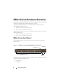 10
10
-
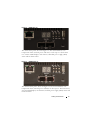 11
11
-
 12
12
-
 13
13
-
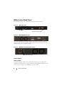 14
14
-
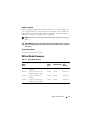 15
15
-
 16
16
-
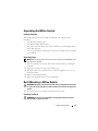 17
17
-
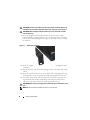 18
18
-
 19
19
-
 20
20
-
 21
21
-
 22
22
-
 23
23
-
 24
24
-
 25
25
-
 26
26
-
 27
27
-
 28
28
-
 29
29
-
 30
30
-
 31
31
-
 32
32
-
 33
33
-
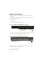 34
34
-
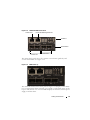 35
35
-
 36
36
-
 37
37
-
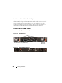 38
38
-
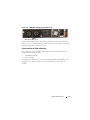 39
39
-
 40
40
-
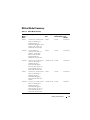 41
41
-
 42
42
-
 43
43
-
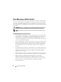 44
44
-
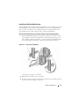 45
45
-
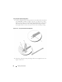 46
46
-
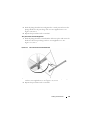 47
47
-
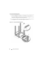 48
48
-
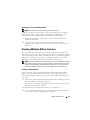 49
49
-
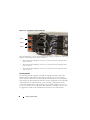 50
50
-
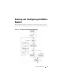 51
51
-
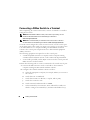 52
52
-
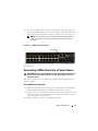 53
53
-
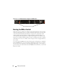 54
54
-
 55
55
-
 56
56
-
 57
57
-
 58
58
-
 59
59
-
 60
60
-
 61
61
-
 62
62
-
 63
63
-
 64
64
-
 65
65
-
 66
66
-
 67
67
-
 68
68
-
 69
69
-
 70
70
-
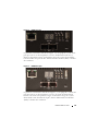 71
71
-
 72
72
-
 73
73
-
 74
74
-
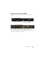 75
75
-
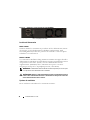 76
76
-
 77
77
-
 78
78
-
 79
79
-
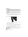 80
80
-
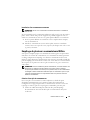 81
81
-
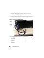 82
82
-
 83
83
-
 84
84
-
 85
85
-
 86
86
-
 87
87
-
 88
88
-
 89
89
-
 90
90
-
 91
91
-
 92
92
-
 93
93
-
 94
94
-
 95
95
-
 96
96
-
 97
97
-
 98
98
-
 99
99
-
 100
100
-
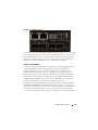 101
101
-
 102
102
-
 103
103
-
 104
104
-
 105
105
-
 106
106
-
 107
107
-
 108
108
-
 109
109
-
 110
110
-
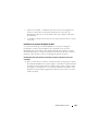 111
111
-
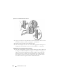 112
112
-
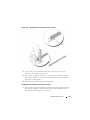 113
113
-
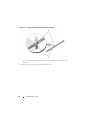 114
114
-
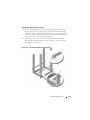 115
115
-
 116
116
-
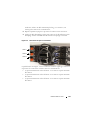 117
117
-
 118
118
-
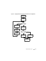 119
119
-
 120
120
-
 121
121
-
 122
122
-
 123
123
-
 124
124
-
 125
125
-
 126
126
-
 127
127
-
 128
128
-
 129
129
-
 130
130
-
 131
131
-
 132
132
-
 133
133
-
 134
134
-
 135
135
-
 136
136
-
 137
137
-
 138
138
-
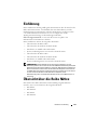 139
139
-
 140
140
-
 141
141
-
 142
142
-
 143
143
-
 144
144
-
 145
145
-
 146
146
-
 147
147
-
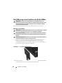 148
148
-
 149
149
-
 150
150
-
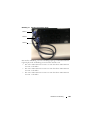 151
151
-
 152
152
-
 153
153
-
 154
154
-
 155
155
-
 156
156
-
 157
157
-
 158
158
-
 159
159
-
 160
160
-
 161
161
-
 162
162
-
 163
163
-
 164
164
-
 165
165
-
 166
166
-
 167
167
-
 168
168
-
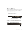 169
169
-
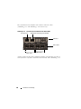 170
170
-
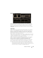 171
171
-
 172
172
-
 173
173
-
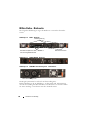 174
174
-
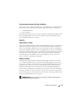 175
175
-
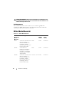 176
176
-
 177
177
-
 178
178
-
 179
179
-
 180
180
-
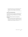 181
181
-
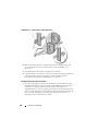 182
182
-
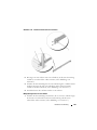 183
183
-
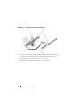 184
184
-
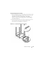 185
185
-
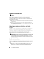 186
186
-
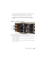 187
187
-
 188
188
-
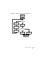 189
189
-
 190
190
-
 191
191
-
 192
192
-
 193
193
-
 194
194
-
 195
195
-
 196
196
-
 197
197
-
 198
198
-
 199
199
-
 200
200
-
 201
201
-
 202
202
-
 203
203
-
 204
204
-
 205
205
-
 206
206
-
 207
207
-
 208
208
-
 209
209
-
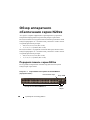 210
210
-
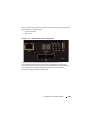 211
211
-
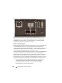 212
212
-
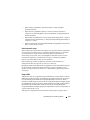 213
213
-
 214
214
-
 215
215
-
 216
216
-
 217
217
-
 218
218
-
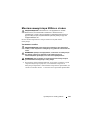 219
219
-
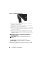 220
220
-
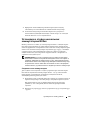 221
221
-
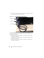 222
222
-
 223
223
-
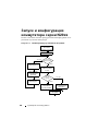 224
224
-
 225
225
-
 226
226
-
 227
227
-
 228
228
-
 229
229
-
 230
230
-
 231
231
-
 232
232
-
 233
233
-
 234
234
-
 235
235
-
 236
236
-
 237
237
-
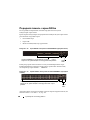 238
238
-
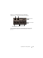 239
239
-
 240
240
-
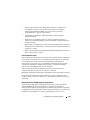 241
241
-
 242
242
-
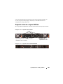 243
243
-
 244
244
-
 245
245
-
 246
246
-
 247
247
-
 248
248
-
 249
249
-
 250
250
-
 251
251
-
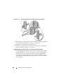 252
252
-
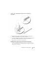 253
253
-
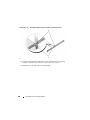 254
254
-
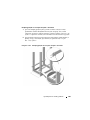 255
255
-
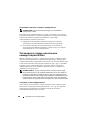 256
256
-
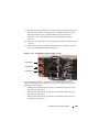 257
257
-
 258
258
-
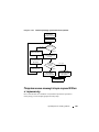 259
259
-
 260
260
-
 261
261
-
 262
262
-
 263
263
-
 264
264
-
 265
265
-
 266
266
-
 267
267
-
 268
268
-
 269
269
-
 270
270
-
 271
271
-
 272
272
-
 273
273
-
 274
274
-
 275
275
-
 276
276
-
 277
277
-
 278
278
-
 279
279
-
 280
280
-
 281
281
-
 282
282
-
 283
283
-
 284
284
-
 285
285
-
 286
286
-
 287
287
-
 288
288
-
 289
289
-
 290
290
-
 291
291
-
 292
292
-
 293
293
-
 294
294
-
 295
295
-
 296
296
-
 297
297
-
 298
298
-
 299
299
-
 300
300
-
 301
301
-
 302
302
-
 303
303
-
 304
304
-
 305
305
-
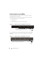 306
306
-
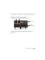 307
307
-
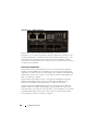 308
308
-
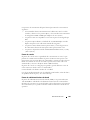 309
309
-
 310
310
-
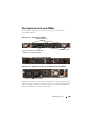 311
311
-
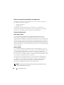 312
312
-
 313
313
-
 314
314
-
 315
315
-
 316
316
-
 317
317
-
 318
318
-
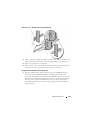 319
319
-
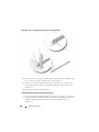 320
320
-
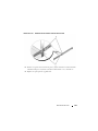 321
321
-
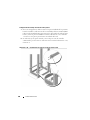 322
322
-
 323
323
-
 324
324
-
 325
325
-
 326
326
-
 327
327
-
 328
328
-
 329
329
-
 330
330
-
 331
331
-
 332
332
-
 333
333
-
 334
334
-
 335
335
-
 336
336
-
 337
337
-
 338
338
-
 339
339
-
 340
340
-
 341
341
-
 342
342
-
 343
343
-
 344
344
-
 345
345
-
 346
346
-
 347
347
-
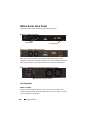 348
348
-
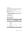 349
349
-
 350
350
-
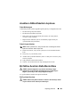 351
351
-
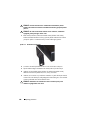 352
352
-
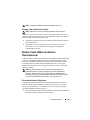 353
353
-
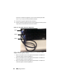 354
354
-
 355
355
-
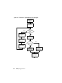 356
356
-
 357
357
-
 358
358
-
 359
359
-
 360
360
-
 361
361
-
 362
362
-
 363
363
-
 364
364
-
 365
365
-
 366
366
-
 367
367
-
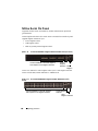 368
368
-
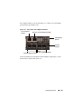 369
369
-
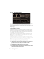 370
370
-
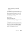 371
371
-
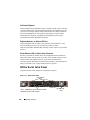 372
372
-
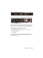 373
373
-
 374
374
-
 375
375
-
 376
376
-
 377
377
-
 378
378
-
 379
379
-
 380
380
-
 381
381
-
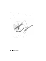 382
382
-
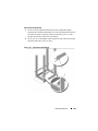 383
383
-
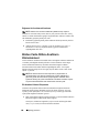 384
384
-
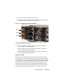 385
385
-
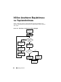 386
386
-
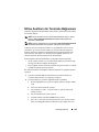 387
387
-
 388
388
-
 389
389
-
 390
390
-
 391
391
-
 392
392
-
 393
393
-
 394
394
-
 395
395
-
 396
396
-
 397
397
-
 398
398
-
 399
399
-
 400
400
-
 401
401
-
 402
402
-
 403
403
-
 404
404
-
 405
405
-
 406
406
-
 407
407
-
 408
408
-
 409
409
-
 410
410
-
 411
411
-
 412
412
-
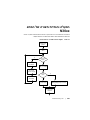 413
413
-
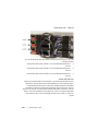 414
414
-
 415
415
-
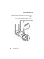 416
416
-
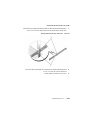 417
417
-
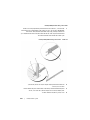 418
418
-
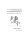 419
419
-
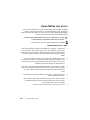 420
420
-
 421
421
-
 422
422
-
 423
423
-
 424
424
-
 425
425
-
 426
426
-
 427
427
-
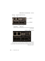 428
428
-
 429
429
-
 430
430
-
 431
431
-
 432
432
-
 433
433
-
 434
434
-
 435
435
-
 436
436
-
 437
437
-
 438
438
-
 439
439
-
 440
440
-
 441
441
-
 442
442
-
 443
443
-
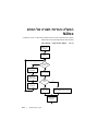 444
444
-
 445
445
-
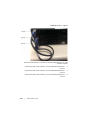 446
446
-
 447
447
-
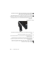 448
448
-
 449
449
-
 450
450
-
 451
451
-
 452
452
-
 453
453
-
 454
454
-
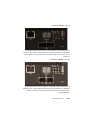 455
455
-
 456
456
-
 457
457
-
 458
458
-
 459
459
-
 460
460
-
 461
461
-
 462
462


Dell N20XX Manual de usuario
- Categoría
- Conmutadores de red
- Tipo
- Manual de usuario
- Este manual también es adecuado para
en otros idiomas
- français: Dell N20XX Manuel utilisateur
- Türkçe: Dell N20XX Kullanım kılavuzu
