Amazon B010QZCT5W Manual de usuario
- Categoría
- Soportes de pared para panel plano
- Tipo
- Manual de usuario

AmazonBasics Wall Mount Arm
Bras de montage mural AmazonBasics
AmazonBasics Wandmontagearm
Braccio per montaggio a parete AmazonBasics
Brazo para montaje en pared AmazonBasics
亚马逊倍思壁挂式支臂
Amazonベーシック 壁掛けアーム
B010QZCT5W

English ..................................... 3
Français ................................... 15
Deutsch ................................... 27
Italiano ..................................... 39
Español .................................... 51
.......................................... 63
....................................... 75

3
Instruction Manual • English
AmazonBasics Wall Mount Arm
Contents
Make sure that the package contains the following parts:
gg
Base
(1 pc)
Upper arm
(1 pc)
Lower arm
(1 pc)
Lag bolt
M8 x 80 mm
(2 pc)
Concrete anchor
M8 x 80mm
(2 pc)
Top and bottom
base cover
(2 pc)
Bracket cover
(1 pc)
M4 × 10 mm knob
(4 pcs)
M4 x 10 mm
(4 pcs)
M3 x 6 mm
(1 pc)
Cable tie
(2 pcs)
4 mm Allen wrench
(1 pc)
2.5 mm hex wrench
(1 pc)
Instruction manual

4
Tools needed
Supported monitor weights
Your wall mount arm supports a monitor of the following weight: 5 to 25 lbs (2.3 to 11.3 kg)
Stud
Finder
Pencil Tape measure
Level
Phillips
screwdriver
Hammer
Socket wrench
with 13mm socket
Wood Stud Mounting, Ø 3/16” (5mm)
Concrete Wall Mounting, Ø 3/8” (10mm)
Drill
Safety goggles

5
Monitor adjustments
Your wall mount arm lets you adjust the monitor viewing angle, height, tilt, and orientation
(portrait or landscape).
Viewing angle Height* Tilt Orientation
*NOTE: The height range may decrease by up to 4.5” (11.4 cm) when the arm is adjusted to hold over 20 lbs. (9 kg).
Assembly Instructions
Step 1: Choose a mounting location.
Decide the height where you want to mount the base. Keep in mind that your monitor can:
• Move down 8.3 in. (20.7 cm) and up 4.7 in. (11.9 cm) from the base.
• Move 20.7 in. (52.6 cm) to the left and right of the base.
• Extend out from the wall up to 25.7 in. (65.3 cm) and atten 3.9 in. (9.9 cm) from the wall.
Step 2: Choose your wall type.
You can mount the arm to a:
• Wood stud wall. Go to “Wood stud wall mount” on page 6.
OR
• Concrete wall. Go to “Concrete wall mount” on page 7.
180°
180°
360°
13 in.
(33.0 cm)
70°
5°

6
Wood stud wall mount
Step A: Use a stud nder to locate a stud, then use a level and pencil to mark the center with a
vertical line.
Step B: Align the base with the center of the stud, then mark the top and bottom holes with a pencil.
• Step C: Use a 3/16” (5 mm) bit to drill holes that are 3.1 in. (80 mm) deep in the places you
marked in the previous step.

7
Step D: Align the base with the holes, then use a socket wrench with a 13 mm socket to insert the
two M8 × 80 mm lag bolts.
Step E: Continue to “Step 3: Determine the orientation of the monitor” on page 10.
Concrete wall mount
WARNING: Mounting holes must be located within solid concrete, not mortar or covering material. If you drill into an
area of concrete that is not solid, reposition mounting holes until both anchors can be fully inserted into solid concrete.
Anchors that are not fully set in solid concrete will not support the applied load resulting in an unstable, unsafe condition
which could lead to personal injury and/or property damage. Consult a construction professional if you have any doubt
about what this means in regard to your particular situation.
Step A: Use a level and pencil to draw a vertical line where you want to locate the mount.

8
Step B: Align the base with the vertical line, then mark the top and bottom holes with a pencil.
Step C: Use a 3/8” (10 mm) masonry bit to drill 3-1/8” holes in the places you marked in the previous
step.

9
Step D: Use a hammer to insert the concrete anchors. They should be ush against the wall.
Step E: Align the base with the holes, then use a socket wrench with a 13 mm socket to insert the
two M8 × 80 mm lag bolts.

10
Step 3: Determine the orientation of the monitor
You can mount the monitor in a locked portrait or landscape orientation, or you can leave the
monitor free to rotate 360°.
• If you want the monitor to rotate freely, do not insert the M3 x 6 mm screw.
• If you want the monitor in a locked orientation, insert the M3 x 6 mm screw into the front of the
plate on the upper arm.
NOTE: If you insert the screw, then want to change the monitor’s orientation after you mount the monitor to the upper
arm, you need to remove the monitor from the upper arm and insert or remove the M3 x 6 mm screw.
Step 4: Determine the orientation of the monitor
Attach the upper arm to the back of your monitor with either the M4 × 10 mm screws and a Phillips
screwdriver or the M4 × 10 knobs. Hand-tighten the knobs.
NOTE: If a stand is attached to the monitor, remove the stand.
Caution: The mounting screw holes on the back of the monitor
may require screws of a different type or length than the provided
M4 × 10 mm screws or knobs.
• Using screws of that are too big in diameter will damage the
screw holes on the monitor.
• Using screws that are too small or too short may cause the
monitor to fall off the arm.
• Using screws that are too long may damage the interior of the
monitor.
Before you attach the monitor to the upper arm, make sure that
the provided screws or knobs t the screw holes on the back of
the monitor. If the provided screws or knobs do not t, refer to the
documentation that came with the monitor for the correct screw
type and size.

11
M4 × 10 mm screws OR M4 × 10 mm knobs
Caution: The upper arm is under tension and will move
up rapidly, on its own, as soon as the attached monitor is
removed. For this reason, remove the upper arm, lay the
monitor face down on a soft surface, then remove the monitor.
Failure to follow this instruction may result in serious personal
injury or equipment damage.
Step 5: Attach the base covers and lower arm.
Step A: Slide the top and bottom base covers onto the base until they snap into place.
Step B: Slide the lower arm onto the base.
Step C: Slide the upper arm over the lower arm, then insert the bracket cover into the top of the
upper arm. The cover should snap into place.
NOTE: To remove the bracket cover, use a athead screwdriver to pry off the cover.

12
NOTE: If you want the arm to be shorter, attach the upper arm directly to the base.
Step 6: Attach the base covers and lower arm.
Route the monitor cables along the upper arm, then loosely secure the cables to the upper arm with
the cable ties. Do not over-tighten the ties. If the ties are too tight and you try to remove them, you
may damage the monitor cables.
Squeeze the tabs on the lower arm cover to remove the cover, route the monitor cables along
the bottom of the lower arm, then replace the covers.
Caution: Before you tighten the cable ties, adjust your monitor to
the highest position. This will leave enough slack in the cables for
monitor movement/height adjustment.

13
Step 7: Adjust your wall mount arm’s tension.
You can adjust the vertical, tilt, and arm tension so that the monitor stays in place when you move it.
Adjusting the vertical tension
Tilt the monitor down to access the screw. If the monitor is rising up, loosen the screw by
turning it to the left. If the monitor is falling down, tighten the screw by turning it to the right.
Caution: Do not over-tighten the screw. You might damage the
monitor or your wall mount arm.
Adjusting the tilt tension
If the monitor is falling forward (screen goes down), loosen the screw by turning it to the left. If
the monitor is falling back (screen goes up), tighten the screw by turning it to the right.
Caution: Do not remove the screw. The monitor might fall.
Do not over-tighten the screw. You might damage the monitor or
your wall mount arm.

14
Adjusting the arm tension
To make the arm easier to move, loosen the screws by turning them to the left. To make the
arm harder to move, tighten the screws by turning them to the right.
Caution: Do not remove the screws. The monitor might fall.
Do not over-tighten the screws. You might damage the monitor or
your wall mount arm.
Safety and Compliance
IMPORTANT: This product will need tension adjustments after installation is complete. Make
sure that all equipment is properly installed on the product before attempting range of motion
or tension adjustments. Any time equipment is added or changed on this product resulting in a
different mounted weight, you should repeat the adjustment steps to ensure safe and optimum
operation. This product should move smoothly and easily through the full range of motion and
stay where you set it. If movement is dif cult or the product does not stay where you set it,
follow the adjustment instructions to loosen or tighten the tension to create a smooth, easy
motion. Depending on your product and the adjustment, it may take many turns to notice a
difference.
© 2015 Amazon.com, Inc. or its affiliates. All Rights reserved. Amazon and the AmazonBasics logo are trademarks of
Amazon.com, Inc. or its affiliates. Made in China

15
Manuel d’instructions • Français
Bras de montage mural AmazonBasics
Contenu
Assurez-vous que l'emballage contient les pièces suivantes:
g
Base
(1)
Bras supérieur
(1)
Bras inférieur
(1)
Tire-fond
M8 x 80 mm
(2)
Ancrage pour béton
M8 x 80 mm
(2)
Couvercles supérieur
et inférieur de la base
(2)
Couvercle
du support
(1)
Bouton M4 × 10 mm
(4)
M4 x 10 mm
(4)
M3 x 6 mm
(1)
Attache de câble
(2)
Clé mâle à six pans
de 4 mm
(1)
Clé hexagonale de 2,5mm
(1)
Manuel d’instructions

16
Outillage nécessaire
Poids d'écran supportés
Votre bras de montage mural supporte un écran d'un poids compris dans les valeurs suivantes: 2,3
à 11,3 kg (5 à 25 lb)
Localisateur
de montants
Crayon Ruban à mesurer
Niveau
Tournevis
cruciforme
Marteau
Clé à douille
de 13 mm
Montage sur montant, Ø 5 mm (3/16 po)
Montage sur mur en béton,
Ø 10 mm (3/8 po)
Perceuse
Lunettes de protection

17
Ajustements de l'écran
Votre bras de montage mural vous permet d'ajuster l'angle de visionnement, la hauteur, l'inclinaison
et l'orientation (portrait ou paysage) de l'écran.
Angle de visualisation Hauteur* Inclinaison Orientation
* REMARQUE : La plage de hauteur peut être diminuée de 11,4 cm (4,5 po) quand le bras est ajusté pour soutenir plus
de 9 kg (20 lb).
Instructions d'assemblage
Étape1: Choix d'un emplacement de montage.
Décidez de la hauteur à laquelle vous voulez monter la base. N’oubliez pas que l'écran peut:
• se déplacer vers le bas de 20,7 cm (8,3 po) et vers le haut de 11,9 cm (4,7 po) de la base.
• se déplacer de 52,6 cm (20,7 po) sur la gauche et la droite de la base.
• se déployer jusqu'à 65,3 (25,7 po) et se rétracter à 9,9cm (3,9 po) du mur.
Étape2: Choix du type de mur.
Vous pouvez montez le bras sur :
• un mur à structure de bois. Rendez-vous à « Montage sur mur à structure de bois » à la 18.
OU
• Mur en béton. Rendez-vous à « Montage sur mur en béton » à la page 19.
180˚
180˚
360˚
33 cm
(13 po)
70°
5°

18
Montage sur mur à structure de bois
Étape A : Recherchez un montant à l'aide d'un localisateur de montants et tracez une ligne verticale
au centre avec un niveau et un crayon.
Étape B : Alignez la base sur le centre du montant et marquez les trous du haut et du bas à l'aide
d'un crayon.
Étape C : Aux emplacements marqués à l'étape précédente, percez des trous d'une profondeur de
80 mm (3,1 po) avec un foret de 5 mm (3/16 po).

19
Étape D : Alignez la base sur les trous et introduisez les deux tire-fonds M8 × 80 mm à l'aide d'une
clé à douille de 13 mm.
Étape E : Continuez avec « Étape3: Détermination de l’orientation de l’écran » à la on page 21.
Montage sur mur en béton
AVERTISSEMENT: Les trous de montage doivent se trouver dans le béton plein, et non sur le mortier ou sur le matériau
de revêtement. Si vous percez dans une zone de béton non plein, repositionnez les trous de montage jusqu'à ce que
les deux ancrages puissent être entièrement introduits dans du béton plein. Les ancrages qui ne sont pas entièrement
placés dans du béton plein ne supporteront pas la charge appliquée et provoqueront une condition instable et
dangereuse pouvant entraîner des blessures ou des dégâts matériels. Consultez un professionnel du bâtiment en cas de
doute sur ce que cela signi e dans votre cas particulier.
Étape A : Tracez une ligne verticale sur l'emplacement d'installation du support à l'aide d'un niveau
et d'un crayon.

20
Étape B : Alignez la base sur la ligne verticale et marquez les trous du haut et du bas à l'aide d'un
crayon.
Étape C : Aux emplacements marqués à l'étape précédente, percez des trous de 80 mm (3,1 po)
avec un foret de maçonnerie de 10 mm (3/8 po).

21
Étape D : Enfoncez les ancrages pour béton à l'aide d'un marteau. Ils doivent être à ras avec le mur.
Étape E : Alignez la base sur les trous et introduisez les deux tire-fonds M8 × 80 mm à l'aide d'une
clé à douille de 13 mm.

22
Étape3: Détermination de l'orientation de l'écran
L'écran peut être monté dans un sens verrouillé de portrait ou de paysage, ou libre de pivoter sur
360°.
• Si vous voulez que l'écran pivote librement, ne posez pas la vis M3 x 6 mm.
• Si vous voulez que l'orientation de l'écran soit verrouillée, posez la vis M3 x 6 mm à l'avant de la
plaque sur le bras supérieur.
REMARQUE: Si vous posez la vis et que vous voulez changer l'orientation de l'écran après l'avoir monté sur le bras
supérieur, vous devrez déposer l'écran du bras supérieur et poser ou retirer la vis M3 x 6 mm.
Étape4: Détermination de l'orientation de l'écran
Fixez le bras supérieur sur l'arrière de l'écran avec les vis M4 × 10 mm et un tournevis à tête
cruciforme ou avec les boutons M4 × 10. Serrez les boutons à la main.
REMARQUE: Si un socle est xé sur l'écran, déposez-le.
Attention: Les trous de vis de montage sur l'arrière de l'écran
peuvent nécessiter des vis d'un type ou d'une longueur différents
que les vis ou boutons M4 × 10 mm fournis.
• L'utilisation de vis d'un diamètre excessif endommagera les
trous de vis sur l'écran.
• L'utilisation de vis trop petites ou trop courtes peut entraîner la
chute de l'écran du bras.
• L'utilisation de vis trop longues peut endommager l'intérieur
de l'écran.
Avant de xer l'écran sur le bras supérieur, assurez-vous que
les vis ou boutons fournis d'adaptent dans les trous de vis sur
l'arrière de l'écran. Si les vis ou boutons fournis ne s'adaptent pas,
reportez-vous à la documentation accompagnant l'écran pour
savoir le type et la taille corrects des vis.

23
Vis M4 × 10 mm OU boutons M4 × 10 mm
Attention: Le bras supérieur est sous tension et remonte
rapidement de lui-même dès que l'écran xé est déposé.
Pour cette raison, déposez le bras supérieur, posez l'écran
la face à plat sur une surface douce et déposez l'écran.
Le non-respect de cette instructions peut provoquer des blessures
graves ou des dégâts matériels.
Étape5: Fixez les couvercle de la base et le bras inférieur.
Étape A : Faites glissez les couvercles supérieur et inférieur de la base sur cette dernière jusqu'à ce
qu'ils s'emboîtent en place.
Étape B : Faite glisser le bras inférieur sur la base.
Étape C : Faites glisser le bras supérieur au-dessus du bras inférieur et introduisez le couvercle du
support dans le haut du bras supérieur. Le couvercle doit s'emboîter en place.
REMARQUE: Pour déposer le couvercle du support, utilisez un tournevis plat pour le soulever.

24
REMARQUE: Si vous voulez que le bras soit plus court, xez le bras supérieur directement sur la base.
Étape6: Fixez les couvercle de la base et le bras inférieur.
Acheminez les câbles de l'écran le long du bras supérieur et xez les câbles sans les serrer sur
ce bras avec des attaches de câbles. Ne serrez pas trop les attaches. En cas de serrage excessif
des attaches de câbles et que vous tentez de les déposer, les câbles de l'écran risquent de
s'endommager.
Appuyez sur les pattes sur le couvercle du bras inférieur pour déposer le couvercle, acheminez les
câbles de l'écran le long du bas du bras inférieur et remettez les couvercles en place.
Attention: Réglez l'écran sur la position la plus haute avant de
serrer les attaches de câbles. Laisser assez de mou dans les
câbles pour permettre un déplacement de l'écran et un réglage de
la hauteur.

25
Étape7: Réglage de la tension du bras de montage mural
Vous pouvez régler la tension verticale, d'inclinaison et du bras a n que l'écran reste en place quand
vous le déplacez.
Réglage de la tension verticale
Inclinez l'écran vers le bas pour accéder à la vis. Si l'écran remonte, desserrez la vis en la tournant
vers la gauche. Si l'écran tombe, serrez la vis en la tournant vers la droite.
Attention: Ne serrez pas trop la vis. L'écran ou le bras de
montage mural pourrait s'endommager.
Réglage de la tension d'inclinaison
Si l'écran penche vers l'avant (il descend), desserrez la vis en la tournant vers la gauche. Si l'écran
penche vers l'arrière (il remonte), serrez la vis en la tournant vers la droite.
Attention: N'enlevez pas la vis. L'écran pourrait tomber.
Ne serrez pas trop la vis. L'écran ou le bras de montage mural
pourrait être endommagé.

26
Réglage de la tension du bras
Pour faciliter le déplacement du bras, desserrez les vis en les tournant vers la gauche. Pour rendre le
déplacement du bras plus dur, serrez les vis en les tournant vers la droite.
Attention: N'enlevez pas les vis. L'écran pourrait tomber.
Ne serrez pas trop les vis. L'écran ou le bras de montage mural
pourrait être endommagé.
Sécurité et conformité
IMPORTANT: Ce produit nécessite des réglages de la tension une fois l’installation terminée.
Assurez-vous que tous les équipements sont correctement installés sur le produit avant d’essayer
les réglages de l’amplitude de déplacement ou de la tension. Chaque fois qu’un équipement est
ajouté ou changé sur ce produit et en modi e le poids monté, répétez les étapes de réglage a n
d’assurer un fonctionnement sûr et optimum. Ce produit doit se déplacer en douceur et facilement
sur toute l’amplitude et rester à l’emplacement où vous le laissez.
Si le déplacement est dif cile ou si le produit ne reste pas en place, suivez les instructions de
réglage pour augmenter ou réduire la tension a n de créer un déplacement en douceur et facile.
En fonction de votre produit et du réglage, plusieurs tours de vis peuvent être nécessaires pour
qu’une différence soit remarquée.
© 2015 Amazon.com, Inc. ou ses filiales. Tous droits réservés. Amazon et le logo AmazonBasics sont des marques
commerciales d'Amazon.com, Inc. ou de ses filiales. Fabriqué en Chine

27
Bedienungsanleitung • Deutsch
AmazonBasics Wandmontagearm
Inhalt
Vergewissern Sie sich, dass die Verpackung die folgenden Teile enthält:
ggg
Sockel
(1 Stk)
Oberer Arm
(1 Stk)
Unterer Arm
(1 Stk)
Schlüsselschraube
M8 x 80 mm
(2 Stk)
Betondübel
M8 x 80 mm
(2 Stk)
Obere und untere
Sockelabdeckung
(2 Stk)
Halterungsabdeckung
(1 Stk)
M4 × 10-mm
Knopfdrehschraube
(4 Stk)
M4 x 10 mm
(4 Stk)
M3 x 6 mm
(1 Stk)
Kabelbinder
(2 Stk)
4-mm-Inbusschlüssel
(1 Stk)
2,5-mm-
Sechskantschlüssel
(1 Stk)
Bedienungsanleitung

28
Benötigtes Werkzeug
Unterstützte Monitorgewichte
Ihr Wandmontagearm trägt Monitore im folgenden Gewichtsbereich: 2,3 bis 11,3kg
Balken-
sucher
Bleistift Maßband
Wasserwaage
Kreuzschlitz-
schraubendreher
Hammer
Steckschlüssel
mit 13-mm-Einsatz
Holzpfostenmontage, 5 mm Ø
Betonwandmontage, 10 mm Ø
Bohrer
Schutzbrille

29
Monitoreinstellungen
Ihr Wandmontagearm ermöglicht das Einstellen des Betrachtungswinkels, der Höhe, der Neigung
und der Ausrichtung (Hoch- oder Querformat) Ihres Monitors.
Betrachtungswinkel Höhe* Neigung Ausrichtung
*HINWEIS: Die maximale Höhe kann um bis zu 11,4 cm reduziert werden, wenn der Arm für ein Gewicht von über 9kg
justiert wird.
Montageanleitung
Schritt 1: Bestimmen Sie, an welcher Stelle der Montagearm angebracht werden soll.
Bestimmen Sie, in welcher Höhe Sie den Sockel befestigen möchten. Beachten Sie dabei
Folgendes:
• Der Monitor kann um 20,7cm unter und um 11,9cm über den Sockel bewegt werden.
• Der Monitor kann um 52,6cm nach links und nach rechts vom Sockel bewegt werden.
• Der Monitor kann um bis zu 65,3cm von der Wand ausgefahren und auf einen Abstand von
9,9cm zur Wand eingefahren werden.
Schritt 2: Bestimmen Sie, welche Art von Wand Sie haben.
Sie können den Arm an den folgenden Wand ächen anbringen:
• einer Holzpfostenwand – siehe „Montage an einer Holzpfostenwand” auf Seite 30.
ODER
• einer Betonwand – siehe „Montage an einer Betonwand” auf Seite 31.
180°
180°
360°
33,0 cm
70°
5°

30
Montage an einer Holzpfostenwand
Schritt A: Bestimmen Sie den Verlauf eines Pfostens mit einem Balkensucher und markieren Sie
mithilfe eines Bleistifts und einer Wasserwaage die Pfostenmitte mit einer
senkrechten Linie.
Schritt B: Richten Sie den Sockel mit der Mitte des Pfostens aus und markieren Sie die obere und
untere Bohrung mit einem Bleistift.
Schritt C: Bohren Sie mit einem 5-mm-Bohrer Löcher bis zu einer Tiefe von 80mm an den im
vorherigen Schritt markierten Stellen.

31
Schritt D: Bringen Sie den Sockel mit den Löchern zur Deckung und schrauben Sie dann mit einem
Steckschlüssel mit einem 13-mm-Einsatz die zwei M8 × 80-mm-Schlüsselschrauben ein.
Schritt E: Weiter mit „Schritt 3: Bestimmen Sie die Ausrichtung des Monitors” auf Seite 34.
Montage an einer Betonwand
WARNUNG: Die Montagelöcher müssen in Massivbeton gebohrt werden; Mörtel oder Deckmaterialien sind nicht
geeignet. Wenn Sie mit dem Bohrer einen nicht massiven Teil des Betons erreichen, ändern Sie die Position der
Montagelöcher, bis beide Dübel vollständig in Massivbeton eingesetzt werden können. Nicht vollständig in Massivbeton
eingeschlagene Dübel können die aufgebrachte Last nicht tragen, was einen instabilen, unsicheren Zustand bewirkt, der
Verletzungen und/oder Sachschäden zur Folge haben kann. Lassen Sie sich von einem Baufachmann beraten, wenn Sie
sich nicht sicher sind, was das für Ihre spezi sche Situation bedeutet.
Schritt A: Zeichnen Sie mithilfe einer Wasserwaage und eines Bleistifts eine senkrechte Linie an der
Stelle, an der der Montagearm angebracht werden soll.

32
Schritt B: Richten Sie den Sockel mit der senkrechten Linie aus und markieren Sie die obere und
untere Bohrung mit einem Bleistift.
Schritt C: Bohren Sie mit einem 10-mm-Mauerbohrer 80mm tiefe Löcher an den im vorherigen
Schritt markierten Stellen.

33
Schritt D: Schlagen Sie die Betondübel mit einem Hammer ein. Sie müssen bündig mit der Wand
abschließen.
Schritt E: Bringen Sie den Sockel mit den Löchern zur Deckung und schrauben Sie dann mit einem
Steckschlüssel mit einem 13-mm-Einsatz die zwei M8 × 80-mm-Schlüsselschrauben ein.

34
Schritt 3: Bestimmen Sie die Ausrichtung des Monitors.
Sie können den Monitor in einer arretierten Hoch- oder Querformatausrichtung montieren oder ihn so
anbringen, dass er sich ungehindert um 360° drehen lässt.
• Wenn sich der Monitor ungehindert drehen lassen soll, setzen Sie die M3 x 6-mm-Schraube nicht
ein.
• Wenn die Monitorausrichtung xiert werden soll, setzen Sie die M3 x 6-mm-Schraube vorne in
die Platte im oberen Arm ein.
HINWEIS: Wenn Sie nach dem Einsetzen der Schraube und der Montage des Monitors am oberen Arm die Ausrichtung
des Monitors verändern möchten, müssen Sie den Monitor vom oberen Arm abnehmen und die M3 x 6-mm-Schraube
entweder einsetzen oder entfernen.
Schritt 4: Bestimmen Sie die Ausrichtung des Monitors.
Befestigen Sie den oberen Arm mit den M4 x 10-mm-Schrauben und einem
Kreuzschlitzschraubendreher oder den M4 × 10-Knopfdrehschrauben an der Rückseite des
Monitors. Ziehen Sie die Knopfdrehschrauben von Hand an.
HINWEIS: Wenn am Monitor ein Ständer befestigt ist, muss dieser entfernt werden.
Vorsicht: Die Montageschraubenbohrungen auf der Rückseite des
Monitors erfordern eventuell Schrauben einer anderen Art oder
Länge als die im Lieferumfang enthaltenen
M4 × 10-mm-Schrauben oder Knopfdrehschrauben.
• Bei einem Gebrauch von Schrauben mit einem zu großen
Durchmesser werden die Schraubenbohrungen am Monitor
beschädigt.
• Der Gebrauch von zu kleinen oder zu kurzen Schrauben kann
ein Herunterfallen des Monitors vom Arm verursachen.
• Bei einem Gebrauch von zu langen Schrauben kann das
Innere des Monitors beschädigt werden.
Achten Sie vor dem Befestigen des Monitors am oberen Arm
darauf, dass die im Lieferumfang enthaltenen Schrauben bzw.
Knopfdrehschrauben in die Schraubenbohrungen auf der
Rückseite des Monitors passen. Wenn die im Lieferumfang
enthaltenen Schrauben bzw. Knopfdrehschrauben nicht passen,
suchen Sie in der dem Monitor beiliegenden Dokumentation nach
der richtigen Schraubenart und -größe.

35
M4 × 10-mm-Schrauben ODER M4 × 10-mm-Knopfdrehschrauben
Vorsicht: Der obere Arm ist vorgespannt und bewegt sich
eigenständig schnell nach oben, sobald der daran angebrachte
Monitor entfernt wird. Entfernen Sie daher zuerst den oberen Arm,
legen den Monitor mit dem Bildschirm nach unten auf einer
weichen Ober äche ab und nehmen erst dann den Monitor
vom Arm ab. Ein Missachten dieser Anleitung kann schwere
Verletzungen und Geräteschäden zur Folge haben.
Schritt 5: Bringen Sie die Sockelabdeckungen und den unteren Arm an.
Schritt A: Schieben Sie die obere und untere Sockelabdeckung über den Sockel, bis beide
einrasten.
Schritt B: Schieben Sie den unteren Arm auf den Sockel.
Schritt C: Schieben Sie den oberen Arm über den unteren Arm und stecken Sie dann die
Halterungsabdeckung oben in den oberen Arm hinein. Die Abdeckung sollte einrasten.
HINWEIS: Verwenden Sie zum Entfernen der Halterungsabdeckung einen Flachschraubendreher, mit dem Sie die
Abdeckung abstemmen.

36
HINWEIS: Wenn der Arm kürzer sein soll, befestigen Sie den oberen Arm direkt am Sockel.
Schritt 6: Bringen Sie die Sockelabdeckungen und den unteren Arm an.
Führen Sie die Monitorkabel am oberen Arm entlang und sichern Sie sie mit den Kabelbindern lose
am oberen Arm. Die Kabelbinder nicht zu fest zuziehen. Wenn die Binder zu fest sitzen und Sie
versuchen, sie zu entfernen, können die Monitorkabel beschädigt werden.
Drücken Sie die Zungen auf der Abdeckung des oberen Armes zusammen, um die Abdeckung
abzunehmen; führen Sie die Monitorkabel unten am unteren Arm entlang und bringen Sie die
Abdeckung wieder an.
Vorsicht: Bringen Sie den Monitor in seine oberste Position,
bevor Sie die Kabelbinder festziehen. Damit verbleibt ein
ausreichender Kabeldurchhang für die
Monitorbewegungen/Höheneinstellungen.

37
Schritt 7: Stellen Sie die Spannung des Wandmontagearms ein.
Sie können die senkrechte, Neigungs- und Armspannung so einstellen, dass der Monitor in der
Position verharrt, in die Sie ihn verschieben.
Einstellen der senkrechten Spannung
Neigen Sie den Monitor nach unten, damit die Schraube zugänglich wird. Wenn sich der Monitor
wieder aufrichtet, lockern Sie die Schraube, indem Sie sie nach links drehen. Wenn der Monitor nach
unten kippt, ziehen Sie die Schraube an, indem Sie sie nach rechts drehen.
Vorsicht: Die Schraube nicht zu fest anziehen. Dadurch können
der Monitor oder der Wandmontagearm beschädigt werden.
Einstellen der Neigungsspannung
Wenn der Monitor nach vorne fällt (wobei sich der Bildschirm nach unten neigt), lockern Sie die
Schraube, indem Sie sie nach links drehen. Wenn der Monitor nach hinten kippt (wobei sich der
Bildschirm aufrichtet), ziehen Sie die Schraube an, indem Sie sie nach rechts drehen.
Vorsicht: Die Schraube nicht entfernen. Der Monitor könnte
herunterfallen. Die Schraube nicht zu fest anziehen. Dadurch
können der Monitor oder der Wandmontagearm beschädigt
werden.

38
© 2015 Amazon.com, Inc. oder seine verbundenen Unternehmen. Alle Rechte vorbehalten. Amazon und das
AmazonBasics-Logo sind Marken von Amazon.com, Inc. oder seinen verbundenen Unternehmen. Made in China
Einstellen der Armspannung
Um den Arm leichter bewegen zu können, lockern Sie die Schrauben, indem Sie sie nach links
drehen. Um den Widerstand beim Bewegen des Armes zu erhöhen, ziehen Sie die Schrauben an,
indem Sie sie nach rechts drehen.
Vorsicht: Die Schrauben nicht entfernen. Der Monitor könnte
herunterfallen. Die Schrauben nicht zu fest anziehen. Dadurch
können der Monitor oder der Wandmontagearm beschädigt
werden.
Sicherheit und Regelkonformität
WICHTIG: Nach Abschluss der Installation muss die Spannung an diesem Produkt justiert werden.
Stellen Sie sicher, dass alle Geräte sachgemäß an dem Produkt montiert wurden, bevor Sie
versuchen, den Bewegungsradius oder die Spannung einzustellen. Wenn an diesem Produkt neue
Geräte angebracht werden oder Veränderungen an den angebrachten Geräten vorgenommen
werden, die ein anderes Montagegewicht zur Folge haben, sollten Sie die Schritte zur Einstellung
wiederholen, um eine sichere und optimale Funktion sicherzustellen. Dieses Produkt sollte sich über
seinen gesamten Bewegungsradius hinweg ruckfrei und mühelos bewegen lassen und in seiner
Zielposition verharren. Wenn sich das Produkt nur schwer bewegen lässt oder es nicht in seiner
Zielposition verbleibt, reduzieren oder erhöhen Sie die Spannung gemäß der Einstellanleitung, um
gleichmäßige, einfache Bewegungen zu erzeugen. Je nach dem Produkt und seiner Einstellung
können viele Schraubendrehungen erforderlich sein, bevor Sie einen Unterschied bemerken.

39
Manuale d’istruzioni • Italiano
Braccio per montaggio a parete AmazonBasics
Contenuto
Accertarsi che l’imballaggio contenga i seguenti componenti:
gg g g
Base
(1 pz)
Parte superiore
braccio
(1 pz)
Parte inferiore
braccio
(1 pz)
Vite per legno
M8 x 80 mm
(2 pz)
Tassello per
calcestruzzo
M8 x 80 mm
(2 pz)
Coperchio base
superiore e inferiore
(2 pz)
Coperchio staffa
(1 pz)
Vite a testa zigrinata
M4 × 10 mm
(4 pz)
M4 x 10 mm
(4 pz)
M3 x 6 mm
(1 pz)
Fascetta
(2 pz)
Chiave esagonale da 4 mm
(1 pz)
Chiave esagonale da
2,5 mm
(1 pz)
Manuale di istruzioni

40
Attrezzi necessari
Pesi del monitor supportati
Il braccio per montaggio a parete può sostenere un monitor avente il seguente peso: da 2,3 a 11,3
kg.
Rilevatore
di montanti
Matita Rotella metrica
Livella
Cacciavite
con testa a croce
Martello
Chiave a bussola
con bussola di 13 mm
Fissaggio su montante in legno, Ø 3/16”
(5 mm)
Fissaggio su parete di calcestruzzo, Ø
3/8” (10 mm)
Trapano
Occhiali di sicurezza

41
Regolazioni del monitor
Il braccio per montaggio a parete consente di regolare l’angolazione, l’altezza, l’inclinazione e
l’orientamento (verticale o orizzontale) del monitor.
Angolazione Altezza* Inclinazione Orientamento
*NOTA. L’intervallo di regolazione dell’altezza può essere ridotto di un massimo di 11,4 cm quando il braccio è regolato
in modo da sostenere oltre 9 kg.
Istruzioni per il montaggio
1. Scegliere una posizione di fi ssaggio.
Stabilire l’altezza alla quale si desidera ssare la base. Tenere presente che il monitor può:
• essere mosso verso il basso di 20,7 cm e verso l’alto di 11,9 cm rispetto alla base;
• essere mosso di 52,6 cm a sinistra e a destra della base;
• essere esteso no a 65,3 cm dalla parete ed essere avvicinato sino a 9,9 cm.
2. Determinare il tipo di parete.
Il braccio può essere ssato a:
• una parete di legno; in tal caso andare a “ Fissaggio a una parete con montanti di legno” a
pagina 42.
OPPURE
• a una parete di calcestruzzo; in tal caso andare a “ Fissaggio a una parete di calcestruzzo” a
pagina 43.
180°
180°
360°
13”
(33,0 cm)
70°
5°

42
Fissaggio a una parete con montanti di legno
A. Usare un apposito rilevatore per individuare uno dei montanti, quindi contrassegnarne il centro
tracciando con una matita una linea verticale avvalendosi di una livella.
B. Allineare la base con il centro del montante, quindi contrassegnare i fori superiore e inferiore con
una matita.
C. Usare una punta da trapano da 3/16” (5 mm) per praticare fori di 80 mm di profondità nei punti
contrassegnati al passaggio B.

43
D. Allineare la base ai fori, quindi usare una chiave con bussola di 13 mm per inserire le
due viti da legno M8 × 80 mm.
E. Andare a “ 3. Determinare l’orientamento del monitor” a pagina 45.
Fissaggio a una parete di calcestruzzo
ATTENZIONE. I fori di ssaggio devono essere praticati nel calcestruzzo pieno, non nella malta né in materiale di
rivestimento; se li si pratica in un’area della parete che risulta non essere di calcestruzzo pieno, rieseguirli in un’area
diversa nché non è possibile introdurre completamente entrambi i tasselli nel calcestruzzo pieno. Tasselli non inseriti
bene nel calcestruzzo pieno non sosterrebbero il carico applicato; ne conseguirebbe una condizione non sicura, di
instabilità che potrebbe causare lesioni personali e/o danni alle cose. Rivolgersi a un installatore quali cato se si hanno
dubbi riguardo a una particolare situazione.
A. Tracciare con una matita, avvalendosi di una livella, una linea verticale nell’area in cui si vuole
ssare il braccio.

44
B. Allineare la base alla linea verticale, quindi contrassegnare i fori superiore e inferiore con una
matita.
C. Usare una punta da trapano per calcestruzzo di 3/8” (10 mm) per praticare fori di 79,4 mm di
profondità nei punti contrassegnati al passaggio B.
D. Usare un martello per inserire i tasselli da calcestruzzo nché non sono a lo contro la parete.

45
E. Allineare la base ai fori, quindi usare una chiave con bussola di 13 mm per inserire le
due viti da legno M8 × 80 mm.
3. Determinare l’orientamento del monitor
Si può montare il monitor orientandolo in verticale o in orizzontale e bloccandolo, oppure lasciarlo
libero di ruotare di 360°.
• Se si desidera che il monitor possa essere ruotato, non inserire la vite M3 x 6 mm.
• Se si desidera bloccare il monitor in un determinato orientamento, inserire la vite M3 x 6 mm
nella parte anteriore della piastra sulla parte superiore del braccio.
NOTA. Se si inserisce la vite e successivamente si desidera cambiare l’orientamento del monitor dopo averlo montato
sulla parte superiore del braccio, occorre prima rimuoverlo dalla parte superiore del braccio e quindi inserire o estrarre la
vite M3 x 6 mm.
4. Determinare l’orientamento del monitor
Fissare la parte superiore del braccio alla parte posteriore del monitor con le viti M4 × 10 mediante
un cacciavite con testa a croce o con le viti a testa zigrinata M4 × 10 mm, serrando queste ultime
manualmente.

46
NOTA. Se il monitor è montato su un supporto, rimuovere quest’ultimo prima di ssare il monitor alla parte superiore del
braccio.
Attenzione. I fori presenti sulla parte posteriore del monitor
possono richiedere viti di lettatura o lunghezza diversa dalle viti
con testa a croce o zigrinata M4 × 10 mm fornite.
• Utilizzando viti di diametro eccessivo si danneggerebbero i fori
già presenti nel monitor.
• Se si utilizzano viti di diametro insuf ciente o troppo corte, il
monitor potrebbe staccarsi dal braccio e cadere.
• Utilizzando viti di lunghezza eccessiva si potrebbe
danneggiare l’interno del monitor.
Prima di ssare il monitor alla parte superiore del braccio,
accertarsi che le viti con testa a croce o zigrinata fornite si
adattino ai fori presenti sulla parte posteriore del monitor; se non si
adattano perfettamente, consultare la documentazione allegata al
monitor per determinare la corretta lettatura e lunghezza delle viti.
Viti con testa a croce M4 × 10 mm OPPURE Viti a testa zigrinata M4 × 10 mm
Attenzione. La parte superiore del braccio è sotto tensione
e si muoverà spontaneamente e velocemente verso l’alto
non appena si rimuove il monitor. Procedere pertanto
rimuovendo prima la parte superiore del braccio, poggiando il
monitor con lo schermo verso il basso su una super cie morbida e
quindi rimuovendo il monitor.
La mancata osservanza di queste istruzioni può causare gravi
lesioni personali o danni alle cose.

47
5. Fissare i coperchi della base e la parte inferiore del braccio.
A. Fare scorrere i coperchi superiore e inferiore sulla base nché non si bloccano con uno scatto.
B. Fare scorrere la parte inferiore del braccio sulla base.
C. Fare scorrere la parte superiore del braccio sulla parte inferiore del braccio, quindi inserire il
coperchio della staffa sulla parte superiore del braccio nché non si blocca con uno scatto.
NOTA. Per rimuovere il coperchio della staffa, fare leva su di esso con un cacciavite a punta piatta.
NOTA. Se si desidera che il braccio sia più corto, ssarne la parte superiore direttamente alla base.

48
6. Fissare i coperchi della base e la parte inferiore del braccio.
Disporre i cavi del monitor lungo la parte superiore del braccio, quindi ssarli con le fascette
lasciando un po’ di gioco. Non stringere troppo le fascette, altrimenti quando si cerca di rimuoverle,
si potrebbero danneggiare i cavi.
Comprimere le linguette sul coperchio della parte inferiore del braccio per rimuovere il coperchio
stesso, disporre i cavi del monitor lungo la scanalatura della parte inferiore del braccio, quindi
riposizionare il coperchio.
Attenzione. Prima di stringere le fascette, regolare il monitor
alla posizione di massima altezza; si lasceranno così i cavi allentati
quanto basta per regolare l’altezza/il movimento del monitor.

49
7. Regolare la tensione del braccio.
È possibile regolare la tensione corrispondente all’altezza e all’inclinazione nonché la tensione del
braccio af nché né l’altezza né l’inclinazione varino quando si muove il monitor.
Regolazione della tensione corrispondente all’altezza
Spostare il monitor verso il basso per accedere alla vite. Se il monitor si muove verso l’alto, allentare
la vite girandola in senso antiorario. Se il monitor si muove verso il basso, serrare la vite girandola in
senso orario.
Attenzione. Non serrare eccessivamente la vite; si potrebbe
danneggiare il monitor o il braccio.
Regolazione della tensione corrispondente all’inclinazione
Se il monitor si muove in avanti (lo schermo si abbassa), allentare la vite girandola in senso
antiorario. Se il monitor si muove indietro (lo schermo si solleva), serrare la vite girandola in senso
orario.
Attenzione. Non estrarre la vite; il monitor potrebbe cadere.
Non serrare eccessivamente la vite; si potrebbe danneggiare il
monitor o il braccio.

50
Regolazione della tensione del braccio
Per muovere il braccio più facilmente, allentare le viti girandole in senso antiorario. Per far sì
che occorra esercitare una forza maggiore per muovere il braccio, serrare le viti girandole in senso
orario.
Attenzione. Non estrarre le viti; il monitor potrebbe cadere.
Non serrare eccessivamente le viti; si potrebbe danneggiare il
monitor o il braccio.
Sicurezza e conformità
NOTA BENE. Completata l’installazione di questo prodotto, è necessario eseguire regolazioni
della tensione. Veri care che il monitor sia installato correttamente sul prodotto prima di eseguire
regolazioni dell’intervallo di movimento o della tensione. Ogni volta che si modi ca o si cambia
il monitor montato su questo prodotto, per cui il peso supportato è diverso, occorre ripetere le
operazioni di regolazione per garantire il funzionamento sicuro e ottimale. Questo prodotto deve
poter essere mosso gradualmente e agevolmente nell’intero intervallo di movimento e rimanere
fermo quando si cessa di muoverlo. Se è dif cile muoverlo o se il prodotto non rimane fermo quando
si cessa di muoverlo, seguire le istruzioni per la regolazione per ridurre o aumentare la tensione
al ne di ottenere un movimento graduale e agevole. A seconda del prodotto e della regolazione,
possono essere necessarie molte fasi di regolazione prima di osservare una differenza.
© 2015 Amazon.com, Inc. o le sue affiliate. Tutti i diritti riservati. Amazon e il logo AmazonBasics sono marchi di Amazon.
com, Inc. o delle sue affiliate. Fabbricato in Cina

51
Manual de instrucciones • Español
Brazo para montaje en pared AmazonBasics
Contenido
Compruebe que la caja contiene las siguientes piezas:
g
Base
(1 pieza)
Brazo superior
(1 pieza)
Brazo inferior
(1 pieza)
Tornillo de cabeza hexagonal
M8 x 80 mm
(2 piezas)
Anclaje para cemento
M8 x 80 mm
(2 piezas)
Cubierta de base
superior e inferior
(2 piezas)
Cubierta de soporte
(1 pieza)
Perno de retención
M4 × 10 mm
(4 piezas)
M4 x 10 mm
(4 piezas)
M3 x 6 mm
(1 pieza)
Atadura de cable
(2 piezas)
Llave Allen 4 mm
(1 pieza)
Llave hexagonal 2,5 mm
(1 pieza)
Manual de instrucciones

52
Herramientas necesarias
Pesos de monitores compatibles
El brazo para montaje en pared es compatible con un monitor del siguiente peso: 2,3 a 11,3 kg.
Localizador de
travesaños
Lápiz Cinta métrica
Nivelador
Destornillador
Phillips
Martillo
Llave de tubo
con boca de 13 mm
Montaje en entramado de madera, Ø 5 mm
Montaje en pared de cemento, Ø 10 mm
Taladrador
Gafas de seguridad

53
Ajustes del monitor
El brazo para montaje en pared le permite ajustar el ángulo de visualización, la altura, la inclinación y
la orientación (horizontal o vertical) del monitor.
Ángulo de visualización Altura* Inclinación Orientación
*NOTA: El rango de altura puede reducirse en hasta 11,4 cm cuando el brazo se ajusta para sostener más de 9 kg.
Instrucciones de montaje
Paso 1: Elija el lugar de montaje.
Decida la altura a la que quiere montar la base. Tenga en cuenta que su monitor puede:
• Moverse 20,7 cm hacia abajo y 11,9 cm hacia arriba desde la base.
• Moverse 52,6 cm a la izquierda y a la derecha de la base.
• Extenderse hasta 65.3 cm hacia fuera de la pared y plegarse hasta 9,9 cm desde la pared.
Paso 2: Elija el tipo de pared.
Puede montar el brazo en una:
• Pared con entramado de madera. Vaya a “Montaje en pared de entramado de madera” en la
página 54.
O BIEN
• Pared de cemento. Vaya a"Montaje en pared de cemento" en la página 55.
180°
180°
360°
13 in.
33,0 cm
70°
5°

54
Montaje en pared de entramado de madera
Paso A: Utilice un detector de travesaños para localizar un travesaño y luego use un nivelador y un
lápiz para marcar el centro con una línea vertical.
Paso B: Alinee la base con el centro del travesaño y luego marque los agujeros superior e inferior
con el lápiz.
Paso C: Utilice una broca de 5 mm para taladrar agujeros de 80 mm de profundidad en los lugares
marcados en el paso anterior.

55
Paso D: Alinee la base con los agujeros y luego utilice una llave de tubo con una boca de 13 mm
para insertar los dos tornillos de cabeza hexagonal M8 x 80 mm.
g
Paso E: Continúe con el “ Paso 3: Determine la orientación del monitor” en la página 58.
Montaje en pared de cemento
ADVERTENCIA: Los agujeros de montaje deben estar situados dentro de cemento sólido, no en mortero ni en material
de recubrimiento. Si taladra en un área de cemento no sólido, cambie de lugar los agujeros de montaje hasta que ambos
anclajes puedan insertarse completamente en cemento sólido. Los anclajes que no estén totalmente jos en cemento
sólido no soportarán la carga aplicada, lo que dará lugar a una situación inestable y poco segura que podría conducir a
lesiones personales o daños materiales. Si no está del todo seguro de lo que esto signi ca en su caso particular, pida
asistencia a un profesional de la construcción.
Paso A: Utilice un nivelador y un lápiz para dibujar una línea vertical donde quiere colocar el
soporte.

56
Paso B: Alinee la base con la línea vertical y luego marque los agujeros superior e inferior con el
lápiz.
Paso C: Utilice una broca de mampostería de 10 mm para taladrar agujeros de 79,37 mm en los
lugares que marcó en el paso anterior.

57
Paso D: Utilice un martillo para insertar los anclajes de cemento. Estos deben quedar a ras de la
pared.
Paso E: Alinee la base con los agujeros y luego utilice una llave de tubo con una boca de 13 mm
para insertar los dos tornillos de cabeza hexagonal M8 x 80 mm.

58
Paso 3: Determine la orientación del monitor
Puede montar el monitor en una orientación horizontal o vertical ja, o puede dejar que el
monitor gire libremente 360°.
• Si quiere que el monitor gire libremente, no inserte el tornillo M3 x 6 mm.
• Si quiere el monitor en una orientación ja, inserte el tornillo M3 x 6 mm en la parte delantera de
la placa en el brazo superior.
NOTA: Si inserta el tornillo y, después de montar el monitor en el brazo superior, quiere cambiar la orientación del
monitor, tiene que desmontar el monitor del brazo superior e insertar o quitar el tornillo M3 x 6 mm.
Paso 4: Determine la orientación del monitor
Acople el brazo superior a la parte posterior del monitor con los tornillos M4 x 10 mm y un
destornillador Phillips o con los pernos de retención M4 x 10 mm. Apriete con la mano los pernos de
retención.
NOTA: Si el monitor tiene una base de apoyo, retírela.
Precaución: Los agujeros roscados de montaje en la parte
posterior del monitor podrían requerir tornillos de tipo o longitud
diferentes que los tornillos o pernos de retención M4 x 10 mm.
• Si se utilizan tornillos demasiado grandes, podrían dañarse los
agujeros roscados en el monitor.
• Si se utilizan tornillos demasiado pequeños o cortos, el
monitor podría salirse del brazo y caerse.
• Si se utilizan tornillos demasiado largos, podría dañarse el
interior del monitor.
Antes de acoplar el monitor al brazo superior, asegúrese de que
los tornillos o pernos de retención suministrados encajen en los
agujeros roscados en la parte posterior del monitor. Si los tornillos
o pernos de retención suministrados no encajan, consulte la
documentación que acompañaba al monitor para ver el tipo y
tamaño de tornillo correcto.

59
Tornillos M4 × 10 mm O BIEN Pernos de retención M4 × 10 mm
Precaución: El brazo superior está bajo tensión y se
moverá hacia arriba rápidamente, por sí solo, tan pronto
como se retire el monitor acoplado. Por ello, debe retirar el
brazo superior, colocar el monitor boca abajo sobre una super cie
suave y luego retirar el monitor. El incumplimiento de esta
instrucción podría provocar lesiones personales graves o daño al
equipo.
Paso 5: Acople las cubiertas de la base y el brazo inferior.
Paso A: Deslice las cubiertas superior e inferior de la base hasta que encajen con un chasquido en
su lugar.
Paso B: Deslice el brazo inferior sobre la base.
Paso C: Deslice el brazo superior sobre el brazo inferior y luego inserte la cubierta del soporte en la
parte superior del brazo superior. La cubierta debe encajar con un chasquido en su lugar.
NOTA: Para retirar la cubierta del soporte, utilice un destornillador de cabeza plana y saque a palanca la cubierta.
NOTA: Si quiere que el brazo sea más corto, acople el brazo superior directamente a la base.

60
Paso 6: Acople las cubiertas de la base y el brazo inferior.
Pase los cables del monitor a lo largo del brazo superior y luego sujete holgadamente los cables al
brazo superior con las ataduras de cable. No apriete en exceso las ataduras. Si las ataduras están
demasiado apretadas e intenta quitarlas, podría dañar los cables del monitor.
Apriete las presillas de la cubierta del brazo inferior para retirar la cubierta, pase los cables del
monitor a lo largo de la parte inferior del brazo inferior y luego vuelva a colocar las cubiertas.
Precaución: Antes de apretar las ataduras de cable, ajuste el
monitor a la posición más elevada. Esto dejará su ciente holgura
en los cables para el el ajuste del movimiento y la altura del
monitor.

61
Paso 7: Ajuste la tensión del brazo para montaje en pared.
Puede ajustar la tensión vertical, de inclinación y del brazo, de manera que el monitor se quede en
su lugar cuando lo mueva.
Ajuste de la tensión vertical
Incline el monitor hacia abajo para acceder al tornillo. Si el monitor se desplaza hacia arriba, a oje el
tornillo girándolo a la izquierda. Si el monitor se desplaza hacia abajo, apriete el tornillo girándolo a
la derecha.
Precaución: No apriete en exceso el tornillo. Podría dañar el
monitor o el brazo para montaje en pared.
Ajuste de la tensión de inclinación
Si el monitor se inclina hacia delante (la pantalla baja), a oje el tornillo girándolo a la izquierda. Si
el monitor se inclina hacia atrás (la pantalla sube), apriete el tornillo girándolo a la derecha.
Precaución: No extraiga el tornillo. El monitor podría caerse.
No apriete en exceso el tornillo. Podría dañar el monitor o
el brazo para montaje en pared.

62
Ajuste de la tensión del brazo
Para que el brazo pueda moverse más fácilmente, a oje los tornillos girándolos a la izquierda. Para
que el brazo resulte más difícil de mover, apriete los tornillos girándolos a la derecha.
Precaución: No extraiga los tornillos. El monitor podría caerse.
No apriete en exceso los tornillos. Podría dañar el monitor o
el brazo para montaje en pared.
Seguridad y cumplimiento
IMPORTANTE: Este producto necesitará ajustes de tensión una vez concluida la instalación.
Asegúrese de que todo el equipo esté bien instalado en el producto antes de tratar de realizar
ajustes en la amplitud de movimiento o la tensión. Cada vez que se modi que este producto con la
adición o el cambio de algún equipo que modi que el peso del producto montado, deberá repetir
los pasos de ajuste para garantizar un funcionamiento seguro y óptimo. Este producto debería
moverse uniforme y fácilmente a través de toda la amplitud de movimiento y permanecer donde
lo coloque. Si resulta difícil de mover o no se queda donde lo coloca, siga las instrucciones de
ajuste para a ojar o apretar la tensión y generar un movimiento uniforme y suave. Dependiendo del
producto y del ajuste, pueden ser necesarios varios giros para percibir una diferencia.
© 2015 Amazon.com, Inc. o sus filiales. Todos los derechos reservados. Amazon y el logotipo AmazonBasics son marcas
comerciales de Amazon.com, Inc. o sus filiales. Hecho en China

63
说明书 • 中文
亚马逊倍思壁挂式支臂
内装物件
请确保包装内含有以下部件:
底座
(1 件)
上支臂
(1 件)
下支臂
(1 件)
木螺栓
M8 x 80 毫米
(2 件)
混凝土锚栓
M8 x 80 毫米
(2 件)
顶部和底部
底座盖
(2 件)
支架盖
(1 件)
M4 × 10 毫米旋钮
(4 件)
M4 x 10 毫米
(4 件)
M3 x 6
毫米
(1 件)
缆线扎带
(2 件)
4 毫米艾伦扳手
(1 件)
2.5 毫米六角扳手
(1 件)
说明书

64
所需工具
支撑的显示器重量
您的壁挂式支臂可支撑以下重量的显示器:5 至 25 磅(2.3 至 11.3 公斤)
壁骨
定位器
铅笔 卷尺
水平仪
十字
螺丝刀
锤子
套筒扳手
带 13 毫米套筒
栊骨墙安装,Ø 3/16 英寸(5 毫米)
混凝土墙安装,Ø 3/8 英寸(10 毫米)
钻孔机
护目镜

65
显示器调节
您的壁挂式支臂可让您调节显示器的观看角度、高度、倾斜度和方向 (纵向或横向)。
观看角度 高度* 倾斜度 方向
*
注意:若需放置超过 20 磅(9 公斤)的显示器,调节支臂时,高度调节范围有所降低,最高为 4.5 英寸(11.4 厘米)
组装说明
步骤 1:选择一个安装位置。
确定您希望将底座安装在哪个高度。请记住,您的显示器能够:
• 从底座处开始,向下移动 8.3 英寸(20.7 厘米)、向上移动 4.7 英寸(11.9 厘米)。
• 从底座处开始,向左右移动 20.7 英寸(52.6 厘米)。
• 沿墙壁向上伸出 25.7 英寸(65.3 厘米),平展 3.9 英寸(9.9 厘米)。
步骤 2:选择墙壁类型。
您可将支臂安装在以下墙壁上:
• 栊骨墙。请转到第66页 “栊骨墙安装”
或
• 混凝土墙。请转到第68页 “混凝土墙安装”。
180°
180°
360°
13 英寸
(33.0 厘米)
70°
5°

66
栊骨墙安装
步骤 A:使用壁骨定位器找到一处壁骨位置,然后用水平仪和铅笔画一根垂直线,标出中心。
步骤 B:将底座与壁骨中心对齐,然后用铅笔标出顶部和底部的孔。


68
混凝土墙安装
警告:安装孔必须位于坚实的混凝土内,而不是砂浆或覆盖材料中。若您钻入区域的混凝土不坚实,请重新确定安装孔的
位置,直到锚栓能够完全插入坚实的混凝土内。若锚栓未完全插入坚实的混凝土内,就无法支撑使用的载荷,形成支撑不
稳、不安全的状况,这可能会导致人身伤害和/或财产损失。若您对安装要求在特定情况下的含义有疑问,请咨询专业建筑
人员。
步骤 A:用水平仪和铅笔在您希望放置安装壁挂式支臂的地方画一条垂直线。
步骤 B:将底座与垂直线对齐,然后用铅笔标出顶部和底部的孔。

69
步骤 C:用 3/8 英寸(10 毫米)的水泥钻头在您上一步标记好的位置钻出 3-1/8 英寸深的孔。
步骤 D:用锤子将混凝土锚栓敲入。它们应当顶靠在墙壁内。

70
步骤 E:让底座与孔对齐,然后用有 13 毫米套筒的套筒扳手插入两个 M8 × 80 毫米的木螺栓。
步骤 3:确定显示器的方向。
您可将显示器按锁定的纵向或横向方向安装,也可以让
显示器能够 360°自由旋转。
• 若您希望显示器能够自由旋转,请不要插入 M3 x 6 毫米螺栓。
• 若您希望显示器锁定方向,请将 M3 x 6 毫米螺栓插入上支臂前面板内。
注意:若您插入螺栓,并将显示器安装到上支臂之后又想改变显示器的方向,您需要将显示器从上支臂上拆下来,并且插入
或取下 M3 x 6 毫米螺栓。
步骤 4:确定显示器的方向。
用 M4 x 10 毫米螺栓与十字螺丝刀或是 M4 x 10 旋钮将上支臂安装到显示器背部。用手拧紧旋钮。
注意:若显示器已连接立座,请拆下立座。

71
小心:显示器背部的安装螺丝孔
可能要求使用类型或长度与所提供的
M4 × 10 毫米螺栓或旋钮不同的螺栓。
• 使用直径过大的螺栓会损坏显示器上的螺丝孔。
• 使用过小或过短的螺栓可能导致显示器从支臂上掉落。
• 使用过长的螺栓可能损坏显示器的内部。
在您将显示器安装到上支臂之前,请确保所提供的螺栓或旋钮适合
用于显示器背部的螺丝孔。若所提供的螺栓或旋钮不适配,请参考
与显示器一同提供的文档,了解螺栓的恰当类型和尺寸。
M4 × 10 毫米螺栓 或 M4 × 10 毫米旋钮
小心:上支臂处在拉伸状态下,一旦安装的显示器
被取下,它自己就会迅速向上移动。因此,请先拆下上支
臂,将显示器正面朝下放在柔软的表面上,然后取下显示
器。若不遵守此说明,可能导致严重的人身伤害或损坏设备。
步骤 5:安装底座盖和下支臂。
步骤 A:将顶部和底部的底座盖滑到底座上,直到其卡嵌到位。
步骤 B:将下支臂滑到底座上。
步骤 C:将上支臂滑到下支臂上,然后将支架盖插入上支臂顶部。这个支架盖应当卡嵌到位。
注意:如需拆下支架盖,请使用一字螺丝刀撬开支架盖。

72
注意:若您希望支臂短一些,请直接将上支臂安装在底座上。
步骤 6:安装底座盖和下支臂。
沿着上支臂布设显示器缆线,然后用缆线扎带将缆线宽松地固定在上支臂上。不要让扎带过度收紧。若
扎带过紧而您想要将其取下,就可能损坏显示器的缆线。捏住下支臂盖的耳片,将其取下,沿着下支臂
底部布设显示器缆线,然后重新装上下支臂盖。
小心:在您收紧缆线扎带之前,请将您的显示器调节到最高位置。
这样会留出足够松弛的缆线,方便显示器的移动和高度调节。

73
步骤 7:调节壁挂式支臂的张力。
您可调节垂直张力、倾斜张力和支臂张力,以便在您移动支臂时,显示器会留在原位。
调节垂直张力
将显示器向下倾斜以便接触到螺栓。若显示器在向上升,请将螺栓转向左侧,使其变松。若显示器在向
下落,请将螺栓转向右侧,使其变紧。
小心:不要让螺栓过紧。您可能会损坏显示器或壁挂式支臂。
调节倾斜张力
若显示器在向前坠落(屏幕向下),请将螺栓转向左侧,使其变松。若显示器在向后坠落(屏幕向上)
,请将螺栓转向右侧,使其变紧。
小心:不要取下螺栓。显示器可能会掉落。不要让螺栓过紧。您可
能会损坏显示器或壁挂式支臂。

74
调节支臂张力
如需令支臂更易于移动,请将螺栓转向左侧,使其变松。如需令支臂更难于移动,请将螺栓转向右侧,
使其变紧。
小心:不要取下螺栓。显示器可能会掉落。
不要让螺栓过紧。您可能会损坏显示器或壁挂式支臂。
安全性和合规性
重要提示:此产品需在完成安装后进行张力调节。在尝试 运动范围或调节张力之前,请确保所有设备
均已恰当安装 在产品上。在此产品上添加或改变设备从而造成安装重量不同的时候, 您应当重复调节
步骤,以确保安全并获得最佳 操作。此产品应当能在整个运动范围内顺滑且轻松地移动,并且停留在
您设定的位置。若移动困难或是产品无法停留在您设定的位置,请按照调节说明,令张力变松或变紧,
以便形成顺滑、轻松的移动。根据您的产品及调节状况的不同,可能需要多轮操作才能留意到差异。
© 2015 Amazon.com, Inc. 或其附属公司版权所有。保留所有权利。亚马逊(Amazon)和亚马逊倍思(AmazonBasics)
徽标是 Amazon.com, Inc. 或其附属公司的商标。中国制造

75
取り扱い説明書•日本語
Amazonベーシック 壁掛けアーム
内容
パッケージに次の部品が入っていることを確認してください:
ベース
(1 個)
上アーム
(1 個)
下アーム
(1 個)
コーチネジ
M8 x 80 mm
(2 個)
コンクリートア
ンカー
M8 x 80mm
(2 個)
上と下
ベースカバー
(2 個)
ブラケットカバ
ー
(1 個)
M4 × 10 mm ノブ
(4 個)
M4 x 10 mm
(4 個)
M3 x 6 mm
(1 個)
ケーブル
固定
ク
リップ
(2 個)
4 mm アレンレンチ
(1 個)
2.5 mm 六角レンチ
(1 個)
取り扱い説明書

76
必要な工具
支えられるモニタの重量
壁掛けアームは以下の重量のモニタを支えます:5 - 25ポンド (2.3 - 11.3 kg)
スタッド
ファインダー
鉛筆 計測テープ
水準器
プラス
ドライバー
ハンマー
ソケットレンチ
13mm ソケット付き
木製間柱取り付けØ 3/16インチ (5mm)
コンクリート壁取り付けØ 3/8インチ
(10mm)
ドリル
保護眼鏡

77
モニタの調節
壁掛けアームはモニタを見る角度、高さ、傾き、方向(縦または横)を調節できます
調節できます。
見る角度 高さ* 傾き 方向
*注:20ポンド(9 kg)以上を支える場合、高さの調節可能範囲は4.5フィート(11.4 cm)減少します。
組み立て方
ステップ 1:取り付け位置を選びます。
ベースを取り付ける高さを決めます。モニタの可動範囲は以下の通りです:
• ベースから下に8.3インチ (20.7 cm)上に 4.7 インチ(11.9 cm)
• ベースから左右にそれぞれ20.7 インチ(52.6 cm)
• 壁からの距離は最も近くて3.9インチ(9.9 cm)、最も遠くて25.7 インチ((65.3 cm)
ステップ 2:壁のタイプを選びます。
アームを取り付ける壁のタイプ:
• 木製間柱壁“ 木製間柱壁マウント”78ページをご覧ください。
または
• コンクリート壁。“ コンクリート壁” 80ページをご覧ください。
180°
180°
360°
13 インチ
(33.0 cm)
70°
5°

78
木製間柱壁マウント
ステップA:スタッドファインダーを使ってスタッドを見つけ、水準器と鉛筆を使って中心に
縦の線を引きます。
ステップB:ベースをスタッドの中心に合わせて、上と下の穴の位置に鉛筆で印をつけます。
ステップC:3/16インチ(5 mm)ドリルビットを使って、印をつけた位置に深さ3.1インチ
(80 mm)の穴を開けます。


80
コンクリート壁
注:取り付け穴はモルタルや表層面ではなく強固なコンクリートに開けてください。穴を開けた場所が強固なコンクリー
トでない場合は、位置を変えて2つの固定具が完全に強固なコンクリートに挿入できるようにしますアンカーが強固なコ
ンクリートに完全に挿入されていないと荷重に耐えられず、不安定で危険な状態になりけがや物的損害につながる恐れが
あります。あなたの状況に関してこの点で疑問がある場合は建築の専門家にお尋ねください。
ステップA:水準器と鉛筆を使って、アームを取り付けたい位置に縦の線を引きます。
ステップB:ベースを縦の線に合わせて、上と下の穴の位置に鉛筆で印をつけます。

81
ステップC:3/8インチ(10mm)コンクリート用ドリルビットを使って、印をつけた位置に深さ
3-1/8インチ(80 mm)の穴を開けます。
ステップD:ハンマーを使ってコンクリートアンカーを挿入します。アンカーは壁と同一平面になり
ます。

82
ステップE:ベースを穴に合わせ、13 mm のソケットレンチを使って2本の
M8 × 80 mm のコーチネジを挿入します。
ステップ3:モニタの方向を縦か横に決めます。
モニタの方向は縦か横に固定するか、自由に360° 回転するように取り付けられます。
• モニタが自由に回転できるようにしたい場合はM3 x 6 mm ネジは挿入しません。
• モニタを縦か横に固定したい場合は M3 x 6 mm ネジを上アームの前方にあるプレートに挿入し
ます。
注:ネジを挿入し、モニタを上アームに取り付けた後でモニタの縦横方向を変えたい場合は 、上アームからモニタを外し
M3 x 6 mm ネジを挿入または外す必要があります。

83
ステップ 4:モニタの縦横方向を決めます。
モニタの裏側に上アームを取り付けます。M4 × 10 mm ネジとプラスの
ドライバーまたはM4 × 10 ノブを使います。ノブは手で締めます。
注:モニタにスタンドが付いている場合は、スタンドを外します。
注意:モニタの裏側にある取り付けネジ穴によっては
付属のネジ(M4 × 10 mm)またはノブと異なる寸法のネジが
必要な場合があります。
• 使用するネジの直径が大きすぎると、モニタのネジ穴を破損す
る恐れがあります。
• 使用するネジの直径が小さすぎると、モニタがアームから外れ
る恐れがあります。
• 使用するネジが長すぎると、モニタ内部を破損する恐れがあり
ます。
モニタを上アームに取り付ける前に付属のネジまたはノブがモニ
タの裏側にあるネジ穴に適合することを確認してください。付属
のネジまたはノブが適合しない場合は、正しい種類と大きさのネ
ジについてモニタの取り扱い説明書をご覧ください。
M4 × 10 mm ネジ または M4 × 10 mmノブ
注意:上アームには張力がかかっており、モニタが外れると
勢いよく上方に動きます。このため、上アームを外す場合
はモニタを下に向けて柔らかいものを当てながらモニタを
外してください。これを怠るとけがまたは器具の破損につながる
恐れがあります。
ステップ 5:ベースカバーと下アームを取り付けます。
ステップA:上と下ベースカバーをカチッと音のするまでベースにスライドさせます。

84
ステップ B:下アームをスライドさせてベースに取り付けます。
ステップ C:上アームを下アームの上からスライドさせて取り付け、ブラケットカバーを上アームの
上から挿入します。カバーはカチッと音のするまで挿入してください。
注:ブラケットカバーを外すには、マイナスのドライバーを使ってカバーを押し上げます。
注:アームを短くしたい場合は、上アームを直接ベースに取り付けます。

85
ステップ 6:ベースカバーと下アームを取り付けます。
モニタのケーブルを上アームに沿って通し、ケーブル固定クリップで上アームに緩く
止めます。固定クリップは締めすぎないでください。固定クリップを締めすぎると、外す時にモニタ
のケーブルを
破損する恐れがあります。
下アームのカバーについているタブをひねってカバーを外し、モニタのケーブルを下アームに沿って
通してからカバーを元に戻します。
注意:ケーブル固定クリップを締める前に、モニタを最も高い位置
に調節してください。こうすることでモニタの動き/高さ調節のた
めの余裕のケーブルが確保されます。

86
ステップ 7:壁掛けアームの張力を調節する。
モニタを移動させた位置で止めるための垂直、傾斜、アームの張力を調節することができます。
垂直の張力調節
モニタを下に傾けてネジを見つけます。モニタが上がってしまう場合は、ネジを左に回して緩めま
す。モニタが下がってしまう場合は、ネジを右に回して締めます。
注意:ネジは締めすぎないでください。モニタや壁掛けアームを
破損する恐れがあります。
傾斜の張力調節
モニタが前に傾く(画面が下向きになる)場合は、ネジを左に回して緩めます。もし
モニタが後ろに傾く(画面が上向きになる)場合は、ネジを右に回して締めます。
注意:ネジを外さないでください。モニタが落ちる場合がありま。
ネジを締めすぎないでください。モニタや壁掛けアームを破損す
る恐れがあります。

87
アームの張力調節
アームの動きを軽くするには、ネジを左に回して緩めます。アームの動きを重くするには、ネジを右
に回して締めます。
注意:ネジを外さないでください。モニタが落ちる場合がありま。
ネジを締めすぎないでください。モニタや壁掛けアームを破損す
る恐れがあります。
安全性およびコンプライアンス
重要:この製品は取り付けの完成後に張力の調節を行う必要があります。動きと張力の調節を行う前
に、すべての器具が製品に正しく取り付けられていることを確認してください。この製品の器具を追
加または交換して荷重が変化する度に、調節の手順を行い、安全かつ最適な状態で使用してくださ
い。この製品はすべての範囲で円滑な動きをし、止めたい位置にとどまるようになっています。動き
にくい、または止めたい位置にとどまらない場合は、調節の説明にしたがって、張力を緩めたり強め
たりして円滑に動くようにしてください。製品と調節の状態によっては、何度も使用してから違いに
気づくこともあります。
© 2015 Amazon.com, Inc. またはその提携会社。不許複製・禁無断転載Amazon とAmazonBasics のロゴはAmazon.
com, Inc. またはその提携会社の登録商標です。中国製

V1 15-0557
Amazon.com/AmazonBasics
Made in China
Transcripción de documentos
AmazonBasics Wall Mount Arm Bras de montage mural AmazonBasics AmazonBasics Wandmontagearm Braccio per montaggio a parete AmazonBasics Brazo para montaje en pared AmazonBasics 亚马逊倍思壁挂式支臂 Amazonベーシック 壁掛けアーム B010QZCT5W English ..................................... 3 Français ................................... 15 Deutsch ................................... 27 Italiano ..................................... 39 Español .................................... 51 中文 .......................................... 63 日本語 ....................................... 75 Instruction Manual • English AmazonBasics Wall Mount Arm Contents Make sure that the package g contains the following g parts: Upper arm (1 pc) Lower arm (1 pc) Base (1 pc) Bracket cover (1 pc) M4 × 10 mm knob (4 pcs) Lag bolt M8 x 80 mm (2 pc) M4 x 10 mm (4 pcs) M3 x 6 mm (1 pc) Concrete anchor M8 x 80mm (2 pc) Cable tie (2 pcs) Top and bottom base cover (2 pc) 4 mm Allen wrench (1 pc) 2.5 mm hex wrench (1 pc) Instruction manual 3 Tools needed Wood Stud Mounting, Ø 3/16” (5mm) Level Stud Finder Pencil Phillips screwdriver Tape measure Concrete Wall Mounting, Ø 3/8” (10mm) Hammer Socket wrench with 13mm socket Drill Safety goggles Supported monitor weights Your wall mount arm supports a monitor of the following weight: 5 to 25 lbs (2.3 to 11.3 kg) 4 Monitor adjustments Your wall mount arm lets you adjust the monitor viewing angle, height, tilt, and orientation (portrait or landscape). 180° 70° 360° 13 in. (33.0 cm) 180° 5° Viewing angle Height* Tilt Orientation *NOTE: The height range may decrease by up to 4.5” (11.4 cm) when the arm is adjusted to hold over 20 lbs. (9 kg). Assembly Instructions Step 1: Choose a mounting location. Decide the height where you want to mount the base. Keep in mind that your monitor can: • Move down 8.3 in. (20.7 cm) and up 4.7 in. (11.9 cm) from the base. • Move 20.7 in. (52.6 cm) to the left and right of the base. • Extend out from the wall up to 25.7 in. (65.3 cm) and flatten 3.9 in. (9.9 cm) from the wall. Step 2: Choose your wall type. You can mount the arm to a: • Wood stud wall. Go to “Wood stud wall mount” on page 6. OR • Concrete wall. Go to “Concrete wall mount” on page 7. 5 Wood stud wall mount Step A: Use a stud fi nder to locate a stud, then use a level and pencil to mark the center with a vertical line. Step B: Align the base with the center of the stud, then mark the top and bottom holes with a pencil. • 6 Step C: Use a 3/16” (5 mm) bit to drill holes that are 3.1 in. (80 mm) deep in the places you marked in the previous step. Step D: Align the base with the holes, then use a socket wrench with a 13 mm socket to insert the two M8 × 80 mm lag bolts. Step E: Continue to “Step 3: Determine the orientation of the monitor” on page 10. Concrete wall mount WARNING: Mounting holes must be located within solid concrete, not mortar or covering material. If you drill into an area of concrete that is not solid, reposition mounting holes until both anchors can be fully inserted into solid concrete. Anchors that are not fully set in solid concrete will not support the applied load resulting in an unstable, unsafe condition which could lead to personal injury and/or property damage. Consult a construction professional if you have any doubt about what this means in regard to your particular situation. Step A: Use a level and pencil to draw a vertical line where you want to locate the mount. 7 Step B: Align the base with the vertical line, then mark the top and bottom holes with a pencil. Step C: Use a 3/8” (10 mm) masonry bit to drill 3-1/8” holes in the places you marked in the previous step. 8 Step D: Use a hammer to insert the concrete anchors. They should be flush against the wall. Step E: Align the base with the holes, then use a socket wrench with a 13 mm socket to insert the two M8 × 80 mm lag bolts. 9 Step 3: Determine the orientation of the monitor You can mount the monitor in a locked portrait or landscape orientation, or you can leave the monitor free to rotate 360°. • If you want the monitor to rotate freely, do not insert the M3 x 6 mm screw. • If you want the monitor in a locked orientation, insert the M3 x 6 mm screw into the front of the plate on the upper arm. NOTE: If you insert the screw, then want to change the monitor’s orientation after you mount the monitor to the upper arm, you need to remove the monitor from the upper arm and insert or remove the M3 x 6 mm screw. Step 4: Determine the orientation of the monitor Attach the upper arm to the back of your monitor with either the M4 × 10 mm screws and a Phillips screwdriver or the M4 × 10 knobs. Hand-tighten the knobs. NOTE: If a stand is attached to the monitor, remove the stand. Caution: The mounting screw holes on the back of the monitor may require screws of a different type or length than the provided M4 × 10 mm screws or knobs. • Using screws of that are too big in diameter will damage the screw holes on the monitor. • Using screws that are too small or too short may cause the monitor to fall off the arm. • Using screws that are too long may damage the interior of the monitor. Before you attach the monitor to the upper arm, make sure that the provided screws or knobs fi t the screw holes on the back of the monitor. If the provided screws or knobs do not fi t, refer to the documentation that came with the monitor for the correct screw type and size. 10 M4 × 10 mm screws OR M4 × 10 mm knobs Caution: The upper arm is under tension and will move up rapidly, on its own, as soon as the attached monitor is removed. For this reason, remove the upper arm, lay the monitor face down on a soft surface, then remove the monitor. Failure to follow this instruction may result in serious personal injury or equipment damage. Step 5: Attach the base covers and lower arm. Step A: Slide the top and bottom base covers onto the base until they snap into place. Step B: Slide the lower arm onto the base. Step C: Slide the upper arm over the lower arm, then insert the bracket cover into the top of the upper arm. The cover should snap into place. NOTE: To remove the bracket cover, use a fl athead screwdriver to pry off the cover. 11 NOTE: If you want the arm to be shorter, attach the upper arm directly to the base. Step 6: Attach the base covers and lower arm. Route the monitor cables along the upper arm, then loosely secure the cables to the upper arm with the cable ties. Do not over-tighten the ties. If the ties are too tight and you try to remove them, you may damage the monitor cables. Squeeze the tabs on the lower arm cover to remove the cover, route the monitor cables along the bottom of the lower arm, then replace the covers. Caution: Before you tighten the cable ties, adjust your monitor to the highest position. This will leave enough slack in the cables for monitor movement/height adjustment. 12 Step 7: Adjust your wall mount arm’s tension. You can adjust the vertical, tilt, and arm tension so that the monitor stays in place when you move it. Adjusting the vertical tension Tilt the monitor down to access the screw. If the monitor is rising up, loosen the screw by turning it to the left. If the monitor is falling down, tighten the screw by turning it to the right. Caution: Do not over-tighten the screw. You might damage the monitor or your wall mount arm. Adjusting the tilt tension If the monitor is falling forward (screen goes down), loosen the screw by turning it to the left. If the monitor is falling back (screen goes up), tighten the screw by turning it to the right. Caution: Do not remove the screw. The monitor might fall. Do not over-tighten the screw. You might damage the monitor or your wall mount arm. 13 Adjusting the arm tension To make the arm easier to move, loosen the screws by turning them to the left. To make the arm harder to move, tighten the screws by turning them to the right. Caution: Do not remove the screws. The monitor might fall. Do not over-tighten the screws. You might damage the monitor or your wall mount arm. Safety and Compliance IMPORTANT: This product will need tension adjustments after installation is complete. Make sure that all equipment is properly installed on the product before attempting range of motion or tension adjustments. Any time equipment is added or changed on this product resulting in a different mounted weight, you should repeat the adjustment steps to ensure safe and optimum operation. This product should move smoothly and easily through the full range of motion and stay where you set it. If movement is difficult or the product does not stay where you set it, follow the adjustment instructions to loosen or tighten the tension to create a smooth, easy motion. Depending on your product and the adjustment, it may take many turns to notice a difference. © 2015 Amazon.com, Inc. or its affiliates. All Rights reserved. Amazon and the AmazonBasics logo are trademarks of Amazon.com, Inc. or its affiliates. Made in China 14 Manuel d’instructions • Français Bras de montage mural AmazonBasics Contenu Assurez-vous que l'emballage g contient les pièces suivantes : Bras supérieur (1) Bras inférieur (1) Base (1) Couvercle du support Couvercles supérieur (1) et inférieur de la base (2) Clé mâle à six pans de 4 mm (1) Bouton M4 × 10 mm (4) Clé hexagonale de 2,5mm (1) Tire-fond M8 x 80 mm (2) M4 x 10 mm (4) M3 x 6 mm (1) Ancrage pour béton M8 x 80 mm (2) Attache de câble (2) Manuel d’instructions 15 Outillage nécessaire Montage sur montant, Ø 5 mm (3/16 po) Niveau Localisateur de montants Crayon Tournevis cruciforme Ruban à mesurer Montage sur mur en béton, Ø 10 mm (3/8 po) Marteau Clé à douille de 13 mm Perceuse Lunettes de protection Poids d'écran supportés Votre bras de montage mural supporte un écran d'un poids compris dans les valeurs suivantes : 2,3 à 11,3 kg (5 à 25 lb) 16 Ajustements de l'écran Votre bras de montage mural vous permet d'ajuster l'angle de visionnement, la hauteur, l'inclinaison et l'orientation (portrait ou paysage) de l'écran. 180˚ 70° 360˚ 33 cm (13 po) 180˚ 5° Angle de visualisation Hauteur* Inclinaison Orientation * REMARQUE : La plage de hauteur peut être diminuée de 11,4 cm (4,5 po) quand le bras est ajusté pour soutenir plus de 9 kg (20 lb). Instructions d'assemblage Étape 1 : Choix d'un emplacement de montage. Décidez de la hauteur à laquelle vous voulez monter la base. N’oubliez pas que l'écran peut : • se déplacer vers le bas de 20,7 cm (8,3 po) et vers le haut de 11,9 cm (4,7 po) de la base. • se déplacer de 52,6 cm (20,7 po) sur la gauche et la droite de la base. • se déployer jusqu'à 65,3 (25,7 po) et se rétracter à 9,9 cm (3,9 po) du mur. Étape 2 : Choix du type de mur. Vous pouvez montez le bras sur : • un mur à structure de bois. Rendez-vous à « Montage sur mur à structure de bois » à la 18. OU • Mur en béton. Rendez-vous à « Montage sur mur en béton » à la page 19. 17 Montage sur mur à structure de bois Étape A : Recherchez un montant à l'aide d'un localisateur de montants et tracez une ligne verticale au centre avec un niveau et un crayon. Étape B : Alignez la base sur le centre du montant et marquez les trous du haut et du bas à l'aide d'un crayon. Étape C : Aux emplacements marqués à l'étape précédente, percez des trous d'une profondeur de 80 mm (3,1 po) avec un foret de 5 mm (3/16 po). 18 Étape D : Alignez la base sur les trous et introduisez les deux tire-fonds M8 × 80 mm à l'aide d'une clé à douille de 13 mm. Étape E : Continuez avec « Étape 3 : Détermination de l’orientation de l’écran » à la on page 21. Montage sur mur en béton AVERTISSEMENT : Les trous de montage doivent se trouver dans le béton plein, et non sur le mortier ou sur le matériau de revêtement. Si vous percez dans une zone de béton non plein, repositionnez les trous de montage jusqu'à ce que les deux ancrages puissent être entièrement introduits dans du béton plein. Les ancrages qui ne sont pas entièrement placés dans du béton plein ne supporteront pas la charge appliquée et provoqueront une condition instable et dangereuse pouvant entraîner des blessures ou des dégâts matériels. Consultez un professionnel du bâtiment en cas de doute sur ce que cela signifie dans votre cas particulier. Étape A : Tracez une ligne verticale sur l'emplacement d'installation du support à l'aide d'un niveau et d'un crayon. 19 Étape B : Alignez la base sur la ligne verticale et marquez les trous du haut et du bas à l'aide d'un crayon. Étape C : Aux emplacements marqués à l'étape précédente, percez des trous de 80 mm (3,1 po) avec un foret de maçonnerie de 10 mm (3/8 po). 20 Étape D : Enfoncez les ancrages pour béton à l'aide d'un marteau. Ils doivent être à ras avec le mur. Étape E : Alignez la base sur les trous et introduisez les deux tire-fonds M8 × 80 mm à l'aide d'une clé à douille de 13 mm. 21 Étape 3 : Détermination de l'orientation de l'écran L'écran peut être monté dans un sens verrouillé de portrait ou de paysage, ou libre de pivoter sur 360°. • Si vous voulez que l'écran pivote librement, ne posez pas la vis M3 x 6 mm. • Si vous voulez que l'orientation de l'écran soit verrouillée, posez la vis M3 x 6 mm à l'avant de la plaque sur le bras supérieur. REMARQUE : Si vous posez la vis et que vous voulez changer l'orientation de l'écran après l'avoir monté sur le bras supérieur, vous devrez déposer l'écran du bras supérieur et poser ou retirer la vis M3 x 6 mm. Étape 4 : Détermination de l'orientation de l'écran Fixez le bras supérieur sur l'arrière de l'écran avec les vis M4 × 10 mm et un tournevis à tête cruciforme ou avec les boutons M4 × 10. Serrez les boutons à la main. REMARQUE : Si un socle est fixé sur l'écran, déposez-le. Attention : Les trous de vis de montage sur l'arrière de l'écran peuvent nécessiter des vis d'un type ou d'une longueur différents que les vis ou boutons M4 × 10 mm fournis. • L'utilisation de vis d'un diamètre excessif endommagera les trous de vis sur l'écran. • L'utilisation de vis trop petites ou trop courtes peut entraîner la chute de l'écran du bras. • L'utilisation de vis trop longues peut endommager l'intérieur de l'écran. Avant de fixer l'écran sur le bras supérieur, assurez-vous que les vis ou boutons fournis d'adaptent dans les trous de vis sur l'arrière de l'écran. Si les vis ou boutons fournis ne s'adaptent pas, reportez-vous à la documentation accompagnant l'écran pour savoir le type et la taille corrects des vis. 22 Vis M4 × 10 mm OU boutons M4 × 10 mm Attention : Le bras supérieur est sous tension et remonte rapidement de lui-même dès que l'écran fixé est déposé. Pour cette raison, déposez le bras supérieur, posez l'écran la face à plat sur une surface douce et déposez l'écran. Le non-respect de cette instructions peut provoquer des blessures graves ou des dégâts matériels. Étape 5 : Fixez les couvercle de la base et le bras inférieur. Étape A : Faites glissez les couvercles supérieur et inférieur de la base sur cette dernière jusqu'à ce qu'ils s'emboîtent en place. Étape B : Faite glisser le bras inférieur sur la base. Étape C : Faites glisser le bras supérieur au-dessus du bras inférieur et introduisez le couvercle du support dans le haut du bras supérieur. Le couvercle doit s'emboîter en place. REMARQUE : Pour déposer le couvercle du support, utilisez un tournevis plat pour le soulever. 23 REMARQUE : Si vous voulez que le bras soit plus court, fixez le bras supérieur directement sur la base. Étape 6 : Fixez les couvercle de la base et le bras inférieur. Acheminez les câbles de l'écran le long du bras supérieur et fixez les câbles sans les serrer sur ce bras avec des attaches de câbles. Ne serrez pas trop les attaches. En cas de serrage excessif des attaches de câbles et que vous tentez de les déposer, les câbles de l'écran risquent de s'endommager. Appuyez sur les pattes sur le couvercle du bras inférieur pour déposer le couvercle, acheminez les câbles de l'écran le long du bas du bras inférieur et remettez les couvercles en place. Attention : Réglez l'écran sur la position la plus haute avant de serrer les attaches de câbles. Laisser assez de mou dans les câbles pour permettre un déplacement de l'écran et un réglage de la hauteur. 24 Étape 7 : Réglage de la tension du bras de montage mural Vous pouvez régler la tension verticale, d'inclinaison et du bras afin que l'écran reste en place quand vous le déplacez. Réglage de la tension verticale Inclinez l'écran vers le bas pour accéder à la vis. Si l'écran remonte, desserrez la vis en la tournant vers la gauche. Si l'écran tombe, serrez la vis en la tournant vers la droite. Attention : Ne serrez pas trop la vis. L'écran ou le bras de montage mural pourrait s'endommager. Réglage de la tension d'inclinaison Si l'écran penche vers l'avant (il descend), desserrez la vis en la tournant vers la gauche. Si l'écran penche vers l'arrière (il remonte), serrez la vis en la tournant vers la droite. Attention : N'enlevez pas la vis. L'écran pourrait tomber. Ne serrez pas trop la vis. L'écran ou le bras de montage mural pourrait être endommagé. 25 Réglage de la tension du bras Pour faciliter le déplacement du bras, desserrez les vis en les tournant vers la gauche. Pour rendre le déplacement du bras plus dur, serrez les vis en les tournant vers la droite. Attention : N'enlevez pas les vis. L'écran pourrait tomber. Ne serrez pas trop les vis. L'écran ou le bras de montage mural pourrait être endommagé. Sécurité et conformité IMPORTANT : Ce produit nécessite des réglages de la tension une fois l’installation terminée. Assurez-vous que tous les équipements sont correctement installés sur le produit avant d’essayer les réglages de l’amplitude de déplacement ou de la tension. Chaque fois qu’un équipement est ajouté ou changé sur ce produit et en modifie le poids monté, répétez les étapes de réglage afin d’assurer un fonctionnement sûr et optimum. Ce produit doit se déplacer en douceur et facilement sur toute l’amplitude et rester à l’emplacement où vous le laissez. Si le déplacement est difficile ou si le produit ne reste pas en place, suivez les instructions de réglage pour augmenter ou réduire la tension afin de créer un déplacement en douceur et facile. En fonction de votre produit et du réglage, plusieurs tours de vis peuvent être nécessaires pour qu’une différence soit remarquée. © 2015 Amazon.com, Inc. ou ses filiales. Tous droits réservés. Amazon et le logo AmazonBasics sont des marques commerciales d'Amazon.com, Inc. ou de ses filiales. Fabriqué en Chine 26 Bedienungsanleitung • Deutsch AmazonBasics Wandmontagearm Inhalt Vergewissern g Sie sich, dass die Verpackung g die folgenden g Teile enthält: Oberer Arm (1 Stk) Unterer Arm (1 Stk) Sockel (1 Stk) Halterungsabdeckung (1 Stk) Obere und untere Sockelabdeckung (2 Stk) 4-mm-Inbusschlüssel (1 Stk) M4 × 10-mm Knopfdrehschraube (4 Stk) 2,5-mmSechskantschlüssel (1 Stk) Schlüsselschraube M8 x 80 mm (2 Stk) M4 x 10 mm (4 Stk) M3 x 6 mm (1 Stk) Betondübel M8 x 80 mm (2 Stk) Kabelbinder (2 Stk) Bedienungsanleitung 27 Benötigtes Werkzeug Holzpfostenmontage, 5 mm Ø Wasserwaage Balkensucher Bleistift Kreuzschlitzschraubendreher Maßband Betonwandmontage, 10 mm Ø Hammer Steckschlüssel mit 13-mm-Einsatz Bohrer Schutzbrille Unterstützte Monitorgewichte Ihr Wandmontagearm trägt Monitore im folgenden Gewichtsbereich: 2,3 bis 11,3 kg 28 Monitoreinstellungen Ihr Wandmontagearm ermöglicht das Einstellen des Betrachtungswinkels, der Höhe, der Neigung und der Ausrichtung (Hoch- oder Querformat) Ihres Monitors. 180° 70° 360° 33,0 cm 180° 5° Betrachtungswinkel Höhe* Neigung Ausrichtung *HINWEIS: Die maximale Höhe kann um bis zu 11,4 cm reduziert werden, wenn der Arm für ein Gewicht von über 9 kg justiert wird. Montageanleitung Schritt 1: Bestimmen Sie, an welcher Stelle der Montagearm angebracht werden soll. Bestimmen Sie, in welcher Höhe Sie den Sockel befestigen möchten. Beachten Sie dabei Folgendes: • Der Monitor kann um 20,7 cm unter und um 11,9 cm über den Sockel bewegt werden. • Der Monitor kann um 52,6 cm nach links und nach rechts vom Sockel bewegt werden. • Der Monitor kann um bis zu 65,3 cm von der Wand ausgefahren und auf einen Abstand von 9,9 cm zur Wand eingefahren werden. Schritt 2: Bestimmen Sie, welche Art von Wand Sie haben. Sie können den Arm an den folgenden Wandflächen anbringen: • einer Holzpfostenwand – siehe „Montage an einer Holzpfostenwand” auf Seite 30. ODER • einer Betonwand – siehe „Montage an einer Betonwand” auf Seite 31. 29 Montage an einer Holzpfostenwand Schritt A: Bestimmen Sie den Verlauf eines Pfostens mit einem Balkensucher und markieren Sie mithilfe eines Bleistifts und einer Wasserwaage die Pfostenmitte mit einer senkrechten Linie. Schritt B: Richten Sie den Sockel mit der Mitte des Pfostens aus und markieren Sie die obere und untere Bohrung mit einem Bleistift. Schritt C: Bohren Sie mit einem 5-mm-Bohrer Löcher bis zu einer Tiefe von 80 mm an den im vorherigen Schritt markierten Stellen. 30 Schritt D: Bringen Sie den Sockel mit den Löchern zur Deckung und schrauben Sie dann mit einem Steckschlüssel mit einem 13-mm-Einsatz die zwei M8 × 80-mm-Schlüsselschrauben ein. Schritt E: Weiter mit „Schritt 3: Bestimmen Sie die Ausrichtung des Monitors” auf Seite 34. Montage an einer Betonwand WARNUNG: Die Montagelöcher müssen in Massivbeton gebohrt werden; Mörtel oder Deckmaterialien sind nicht geeignet. Wenn Sie mit dem Bohrer einen nicht massiven Teil des Betons erreichen, ändern Sie die Position der Montagelöcher, bis beide Dübel vollständig in Massivbeton eingesetzt werden können. Nicht vollständig in Massivbeton eingeschlagene Dübel können die aufgebrachte Last nicht tragen, was einen instabilen, unsicheren Zustand bewirkt, der Verletzungen und/oder Sachschäden zur Folge haben kann. Lassen Sie sich von einem Baufachmann beraten, wenn Sie sich nicht sicher sind, was das für Ihre spezifische Situation bedeutet. Schritt A: Zeichnen Sie mithilfe einer Wasserwaage und eines Bleistifts eine senkrechte Linie an der Stelle, an der der Montagearm angebracht werden soll. 31 Schritt B: Richten Sie den Sockel mit der senkrechten Linie aus und markieren Sie die obere und untere Bohrung mit einem Bleistift. Schritt C: Bohren Sie mit einem 10-mm-Mauerbohrer 80 mm tiefe Löcher an den im vorherigen Schritt markierten Stellen. 32 Schritt D: Schlagen Sie die Betondübel mit einem Hammer ein. Sie müssen bündig mit der Wand abschließen. Schritt E: Bringen Sie den Sockel mit den Löchern zur Deckung und schrauben Sie dann mit einem Steckschlüssel mit einem 13-mm-Einsatz die zwei M8 × 80-mm-Schlüsselschrauben ein. 33 Schritt 3: Bestimmen Sie die Ausrichtung des Monitors. Sie können den Monitor in einer arretierten Hoch- oder Querformatausrichtung montieren oder ihn so anbringen, dass er sich ungehindert um 360° drehen lässt. • Wenn sich der Monitor ungehindert drehen lassen soll, setzen Sie die M3 x 6-mm-Schraube nicht ein. • Wenn die Monitorausrichtung fixiert werden soll, setzen Sie die M3 x 6-mm-Schraube vorne in die Platte im oberen Arm ein. HINWEIS: Wenn Sie nach dem Einsetzen der Schraube und der Montage des Monitors am oberen Arm die Ausrichtung des Monitors verändern möchten, müssen Sie den Monitor vom oberen Arm abnehmen und die M3 x 6-mm-Schraube entweder einsetzen oder entfernen. Schritt 4: Bestimmen Sie die Ausrichtung des Monitors. Befestigen Sie den oberen Arm mit den M4 x 10-mm-Schrauben und einem Kreuzschlitzschraubendreher oder den M4 × 10-Knopfdrehschrauben an der Rückseite des Monitors. Ziehen Sie die Knopfdrehschrauben von Hand an. HINWEIS: Wenn am Monitor ein Ständer befestigt ist, muss dieser entfernt werden. Vorsicht: Die Montageschraubenbohrungen auf der Rückseite des Monitors erfordern eventuell Schrauben einer anderen Art oder Länge als die im Lieferumfang enthaltenen M4 × 10-mm-Schrauben oder Knopfdrehschrauben. • Bei einem Gebrauch von Schrauben mit einem zu großen Durchmesser werden die Schraubenbohrungen am Monitor beschädigt. • Der Gebrauch von zu kleinen oder zu kurzen Schrauben kann ein Herunterfallen des Monitors vom Arm verursachen. • Bei einem Gebrauch von zu langen Schrauben kann das Innere des Monitors beschädigt werden. Achten Sie vor dem Befestigen des Monitors am oberen Arm darauf, dass die im Lieferumfang enthaltenen Schrauben bzw. Knopfdrehschrauben in die Schraubenbohrungen auf der Rückseite des Monitors passen. Wenn die im Lieferumfang enthaltenen Schrauben bzw. Knopfdrehschrauben nicht passen, suchen Sie in der dem Monitor beiliegenden Dokumentation nach der richtigen Schraubenart und -größe. 34 M4 × 10-mm-Schrauben ODER M4 × 10-mm-Knopfdrehschrauben Vorsicht: Der obere Arm ist vorgespannt und bewegt sich eigenständig schnell nach oben, sobald der daran angebrachte Monitor entfernt wird. Entfernen Sie daher zuerst den oberen Arm, legen den Monitor mit dem Bildschirm nach unten auf einer weichen Oberfläche ab und nehmen erst dann den Monitor vom Arm ab. Ein Missachten dieser Anleitung kann schwere Verletzungen und Geräteschäden zur Folge haben. Schritt 5: Bringen Sie die Sockelabdeckungen und den unteren Arm an. Schritt A: Schieben Sie die obere und untere Sockelabdeckung über den Sockel, bis beide einrasten. Schritt B: Schieben Sie den unteren Arm auf den Sockel. Schritt C: Schieben Sie den oberen Arm über den unteren Arm und stecken Sie dann die Halterungsabdeckung oben in den oberen Arm hinein. Die Abdeckung sollte einrasten. HINWEIS: Verwenden Sie zum Entfernen der Halterungsabdeckung einen Flachschraubendreher, mit dem Sie die Abdeckung abstemmen. 35 HINWEIS: Wenn der Arm kürzer sein soll, befestigen Sie den oberen Arm direkt am Sockel. Schritt 6: Bringen Sie die Sockelabdeckungen und den unteren Arm an. Führen Sie die Monitorkabel am oberen Arm entlang und sichern Sie sie mit den Kabelbindern lose am oberen Arm. Die Kabelbinder nicht zu fest zuziehen. Wenn die Binder zu fest sitzen und Sie versuchen, sie zu entfernen, können die Monitorkabel beschädigt werden. Drücken Sie die Zungen auf der Abdeckung des oberen Armes zusammen, um die Abdeckung abzunehmen; führen Sie die Monitorkabel unten am unteren Arm entlang und bringen Sie die Abdeckung wieder an. Vorsicht: Bringen Sie den Monitor in seine oberste Position, bevor Sie die Kabelbinder festziehen. Damit verbleibt ein ausreichender Kabeldurchhang für die Monitorbewegungen/Höheneinstellungen. 36 Schritt 7: Stellen Sie die Spannung des Wandmontagearms ein. Sie können die senkrechte, Neigungs- und Armspannung so einstellen, dass der Monitor in der Position verharrt, in die Sie ihn verschieben. Einstellen der senkrechten Spannung Neigen Sie den Monitor nach unten, damit die Schraube zugänglich wird. Wenn sich der Monitor wieder aufrichtet, lockern Sie die Schraube, indem Sie sie nach links drehen. Wenn der Monitor nach unten kippt, ziehen Sie die Schraube an, indem Sie sie nach rechts drehen. Vorsicht: Die Schraube nicht zu fest anziehen. Dadurch können der Monitor oder der Wandmontagearm beschädigt werden. Einstellen der Neigungsspannung Wenn der Monitor nach vorne fällt (wobei sich der Bildschirm nach unten neigt), lockern Sie die Schraube, indem Sie sie nach links drehen. Wenn der Monitor nach hinten kippt (wobei sich der Bildschirm aufrichtet), ziehen Sie die Schraube an, indem Sie sie nach rechts drehen. Vorsicht: Die Schraube nicht entfernen. Der Monitor könnte herunterfallen. Die Schraube nicht zu fest anziehen. Dadurch können der Monitor oder der Wandmontagearm beschädigt werden. 37 Einstellen der Armspannung Um den Arm leichter bewegen zu können, lockern Sie die Schrauben, indem Sie sie nach links drehen. Um den Widerstand beim Bewegen des Armes zu erhöhen, ziehen Sie die Schrauben an, indem Sie sie nach rechts drehen. Vorsicht: Die Schrauben nicht entfernen. Der Monitor könnte herunterfallen. Die Schrauben nicht zu fest anziehen. Dadurch können der Monitor oder der Wandmontagearm beschädigt werden. Sicherheit und Regelkonformität WICHTIG: Nach Abschluss der Installation muss die Spannung an diesem Produkt justiert werden. Stellen Sie sicher, dass alle Geräte sachgemäß an dem Produkt montiert wurden, bevor Sie versuchen, den Bewegungsradius oder die Spannung einzustellen. Wenn an diesem Produkt neue Geräte angebracht werden oder Veränderungen an den angebrachten Geräten vorgenommen werden, die ein anderes Montagegewicht zur Folge haben, sollten Sie die Schritte zur Einstellung wiederholen, um eine sichere und optimale Funktion sicherzustellen. Dieses Produkt sollte sich über seinen gesamten Bewegungsradius hinweg ruckfrei und mühelos bewegen lassen und in seiner Zielposition verharren. Wenn sich das Produkt nur schwer bewegen lässt oder es nicht in seiner Zielposition verbleibt, reduzieren oder erhöhen Sie die Spannung gemäß der Einstellanleitung, um gleichmäßige, einfache Bewegungen zu erzeugen. Je nach dem Produkt und seiner Einstellung können viele Schraubendrehungen erforderlich sein, bevor Sie einen Unterschied bemerken. © 2015 Amazon.com, Inc. oder seine verbundenen Unternehmen. Alle Rechte vorbehalten. Amazon und das AmazonBasics-Logo sind Marken von Amazon.com, Inc. oder seinen verbundenen Unternehmen. Made in China 38 Manuale d’istruzioni • Italiano Braccio per montaggio a parete AmazonBasics Contenuto Accertarsi che l’imballaggio gg contenga g i seguenti g componenti: Parte superiore braccio (1 pz) Base (1 pz) Coperchio base superiore e inferiore (2 pz) Coperchio staffa (1 pz) Chiave esagonale da 4 mm (1 pz) Parte inferiore braccio (1 pz) Vite a testa zigrinata M4 × 10 mm (4 pz) Chiave esagonale da 2,5 mm (1 pz) Vite per legno M8 x 80 mm (2 pz) M4 x 10 mm (4 pz) M3 x 6 mm (1 pz) Tassello per calcestruzzo M8 x 80 mm (2 pz) Fascetta (2 pz) Manuale di istruzioni 39 Attrezzi necessari Fissaggio su montante in legno, Ø 3/16” (5 mm) Livella Rilevatore di montanti Matita Cacciavite con testa a croce Rotella metrica Fissaggio su parete di calcestruzzo, Ø 3/8” (10 mm) Martello Chiave a bussola con bussola di 13 mm Trapano Occhiali di sicurezza Pesi del monitor supportati Il braccio per montaggio a parete può sostenere un monitor avente il seguente peso: da 2,3 a 11,3 kg. 40 Regolazioni del monitor Il braccio per montaggio a parete consente di regolare l’angolazione, l’altezza, l’inclinazione e l’orientamento (verticale o orizzontale) del monitor. 180° 70° 360° 13” (33,0 cm) 180° 5° Angolazione Altezza* Inclinazione Orientamento *NOTA. L’intervallo di regolazione dell’altezza può essere ridotto di un massimo di 11,4 cm quando il braccio è regolato in modo da sostenere oltre 9 kg. Istruzioni per il montaggio 1. Scegliere una posizione di fissaggio. Stabilire l’altezza alla quale si desidera fissare la base. Tenere presente che il monitor può: • essere mosso verso il basso di 20,7 cm e verso l’alto di 11,9 cm rispetto alla base; • essere mosso di 52,6 cm a sinistra e a destra della base; • essere esteso fino a 65,3 cm dalla parete ed essere avvicinato sino a 9,9 cm. 2. Determinare il tipo di parete. Il braccio può essere fissato a: • una parete di legno; in tal caso andare a “Fissaggio a una parete con montanti di legno” a pagina 42. OPPURE • a una parete di calcestruzzo; in tal caso andare a “Fissaggio a una parete di calcestruzzo” a pagina 43. 41 Fissaggio a una parete con montanti di legno A. Usare un apposito rilevatore per individuare uno dei montanti, quindi contrassegnarne il centro tracciando con una matita una linea verticale avvalendosi di una livella. B. Allineare la base con il centro del montante, quindi contrassegnare i fori superiore e inferiore con una matita. C. Usare una punta da trapano da 3/16” (5 mm) per praticare fori di 80 mm di profondità nei punti contrassegnati al passaggio B. 42 D. Allineare la base ai fori, quindi usare una chiave con bussola di 13 mm per inserire le due viti da legno M8 × 80 mm. E. Andare a “3. Determinare l’orientamento del monitor” a pagina 45. Fissaggio a una parete di calcestruzzo ATTENZIONE. I fori di fissaggio devono essere praticati nel calcestruzzo pieno, non nella malta né in materiale di rivestimento; se li si pratica in un’area della parete che risulta non essere di calcestruzzo pieno, rieseguirli in un’area diversa finché non è possibile introdurre completamente entrambi i tasselli nel calcestruzzo pieno. Tasselli non inseriti bene nel calcestruzzo pieno non sosterrebbero il carico applicato; ne conseguirebbe una condizione non sicura, di instabilità che potrebbe causare lesioni personali e/o danni alle cose. Rivolgersi a un installatore qualificato se si hanno dubbi riguardo a una particolare situazione. A. Tracciare con una matita, avvalendosi di una livella, una linea verticale nell’area in cui si vuole fissare il braccio. 43 B. Allineare la base alla linea verticale, quindi contrassegnare i fori superiore e inferiore con una matita. C. Usare una punta da trapano per calcestruzzo di 3/8” (10 mm) per praticare fori di 79,4 mm di profondità nei punti contrassegnati al passaggio B. D. Usare un martello per inserire i tasselli da calcestruzzo finché non sono a filo contro la parete. 44 E. Allineare la base ai fori, quindi usare una chiave con bussola di 13 mm per inserire le due viti da legno M8 × 80 mm. 3. Determinare l’orientamento del monitor Si può montare il monitor orientandolo in verticale o in orizzontale e bloccandolo, oppure lasciarlo libero di ruotare di 360°. • Se si desidera che il monitor possa essere ruotato, non inserire la vite M3 x 6 mm. • Se si desidera bloccare il monitor in un determinato orientamento, inserire la vite M3 x 6 mm nella parte anteriore della piastra sulla parte superiore del braccio. NOTA. Se si inserisce la vite e successivamente si desidera cambiare l’orientamento del monitor dopo averlo montato sulla parte superiore del braccio, occorre prima rimuoverlo dalla parte superiore del braccio e quindi inserire o estrarre la vite M3 x 6 mm. 4. Determinare l’orientamento del monitor Fissare la parte superiore del braccio alla parte posteriore del monitor con le viti M4 × 10 mediante un cacciavite con testa a croce o con le viti a testa zigrinata M4 × 10 mm, serrando queste ultime manualmente. 45 NOTA. Se il monitor è montato su un supporto, rimuovere quest’ultimo prima di fissare il monitor alla parte superiore del braccio. Attenzione. I fori presenti sulla parte posteriore del monitor possono richiedere viti di filettatura o lunghezza diversa dalle viti con testa a croce o zigrinata M4 × 10 mm fornite. • Utilizzando viti di diametro eccessivo si danneggerebbero i fori già presenti nel monitor. • Se si utilizzano viti di diametro insufficiente o troppo corte, il monitor potrebbe staccarsi dal braccio e cadere. • Utilizzando viti di lunghezza eccessiva si potrebbe danneggiare l’interno del monitor. Prima di fissare il monitor alla parte superiore del braccio, accertarsi che le viti con testa a croce o zigrinata fornite si adattino ai fori presenti sulla parte posteriore del monitor; se non si adattano perfettamente, consultare la documentazione allegata al monitor per determinare la corretta filettatura e lunghezza delle viti. Viti con testa a croce M4 × 10 mm OPPURE Viti a testa zigrinata M4 × 10 mm Attenzione. La parte superiore del braccio è sotto tensione e si muoverà spontaneamente e velocemente verso l’alto non appena si rimuove il monitor. Procedere pertanto rimuovendo prima la parte superiore del braccio, poggiando il monitor con lo schermo verso il basso su una superficie morbida e quindi rimuovendo il monitor. La mancata osservanza di queste istruzioni può causare gravi lesioni personali o danni alle cose. 46 5. Fissare i coperchi della base e la parte inferiore del braccio. A. Fare scorrere i coperchi superiore e inferiore sulla base finché non si bloccano con uno scatto. B. Fare scorrere la parte inferiore del braccio sulla base. C. Fare scorrere la parte superiore del braccio sulla parte inferiore del braccio, quindi inserire il coperchio della staffa sulla parte superiore del braccio finché non si blocca con uno scatto. NOTA. Per rimuovere il coperchio della staffa, fare leva su di esso con un cacciavite a punta piatta. NOTA. Se si desidera che il braccio sia più corto, fissarne la parte superiore direttamente alla base. 47 6. Fissare i coperchi della base e la parte inferiore del braccio. Disporre i cavi del monitor lungo la parte superiore del braccio, quindi fissarli con le fascette lasciando un po’ di gioco. Non stringere troppo le fascette, altrimenti quando si cerca di rimuoverle, si potrebbero danneggiare i cavi. Comprimere le linguette sul coperchio della parte inferiore del braccio per rimuovere il coperchio stesso, disporre i cavi del monitor lungo la scanalatura della parte inferiore del braccio, quindi riposizionare il coperchio. Attenzione. Prima di stringere le fascette, regolare il monitor alla posizione di massima altezza; si lasceranno così i cavi allentati quanto basta per regolare l’altezza/il movimento del monitor. 48 7. Regolare la tensione del braccio. È possibile regolare la tensione corrispondente all’altezza e all’inclinazione nonché la tensione del braccio affinché né l’altezza né l’inclinazione varino quando si muove il monitor. Regolazione della tensione corrispondente all’altezza Spostare il monitor verso il basso per accedere alla vite. Se il monitor si muove verso l’alto, allentare la vite girandola in senso antiorario. Se il monitor si muove verso il basso, serrare la vite girandola in senso orario. Attenzione. Non serrare eccessivamente la vite; si potrebbe danneggiare il monitor o il braccio. Regolazione della tensione corrispondente all’inclinazione Se il monitor si muove in avanti (lo schermo si abbassa), allentare la vite girandola in senso antiorario. Se il monitor si muove indietro (lo schermo si solleva), serrare la vite girandola in senso orario. Attenzione. Non estrarre la vite; il monitor potrebbe cadere. Non serrare eccessivamente la vite; si potrebbe danneggiare il monitor o il braccio. 49 Regolazione della tensione del braccio Per muovere il braccio più facilmente, allentare le viti girandole in senso antiorario. Per far sì che occorra esercitare una forza maggiore per muovere il braccio, serrare le viti girandole in senso orario. Attenzione. Non estrarre le viti; il monitor potrebbe cadere. Non serrare eccessivamente le viti; si potrebbe danneggiare il monitor o il braccio. Sicurezza e conformità NOTA BENE. Completata l’installazione di questo prodotto, è necessario eseguire regolazioni della tensione. Verificare che il monitor sia installato correttamente sul prodotto prima di eseguire regolazioni dell’intervallo di movimento o della tensione. Ogni volta che si modifica o si cambia il monitor montato su questo prodotto, per cui il peso supportato è diverso, occorre ripetere le operazioni di regolazione per garantire il funzionamento sicuro e ottimale. Questo prodotto deve poter essere mosso gradualmente e agevolmente nell’intero intervallo di movimento e rimanere fermo quando si cessa di muoverlo. Se è difficile muoverlo o se il prodotto non rimane fermo quando si cessa di muoverlo, seguire le istruzioni per la regolazione per ridurre o aumentare la tensione al fine di ottenere un movimento graduale e agevole. A seconda del prodotto e della regolazione, possono essere necessarie molte fasi di regolazione prima di osservare una differenza. © 2015 Amazon.com, Inc. o le sue affiliate. Tutti i diritti riservati. Amazon e il logo AmazonBasics sono marchi di Amazon. com, Inc. o delle sue affiliate. Fabbricato in Cina 50 Manual de instrucciones • Español Brazo para montaje en pared AmazonBasics Contenido Compruebe que la caja contiene las siguientes g piezas: Brazo superior (1 pieza) Brazo inferior (1 pieza) Base (1 pieza) Cubierta de soporte Perno de retención M4 × 10 mm (1 pieza) Cubierta de base (4 piezas) superior e inferior (2 piezas) Llave Allen 4 mm (1 pieza) Llave hexagonal 2,5 mm (1 pieza) Tornillo de cabeza hexagonal M8 x 80 mm (2 piezas) M4 x 10 mm (4 piezas) M3 x 6 mm (1 pieza) Anclaje para cemento M8 x 80 mm (2 piezas) Atadura de cable (2 piezas) Manual de instrucciones 51 Herramientas necesarias Montaje en entramado de madera, Ø 5 mm Nivelador Localizador de travesaños Lápiz Destornillador Phillips Cinta métrica Montaje en pared de cemento, Ø 10 mm Martillo Llave de tubo con boca de 13 mm Taladrador Gafas de seguridad Pesos de monitores compatibles El brazo para montaje en pared es compatible con un monitor del siguiente peso: 2,3 a 11,3 kg. 52 Ajustes del monitor El brazo para montaje en pared le permite ajustar el ángulo de visualización, la altura, la inclinación y la orientación (horizontal o vertical) del monitor. 180° 70° 360° 13 in. 33,0 cm 180° 5° Ángulo de visualización Altura* Inclinación Orientación *NOTA: El rango de altura puede reducirse en hasta 11,4 cm cuando el brazo se ajusta para sostener más de 9 kg. Instrucciones de montaje Paso 1: Elija el lugar de montaje. Decida la altura a la que quiere montar la base. Tenga en cuenta que su monitor puede: • Moverse 20,7 cm hacia abajo y 11,9 cm hacia arriba desde la base. • Moverse 52,6 cm a la izquierda y a la derecha de la base. • Extenderse hasta 65.3 cm hacia fuera de la pared y plegarse hasta 9,9 cm desde la pared. Paso 2: Elija el tipo de pared. Puede montar el brazo en una: • Pared con entramado de madera. Vaya a “Montaje en pared de entramado de madera” en la página 54. O BIEN • Pared de cemento. Vaya a"Montaje en pared de cemento" en la página 55. 53 Montaje en pared de entramado de madera Paso A: Utilice un detector de travesaños para localizar un travesaño y luego use un nivelador y un lápiz para marcar el centro con una línea vertical. Paso B: Alinee la base con el centro del travesaño y luego marque los agujeros superior e inferior con el lápiz. Paso C: Utilice una broca de 5 mm para taladrar agujeros de 80 mm de profundidad en los lugares marcados en el paso anterior. 54 Paso D: Alinee la base con los agujeros y luego utilice una llave de tubo con una boca de 13 mm para insertar los dos tornillos de cabeza hexagonal g M8 x 80 mm. Paso E: Continúe con el “Paso 3: Determine la orientación del monitor” en la página 58. Montaje en pared de cemento ADVERTENCIA: Los agujeros de montaje deben estar situados dentro de cemento sólido, no en mortero ni en material de recubrimiento. Si taladra en un área de cemento no sólido, cambie de lugar los agujeros de montaje hasta que ambos anclajes puedan insertarse completamente en cemento sólido. Los anclajes que no estén totalmente fijos en cemento sólido no soportarán la carga aplicada, lo que dará lugar a una situación inestable y poco segura que podría conducir a lesiones personales o daños materiales. Si no está del todo seguro de lo que esto significa en su caso particular, pida asistencia a un profesional de la construcción. Paso A: Utilice un nivelador y un lápiz para dibujar una línea vertical donde quiere colocar el soporte. 55 Paso B: Alinee la base con la línea vertical y luego marque los agujeros superior e inferior con el lápiz. Paso C: Utilice una broca de mampostería de 10 mm para taladrar agujeros de 79,37 mm en los lugares que marcó en el paso anterior. 56 Paso D: Utilice un martillo para insertar los anclajes de cemento. Estos deben quedar a ras de la pared. Paso E: Alinee la base con los agujeros y luego utilice una llave de tubo con una boca de 13 mm para insertar los dos tornillos de cabeza hexagonal M8 x 80 mm. 57 Paso 3: Determine la orientación del monitor Puede montar el monitor en una orientación horizontal o vertical fija, o puede dejar que el monitor gire libremente 360°. • Si quiere que el monitor gire libremente, no inserte el tornillo M3 x 6 mm. • Si quiere el monitor en una orientación fija, inserte el tornillo M3 x 6 mm en la parte delantera de la placa en el brazo superior. NOTA: Si inserta el tornillo y, después de montar el monitor en el brazo superior, quiere cambiar la orientación del monitor, tiene que desmontar el monitor del brazo superior e insertar o quitar el tornillo M3 x 6 mm. Paso 4: Determine la orientación del monitor Acople el brazo superior a la parte posterior del monitor con los tornillos M4 x 10 mm y un destornillador Phillips o con los pernos de retención M4 x 10 mm. Apriete con la mano los pernos de retención. NOTA: Si el monitor tiene una base de apoyo, retírela. Precaución: Los agujeros roscados de montaje en la parte posterior del monitor podrían requerir tornillos de tipo o longitud diferentes que los tornillos o pernos de retención M4 x 10 mm. • Si se utilizan tornillos demasiado grandes, podrían dañarse los agujeros roscados en el monitor. • Si se utilizan tornillos demasiado pequeños o cortos, el monitor podría salirse del brazo y caerse. • Si se utilizan tornillos demasiado largos, podría dañarse el interior del monitor. Antes de acoplar el monitor al brazo superior, asegúrese de que los tornillos o pernos de retención suministrados encajen en los agujeros roscados en la parte posterior del monitor. Si los tornillos o pernos de retención suministrados no encajan, consulte la documentación que acompañaba al monitor para ver el tipo y tamaño de tornillo correcto. 58 Tornillos M4 × 10 mm O BIEN Pernos de retención M4 × 10 mm Precaución: El brazo superior está bajo tensión y se moverá hacia arriba rápidamente, por sí solo, tan pronto como se retire el monitor acoplado. Por ello, debe retirar el brazo superior, colocar el monitor boca abajo sobre una superficie suave y luego retirar el monitor. El incumplimiento de esta instrucción podría provocar lesiones personales graves o daño al equipo. Paso 5: Acople las cubiertas de la base y el brazo inferior. Paso A: Deslice las cubiertas superior e inferior de la base hasta que encajen con un chasquido en su lugar. Paso B: Deslice el brazo inferior sobre la base. Paso C: Deslice el brazo superior sobre el brazo inferior y luego inserte la cubierta del soporte en la parte superior del brazo superior. La cubierta debe encajar con un chasquido en su lugar. NOTA: Para retirar la cubierta del soporte, utilice un destornillador de cabeza plana y saque a palanca la cubierta. NOTA: Si quiere que el brazo sea más corto, acople el brazo superior directamente a la base. 59 Paso 6: Acople las cubiertas de la base y el brazo inferior. Pase los cables del monitor a lo largo del brazo superior y luego sujete holgadamente los cables al brazo superior con las ataduras de cable. No apriete en exceso las ataduras. Si las ataduras están demasiado apretadas e intenta quitarlas, podría dañar los cables del monitor. Apriete las presillas de la cubierta del brazo inferior para retirar la cubierta, pase los cables del monitor a lo largo de la parte inferior del brazo inferior y luego vuelva a colocar las cubiertas. Precaución: Antes de apretar las ataduras de cable, ajuste el monitor a la posición más elevada. Esto dejará suficiente holgura en los cables para el el ajuste del movimiento y la altura del monitor. 60 Paso 7: Ajuste la tensión del brazo para montaje en pared. Puede ajustar la tensión vertical, de inclinación y del brazo, de manera que el monitor se quede en su lugar cuando lo mueva. Ajuste de la tensión vertical Incline el monitor hacia abajo para acceder al tornillo. Si el monitor se desplaza hacia arriba, afloje el tornillo girándolo a la izquierda. Si el monitor se desplaza hacia abajo, apriete el tornillo girándolo a la derecha. Precaución: No apriete en exceso el tornillo. Podría dañar el monitor o el brazo para montaje en pared. Ajuste de la tensión de inclinación Si el monitor se inclina hacia delante (la pantalla baja), afloje el tornillo girándolo a la izquierda. Si el monitor se inclina hacia atrás (la pantalla sube), apriete el tornillo girándolo a la derecha. Precaución: No extraiga el tornillo. El monitor podría caerse. No apriete en exceso el tornillo. Podría dañar el monitor o el brazo para montaje en pared. 61 Ajuste de la tensión del brazo Para que el brazo pueda moverse más fácilmente, afloje los tornillos girándolos a la izquierda. Para que el brazo resulte más difícil de mover, apriete los tornillos girándolos a la derecha. Precaución: No extraiga los tornillos. El monitor podría caerse. No apriete en exceso los tornillos. Podría dañar el monitor o el brazo para montaje en pared. Seguridad y cumplimiento IMPORTANTE: Este producto necesitará ajustes de tensión una vez concluida la instalación. Asegúrese de que todo el equipo esté bien instalado en el producto antes de tratar de realizar ajustes en la amplitud de movimiento o la tensión. Cada vez que se modifique este producto con la adición o el cambio de algún equipo que modifique el peso del producto montado, deberá repetir los pasos de ajuste para garantizar un funcionamiento seguro y óptimo. Este producto debería moverse uniforme y fácilmente a través de toda la amplitud de movimiento y permanecer donde lo coloque. Si resulta difícil de mover o no se queda donde lo coloca, siga las instrucciones de ajuste para aflojar o apretar la tensión y generar un movimiento uniforme y suave. Dependiendo del producto y del ajuste, pueden ser necesarios varios giros para percibir una diferencia. © 2015 Amazon.com, Inc. o sus filiales. Todos los derechos reservados. Amazon y el logotipo AmazonBasics son marcas comerciales de Amazon.com, Inc. o sus filiales. Hecho en China 62 说明书 • 中文 亚马逊倍思壁挂式支臂 内装物件 请确保包装内含有以下部件: 底座 (1 件) 顶部和底部 底座盖 (2 件) 4 毫米艾伦扳手 (1 件) 上支臂 (1 件) 支架盖 (1 件) 下支臂 (1 件) M4 × 10 毫米旋钮 (4 件) 2.5 毫米六角扳手 (1 件) 木螺栓 M8 x 80 毫米 (2 件) M4 x 10 毫米 (4 件) M3 x 6 毫米 (1 件) 混凝土锚栓 M8 x 80 毫米 (2 件) 缆线扎带 (2 件) 说明书 63 所需工具 栊骨墙安装,Ø 3/16 英寸(5 毫米) 水平仪 壁骨 定位器 铅笔 十字 螺丝刀 卷尺 混凝土墙安装,Ø 3/8 英寸(10 毫米) 锤子 套筒扳手 带 13 毫米套筒 钻孔机 支撑的显示器重量 您的壁挂式支臂可支撑以下重量的显示器:5 至 25 磅(2.3 至 11.3 公斤) 64 护目镜 显示器调节 您的壁挂式支臂可让您调节显示器的观看角度、高度、倾斜度和方向(纵向或横向)。 180° 70° 360° 13 英寸 (33.0 厘米) 180° 5° 观看角度 * 高度* 倾斜度 方向 注意:若需放置超过 20 磅(9 公斤)的显示器,调节支臂时,高度调节范围有所降低,最高为 4.5 英寸(11.4 厘米) 组装说明 步骤 1:选择一个安装位置。 确定您希望将底座安装在哪个高度。请记住,您的显示器能够: • 从底座处开始,向下移动 8.3 英寸(20.7 厘米)、向上移动 4.7 英寸(11.9 厘米)。 • 从底座处开始,向左右移动 20.7 英寸(52.6 厘米)。 • 沿墙壁向上伸出 25.7 英寸(65.3 厘米),平展 3.9 英寸(9.9 厘米)。 步骤 2:选择墙壁类型。 您可将支臂安装在以下墙壁上: • 栊骨墙。请转到第66页 “栊骨墙安装” 或 • 混凝土墙。请转到第68页 “混凝土墙安装”。 65 栊骨墙安装 步骤 A:使用壁骨定位器找到一处壁骨位置,然后用水平仪和铅笔画一根垂直线,标出中心。 步骤 B:将底座与壁骨中心对齐,然后用铅笔标出顶部和底部的孔。 66 步骤 C:用 3/16 英寸(5 毫米)的钻头在您上一步标记好的位置钻出 3.1 英寸(80 毫米)深的孔。 步骤 D:让底座与孔对齐,然后用有 13 毫米套筒的套筒扳手插入 两个 M8 × 80 毫米的木螺栓。 步骤 E:继续完成第70页的 “步骤 3:确定显示器的方向” 。 67 混凝土墙安装 警告:安装孔必须位于坚实的混凝土内,而不是砂浆或覆盖材料中。若您钻入区域的混凝土不坚实,请重新确定安装孔的 位置,直到锚栓能够完全插入坚实的混凝土内。若锚栓未完全插入坚实的混凝土内,就无法支撑使用的载荷,形成支撑不 稳、不安全的状况,这可能会导致人身伤害和/或财产损失。若您对安装要求在特定情况下的含义有疑问,请咨询专业建筑 人员。 步骤 A:用水平仪和铅笔在您希望放置安装壁挂式支臂的地方画一条垂直线。 步骤 B:将底座与垂直线对齐,然后用铅笔标出顶部和底部的孔。 68 步骤 C:用 3/8 英寸(10 毫米)的水泥钻头在您上一步标记好的位置钻出 3-1/8 英寸深的孔。 步骤 D:用锤子将混凝土锚栓敲入。它们应当顶靠在墙壁内。 69 步骤 E:让底座与孔对齐,然后用有 13 毫米套筒的套筒扳手插入两个 M8 × 80 毫米的木螺栓。 步骤 3:确定显示器的方向。 您可将显示器按锁定的纵向或横向方向安装,也可以让 显示器能够 360°自由旋转。 • 若您希望显示器能够自由旋转,请不要插入 M3 x 6 毫米螺栓。 • 若您希望显示器锁定方向,请将 M3 x 6 毫米螺栓插入上支臂前面板内。 注意:若您插入螺栓,并将显示器安装到上支臂之后又想改变显示器的方向,您需要将显示器从上支臂上拆下来,并且插入 或取下 M3 x 6 毫米螺栓。 步骤 4:确定显示器的方向。 用 M4 x 10 毫米螺栓与十字螺丝刀或是 M4 x 10 旋钮将上支臂安装到显示器背部。用手拧紧旋钮。 注意:若显示器已连接立座,请拆下立座。 70 小心:显示器背部的安装螺丝孔 可能要求使用类型或长度与所提供的 M4 × 10 毫米螺栓或旋钮不同的螺栓。 • 使用直径过大的螺栓会损坏显示器上的螺丝孔。 • 使用过小或过短的螺栓可能导致显示器从支臂上掉落。 • 使用过长的螺栓可能损坏显示器的内部。 在您将显示器安装到上支臂之前,请确保所提供的螺栓或旋钮适合 用于显示器背部的螺丝孔。若所提供的螺栓或旋钮不适配,请参考 与显示器一同提供的文档,了解螺栓的恰当类型和尺寸。 M4 × 10 毫米螺栓 或 M4 × 10 毫米旋钮 小心:上支臂处在拉伸状态下,一旦安装的显示器 被取下,它自己就会迅速向上移动。因此,请先拆下上支 臂,将显示器正面朝下放在柔软的表面上,然后取下显示 器。若不遵守此说明,可能导致严重的人身伤害或损坏设备。 步骤 5:安装底座盖和下支臂。 步骤 A:将顶部和底部的底座盖滑到底座上,直到其卡嵌到位。 步骤 B:将下支臂滑到底座上。 步骤 C:将上支臂滑到下支臂上,然后将支架盖插入上支臂顶部。这个支架盖应当卡嵌到位。 注意:如需拆下支架盖,请使用一字螺丝刀撬开支架盖。 71 注意:若您希望支臂短一些,请直接将上支臂安装在底座上。 步骤 6:安装底座盖和下支臂。 沿着上支臂布设显示器缆线,然后用缆线扎带将缆线宽松地固定在上支臂上。不要让扎带过度收紧。若 扎带过紧而您想要将其取下,就可能损坏显示器的缆线。捏住下支臂盖的耳片,将其取下,沿着下支臂 底部布设显示器缆线,然后重新装上下支臂盖。 小心:在您收紧缆线扎带之前,请将您的显示器调节到最高位置。 这样会留出足够松弛的缆线,方便显示器的移动和高度调节。 72 步骤 7:调节壁挂式支臂的张力。 您可调节垂直张力、倾斜张力和支臂张力,以便在您移动支臂时,显示器会留在原位。 调节垂直张力 将显示器向下倾斜以便接触到螺栓。若显示器在向上升,请将螺栓转向左侧,使其变松。若显示器在向 下落,请将螺栓转向右侧,使其变紧。 小心:不要让螺栓过紧。您可能会损坏显示器或壁挂式支臂。 调节倾斜张力 若显示器在向前坠落(屏幕向下),请将螺栓转向左侧,使其变松。若显示器在向后坠落(屏幕向上) ,请将螺栓转向右侧,使其变紧。 小心:不要取下螺栓。显示器可能会掉落。不要让螺栓过紧。您可 能会损坏显示器或壁挂式支臂。 73 调节支臂张力 如需令支臂更易于移动,请将螺栓转向左侧,使其变松。如需令支臂更难于移动,请将螺栓转向右侧, 使其变紧。 小心:不要取下螺栓。显示器可能会掉落。 不要让螺栓过紧。您可能会损坏显示器或壁挂式支臂。 安全性和合规性 重要提示:此产品需在完成安装后进行张力调节。在尝试 运动范围或调节张力之前,请确保所有设备 均已恰当安装 在产品上。在此产品上添加或改变设备从而造成安装重量不同的时候, 您应当重复调节 步骤,以确保安全并获得最佳 操作。此产品应当能在整个运动范围内顺滑且轻松地移动,并且停留在 您设定的位置。若移动困难或是产品无法停留在您设定的位置,请按照调节说明,令张力变松或变紧, 以便形成顺滑、轻松的移动。根据您的产品及调节状况的不同,可能需要多轮操作才能留意到差异。 © 2015 Amazon.com, Inc. 或其附属公司版权所有。保留所有权利。亚马逊(Amazon)和亚马逊倍思(AmazonBasics) 徽标是 Amazon.com, Inc. 或其附属公司的商标。中国制造 74 取り扱い説明書•日本語 Amazonベーシック 壁掛けアーム 内容 パッケージに次の部品が入っていることを確認してください: 上アーム (1 個) ベース (1 個) 上と下 ベースカバー (2 個) ブラケットカバ ー (1 個) 4 mm アレンレンチ (1 個) 下アーム (1 個) M4 × 10 mm ノブ (4 個) 2.5 mm 六角レンチ (1 個) コーチネジ M8 x 80 mm (2 個) M4 x 10 mm (4 個) M3 x 6 mm (1 個) コンクリートア ンカー M8 x 80mm (2 個) ケーブル固定ク リップ (2 個) 取り扱い説明書 75 必要な工具 木製間柱取り付けØ 3/16インチ (5mm) 水準器 スタッド ファインダー プラス ドライバー 鉛筆 計測テープ コンクリート壁取り付けØ 3/8インチ (10mm) ハンマー ソケットレンチ 13mm ソケット付き ドリル 支えられるモニタの重量 壁掛けアームは以下の重量のモニタを支えます:5 - 25ポンド (2.3 - 11.3 kg) 76 保護眼鏡 モニタの調節 壁掛けアームはモニタを見る角度、高さ、傾き、方向(縦または横)を調節できます 調節できます。 180° 70° 360° 13 インチ (33.0 cm) 180° 5° 見る角度 高さ* 傾き 方向 *注:20ポンド(9 kg)以上を支える場合、高さの調節可能範囲は4.5フィート(11.4 cm)減少します。 組み立て方 ステップ 1:取り付け位置を選びます。 ベースを取り付ける高さを決めます。モニタの可動範囲は以下の通りです: • ベースから下に8.3インチ (20.7 cm)上に 4.7 インチ(11.9 cm) • ベースから左右にそれぞれ20.7 インチ(52.6 cm) • 壁からの距離は最も近くて3.9インチ(9.9 cm)、最も遠くて25.7 インチ((65.3 cm) ステップ 2:壁のタイプを選びます。 アームを取り付ける壁のタイプ: • 木製間柱壁“木製間柱壁マウント”78ページをご覧ください。 または • コンクリート壁。“コンクリート壁” 80ページをご覧ください。 77 木製間柱壁マウント ステップA:スタッドファインダーを使ってスタッドを見つけ、水準器と鉛筆を使って中心に 縦の線を引きます。 ステップB:ベースをスタッドの中心に合わせて、上と下の穴の位置に鉛筆で印をつけます。 ステップC:3/16インチ(5 mm)ドリルビットを使って、印をつけた位置に深さ3.1インチ (80 mm)の穴を開けます。 78 ステップD:ベースを穴に合わせ、13 mm のソケットレンチを使って2本の M8 × 80 mmのコーチネジを挿入します。 ステップE:“ステップ3:モニタの方向を縦か横に決めます。” 82ページに続く。 79 コンクリート壁 注:取り付け穴はモルタルや表層面ではなく強固なコンクリートに開けてください。穴を開けた場所が強固なコンクリー トでない場合は、位置を変えて2つの固定具が完全に強固なコンクリートに挿入できるようにしますアンカーが強固なコ ンクリートに完全に挿入されていないと荷重に耐えられず、不安定で危険な状態になりけがや物的損害につながる恐れが あります。あなたの状況に関してこの点で疑問がある場合は建築の専門家にお尋ねください。 ステップA:水準器と鉛筆を使って、アームを取り付けたい位置に縦の線を引きます。 ステップB:ベースを縦の線に合わせて、上と下の穴の位置に鉛筆で印をつけます。 80 ステップC:3/8インチ(10mm)コンクリート用ドリルビットを使って、印をつけた位置に深さ 3-1/8インチ(80 mm)の穴を開けます。 ステップD:ハンマーを使ってコンクリートアンカーを挿入します。アンカーは壁と同一平面になり ます。 81 ステップE:ベースを穴に合わせ、13 mm のソケットレンチを使って2本の M8 × 80 mm のコーチネジを挿入します。 ステップ3:モニタの方向を縦か横に決めます。 モニタの方向は縦か横に固定するか、自由に360° 回転するように取り付けられます。 • モニタが自由に回転できるようにしたい場合はM3 x 6 mm ネジは挿入しません。 • モニタを縦か横に固定したい場合は M3 x 6 mm ネジを上アームの前方にあるプレートに挿入し ます。 注:ネジを挿入し、モニタを上アームに取り付けた後でモニタの縦横方向を変えたい場合は 、上アームからモニタを外し M3 x 6 mm ネジを挿入または外す必要があります。 82 ステップ 4:モニタの縦横方向を決めます。 モニタの裏側に上アームを取り付けます。M4 × 10 mm ネジとプラスの ドライバーまたはM4 × 10 ノブを使います。ノブは手で締めます。 注:モニタにスタンドが付いている場合は、スタンドを外します。 注意:モニタの裏側にある取り付けネジ穴によっては 付属のネジ(M4 × 10 mm)またはノブと異なる寸法のネジが 必要な場合があります。 • 使用するネジの直径が大きすぎると、モニタのネジ穴を破損す る恐れがあります。 • 使用するネジの直径が小さすぎると、モニタがアームから外れ る恐れがあります。 • 使用するネジが長すぎると、モニタ内部を破損する恐れがあり ます。 モニタを上アームに取り付ける前に付属のネジまたはノブがモニ タの裏側にあるネジ穴に適合することを確認してください。付属 のネジまたはノブが適合しない場合は、正しい種類と大きさのネ ジについてモニタの取り扱い説明書をご覧ください。 M4 × 10 mm ネジ または M4 × 10 mmノブ 注意:上アームには張力がかかっており、モニタが外れると 勢いよく上方に動きます。このため、上アームを外す場合 はモニタを下に向けて柔らかいものを当てながらモニタを 外してください。これを怠るとけがまたは器具の破損につながる 恐れがあります。 ステップ 5:ベースカバーと下アームを取り付けます。 ステップA:上と下ベースカバーをカチッと音のするまでベースにスライドさせます。 83 ステップ B:下アームをスライドさせてベースに取り付けます。 ステップ C:上アームを下アームの上からスライドさせて取り付け、ブラケットカバーを上アームの 上から挿入します。カバーはカチッと音のするまで挿入してください。 注:ブラケットカバーを外すには、マイナスのドライバーを使ってカバーを押し上げます。 注:アームを短くしたい場合は、上アームを直接ベースに取り付けます。 84 ステップ 6:ベースカバーと下アームを取り付けます。 モニタのケーブルを上アームに沿って通し、ケーブル固定クリップで上アームに緩く 止めます。固定クリップは締めすぎないでください。固定クリップを締めすぎると、外す時にモニタ のケーブルを 破損する恐れがあります。 下アームのカバーについているタブをひねってカバーを外し、モニタのケーブルを下アームに沿って 通してからカバーを元に戻します。 注意:ケーブル固定クリップを締める前に、モニタを最も高い位置 に調節してください。こうすることでモニタの動き/高さ調節のた めの余裕のケーブルが確保されます。 85 ステップ 7:壁掛けアームの張力を調節する。 モニタを移動させた位置で止めるための垂直、傾斜、アームの張力を調節することができます。 垂直の張力調節 モニタを下に傾けてネジを見つけます。モニタが上がってしまう場合は、ネジを左に回して緩めま す。モニタが下がってしまう場合は、ネジを右に回して締めます。 注意:ネジは締めすぎないでください。モニタや壁掛けアームを 破損する恐れがあります。 傾斜の張力調節 モニタが前に傾く(画面が下向きになる)場合は、ネジを左に回して緩めます。もし モニタが後ろに傾く(画面が上向きになる)場合は、ネジを右に回して締めます。 注意:ネジを外さないでください。モニタが落ちる場合がありま。 ネジを締めすぎないでください。モニタや壁掛けアームを破損す る恐れがあります。 86 アームの張力調節 アームの動きを軽くするには、ネジを左に回して緩めます。アームの動きを重くするには、ネジを右 に回して締めます。 注意:ネジを外さないでください。モニタが落ちる場合がありま。 ネジを締めすぎないでください。モニタや壁掛けアームを破損す る恐れがあります。 安全性およびコンプライアンス 重要:この製品は取り付けの完成後に張力の調節を行う必要があります。動きと張力の調節を行う前 に、すべての器具が製品に正しく取り付けられていることを確認してください。この製品の器具を追 加または交換して荷重が変化する度に、調節の手順を行い、安全かつ最適な状態で使用してくださ い。この製品はすべての範囲で円滑な動きをし、止めたい位置にとどまるようになっています。動き にくい、または止めたい位置にとどまらない場合は、調節の説明にしたがって、張力を緩めたり強め たりして円滑に動くようにしてください。製品と調節の状態によっては、何度も使用してから違いに 気づくこともあります。 © 2015 Amazon.com, Inc. またはその提携会社。不許複製・禁無断転載Amazon とAmazonBasics のロゴはAmazon. com, Inc. またはその提携会社の登録商標です。中国製 87 Amazon.com/AmazonBasics V1 15-0557 Made in China-
 1
1
-
 2
2
-
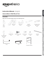 3
3
-
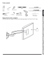 4
4
-
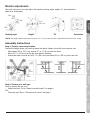 5
5
-
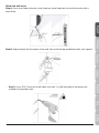 6
6
-
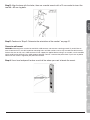 7
7
-
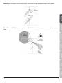 8
8
-
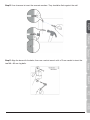 9
9
-
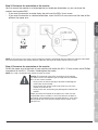 10
10
-
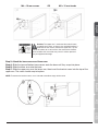 11
11
-
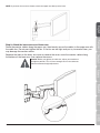 12
12
-
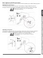 13
13
-
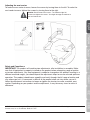 14
14
-
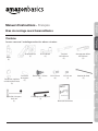 15
15
-
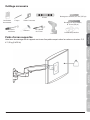 16
16
-
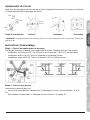 17
17
-
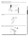 18
18
-
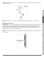 19
19
-
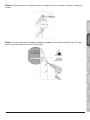 20
20
-
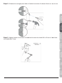 21
21
-
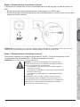 22
22
-
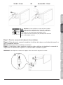 23
23
-
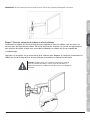 24
24
-
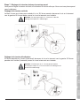 25
25
-
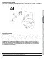 26
26
-
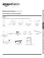 27
27
-
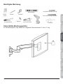 28
28
-
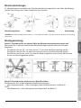 29
29
-
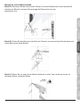 30
30
-
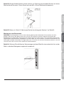 31
31
-
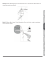 32
32
-
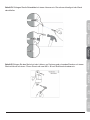 33
33
-
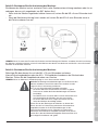 34
34
-
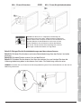 35
35
-
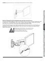 36
36
-
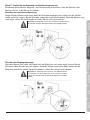 37
37
-
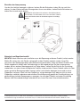 38
38
-
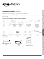 39
39
-
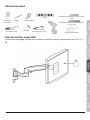 40
40
-
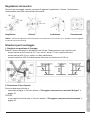 41
41
-
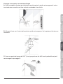 42
42
-
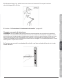 43
43
-
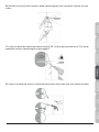 44
44
-
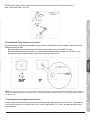 45
45
-
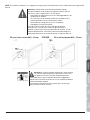 46
46
-
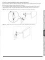 47
47
-
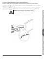 48
48
-
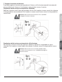 49
49
-
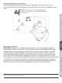 50
50
-
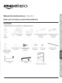 51
51
-
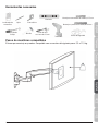 52
52
-
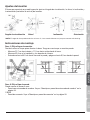 53
53
-
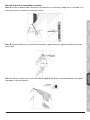 54
54
-
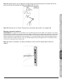 55
55
-
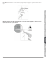 56
56
-
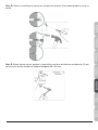 57
57
-
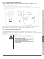 58
58
-
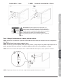 59
59
-
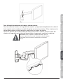 60
60
-
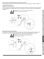 61
61
-
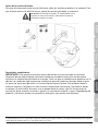 62
62
-
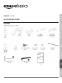 63
63
-
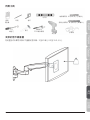 64
64
-
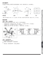 65
65
-
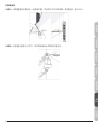 66
66
-
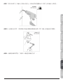 67
67
-
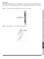 68
68
-
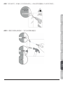 69
69
-
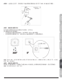 70
70
-
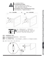 71
71
-
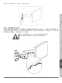 72
72
-
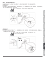 73
73
-
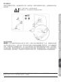 74
74
-
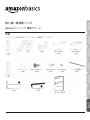 75
75
-
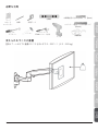 76
76
-
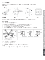 77
77
-
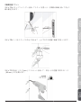 78
78
-
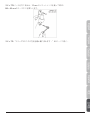 79
79
-
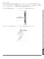 80
80
-
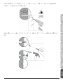 81
81
-
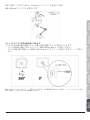 82
82
-
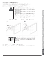 83
83
-
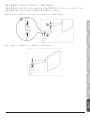 84
84
-
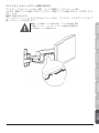 85
85
-
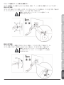 86
86
-
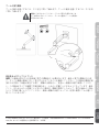 87
87
-
 88
88


Amazon B010QZCT5W Manual de usuario
- Categoría
- Soportes de pared para panel plano
- Tipo
- Manual de usuario
En otros idiomas
- français: Amazon B010QZCT5W Manuel utilisateur
- italiano: Amazon B010QZCT5W Manuale utente
- English: Amazon B010QZCT5W User manual
- Deutsch: Amazon B010QZCT5W Benutzerhandbuch
- 日本語: Amazon B010QZCT5W ユーザーマニュアル
Otros documentos
-
Amazon Basics Bras de support Simple à fixation Manual de usuario
-
 AmazonBasics K001504 Manual de usuario
-
AmazonBasics B01KBEOGZ4 Manual de usuario
-
König TVS-KN-FSB500 El manual del propietario
-
König TVS-KN-FSB110S Manual de usuario
-
 AmazonBasics PBH-994 Manual de usuario
-
PERLESMITH PSCLF Guía de instalación
-
-
 Bell'O Digital 7835B Guía del usuario
-
Epson ELPMB24 Wall Mount for the PowerLite 410W Manual de usuario


