El ATEN US3344I es un switch industrial USB 3.1 Gen 1 de 4 puertos que permite a los usuarios compartir dispositivos USB entre cuatro ordenadores. Es ideal para entornos industriales y comerciales donde se requiere una conectividad y fiabilidad robustas. El US3344I cuenta con una carcasa metálica resistente, puertos USB 3.1 Gen 1 con velocidades de transferencia de datos de hasta 5 Gbps y soporte para conexiones RS-422/RS-485. También incluye un selector de puerto remoto para una fácil selección de dispositivos y un kit de montaje para una instalación flexible.
El ATEN US3344I es un switch industrial USB 3.1 Gen 1 de 4 puertos que permite a los usuarios compartir dispositivos USB entre cuatro ordenadores. Es ideal para entornos industriales y comerciales donde se requiere una conectividad y fiabilidad robustas. El US3344I cuenta con una carcasa metálica resistente, puertos USB 3.1 Gen 1 con velocidades de transferencia de datos de hasta 5 Gbps y soporte para conexiones RS-422/RS-485. También incluye un selector de puerto remoto para una fácil selección de dispositivos y un kit de montaje para una instalación flexible.

Transcripción de documentos
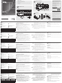
Package Contents B 1 4x4 USB 3.1 Gen 1 Industrial Hub Switch 2 USB 3.1 Gen 1 Type-B to Type-A Cable 1.2M 2 USB 3.1 Gen 1 Type-B to Type-A Cable 1.8M 1 Remote Port Selector 1 Mounting Kit 1 Terminal Block Adapter Set (an RS-422/RS-485 and a DC terminal block adapter) 1 User Instructions Support and Documentation Notice Hardware Installation All information, documentation, firmware, software utilities, and specifications contained in this package are subject to change without prior notification by the manufacturer. To reduce the environmental impact of our products, ATEN documentation and software can be found online at http://www.aten.com/download/ 2 Front A Technical Support Hardware Review www.aten.com/support Rear 5 Scan for more information 3 Front View 4 1 RS-422/RS485 US3344I EMC Information 4x4 USB 3.1 Gen 1 Industrial Hub Switch Quick Start Guide 1 Rear View 2 3 Mounting 8 © Copyright 2018 ATEN® International Co., Ltd. 4 ATEN and the ATEN logo are trademarks of ATEN International Co., Ltd. All rights reserved. All 5 6 7 9 other trademarks are the property of their respective owners. Part No. PAPE-1223-N70G C FEDERAL COMMUNICATIONS COMMISSION INTERFERENCE STATEMENT: This equipment has been tested and found to comply with the limits for a Class A digital device, pursuant to Part 15 of the FCC Rules. These limits are designed to provide reasonable protection against harmful interference when the equipment is operated in a commercial environment. This equipment generates, uses, and can radiate radio frequency energy and, if not installed and used in accordance with the instruction manual, may cause harmful interference to radio communications. Operation of this equipment in a residential area is likely to cause harmful interference in which case the user will be required to correct the interference at his own expense. FCC Caution: Any changes or modifications not expressly approved by the party responsible for compliance could void the user's authority to operate this equipment. Warning: Operation of this equipment in a residential environment could cause radio interference. 10 This device complies with Part 15 of the FCC Rules. Operation is subject to the following two conditions: (1) this device may not cause harmful interference, and (2) this device must accept any interference received, including interference that may cause undesired operation. Printing Date: 07/2018 이 기기는 업무용(A급) 전자파적합기기로서 판매자 또는 사용자는 이 점을 주의하시기 바라며, 가정외의 지역에 서 사용하는 것을 목적으로 합니다. US3344I 4x4 USB 3.1 Gen 1 Industrial Hub Switch A www.aten.com Hardware Review For RS-422 connection, the T +/- terminals of your selector system must be connected to the R +/- of the terminal block, and vice versa (e.g. T+ to R+, T- to R-). Front view 1 USB Type-A Peripheral Port 2 Port Indicator LEDs 3 RS-422/RS-485 LEDs Rear view 4 5 6 7 8 RS-422/RS-485 Serial Command Power Input (DC Jack) Power Input (DC Terminal Block) Remote Selector Jack Control DIP Switch Input (Terminal Block) 9 USB Type-B Host Port 10 Remote Port Selector Pin 1 2 3 RS-422 (4-wire) GND TxD - (A) TxD + (B) RS-485 (2-wire) GND - 4 5 RxD + (B) RxD - (A) Data + (A) Data – (B) B Hardware Installation Refer to the installation diagram above and do the following: 1 Plug the USB 3.1 Gen 1 Type-A end of the included USB cables into your computers (up to 4 computers) and plug the USB 3.1 Gen 1 Type-B end of the included USB cables into the back of the US3344I. 2 Plug your USB peripheral devices into the USB type-A peripheral ports of the US3344I. 3 Plug the Remote Port Selector to the Remote Selector Jack. 4 (Optional) Preparing RS-422/RS-485 Serial Command Port Selector: a. Select a port selection serial signal (RS-422/RS-485) from the DIP Switch on the back side of US3344I. b. Select serial terminal function from the DIP Switch on the back side of US3344I. c. Insert the command wires to the RS-422/RS-485 terminal block adapter according to the labeled sign of the chassis. Tighten the slot screws. Plug the terminal block adapter to the Serial Command Port. Note: 1. You can connect both Remote Port Selector and Serial Command Port Selectors for port selection. 2. For RS-422 connection, the T +/- terminals of your selector system must be connected to the R +/- terminals of the terminal block, and vice versa (e.g. T+ to R+, T- to R-). 5 Prepare a power input by either: a. Connecting the DC Terminal Block for Power Input1: Insert DC + and wires (9 to 24V DC) to the DC terminal block adapter according to the labeled sign. Tighten the slot screws. Plug the terminal block adapter to US3344I; Or b. (Optional) Connecting a power adapter2 to the DC power input jack. Note: 1. If both power inputs are connected, power from the DC jack will be C Mounting Use the screws provided with the mounting kit to screw the mounting bracket to the bottom of the unit (Refer to the drawings shown above). Rack Mounting Screw the mounting bracket to any convenient location on the rack. Wall Mounting Use the mounting bracket’s center screw hole to mount the unit on a wall. prioritized. 2. Available for purchase separately from your closest ATEN dealer (Part No.: 0AD8-8012-33MG) Commutateur industriel Gen 1 USB 3.1 à 4 ports US3344I A www.aten.com Présentation du matériel Pour la connexion RS-422, les bornes T +/- de votre système de sélecteur doivent être connectées aux bornes R +/- du bornier, et vice versa (par exemple T+ à R+, T- à R-). Vue de face 1 Port périphérique USB Type A 2 LED d'indicateur de port 3 LED RS-422/RS-485 Vue arrière 4 5 6 7 Entrée d'alimentation (Prise CC) Entrée d'alimentation (Bornier CC) Prise de sélecteur distant Commutateur DIP de commande 8 Entrée de commande série RS-422/RS-485 (Bornier) 9 Port hôte USB Type B 10 Sélecteur de port distant Broche 1 2 3 RS-422 (4 fils) GND TxD - (A) TxD + (B) RS-485 (2 fils) GND - 4 5 RxD + (B) RxD - (A) Données + (A) Données – (B) B Installation matérielle Consultez le schéma d'installation ci-dessus et procédez comme suit : 1 Branchez l'extrémité USB 3.1 Gen 1 Type A des câbles USB inclus dans vos ordinateurs (jusqu'à 4 ordinateurs) et branchez l'extrémité USB 3.1 Gen 1 Type B des câbles USB inclus à l'arrière de l'US3344I. 2 Branchez vos périphériques USB dans les ports périphériques USB Type A de l'US3344I. 3 Branchez le sélecteur de port distant à la prise de sélecteur distant. 4 (Facultatif) Préparation du sélecteur de port de commande série RS-422/RS-485 : a. Sélectionnez un signal série de sélection de port (RS-422/RS-485) à partir du commutateur DIP à l'arrière de l'US3344I. b. Sélectionnez la fonction de terminal série à partir du commutateur DIP à l'arrière de l'US3344I. c. Insérez les fils de commande dans l'adaptateur du bornier RS-422/ RS-485 selon le signe étiqueté du châssis. Serrez les vis à fente. Branchez l'adaptateur du bornier au port de commande série. Remarque : 1. Vous pouvez connecter le sélecteur de port distant et le sélecteur de port de commande série pour la sélection de port. 2. Pour la connexion RS-422, les bornes T +/- de votre système de sélecteur doivent être connectées aux bornes R +/- du bornier, et vice versa (par exemple T+ à R+, T- à R-). 5 Préparer une entrée d'alimentation de l'une ou l'autre des manières : a. Raccordement du bornier CC pour l'entrée d'alimentation1 : Insérez les fils CC + et - (9 à 24V CC) dans l'adaptateur du bornier CC selon le signe étiqueté. Serrez les vis à fente. Branchez l'adaptateur du bornier à l'US3344I; ou b. (Facultatif) Raccordement d'un adaptateur d'alimentation 2 à la prise d'entrée d'alimentation CC. Remarque : 1. Si les deux entrées d'alimentation sont connectées, C Montage Utilisez les vis fournies avec le kit de montage pour visser le support de montage au bas de l'appareil (Reportez-vous aux dessins ci-dessus). Montage en rack Vissez le support de montage dans un quelconque emplacement pratique sur le rack. Montage mural Utilisez le trou de vis central du support de montage pour monter l'appareil sur un mur. l'alimentation provenant de la prise CC sera prioritaire. 2. Disponible à l'achat séparément chez votre revendeur ATEN le plus proche (Référence : 0AD8-8012-33MG) US3344I 4-Port USB 3.1 Gen 1 Industrie Switch A www.aten.com Hardware Übersicht Für den RS-422-Anschluss müssen die T +/- Klemmen Ihres Auswahlsystems mit den R +/- Klemmen des Anschlussblocks verbunden werden und umgekehrt (z.B. T+ nach R+, T- nach R-). Ansicht von vorne 1 USB Typ-A Peripherie-Port 2 Port Anzeige-LEDs 3 RS-422/RS-485 LEDs Ansicht von hinten 4 5 6 7 Stromeingang (DC-Buchse) Stromeingang (DC-Anschlussblock) Remote Auswahlbuchse Steuerung DIP-Schalter 8 RS-422/RS-485 Serial Command Eingang (Anschlussblock) 9 USB Typ-B Host Port 10 Remote-Port-Wähler Pin 1 2 3 RS-422 (4-Draht) GND TxD - (A) TxD + (B) RS-485 (2-Draht) GND - 4 5 RxD + (B) RxD - (A) Daten + (A) Daten – (B) B Hardwareinstallation Halten Sie sich an die obige Installationsabbildung und gehen Sie wie folgt vor: 1 Schließen Sie das USB 3.1 Gen 1 Typ-A Ende der mitgelieferten USB-Kabel in Ihre Computer (bis zu 4 Computer) und das USB 3.1 Gen 1 Typ-B Ende der mitgelieferten USB-Kabel an der Rückseite des US3344I an. 2 Schließen Sie Ihre USB-Peripheriegeräte an die USB-A Peripherieanschlüsse des US3344I an. 3 Schließen Sie den Remote-Port-Wähler an die Remote Auswahlbuchse an. 4 (Optional) Vorbereitung des RS-422/RS-485 Serial Command Port Wählers: a. Wählen Sie ein Port Auswahl serielles Signal (RS-422/RS-485) über den DIP-Schalter an der Rückseite des US3344I. b. Wählen Sie die Funktion des seriellen Terminals über den DIP-Schalter an der Rückseite des US3344I. c. Fügen Sie die Steuerleitungen in den RS-422/RS-485 Anschlussblockadapter entsprechend dem beschrifteten Schild des Gehäuses ein. Ziehen Sie die Schlitzschrauben an. Schließen Sie den Anschlussblockadapter an den seriellen Befehlsanschluss an. Hinweis: 1. Sie können sowohl Remote-Port-Wähler als auch Serial Command Port Wähler zur Portauswahl anschließen. 2. Für den RS-422-Anschluss müssen die T +/- Klemmen Ihres Auswahlsystems mit den R +/- Klemmen des Anschlussblocks verbunden werden und umgekehrt (z.B. T+ nach R+, T- nach R-). 5 Bereiten Sie einen Stromeingang vor, indem Sie: a. Den DC-Anschluss für die Spannungsversorgung anschließen1: Schließen Sie die DC + und - Drähte (9 bis 24V DC) entsprechend dem beschrifteten Vorzeichen an den DC-Anschlussblockadapter an. Ziehen Sie die Schlitzschrauben an. Schließen Sie den Anschlussblockadapter an den US3344I an; oder b. (Optional) Anschluss eines Netzteils2 an die DC-Eingangsbuchse. Hinweis: 1. Wenn beide Stromeingänge angeschlossen sind, wird die C Montage Verwenden Sie die mit dem Montageset gelieferten Schrauben, um die Montagehalterung an der Unterseite des Geräts zu befestigen (siehe Zeichnungen oben). Rack-Montage Befestigen Sie die Montagehalterung mittels Schrauben an einer geeigneten Stelle im Rack. Wandmontage Verwenden Sie die mittlere Schraubenbohrung der Montagehalterung, um das Gerät an einer Wand zu befestigen. Stromversorgung über die DC-Buchse priorisiert. 2. Separat erhältlich bei Ihrem nächsten ATEN Händler (Artikelnr.: 0AD8-8012-33MG) US3344I Conmutador industrial de 4 puertos USB 3.1 Gen 1 A Revisión del hardware Para la conexión RS-422, los terminales T +/- de su sistema selector deben conectarse a los terminales R +/- del bloque de terminales y viceversa (por ejemplo, T + a R +, T- a R-). Vista frontal 3 LEDs RS-422/RS-485 1 Puerto Periférico USB tipo A 2 LEDs indicadores de puertos Vista posterior 4 Entrada de energía (clavija DC) 5 Entrada de alimentación (bloque de terminales DC) 6 Clavija de selección remota 7 Interruptor DIP de control www.aten.com 8 Entrada de comandos en serie RS-422/RS-485 (bloque de terminales) 9 Puerto host USB tipo B 10 Selector de puertos remotos Contacto 1 2 3 RS-422 (4 cables) GND TxD - (A) TxD + (B) RS-485 (2 cables) GND - 4 5 RxD + (B) RxD - (A) Datos + (A) Datos – (B) B Instalación de hardware Consulte el diagrama de instalación anterior y haga lo siguiente: 1 Enchufe el extremo del USB 3.1 Gen 1 tipo A de los cables USB incluidos en su ordenadores (hasta 4 ordenadores) y enchufe el extremo del USB 3.1 Gen 1 tipo B de los cables USB incluidos en la parte posterior del US3344I. 2 Conecte sus dispositivos periféricos USB a los puertos periféricos USB tipo A del US3344I. 3 Enchufe el Selector de puertos remotos a la Clavija del selector remoto. 4 (Opcional) Preparación del selector de puerto de comandos en serie RS-422/ RS-485: a. Seleccione una señal serie de selección de puertos (RS-422/RS-485) en el interruptor DIP de la parte posterior del US3344I. b. Seleccione la función del terminal serie en el interruptor DIP de la parte posterior del US3344I. c. Inserte los cables de comandos en el adaptador del bloque de terminales RS-422/RS-485 siguiendo las indicaciones de la etiqueta del chasis. Apriete los tornillos de la ranura. Enchufe el adaptador del bloque de terminales al puerto de comandos en serie. Nota: 1. Puede conectar el selector de puertos remotos y los selectores de puertos de comandos en serie para la selección del puerto. 2. Para la conexión RS-422, los terminales T +/- de su sistema selector deben conectarse a los terminales R +/- del bloque de terminales y viceversa (por ejemplo, T + a R +, T- a R-). 5 Prepare una entrada de energía: a. Conectando el bloque de terminales de CC para la entrada de alimentación1: Inserte los cables CC + y - (9 a 24V CC) en el adaptador del bloque de terminales de CC siguiendo las indicaciones de la etiqueta. Apriete los tornillos de la ranura. Conecte el adaptador del bloque de terminales al US3344I; O b. (Opcional) Conectando un adaptador de alimentación2 a la clavija de entrada de alimentación de CC. Nota: 1. Si ambas entradas de alimentación están conectadas, se dará prioridad C Montaje Utilice los tornillos provistos con el kit de montaje para atornillar el soporte de montaje a la parte inferior de la unidad (consulte los dibujos que se muestran arriba). Montaje en rack Atornille el soporte de montaje a cualquier parte del bastidor. Montaje en pared Utilice el orificio de tornillo central del soporte de montaje para montar la unidad en una pared. a la alimentación de la clavija de CC. 2. Disponible para su compra por separado en su distribuidor ATEN más cercano (Parte Nº: 0AD8-8012-33MG) Interruttore industriale US3344I USB 3.1 Gen 1 a 4 porte A www.aten.com Recensione hardware Per il collegamento RS-422, i terminali T +/- del sistema selettore devono essere collegati ai terminali R +/- della morsettiera e viceversa (ad es. da T+ a R+, da T- a R-). Vista anteriore 3 RS-422/RS-485 LED 1 Porta periferica USB tipo A 2 LED di segnalazione della porta Vista posteriore 4 Ingresso alimentazione (presa CC) 5 Ingresso di alimentazione 8 RS-422/RS-485 Ingresso comando (morsettiera CC) 6 Presa selettore remoto 7 Interruttore DIP di controllo 9 Porta host USB tipo B 10 Selettore remoto della porta seriale (morsettiera) Pin 1 2 3 RS-422 (4-fili) GND TxD - (A) TxD + (B) RS-485 (2-fili) GND - 4 5 RxD + (B) RxD - (A) Data + (A) Data – (B) B Installazione dell'hardware Fare riferimento allo scherma di installazione indicato sopra ed eseguire questi passaggi: 1 Collegare l'estremità USB 3.1 Gen 1 Type-A dei cavi USB in dotazione al computer (fino a 4 computer) e collegare l'estremità USB 3.1 Gen 1 Tipo-B dei cavi USB in dotazione al retro dell'US3344I. 2 Collegare i dispositivi periferici USB alle porte periferiche USB di tipo A dell'US3344I. 3 Collegare il selettore della porta remota alla presa del selettore remoto. 4 (Opzionale) Preparazione del selettore della porta di comando seriale RS-422/ RS-485: a. Selezionare un segnale seriale di selezione della porta (RS-422/RS-485) dal commutatore DIP sul retro di US3344I. b. Selezionare la funzione di terminale seriale dal commutatore DIP sul retro di US3344I. c. Inserire i fili di comando nell'adattatore della morsettiera RS-422/RS-485 in base al contrassegno sul telaio. Serrare a fondo le viti con intaglio. Collegare l'adattatore della morsettiera alla porta seriale di comando. Nota: 1. È possibile collegare sia il selettore di porte remote che i selettori di porte a comando seriale per la selezione delle porte. 2. Per il collegamento RS-422, i terminali T +/- del sistema selettore devono essere collegati ai terminali R +/- della morsettiera e viceversa (ad es. da T+ a R+, da T- a R-). 5 Preparare un ingresso di alimentazione da uno dei due: a. Collegamento della morsettiera CC per l'ingresso di alimentazione1: Inserire i fili + e - CC (da 9 a 24 V CC) nell'adattatore per morsettiera CC in base al contrassegno riportato sulla targhetta. Serrare a fondo le viti con intaglio. Collegare l'adattatore della morsettiera a US3344I; oppure b. (Opzionale) Collegamento di un adattatore di alimentazione2 al jack di ingresso dell'alimentazione CC. Nota: 1. Se sono collegati entrambi gli ingressi di alimentazione, viene data la C Montaggio Utilizzare le viti fornite con il kit di montaggio per avvitare la staffa di montaggio sul fondo dell'unità (fare riferimento ai disegni illustrati sopra). Montaggio in rack Avvitare la staffa di montaggio in qualsiasi posizione comoda sul rack. Montaggio a parete Utilizzare il foro della vite centrale della staffa di montaggio per montare l'unità su una parete. priorità all'alimentazione proveniente dalla presa CC. 2. Disponibile per l'acquisto separatamente dal rivenditore ATEN più vicino (codice articolo): 0AD8-8012-33MG) Промышленный коммутатор US3344I с 4 портами USB 3.1 (1 покол.) A Обзор аппаратной Вид спереди части 1 Периферийные порты USB (тип A) 2 Индикаторы портов При подключении порта RS-422 следует подсоединить контакты «T +/-» системы выбора порта к контактам «R +/-» на клеммной колодке (т.е. «T+» к «R+», «T-» к «R-»), и наоборот. 3 Индикаторы RS-422/RS-485 Вид сзади 4 5 6 7 8 Вход питания (гнездо пост.тока) Вход питания (клеммник пост.тока) 9 Гнездо селектора ДУ Управляющий DIP-переключатель 10 Выводы 1 2 3 4 5 Последовательный командный вход (клеммник) RS-422/RS-485 Порты USB (типа B) для хосткомпьютеров Селектор порта ДУ Порт RS-422 (4-проводной) GND TxD- (A) TxD+ (B) RxD+ (B) RxD - (A) www.aten.com Порт RS-485 (2-проводной) GND Данные+ (A) Данные- (B) B Установка оборудования Руководствуясь вышеприведенной монтажной схемой, выполните следующие действия: 1 Подключите разъемы USB 3.1 (тип A, 1 пок.) прилагаемых USBкабелей к компьютерам (до 4 компьютеров), а разъемы USB 3.1 (тип B, 1 пок.) — к портам на задней панели US3344I. 2 Подключите периферийные USB-устройства к периферийным портам USB (тип A) на коммутаторе US3344I. 3 Вставьте селектор порта ДУ в гнездо SELECTOR (Селектор ДУ). 4 (Дополнительно) Подготовка селектора последовательного командного порта RS-422/RS-485: a. Выберите последовательный сигнальный порт (RS-422/RS-485) с помощью DIP-переключателя на задней панели US3344I. b. Выберите функцию последовательного порта с помощью DIP-переключателя на задней панели US3344I. Примечание. 1. Если одновременно подключены оба входа питания, c. Вставьте провода командного интерфейса в клеммный адаптер RS-422/RS-485 в соответствии с маркировкой на корпусе. Затяните фиксирующие винты. Подсоедините клеммный адаптер RS-422/ RS-485 к последовательному командному порту Примечание. 1. Для выбора порта можно использовать как селектор порта ДУ, так и селектор последовательного командного порта. 2. При подключении порта RS-422 следует подсоединить контакты «T +/-» системы выбора порта к контактам «R +/-» на клеммной колодке (т.е. «T+» к «R+», «T-» к «R-»), и наоборот. 5 Подключите входное питание одним из следующих способов: a. Подключение клеммника пост.тока ко входу питания1: Подключите провода «+» и «-» от источника питания (9В–24В пост.тока) к контактам «+» и «-» на клеммном адаптере пост.тока в соответствии с маркировкой. Затяните фиксирующие винты. Подсоедините клеммный адаптер к US3344I; либо b. (Дополнительно) Подключение адаптера питания2 к входному гнезду питания пост.тока. приоритет будет иметь гнездо питания пост.тока. 2. Можно приобрести отдельно у ближайшего дилера ATEN (Номер изделия: 0AD8-8012-33MG) C Крепление Винтами из монтажного комплекта прикрепите монтажный кронштейн к нижней части устройства (как показано на схеме ниже). Монтаж в стойке Прикрепите монтажный кронштейн в стойку в любом удобном положении. Монтаж на стене Для монтажа блока станции на стену используйте центральное отверстие для болта в монтажном кронштейне.-
 1
1
-
 2
2


ATEN US3344I Guía de inicio rápido
- Tipo
- Guía de inicio rápido
- Este manual también es adecuado para
El ATEN US3344I es un switch industrial USB 3.1 Gen 1 de 4 puertos que permite a los usuarios compartir dispositivos USB entre cuatro ordenadores. Es ideal para entornos industriales y comerciales donde se requiere una conectividad y fiabilidad robustas. El US3344I cuenta con una carcasa metálica resistente, puertos USB 3.1 Gen 1 con velocidades de transferencia de datos de hasta 5 Gbps y soporte para conexiones RS-422/RS-485. También incluye un selector de puerto remoto para una fácil selección de dispositivos y un kit de montaje para una instalación flexible.
en otros idiomas
- français: ATEN US3344I Guide de démarrage rapide
- italiano: ATEN US3344I Guida Rapida
- English: ATEN US3344I Quick start guide
- Deutsch: ATEN US3344I Schnellstartanleitung
- русский: ATEN US3344I Инструкция по началу работы
- português: ATEN US3344I Guia rápido
- polski: ATEN US3344I Skrócona instrukcja obsługi
- 日本語: ATEN US3344I クイックスタートガイド
- Türkçe: ATEN US3344I Hızlı başlangıç Kılavuzu