ATEN VK2100 Guía de inicio rápido
- Categoría
- Componentes del dispositivo de seguridad
- Tipo
- Guía de inicio rápido

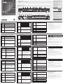
Hardware Overview and Connections
Connector /
LED
Connections
1.
Relay Channels
and LED
• 4 channels; normally open, isolated relays with a contact
rating of 24VDC, 2A max
• The LED lights green to indicate an active device
connection (closed loop).
2.
IR/Serial Ports
and LED
• 4 IR ports that can be also confi gured as RS-232 TX ports
• The LED lights green to indicate an active device
connection and IR signals are being transmitted.
3.
I/O Channels
and LED
• 4 channels that can be confi gured as digital inputs/
outputs;
digital input: 0-24VDC programmable input range or
contact closure with +12VDC pull-up; digital output:
250mA sink from 12VDC
• The LED lights green to indicate an active device
connection and I/O signals are being transmitted.
4.
Serial Ports
and LED
• RS-232 Ports : 2 ports with TX/RX functions supported
• RS-232/422/485 Ports: 4 ports with supported RS-
232/422/485 conversion by pin assignment, and RTS/CTS
fl ow control
• The LED (1~6) lights green to indicate serial signals are
being transmitted.
Aspectos generales del hardware y conexiones
Conector /
indicador LED
Conexiones
1.
Canales de relés y
LED
• 4 canales; normalmente abiertos, relés aislados con
tensión de contacto de 24 V c.c., máx. 2 A
• El indicador se ilumina de color verde cuando hay una
conexión con el dispositivo (circuito cerrado).
2.
Indicador LED de
infrarrojos/puertos
• 4 puertos de infrarrojos que también se pueden
confi gurar como puertos de transmisión RS-232
• El indicador se ilumina de color verde cuando hay una
conexión con el dispositivo y se transmiten las señales
infrarrojas.
3.
Canales de E/S y
LED
• 4 canales que se pueden confi gurar como entradas/
salidas digitales. Rango de entrada de 0 a 24V c.c.
o cierre de contactos programables con tensión
de reacción de 12 V c.c.; salida digital: Corriente
consumida de 250 mA sobre 12 V c.c.
• El indicador se ilumina de color verde cuando hay una
conexión con el dispositivo y se transmiten las señales
de E/S.
4. Puertos serie y LED
• Puertos RS-232: 2 puertos con funciones de
transmisión/recepción
• Puertos RS-232/422/485: 4 puertos con conversión
RS-232/422/485 por asignación de patillas y control
de fl ujo RTS/CTS
• Los indicadores LED (1 al 6) se iluminan de color verde
cuando se transmiten señales serie.
Panoramica hardware e funzionamento
Connettore / LED Connessioni
1. Canali relè e LED
• 4 canali: di solito aperti, relè isolati con valori nominali
di contatto di 24 VCC, 2A max
• Il LED si illumina di verde per indicare una connessione
attiva con un dispositivo (circuito chiuso).
2.
Porte a infrarossi/
seriali e LED
• 4 porte a infrarossi confi gurabili anche come porte RS-
232 TX
• Il LED si illumina di verde per indicare una connessione
attiva con un dispositivo e che vengono trasmessi i
segnali a infrarossi.
3. Canali I/O e LED
• 4 canali confi gurabili come ingressi/uscite digitali;
ingresso digitale: intervallo d’ingresso programmabile
0-24 VCC o chiusura contatto con una tensione di
pull-up di +12 VCC; uscita digitale: dissipazione 250
mA da 12 VCC
• Il LED si illumina di verde per indicare una connessione
attiva con un dispositivo e che vengono trasmessi i
segnali di I/O.
4. Porte seriali e LED
• Porte RS-232: 2 porte con supporto a funzioni TX/RX
• Porte RS-232/422/485: 4 porte con supporto alla
conversione RS-232/422/485 via assegnazione del pin
e controllo del fl usso RTS/CTS
• Il LED (1~6) si illumina di verde per indicare la
trasmissione dei segnali seriali.
Présentation du matériel et connexions
Connecteur /
LED
Connexions
1.
Canaux de
relais et LED
• 4 canaux ; relais normalement ouverts, isolés avec un
courant de régime des contacts de 24 VCC, 2 A max
• La LED s’allume en vert pour indiquer qu’une connexion de
périphérique est active (boucle fermée).
2.
Ports
infrarouges/
série et LED
• 4 ports infrarouges pouvant être confi gurés comme des
ports TX RS-232
• La LED s’allume en vert pour indiquer qu’une connexion de
périphérique est active et que des signaux infrarouges sont
en cours de transmission.
3.
Canaux d’E/S
et LED
• 4 canaux pouvant être confi gurés comme des entrées/
sorties numériques ;entrée numérique : plage d’entrée
programmable de 0 à 24 VCC ou fermeture des contacts
avec rappel vers le niveau haut de +12 VCC ; sortie
numérique : récepteur de 250 mA à partir de 12 VCC
• La LED s’allume en vert pour indiquer qu’une connexion de
périphérique est active et que des signaux d’E/S sont en
cours de transmission.
4.
Ports série et
LED
• Ports RS-232 : 2 ports avec prise en charge des fonctions
d’émission/réception
• Ports RS-232/422/485 : 4 ports avec prise en charge de la
conversion RS-232/422/485 par affectation des broches,
et contrôle de fl ux RTS/CTS
• La LED (1~6) s’allume en vert pour indiquer que les signaux
série sont en cours de transmission.
Hardwareübersicht und Anschlüsse
Anschluss/LED-Anzeige Anschlüsse
1. Relais-Kanäle und LED
• 4 Kanäle; normalerweise offen, isolierte Relais mit
schaltbaren 24 V= und max. 2 A
• Die LED-Anzeige leuchtet grün, wenn eine aktive
Geräteverbindung (geschlossener Kreis) besteht.
2.
Infrarot-/serielle Ports
und LED
• 4 Infrarotports, die auch als sendeseitige RS-232-
Ports konfi guriert werden können
• Die LED-Anzeige leuchtet grün, wenn eine aktive
Geräteverbindung besteht und die Infrarotsignale
übertragen werden.
3. E/A-Kanäle und LED
• 4 Kanäle, die als digitale Ein-/Ausgänge
konfi guriert werden können;
digitaler Eingang; programmierbarer
Eingagnsbereich von 0 bis 24 V= oder
Schließkontakt mit 12 V=; digitaler Ausgang:
250 mA Senke bei 12 V=
• Die LED-Anzeige leuchtet grün, wenn eine aktive
Geräteverbindung besteht und die E/A-Signale
übertragen werden.
4. Serielle Ports und LED
• RS-232-Ports: unterstützt 2 Ports für Sende-/
Empfangsfunktionen
• RS-232-/422-/485-Ports: unterstützt 4 Ports
mit RS-232-/422-/485-Umwandlung über
Stiftzuordnung und RTS-/CTS-Flusssteuerung
• Die LED-Anzeigen (1 bis 6) leuchten grün, wenn
serielle Daten übertragen werden.
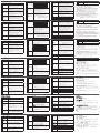
4.
Serial Ports
and LED
Pin Mapping
RS-232 RS-422 RS-485
Pin2: RX Pin1: RX- Pin3: D+
Pin3: TX Pin2: RX+ Pin4: D-
Pin5: GND Pin3: TX+
Pin7: RTS Pin4: TX-
Pin8: CTS Pin5: GND
5.
Ethernet Port
and LED
• This RJ-45 port can be used for network connection.
• If no IP is assigned within 30 seconds, the default IP
settings will be used:
IP: 192.168.0.60 / mask: 255.255.255.0
• LINK: The LED blinks green to indicate Ethernet signals are
being transmitted.
ACT: The LED lights green to indicate 100Mbps
transmissions.
6.
DC Outputs
and Overload
LED
• 4 outputs with a total power output of 24W at max
• The LED lights orange to indicate DC output exceeds
maximum output
Note: When the LED lights orange, please unplug any of
the connected devices to keep its total output under
24W.
4. Puertos serie y LED
Asignación de patillas
RS-232 RS-422 RS-485
Patilla 2: RX Patilla 1: RX- Patilla 3: D+
Patilla 3: TX Patilla 2: RX+ Patilla 4: D-
Patilla 5: GND Patilla 3: TX+
Patilla 7: RTS Patilla 4: TX-
Patilla 8: CTS Patilla 5: GND
5.
Puerto Ethernet y
LED
• Este puerto RJ-45 sirve para la conexión a la red
informática.
• Si dentro de los próximos 30 segundos no se asigna
ninguna IP, se utilizará la dirección IP predeterminada.
IP: 192.168.0.60 / subred: 255.255.255.0
• LINK: El indicador LED parpadea de color verde
cuando se transmiten señales Ethernet.
ACT: El indicador LED se ilumina en verde cuando se
transmiten señales a 100 Mbps.
6.
Salidas de c.c. y
LED de sobrecarga
• 4 salidas con una potencia máx. de 24 W
• El indicador LED se ilumina de color naranja cuando la
potencia de salida excede el valor máximo.
Nota: Si el indicador LED se ilumina de color naranja,
desconecte cualquiera de los dispositivos
conectados para reducir la potencia total de
salida por debajo de los 24 W.
4. Porte seriali e LED
Mappatura pin
RS-232 RS-422 RS-485
Pin2: RX Pin1: RX- Pin3: D+
Pin3: TX Pin2: RX+ Pin4: D-
Pin5: GND Pin3: TX+
Pin7: RTS Pin4: TX-
Pin8: CTS Pin5: GND
5.
Porta Ethernet e
LED
• Questa porta RJ-45 può essere usata per la
connessione di rete.
• Se non viene assegnato un IP entro 30 secondi,
verranno utilizzate le impostazioni IP predefi nite:
IP: 192.168.0.60 / maschera: 255.255.255.0
• LINK: Il LED si illumina di verde per indicare la
trasmissione dei segnali Ethernet.
ACT: Il LED si illumina di verde per indicare le
trasmissioni a 100 Mbps.
6.
Uscite CC e LED di
sovraccarico
• 4 uscite per una potenza totale in uscita di massimo
24 W
• Il LED si illumina di arancione per indicare che l’uscita
CC supera la potenza massima
Nota: quando il LED si illumina di arancione,
scollegare i dispositivi collegati per mantenere la
potenza totale al di sotto dei 24 W.
4.
Ports série et
LED
Mappage de broches
RS-232 RS-422 RS-485
Broche 2 : RX Broche 1 : RX- Broche 3 : D+
Broche 3 : TX Broche 2 : RX+ Broche 4 : D-
Broche 5 : GND
(terre)
Broche 3 : TX+
Broche 7 : RTS Broche 4 : TX-
Broche 8 : CTS Broche 5 : GND
(terre)
5.
Port Ethernet
et LED
• Ce port RJ-45 peut être utilisé pour la connexion réseau.
• Si aucune adresse IP n’est attribuée dans l’intervalle de 30
secondes, les paramètres IP par défaut sont utilisés :
IP : 192.168.0.60 / masque : 255.255.255.0
• LINK : cette LED clignote en vert pour indiquer que les
signaux Ethernet sont en cours de transmission.
• ACT : cette LED s’allume en vert pour indiquer que des
transmissions à 100 Mbits/s sont en cours.
6.
Sorties CC
et LED de
surcharge
• 4 sorties avec une puissance de sortie totale max. de 24 W
• La LED s’allume en orange pour indiquer que la puissance
de sortie CC dépasse la puissance de sortie maximale
Remarque : si cette LED s’allume en orange, débranchez
l’un des périphériques connectés pour
maintenir la puissance de sortie totale à
moins de 24 W.
4. Serielle Ports und LED
Stiftzuordnung
RS-232 RS-422 RS-485
Stift 2: RX Stift 1: RX- Stift 3: D+
Stift 3: TX Stift 2: RX+ Stift 4: D-
Stift 5: GND Stift 3: TX+
Stift 7: RTS Stift 4: TX-
Stift 8: CTS Stift 5: GND
5. Ethernet-Port und LED
• Dieser RJ-45-Port kann für die Verbindung zum
Netzwerk verwendet werden.
• Wird innerhalb der folgenden 30 Sekunden
keine IP-Adresse zugeordnet, werden die
voreingestellten IP-Einstellungen verwendet:
IP: 192.168.0.60 / Subnetzmaske: 255.255.255.0
• LINK: Die LED-Anzeige blinkt grün, wenn
Ethernet-Signale übertragen werden.
ACT: Die LED-Anzeige leuchtet grün, wenn eine
100 Mbps-Verbindung besteht.
6.
Gleichspannungsausgänge
und Überlastungs-LED
• 4 Ausgänge mit maximal 24 W Ausgangsleistung
• Die LED-Anzeige leuchtet orange, wenn der
Gleichspannungsausgang die maximal zulässige
Last überschreitet.
Hinweis: Wenn die LED-Anzeige orange leuchtet,
trennen Sie die Verbindung eines
beliebigen Gerätes, und stellen Sie
sicher, dass der Ausgang mit weniger als
24 W belastet wird.
7.
IR Receiver
and LED
• This IR receiver passes the functions of a remote control to
the VK2100 in learning mode. The distance between the
IR remote and the receiver window should be kept under
10cm with a direct line of sight.
• The LED blinks green to indicate the unit is ready to receive
signals from an IR remote control.
8
USB Port and
LED
• This is where a USB device plugs in to upload Viewer fi les
to the VK2100.
• The LED blinks green to indicate Viewer fi les are being
uploaded, and lights green to indicate a successful upload
of Viewer fi les.
• The LED lights orange to indicate Viewer fi les failed to
upload.
9. Reset Switch
This semi-recessed pushbutton can be pressed to reset the
VK2100’s network settings.
10.
Power Switch
and LED
• This standard rocker switch powers the unit on and off.
• The LED lights green when the unit is turned on.
11. Power Socket
This standard 3-pin AC power socket is where the power
cord plugs in.
12.
Grounding
Terminal
This is where the grounding wire attaches.
13.
Controller ID
Switch
This 16-segment switch is used for controller ID selection.
7.
Receptor de
infrarrojos y LED
de recepción
• Este receptor de infrarrojos retransmite las funciones
de un mando a distancia al VK2100 cuando este
se encuentre en modo de aprendizaje. El mando a
distancia y el sensor del receptor deben mantenerse
dentro de una distancia máxima de 10 cm y no debe
de haber obstáculos entre ellos.
• El indicador LED parpadea en color verde cuando la
unidad está lista para recibir señales de una mando a
distancia por infrarrojos.
8 Puerto USB y LED
• Aquí se conecta un dispositivo USB para subir archivos
del Visor al VK2100.
• El indicador LED parpadea cuando se estén subiendo
archivos con el Visor. Se ilumina de color verde cuando
los archivos del Visor hayan sido subidos con éxito.
• El indicador LED se ilumina de color naranja cuando no
se hayan podido subir los archivos del Visor.
9.
Interruptor de
reseteo
Puede pulsar este botón semiescondido para resetear
los ajustes de red del VK2100.
10.
Botón de
alimentación y LED
• Este interruptor basculante sirve para encender y
apagar la unidad.
• El indicador LED se ilumina de color verde cuando la
unidad está encendida.
11.
Entrada de
alimentación
A esta entrada de alimentación homologada de
3 conductores se tiene que conectar el cable de
alimentación.
12. Toma de tierra Aquí se conecta el cable de tierra.
7.
Ricevitore a
infrarossi e LED
• Questo ricevitore a infrarossi passa le funzioni del
telecomando al VK2100 in modalità apprendimento.
La distanza tra il telecomando e il sensore del ricevitore
deve essere inferiore ai 10 cm in linea retta.
• Il LED lampeggia in verde per indicare che l’unità è
pronta a ricevere i segnali dal telecomando a infrarossi.
8 Porte USB e LED
• Qui è possibile collegare un dispositivo USB per
caricare i fi le del visualizzatore sul VK2100.
• Il LED lampeggia in verde per indicare che i fi le del
visualizzatore sono in caricamento e si illumina in
verde per indicare che il caricamento è riuscito.
• Il LED si illumina in arancione per indicare che il
caricamento dei fi le del visualizzatore non è riuscito.
9.
Interruttore di
ripristino
Questo pulsante semi-incassato va premuto per
ripristinare le impostazioni di rete del VK2100.
10.
Interruttore di
alimentazione e
LED
• Questo interruttore Rocker standard accende e spegne
l’unità.
• Il LED si illumina in verde quando l’unità è accesa.
11.
Presa per
l’alimentazione
A questa presa di alimentazione CA standard a 3 pin va
collegato il cavo di alimentazione.
12.
Terminale di messa
a terra
Qui si collega il fi lo di messa a terra.
13.
Interruttore dell’ID
del controller
Questo interruttore a 16 segmenti è utilizzato per
selezionare l’ID del controller.
7.
Récepteur
infrarouge et
LED
• Ce récepteur infrarouge transmet les fonctions de
télécommande au VK2100 en mode d’apprentissage. La
distance entre la télécommande infrarouge et la fenêtre de
récepteur doit toujours être inférieure à 10 cm avec une
ligne de vue directe.
• La LED clignote en vert pour indiquer que l’unité est prête
à recevoir les signaux de la télécommande infrarouge.
8
Port USB et
LED
• Ce port sert à la connexion d’un périphérique USB pour le
chargement des fi chiers de la visionneuse (Viewer) vers le
VK2100.
• Cette LED clignote en vert pour indiquer que les fi chiers de
la visionneuse sont en cours de chargement ; elle s’allume
en vert pour indiquer que le chargement des fi chiers de la
visionneuse s’est correctement effectué.
• Cette LED s’allume en orange pour indiquer que le
chargement des fi chiers de la visionneuse a échoué.
9.
Bouton de
réinitialisation
Ce bouton-poussoir semi-encastré permet de réinitialiser les
paramètres réseau du VK2100.
10.
Bouton
marche/arrêt
et LED
• Cet interrupteur à bascule standard allume et éteint l’unité.
• La LED s’allume en vert lorsque l’unité est mise en marche.
11.
Prise
d'alimentation
Le cordon d’alimentation se branche sur cette prise
d’alimentation CA standard à 3 broches.
12. Prise de terre Cette prise sert au raccordement du fi l de terre.
7.
Infrarot-Empfänger und
LED
• Dieser Infrarot-Empfänger leitet die Funktionen
einer Fernbedienung im Lernmodus an den
VK2100 weiter. Die Entfernung zwischen der
Fernbedienung und dem Sensor sollte maximal
10 cm betragen, und dazwischen sollten sich
keine Hindernisse befi nden.
• Die LED-Anzeige blinkt grün, wenn das Gerät zum
Empfang von Infrarotsignalen bereit ist.
8 USB-Port und LED
• Hier schließen Sie ein USB-Gerät an, um Viewer-
Dateien auf den VK2100 hochzuladen.
• Die LED-Anzeige blinkt grün, wenn Viewer-
Dateien hochgeladen werden. Sie leuchtet grün,
wenn die Viewer-Dateien erfolgreich hochgeladen
worden sind.
• Die LED-Anzeige leuchtet orange, wenn die
Aktualisierung der Viewer-Dateien fehlgeschlagen
ist.
9.
Schalter zum
Zurücksetzen
Drucken Sie die halbverdeckte Drucktaste, um die
Netzwerkeinstellungen des VK2100 zurückzusetzen.
10.
Ein-/Aus-Schalter und
LED
• Dieser Kippschalter schaltet das Gerät ein bzw.
aus.
• Die LED-Anzeige leuchtet grün, wenn das Gerät
eingeschaltet ist.
11. Netzeingangsbuchse
An diese 3-polige Kaltgerätebuchse schließen Sie
das Netzkabel an.
12. Erdungsanschluss Hier schließen Sie den Erdleiter an.
System Setup
Step 1. Connect Hardware
Please complete hardware connections as instructed in the table above.
Step 2. Install Software
• Please install VK6000 and Database Generator (optional) from the software CD
that comes in the package.
• From the VK6000, create and design your own project profi le and control GUI
based on the scale of your environment and hardware requirements.
Step 3. Download App on Viewer
From a viewer (i.e. Apple iPad series), download and install the ATEN Control
System App. Connect the APP to the VK2100 via LAN connection to import your
pre-confi gured project profi le. Once complete, you may start to control and
manage all connected hardware devices in the room.
Note: Please refer to the VK2100/VK6000 user manual for more details about
software and hardware setup.
13.
Conmutador del
ID del Controller
Este conmutador sirve para seleccionar el ID del
controller.
Confi gurar el sistema
Paso 1: Conectar el hardware
Realice la conexión del hardware según las instrucciones de la tabla anterior.
Paso 2: Instalar el software
• Instale el software del VK6000 y el Database Generator (opcional) del CD de
software incluido.
• Desde el VK6000, cree y diseñe su perfi l de proyecto individual y controle la
interfaz de usuario en base a los requisitos de su plataforma y hardware.
Paso 3: Descargar la App en el Visor
En un Visor (p.ej. un Apple iPad), descárguese e instale la App del ATEN Control
System. Conecte la App al VK2100 a través de una conexión LAN e importe su
perfi l de proyecto previamente confi gurado. Cuando haya terminado, podrá
controlar y administrar todos los dispositivos hardware conectados en el entorno.
Nota: Consulte el manual del VK2100/VK6000 para obtener información más
detallada sobre la confi guración del software y hardware.
Impostazione del sistema
Punto 1. Collegare l’hardware
Completare i collegamenti hardware come da istruzioni nella tabella precedente.
Punto 2. Installare il software
• Installare il software VK6000 e Database Generator (opzionale) dal CD software
incluso nella confezione.
• Con VK6000, creare e confi gurare il proprio profi lo di progetto e interfaccia di
controllo in base alle dimensioni dell’ambiente e ai requisiti hardware.
Punto 3. Scaricare l’app sul visualizzatore
Da un visualizzatore (per esempio un Apple iPad), scaricare e installare l’app
ATEN Control System. Collegare l’app al VK2100 via LAN per importare il profi lo
progetto preconfi gurato. Una volta completato, è possibile iniziare a controllare e
gestire tutti i dispositivi hardware connessi nella stanza.
Nota: consultare il manuale dell’utente del VK2100/VK6000 per ulteriori dettagli
sull’impostazione hardware e software.
13.
Commutateur
ID du
contrôleur
Ce commutateur à 16 segments est utilisé pour la sélection
de l’identifi ant du contrôleur.
Confi guration du système
Etape 1. Connexion du matériel
Réalisez les branchements de matériel conformément aux indications du tableau
ci-dessus.
Etape 2. Installation du logiciel
• Installez le logiciel VK6000 ainsi que le Database Generator (en option) à partir
du CD logiciel fourni.
• Depuis le VK6000, créez et confi gurez un profi l de projet et une interface de
commande personnalisés en fonction des exigences de votre environnement et
de votre matériel.
Etape 3. Téléchargement de l’application sur la visionneuse
Utilisez une visionneuse (un modèle de la gamme Apple iPad) pour télécharger et
installer l’application ATEN Control System. Connectez l’application au VK2100 via
une connexion réseau pour importer votre profi l de projet préconfi guré. Une fois
l’importation terminée, vous pouvez commencer à commander et à gérer tous les
dispositifs matériels connectés dans la pièce.
Remarque : Reportez-vous au manuel d’utilisation du VK2100/VK6000 pour en
savoir plus sur la confi guration logicielle et matérielle.
13.
Controller-ID-
Umschalter
Dieser Umschalter mit 16 Segmenten dient zur
Auswahl der Controller-ID.
System einrichten
Schritt 1: Hardware anschließen
Schließen Sie die Hardware anhand der Anweisungen der folgenden Tabelle an.
Schritt 2: Software installieren
• In stallieren Sie die VK6000-Software und den Database Generator (optional) von
der mitgelieferten Software-CD.
• Er stellen Sie über den VK6000 Ihr persönliches Projektprofi l und die
Benutzeroberfl äche für Ihre eigene Umgebungs- und Hardwareanforderungen.
Schritt 3: App auf den Viewer herunterladen
Downlo aden und installieren Sie die ATEN Control System App auf einem Viewer
(z.B. auf einem Apple iPad). Verbinden Sie die App über Ihr LAN mit dem VK2100,
und importieren Sie Ihr vorkonfiguriertes Projektprofil. Wenn Sie fertig sind,
können Sie alle in dieser Umgebung angemeldeten verbundenen Hardwaregeräte
steuern und verwalten.
Hinweis: Im Benutzerhandbuch zum VK2100/VK6000 fi nden Sie weitere Details
zur Hard- und Softwarekonfi guration.
Package Contents
1 VK2100 ATEN Controller
1 Mounting Kit
1 Power Cord
9 Terminal Blocks
1 User Instructions
© Copyright 2016 ATEN
®
International Co., Ltd.
ATEN and the ATEN logo are trademarks of ATEN International Co., Ltd. All rights reserved. All
other trademarks are the property of their respective owners.
This product is RoHS compliant.
Part No. PAPE-1223-D01G Printing Date: 06/2016
ATEN Controller
Quick Start Guide
VK2100
VK2100 ATEN Controller Quick Start Guide
www.aten.com
VK2100 ATEN Controller - Guide de démarrage rapide
www.aten.com
VK2100 ATEN Controller Kurzanleitung
www.aten.com
VK2100 ATEN Controller Guía rápida
www.aten.com
VK2100 ATEN Controller - Guida rapida
www.aten.com
ATEN VanCryst
™
9
10
5 6 7 81 2 3 4
12 6 1 2 411 10 3 5 13
Front View
Rear View
Support and Documentation Notice
All information, documentation, fi rmware,
software utilities, and specifi cations
contained in this package are subject to
change without prior notifi cation by
the manufacturer.
To reduce the environmental impact of our
products, ATEN documentation and software
can be found online at
http://www.aten.com/download/
Technical Support
www.aten.com/support
이 기기는 업무용(A급) 전자파적합기기로서 판매자 또는
사용자는 이 점을 주의하시기 바라며, 가정외의 지역에
서 사용하는 것을 목적으로 합니다.
EMC Information
FEDERAL COMMUNICATIONS COMMISSION INTERFERENCE STATEMENT:
This equipment has been tested and found to comply with the limits
for a Class A digital device, pursuant to Part 15 of the FCC Rules.
These limits are designed to provide reasonable protection against
harmful interference when the equipment is operated in a commercial
environment. This equipment generates, uses, and can radiate radio
frequency energy and, if not installed and used in accordance with
the instruction manual, may cause harmful interference to radio
communications. Operation of this equipment in a residential area
is likely to cause harmful interference in which case the user will be
required to correct the interference at his own expense.
FCC Caution: Any changes or modifi cations not expressly approved by
the party responsible for compliance could void the user's authority to
operate this equipment.
Warning: This equipment is compliant with Class A of CISPR 32. In a
residential environment this equipment may cause radio interference.
Suggestion: Shielded twisted pair (STP) cables must be used with the
unit to ensure compliance with FCC & CE standards.
This device complies with Part 15 of the FCC Rules. Operation is subject
to the following two conditions:(1) this device mat not cause harmful
interference, and(2) this device must accept any interference received,
including interference that may cause undesired operation.
Scan for
more information
Hardware Overview
La página se está cargando...
Transcripción de documentos
Package Contents Support and Documentation Notice 1 VK2100 ATEN Controller 1 Mounting Kit 1 Power Cord 9 Terminal Blocks 1 User Instructions All information, documentation, firmware, software utilities, and specifications contained in this package are subject to change without prior notification by the manufacturer. To reduce the environmental impact of our products, ATEN documentation and software can be found online at http://www.aten.com/download/ Hardware Overview Technical Support 1 Front View 2 3 4 5 6 7 8 9 www.aten.com/support 10 Scan for more information ATEN VanCryst™ VK2100 EMC Information ATEN Controller Quick Start Guide FEDERAL COMMUNICATIONS COMMISSION INTERFERENCE STATEMENT: This equipment has been tested and found to comply with the limits for a Class A digital device, pursuant to Part 15 of the FCC Rules. These limits are designed to provide reasonable protection against harmful interference when the equipment is operated in a commercial environment. This equipment generates, uses, and can radiate radio frequency energy and, if not installed and used in accordance with the instruction manual, may cause harmful interference to radio communications. Operation of this equipment in a residential area is likely to cause harmful interference in which case the user will be required to correct the interference at his own expense. FCC Caution: Any changes or modifications not expressly approved by the party responsible for compliance could void the user's authority to operate this equipment. Warning: This equipment is compliant with Class A of CISPR 32. In a residential environment this equipment may cause radio interference. Suggestion: Shielded twisted pair (STP) cables must be used with the unit to ensure compliance with FCC & CE standards. Rear View 12 11 10 6 1 2 3 4 5 13 © Copyright 2016 ATEN® International Co., Ltd. ATEN and the ATEN logo are trademarks of ATEN International Co., Ltd. All rights reserved. All other trademarks are the property of their respective owners. This device complies with Part 15 of the FCC Rules. Operation is subject to the following two conditions:(1) this device mat not cause harmful interference, and(2) this device must accept any interference received, including interference that may cause undesired operation. This product is RoHS compliant. Part No. PAPE-1223-D01G Printing Date: 06/2016 이 기기는 업무용(A급) 전자파적합기기로서 판매자 또는 사용자는 이 점을 주의하시기 바라며, 가정외의 지역에 서 사용하는 것을 목적으로 합니다. VK2100 ATEN Controller Quick Start Guide www.aten.com Hardware Overview and Connections Connector / LED Pin Mapping Connections • 4 channels; normally open, isolated relays with a contact Relay Channels rating of 24VDC, 2A max 1. and LED • The LED lights green to indicate an active device connection (closed loop). • 4 IR ports that can be also configured as RS-232 TX ports IR/Serial Ports 2. • The LED lights green to indicate an active device and LED connection and IR signals are being transmitted. • 4 channels that can be configured as digital inputs/ outputs; digital input: 0-24VDC programmable input range or I/O Channels 3. contact closure with +12VDC pull-up; digital output: and LED 250mA sink from 12VDC • The LED lights green to indicate an active device connection and I/O signals are being transmitted. • RS-232 Ports : 2 ports with TX/RX functions supported • RS-232/422/485 Ports: 4 ports with supported RSSerial Ports 232/422/485 conversion by pin assignment, and RTS/CTS 4. and LED flow control • The LED (1~6) lights green to indicate serial signals are being transmitted. 4. Serial Ports and LED RS-232 Pin2: RX Pin3: TX Pin5: GND Pin7: RTS Pin8: CTS RS-422 Pin1: RXPin2: RX+ Pin3: TX+ Pin4: TXPin5: GND RS-485 Pin3: D+ Pin4: D- • This RJ-45 port can be used for network connection. • If no IP is assigned within 30 seconds, the default IP settings will be used: Ethernet Port IP: 192.168.0.60 / mask: 255.255.255.0 5. and LED • LINK: The LED blinks green to indicate Ethernet signals are being transmitted. ACT: The LED lights green to indicate 100Mbps transmissions. • 4 outputs with a total power output of 24W at max • The LED lights orange to indicate DC output exceeds DC Outputs maximum output 6. and Overload Note: When the LED lights orange, please unplug any of LED the connected devices to keep its total output under 24W. 7. 8 9. 10. 11. 12. 13. • This IR receiver passes the functions of a remote control to the VK2100 in learning mode. The distance between the IR Receiver IR remote and the receiver window should be kept under and LED 10cm with a direct line of sight. • The LED blinks green to indicate the unit is ready to receive signals from an IR remote control. • This is where a USB device plugs in to upload Viewer files to the VK2100. • The LED blinks green to indicate Viewer files are being USB Port and uploaded, and lights green to indicate a successful upload LED of Viewer files. • The LED lights orange to indicate Viewer files failed to upload. This semi-recessed pushbutton can be pressed to reset the Reset Switch VK2100’s network settings. Power Switch • This standard rocker switch powers the unit on and off. and LED • The LED lights green when the unit is turned on. This standard 3-pin AC power socket is where the power Power Socket cord plugs in. Grounding This is where the grounding wire attaches. Terminal Controller ID This 16-segment switch is used for controller ID selection. Switch System Setup Step 1. Connect Hardware Please complete hardware connections as instructed in the table above. Step 2. Install Software • Please install VK6000 and Database Generator (optional) from the software CD that comes in the package. • From the VK6000, create and design your own project profile and control GUI based on the scale of your environment and hardware requirements. Step 3. Download App on Viewer From a viewer (i.e. Apple iPad series), download and install the ATEN Control System App. Connect the APP to the VK2100 via LAN connection to import your pre-configured project profile. Once complete, you may start to control and manage all connected hardware devices in the room. Note: Please refer to the VK2100/VK6000 user manual for more details about software and hardware setup. VK2100 ATEN Controller - Guide de démarrage rapide www.aten.com Présentation du matériel et connexions Connecteur / Connexions LED • 4 canaux ; relais normalement ouverts, isolés avec un Canaux de courant de régime des contacts de 24 VCC, 2 A max 1. • La LED s’allume en vert pour indiquer qu’une connexion de relais et LED périphérique est active (boucle fermée). • 4 ports infrarouges pouvant être configurés comme des Ports ports TX RS-232 2. infrarouges/ • La LED s’allume en vert pour indiquer qu’une connexion de périphérique est active et que des signaux infrarouges sont série et LED en cours de transmission. • 4 canaux pouvant être configurés comme des entrées/ sorties numériques ;entrée numérique : plage d’entrée programmable de 0 à 24 VCC ou fermeture des contacts Canaux d’E/S avec rappel vers le niveau haut de +12 VCC ; sortie 3. numérique : récepteur de 250 mA à partir de 12 VCC et LED • La LED s’allume en vert pour indiquer qu’une connexion de périphérique est active et que des signaux d’E/S sont en cours de transmission. • Ports RS-232 : 2 ports avec prise en charge des fonctions d’émission/réception Ports série et • Ports RS-232/422/485 : 4 ports avec prise en charge de la 4. conversion RS-232/422/485 par affectation des broches, LED et contrôle de flux RTS/CTS • La LED (1~6) s’allume en vert pour indiquer que les signaux série sont en cours de transmission. Mappage de broches Ports série et 4. LED 5. Port Ethernet et LED Sorties CC 6. et LED de surcharge RS-232 Broche 2 : RX Broche 3 : TX Broche 5 : GND (terre) Broche 7 : RTS Broche 8 : CTS RS-422 Broche 1 : RXBroche 2 : RX+ Broche 3 : TX+ RS-485 Broche 3 : D+ Broche 4 : D- 7. Broche 4 : TXBroche 5 : GND (terre) • Ce port RJ-45 peut être utilisé pour la connexion réseau. • Si aucune adresse IP n’est attribuée dans l’intervalle de 30 secondes, les paramètres IP par défaut sont utilisés : IP : 192.168.0.60 / masque : 255.255.255.0 • LINK : cette LED clignote en vert pour indiquer que les signaux Ethernet sont en cours de transmission. • ACT : cette LED s’allume en vert pour indiquer que des transmissions à 100 Mbits/s sont en cours. • 4 sorties avec une puissance de sortie totale max. de 24 W • La LED s’allume en orange pour indiquer que la puissance de sortie CC dépasse la puissance de sortie maximale Remarque : si cette LED s’allume en orange, débranchez l’un des périphériques connectés pour maintenir la puissance de sortie totale à moins de 24 W. 8 9. 10. 11. 12. • Ce récepteur infrarouge transmet les fonctions de télécommande au VK2100 en mode d’apprentissage. La Récepteur distance entre la télécommande infrarouge et la fenêtre de infrarouge et récepteur doit toujours être inférieure à 10 cm avec une LED ligne de vue directe. • La LED clignote en vert pour indiquer que l’unité est prête à recevoir les signaux de la télécommande infrarouge. • Ce port sert à la connexion d’un périphérique USB pour le chargement des fichiers de la visionneuse (Viewer) vers le VK2100. • Cette LED clignote en vert pour indiquer que les fichiers de Port USB et la visionneuse sont en cours de chargement ; elle s’allume LED en vert pour indiquer que le chargement des fichiers de la visionneuse s’est correctement effectué. • Cette LED s’allume en orange pour indiquer que le chargement des fichiers de la visionneuse a échoué. Bouton de Ce bouton-poussoir semi-encastré permet de réinitialiser les réinitialisation paramètres réseau du VK2100. Bouton • Cet interrupteur à bascule standard allume et éteint l’unité. marche/arrêt • La LED s’allume en vert lorsque l’unité est mise en marche. et LED Prise Le cordon d’alimentation se branche sur cette prise d'alimentation d’alimentation CA standard à 3 broches. Prise de terre Cette prise sert au raccordement du fil de terre. Commutateur Ce commutateur à 16 segments est utilisé pour la sélection 13. ID du de l’identifiant du contrôleur. contrôleur Configuration du système Etape 1. Connexion du matériel Réalisez les branchements de matériel conformément aux indications du tableau ci-dessus. Etape 2. Installation du logiciel • Installez le logiciel VK6000 ainsi que le Database Generator (en option) à partir du CD logiciel fourni. • Depuis le VK6000, créez et configurez un profil de projet et une interface de commande personnalisés en fonction des exigences de votre environnement et de votre matériel. Etape 3. Téléchargement de l’application sur la visionneuse Utilisez une visionneuse (un modèle de la gamme Apple iPad) pour télécharger et installer l’application ATEN Control System. Connectez l’application au VK2100 via une connexion réseau pour importer votre profil de projet préconfiguré. Une fois l’importation terminée, vous pouvez commencer à commander et à gérer tous les dispositifs matériels connectés dans la pièce. Remarque : Reportez-vous au manuel d’utilisation du VK2100/VK6000 pour en savoir plus sur la configuration logicielle et matérielle. www.aten.com VK2100 ATEN Controller Kurzanleitung Hardwareübersicht und Anschlüsse 1. 2. 3. 4. Anschluss/LED-Anzeige Anschlüsse • 4 Kanäle; normalerweise offen, isolierte Relais mit schaltbaren 24 V= und max. 2 A Relais-Kanäle und LED • Die LED-Anzeige leuchtet grün, wenn eine aktive Geräteverbindung (geschlossener Kreis) besteht. • 4 Infrarotports, die auch als sendeseitige RS-232Ports konfiguriert werden können Infrarot-/serielle Ports • Die LED-Anzeige leuchtet grün, wenn eine aktive und LED Geräteverbindung besteht und die Infrarotsignale übertragen werden. • 4 Kanäle, die als digitale Ein-/Ausgänge konfiguriert werden können; digitaler Eingang; programmierbarer Eingagnsbereich von 0 bis 24 V= oder E/A-Kanäle und LED Schließkontakt mit 12 V=; digitaler Ausgang: 250 mA Senke bei 12 V= • Die LED-Anzeige leuchtet grün, wenn eine aktive Geräteverbindung besteht und die E/A-Signale übertragen werden. • RS-232-Ports: unterstützt 2 Ports für Sende-/ Empfangsfunktionen • RS-232-/422-/485-Ports: unterstützt 4 Ports Serielle Ports und LED mit RS-232-/422-/485-Umwandlung über Stiftzuordnung und RTS-/CTS-Flusssteuerung • Die LED-Anzeigen (1 bis 6) leuchten grün, wenn serielle Daten übertragen werden. Stiftzuordnung 4. Serielle Ports und LED RS-232 Stift 2: RX Stift 3: TX Stift 5: GND Stift 7: RTS Stift 8: CTS RS-422 Stift 1: RXStift 2: RX+ Stift 3: TX+ Stift 4: TXStift 5: GND RS-485 Stift 3: D+ Stift 4: D- • Dieser RJ-45-Port kann für die Verbindung zum Netzwerk verwendet werden. • Wird innerhalb der folgenden 30 Sekunden keine IP-Adresse zugeordnet, werden die voreingestellten IP-Einstellungen verwendet: 5. Ethernet-Port und LED IP: 192.168.0.60 / Subnetzmaske: 255.255.255.0 • LINK: Die LED-Anzeige blinkt grün, wenn Ethernet-Signale übertragen werden. ACT: Die LED-Anzeige leuchtet grün, wenn eine 100 Mbps-Verbindung besteht. • 4 Ausgänge mit maximal 24 W Ausgangsleistung • Die LED-Anzeige leuchtet orange, wenn der Gleichspannungsausgang die maximal zulässige Last überschreitet. Gleichspannungsausgänge Hinweis: Wenn die LED-Anzeige orange leuchtet, 6. und Überlastungs-LED trennen Sie die Verbindung eines beliebigen Gerätes, und stellen Sie sicher, dass der Ausgang mit weniger als 24 W belastet wird. 7. 8 9. 10. 11. 12. • Dieser Infrarot-Empfänger leitet die Funktionen einer Fernbedienung im Lernmodus an den VK2100 weiter. Die Entfernung zwischen der Infrarot-Empfänger und Fernbedienung und dem Sensor sollte maximal LED 10 cm betragen, und dazwischen sollten sich keine Hindernisse befinden. • Die LED-Anzeige blinkt grün, wenn das Gerät zum Empfang von Infrarotsignalen bereit ist. • Hier schließen Sie ein USB-Gerät an, um ViewerDateien auf den VK2100 hochzuladen. • Die LED-Anzeige blinkt grün, wenn ViewerDateien hochgeladen werden. Sie leuchtet grün, USB-Port und LED wenn die Viewer-Dateien erfolgreich hochgeladen worden sind. • Die LED-Anzeige leuchtet orange, wenn die Aktualisierung der Viewer-Dateien fehlgeschlagen ist. Schalter zum Drucken Sie die halbverdeckte Drucktaste, um die Zurücksetzen Netzwerkeinstellungen des VK2100 zurückzusetzen. • Dieser Kippschalter schaltet das Gerät ein bzw. Ein-/Aus-Schalter und aus. LED • Die LED-Anzeige leuchtet grün, wenn das Gerät eingeschaltet ist. An diese 3-polige Kaltgerätebuchse schließen Sie Netzeingangsbuchse das Netzkabel an. Erdungsanschluss Hier schließen Sie den Erdleiter an. Controller-ID13. Umschalter Dieser Umschalter mit 16 Segmenten dient zur Auswahl der Controller-ID. System einrichten Schritt 1: Hardware anschließen Schließen Sie die Hardware anhand der Anweisungen der folgenden Tabelle an. Schritt 2: Software installieren • Installieren Sie die VK6000-Software und den Database Generator (optional) von der mitgelieferten Software-CD. • Erstellen Sie über den VK6000 Ihr persönliches Projektprofil und die Benutzeroberfläche für Ihre eigene Umgebungs- und Hardwareanforderungen. Schritt 3: App auf den Viewer herunterladen Downloaden und installieren Sie die ATEN Control System App auf einem Viewer (z.B. auf einem Apple iPad). Verbinden Sie die App über Ihr LAN mit dem VK2100, und importieren Sie Ihr vorkonfiguriertes Projektprofil. Wenn Sie fertig sind, können Sie alle in dieser Umgebung angemeldeten verbundenen Hardwaregeräte steuern und verwalten. Hinweis: Im Benutzerhandbuch zum VK2100/VK6000 finden Sie weitere Details zur Hard- und Softwarekonfiguration. VK2100 ATEN Controller Guía rápida www.aten.com Aspectos generales del hardware y conexiones Conector / indicador LED Conexiones • 4 canales; normalmente abiertos, relés aislados con Canales de relés y tensión de contacto de 24 V c.c., máx. 2 A 1. • El indicador se ilumina de color verde cuando hay una LED conexión con el dispositivo (circuito cerrado). • 4 puertos de infrarrojos que también se pueden configurar como puertos de transmisión RS-232 Indicador LED de 2. • El indicador se ilumina de color verde cuando hay una infrarrojos/puertos conexión con el dispositivo y se transmiten las señales infrarrojas. • 4 canales que se pueden configurar como entradas/ salidas digitales. Rango de entrada de 0 a 24V c.c. o cierre de contactos programables con tensión Canales de E/S y de reacción de 12 V c.c.; salida digital: Corriente 3. consumida de 250 mA sobre 12 V c.c. LED • El indicador se ilumina de color verde cuando hay una conexión con el dispositivo y se transmiten las señales de E/S. • Puertos RS-232: 2 puertos con funciones de transmisión/recepción • Puertos RS-232/422/485: 4 puertos con conversión 4. Puertos serie y LED RS-232/422/485 por asignación de patillas y control de flujo RTS/CTS • Los indicadores LED (1 al 6) se iluminan de color verde cuando se transmiten señales serie. Asignación de patillas RS-232 Patilla 2: RX 4. Puertos serie y LED Patilla 3: TX Patilla 5: GND Patilla 7: RTS Patilla 8: CTS RS-422 Patilla 1: RXPatilla 2: RX+ Patilla 3: TX+ Patilla 4: TXPatilla 5: GND RS-485 Patilla 3: D+ Patilla 4: D- • Este puerto RJ-45 sirve para la conexión a la red informática. • Si dentro de los próximos 30 segundos no se asigna ninguna IP, se utilizará la dirección IP predeterminada. Puerto Ethernet y 5. IP: 192.168.0.60 / subred: 255.255.255.0 LED • LINK: El indicador LED parpadea de color verde cuando se transmiten señales Ethernet. ACT: El indicador LED se ilumina en verde cuando se transmiten señales a 100 Mbps. • 4 salidas con una potencia máx. de 24 W • El indicador LED se ilumina de color naranja cuando la potencia de salida excede el valor máximo. Salidas de c.c. y 6. Nota: Si el indicador LED se ilumina de color naranja, LED de sobrecarga desconecte cualquiera de los dispositivos conectados para reducir la potencia total de salida por debajo de los 24 W. • Este receptor de infrarrojos retransmite las funciones de un mando a distancia al VK2100 cuando este se encuentre en modo de aprendizaje. El mando a Receptor de distancia y el sensor del receptor deben mantenerse 7. infrarrojos y LED dentro de una distancia máxima de 10 cm y no debe de recepción de haber obstáculos entre ellos. • El indicador LED parpadea en color verde cuando la unidad está lista para recibir señales de una mando a distancia por infrarrojos. • Aquí se conecta un dispositivo USB para subir archivos del Visor al VK2100. • El indicador LED parpadea cuando se estén subiendo 8 Puerto USB y LED archivos con el Visor. Se ilumina de color verde cuando los archivos del Visor hayan sido subidos con éxito. • El indicador LED se ilumina de color naranja cuando no se hayan podido subir los archivos del Visor. Interruptor de Puede pulsar este botón semiescondido para resetear 9. reseteo los ajustes de red del VK2100. • Este interruptor basculante sirve para encender y Botón de apagar la unidad. 10. alimentación y LED • El indicador LED se ilumina de color verde cuando la unidad está encendida. A esta entrada de alimentación homologada de Entrada de 11. 3 conductores se tiene que conectar el cable de alimentación alimentación. 12. Toma de tierra Aquí se conecta el cable de tierra. 13. Conmutador del ID del Controller Este conmutador sirve para seleccionar el ID del controller. Configurar el sistema Paso 1: Conectar el hardware Realice la conexión del hardware según las instrucciones de la tabla anterior. Paso 2: Instalar el software • Instale el software del VK6000 y el Database Generator (opcional) del CD de software incluido. • Desde el VK6000, cree y diseñe su perfil de proyecto individual y controle la interfaz de usuario en base a los requisitos de su plataforma y hardware. Paso 3: Descargar la App en el Visor En un Visor (p.ej. un Apple iPad), descárguese e instale la App del ATEN Control System. Conecte la App al VK2100 a través de una conexión LAN e importe su perfil de proyecto previamente configurado. Cuando haya terminado, podrá controlar y administrar todos los dispositivos hardware conectados en el entorno. Nota: Consulte el manual del VK2100/VK6000 para obtener información más detallada sobre la configuración del software y hardware. VK2100 ATEN Controller - Guida rapida www.aten.com Panoramica hardware e funzionamento Connettore / LED Connessioni • 4 canali: di solito aperti, relè isolati con valori nominali contatto di 24 VCC, 2A max 1. Canali relè e LED • IldiLED si illumina di verde per indicare una connessione attiva con un dispositivo (circuito chiuso). • 4 porte a infrarossi configurabili anche come porte RS232 TX Porte a infrarossi/ 2. • Il LED si illumina di verde per indicare una connessione seriali e LED attiva con un dispositivo e che vengono trasmessi i segnali a infrarossi. • 4 canali configurabili come ingressi/uscite digitali; ingresso digitale: intervallo d’ingresso programmabile 0-24 VCC o chiusura contatto con una tensione di pull-up di +12 VCC; uscita digitale: dissipazione 250 3. Canali I/O e LED mA da 12 VCC • Il LED si illumina di verde per indicare una connessione attiva con un dispositivo e che vengono trasmessi i segnali di I/O. • Porte RS-232: 2 porte con supporto a funzioni TX/RX • Porte RS-232/422/485: 4 porte con supporto alla conversione RS-232/422/485 via assegnazione del pin 4. Porte seriali e LED e controllo del flusso RTS/CTS • Il LED (1~6) si illumina di verde per indicare la trasmissione dei segnali seriali. Mappatura pin 4. Porte seriali e LED RS-232 Pin2: RX Pin3: TX Pin5: GND Pin7: RTS Pin8: CTS RS-422 Pin1: RXPin2: RX+ Pin3: TX+ Pin4: TXPin5: GND RS-485 Pin3: D+ Pin4: D- • Questa porta RJ-45 può essere usata per la connessione di rete. • Se non viene assegnato un IP entro 30 secondi, verranno utilizzate le impostazioni IP predefinite: Porta Ethernet e 5. IP: 192.168.0.60 / maschera: 255.255.255.0 LED • LINK: Il LED si illumina di verde per indicare la trasmissione dei segnali Ethernet. ACT: Il LED si illumina di verde per indicare le trasmissioni a 100 Mbps. • 4 uscite per una potenza totale in uscita di massimo 24 W • Il LED si illumina di arancione per indicare che l’uscita Uscite CC e LED di CC supera la potenza massima 6. sovraccarico Nota: quando il LED si illumina di arancione, scollegare i dispositivi collegati per mantenere la potenza totale al di sotto dei 24 W. 7. 8 9. 10. 11. 12. 13. Ricevitore a infrarossi e LED Porte USB e LED • Questo ricevitore a infrarossi passa le funzioni del telecomando al VK2100 in modalità apprendimento. La distanza tra il telecomando e il sensore del ricevitore deve essere inferiore ai 10 cm in linea retta. • Il LED lampeggia in verde per indicare che l’unità è pronta a ricevere i segnali dal telecomando a infrarossi. • Qui è possibile collegare un dispositivo USB per caricare i file del visualizzatore sul VK2100. • Il LED lampeggia in verde per indicare che i file del visualizzatore sono in caricamento e si illumina in verde per indicare che il caricamento è riuscito. • Il LED si illumina in arancione per indicare che il caricamento dei file del visualizzatore non è riuscito. Questo pulsante semi-incassato va premuto per ripristinare le impostazioni di rete del VK2100. • Questo interruttore Rocker standard accende e spegne l’unità. • Il LED si illumina in verde quando l’unità è accesa. A questa presa di alimentazione CA standard a 3 pin va collegato il cavo di alimentazione. Interruttore di ripristino Interruttore di alimentazione e LED Presa per l’alimentazione Terminale di messa Qui si collega il filo di messa a terra. a terra Interruttore dell’ID Questo interruttore a 16 segmenti è utilizzato per del controller selezionare l’ID del controller. Impostazione del sistema Punto 1. Collegare l’hardware Completare i collegamenti hardware come da istruzioni nella tabella precedente. Punto 2. Installare il software • Installare il software VK6000 e Database Generator (opzionale) dal CD software incluso nella confezione. • Con VK6000, creare e configurare il proprio profilo di progetto e interfaccia di controllo in base alle dimensioni dell’ambiente e ai requisiti hardware. Punto 3. Scaricare l’app sul visualizzatore Da un visualizzatore (per esempio un Apple iPad), scaricare e installare l’app ATEN Control System. Collegare l’app al VK2100 via LAN per importare il profilo progetto preconfigurato. Una volta completato, è possibile iniziare a controllare e gestire tutti i dispositivi hardware connessi nella stanza. Nota: consultare il manuale dell’utente del VK2100/VK6000 per ulteriori dettagli sull’impostazione hardware e software.-
 1
1
-
 2
2


ATEN VK2100 Guía de inicio rápido
- Categoría
- Componentes del dispositivo de seguridad
- Tipo
- Guía de inicio rápido
en otros idiomas
- français: ATEN VK2100 Guide de démarrage rapide
- italiano: ATEN VK2100 Guida Rapida
- English: ATEN VK2100 Quick start guide
- Deutsch: ATEN VK2100 Schnellstartanleitung
- русский: ATEN VK2100 Инструкция по началу работы
- português: ATEN VK2100 Guia rápido
- 日本語: ATEN VK2100 クイックスタートガイド
Artículos relacionados
-
ATEN VK2100 Guía del usuario
-
ATEN VK1100 Guía de inicio rápido
-
-
-
-
-
ATEN VK224 Guía de inicio rápido
-
-
ATEN VK01001 Guía de inicio rápido
-
ATEN VK108US Guía de inicio rápido
