El Sony XAV-W1 es un reproductor multimedia para automóvil con una amplia gama de características que mejorarán tu experiencia de conducción. Con su pantalla LCD de alta resolución, puedes ver fácilmente tus películas y videos favoritos, así como navegar por tus canciones y álbumes. También puedes conectar tu smartphone a través de Bluetooth para transmitir música o hacer llamadas con manos libres. Además, el XAV-W1 cuenta con una entrada para cámara retrovisora, para que puedas ver fácilmente lo que hay detrás de tu automóvil al dar marcha atrás.
El Sony XAV-W1 es un reproductor multimedia para automóvil con una amplia gama de características que mejorarán tu experiencia de conducción. Con su pantalla LCD de alta resolución, puedes ver fácilmente tus películas y videos favoritos, así como navegar por tus canciones y álbumes. También puedes conectar tu smartphone a través de Bluetooth para transmitir música o hacer llamadas con manos libres. Además, el XAV-W1 cuenta con una entrada para cámara retrovisora, para que puedas ver fácilmente lo que hay detrás de tu automóvil al dar marcha atrás.


Transcripción de documentos
3-216-786-31 (1) Precauciones A • Esta unidad ha sido diseñada para alimentarse solamente con cc de 12 V de masa negativa. • No desmonte ni modifique la unidad. • No instale la unidad en lugares en los que interfiera con el funcionamiento del airbag. • No coloque los cables debajo de ningún tornillo, ni los aprisione con partes móviles (p. ej. los raíles del asiento). • Antes de realizar las conexiones, desactive el encendido del automóvil para evitar cortocircuitos. • Conecte los cables de fuente de alimentación amarillo y rojo solamente después de haber conectado los demás. • Conecte todos los cables de conexión a masa a un punto común. • Por razones de seguridad, asegúrese de aislar con cinta aislante los cables sueltos que no estén conectados. • No presione la pantalla LCD cuando instale la unidad. • No instale la unidad con el ángulo del monitor modificado. FRONT AUDIO OUT SUB OUT Monitor* Monitor* 䘵太◌* AV Center REAR VIDEO / ZxZ AUDIO OUT Notas sobre el cable de fuente de alimentación (amarillo) • Cuando conecte esta unidad en combinación con otros componentes estéreo, la capacidad nominal del circuito conectado del automóvil debe ser superior a la suma del fusible de cada componente. • Si no hay circuitos del automóvil con capacidad nominal suficientemente alta, conecte la unidad directamente a la batería. REAR AUDIO OUT CENTER OUT Installation/Connections Instalación/Conexiones * not supplied no suministrado ! ᵱ斨彥 ⫭堩濊丣嵓彂㌉ B Lista de componentes Los números de la lista corresponden a los de las instrucciones. Ejemplo de conexiones Video camera* Videocámara* ㎨″㚞* AUX VIDEO IN Portable audio device* Dispositivo de audio portátil* ἣ㎞杗柵嬢⡫* AUX AUDIO IN AUX AUDIO IN BUS AUDIO IN Source selector* Selector de fuente* 杗㷴彭㉍◌* Back camera* Cámara posterior* ὶ廊㎨″⢘* XA-C40 NAVI / CAMERA IN BUS CONTROL IN AUX VIDEO IN AUX AUDIO IN Game* Juego* 䒙䌍* XAV-W1 * not supplied no suministrado ! ᵱ斨彥 © 2007 Sony Corporation Printed in Thailand Notas (-A) • Asegúrese de conectar primero el cable de conexión a masa antes de realizar la conexión del amplificador. • La alarma sonará solamente si se utiliza el amplificador incorporado. Nota (-B) No es posible utilizar los dispositivos opcionales de manera simultánea aunque estén conectados a todos los terminales. Si se conecta un dispositivo opcional a BUS CONTROL IN, AUX3 IN no estará disponible. Sugerencia (-B) Si desea conectar dos o más cambiadores de CD, necesitará el selector de fuente XA-C40 (no suministrado). Diagrama de conexiones • This unit is designed for negative ground (earth) 12 V DC operation only. • Do not disassemble or modify the unit. • Do not install in locations which interfere with airbag operation. • Do not get the leads under a screw, or caught in moving parts (e.g. seat railing). • Before making connections, turn the car ignition off to avoid short circuits. • Connect the yellow and red power supply leads only after all other leads have been connected. • Run all ground (earth) leads to a common ground (earth) point. • Be sure to insulate any loose unconnected leads with electrical tape for safety. • Do not press on the LCD when installing the unit. • Do not install the unit with the monitor angle changed. Notes on the power supply lead (yellow) • When connecting this unit in combination with other stereo components, the connected car circuit’s rating must be higher than the sum of each component’s fuse. • When no car circuits are rated high enough, connect the unit directly to the battery. ×8 Parts list The numbers in the list are keyed to those in the instructions. Equipment used in illustrations (not supplied) Equipo utilizado en las ilustraciones (no suministrado) ㌶♢ᶑ䗨堩仒濃ᵱ斨彥濄 Front speaker Altavoz frontal ↱仒㇐⡔◌ Connection example Power amplifier Amplificador de potencia ∃䋫㒢⢋◌ CD changer Cambiador de CD DE!㋆䠃㚞 Active subwoofer Altavoz potenciador de graves activo 㙭㷴峩愱Ẳ杗㇐⡔◌ Be sure to connect the black ground (earth) lead to a metal surface of the car first. To the parking brake switch cord To auxiliary equipment such as a portable media player, game, etc. (not supplied) Tip You can use the supplied RCA pin cord , or an optional one. To the back camera or navigation device (not supplied) To the +12 V power terminal of the car’s back lamp lead (only when connecting the back camera) To the microphone (not supplied) Notes on the control and power supply leads • The power antenna (aerial) control lead (blue) supplies +12 V DC when you turn on the tuner. • When your car has built-in FM/AM antenna (aerial) in the rear/side glass, connect the power antenna (aerial) control lead (blue) or the accessory power supply lead (red) to the power terminal of the existing antenna (aerial) booster. For details, consult your dealer. • A power antenna (aerial) without a relay box cannot be used with this unit. Note (-B) You cannot use the optional devices simultaneously, even if they are connected to the all terminals. If you connect an optional device to BUS CONTROL IN, AUX3 IN is not available. Notes on speaker connection • Before connecting the speakers, turn the unit off. • Use speakers with an impedance of 4 to 8 ohms, and with adequate power handling capacities to avoid its damage. • Do not connect the speaker terminals to the car chassis, or connect the terminals of the right speakers with those of the left speaker. • Do not connect the ground (earth) lead of this unit to the negative (–) terminal of the speaker. • Do not attempt to connect the speakers in parallel. • Connect only passive speakers. Connecting active speakers (with built-in amplifiers) to the speaker terminals may damage the unit. • To avoid a malfunction, do not use the built-in speaker leads installed in your car if the unit shares a common negative (–) lead for the right and left speakers. • Do not connect the unit’s speaker leads to each other. Connection diagram First connect the black ground (earth) lead, then connect the yellow and red power supply leads. Rotary commander RM-X4S Mando rotatorio RM-X4S 㔯廐㌋↚◌!SN.Y5T To the +12 V power terminal which is energized at all times Memory hold connection When the yellow power supply lead is connected, power will always be supplied to the memory circuit even when the ignition switch is turned off. To a metal surface of the car Center speaker Altavoz central ᶑ仒㇐⡔◌ Notes • If there is no accessory position, connect to the +12 V power (battery) terminal which is energized at all times. Be sure to connect the black ground (earth) lead to a metal surface of the car first. • When your car has a built-in FM/AM antenna (aerial) in the rear/side glass, see “Notes on the control and power supply leads.” Notes (-A) • Be sure to connect the ground (earth) lead before connecting the amplifier. • The alarm will only sound if the built-in amplifier is used. Tip (-B) For connecting two or more CD changers, the source selector XA-C40 (not supplied) is necessary. Rear speaker Altavoz posterior ⍲仒㇐⡔◌ To the +12 V power terminal which is energized in the accessory position of the ignition switch To the power antenna (aerial) control lead or power supply lead of antenna (aerial) booster Notes • It is not necessary to connect this lead if there is no power antenna (aerial) or antenna (aerial) booster, or with a manually-operated telescopic antenna (aerial). • When your car has a built-in FM/AM antenna (aerial) in the rear/side glass, see “Notes on the control and power supply leads.” To AMP REMOTE IN of an optional power amplifier This connection is only for amplifiers. Connecting any other system may damage the unit. To the interface cable of a car telephone Notes on connection • If speaker and amplifier are not connected correctly, “FAILURE” appears in the display. In this case, make sure the speaker and amplifier are connected correctly. • If you are to use the monitor for the rear seats, connect the parking brake switch cord to the ground (earth). 晚Ṛᵤ夬埌! Notas • Si no se dispone de antena motorizada ni de amplificador de señal de la antena, o se utiliza una antena telescópica accionada manualmente, no será necesario conectar este cable. • Si el automóvil incorpora una antena de FM/AM en el cristal posterior o lateral, consulte “Notas sobre los cables de control y de fuente de alimentación”. Asegúrese de conectar primero el cable de conexión a masa negro a una superficie metálica del automóvil. Al terminal de alimentación de +12 V que recibe energía en la posición de accesorio del interruptor de la llave de encendido Notas • Si no hay posición de accesorio, conéctelo al terminal de alimentación (batería) de +12 V que recibe energía sin interrupción. Asegúrese de conectar primero el cable de conexión a masa negro a una superficie metálica del automóvil. • Si el automóvil incorpora una antena de FM/AM en el cristal posterior o lateral, consulte “Notas sobre los cables de control y de fuente de alimentación”. Al terminal de alimentación de +12 V que recibe energía sin interrupción Asegúrese de conectar primero el cable de conexión a masa negro a una superficie metálica del automóvil. Al cable de conmutación del freno de estacionamiento A un equipo auxiliar como, por ejemplo, un reproductor portátil, juegos, etc. (no suministrado) Sugerencia Es posible utilizar el cable con terminales RCA suministrado o uno opcional. A la cámara posterior o el dispositivo de navegación (no suministrado) Al terminal de alimentación de +12 V del indicador posterior del automóvil (solamente cuando conecte la cámara posterior) Al micrófono (no suministrado) Notas sobre los cables de control y de fuente de alimentación • El cable de control de la antena motorizada (azul) suministrará cc de + 12 V cuando conecte la alimentación del sintonizador. • Si el automóvil dispone de una antena de FM/AM incorporada en el cristal posterior o lateral, conecte el cable de control de antena motorizada (azul) o el cable de fuente de alimentación auxiliar (rojo) al terminal de alimentación del amplificador de señal de la antena existente. Para obtener más información, consulte a su distribuidor. • Con esta unidad no es posible utilizar una antena motorizada sin caja de relé. Max. supply current 0.1 A Corriente máx. de alimentación de 0,1 A 㙤⢋䒙㲥 1/2!B Blue/white striped Con rayas azules y blancas 呁凖濊䗡凖㛅丝 AMP REM Max. supply current 0.3 A Corriente máx. de alimentación de 0,3 A 㙤⢋䒙㲥!1/4!B Notas sobre la conexión • Si el altavoz y el amplificador no están conectados correctamente, aparecerá “FAILURE” en la pantalla. Si es así, compruebe la conexión de ambos dispositivos. • Si va a utilizar el monitor para los asientos posteriores, conecte el cable de conmutación del freno de estacionamiento a masa. Light green Verde claro 㵅乣凖 Light blue claro 㵅呁凖 ATT PARKING BRAKE ㌴䢞濃-B濄 剉壥彂㌉!3!⍔ㅺ㙘⡾!DE!㋆䠃㚞濇⼩柟ợ䒌杗㷴彭㉍◌! YB.D51濃ᵱ斨彥濄Ɂ AUX1 VIDEO IN A Left Izquierdo ⵊ White/black striped Con rayas blancas y negras 䗡凖濊渵凖㛅丝 丣嵓彂㌉♢! !兗㯡廊愵⯂埌曆 *4 White Blanco 䗡凖 㱌び!(-B) ⋗ợ⭪彭岑嬢⡫彂㌉兗ㆤ㙭䩓⪴濇「᷃㕄㰹⍰㕚ợ䒌⫧ṐɁ⣦㜀⭪彭岑 嬢⡫彂㌉兗CVT!DPOUSPM!JO濇ⅽBVY4!JO㕄㒬Ɂ AUX1 AUDIO IN Gray Gris 㿔凖 AUX2 VIDEO IN Gray/black striped Con rayas grises y negras 㿔凖濊渵凖㛅丝 AUX2 AUDIO IN Green Verde 乣凖 Right Derecho ⍗ 棺€彂㌉渵凖㌉⚔⭠丣濇䂚⍲彂㌉渨凖⏰丆凖䒙㷴丣Ɂ !兗䒙∌⢍丣㌋↚⭠丣ㅺ⢍丣⊫亍◌䗨䒙㷴⭠丣 㱌びᷯ柝 •!⣦㜀㰅㙭䒙∌⢍丣ㅺ⢍丣⊫亍◌濇ㅺ㙭ㆯ∌ẜ亍⢍丣濇ⅽ㕄晤 彂㌉㫈⭠丣Ɂ •!剉㯡廊䗨⍲0Ἃ䌟䏧⃩㙭⃩仒!GN0BN!⢍丣濇孛⌦敩ĥ⃗ᷲ㌋↚⭠ 丣⏰䒙㷴⭠丣䗨㱌びᷯ柝ĦɁ !兗彭岑䗨∃䋫㒢⢋◌䗨!BNQ!SFNPUF!JO A 㱌びᷯ柝 •!⣦㜀㰅㙭斨Ṛằ仒濇ⅽ彂㌉兗!,23!W!䒙㷴濃吨䒙㯄濄䩓⪴濇孉䩓 ⪴旳㕚⡨ᷲ彾䒙䈚⽥Ɂ! 䟒ὁ棺€⭪渵凖㌉⚔⭠丣彂㌉兗㯡廊愵⯂埌曆Ɂ •!剉㯡廊䗨⍲0Ἃ䌟䏧⃩㙭⃩仒!GN0BN!⢍丣濇孛⌦敩ĥ⃗ᷲ㌋↚⭠ 丣⏰䒙㷴⭠丣䗨㱌びᷯ柝ĦɁ !兗!,23!W!䒙㷴䩓⪴濇孉䩓⪴旳㕚⡨ᷲ彾䒙䈚⽥ 䟒ὁ棺€⭪渵凖㌉⚔⭠丣彂㌉兗㯡廊愵⯂埌曆Ɂ NAVI / CAMERA IN B Purple/black striped Con rayas moradas y negras 䲏凖濊渵凖㛅丝 *8 Protective device Dispositivo de protección ! ὁ㈈嬢⡫ 兗ὶ廊㎨″⢘ㅺ⭠冎嬢⡫濃ᵱ斨彥濄 兗㯡廊ὶ廊㿓⭠丣䗨,23!W䒙㷴䩓⪴濃ḩ⺷彂㌉ὶ廊㎨ ″⢘㕚濄 彂㌉兗渊₯栲濃ᵱ斨彥濄 MIC IN*5 Fuse (10 A) Fusible (10 A) ὁ旍ᶁ!)21!B* BUS CONTROL IN D from car antenna (aerial) desde la antena del automóvil 㛉兎㯡廊⢍丣 *2 AUX3 VIDEO IN ⃗ᷲ㇐⡔◌彂㌉䗨㱌びᷯ柝 •!彂㌉㇐⡔◌ᶯ↱濇孛⃗救㚐㚞䒙㷴Ɂ •!孛ợ䒌斟ㇻᶞ!5.9!㪋⤪ᵸ⃛㙭崗⢃∃䋫⡨䍪偡⇿䗨㇐⡔◌濇ṉ₱㋃ ⚳Ɂ •!≣⭪㇐⡔◌䩓⪴彂㌉↔㯡廊ⷹ䘼ᵮ濇ㅺ⭪⍗㇐⡔◌䗨䩓⪴ᵲⵊ㇐⡔◌ 䗨䩓⪴彂㌉Ɂ •!≣⭪㚐㚞䗨㌉⚔丣彂㌉↔㇐⡔◌䗨岃㛥濃.濄䩓⪴ᵮɁ •!㇐⡔◌ᵱ⍓ⷚ侸彂㌉Ɂ •!孛ḩ彂㌉㕄㷴㇐⡔◌Ɂ⭪㙭㷴㇐⡔◌濃⃛㙭⃩仒㒢⢋◌濄彂㌉↔㇐⡔ ◌䩓⪴⍓偡Ṿ㋃⚳㚐㚞Ɂ •!剉㚐㚞ợ䒌ⵊɀ⍗㇐⡔◌䗨⃕䒌岃㛥濃.濄䒙丣濇ᶞᷪ忣₱㒩昀濇Ⅻ≣ ợ䒌⫭堩⚌㯡廊⃩䗨⃩仒㇐⡔◌䒙丣Ɂ •!孛≣⭪㚐㚞㇐⡔◌䒙丣䙜᷶彂㌉Ɂ 彂㌉䗨㱌びᷯ柝 •!⣦㜀㚎㫇䟒彂㌉㇐⡔◌⏰㒢⢋◌濇ⅽ㖢䢞⮳ᵮṾ⅞䌔ĥGBJMVSFĦɁ弽 㕚濇孛䟒ὁ㇐⡔◌⏰㒢⢋◌彂㌉㫇䟒Ɂ •!⣦㜀「壥ợ䒌⍲⸋䘵太◌濇ⅽ⭪῀廊↚∌⃗⭠丣㌉⚔彂㌉Ɂ Right Derecho ⍗ C ㌴䢞 ⍓ợ䒌斨彥䗨SDB!揬⭠丣! ㅺ彭岑⭠丣Ɂ ὁ㉥嬔⼪䗨丣嵓彂㌉㰹 ⺷彂㌉ᷪ渨凖䗨䒙㷴丣㕚濇⋗ợ䀝㿏⃗⃗救濇䒙㷴ḱ⭪⭝嬔⼪䒙嵓 ỿ䒙Ɂ Purple Morado 䲏凖 REVERSE IN 兗῀廊↚∌⃗⭠丣 兗ἣ㎞⧶ặ㐑㒢◌ɀ䒙䌍䪭濃ᵱ斨彥濄廩∍嬢⡫ ⃗ᷲ㌋↚⭠丣⏰䒙㷴⭠丣䗨㱌びᷯ柝 •!㌉彾孧孴◌䒙㷴㕚濇䒙∌⢍丣䗨㌋↚⭠丣濃呁凖濄ἣ偡㌴ỿ!,23!W!䙘 㲥䒙Ɂ •!⺷㯡廊䗨⍲0Ἃ䌟䏧䧻⃩㙭⃩仒!GN0BN!⢍丣㕚濇孛⭪䒙∌⢍丣㌋↚⭠ 丣濃呁凖濄ㅺ斨Ṛ䒙㷴丣濃丆凖濄彂㌉兗䌔㙭⢍丣⊫亍◌ᵮ䗨䒙㷴䩓 ⪴ᵮɁ孊个存㕲濇孛ᵲ「䗨丳摤⒪侸䱟Ɂ •!㚐㚞ᵱ偡ợ䒌ᵱ⃛⡫之䒙◌䘶䗨䒙∌⢍丣Ɂ Left Izquierdo ⵊ Green/black striped Con rayas verdes y negras 乣凖濊渵凖㛅丝 ⼩柟棺€⭪渵凖㌉⚔⭠丣彂㌉兗㯡廊䗨愵⯂埌曆Ɂ REAR VIDEO OUT L CENTER OUT L R ZxZ AUDIO OUT R BUS AUDIO IN / AUX3 AUDIO IN REAR FRONT SUB OUT REMOTE IN CENTER OUT AUX3 VIDEO IN*7 *1 A *1 REAR VIDEO OUT *1 SUB OUT *3 ZxZ AUDIO OUT*6 Monitor (not supplied) Monitor (no suministrado) 䘵太◌!)ᵱ斨彥* Source selector (not supplied) Selector de fuente (no suministrado) 杗㷴彭㉍◌ )ᵱ斨彥* Supplied with the CD changer Suministrado con el cambiador de CD 斨ⶊᷲ!DE!㋆䠃㚞 XA-C40 BUS AUDIO IN / AUX3 AUDIO IN*7 Conexión para protección de la memoria Si conecta el cable de fuente de alimentación amarillo, el circuito de la memoria recibirá siempre alimentación, aunque apague el interruptor de encendido. Notas sobre la conexión de los altavoces • Antes de conectar los altavoces, desconecte la alimentación de la unidad. • Utilice altavoces con una impedancia de 4 a 8 Ω con la capacidad de potencia adecuada para evitar que se dañen. • No conecte los terminales de altavoz al chasis del automóvil, ni conecte los terminales del altavoz derecho con los del izquierdo. • No conecte el cable de conexión a masa de esta unidad al terminal negativo (–) del altavoz. • No intente conectar los altavoces en paralelo. • Conecte solamente altavoces pasivos. Si conecta altavoces activos (con amplificadores incorporados) a los terminales de altavoz, puede dañar la unidad. • Para evitar fallas de funcionamiento, no utilice los cables de altavoz incorporados instalados en el automóvil si la unidad comparte un cable negativo común (–) para los altavoces derecho e izquierdo. • No conecte los cables de altavoz de la unidad entre sí. Filter Filtro 弫㹈◌ Yellow Amarillo 渨凖 㱌びᷯ柝!(-A) •!∅⼩⚌彂㌉㒢⢋◌ᶯ↱彂㌉㌉⚔丣Ɂ •!⍎㙭⚌ợ䒌⃩仒䗨㒢⢋◌㕚濇嫊㈉ㆱṾ⌵⅞⡔Ɂ !兗!,23!W!䒙㷴䩓⪴濇孉䩓⪴⚌䀝㿏⃗斨Ṛằ仒彾䒙 cable de fuente de alimentación del amplificador de señal de la antena 3 ANT REM ILLUMINATION Red Rojo 丆凖 Blue Azul 呁凖 丣嵓彂㌉♢ữ! Al cable de control de la antena motorizada o al Conecte primero el cable de conexión a masa negro, y después los cables de fuente de alimentación rojo y amarillo. 2 Orange/white striped Con rayas naranjas y blancas 㦽凖0䗡凖㛅丝 Black Negro 渵凖 1 埌ᶑ㓔⪻ᵲ存㕲᷊ᶑ䗨㓔⪻㖓ᵤ兘䗨Ɂ !兗廊廡䒙孁㌉⍇䒙乪 !兗㯡廊䃋㕲ὅ⍛ Esta conexión es sólo para amplificadores. La conexión de cualquier otro sistema puede dañar la unidad. Be sure to connect the black ground (earth) lead to a metal surface of the car first. ⃗ᷲ䒙㷴丣濃渨凖濄䗨㱌びᷯ柝 •!⭪㚐㚞ᵲ⃚Ḻ䨯ặ⡔堩仒丨⍬ợ䒌㕚濇ㆤ彂㌉䗨㯡廊䒙 嵓⬝愳⼩柟⢋ᷲ⍨堩仒ὁ旍ᶁ⬝愳䗨⾟⏰Ɂ •!⺷㯡廊䒙嵓⬝愳ᵱ⢃⢋㕚濇孛⭪㚐㚞䙘㌉ᵲ吨䒙㯄䙜彂 ㌉Ɂ A una superficie metálica del automóvil A AMP REMOTE IN de un amplificador de potencia opcional To a car’s illumination signal •!㚐㚞⍎偡ợ䒌岃㛥㌉⚔䗨!23!W!䙘㲥䒙㷴Ɂ •!孛≣㈪⋜ㅺ㒝堩㚐㚞Ɂ •!孛≣⫭堩ᷲṾ⻕⫭㭸☮ⵉỀ䗨ằ仒Ɂ •!≣ợ䒙丣⢝⚌圞揭ᵯ濇ㅺ亄⚌䥟∌恌Ṛᵮ濃⣦⸋㡩㇚ ㆯ濄Ɂ •!彂㌉丣嵓ᶯ↱濇孛⃗救㯡廊䀝㿏⃗濇ṉ忣₱䝑嵓Ɂ •!⍎㙭彂㌉ᷪㆤ㙭⃚Ḻ⭠丣ᶯ⍲濇彂㌉渨凖⏰丆凖䒙㷴 丣Ɂ •!⭪ㆤ㙭㌉⚔丣恡彂㌉↔⍰ᵤ㌉⚔䀝Ɂ •!ᶞᷪ⫭濇孛∅⼩䒌乁乼做ⶊợㆤ㙭㛢㓇㚎彂㌉䗨䒙丣 乁乼Ɂ •!孛≣⚌⫭堩㚐㚞㕚㉭⋯MDEɁ •!孛≣⚌䘵太◌夶⸊㒝⌼䗨䈚⽥ᵯ⫭堩㚐㚞Ɂ 㫈彂㌉ḩ彦䒌ᷲ∃䋫㒢⢋◌Ɂ彂㌉⃚Ḻ䱟乃⍓偡㋃⚳㚐㚞Ɂ Al cable de interfaz de un teléfono para automóvil A una señal de iluminación del automóvil Cautions 㱌び FRONT AUDIO OUT REAR AUDIO OUT *1 *1 *2 *3 *4 *5 *6 *7 *8 RCA pin cord (not supplied) Insert with the cord upwards. Supplied with XA-C40 For details on connecting to the parking brake switch cord, see “Connecting the parking brake cord ()” on the reverse side. For details on connecting to the MIC input cord, see “Connecting a microphone ()” on the reverse side. The sound is output from this terminal only when ZONE x ZONE is activated. This terminal outputs a fixed level regardless of the volume control of the unit. If you connect an optional device to BUS CONTROL IN, AUX3 IN is not available. Do not remove the protective device. *1 *2 *3 *4 *5 *6 *7 *8 Cable con terminales RCA (no suministrado) Insertar con el cable hacia arriba. Suministrado con el XA-C40 Para obtener detalles acerca de cómo conectar el cable de conmutación del freno de estacionamiento, consulte “Conexión del cable del freno de estacionamiento ()” en el dorso. Para obtener detalles acerca de cómo conectar el cable de entrada MIC, consulte “Conexión de un micrófono ()” en el dorso. El sonido se emitirá a través de este terminal sólo cuando esté activado ZONE x ZONE. Este terminal emite a un nivel fijo independientemente del control de volumen de la unidad. Si se conecta un dispositivo opcional a BUS CONTROL IN, AUX3 IN no estará disponible. No retire el dispositivo de protección. *1!SDB!揬⭠丣濃ᵱ斨彥濄 *2!䒙丣⍵ᵮ㌶Ɂ *3!斨ⶊᷲ!YB.D51 *4!㙭⃗彂㌉兗῀廊↚∌⃗⭠丣䗨孊个存㕲濇孛⌦敩⌱曆 䗨ĥ彂㌉῀廊↚∌⭠丣濃濄ĦɁ *5!㙭⃗彂㌉NJD廷⭠丣䗨孊个存㕲濇孛⌦敩⌱曆䗨ĥ彂㌉ 渊₯栲濃濄ĦɁ *6!ḩ⺷㼤㲟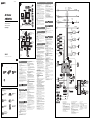 1
1
-
 2
2


El Sony XAV-W1 es un reproductor multimedia para automóvil con una amplia gama de características que mejorarán tu experiencia de conducción. Con su pantalla LCD de alta resolución, puedes ver fácilmente tus películas y videos favoritos, así como navegar por tus canciones y álbumes. También puedes conectar tu smartphone a través de Bluetooth para transmitir música o hacer llamadas con manos libres. Además, el XAV-W1 cuenta con una entrada para cámara retrovisora, para que puedas ver fácilmente lo que hay detrás de tu automóvil al dar marcha atrás.
en otros idiomas
- English: Sony XAV-W1 Installation guide