La página se está cargando...
La página se está cargando...

3
4.
1.
2.
3.
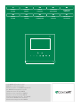
Art. 6602W
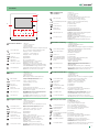
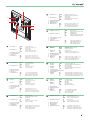
Descrizione monitor
Tasto / LED fonica
Tasto / LED apriporta
Tasti 1-2-3
Tasto autoaccensione
Tasto Privacy
LED Privacy - Dottore
Tasto video segreteria
Tasto porte aperte
fisso = fonica aperta / funzione Mani Libere attiva
lampeggio continuo = chiamata ricevuta
1 lampeggio = conferma apriporta
lampeggio continuo = porta aperta
(programmabili)
(programmabile)
fisso = funz. Privacy attiva
(programmabile) Dottore - Privacy+Dottore
4 lampeggi = dispositivo occupato
PREMUTO accesso alla sezione messaggi.
LUCE FISSA video segreteria / messaggio assente attivi.
LUCE LAMPEGGIANTE messaggio non letto in attesa.
LUCE FISSA segnala l'apertura di una o più porte
PREMUTO accesso alla sezione porte aperte.
1. Microfono
2. Schermo touch da 4.3"
3. Tasti a sfioramento
4. Porta per microSD
Amplificazione audio ad induzione magnetica integrata
Monitor
Audio key/LED
Lock-release key/LED
Keys 1-2-3
Self-ignition key
Privacy key
Privacy / Doctor LED
Video memory key
Open doors key
steady = audio enabled/hands-free function
continuous flashing = call received
1 flash = confirm lock-release
continuous flashing = door open
(programmable)
(programmable)
steady = Privacy function enabled
(programmable) Function Doctor , Privacy+Doctor
4 flashes = device engaged
PRESSED allows access to the messages section.
LIT STEADILY video memory / absent message active.
FLASHING new message waiting.
LIT STEADILY signals the opening of one or more doors
PRESSED allows access to the open doors section.
1. Microphone
2. 4.3" touch screen
3. Soft-touch keys
4. Micro SD card port
Built-in magnetic induction audio amplification
Description moniteur
Touche/LED phonie
Touche/LED ouvre-porte
Touches 1-2-3
Touche d'auto-allumage
Touche Privacy
Led Privacy / Docteur
Touche mémoire vidéo
Touche portes ouvertes
allumée = phonie ouverte/fonction mains libres
clignotement constant = appel reçu
1 clignotement = confirmation ouvre-porte
clignotement constant = porte ouverte
(programmables)
(programmable)
allumée = fonction Privacy ON
(programmable)
Fonct. Docteur,
Privacy+
Docteur
4 clignotements = dispositif occupé
ENFONCÉE : accès à la section messages.
ALLUMÉE : mémoire vidéo / message en cas
d'absence activés.
CLIGNOTE : message non lu en attente
ALLUMÉE : signale l'ouverture d'une ou de
plusieurs portes
ENFONCÉE : accès à la section portes ouvertes.
1. Micro
2. Écran tactile 4,3 pouces
3. Touches à effleurement
4. Port pour microSD
Amplification audio à boucle magnétique incorporée
Beschrijving van
de monitor
Audiotoets/-LED
Deurslotbedieningstoets-LED
Toets 1-2-3
Toets beeldoproep
Privacy-toets
Privacy/arts-LED
Videogeheugentoets
Toets deuren open
vast = audio open / handsfree-functie
continu knipperend = oproep ontvangen
knippert 1 maal = bevestig deurslotbediening
knippert continu = deur open
(programmeerbaar)
(programmeerbaar)
vast = Privacyfunctie actief
(programmeerbaar) Artsfunctie,
Privacyfunctie+Artsfunctie
knippert 4 maal = toestel bezet
INGEDRUKT, geeft toegang tot het berichtengedeelte.
BRANDT CONTINU: videogeheugen /
afwezigheidsmelding actief.
KNIPPERT: er is een ongelezen bericht.
BRANDT CONTINU: duidt op de opening van één of
meerdere deuren
INGEDRUKT geeft toegang tot het gedeelte 'deuren open'.
1. Microfoon
2. Touchscreen van 4.3"
3. Aanraaktoetsen
4. Poort voor Micro SD
Audioversterking met geïntegreerde inductiespoel
Monitorbeschreibung
Taste / LED Sprechtaste
Taste / LED Türöffner
Tasten 1-2-3
Taste Selbsteinschaltung
Taste Ruftonabschaltung
LED Ruftonabschaltung -
Arztruf
Taste Videospeicher
Taste Türen offen
leuchtet = Sprechverbindung besteht / Freisprechfunktion
Dauerblinken = Ruf empfangen
1 Blitz = Bestätigung Türöffner
Dauerblinken: Tür geöffnet
(programmierbar)
(programmierbar)
Leuchtet = Funktion Ruftonabschaltung aktiv
(programmierbar) Arztfunktion,
Ruftonabschaltung+Arztfunktion
4 Blitze = Gerät besetzt
GEDRÜCKT gibt Zugriff auf den Bereich Nachrichten.
LED LEUCHTET Videospeicher / Nachricht bei
Abwesenheit aktiv
LED BLINKT Nachricht nicht gelesen, in Erwartung
LED LEUCHTET zeigt an, dass eine oder mehrere Türen
offen ist/sind
GEDRÜCKT gibt Zugriff auf den Bereich Türen offen
1. Mikrofon
2. Touchscreen 4.3"
3. Berührungsempfindliche Tasten
4. Port für Mikro-SD
Audioverstärkung mit integrierter magnetischer Induktion
Descripción del monitor
Tecla / LED del audio
Tecla / LED del
abrepuertas
Teclas 1-2-3
Tecla de autoencendido
Tecla Privacidad
LED Privacidad - Doctor
Tecla Memo vídeo
Tecla Puertas abiertas
fijo = audio activado / función Manos Libres
parpadeo continuo = llamada recibida
1 parpadeo = confirmación abrepuertas
parpadeo continuo = puerta abierta
(programables)
(programable)
fijo = función Privacidad activada
(programable) Función Doctor, Privacidad+Doctor
4 parpadeos = dispositivo ocupado
PULSADA acceso a la sección Mensajes
LUZ FIJA memo vídeo/mensaje para ausente activados
LUZ PARPADEANTE mensaje no leído en espera
LUZ FIJA señala la apertura de una o más puertas
PULSADA permite el acceso a la sección Puertas abiertas
1. Micrófono
2. Pantalla táctil de 4,3"
3. Teclas táctiles
4. Puerto para microSD
Amplificación audio con inducción magnética integrada
Descrição do monitor
Tecla/Luz indicadora som
Tecla/Luz indicadora
abertura da porta
Teclas 1-2-3
Tecla acendimento automático
Tecla privacidade
Luz indicadora
Privacidade/Médico
Tecla vídeo-atendedor
Tecla portas abertas
Fixa = som activado/função mãos livres
Pisca continuamente = chamada recebida
Pisca 1 vez = confirmação da abertura da porta
Pisca continuamente = porta aberta
(programáveis)
(programável)
Fixa = função Privacidade activada
(programável) Função Médico, Privacidade+Médico
Pisca 4 vezes = dispositivo ocupado
PREMIDA: acesso à secção de mensagens
LUZ FIXA: vídeo-atendedor/mensagem ausência
activados
LUZ INTERMITENTE: mensagem não lida
LUZ FIXA: indicação da abertura de uma ou várias portas
PREMIDA: acesso à secção de portas abertas
1. Microfone
2. Touch-screen de 4.3"
3. Teclas tácteis
4. Porta para microSD card
Loop por indução magnética integrado
La página se está cargando...

5
4.
5.
6.
1.
2.
3.
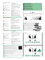
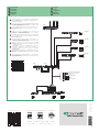
1. Morsettiera 1 OUT1 uscita ausiliaria +12V
V- negativo di riferimento ingressi
PAN ingresso panico
2. Morsettiera 2 AL ingresso allarme
V- negativo di riferimento ingressi
CFP ingresso chiamata fuori porta
3. Porta Micro SD card
4. Connettore Ethernet
5. Selettore S1
6. Morsettiera 3 OP- negativo ingresso optoisolato +12V
OP+ positivo ingresso optoisolato +12V
S- negativo uscita suoneria supplementare
S+ positivo uscita suoneria supplementare
1. Terminal block 1 OUT1 +12V auxiliary output
V- negative input reference
PAN panic input
2. Terminal block 2 AL alarm input
V- negative input reference
CFP floor door call input
3. Micro SD card port
4. Ethernet connector
5. Selector S1
6. Terminal block 3 OP- +12V opto-isolated input negative
OP+ +12V opto-isolated input positive
S- additional ringtone output negative
S+ additional ringtone output positive
1. Bornier 1 OUT1 sortie auxiliaire +12V
V- négatif de référence entrées
PAN entrée panique
2. Bornier 2 AL entrée alarme
V- négatif de référence entrées
CFP entrée appel porte palière
3. Port carte micro SD
4. Connecteur Ethernet
5. Sélecteur S1
6. Bornier 3 OP- négatif entrée opto isolée +12V
OP+ positif entrée opto isolée +12V
S- négatif sortie sonnerie supplémentaire
S+ positif sortie sonnerie supplémentaire
1. Klemmenblok 1 OUT1 extra uitgang +12V
V- negatieve referentiepool ingangen
PAN paniekingang
2. Klemmenblok 2 AL alarmingang
V- negatieve referentiepool ingangen
CFP ingang voor etagebel
3. Poort micro SD card
4. Ethernet-connector
5. Schakelaar S1
6. Klemmenblok 3 OP- negatieve ingang met opto-isolatie +12V
OP+ positieve ingang met opto-isolatie +12V
S- negatieve uitgang extra bel
S+ positieve uitgang extra bel
1. Klemmleiste 1 OUT1 Zusätzlicher Ausgang +12V
V- Minus Bezugsspannung Eingänge
PAN Panikeingang
2. Klemmleiste 2 AL Alarmeingang
V- Minus Bezugsspannung Eingänge
CFP Eingang Etagenruf
3. Slot für Mini SD-Kart
4. Ethernetstecker
5. Wahlschalter S1
6. Klemmleiste 3 OP- Minus optoisolierter Eingang +12V
OP+ Plus optoisolierter Eingang +12V
S- Minus Ausgang Zusatz-Läutewerk
S+ Plus Ausgang Zusatz-Läutewerk
1. Regleta de conexiones 1 OUT1 salida auxiliar +12V
V- negativo de referencia para las entradas
PAN entrada para pánico
2. Regleta de conexiones 2 AL entrada para alarma
V- negativo de referencia para las entradas
CFP entrada para llamada timbre de planta
3. Puerto para micro SD card
4. Conector Ethernet
5. Selector S1
6. Regleta de conexiones 3 OP- negativo entrada optoaislada +12V
OP+ positivo entrada optoaislada +12V
S- negativo salida timbre adicional
S- positivo salida timbre adicional
1. Bateria de OUT1 saída auxiliar +12 V
bornes 1 V- negativo de referência entradas
PAN entrada emergência
2. Bateria de AL entrada alarme
bornes 2 V- negativo de referência entradas
CFP entrada chamada campainha externa
3. Ranhura mini SD Card
4. Conector Ethernet
5. Selector S1
6. Bateria de OP- negativo entrada opto-acoplador +12 V
bornes 3 OP+ positivo entrada opto-acoplador +12 V
S- negativo saída campainha adicional
S+ positivo saída campainha adicional
1. Клеммная OUT1 вспомогательный выход +12V
колодка 1 V- отрицательная клемма для ориентации входов
PAN вход сигнала паники
2. Клеммная AL вход сигнала тревоги
колодка 2 V- отрицательная клемма для ориентации входов
CFP вход дверного вызова
3. Слот для карты SD
4. Разъем для подключения Ethernet
5. Переключатель S1
6.
Клеммная
OP- отрицательная клемма оптоизолированного входа +12V
колодка 3 OP+ положительная клемма оптоизолированного входа +12V
S- отрицательная клемма выхода дополнительного
звонка
S+ положительная клемма выхода дополнительного звонка
1. Bağlantı OUT1 +12V yardımcı çıkış
klemensi 1 V- giriş negatif referansı
PAN panik girişi
2. Bağlantı AL alarm girişi
klemensi 2 V- giriş negatif referansı
CFP kapı dışından arama girişi
3. SD Card yuvası
4. Ethernet Konektörü
5. Seçici S1
6. Bağlantı OP- +12V optik yalıtımlı giriş negatifi
klemensi 3 OP+ +12V optik yalıtımlı giriş pozitifi
S- ek zil sesi çıkış negatifi
S+ ek zil sesi çıkış pozitifi
1. Tabliczka zaciskowa 1 OUT1 wyjście dodatkowe +12V
V- ujemny odnoszący się do wejść
PAN wejście przycisku napadowego
2. Tabliczka zaciskowa 2 AL wejście alarmu
V- ujemny odnoszący się do wejść
CFP wejście wywołania zewnętrznego
3. Gniazdo karty SD
4. Złącze Ethernet
5. Przełącznik S1
6. Tabliczka zaciskowa 3 OP- ujemny wejście z optoizolacją +12V
OP+ dodatni wejście z optoizolacją +12V
S- ujemny wyjście dodatkowego dzwonka
S+ dodatni wyjście dodatkowego dzwonka

6
2
1
1
1
2
CLACK !
2
3
6
9
160 cm
130 cm
L
max
= 10 cm
L
min
= 6 cm
1
2
5
8
14,2 cm
14,7 cm
2
3
4
5
1
2
1
1
2
1
4
7
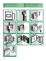
SMONTAGGIO / DISASSEMBLY
Installazione su scatola da incasso art. 6117
Icona Vip mounting on flush-mounted box art. 6117
Montage Icona ViP sur boîtier à encastrer art. 6117
Montage Icona ViP op inbouwdoos art. 6117
Montage Icona ViP in Unterputzgehäuse Art. 6117
Montaje de Icona ViP en caja de empotrar art. 6117
Montagem de Icone ViP na caixa de embutir art. 6117
Монтаж монитора Icona ViP во встраиваемый корпус арт. 6117
Icona ViP 'in ankastre kutuya (No. 6117) montajı
Montaż Icona ViP w puszce podtynkowej Art. 6117
La página se está cargando...

ORANGE
BLUE & WHITE BLUE
BROWN & WHITE BROWN
WHITE ORANGE
GREEN
WHITE GREEN
-
V V
+
++
-
TX
L
1441
OUT
43
OUTOUT
21
IN
21
IN
1440
+
-
OUT
N
-
+
V V
100-240 V
OUT
43
OUTOUT
21
IN
21
IN
1440
+
-
OUT
6802W
P
A
N
V
C
N
1
1
OUT
C
F
P
AL
S
+
S
-
0
1
IN
6702W
6602W
C
N
1
1
N
I
2
N
I
3
N
I
D
N
G
6722W
C
N
1
1
N
I
2
N
I
3
N
I
D
N
G
J1J1
J2
E
S
NC NO
GND
-
V V
+
M
O
C
4682HD
R
T
E
RX
-
+
RXTX
+
-
TX
33436
SE-
+
ES
DE
Collegamento
Connection
Connexion
Aansluiting
Anschluss
Conexión
Ligação
Соединение
Bağlantısı
Podłączenie
2ª edizione 12/2018
cod. 2G40002374
ViP Manager
www.comelitgroup.com
Via Don Arrigoni, 5 - 24020 Rovetta (BG) - Italy
CERTIFIED MANAGEMENT SYSTEMS
Consultare il manuale tecnico del Sistema ViP (scaricabile dal sito
www.comelitgroup.com) per l'installazione, la programmazione e la
configurazione dell'impianto.
Please refer to the ViP System Technical Manual (available to download
from www.comelitgroup.com) for information regarding system
installation, programming and configuration.
Consulter le Manuel technique du système ViP (à télécharger sur :
www.comelitgroup.com) pour installer, programmer et configurer
le circuit.
Raadpleeg de technische handleiding van het ViP-systeem (te
downloaden via www.comelitgroup.com) voor het installeren,
programmeren en configureren van het systeem.
Für Installation, Programmierung und Konfiguration der Anlage bitte im
technischen Handbuch des ViP-Systems nachschlagen (Download auf:
www.comelitgroup.com).
Para más información sobre la instalación, la programación y la
configuración del sistema, consultar el Manual Técnico del Sistema ViP
(descargable en: www.comelitgroup.com).
Consultar o manual técnico do sistema ViP (transferir em: www.
comelitgroup.com) para informações sobre a instalação, programação
e configuração do sistema.
За информацией по монтажу, программированию и настройке
оборудования обращайтесь к техническому руководству по
эксплуатации системы ViP (его можно загрузить на сайте www.
comelitgroup.com).
Sistemin kurulumu, programlanması ve yapılandırılması için ViP Sistemi
Teknik Kılavuzuna (www.comelitgroup.com adresinden yüklenebilir)
başvurun.
Przed zainstalowaniem, zaprogramowaniem i skonfigurowaniem
Systemu ViP zapoznać się z instrukcją techniczną (dostępna na stronie:
www.comelitgroup.com).
Transcripción de documentos
Art. 6602W 1. 2. 4. Beschrijving van de monitor Audiotoets/-LED vast = audio open / handsfree-functie continu knipperend = oproep ontvangen Deurslotbedieningstoets-LED knippert 1 maal = bevestig deurslotbediening knippert continu = deur open Toets 1-2-3 (programmeerbaar) Toets beeldoproep (programmeerbaar) Privacy-toets Privacy/arts-LED vast = Privacyfunctie actief (programmeerbaar) Artsfunctie, Privacyfunctie+Artsfunctie knippert 4 maal = toestel bezet Videogeheugentoets INGEDRUKT, geeft toegang tot het berichtengedeelte. BRANDT CONTINU: videogeheugen / afwezigheidsmelding actief. KNIPPERT: er is een ongelezen bericht. Toets deuren open BRANDT CONTINU: duidt op de opening van één of meerdere deuren INGEDRUKT geeft toegang tot het gedeelte 'deuren open'. 3. Descrizione monitor 1. Microfono 2. Schermo touch da 4.3" 3. Tasti a sfioramento 4. Porta per microSD Amplificazione audio ad induzione magnetica integrata 1. Microfoon 2. Touchscreen van 4.3" 3. Aanraaktoetsen 4. Poort voor Micro SD Audioversterking met geïntegreerde inductiespoel Monitorbeschreibung 1. Mikrofon 2. Touchscreen 4.3" 3. Berührungsempfindliche Tasten 4. Port für Mikro-SD Audioverstärkung mit integrierter magnetischer Induktion Taste / LED Sprechtaste Tasto / LED fonica fisso = fonica aperta / funzione Mani Libere attiva lampeggio continuo = chiamata ricevuta leuchtet = Sprechverbindung besteht / Freisprechfunktion Dauerblinken = Ruf empfangen Taste / LED Türöffner Tasto / LED apriporta 1 lampeggio = conferma apriporta lampeggio continuo = porta aperta 1 Blitz = Bestätigung Türöffner Dauerblinken: Tür geöffnet Tasten 1-2-3 (programmierbar) Tasti 1-2-3 (programmabili) Taste Selbsteinschaltung (programmierbar) Tasto autoaccensione (programmabile) Tasto Privacy LED Privacy - Dottore fisso = funz. Privacy attiva (programmabile) Dottore - Privacy+Dottore 4 lampeggi = dispositivo occupato Taste Ruftonabschaltung LED Ruftonabschaltung Arztruf Leuchtet = Funktion Ruftonabschaltung aktiv (programmierbar) Arztfunktion, Ruftonabschaltung+Arztfunktion 4 Blitze = Gerät besetzt Tasto video segreteria PREMUTO accesso alla sezione messaggi. LUCE FISSA video segreteria / messaggio assente attivi. LUCE LAMPEGGIANTE messaggio non letto in attesa. Taste Videospeicher GEDRÜCKT gibt Zugriff auf den Bereich Nachrichten. LED LEUCHTET Videospeicher / Nachricht bei Abwesenheit aktiv LED BLINKT Nachricht nicht gelesen, in Erwartung Tasto porte aperte LUCE FISSA segnala l'apertura di una o più porte PREMUTO accesso alla sezione porte aperte. Taste Türen offen LED LEUCHTET zeigt an, dass eine oder mehrere Türen offen ist/sind GEDRÜCKT gibt Zugriff auf den Bereich Türen offen Monitor 1. Microphone 2. 4.3" touch screen 3. Soft-touch keys 4. Micro SD card port Built-in magnetic induction audio amplification Descripción del monitor 1. Micrófono 2. Pantalla táctil de 4,3" 3. Teclas táctiles 4. Puerto para microSD Amplificación audio con inducción magnética integrada Audio key/LED steady = audio enabled/hands-free function continuous flashing = call received Tecla / LED del audio fijo = audio activado / función Manos Libres parpadeo continuo = llamada recibida Lock-release key/LED 1 flash = confirm lock-release continuous flashing = door open Tecla / LED del abrepuertas 1 parpadeo = confirmación abrepuertas parpadeo continuo = puerta abierta Keys 1-2-3 (programmable) Teclas 1-2-3 (programables) Self-ignition key (programmable) Tecla de autoencendido (programable) Privacy key Privacy / Doctor LED steady = Privacy function enabled (programmable) Function Doctor , Privacy+Doctor 4 flashes = device engaged Tecla Privacidad LED Privacidad - Doctor fijo = función Privacidad activada (programable) Función Doctor, Privacidad+Doctor 4 parpadeos = dispositivo ocupado Video memory key PRESSED allows access to the messages section. LIT STEADILY video memory / absent message active. FLASHING new message waiting. Tecla Memo vídeo PULSADA acceso a la sección Mensajes LUZ FIJA memo vídeo/mensaje para ausente activados LUZ PARPADEANTE mensaje no leído en espera Open doors key LIT STEADILY signals the opening of one or more doors PRESSED allows access to the open doors section. Tecla Puertas abiertas LUZ FIJA señala la apertura de una o más puertas PULSADA permite el acceso a la sección Puertas abiertas Description moniteur 1. Micro 2. Écran tactile 4,3 pouces 3. Touches à effleurement 4. Port pour microSD Amplification audio à boucle magnétique incorporée Touche/LED phonie allumée = phonie ouverte/fonction mains libres clignotement constant = appel reçu Touche/LED ouvre-porte 1 clignotement = confirmation ouvre-porte clignotement constant = porte ouverte Touches 1-2-3 (programmables) Touche d'auto-allumage (programmable) Touche Privacy Led Privacy / Docteur allumée = fonction Privacy ON (programmable) Fonct. Docteur, Privacy+Docteur 4 clignotements = dispositif occupé Touche mémoire vidéo ENFONCÉE : accès à la section messages. ALLUMÉE : mémoire vidéo / message en cas d'absence activés. CLIGNOTE : message non lu en attente Touche portes ouvertes ALLUMÉE : signale l'ouverture d'une ou de plusieurs portes ENFONCÉE : accès à la section portes ouvertes. Descrição do monitor 1. Microfone 2. Touch-screen de 4.3" 3. Teclas tácteis 4. Porta para microSD card Loop por indução magnética integrado Tecla/Luz indicadora som Fixa = som activado/função mãos livres Pisca continuamente = chamada recebida Tecla/Luz indicadora abertura da porta Pisca 1 vez = confirmação da abertura da porta Pisca continuamente = porta aberta Teclas 1-2-3 (programáveis) Tecla acendimento automático (programável) Tecla privacidade Luz indicadora Privacidade/Médico Fixa = função Privacidade activada (programável) Função Médico, Privacidade+Médico Pisca 4 vezes = dispositivo ocupado Tecla vídeo-atendedor PREMIDA: acesso à secção de mensagens LUZ FIXA: vídeo-atendedor/mensagem ausência activados LUZ INTERMITENTE: mensagem não lida Tecla portas abertas LUZ FIXA: indicação da abertura de uma ou várias portas PREMIDA: acesso à secção de portas abertas 3 1. 6. 5. 2. 3. 1. Klemmleiste 1 OUT1 V PAN 2. Klemmleiste 2 AL V CFP 3. Slot für Mini SD-Kart 4. Ethernetstecker 5. Wahlschalter S1 6. Klemmleiste 3 OP OP+ S S+ Zusätzlicher Ausgang +12V Minus Bezugsspannung Eingänge Panikeingang Alarmeingang Minus Bezugsspannung Eingänge Eingang Etagenruf Minus optoisolierter Eingang +12V Plus optoisolierter Eingang +12V Minus Ausgang Zusatz-Läutewerk Plus Ausgang Zusatz-Läutewerk 1. Regleta de conexiones 1 OUT1 V PAN 2. Regleta de conexiones 2 AL V CFP 3. Puerto para micro SD card 4. Conector Ethernet 5. Selector S1 6. Regleta de conexiones 3 OP OP+ S S- 4. 1. Morsettiera 1 2. Morsettiera 2 3. Porta Micro SD card 4. Connettore Ethernet 5. Selettore S1 6. Morsettiera 3 OUT1 VPAN AL VCFP uscita ausiliaria +12V negativo di riferimento ingressi ingresso panico ingresso allarme negativo di riferimento ingressi ingresso chiamata fuori porta OPOP+ SS+ negativo ingresso optoisolato +12V positivo ingresso optoisolato +12V negativo uscita suoneria supplementare positivo uscita suoneria supplementare 1. Terminal block 1 2. Terminal block 2 3. Micro SD card port 4. Ethernet connector 5. Selector S1 6. Terminal block 3 OUT1 VPAN AL VCFP +12V auxiliary output negative input reference panic input alarm input negative input reference floor door call input OPOP+ SS+ +12V opto-isolated input negative +12V opto-isolated input positive additional ringtone output negative additional ringtone output positive 1. Bornier 1 OUT1 V PAN 2. Bornier 2 AL V CFP 3. Port carte micro SD 4. Connecteur Ethernet 5. Sélecteur S1 6. Bornier 3 OP OP+ S S+ sortie auxiliaire +12V négatif de référence entrées entrée panique entrée alarme négatif de référence entrées entrée appel porte palière 1. Klemmenblok 1 2. Klemmenblok 2 3. Poort micro SD card 4. Ethernet-connector 5. Schakelaar S1 6. Klemmenblok 3 OUT1 VPAN AL VCFP extra uitgang +12V negatieve referentiepool ingangen paniekingang alarmingang negatieve referentiepool ingangen ingang voor etagebel OPOP+ SS+ negatieve ingang met opto-isolatie +12V positieve ingang met opto-isolatie +12V negatieve uitgang extra bel positieve uitgang extra bel négatif entrée opto isolée +12V positif entrée opto isolée +12V négatif sortie sonnerie supplémentaire positif sortie sonnerie supplémentaire salida auxiliar +12V negativo de referencia para las entradas entrada para pánico entrada para alarma negativo de referencia para las entradas entrada para llamada timbre de planta negativo entrada optoaislada +12V positivo entrada optoaislada +12V negativo salida timbre adicional positivo salida timbre adicional 1. Bateria de OUT1 bornes 1 V PAN 2. Bateria de AL bornes 2 V CFP 3. Ranhura mini SD Card 4. Conector Ethernet 5. Selector S1 6. Bateria de OPbornes 3 OP+ S S+ saída auxiliar +12 V negativo de referência entradas entrada emergência entrada alarme negativo de referência entradas entrada chamada campainha externa 1. Клеммная OUT1 колодка 1 V PAN 2. Клеммная AL колодка 2 V CFP 3. Слот для карты SD 4. Разъем для подключения Ethernet 5. Переключатель S1 6. Клеммная OPколодка 3 OP+ S S+ вспомогательный выход +12V отрицательная клемма для ориентации входов вход сигнала паники вход сигнала тревоги отрицательная клемма для ориентации входов вход дверного вызова 1. Bağlantı klemensi 1 2. Bağlantı klemensi 2 3. SD Card yuvası 4. Ethernet Konektörü 5. Seçici S1 6. Bağlantı klemensi 3 OUT1 VPAN AL VCFP +12V yardımcı çıkış giriş negatif referansı panik girişi alarm girişi giriş negatif referansı kapı dışından arama girişi OPOP+ SS+ +12V optik yalıtımlı giriş negatifi +12V optik yalıtımlı giriş pozitifi ek zil sesi çıkış negatifi ek zil sesi çıkış pozitifi 1. Tabliczka zaciskowa 1 2. Tabliczka zaciskowa 2 3. Gniazdo karty SD 4. Złącze Ethernet 5. Przełącznik S1 6. Tabliczka zaciskowa 3 negativo entrada opto-acoplador +12 V positivo entrada opto-acoplador +12 V negativo saída campainha adicional positivo saída campainha adicional отрицательная клемма оптоизолированного входа +12V положительная клемма оптоизолированного входа +12V отрицательная клемма выхода дополнительного звонка положительная клемма выхода дополнительного звонка OUT1 VPAN AL VCFP wyjście dodatkowe +12V ujemny odnoszący się do wejść wejście przycisku napadowego wejście alarmu ujemny odnoszący się do wejść wejście wywołania zewnętrznego OPOP+ SS+ ujemny wejście z optoizolacją +12V dodatni wejście z optoizolacją +12V ujemny wyjście dodatkowego dzwonka dodatni wyjście dodatkowego dzwonka 5 Installazione su scatola da incasso art. 6117 Icona Vip mounting on flush-mounted box art. 6117 Montage Icona ViP sur boîtier à encastrer art. 6117 Montage Icona ViP op inbouwdoos art. 6117 Montage Icona ViP in Unterputzgehäuse Art. 6117 Montaje de Icona ViP en caja de empotrar art. 6117 Montagem de Icone ViP na caixa de embutir art. 6117 Монтаж монитора Icona ViP во встраиваемый корпус арт. 6117 Icona ViP 'in ankastre kutuya (No. 6117) montajı Montaż Icona ViP w puszce podtynkowej Art. 6117 160 cm 14,7 cm 1 130 cm 14,2 cm 2 3 2 3 L min = 6 cm 5 L max = 10 cm 1 2 4 1 4 5 6 CLACK ! 2 2 1 1 2 1 7 8 1 2 SMONTAGGIO / DISASSEMBLY 6 9 1 Collegamento Conexión Connection Ligação Connexion Соединение Aansluiting Bağlantısı Anschluss Podłączenie Consultare il manuale tecnico del Sistema ViP (scaricabile dal sito www.comelitgroup.com) per l'installazione, la programmazione e la configurazione dell'impianto. Please refer to the ViP System Technical Manual (available to download from www.comelitgroup.com) for information regarding system installation, programming and configuration. 1440 + Consulter le Manuel technique du système ViP (à télécharger sur : www.comelitgroup.com) pour installer, programmer et configurer le circuit. IN IN 1 2 - OUT OUT OUT OUT 1 2 3 4 Raadpleeg de technische handleiding van het ViP-systeem (te downloaden via www.comelitgroup.com) voor het installeren, programmeren en configureren van het systeem. DE Für Installation, Programmierung und Konfiguration der Anlage bitte im technischen Handbuch des ViP-Systems nachschlagen (Download auf: www.comelitgroup.com). ES Para más información sobre la instalación, la programación y la configuración del sistema, consultar el Manual Técnico del Sistema ViP (descargable en: www.comelitgroup.com). 6602W C N 1 I N 1 I N 2 I N 3 G N D C N 1 I N 1 I N 2 I N 3 G N D C N 1 S S + - 6702W Consultar o manual técnico do sistema ViP (transferir em: www. comelitgroup.com) para informações sobre a instalação, programação e configuração do sistema. За информацией по монтажу, программированию и настройке оборудования обращайтесь к техническому руководству по эксплуатации системы ViP (его можно загрузить на сайте www. comelitgroup.com). Sistemin kurulumu, programlanması ve yapılandırılması için ViP Sistemi Teknik Kılavuzuna (www.comelitgroup.com adresinden yüklenebilir) başvurun. Przed zainstalowaniem, zaprogramowaniem i skonfigurowaniem Systemu ViP zapoznać się z instrukcją techniczną (dostępna na stronie: www.comelitgroup.com). AL 0 V C F P P A N IN OUT 1 1 6722W 6802W 1440 1441 L N - + V V + - IN IN 1 2 OUT OUT OUT OUT 1 2 3 4 100-240 V V V TX + - - BROWN & WHITE BROWN BLUE & WHITE BLUE ORANGE + WHITE ORANGE GREEN + C O M GND R T E NC NO SE- V V TX TX RX RX + - + - + - 4682HD ViP Manager CERTIFIED MANAGEMENT SYSTEMS w w w.comelitgroup.com Via Don Arrigoni, 5 - 24020 Rovetta (BG) - Italy J1 J1 J2 33436 2ª edizione 12/2018 cod. 2G40002374 S+ E WHITE GREEN-
 1
1
-
 2
2
-
 3
3
-
 4
4
-
 5
5
-
 6
6
-
 7
7
-
 8
8


Comelit Icona ViP 6602W El manual del propietario
- Tipo
- El manual del propietario
- Este manual también es adecuado para
en otros idiomas
- français: Comelit Icona ViP 6602W Le manuel du propriétaire
- italiano: Comelit Icona ViP 6602W Manuale del proprietario
- English: Comelit Icona ViP 6602W Owner's manual
- Deutsch: Comelit Icona ViP 6602W Bedienungsanleitung
- русский: Comelit Icona ViP 6602W Инструкция по применению
- Nederlands: Comelit Icona ViP 6602W de handleiding
- português: Comelit Icona ViP 6602W Manual do proprietário
- polski: Comelit Icona ViP 6602W Instrukcja obsługi
- Türkçe: Comelit Icona ViP 6602W El kitabı
Artículos relacionados
-
Comelit Mini 6750W Manual de usuario
-
-
-
-
-
-
Comelit 6702W El manual del propietario
-
-
-