
Owner's Manual
Manual del Propietario
®
HEAT / COOL AIR CONDITIONER
EICALOR / REFRESCA ACONDICIONADOR
DE AIRE DE VENTANA
Model, Modelo 580.72077
Sears, Roebuck and Co., Hoffman Estates, IL 60179 U.S.A.
www.sears.com

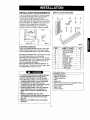
TABLE OF CONTENTS ........................2
WARRANTY ..............................................2
SAFETY .....................................................3
Important Safety Instructions ...................... 3
ELECTRICAL REQUIREMENTS .......4
INSTALLATION ........................................ 5
installation Requirements ......................... 5
Installation................................................ 6
Hew to Install ............................................ 6
Removalfrom Window................................. 8
OPERATION ............................................. 9
How and Why ........................................... 9
Normal Sounds ........................................ 9
Capacity and Running Time ..................... 9
Features ................................................. 10
Using the Air Conditioner ....................... 10
Display ................................................... f 1
MAINTENANCE .....................................12
Air Filter Cleaning ................................... 12
Air Conditioner Cleaning ........................ 12
How to Remove the Front Grille .................. 12
How to Replace the Front Grille .................. 12
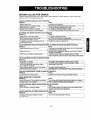
TROUBLESHOOTING .........................13
Before Calling for Service ...................... 13
REPAIR PARTS ....................................14
ESPANOL ................................................24
SERVICE NUMBERS ............BackCover
FULL ONE YEAR WARRANTY ON
ROOM AIR CONDITIONER
For one year from the date of purchase, when this
air conditioner is operated and maintained for
normal room cooling according to instructions in this
owner's manual, Sears will repair this air
conditioner, free of charge, if defective in material or
workmanship,
FULL FIVE-YEAR WARRANTY ON
SEALED REFRIGERATION SYSTEM
For five years from the date of purchase, when this
air conditioner is operated and maintained for
normal room cooling according to instructions in this
owner's manual, Sears will repair the sealed
refrigeration system (consisting of refrigerant,
connecting tubing, and compressor), free of charge,
if defective in material or workmanship.
WARRAN'I:Y SERVICE IS AVAILABLE BY
CONTACTING SEARS SERVICE AT
1-800-4-MY-HOME ®
Warranty coverage applies only to air conditioners
used for non-commercial, private household
purposes.
This warranty applies only while this product is in
use in the United States.
This warranty gives you specific legal rights, and
you may also have other rightwhich vary from state
to state.
Sears, Roebuck and Co., D/617WA,
Hoffman Estates, IL 60179 U.S.A.
_2-

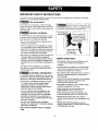
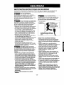
IMPORTANT SAFETY INSTRUCTIONS
The safety instructions below will tell you how to use your room air conditioner to avoid harm to yourself or
damage to your ROOM AIR CONDITIONER.
FOR YOUR SAFETY
Do not store or use gasoline or other flammable
vapors and liquids in the vicinity of this or any other
appliance. Read product labels for flammability and
other warnings.
PREVENT ACCIDENTS
To reduce the risk of fire, electrical shock, or injury
to persons when using your air conditioner, follow
basic precautions, including the following:
• Be sure the electrical service is adequate for the
model you have chosen.
• If the air conditioner is to be installed in a window,
you will probably want to clean both sides of the
glass first. If the window is a triple-track type with a
screen panel included, you may want to remove
the screen completely before installation.
• Be sure the air conditioner has been securely and
correctly installed according to the separate
installation instructions provided with this manual.
Save this manual and installation instructions for
possible future use in removing or reinstalling this
unit.
• Use gloves when handling the air conditioner.
Be careful to avoid cuts from sharp metal fins on
front and rear coils.
ELECTRICAL INFORMATION
The complete electrical rating of your new room air
conditioner is stated on the serial plate. Refer to the
rating when checking the electrical requirements.
• Be sure the air conditioner is properly grounded.
To minimize shock and fire hazards, proper
grounding is important. The power cord is
equipped with a three-prong grounding plug for
protection against shock hazards.
• Your air conditioner must be plugged into in a
propedy grounded wall receptacle. If the wall
receptacle you intend to use is not adequately
grounded or protected by a time delay fuse or
circuit breaker, have a qualified electrician install
the proper receptacle.
• Do not run air conditioner with a protective
covering. This could result in mechanical damage
within the air conditioner.
• Do not use an extension cord or an adapter
plug.
_J Avoid fire hazard or electric shock. Do
not use an extension cord or an adapter plug.
Do not remove any prong from the power cord.
Grounding type
]
Do not, under any
circumstances, cut,
remove, or bypass
the grounding prong
from this plug.
Power supply cord
with 3-prong _
grounding plug \,
ENERGY SAVING IDEAS
• The capacity of the room air conditioner must fit
the room size for efficient and satisfactory
operation.
• Install the room air conditioner on the shady side
of your home. A window that faces north is best
because it is shaded most of the day.
• Do not block air flow inside with blinds, curtains, or
furniture, or outsJde with shrubs, enclosures, or
other buildings.
• Close the floor and wall registers and the fireplace
damper so cool air does not escape up the
chimney and into the duct work.
• Keep blinds and drapes in other windows closed
during the sunniest part of the day.
• Clean the air filter as recommended in the
MAINTENANCE section of this manual.
• Proper insulation and weather stripping in your
home will help keep warm air out and cool air in.
• External house shading with trees, plants or
awnings will help reduce the air conditioner's work
load.
• Operate heat producing appliances such as
ranges, washers, dryers, and dishwashers during
the coolest part of the day.
!
-3-

OBSERVE ALL LOCAL CODES AND
ORDINANCES.
DO NOT, UNDER ANY CIRCUMSTANCES,
REMOVE THE POWER SUPPLY CORD
GROUND PRONG.
ELECTRICAL GROUND IS REQUIRED ON
THIS APPLIANCE.
A 115-volt 60 Hz, AC only, 15A fused and
properly grounded electrical supply is required.
A time delay fuse or time delay circuit breaker
is recommended. Use a dedicated circuit,
serving only this appliance.
DO NOT USE AN EXTENSION CORD.
RECOMMENDED GROUNDING METHOD
For your personal safety, this appliance must
be grounded. This appliance has a power
supply cord with a 3-prong grounding plug. To
minimize possible shock hazard, the cord must
be plugged into a mating grounding type wall
receptacle and grounded in accordance with
the National Electrical Code (ANSI/NFPA 70)
latest edition and all local codes and
ordinances. If a mating wall receptacle is not
available, it is the personal responsibility and
obligation of the customer to have a properly
grounded 3-prong wall receptacle installed by a
qualified electrician.
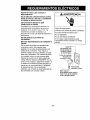
,AWARNING
Electrical Shock Hazard
Plug into a grounded 3 prong outlet.
Do not remove ground prong.
Do not use an adapter.
Do not use an extension cord.
Failure to follow these instructions can result
in death, fire, or electrical shock.
_3-prong
_r__ J grounding
3-prong -__ _ I1(]_"_ I type wall
grounding "_,_plug _ receptacle
Ground
Power _ prong
supply
cord
-4-

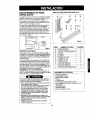
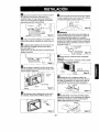
INSTALLATION REQUIREMENTS
Your air conditioner will install into standard double
hung windows with actual clear opening widths of
22 to 36 inches (559mm to 915mm) (FIG. 1).
Lower sash must open sufficiently to allow a clear
vertical opening of 15 inches (381mm). Side louvers
and the rear of the air conditioner must have clear
air space to allow enough airflow through the
condenser for heat removal. The rear of the unit
must be outdoors, not inside a building or garage.
22"_O36"
I 1is.,in innersillL| Window
II O,set
Interiorwall "',J o[," FIG. 1
ELECTRICAL SERVICE
Check your available electrical service. The power
supply available must be the same as that shown
on the unit nameplate (foundon rightside of cabinet),
All models are equipped with a 3-prong service plug
to provide proper service and safe positive
grounding. Do not change plug in any way. Do not
use an adapter plug. If your present wall outlet does
not match your plug, call a qualified electrician to
make the necessary corrections.
SAVE CARTON and this OWNER'S MANUAL for
future reference. The carton is the best way to store
unit during winter or when not in use.
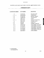
INSTALLATION HARDWARE
ITEM
A
B
C
D
E
F
FIG. 2
i
f
I
REQUIRED TOOLS:
NAME OF PARTS
SIDE CURTAIN
SILL SUPPORT
BOLT
LOCK NUT
SCREW: 25/64"
SCREW: 5/8"
SCREW: 5/8"
FOAM SEAL
FOAM STRIP
L BRACKET
Q'TY
2
2
2
2
13
3
5
1
1
1
To avoidrisk ofpersonal injury,propertydamage,
or product damage due to theweightofthis
device and sharp edges that may be exposed:
• Air conditioners covered in this manual pose an
excessive weight hazard. Two or more people
are needed to move and install the unit.
To prevent injury or strain, use proper lifting and
carrying techniques when moving unit.
Carefully inspect location where air conditioner
will be installed. Be sure it will support the
weight of the unit over an extended periodof
time.
i Handleair conditioner with care. Wear
protective gloves whenever liftingor carrying the
unit. AVOID the sharp metalfins of front and
rear coils.
Make sure air conditioner does not fall during
installation.
• Tight Fitting gloves
• Standard screwdriver
• Phillips screwdriver
• Pliers
• Sharp knife
• 3/8-inch open end wrench or adjustable wrench
• 1/4-inch hex socket and ratcher
• Tape measure
Electric drill
1/4-inch drill bit
-5-

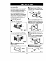
INSTALLATION
Pick a location whichwill allow you to blow the cold air
into the area you want. Windows used for installation
must be strong enough to support the weight of the air
conditioner. Good installation with special attention to
the proper positionof the unit will lessen the chance
that service will be needed.
When cooling more than one room, installation location
is very important, if air conditioner is blocked by a
storm window frame, see step 19 on page 8 before
beginning toinstall. To cool your rooms, cold air must
be blown from the air conditioner in a straight path.
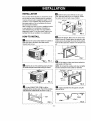
HOW TO INSTALL
B Remove the screws which fasten the cabinet at
both sides and at the back. Save side screws.
Discard back screws.
FIG. 3
[]Slide the unit outofthe cabinet bygripping the base
)an handle andpull forward while bracing the cabinet.
FIG. 4
_1 Cut the FOAM STRIP (ITEM I) to fit the
underside of the window sash. Peel off the backing
and attach the FOAM STRIP as shown in Fig. 5.
FIG. 5
_! Insert the side curtain (ITEM A) into the upper
guide and lowerguide of the air conditioner. Fasten
the curtains to the unit with screws (ITEM E).
ITEM E
ITEM E FIG. 6
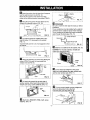
O Open the window. Mark a line on center of the
window inner sill. Carefully place the cabinet on the
window inner sill and align the center of the cabinet
front with the center line marked in the window inner
sill.
Windowsill
FIG, 7
r_ Pull the bottom window sash down behind the
upper guide until they meet.
NOTE: Do not pull the window sash down so tightly
that the movement of side curtain is restricted.
Window sash
Cabinel
Side Curtain
FIG. 8
[] Loosely assemble the sill supports using the
parts in FIG. 9.
ITEM 8
ITEM C_'e'-= _ITEM [3
FIG. 9
-6-

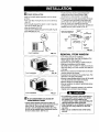
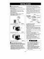
I_ Select the position that will place the sill supports
near the outermost point on sill (FIG. 10).
Attach the sill supports to the cabinet track hole
closest to the selected position using screw (ITEM E).
I_ Place the sill supports with the cabinet on the
window sill's selected position (FIG. 10).
iTEM E
FIG. 14
[] DRAINAGE
Be sure to insert the drain pipe into base pan before
installation.
The air conditioner must be installed with a slight tilt
downward to the outside for proper water drainage.
The air conditioner will drain the excess condensed
water through the drain pipe. (FIG. 15)
_1'_ The cabinet should be installed with a very
slight tilt (about 1/4") downward to the outside
(FIG. 11).
Adjust the bolts and the nuts of sill supports to level
the cabinet.
\
ITEM B FIG. 11
_111Attach the cabinet to the inner sill by driving the
screws (ITEM F) through the lower guide into
window inner sill (FIG 12).
Track
Lower Guide
ITEM F FIG. 12
ITEM B
_] Pull each side curtain fully to each side of
window opening. Attach each side curtain to the
window sash using screws (ITEM G). (FIG. 13)
. ITEM G
_J_ FIG. 13
i'l_ Attach the L BRACKET (ITEM J) with screw
(ITEM G). (FIG. 14)
DRAIN PIPE
PANBO]qOM
FIG, 15
_J Slide the air conditioner into the cabinet. (FIG. 16)
CAUTION: For security purposes, reinstall side
screws you removed in step 1.
-7-
Screw
•Power
Cord
/
Screw FIG. 16
_1"_ Cut the foar_ seal (ITEM H) to the proper
length and insert between the upper window sash
and the lower window sash. (FIG. 17)
FIG. 17
_'_ The vent controT handle must be straightened
before the decorative front is attached.
Pug down part _)to align with part _,
Part (_
FIG. 18

_] FRONT INSTALLATION
Installthe front grille (packed separately)ontothe cabinet
asfollows:
• Hook uppertabs offront grille into slotson thecabinettop
(FIG. 19)
• Push front gdlle towards the cabinet inorder to snapside
tabs intothe cabinet (FIG. 19)
• Open the inlet grille. (FIG. 20)
• Installthescrew (ITEME) through the front grille.(Fig. 20)
• Close inletgrille (Fig. 21)
.'1
Front Installation
FIG. 19
grille
Front Installation FIG. 20
Front Installation FIG. 21
_"] IF AIR CONDITIONER IS BLOCKED BY
STORM WINDOW FRAME
• Ifstorm window presents interference, fasten a2"
wide wood strip to the inner window sill across the full
width of the sill. The wood strip should be thick
enough to raise the height of the window sill so that
the unit can be installed without interference from the
the storm window frame. See FIG. 22.
Top of wood strip should be approximately 3/4"
higher than the storm window frame to help
condensation to drain properly to the outside.
• Install a second wood strip (approximately 6" long by
1_/2"wide and same thickness as first strip) in the
center of the outer sill flush against the back of the
inner sill. Screw the L brackets into this strip.
To support the lower guide, screw an "L"bracket (not
supplied) into this strip as shown in FIG. 22.
1 1/2" rain
WOOD STRIP MOUNTED (38mrn)
ON TOP OF INNER SILL ="'-I _ 3/4" ,
] CLEARANCE
J _WlNDOW i
INNER FRAME
SILL
OUTER
SiLL
I TSIDj=
FIG, 22
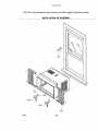
REMOVAL FROM WINDOW
•Turn off and unplug the air conditioner.
• Remove the front gdlle. See HOWTO REMOVETHE
FRONT GRILLE. Referto page 12.
• Unscrew the side screws thatyou installed in Step 15.
• Slide the air conditioner out of the cabinet.
BE CAREFUL NOTTO DROP IT. Holdonto it firmly the
whole way sliding it out Once removed, set it safetyout
of the way.
• Remove the L bracket from window frame and the sash
seal from between the windows.
• Unscrew the side curtains from the window frame. Fold
them back to the sides ofthe cabinet,
• Remove screws attaching cabinet to innersill. Be careful
not to let cabinet fall oncescrews are removed.
• Remove cabinet from window opening.
• Place air conditioner into cabinet. Reinstallside screws
and Front Grille.
• Place unit and all assembly hardware in air conditioner
shipping carton, and store in clean,dry place.
•Air conditioners covered in this manualposean
excessive weight hazard.Two or morepeople
are needed to move and install the unit.
To prevent injuryor strain, use proper lifting and
carrying techniques when moving unit.
• When handling the air conditioner, be careful to
avoid cuts from sharp metalfins on front and
rear coils.
• Make sure air conditioner doesnot fall during
removal.
-8-

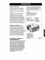
HOW AND WHY
Your room air conditioner provides the following
functions to make hot weather living more
comfortable:
• Cools and circulates room air.
• Lowers humidity by removing excess moisture.
• Filters out summertime dust, dirt, and some
airborne impurities.
The air conditioner performs these functions by
drawing room air through a filter which traps dust
and dirt particles. The air then passes over a
cooling coil which refrigerates the air and removes
excess moisture. The same air is then returned to
the room- cooler, drier, and cleaner. Moisture
removed from the room air is carried to the outside
and evaporated.
Your air conditioner is designed to be easy to
operate and to provide plenty of cooling power.
NORMAL SOUNDS F,G.23
Aside from the regular fan motor and compressor
sounds coming from your air conditioner, you will
once in a while hear a pinging sound. This isthe
result of moisture being picked up from the air in the
room and thrown against the air conditioner's fan.
This is normal and should not be cause for concern.
Also, do not be alarmed ifyou hear a slight hissing
or gurgling sound coming from your air conditioner
after it isoft. These are normal coolant noises.
i ompressor
The modern high efficiency
compressor may have a high
pitched hum or pulsating
noise that cycles on and off.
You may hear
droplets of water
hitting the condenser
causing a pinging or
clicking sound.
Fan
You may hear air
movement from
the fan.
FIG. 23
CAPACITY AND RUNNING TIME
Proper unit size is important in deciding the desired
comfort for the area you want to cool. An undersized
unit will not have the capability to coo!, leaving the
area uncomfortably warm. The proper size is
determined by the number of square feet in the area
to be cooled, indoor and outdoor temperature and
humidity.
Whenever the heat or humidity load is above normal
the air conditioner must run longer and more often to
keep the desired temperature you have selected,
Under heavy heat load conditions the air conditioner
may need to run constantly to keep the temperature
you wanL
At times using the MED FAN setting to circulate the
room air may make it comfortable even though the
air is not being cooled. This will decrease your cost
of use.
-9-

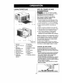
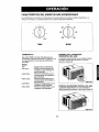
FEATURES
1 15 46
17 9
5 73214
J
16 8 11 1210 13
FIG. 24
USING THE AIR CONDITIONER
To reduce the risk of fire, electric
shock, or injury to persons, read the important
SAFETY instructions section before operating this
appliance
To begin operating the air conditioner after
installation, follow these steps:
1. Plug in the air conditioner. (To prevenl electrical
hazards, do not use an extension cord or an
adapter plug.)
2. Set the exhaust vent to the CLOSE position.
3. Set the TEMP Control to the coolest setting.
4. Set the MODE control at the highest COOL level.
5. Adjust the louvers for comfortable air flow.
6. Once the room has cooled, adjust the TEMP and
Mode Control to the setting you find most
comfortable.
NOTE : If the air conditioner is turned off, wait 3
minutes before restarting. This allows pressure
inside the compressor to equalize. Failure to wait 3
minutes before restarting may cause inefficient
operation.
If you move the TEMP Control to a warmer, then
immediately back to a cooler setting, the unit will
shut off. Wait 3 minutes before restarting.
1. Cabinet
2. Vertical Air
Direction Louvers
3. Horizontal Air
Direction Louvers
4. Front Grille
5. Inlet Grille
6. Air Filter
7. Control Board
8. Power Cord
9. Evaporator Coil
10. Condenser
11. Compressor
12. Base Pan
13. Brace
14. Upper Guide
15. Curtain
16. Vent Control
17. Electric Heater
VENT CONTROL
The Vent Control allows the air conditioner to
either recirculate inside air (CLOSE) or exhaust
air to the outside (OPEN). (FIG. 25)
• The CLOSE position is used when maximum
cooling is desired. It may also be used for air
recirculation without cooling when the air
conditioner is set in the FAN position.
• The OPEN position removes stale air from the
room and exhausts itto the outside. Fresh air is
drawn into the room through your home's
normar air passages.
• The OPEN or CLOSE position can be used with
any fan selection.
PULL OPEN l PUSH CLOSE
FIG. 25
-10-

AIR CONDITIONER FEATURES
The controls featured in this manual are representative of the many models available.
Your model may lookslightly different.
4
2
6
8
COOLER
OFF
LOW
HEAT
FAN FAN
ONLY ONLY
HIGH HIGH
HEAT COOL
LOW
COOL
TEMP MODE
TEMP
Turn the TEMP dial to a higher number for a cooler
room temperature.
Position 5 or 6 is a normal setting for average
conditions.
MODE
OFF :Turns air conditioner off.
FAN ONLY : Fan operation withoutcooling or
heating.
LOWCOOL : Cooling with low fan speed
operation.
HIGHCOOL : Cooling with high fan speed
operation.
LOWHEAT : Heating with low fan speed
operation.
HIGHHEAT : Heating with high fan speed
operation.
HORIZONTAL AIR DIRECTION CONTROL
The horizontal air direction is adjusted by moving
the vedical louvers right and left with your fingertips.
(FIG. 26)
FIG. 26
VERTICAL AIR DIRECTION CONTROL
The vertical air direction is adjusted by moving the
horizontal louvers up and down with your fingertips.
(FIG. 28)
FIG. 27
-11 -

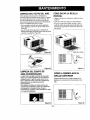
AIR FILTER CLEANING
The Air Filter will become dirty as it removes dust
from the inside air. It should be washed at least
every 2 weeks, ff the Air Filter remains full of dust,
the air flow will decrease and the cooling capacity
will be reduced, possibly damaging the unit.
• Pull the inlel grille forward, grasping both tabs,
then pull out the air filter. (FIG. 28)
• Wash the Air Filter under the faucet with warm
water. Be sure to shake Off all the water before
replacing the filter. (FIG.29)
FIG. 29
AIR CONDITIONER CLEANING
Clean the front grille and inlet grille by wiping with a
cloth dampened in a mild detergent solution.
The cabinet may be washed with mild soap or
detergent and lukewarm water, then polished with
liquid appliance wax.
To ensure continued peak efficiency, the condenser
coils (outdoor side of unit) should be checked
periodically and cleaned if they become clogged
with soot or dirt from the atmosphere, Brush or
vacuum exterior coils to remove debris from fins.
FIG. 30
HOW TO REMOVE THE FRONT
GRILLE
• Open the inlet grille downward,
• Remove the screw securing the Front Grille.
• Push the grille up from the bottom and pull the top
of the grille away from the case to lift the top tabs
out of their slots.
Inlet Grille
_ I \ _ FrootG.,,e
FIG. 31
HOW TO REPLACE THE
FRONT GRILLE
Attach the front grille to the cabinet by inserting the
tabs on the grille into the slots on the front of the
cabinet. Push the grilre in until it snaps into place.
FIG. 32
-12-

BEFORE CALLING FOR SERVICE
Check the following list to be sure a service call is really necessary. A quick reference to this manual may
help you avoid an unneeded service call.
THE AIR CONDITIONER WILL NOT OPERATE
Check if...
Wall plug disconnected.
House fuse blown or circuit breaker tdpped.
MODE selector is OFF position.
Unit was turned off and then on too quickly.
TEMP Control set warmer than room temperature.
Then...
j ushplu9firmlyintowalloutlet
Replacefusewithtimedelaytypeorresetcircuitbreaker.
TurnMODEselectortothedesiredCOOLsetting
Turnunitoffandwait3minutesbeforerestarting.
TurnTEMPControlclockwisetoacoolersetting(highernumber).
AIR FROM UNIT DOES NOT FEEL COLD ENOUGH.
Check if..,
MODE selactor inLOW COOL position.
TEMP Control set too warm (lower number).
Room temperature below 70°F (2t °C).
Temperature sensing tube touching evaporator coil,
located behind front grille.
Then...
Turnselectorto HIGHCOOLposition
TumTEMPControlclockwisetoacoolersetting.
Coolingmaynotoccuruntilroomtemperaturerisesabove70°F(21°C),
Straightentubeawayfromevaporatorcoil.
11"1EAIRCONDITIONERCOOUNG,BUTROOMISTOOWARM-ICEFORMINGONCOOUNGCOILBEHINDFRONTGRILLE
Check if... Then...
Outdoortemporaturebelow70°F(21°C). Todefrostthecoil,setselectortoFANposition.Then,turnTEMPcontrol
counte_se toa warmerset_ng.
Airfiltermaybedirty. Cleanfilter.RefertoMaintenancesecfionofowner'smanual.Todefrost,
setselectortoFANposilJon. I
TEMPControlsettoocoldfornight-timecooling, Todefrostthecoil,setsel,,,e_t,ortoaFANposition.Then,settheMODE
controlaFANpositionor HighCselwiththeTEMPsenroltoawsrmorposition.
THEAIRCONDITIONERCOOLING,BUTROOMISTOOWARM.
Check if...
[ Dirtyairfilter- airrestricted. / Cleanairfilter.RefertoMaintenancesectionofowneCsmanual.
_TEMP Controlsettoowarm, I TumTEMPcontrolclockwisetoa coolersetting(highernumber).
I Frontofunitisblockedbydrapes,blinds,fumtiure, Clearblockageinfrontofunit.
L_etc.Airdistributbnis restricted.
[/_3ors,windows,re_jisters,etc.open.Coldairescapes. Closedoors,windows,re_listers,etc.
IUnit recentlyturnedoninhotroom. Allowadditionaltimetoremove_toredheatfromwalls,ceiling,floor,andlumiture.
THE AIR CONDITIONER TURNS ON AND OFF RAPIDLY.
Check if...
I Outsidetemperatureisextremelyhot.
NOISE WHEN UNIT IS COOLING.
Check if...
_iUndoffanflittingwater-fromthemoistureremovalsystem,
ndowvibration- poorinstallation.
Then...
! SetMODEonHIGHspeedtobringairpastcoolingcoilsfaster. I
Then...
J Thisisnormalwhenhumidityishigh.Closedoors,windows,andrerjistere.Refertoinstallationinstructionsorcheckwithinstaller. I
WATER DRIPPING INSIDE ROOM WHEN UNIT IS COOLING.
Check if.,, Then,.,
I TheairconditlanerisirnpropeityinstalJed. I Tiltairconditionerslighfiytothe outsideto allowwaterdrainage.Referfo
installationinstructionsorcheckwithinstaller. I
WATER DRIPPING OUTSIDE WHEN UNIT IS COOLING.
Check if... Then...
I The uait is remo'_nglar_ quan_s ofn'_sturefromhumidroom. I Thisisn°rmalduringexce_aivelyhureiddays" I
-13-

Room Air Conditioner To order Parts call Toll Free
Model No. 580.72077200 1-800-4-MY-HOME'(I-800-469-4663)
CAUTION: Use the Kenmore part number on all orders, not the illustration number.
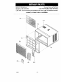
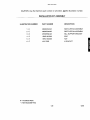
CABINET & FRONT GRILLE ASSEMBLY
3-A
2-A
6-A
4-A 5-A
12/01 - 14 -

580.72077200
CAUTION: Use the Kenmore part number on all orders, not the illustration number.
CABINET & FRONT GRILLE ASSEMBLY
ILLUSTRATION NUMBER PART NUMBER DESCRIPTION
1 - A 3530A10029A FRONT GRILLE
2 - A 3530A10030A INLET GRILLE
3 - A 5231A20004A AIR FILTER ASSEMBLY
4 - A 4758A20003C VANE
5 - A 4758A30008A VANE
6 - A 3091A30005J CABINET ASSEMBLY
7 - A 5210AR3196F UPPER GUIDE
8 - A 3850A20423P LABEL, ENERGY
3828A20292B MANUAL OWNER'S
# = Functional Pans
*= Non-illustrated Pans
- 15 - 12/01

580.72077200
CAUTION: Use the Kenmore part number on all orders, not the illustration number.
CONTROL BOX ASSEMBLY
8-B
9-B
IO-B
12/01 - 16 -

580.72077200
CAUTION: Use the Kenmore part number on all orders, not the illustration number.
CONTROL BOX ASSEMBLY
ILLUSTRATION NUMBER PART NUMBER
DESCRIPTION
1-B 4994A10006A
2-B # 6120AR2359Y
3- B 4H00442N
4- B # 2H00677S
5- B # 2H01127B
6-B # 2H00598F
7-B 4004AR4357A
8- B 3550A30036B
9-B 6631AR3843N
10-B 6631AR2687L
11- B 3721A10018R
12-B 4941A30012C
CONTROLBOX
CAPACITOR
CAPACITOR CLAMP
POWER CORD ASSEMBLY
THERMOSTAT
ROTARY SWITCH
HOLDER PC
COVER, CONTROLBOX
CONNECTORASSEMBLY
CONNECTORASSEMBLY
CONTROLPANEL
KNOB ASSEMBLY
# = Functional Parts
* = Non-illustrated Parts
- 17 - 12/01

580.72077200
CAUTION: Use the Kenmore part number on all orders, not the illustration number.
AIR HANDLING & CYCLE PARTS
2-C 12-C
14-C
11-C 9-C
10-C
19-C
13-C
18-C
12/01 - 18 -

580.72077200
CAUTION: Use the Kenmore part number on all orders, not the illustration number.
AIR HANDLING & CYCLE PARTS
ILLUSTRATION NUMBER PART NUMBER
DESCRIPTION
1 - C 3041A30005D BASE PAN WELD ASSEMBLY
2 - C 5238A10001C AIR GUIDE
3 - C 5301A20013A HEAT ASSEMBLY
4 - C 4901A30001A VENTILATION DAMPER
5 - C 4960A20002A MOTOR MOUNT
6- C # 4681A20027A MOTOR ASSEMBLY
7 - C 3072A10001A SCROLL
8 - C # 5901A10005B FAN ASSEMBLY, BLOWER
9- C # 5900AR1167B FAN
10 - C 3H02932B CLAMP SPRING
11 - C 4998A10001A SHROUD
12 - C 4800A30001A BRACE
13-C # 5421A20036C EVAPORATOR ASSEMBLY
14-C # 5403A20024B CONDENSER ASSEMBLY
15 - C 4H02023A DRAIN RUBBER
16 - C 4H01029D WASHER RUBBER
17 - C 3H02773A ORAIN PIPE
18 - C 4790A10008A BARRIER
19 - C 3530A20009B GRILLE ASSEMBLY, REAR
# = Functional Parts
* = Non-illustrated Parts
- 19- 12/01

580.72077200
CAUTION: Use the Kenmore part number on all orders, not the illustration number.
COMPRESSOR PARTS
9-D
8-D ®
7-D _ 12-D
6o
2-D
4-D (
3-D
1-D
11-D
12/01 - 20 -

580.72077200
CAUTION: Use the Kenmore part number on all orders, not the illustration number.
COMPRESSOR PARTS
ILLUSTRATION NUMBER PART NUMBER
DESCRIPTION
1-D 5040AR4195A
2-D # 2520UAEC2DA
3-D 4810AR4155A
4- D 1NHA0801206
5- D 4986U-L001G
6- D # 6750U-L005A
7- D 3550U-L004A
8-D 4H01058A
9- D 4H00947A
10- D 5210A20119D
11- D 5211A20130A
12-D 5211A20131H
13-D 5211AR7059Y
14- D 5211A30260D
15-D 5851A30001G
ISOLATOR, COMP
COMPRESSOR
BRACKET, WASHER
HEXAGON NUTS
GASKET
OVERLOAD PROTECTOR
TERMINAL COVER
GASKET NUT
TERMINAL COVER NUT
TUBE ASSEMBLY DISCHARGE
TUBE ASSEMBLY SUCTION
TUBE ASSEMBLY EVAPORATOR
TUBE ASSEMBLY CONNECTOR
TUBE ASSEMBLY CAPILLARY
DRIER ASSEMBLY
# = Functional Parts
* = Non-illustrated Parts
- 21 - 12/01

580.72077200
CAUTION: Use the Kenmore part number on all orders, not the illustration number.
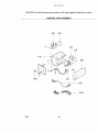
INSTALLATION KIT ASSEMBLY
2-E
12/01 - 22 -

580.72077200
CAUTION: Use the Kenmore part number on all orders, not the illustration number.
INSTALLATION KIT ASSEMBLY
ILLUSTRATION NUMBER PART NUMBER
DESCRIPTION
1 - E 4959AR3402A SIDE CURTAIN ASSEMBLY
2 - E 4959AR3402B SIDE CURTAIN ASSEMBLY
3 - E 4810AR3240A SILL SUPPORT BRACKET
4 - E 1BHD1004006 BOLT
5 - E 1NHC1000006 NUT
6 - E 4H01785B L BRACKET
# = Functional Parts
* = Non-illustrated Parts
- 23 - 12/01

INDICEDEMATERIAS............................. 24
GARANTfA ................................................ 24
SEGURIDAD .............................................. 25
Impodantesinstruccionesdeseguridad.....25
REQUERIMIENTOS ELIeCTRICOS .........26
INSTALACI(_N ........................................... 27
Requerimientos para instalaci6n .......... 27
Installaci6n ............................................ 28
C6mo instalarlo ..................................... 28
C6mo sacar el equipo de aire
acondicionado de la ventana ................. 30
OPERACII_N .............................................. 31
C6mo y por qu_ ..................................... 31
Sonidos normales .................................. 31
Capacidad y tiempo de funcionamiento .-.31
Caracterfsticas ..................................... 32
Uso del equipo de aire acondicionado .,32
Despliegue ............................................ 33
MANTENIMIENTO .................................... 34
Limpieza del filtro del aire ...................... 34
Limpiezadelequipodeaireacondicionado.-..34
C6mo sacar la rejilla frontal ................... 34
C6mo a reemplaza el grille anterior ...... 34
CORRECCI(_N DE FALLAS ...................... 35
AntesdeLlamarparaservicio...................... 35
LISTA DE PARTES ............................. 14~23
PARA PEDIR SERVICIO .......Cubierta Trasera
GARANTiA DE UN ANO POR EL
EQUIPO DE A|RE ACONDICIONADO
DE HABITACION
Durante un aSo completo a partir de la fecha de
compra, si este equipo de aire acondicionado recibe
mantenimiento y se utiliza para el enfriamiento
normal de habitaci6n segi)n las instrucciones
indicadas en este manual del propietario, Sears
reparara gratuitamente este equipo de aire
acondicionado, si tiene algL_ndefecto en materiales
o fabricacibn.
GARANT[A TOTAL DE ClNCO ANOS
POR E_-SISTEMA DE REFRIGERACION
HERMETICAMENTE SELLADO
Durante cinco aSos a partir de la fecha de compra,
si este equipo de aire acondicionado recibe
mantenimiento y se utiliza para el enfriamiento
normal de habitaci6n seg_n las instrucciones
indicadas en este manual del propietario, Sears
reparar_ gratuitamente el sistema de refrigeraci6n
herm(_ticamente sellado (que consiste en el agente
refrigerante, los tubos de conexibn y el compresor),
si tiene alg_n defecto en materiales o fabricaci6n.
EL SERVICIO DE GARANT|A EST'. A SU
DISPOSICION CON SOLO PONERSE EN
CONTACTO El. CENTRO DE SEARS AL
1-800-4-MY-HOME ®
La proteccion de garantia cubre unicamente a los
equipos de aire acondicionado usados para uso
domestico y no para uso comercial.
Esta garantfa s61o tiene validez mientras el producto
se este usando en los Estados Unidos.
Esta garantia le da derechos legales especfficos y
usted puede tener otros derechos que varfan de
estado en estado.
Sears, Roebuck and Co., D/817WA,
Hoffman Estates, IL 60179 U.S.A.
- 24 -

IMPORTANTES INSTRUCCIONES DE SEGURIDAD
Las siguientes instrucoiones de seguridad le indicaran c6mo usar su equipo de aire acondicionado de
habitaci6n para evitar daSos para usted mismo y para su EQUIPO DE AIRE ACONDICIONADO.
_POR SU SEGURIDAD
No almacene ni use gasolina u otros vapores y
liquidos inflamables cerca de 6ste o cualquier otro
electrodomestico. Lea las etiquetas de los
productos para vet si contienen advertencias sobre
el caracter inflamable de los mismos y otras
advertencias.
PARA PREVENIR ACClDENTES
Para reducir el riesgo de incendios, descargas
el_ctricas o lesiones personales al usar su equipo
de aire acondicionado, tome las precauciones
basicas, entre las que estdn las siguientes:
• Aseg0rese de que la alimentaci6n electrica sea la
apropiada para el modelo que usted ha elegido.
• Si el equipo de aire acondicionado debe instalarse
en una ventana, a usted probablemente le
conviene limpiar primero ambos lados del vidrio.
Si la ventana es de1tipo de tres paneles con un
panel incluido de pantalla, le conviene sacar la
ventana completamente antes de la instalaci6n.
• Aseg0rese de que el equipo de aire
acondicionado ha sido instalado correctamente y
con seguridad seg0n se seSala en las
instrucciones separadas de instalaci6n que vienen
en este manual. Conserve este manual y las
instrucciones de instalaci6n para usarlos
posiblemente en el futuro al sacar o volver a
instalar esta unidad.
• Utilice guantes al manejar el equipo de aire
acondicionado. Tenga cuidado para evitar cortadas
con las afiladas aletas meta.licas que se hallan en los
serpentines frontales y posteriores.
INFORMACI(3N ELECTRICA
En la plata de serie del fabricante se indica cual es
la capacidad el_,ctdcanominal completa de sunuevo
equipo de aire acondicionade para hab'rtaci6n.Consulte
esta placa cuando vaya averificar los requerimientos
el_tricos.
• Aseg0rese de que el equipa de aireacondicionado
tenga unaconexibn correcta atierra. Para reduciral
minimo los riesgos de descargas electdcase incendio,
es importante conectar el equipa correctamente a tierra.
Elcord6n de alimentaci6n el_tdca est_equipado con
un enchufe de tres espigascon conexibn atierra para
protegerle contra desgos de descargas el_'ctdcas.
• Su equipo de aire acondicionado debe enchufarse en
unatoma de corriente de pared que tenga una conexi6n
correcta atierra. Si la toma de corriente de paredque
ustedpiensa usarno est& conectada correctamente a
tiena ono est_ protegida con un fusible de acci6n
retardada o conun interruptorde circuito,haga que un
e_actricistacarr_cadoleinstalelatoma decorriente de
pareden forma correct&
• Nopongaafuncionar el eduipo deaim acondicionado
con unacubiertaprotectoraexteriorencima.Estopedria
ocasionarde_os mec,_nicosdentrodelaire
acondicionado.
• No use un cablede extensi6n ni un enchufe
adaptador.
_ Evitelospeligrosdeincendiosy
descargaselectricas.Nouseuncablede extensi6nni un
enchufeadaptador.No elimineningunade lasespigas
delenchufedelcord6nde alimentaci6nelL,ctdca.
Toms decorriente
de paredcon En ninguna
conexi6natierra, circunstancia code,
extraiga o intente
eliminar laespiga de
conexi6n a tierra de
este enchufe.
]
Cord6ndealimentad6nel_t_a con
enchufedeiresespgasconconexJbn
\
atierra.
IDEAS PARA AHORRAR ENERGfA
• La capacidad del equipo de aire acondioionado
debe corresponder al tama_o de la habitacibn
para el funcionamiento eficiente y satisfactorio del
equipo.
• Insta]e el equipo de aire acondieionado de
habitaci6n en el lade sombreado de su hogar, Una
ventana orientada hacia el norte es la mejor
porque tiene sombra la mayor parte del dfa.
• No bloquee el flujo de aire hacia el interior con
persianas, cortinas o muebles; o la parte de
afuera con arbustos, paredes u otras
construcciones.
• Cierre el regulador de tiro de la chimenea, las
rejillas de calefaccibn del piso y la pared, de tal
mode que el aire frio no se escape ni por la
chimenea ni per los conductos.
• Mantenga las persianas y las cortinas de otras
ventanas cerradas durante la parte mds soleada
del dia.
• Limpie el filtro del aire como se recomienda en la
secci6n "MANTENIMIENTO" de este manual.
• El aislamiento correcto y las juntas herm6ticas en
puertas y ventanas en su hogar le ayudar_.n a
mantener el aire caliente afuera y el aire fifo
adentro.
• AI darle sombra externamente a la casa con
drboles, plantas o toldos ayudar& a reducir la
carga de trabajo del equipo de aire acondicionado.
• Opere los aparatos que produeen calor como, por
ejemplo, homos, lavadoras, secadoras y
lavaplatos durante la parte mds fria del dfa.
- 25 -

RESPETE TODOS LOS C()DIGOS Y
REGLAMENTOS.
BAJO NINGUNA CIRCUNSTANCIA CORTE,
QUITE O EVITE EL use DE LA CONEXION
A TIERRA DE ESTA CLAVIJA,
ESTE APARATO NECESITA SER
CONECTADO A TIERRA.
Se requiere una alimentaci6n electrica CA,
adecuadamente cenectada a tierra con un
fusible de15A, de 60 Hz y de115 V. Se
recomienda un fusible de retardo o un
disyuntor de circuito que alimente solamente a
este aparato.
NO USE CABLE ELECTRICO DE
EXTENSION.
MI_TODO RECOMENDADO DE CONEXI(_N A
TIERRA
Per su propia seguridad este aparato debe
conectarse a tierra. Este aparato viene
equipado con un cable de alimentaci6n y una
clavija de tres terminales. Para reducir al
maximo el peligro de cheque el_ctrico, el cable
debe estar conectado a una conexi6n de pared
con conexion a tierra, y esta conexi6n debe
hacerse de acuerdo con la _ltima edici6n del
Codigo Electrico Nacional (ANSI/NFPA 70), asf
come con los c6diges y reglamentos locales. Si
no existe una conexi6n de pared adecuada, el
cliente tiene la responsabilidad y la obligaci6n
de mandar instalar, con un electricista
calificado, una conexi6n de pared adecuada de
tres terminales con conexi6n a tierra.
A ADVERTENCIA
Peligrode chequeel6ctrico
Conecteen unaconexi6nde paredde3 terminales
Noquitela terminalde conexi6na tierra
No useadaptadores
No usecableelectricode extensi6n
Si no sesiguenestasinstrucciones,puede
ocasionarsela muerte,un incendioo uncheque
electnco.
Cable de_
alimentaci6n con
clavija dotada de
conexion a tierra
de 3 terminales.
Toma de corriente _'_'_
de pared con :111_ !
conexi6n a tierra _ I
F __cT_rmii_erra.
Bajo ninguna
circunstancia corte, quite o
evite el uso de la conexi6n
a tierra de esta clavija.
- 26 -

REQUERIMI.ENTOS PARA
INSTALACION
Su equipo de aire acondicionado se instalar_ en ventanas
est&ndar de doble panel con anchos de abertura libre de
559 mm a915 mm (22 a 36 pulgadas). (Figura 1)
Si suequipo de aire acondicionado es instalado por la
pared,el tamano del agujero en lapared tiene que medir
15 23/32r'X24 V4"(sinla guia superior).
El marco inferiordebe abrirse Iosuficiente para permitir
unaabertura vertical libre de 381 mm (15pulgadas).
Las rejillas desviadoras laterales y la parte posterior del
equipo de aire acondicionado deben tener un espacio
libre de aire para permitir suficiente flujo de aire atrav6s
del condensador para asi eliminar el calor. La parte
posterior de la unidad debe quedar al aire libre, no dentro
de un edificio o garaje.
_L ¢==o _? Banda
I 22"to 36"
I _1i" min, Replsa EL/--Ventana
"_- ", = Antepecho
_"_ _}_- Exterior
Paredinterior" '; Figuraj 1
SERVICIO ELECTRICO
Comprueba cuales la alimentaci6n el6ctricaqueIlegaa
su domicilio,La alimentaci6n el6etdca disponible debeser
la misma que semuestra en la placa del fabricante de la
unidad (que se halla en ellado derecho del gabinefe de
corriente alterna).
Todos los modelosestdn equipados con un enchufede
tres espigas para suministrar un servicio correcto y una
conexi6n a tierra segura y positiva. No cambie el enchufe
de ningunaforma. No use un enchufe adaptador. Si su
toma de corriente de pared actual no puede usarse con el
enchufe del eqoipo, Ilamea un electricista calificado para
queefect_e las correcciones necasarias.
CONSERVE LACAJA y este MANUAL DEL
PROPIETARIO para que le sirva como referencia en el
futuro. La caja es la mejor manera de conservar la unidad
durante el inviemo o cuando no est,. en uso.
Para evitarel riesgode lesiones personales,danos a su
propiedad,o danosal producto debido alpeso de este
equipo y los filos a que seran expuestos:
• El aire acondicionadodel quese habla en este manual
afirma peligro de peso excesivo.
Dos o mas personas serequiem para mover e instalar
la unidad. Para evitar heridas o agotamlento,use
tecnicasapropiadaspara levntary mover la unidad.
• Cuidadosamenteinspeccione el lugar donde el aire
acondicionadosera puesto. Asegurese que e[ [ugar
sostangael peso de la unidad sobre un periodode
tiempo prolongado.
• Mantengasu aire acondicionadocon cuidado. Use
_._/antesprotectores cuando levante o mueva launidad.
ITElas aletas filosas de metal en el serpentin
delanteroy de atras.
• Asegurese que el aireacondicionadono sacaiga
durante la instalacion.
INSTALACI(_N PIEZAS DE MONTAJE
iTEM NOMBRE DE LA PIEZA
A PANEL DE GUiA
B SOPORTE DE ANTEPECHO
C PERNO
D TUERCA
E TORNILLO: 25/64"
F TORNILLO: 5/8"
G TORNILLO: 5/8"
H CINTA DE ESPUMA
I CINTA DE ESPUMA
J SOPORTE DE CERRADURA
CANTIDAD
2
2
2
2
13
3
5
1
1
1
HERRAMIENTAS REQUERIDAS
• Guantes apretados
• Destornillador normal
• Destorniltador Phillips
• Pinsas
• Cuchillo filoso
• Llave inglesa o Ilave abierta de 3/8"
• Llave hexagonal de cubo y trinquete de 1/4
de pulgada
• Cinta para medir
• Taladro electrico
• Broca de taladro de 1/4"
- 27 -

INSTALACION
EscolaunlugarquelepermitaIlevarel aire frio alareaque
desea. Lasventanasque sousen parala instalaci0ndeben
tener taresistenciasufieientapara soportarel pesodel
equipode aireacondicionado.Unabuenainstalacioncon
atancionespeciala la correctaposicionde la unidad
disminuiralaprobabilidaddeque seanecesarioefectuar
reparaciones.
Cuandosedeseaenfriarm#=sde unahabitacion,la
instalaciones muyimpodantesi el aireacondicionadoesta
bloquedoporun marcode lacontraventanayeael paso19
en lap_,gina8antesdecomenzarla instalacion.Paraenfriar
sushabitaciones,el aire fdo debedesplazarsedesdeel
equipode aireacondicionadoen unatrayectoriarecta.
CC)MO INSTALARLO
_1 Saque los tornillos que aseguran el gabinete
en ambos lados yen la parte posterior.
Figure3
F_ Deslice la unidad sacdndola de su gabinete
agarrando el asa del recipiente de la base y tirando
de ella hacia delante mientras sostiene el gabinete.
Figure4
!_ Corte la cinta de espuma (ITEM I) a la
extension apropiada.
Despegue el refuerzo y peguelo en el lado de abajo
del marco de la ventana.
IL_ Inserte los paneles de guia ({TEM A) en la guia
superior y las guias de marco del equipo de aire
acondicionado. Sujete las cortinas en la unidad con
los tornillos ({TEM E).
iTEM E
*=
{TEM E
l_'_ Abra la ventana, Marque una linea en el centro
de la repisa de le ventana (o en la pesici6n deseada
del equipo de aire acendicionado). Coloque
caidadosamente el gabinete ee la repisa de la ventana
y alinee la marca central en laparte frontal inferior con
la linea central marcade en la repisa de la ventana.
;
su_ri°r_; ;Guia RaesPiba_aelaventana
Figura7
D Tire del marco inferior de laventana hacia abajo
detr_.sde la guia superior hastaque se encuentre la gu{a
con el marco.
NOTA: No tire delmarcode laventena tan haciaabajo
que quede restringido el movimiento del panel guia.
Marco de la ventana
iTEM H ( a superior
iTEMA
Figure 8
H Monte sin apretar el soporte de antepecho
usando las piezas indicadas en la Figura 9.
INTERIOR _ f_ EXTERIOR
" ,L'B
/ ITEM D
{TEM C Rgura 9
- 28 -

f_ Seleccione la posici6n en la que colocar_, el sopede
de antepecho cerca del punto m_s externo en eq
antepecho (Figura 10). Fije el soporte de antepeche al
orificio del carril del gabinete en relaci6n con la posici6n
seleccionada usando el tornillo (iTEM E).
flEME _)
Guia irlferior
## ,;
Gabinele
EXTERIOR
INTERIOR Figura10
_1 Coloqueelsoportede antepechoconel gabineteen la
posicionseleccionadadel antepechode ventana(Figura 10).
_i_EI gabinete debe instalarse con una inclinacion muy
ligera (cerca de 1/4 pulgada, 6.35 ram) hacia abajo y
hacia fuera (Figura 11).
Ajuste el perno y latuerca del soporte de antepecho para
equilibrar el gabinete.
q
_1 Fijeel soporte de antepecho al orilicio del carril del
gabinete en relaci6n con la posici6n seleccienada usande
el tornillo (iTEM F) (Figura 12).
Carril de
marco
{TEM B
Guia masbaja
iTEM F
Figura 12
_"_ Fije cada panel guia completamente acada marco
de la ventana usando tornillos ({TEM G). (Figura 13)
iTEM G
Figura13
_] Corte la cinta de espuma para quetenga la Iongitud
correcta e ins_rtela entre el marco superior de la ventana
y el marco inferior de la ventana. (Figura 14)
_ {TEM G
Figura14
[] DRENAJE
Primero, aseg0rese de insertar el tubo de drenaje en el
recipiente de base antes de la instalaci6n. El equipo de
aireacondicionado debe instalarse con una ligera
inclinaci6n hacia laparte exterior para permitir el drenaje
de1agua. PorIo general et equipo de aire acondicionado
puede drenar el agua condensada a traves de la tubefia
de drenaje. (Figura 15)
_r, PARTE POSTERIOR
TUBO DE !_ DEL RECIP!ENTE
DI_ENAJE DE 6ASE
#ARTE INF£RIOR DEL
__sE Figura15
[] Deslice el chasis meti_ndolo dentro del gabinete.
(Figura 16)
CUIDADO: Para garantizar la seguridad, vuelva ainstalar
los tornillos en los lados delgabinete.
j Cord6n de
alimentaci6n electrica
T6rnillo Rgura16
_'_ Despu_s de a instalarla unidad en el
volver
gabinete, habr& un espacio libre entre la cara inferior de
la unidad y el antepecho de la ventana. Use lacinta de
espuma (ITEM H) provista para cubrir esta abertura.
Rgura17
D_Se debe instalar el asa antes de montar el panel
decorativo. Antes de usar la caractedstica de ventilaci6n,
haga un kit de ventilaci6n, primero, tire de la parle A
hasta la Iineahorizontal con la parte B.
ParteB
_Parte A _,/_ _
Rgura 18
- 29 -

_] INSTALACI(_N FRONTAL
Instale la rejilla frontal con el gabinete de la
siguiente manera:
• Tire de la rejilla frontal hacia debajo desde la parte
superior del gabinete
• Empuje las puntas de la rejiUa frontal hacia el
gabinete para insertar las leng,etas de la rejilla
dentro del gabinete.
• Abra la rejilla de entrada
• Apriete el tornUlo (ITEM E) a traves de la rejilla
frontal fi a.ndolo al recipiente de base
• Cierre la re a de entrada
INSTALACION FRONTAL
Figura19
ITEM E
INSTALACION FRONTAL
Figura20
INSTALACION FRONTAL
Figura 21
_]Sl ELACONDICIONADORDE AIREESTA
BLOOUEADOPOREL MARCODE LACONTRAVENTANA
• Si lacontraventana interfiere, fije unlist6n de madera de
2" de ancho al alf_izar interior de la ventana, que
atraviese la anchura total del alf_.izar.El listbn de
madera debe set suficientemente grueso para levantar
la altura del alfdizar de laventana de tal manera que la
unidadpueda ser instaladasin la intederencia del marco
de lacontraventana.Vea la Figura 22.
La parle superior del liet6nde madera debe ser
aproximadamente 3/4" masalto queel marco de la
contraventana oel listen de madera (fuera de la casa)
para queel vapor emanado de launidad pueda drenar
adecuadamente hacia el exterior.
• fnstaleun segundolist6nde madera(deaproximadamente
6' de largoy 1" deanchoy del mismogrosordelprimer
listen)en el centre delalfeizarexteriorniveladocon la
parle posteriordel alfeizarinterior Atomillelos soportesL
entre la faja Esto levantarael soporteL comese muestra
en laFigura22
1 1/2' rain
(38mm)
FRANJA DE MADERA _ ,_ 314 PULG
MONTADA SOBRE _ _ ! DE SEPARACION
LA PARTE SUPERIOR '_ I
DEL DESCANS_
_NTERIOR _ VENTANA DE
HOJADOSLE
ANTEPECHO
INTERIOR
ANTEPECHO
ERROR
Figura22
La ELIMINACIONDEla VENTANA
•Apagueelacondicionadoraereo.
• Quiteelgrilleanterior.VeaCOMOA REEMPLAZAELGRILLE
ANTERIOR.Refierasea p_gina34.
• Destomilleel tomi!lodelladequeustedinstal6enelPaso15.
• Deslieeelaeondicionadoraereofueradelgabinete.TENGA
CUIDADOnoAla GOTATengaenIofirmementelamanera
enteraquedeslizafuera Unavezquitade,1opusoseguridad
fueradelamanera
• QuiteelparentesisLdel marcodeventanay elsellodebanda
deentreelwindows
• Destornillelascortinasdelladedelmarcodeventana.
D6blelosapoyanalosladesdelgabinete.
• Quiteeltomilloconectargabinetealalf_izalinterior.Tengacuidado
noapermitioquegabinetefallaraunaveztomillossequitan.
• Quitegabinetedeabrirdeventana.
• Coloqueel acendicionadora6reoenelgabinete.Vuelvaa
instalarlostornillosdelladey GrilleAnterior.
• Coloquela unidady todaferreteriadelaasambleaen el
cart6na_reodelenviodelacondicionador,yen la tiendaen
limpia,seeael lugar.
•El aire acondicionado del que se hablaen este
manual afirma peligro de peso excesivo.
Dos o mas personas se requiem para mover e
instalar la unidad. Para evitar heddas o
agotamlento, use teenicas apropiadas para
levntar y mover launidad.
• AImanejar la unidad, tenga ouidado para evitar
eortarsecon lasaledas met_.licasafiladas que
estan en los serpentines frontal y posterior.
• Asegurese que el aire acondicionado no se caiga
durante la instalacion.
- 30 -

COMO YPOR QUE
Su equipo de aire acondicionado de habitacion
brinda las siguientes funciones para hacer que la
vida en climas calidos sea mas confortable:
• Enfrfa y hace circular el aire por la habitaci6n
• Disminuye la humedad eliminando la humedad
exoesiva.
• Filtra el polvo, el sucio y algunas impurezas
transportadas en el aire del clima veraniego.
El equipo de aire acondicionado realiza estas
funciones haciendo pasar el aire del medio
ambiente a trav_s de un filtro que atrapa las
particulas de polvo y sucio. El aire pasa entonces
por un serpentfn de enfriamiento que refrigera el
aire y elimina el exceso de humedad. El mismo aire
regresa entonces al enfriador, secador y limpiador
del aire del ambiente. La humedad extraida del aire
ambiente es Ilevada al exterior y evaporada.
Su aire acondicionado esta diseSado para operar y
suministrar una enorme potencia de enfriamiento.
SONIDOS NORMALES Figura23
Ademds de los sonidos regulares del motor del
ventilador y el compresor que salen de su equipo
de aire acondicionado, usted escuchar_ de vez en
cuando un sonido met&lico. Este sonido es
producido por la humedad que es recogida del aire
en el ambiente yes lanzada contra el ventilador del
equipo de aire acondicionado. Esto es algo normal
que no debe ser motivo de preocupaci6n. De igual
modo, no se alarme si usted escucha un ligero
sonido de silbido o borboteo proveniente de su
equipo de aire acondicionado despu6s que Io
apaga. Estos son ruidos normales del refrigerante.
CAPACIDAD Y TIEMPO DE
FUNCIONAMIENTO
AIdecidircualdedeserlacomodideddeseadaparael_reaque
ustedquiereenf_r, esimportantedeterminareltama_ocorrecto
dela unidad.Unaunidadpequenanotendralacapacidadpara
enfriar,dejandola areacolurosa.Eltama_oadecuadees
determinadeporel nt]merodemetroscuadradesquetieneel
areaquesedeseaenffiar,asfcomoporlatemperaturainteriory
exteriory porlahumedad.Unaunidaddemasiadegrandesi
ealria,peronodeshumedeea,dejandolaareafriay humeda.
Siernprequelacargat_rmicadelventiladoresteporendrnade
Ionormal,el equipodeaireaceadicionadedebefunaonarmas
tiempoparamantenerlatemperaturadeseadaqueustedha
seleccionade.Bajoeandicionesde unacargaterrnicamuy
pesada,puedeserneeasanoqueelequipodeaire
acondidonadefuncioneco_stantementeparamantenerla
temperaturadeseada.
Enocasiones,elusode MEDFANparahacerdrcularelairepor
lahabitaci6nhacequeelambienteseamasconfortableaun
cuandoelequiponoesteenfriandeelaire.Mientrasmastiempo
y conmayorfrecuenciafuncioneelequipodeaire
acondicionade,maselectricidadconsumiray mayoresseranlos
costosdesuuso.
Compresor
El moderno compresor de gran
eficiencia puede producir un ruido
agudo de murmullo o un ruido de
pulsacion que viene y se va.
la
unidad
La unidad puede vibrar y
hacer ruido debido a la
deficiente construcci6n
Ventilador
Usted puede
escuehar el
movimiento del
aire proveniente
del ventilador
Usted puede escuchar
gotas de agua que caen
sobre el condensador
causando un sonido
met&lice o un sonido de
chasquido.
Figura 23
- 31 -

CARACTERISTICAS
i
15 46
i
5 7 14
17 9 16 8
11 1210 13
Figura 24
1. Gabinete
2. Deflector vertical de
aire
3. Deflectors
horizontal de aire
4. Grille anterior
5. Rejilla de entrada
6. Filtro del aire
7. Tablero de control.
8. Cordbn de
alimentacion
el_ctrica
9. Evaporador
10. Condensador
11. Compresor
12. Recipiente de base
13. Puetal
14. Guia superior
15. Cortina
16. Descargar el
Control
17. Calentador electrico
USO DEL EQUIPO DE AIRE
ACONDICIONADO
_Para reducir el riesgo de incendio,
_ectrica o lesiones personales, lea las
IMPORTANTES INSTRUCCIONES DE
SEGURIDAD antes de operar este aparato.
Para comenzar a utilizar el equipo de aire
acondicionado, siga estos pasos:
1. Enchufe el equipo de aire acondicionado. (Para
prevenir riesgos de descargas electricas, no use
un cable de extensi6n ni un enchufe adaptador.)
2. Ajuste el extractor de aire en la posicibn CLOSE.
3. Ajuste el control de MODE al mas alto nivel
fresco.
4. Ajuste el control del ventilador al m_i.salto nivel.
5. Ajuste las rejillas desviadoras para Iograr un flujo
confortable de aire con la leng_leta de control.
6. Una vez que la habitaci6n se haya enfriado,
ajuste el control de temperatura TEMP a la
graduaci6n que usted considere m_ls confortable.
NOTA: Si se apaga el aire acondicionado, espere 3
minutos antes de volver a encenderlo. Esto permite
que se estabilice la presibn dentro del compresor.
Si no sigue estas instrocciones, el equipo podria
funcionar con poca eficiencia.
Si usted mueve el TEMP el control a un warmer,
entonces inmediatamente espalda a una colocaci6n
m&s fresca, la unidad apagara. Espere 3 minutos.
CONTROL DE VENTILACI6N
El controldeven_laci6npermitequeelequipodeaire
acondicionadohagarecircularel aireenelinteriorde la
habitaci6n(CLOSE)o saqueel aire haciaelexterior(OPEN).
(Figura25)
• La posici6nCLOSE sirvecuando sedeseaun enfriarniento
m_ximo.Tambi_npuedeusarseparahacerrecircularel
airesinenfriarla habitaci6ncuandoelequipodeaire
acondicionadoseajustaen la posici6nFAN.
• La posici6nOPENextrae elaireestancadodelahabitaciSn
y Ioexpulsahaciafuera.Elaire frescoes Ilevadohaciael
interiorde lahabitaci6natrav_sdelos pasajesnormalesde
aireque sehallanen loshogares.
• LaposicibnOPEN o CLOSEpuede usarseconcualquier
selecci6ndeventilador.
igura 25
PULL OPEN/PUSH CLOSE'
(TIRAR PARA ABRIR / EMPUJAR PARA CERRAR)
- 32 -

CARACTERiSTICASDEL EQUIPODE AIREACONDICIONADO
Los controles que se explican en este manual son representativos de muchos modelos disponibles a la
venta en el mercado. Su modelo puede tener un aspecto ligeramente diferente.
4
2
OFF
6 FAN FAN
_7 8 ONLY ONLYLOW I__HOI LOW
HEAT COOL
HI GH
HEAT COOL
C_U_R
TEMP MODE
TERMOSTATO
Gire el dial TEMP al mimero mas alto para una
temperatura ambiente mds fresca. La posiciSn 5 o 6
es una graduacibn normal para las condiciones
promedios.
MODO
OFF
FAN ONLY
LOW COOL
HIGH COOL
LOW HEAT
HIGH HEAT
: Apaga el aire acondicionado.
: Permite el funcionamiento del
ventilador a baja velocidad sin
enfriar (calentar).
: Permite el enfriamiento con el
funcionamiento de[ ventilador a
baja velocidad,
: Permite el enfriamiento con el
funcionamiento del ventilador a
alia velocidad.
: Permite el calentamiento con el
ventilador a baja velocidad.
: Permite el calentamiento con el
ventilador a alia velocidad.
CONTROL DE LA DIRECCION
HORIZONTAL DEL AIRE
La direcci6n horizontal del aire es ajustada rotando
la palanca vertical hacia la derecha o hacia la
izquierda. (Figura 26)
igura 26
CONTROL DE DIRECCI(_N VERTICAL DEL AIRE
La direccibnverticaldel aire se ajusta moviendo la
rejilla horizontalhacia delante o hacia atras.(Figura 28)
Figura 27
- 33 -

LIMPIEZA DEL FILTRO DEL AIRE
Elfiltro del aire se ira ensuciando a medida que va
atrapando el polvo proveniente del aire interior. Es preciso
lavarel filtro delaire al menos cadados semanas. Si el
filtro del aire permanece Ilenode polvo,el flujo de aire
disminuiray sereducira la capacidadde enfriamiento del
equipo, con posibles dafios para la unidad.
• Tire de la rejilla de entrada hacia delante agarrando
ambas lengeetasy tire de1filtro del aire hastesacarlo.
(Figura 28)
• Lave el filtro del aireen agua tibia a. Aseg6rese de
eliminar toda el agua sacudiendo elfiltro antes de volver
a ponerlo en su posici6n. (Figure 29)
Figura 28
Figura 29
LIMPIEZA DEL EQUIPO DE
AIRE ACONDICIONADO
La rejillafrontal y la rejiUade entrada del aire pueden
lavarse con un paso humedecido en una soluci6n de
detergente suave. El gabinete puede lavarse con un
jab6n o detergente suave y agua tibia, seguidamente
puede pulirse con cera Ifquida especial para
electrodom_sticos.
Para asegurar una eficiencia m_ima continua, los
serpentines del condensador (el lado de la unidad que
est& expuesto a la intemperie) deben revisarse
peri6dicamente y limpiarse si est_n obstruidos con hollfn
o con sucio de la atm6sfera.
Figura 30
COMO SACAR LA REJILLA
FRONTAL
• Saque el tornillo que mantiene la rejilla frontal en
posici6n.
• Quite el tornillo que asegura le reja delantera.
• Empuje la rejilla hacia arriba de abajo y jale la
parte de arriba de la rejilla lejos de la base pare
levantar las ienguetas de arriba hacia afuera de
las ranuras.
Rejilla de entrada
Figura 31
COMO A REEMPLAZA EL
GRILLE ANTERIOR
Pegue el panel frontal a la caja insertando los
fijadores en el panel adentro las aberturas de la
caJa.
Figura 32
-34-

ANTES DE LLAMAR PARA SERVICIO
Cheque ]a siguiente lista pare asegurarse si en realidad es necesario Ilamar pare servicio. Una referencia rapida a
este manual puede evitar una Ilamada para servicio innecesaria.
EL EQUIPO DE AIRE ACONDICIONADO NO FUNCIONA.
I Elenchufenoestaconectadoenlatomedecorriectedepared
Elfusibleestaquemadeoelinterruptordecircuitose hadisparade.
ELselectorde_ventLladorPOWERestaenla posici6ndeOFF
I Launidadseapagoy sevolvi6aencenderdemasiadorapide
ElconlroldetemperaturaTEMPseajust6mascalidoquela
temperatureambienle
Conecteelenchufefirmemen_eenlatomadecomentedepared
Reemplacee]fusibledanadeconunfusibledeaccideretardedeo rea]usteel
interruptordecircuito
PongaelsolectorenLaposicidedeCOOL.
Alustelaunidedy espere3minutosantesdevolveraencendelta
AjusteelcontroldeTEMPERATURAaunnL_meromasbajo
EL AIRE DE LA UNIDAD NO SALE BASTANTE FR|O.
D_sminuya_aVELOCIDADDELVENTILADOR.
Co_os elcor_ deTEMPERA_IRAenunnt)merornasa_io
Latemperaturaambienteesta pardebajodelos70° F (21°C)
Eltubosensordetemparaturaestatocandoelserpentinevaporador
queestasduadodetr_sde]filtrode]aire.
Gireel selectora unaposici6nHIGHCOOL,
Gireelcontroldetem_ratura enel sentidodelasagujasdel rebjpara
NopuedeprOducirseel enfdemiectohastequela temperaturaambientesude
potencimadelos70°F (21°C)
Endereceeltuboalejandolodelserpantinevaporador
ELAIREACONDICIONADOENFRiA,PEROLAHAB[TACIONSESIENTEDEMASIADOC/_UDA;SEFORMAHIELOENELSERPENT]'NDEENFR]AMIENTO
DETRASI)ELPANELDECORATIVOFRONTAL,
Latemperaturaaml_enteenelexle.brestapardede]odelos70_F(21_C). Paradesconge]ar]abol_na,sol_ue el MODEen"VENTILAOOR".
Elfiltrodelairepuedeestarsucio Umpieelfiltro.Consultela seccide"Mantenimiento".Paradescongelar,]leveel
selectorala poslcideFAN
Pareelenfdemientonostumo,pongaelcontroldeTEMPERATURAa Paradescongetarla bobina,c_loqueel MODEen"FAN"oseleccioso
unnivelm_isbajo. "EnfnamientoElevado",usandoundemerom_saltoenel controlde
TEMPERATURA
ELAIREACONDICIONA,DOENFRIA,PEROLAHABITACI()NSESIENTEDEMASIADOCAUDA;NOSEFORMAHIELOENELSERPENTINDE
ENFRIAMIENTODETRASDELPANELDECORATIVOFRONTAL,,
Elfiltrodelaireest_sos;oconIoqueserest[lngeelltujodelaire Umpeel_ltrodelaireConsultelasecd6n"Mantenimiento".
ElosntroldetemperaturaTEMPsogradu(_enposicidedemasiadec_{lide. AjusteelcontroldeTEMPERATURAaunnumeromaspajo.
Lapadefrontaldelaunidedestabloqueadaparcodinas,persianas, Elimineel101paueoenfrentedelaunided.
rnueblosetaquerestltngenladistdbuci6ndelaire
Laspuertas,ventanos,rejiUasdecalefaccide,etcetera,est_nabiertascon Cierrelaspuedes,ventanas,rej_s decalefacciSn,etc_tera.
Ioquesepermiteel escapedelairefde
Launidedaosbadeencenderseenunahabltacldecaliecte Perm_ quetranscurraunpacornasdetiempopareeliminarel"calora]maosnade"
enlasparedes,eltecho,e!pisoylosmuebles.
EL EQUIPO DE AIRE ACONDICIONADO SE APAGA Y SE ENCIENDE RAPIDAMENTE,
Latemperaluraexteriores extremadamecteca_iente I Ajuste}aVELOCIDADDELVENTILADORen"Alto",parapermltirelpasom&s
I
I
frecuentedeaireatravesdelasbobinasenfriaderas.
I
]
SE ESCUCHAN RUIDOS CUANDO LA UNIDAD ESTA ENFRIANDO.
Elsonidedelvectiladoralchocarcoctraetaguadelslstemade | E_loesnormalcuandolahumededesalta.Cierre]aspuertas,ventanasyrejil_as
etiminaci6ndehumedad __ decalefac_Vibracidedelaventana;instalacidedef_ente Lealasiostruccionesdeiostalacideoconsultealinstalador,
EL AGUA GOTEA DENTRO DE LA HABITACI()N CUANDO LA UNIDAD EST', ENFRIANDO.
l Instalaci_inadecueda" I k_c_'_e[_erdmerltee]equipodea_eaoor_,osadohac$alaparteextederpaadem'_di_el
drmajedelague.Lealasn_.,,ucOmosdehstaladdeoceosulte,_ins_aledor
EL AGUA GOTEA AFUERA CUANDO LA UNIDAD EST.&.ENFRIANDO.
I Launidedestaexlrayendograndescantidadesdehumedaddeuna
I Estoesalgonormalparantelosdiesexoss_amenteh_medos.habltaci(_humeda.
I
- 35-

Get itfixed, at your home or ours!
Your Home
For repair- in your home-of all major brand appliances,
lawn and garden equipment, or heating and cooling systems,
no matter who made it, no matter who sold it!
For the replacement parts, accessories and
owner's manuals that you need to do-it-yourself.
For Sears professional installation of home appliances
and items like garage door openers and water heaters.
1-800-4-MY-HOME ® (1-800-469-4663)
Call an_irne, day or night (U.S.A. and Canada)
www.sears.com www.sears.ca
Our Home
For repair of carry-in items like vacuums, lawn equipment,
and electronics, call or go on-line for the location of your nearest
Sears Parts & Repair Center.
1-800-488-1222
Call an_ime, day or night (U.S.A. only)
www,sears,com
To purchase a protection agreement on a product serviced by Sears:
1-800-827-6655 (U.S.A.) 1-800-361-6665 (Canada)
Para pedir servicio de reparacion
a domicilio, y para ordenar piezas:
1"888-SU'HOGAR _
(1-888-784-6427)
Au Canada pour service en fran_ais:
1-800-LE-FOYER Mc
(1-800-533-6937)
www.sears.ca
® Registered Trademark / TMTrademark / SMService Mark of Seam, Roebuck and Co.
® Marca Registrada / TMMarca de Fdbrica/ s_ Marca de Servicio de Sears. Roebuck and Co
•_c Marque de commerce / MoMarque d_pos_e de Sears, Roebuck and CO. ® Sears, Roebuck and Co.
Part No,: 3828A20292B
-
 1
1
-
 2
2
-
 3
3
-
 4
4
-
 5
5
-
 6
6
-
 7
7
-
 8
8
-
 9
9
-
 10
10
-
 11
11
-
 12
12
-
 13
13
-
 14
14
-
 15
15
-
 16
16
-
 17
17
-
 18
18
-
 19
19
-
 20
20
-
 21
21
-
 22
22
-
 23
23
-
 24
24
-
 25
25
-
 26
26
-
 27
27
-
 28
28
-
 29
29
-
 30
30
-
 31
31
-
 32
32
-
 33
33
-
 34
34
-
 35
35
-
 36
36


Kenmore 580.72077 El manual del propietario
- Tipo
- El manual del propietario
- Este manual también es adecuado para
en otros idiomas
- English: Kenmore 580.72077 Owner's manual
Artículos relacionados
-
Kenmore 58072124200 El manual del propietario
-
-
-
-
-
Kenmore 580.74054400 El manual del propietario
-
Kenmore 580.74055 El manual del propietario
-
-
Kenmore 580.72124300 El manual del propietario
-