Danfoss EKC 102A (115 V) Guía de instalación
- Tipo
- Guía de instalación

RI8KJ35J 08-2010
084R9974
INSTRUCTIONS
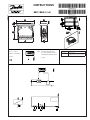
EKC 102A (115 V)
084R9974
Type: Pt 1000 (1000 Ω /0°C ) /
Ptc 1000 (1000 Ω /25°C ) /
NTC-M2020 (5000 Ω / 25°C)
( o06)
t
amb
= 0 - +55°C
115 V a.c. 50/60 Hz
1.0 VA
CE (250 V a.c.) UL (240 V a.c.)
10 (6) A
16 A relays
10 A Resistive
5FLA, 30LRA
UL-approval based on 30000 couplings
10 V < U < 256 V
Max. load must be keept.

2 Instructions RI8KJ35J © Danfoss 08/2010 EKC 102A
English
The buttons
Set menu
1. Push the upper button until a parameter
is shown
2. Push the upper or the lower button and
find that parameter you want to change
3. Push the middle button until the
parameter value is shown
4. Push the upper or the lower button and
select the new value
5. Push the middle button again to enter
the value.
Set temperature
1. Push the middle button until the
temperature value is shown
2. Push the upper or the lower button and
select the new value
3. Push the middle button to select the
setting.
Manuel start or stop of a defrost
• Push the lower button for four seconds.
Light emitting diode
= refrigeration / pull in relay
= defrost
Flashes fast at alarm
Cutout alarm / see alarm code
• Push briey the upper button
Start-up:
Regulation starts when the voltage is on.
Go through the survey of factory
settings. Make any necessary changes in the
respective parameters.
SW = 1.2X
Factory setting
If you need to return to the factory-set values, it can be done in this way:
- Cut out the supply voltage to the controller
- Keep upper and lower button depressed at the same time as you recon nect the supply voltage
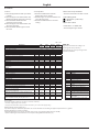
Parameters
Min.-
value
Max.-
value
Factory
setting
Actual
setting
Function Codes
Normal operation
Temperature (set point) --- -50°C 99°C 2°C
Thermostat
Differential r01 0,1 K 20 K 2 K
Max. limitation of setpoint setting r02 -49°C 99°C 99°C
Min. limitation of setpoint setting r03 -50°C 99°C -50°C
Adjustment of temperature indication r04 -20 K 20 K 0 K
Temperature unit (°C/°F) r05 °C °F °C
Correction of the signal from Sair r09 -10 K 10 K 0 K
Manual service (-1), stop regulation (0), start regulation (1) r12 -1 1 1
Compressor
Min. ON-time c01 0 min 30 min 0 min
Min. OFF-time c02 0 min 30 min 0 min
Compressor relay must cutin and out inversely
(NC-function)
c30 OFF On OFF
Defrost
Defrost method (0=none / 1=natural) d01 0 1 1
Defrost stop temperature d02 0°C 25°C 6°C
Interval between defrost starts d03 0 hours 48 hours 8 hours
Max. defrost duration d04 0 min 180 min 45 min
Displacement of time on cutin of defrost at start-up d05 0 min 240 min 0 min
Defrost sensor (0=time, 1=Sair) d10 0 1 0
Defrost at start-up d13 no yes no
Miscellaneous
Delay of output signals after start-up o01 0 s 600 s 5 s
Access code o05 0 100 0
Used sensor type (Pt /PTC/NTC) o06 Pt ntc Pt
Refrigeration or heat (rE=refrigeration, HE=heat) o07 rE HE rE
Display step = 0.5 (normal 0.1 at Pt sensor) o15 no yes no
Save the controllers present settings to the programming
key. Select your own number.
o65 0 25 0
Load a set of settings from the programming key (previ-
ously saved via o65 function)
o66 0 25 0
Replace the controllers factory settings with the present
settings
o67 OFF On OFF
Service
Status on relay
Can be controlled manually, but only when r12=-1
u58
Fault code display
A45 Standby mode
Alarm code display
E1 Fault in controller
E29 Sair sensor error
Status code display
S0 Regulating
S2 ON-time Compressor
S3 OFF-time Compressor
S10 Refrigeration stopped by main
switch
S11 Refrigeration stopped by thermostat
S14 Defrost sequence. Defrosting
S20 Emergency cooling
S25 Manual control of outputs
S32 Delay of output at start-up
non The defrost temperature cannot be
displayed. There is no sensor
-d- Defrost in progress / First cooling
after defrost
PS Password required. Set password
Warning ! Direct start of compressors *
To prevent compressor breakdown parameter c01 and c02 should be set according to suppliers requirements or in general :
Hermetic Compressors c02 min. 5 minutes
Semihermetic Compressors c02 min. 8 minutes and c01 min. 2 to 5 minutes ( Motor from 5 to 15 KW )
* ) Direct activating of solenoid valves does not require settings different from factory (0)

EKC 102A Instructions RI8KJ35J © Danfoss 08/2010 3
Español
Los botones
Ajustar parámetros
1. Pulsar el botón superior hasta que
aparece el parámetro r01.
2. Pulsar los botones alto y bajo hasta
encontrar el parámetro desesado.
3. Pulsar el botón central para ver el valor
actual.
4. Pulsar los botones alto y bajo para
modificar el valor.
5. Pulsar el botón central para confirmar el
nuevo valor.
Ajustar la temperatura de corte
1. Pulsar el botón central para ver el valor
actual.
2. Pulsar los botones alto y bajo para
modificar el valor.
3. Pulsar el botón central para confirmar el
nuevo valor.
Leer la temperatura de la sonda de deses-
carche
• Pulsar y soltar el botón bajo
Iniciar/parar un desesc. manualmente
• Pulsar y mantener el botón bajo duran-
te 4s.
LED’s en el display
= refrigeración
= desescarche
Parpadean cuando hay una alarma
Ver el código de alarma
• Pulsar y soltar el botón alto
Puesta en marcha:
El equipo empieza a funcionar cuando se
aplica alimentación eléctrica.
Revise el menú de parámetros ajustados de
fábrica. Realice los ajustes necesarios en los
parámetros correspondientes.
SW = 1.2X
The Product contains electrical components
And may not be disposed together with domestic waste.
Equipment must be separate collected with Electrical and Elec-
tronic waste. According to Local and currently valid legislation.
FC-SPMC
Ajustes de fábrica
Si se necesita volver a la programación de fábrica, se procederá del siguiente modo:
- Se corta la almientación eléctrica al EKC
- Se restablece la alimentación eléctrica mientras se mantienen pulsados los dos botones alto y bajo durante unos
segundos.
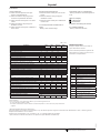
Parámetros
Valor -
mín.
Valor -
máx.
Ajuste de
fábrica
Ajuste
actual
Función Código
Funcionamiento normal
Temperatura de corte (set point) --- -50°C 99°C 2°C
Termostato
Diferencial del termostato r01 0,1 K 20 K 2 K
Límite máximo al ajustar la temperatura de corte r02 -49°C 99°C 99°C
Límite mínimo al ajustar la temperatura de corte r03 -50°C 99°C -50°C
Corrección de la temperatura del display r04 -20 K 20 K 0 K
Unidades de temperatura (°C/°F) r05 °C °F °C
Calibración de la sonda Saire r09 -10 K 10 K 0 K
Marcha/paro interno:
-1=modo manual, 0=EKC parado, 1=en marcha
r12 -1 1 1
Compresor
Mínimo tiempo de compresor en marcha (minutos) c01 0 min 30 min 0 min
Mínimo tiempo entre dos arranques consecutivos (min.) c02 0 min 30 min 0 min
Invertir el funcionaimento de la salida DO1 (compresor) c30 OFF On OFF
Desescarche
Tipo de desescarche: 0=ninguno / 1 =natural d01 0 1 1
Temperatura de fin de desescarche d02 0°C 25°C 6°C
Intervalo de tiempo entre desescarches d03 0 horas 48 horas 8 horas
Duración máxima del desescarche d04 0 min 180 min 45 min
Desplazamiento del 1
er
desescarche tras dar tensión al
equipo
d05 0 min 240 min 0 min
Sonda de fin de desescarche (0=tiempo, 1=Saire) d10 0 1 0
Desescarche al dar tensión d13 no yes no
Varios
Retardo de activación de salidas al dar tensión al equipo o01 0 s 600 s 5 s
Código 1 de acceso a todos los parámetros
(0=código desactivado)
o05 0 100 0
Tipo de todas las sondas utilizadas (Pt /PTC/NTC) o06 Pt ntc Pt
Frío / Calor (rE=frío; HE=calor) o07 rE HE rE
Precisión del valor del display: YES = 0.5, no= 0.1 o15 no yes no
Guardar la programación de un EKC en una "copy-key" o65 0 25 0
Volcar la programación desde una "copy-key" a un EKC o66 0 25 0
Sustituir los "ajustes de fábrica" por la programación actual o67 OFF On OFF
Parámetros informativos (servicio)
Estado del relé de frío (0/OFF = desact., 1/on = activado)
Puede operarse manualmente sí "r12=-1"
u58
Códigos de alarma
A45 EKC parado ( por "r12")
Códigos de fallos
E1 Fallo del controlador
E29 Error en la sonda Saire
Códigos de estado
S0 Enfriando
S2 Compresor mín. tiempo en marcha
S3 Compresor mín. tiempo arranques
consecutivos
S10 Equipo parado (desde r12 ó desde
DI)
S11 Refrig. parada (se ha alcanzado el
corte).
S14 Desescarchando
S20 Refrigeración en emergencia
S25 Control manual, forzado, activo
S32 Retraso inicial al dar tensión al
equipo
non No se puede mostrar la temp. de
desescarche. No hay sonda.
-d- Se está realizando un desescarche
PS PS : introduzca contraseña (Código
de acceso)
¡Atención! Arranque directo de compresores*
Para evitar daños en el compresor, los parámetros c01 y c02 deberán ajustarse según las recomendaciones del fabricante o bien, o de forma general:
Compresores herméticos: c02 = 5 minutos
Compresores semi-herméticos: c02 = 8 minutos y c01 = 2 a 5 minutos (Motor de 5 a15 kW)
*) Para controlar las válvulas solenoides no se requiere un ajuste diferente al de fábrica (0)

4 Instructions RI8KJ35J © Danfoss 08/2010 EKC 102A
-
 1
1
-
 2
2
-
 3
3
-
 4
4


Danfoss EKC 102A (115 V) Guía de instalación
- Tipo
- Guía de instalación
en otros idiomas
Artículos relacionados
-
Danfoss EKC 102B, EKC 102C Guía de instalación
-
-
-
-
-
-
-
-
-