
@
iNSTALLATiON AND SERVICE MUST BE PERFORMED BY
A QUALiFiED iNSTALLER.
iMPORTANT: SAVE FOR LOCAL ELECTRICAL iNSPECTOR'S USE.
READ AND SAVE THESE iNSTRUCTiONS FOR FUTURE REFERENCE.
If the information in this manual is not followed exactly, a fire or explosion may result
causing property damage, personal injury or death.
FOR YOUR SAFETY:
-- Do not store or use gasoline or other flammable vapors and liquids in the vicinity of this or any other
appliance.
-- WHAT TO DO IF YOU SMELL GAS:
Do not try to light any appliance.
Do not touch any electrical switch; do not use any phone in your building.
Immediately call your gas supplier from a neighbor's phone. Follow the gas supplier's instructions.
If you cannot reach your gas supplier, call the fire department.
-- Installation and service must be performed by a qualified installer, service agency or the gas supplier.
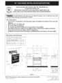
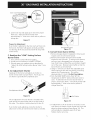
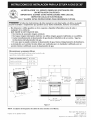
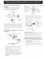
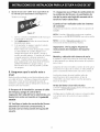
Dimensions and Clearance
Provide adequate clearance between range
and adjacent combustible surfaces.
TYPICAL CONTROL PANEL X. HEIGHT
HI Profile Control Panel 45 5/8" min.
LO Profile Control Panel 40 7/8" Min.
25 1/8"
35
X
Minimum to
wall on either
36"+ _ I/8" side of range_
above 36" heigilt
"-,..
45 318.... " ....
' Door open .................:"
\_ , _°-
36"
_36"
30" Minimum
Minimum to
18" cabinets on either
side of range
I 36 1/4"
Between Cabinets
I_ 13"-_
Maximum depth
for cabinets
above range top |
0" Min. Clearance
at rearof range
below cooktop
from the backwall.
Figure 1
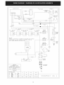
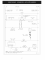
NOTE: Wiring diagrams for these appliances are enclosed in this booklet.
Printed in United States
PIN 318201758 (0605) Rev. B
English - pages 1-8
Espahol - paginas g-18
Wiring Diagrams- pages 19-20

Important Notes to the Installer
I. Read all instructions contained inthese installation
instructions before installing the range.
2. Remove all packing material before connecting the
electrical supply to the appliance.
3. Observe all governing codes and ordinances.
4. Be sure to leavethese instructions with the consumer.
Important Note to the Consumer
Keep these instructions with your Useand Care Guide for
future reference.
IMPORTANT SAFETY
INSTRUCTIONS
Installation of this range must conform with local codes,
or in the absence of local codes, with the National Fuel
Gas Code ANSI Z223. l--latest edition.
This range has been design certified by American Gas
Association (A.G.A.). As with any appliance using gas
and generating heat, there are certain safety precautions
you should follow. You will find them in the Use and
Care Guide, read it carefully.
* Be sure your range is installed and grounded
properly by a qualified installer or service
technician.
* This range must be electrically grounded in
accordance with local codes, or in their absence,
with the National Electrical Code ANSI/NFPA No.
70--latest edition.
* The installation of appliances designed for
manufactures (mobile) home installation must conform
with Manufactured Home Construction and Safety
Standard, title 24CFR, part 3280 [Formerly the Federal
Standard for Mobile Home Construction and Safety,
title 24, HUD (part 280)] or when such standard is not
applicable, the Standard for Manufactured Home
Installation 1982 (Manufactured Home Sites,
Communities and Set ups), ANSI Z225.1 latest edition,
or local codes.
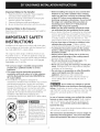
, All ranges
can tip.
* Injury to
persons
could result.
* Install anti-
tip device
packed with
range.
To reduce the dsk of tipping
of the range, the range
must be secured by properly
installed anti-tip bracket (s)
provided with the range. To
check if the bracket(s) is
installed properly, grasp the
top rear edge of the range
and carefully tilt it forward
to make sure the range is
anchored.
• Before installing the range in area covered with
linoleum or any other synthetic floor covering,
make sure the floor covering can withstand heat
at least 90°F above room temperature without
shrinking, warping or discoloring. Do not install
the range over carpeting unless you place an
insulating pad or sheet of 1/4"thick plywood
between the range and carpeting.
• Make sure the wall coverings around the range
can withstand the heat generated by the range.
• Do not obstruct the flow of combustion air at the oven
vent nor around the base or beneath the lower front
panel of the range. Avoid touching the vent openings
or nearby surfaces as they may become hot. This
range requires fresh air for proper burner combustion.
• Do not store items of interest to children in the
cabinets above the range. Children could be
seriously burned climbing on the range to reach items.
• To eliminate the need to reach over the surface
burners, cabinet storage space above the burners
should be avoided.
• Adjust surface burner flame size so it does not
extend beyond the edge of the cooking utensil.
Excessive flame is hazardous.
• Do not use the oven as a storage space. This
creates a potentially hazardous situation.
• Never use your range for warming or heating the
room. Prolonged use of the range without adequate
ventilation can be hazardous.
• Do not store or use gasoline or other flammable
vapors and liquids near this or any other
appliance. Explosions or fires could result.
• Remove broiler pan and other utensils and wipe up
excess spillage before self-cleaning the oven (if
equipped).
Do not make any attempt to operate
the electric ignition oven during an electrical power
failure. Resumption of electric power when OVENTEMP
and OVEN SETcontrols are in any position other than OFF
will result in automatic ignition of the oven or broiler
burner.
In case of a power outage, you can light the surface
burners on your range with a match. Hold a lighted
match to the burner, then slowly turn the knob to the
LITEposition. Use extreme caution when lighting
burners this way.
Surface burner in use when electrical power failure occurs
will continue to operate normally.
The oven burner and broil burner on your range are
lighted by electrical ignition. The oven and broiler
cannot be operated in the event of a power failure.

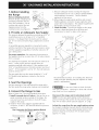
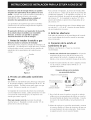
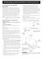
1. Before Installing Screws
the Range
Remove shipping material
Remove all tape, shipping and
packaging materials and the
oven rack packaging. Lift up
cooktop and remove the two
shipping screws from the
cooktop burners (see figure 2). Figure 2
2. Provide an Adequate Gas Supply
This range is designed to operate on natural gas at 4" of
manifold pressure or on LPgas at 10" of manifold
pressure. It is shipped from the factory set for natural
gas. If it isto be used with LPgas, adjustments must be
made.
A convertible pressure regulator is connected in series
with the manifold of the range and must remain in series
with the supply line regardless of whether natural or LP
gas is being used.
For proper operation, the maximum inlet pressure to
the regulator must be no more than 14" of water column
(W.C.) pressure.
For checking the regulator, the inlet pressure must be at
least 1" water column pressure greater than the
regulator manifold outlet setting. If the regulator is set
for 4" of manifold pressure, the inlet pressure must be at
least 5". If the regulator isset for10", the inlet pressure
must be at least 11".
The gas supply line into the range should be 1/2"or 3A"
I.D. flexible metal appliance connector five feet in
length.
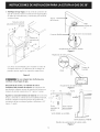
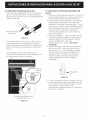
3. Seal the Openings
Seal any openings in the wall behind the range and in
the floor under the range when hookups are completed.
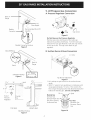
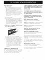
4. Connect the Range to Gas
Refer to figure 4 to 7 for recommended connections.
A. Install a manual shut-off valve in the gas line in an
easily accessible location outside of the range. Be
sure you know how and where to shut-off the gas
supply to the range.
B. Install Y2" flare union adaptor supplied with the
connector, to the Y2" NPT internal thread on pressure
regulator.
Gas Connection for Electric Ignition Models
FlareUnion Adaptor
Flexible Applia_nce Pressure
Connector Regulator
Figure 3
C. Because solid pipe restricts moving the range we
recommended use of A.G.A. design certified flexible
metal appliance connector. Connect flexible
appliance to flare union.
D. Move range into approximate position and connect
flexible appliance connector to gas supply line with
proper flare union adaptor. The adaptor supplied with
the flexible connector must be used.
E. Check for leaks. Turn the gas supply on the range
and use a liquid leak detector at all joints and
connections to check for leaks in the system.
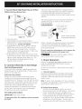
3-Wire Polarized
120_ Outlet
32 7/8" _+Y4'
20"
or Lower i
Pipe
Recommended locations for installing the electrical
outlet and pipe opening may be adjusted to meet
specific requirements.
Figure 4
Do not use a flame to check for leaks
from gas connections. Checking for leaks withaflame
may result in a fire or explosion.
Disconnect this range and its individual shutoff
valve from the gas supply piping system during any
pressure testing of that system at test pressures greater
than 14" of water column pressure (approx. F2" psig).
isolate the range from the gas supply piping system
by closing its individual manual shutoff valve during any
pressure testing of the gas supply piping system at test
pressures equal to or lessthan 14" of water column
(approx. 1/2"psig).

Backof
Range
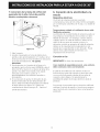
5. LP/Propane Gas Conversion
A. Pressure Regulator Conversion
1/2"
Close Nipple
NAT.
Flexible
Connector
Recommended Shut-Off
_cation
Flexible Connector Hookup
Figure 5
L.P. 1]]_ Cap Screw
Figure 8
Do Not Remove the Pressure Regulator
Remove cap-screw and snap out the nylon gas
indicator by pushing it sideways. Turn the nylon gas
indicator for type gas (Natural or LP)and snap it back
in the cap-screw. Put cap-screw back on gas
regulator.
B. Surface Burner Valves Conversion
Air Shutter
Union
Back of
Range
1 7A6" sA,,
..........
End of
Pressure
Regulator
2 5/8 "
_WaU
iii_ ii _!_?_iii_ii_i_!ii_i_!i_!i!i_i;i_i
Counter
Top
it i_
Floor
TOPVIEW FRONTVIEW
Solid Pipe Hookup
Figure 7
Nat.
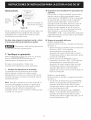
Top Burner Adjustment
Figure 9
I. Lift cooktop to gain access to the surface burner
spuds.
2. With 1/2"wrench, turn spud down or clockwise until
snug (approximately 2 1/2turns). This restricts the
flow of gas through spud to that allowed only by the
hollow LP metering pin. Do not overtighten.
Pin
Natural Gas
Increase Gas
Increase Flame Size_,,
(Pre-Set at Factory
for Natural Gas)
!
A
_--LoP.Gas
Decrease Gas
Decrease Flame
Size
Figure 10

InnerCone Flame Length
3. Lower main top and apply gas to check for proper
flame size, Flame should be steady with
approximately 1/2" blue inner cones and no yellow or
orange tips.
Figure 11
Proper Air Adjustment
If air shutter is adjusted so that too much air flows into
the burner, the flame will appear unsteady, possibly
not burning all the way around and will be noisy (like
a blow torch).
C. Readjust the "LOW" Setting Surface
Burner Valve
1. Turn control to LITEuntil burner ignites.
2. Quickly turn knob down to LOWEST SETTING.
3. If burner goes out, readjust valve as described in
"Adjust the LOW Setting Surface Burner Valve" from
Page 7.
D. Air Adjustment Shutter
Apply gas to the burner and adjust air shutter on
burner venturi tube to proper flame. ForLPgas, the
air shutter is generally left completely open.
Air adjustment shutter_
Figure 12
The air adjustment for each burner is located at the
open end of the venturi tube and sits on the hood of
the valve. The shutter is held in place by friction fit.
If air shutter needs adjusting, rotate the shutter to
allow more or less air into the burner tubes as needed.
Oven Burner Spud
Figure 13
E. Convert Oven Burner Orifice
I. Remove storage drawer if equipped or lower panel
to gain access to oven burner spuds.
2. Remove oven bottom and oven burner baffle
located on top of burner. To remove oven bottom,
pull up at rear, disengaged front of bottom from
oven front frame, and pull the oven bottom straight
out of the oven. Remove burner baffle so that the
burner flame can be observed.
3. Using 1/2"wrench, turn down the adjustable spud
which injects gas into the oven burner, until snug
against the LP metering pin. This will be
approximately 2 1/2turns. Do Not Overtighten.
4 Push the BAKETEMP button, then SETthe
temperature to 300% Wait until burner starts to
cycle To determine if the oven burner flame is
proper, observe the flame It should be steady with
approximately 1" blue cones and no yellow or
orange flame tips.
f _ Air Shutter
Figure 14
5. If adjustment to the air shutter is necessary, locate
oven burner air shutter, loosen shutter set screw and
adjust to obtain optimum flame (figure 14). This
will normally be completely open for LP gas.
Tighten shutter set screw.

F. Convert Waist High BroiJer Burner Orifice
Flame (SeJf-Clean Models Only)
The power cord of this appliance is equipped with a 3-
prong (grounding) plug which mates with a standard 3-
prong grounding wall receptacle (see Figure 8) to
minimize the possibility of electric shock hazard from the
appliance.
Figure 15
1. Open oven door.
2. Locate broiler burner spud and turn down
approximately 2 Y2turns so that spud is snug against
LPmetering pin. Do NotOvertighten.
3. To determine if burner flame is proper, push the
BROILbutton, then turn the SETknob to the LO
setting, and observe broiler flame. It should be
steady and sharp with approximately I " blue cones
and no yellow or orange flame tips.
4. If adjustment to the air shutter is necessary, locate
oven burner air shutter, loosen shutter set screw and
adjust to obtain optimum flame (figure 14). This
will normally be completely open for LP gas.
Tighten shutter set screw.
6. Connect Electricity to Gas Range
EJectrical Requirements
120 volt, 60 Hertz, individual, properly grounded and
polarized branch circuit protected by a 15 amp. circuit
breaker or time delay fuse.
Extension Cord Cautions:
Because of potential safety hazards under certain
conditions we strongly recommend against the use of
any extension cord. However, if you still select to use an
extension cord, it is absolutely necessary that it be a UL
listed 3-Wire grounding type appliance extension cord
and that the current carrying rating of the cord in
amperes be equivalent to or greater than the branch
circuit rating. Such extension cords are obtainable
through your local service organization.
Grounding Instructions
IMPORTANT Please read carefully.
For personal safety, this appliance must be properly
grounded.
The wall receptacle and circuit should be checked by a
qualified electrician to make sure the receptacle is
properly grounded.
Preferred Method
Grounding
type wall
receptacle
f
Do not, under any
circumstances, cut,
remove, or bypass
the grounding
prong.
Power supply cord with
3-prong grounding plug
Figure 16
Where a standard 2-prong wall receptacle is installed, it
is the personal responsibility and obligation of the
consumer to have it replaced by a properly grounded 3-
prong wall receptacle.
Do not, under any circumstances, cut or remove the
third (ground) prong from the power cord.
Disconnect electrical supply cord from
wall receptacle before servicing range.
7. Check Operation
Refer to the Use and Care Guide packaged with the
range for operating instructions and for care and
cleaning of your range.
Do not touch the burners. They may be hot enough to
cause burns.
1. Check the igniters
Operation of electric igniters should be checked after
range and supply line connectors have been carefully
checked for leaks and range has been connected to
electric power.
Note: If range isto be operated on LP. gas, conversion
of regulator and adjustment of burner spuds is necessary
before ignition check; refer to ???.
A) Surface Burner Igniters
To check for proper lighting, push in and turn a
surface burner knob to the LITEposition. The surface
burner should light when gas is available to top
burner. Each burner should light within 4 seconds in
normal operation after air has been purged from
supply lines. Once the burner lights, knob should be
rotated out of the LITEposition. Try each valve
separately until all burners have been checked out.

B)OvenIgniterSystem
Self-Clean Models:
Remove all materials and literature from oven and:
1. Push the BAKE TEMP button and set the oven
temperature to 300°F. Within 60 seconds the
bake (lower) burner will ignite. Check for proper
flame; push the CANCEL button.
2. Push the broil button and set the oven temperature
to 300°F. Within 60 seconds the broil (upper)
burner will ignite. Check for proper flame. Allow
burners to cycle at least one time; push the
CANCEL button.
Non Self-Clean Models:
Remove all materials and literature from oven and:
1. Turn oven temperature knob to BAKE (300°F).
Within 60 seconds the lower burner should ignite.
Check for proper flame. Turn knob to off.
2. Turn oven temperature knob to BROIL. Within 60
seconds the lower burner should ignite. Check for
proper flame. Turn knob to off.
2. Adjust the "LO" or "SIMMER" Setting of Surface
Burner Valves (see Figure 17)
Screwin Stem
9. When installation is complete, connect the
power cord and set the time of day on the
electronic oven control as explained in the
Owner's Guide.
10. Verify the operation of the electronic
control functions as per instructions given in
the Owner's Guide.
11. Make sure the air flow from the oven
vent and the air flow to the bottom front of
range is unobstructed.
When All Hookups are Complete
Make sure all controls are left in the OFFposition.
NOTE: Refer to Owner's Guide for complete instructions for
ordering parts or making inquiries about this range.
NOTE: Refer to Owner's Guide for operating instructions
and cleaning instructions.
Important: See next page for Anti-tip
Bracket Installation Instructions,
igure 17
A.
B.
C.
Turn control to LITEuntil burner ignites.
Quickly turn knob down to LOWEST POSITION.
If burner goes out, readjust valve asfollows:
Remove the surface burner control knob, insert a
thin-bladed screw driver into the hollow valve
stem and engage the slotted screw inside.
Flame size can be increased or decreased with
the turn of the screw. Adjust flame until you
can quickly turn knob from LITEto LOWEST
POSITIONwithout extinguishing the flame.
Flame should be as small as possible without
going out.
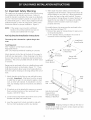
8. Make Sure Range Is Level
Level the range by placing a level horizontally on an oven
rack. Check diagonally from front to back, then level the
range by either adjusting the leveling legs or by placing
shims under the corners of the range as needed.
Model and Serial Number Location
The model and serial plate is located in the left hand
side, underneath the surface cooktop.
When ordering parts for or making inquires about your
range, always be sure to include the model and serial
numbers and a lot number or letter from the serial plate
of your range.
Your serial plate also tells you the rating of the burners
and type of fuel and the pressure the range was adjusted
for when it left the factory.
Before You Call for Service
Read the Avoid Service Checklist and operating
instructions in your Use and Care Guide.
Check to make sure the house fuse or circuit breaker for
your cooktop are not blown or open.

12. Important Safety Warning
This range must be properly secured to the floor by using
the included anti-tip brackets and screws. Failure to
install the brackets could allow the range to accidentally
tip over if excessive weight is placed on an open door or
if a child climbs upon it. Serious injury might result from
spilled hot liquids or from the range itself. Refer to the
instructions below for proper installation. Figure A.
NOTE: If the range is ever moved to a different
location, the anti-tip brackets must also be
moved and installed with the range.
Anti-tip Bracket Installation Instructions
The anti-tip kit is located in a plastic bag in the
oven.
Tools Required:
5/16" Nutdriver or Flat Head Screwdriver
Adjustable Wrench
3/16" Dia. Masonry Drill Bit (if installing in concrete)
Attach brackets to the floor at the back of the range to
hold both rear leg levelers. When fastening to the floor,
be sure that screws do not penetrate electrical wiring or
plumbing. The screws provided will work in either wood
or concrete.
Range may be anchored to floor in a dwelling house with
hold down brackets as illustrated in Figure "A". These
hold down brackets allow range to be freely pulled out
from the wall for cleaning or servicing without the use of
tools.
.
Slide range into place making sure rear legs are
trapped by ends of brackets. Range may need to be
shifted slightly to one side as it is being pushed back
to allow rear legs to align with brackets. Remove
lower panel or storage drawer to inspect brackets or
grasp the top rear edge of the range and carefully
attempt to tilt it forward to make sure range is
properly anchored.
For mobile homes, the range must be anchored to the
floor as illustrated in Figure "B".
I. Remove false panel or storage drawer to gain access
to the anchoring holes.
2. A I/4" diameter hole is provided in the center of
each base rail for anchoring to floor.
i
,-_1 i _ Install Hold
3/8" .i!Down Bracket
3/8" ..-_..... Back Edge of Range ....--.....
,_j ,-- or RearWall
! Screws
Per Bracket Range Side
Panel Location
Install Hold '"--,,,
Down Bracket "-....... _
Figure A
I. Attach brackets to the floor or rear wall with screws
provided. Important: Attachment must be secured
to solid floor or wall. Do not attach to plaster, sheet
rock, or other soft material. If attachment is to rear
wall, any moldings must be removed in area behind
range.
Base
Rail --
Body
Side
.
If brackets are to be attached to masonry or ceramic
floors, position brackets on floor and mark hole
location. Drill 3/16" holes.
Lower both rear leg levelers about three turns so the
brackets will slide over leveler head.
Level the range front to back and side to side with
the two front leg levelers and the rear levelers.
Hole ForAnchoring
Range to Floor
Hole Located Approx.
Midway of BaseRail
Figure B
Frame
Stepping, leaning or sitting on the door or
drawer of this range can result in serious injuries and also
cause damage to the range.

@
LA INSTALACION Y EL SERVIClO DEBEN SER EFECTUADOS POR
UN INSTALADOR CAUFICADO.
IMPORTANTE: GUARDE ESTAS INSTRUCClONES PARA USO DEL
INSPECTOR LOCAL DE ELECTRIClDAD.
LEA Y GUARDE ESTAS INSTRUCClONES PARA REFERENCIA FUTURA.
ir_ Si todas las instrucciones de _ste manual no son observadas a la letra, se puede
ocurrir incendios o explosiones que pueden causar daEos materiales, lesiones o la muerte.
- No almacene o utilice gasolina u otros vapores y liquidos inflamables cerca de este o
cualquier otro artefacto.
- QUE HACER SI HAY FUGAS DE GAS
* No intente de encender ningun artefacto
* No toque ningun interruptor el_ctrico; no utilice ningun aparato telef6nico en su edificio.
* Llame inmediatamente el abastecedor de gas desde el telef6nico de un vecino. Siga las
instrucdones del abastecedor de gas.
* En caso que no puede contactar el abastecedor de gas, Ilame al departamento de bomberos.
- La instalaci6n y el servicio t@cnico deben set realizados por un instalador calificado, por un
servicio t@cnico certificado o por el abastecedor de gas.
Dimensiones y espados libres
Provee adecuados espacios libres entre la estufa y las
superficies combustibles adyacentes
PANEL DE CONTROL TIPICO ' X. ALTURA
Panel de control bajo
Panel de control alto
35
45 5/8" Min.
40 7/8" Min.
25 1/8"
X
36 _+1/8"
Min. hasta la pared
a cualquier lado de
la estufa superior a_
36" de altura.
36"_
30" Minimo
l Minimo hasta
los gabinetes a
18" cualquier lado
_*_ 1 de la estufa.
36 I/4"
entre los gabmetes
Figura 1
_13"_
Profundidadm_ixima
paraIosgabinetesque•
seencuentranpor|
arribadelaestufas_
Separation minima
de 0" en la parte
posterior de la estufa
debajo de la cubierta
de la pared trasera
NOTA: Se adjunta los diagramas de cables de estas estufas con el libreta.
Impreso en los Estados Unidos
P/N 318201758 (0605) Rev. B
English - pages 1-8
Espariol - paginas 9-18
Diagrama de la instalaci6n dambrica - pages 19-20

Notas importantes para el instalador
I. Lea todas las instrucciones contenidas en este manual
antes de instalar la estufa.
2. Saque todo el material usado en el embalaje del
compartimiento del homo antes de conectar el
suministro elOctrico a la estufa.
3. Observe todos los cOdigosy reglamentos pertinentes.
4. Deje estasinstrucciones con el comprador.
Nota Importante para el Consumidor
Conserve estas instrucciones y el Manual del Usuario para
referencia futura.
IMPORTANTES
INSTRUCCIONES DE
SEGURIDAD
La instalaciOn de esta estufa debe realizarse en
conformidad con los cOdigos locales o, si 6stos no
existen, con el National Fuel Gas Code ANSI Z223.1 -
Oltima ediciOn.
El diseno de esta estufa cuenta con la aprobaciOn de la
American Gas Association. AI igual que todos los
artefactos a gas que generan calor, deben seguirse
ciertasmedidasdeseguridad. Vienen con eI Manual de
utilizaciOnymantenimiento. Lea el manual
atentamente.
• Aseg_rese que la estufa sea instalada
correctamente pot un instalador o t_cnico
calificado.
• La estufa debe conectarse el_ctricamente a tierra
de acuerdo con los c6digos locales o, de no
existir, con el c6digo el_ctrico ANSI/NFPA No. 70 -
_ltima edici6m
• La instalaciOn de unidades disenadas para casas
(movibles) deben cumplir con los estandares de
"Manufactured Home Construction and Safety
Standard, title 24 CFRpart 3280". (Anteriormente
Todas las estufas
pueden volcarse.
i• Esto podria
resultar en
lesiones
personales.
Instale el
dispositivos
antivuelco que se
ha empacado
junto con esta
estufa.
Reducir el
riesgo de que se vuelque la
estufa, hay que asegurarla
adecuadamente colocandole
los soportes antivuelco que se
proporcionan. Para
comprobar siestos estan
instalados y apretados en su
lugar como se debe, ase el
borde trasero superior de la
estufa y cuidadosamente
inclinela hacia adelante para
asegurar que la estufa se
ancle.
"The Federal Standard for Mobile Home Construction
and Safety title 24, HUD (Part 280)". Ocuandoestos
estandaresnoseanaplicables: "The Standard for
Manufactured Home Installation 1982, (Manufactured
Home Sites, Communities and set-ups), ANSI Z225.1,
Oltima ediciOn o cOdigos y regulaciones locales.
• Antes de instalar la estufa en una _rea recubierta
con lin61eo o cualquiera otra cubierta de suelo
sint_tico, aseg_rese que la cubierta puede resistir
a una temperatura de al menos 90° Fde calor
superior a la temperatura de la pieza, sin
contraerse, deformarse o descolorirse. No
coloque la estufa sobre una carpinteria a menos
que instale un soporte aislante o una plancha
contrachapada de 1/4"de espesor entre la estufa y
la carpinteria.
• Aseg_rese que el tapiz de la pared alrededor de la
estufa puede resistir al calor generado pot la
estufa.
No obstruya la circulaciOn de aire de combustiOn en las
ventilaciones del homo, ni alrededor de la base, ni
debajodeltablerofrontaldelaestufa. Evitetocarlas
aberturas de ventilaciOn y las superficies cercanas pues
6staspuedencalentarse. Estaestufarequiereaire
fresco para que el quemador haga la combustion
adecuadamente.
• No almacene articulos que interesan los ni_os en
los armarios que est_n pot encima de la estufa.
Les podria causar quemaduras gravas si intentan
subirse para alcanzarlos.
• Para eliminar toda posibilidad de alargar el brazo
por encima de los superficies de los quemadores,
es necesario eliminar todos los armarios pot
encima de los quemadores.
• Grade el tamaffo de la llama de modo que no
sobrepase el borde del ustensilio sobre la plancha
decocinar. Unallamaexcesiva puedeser peligrosa.
• No use el homo como espacio de
almacenamiento. EsasituaciOn puede ser peligrosa.
• No utilice jam_s su estufa como calefactor. El uso
prolongado de la estufa sin la ventilation adecuada
puede ser peligroso,
• No guarde o haga uso de gasolina o otros vaporos
y liquidos inflamables acerca de est& o cualquier
aparato. Sepuederesultaren incendioso
explosiOnes.
• Remueva la bandeja de la parrilla y otros utensilios, y
todo derramamiento antes de usar el ciclo de limpieza
a si misma.
10
No trate de usar el homo de
encendido el_ctrico durante un corte de energla. El
reestablecirniento del servicio elOctrico cuando los
controles de TEMP DELHORNO y de REGULACION DEL
HORNO estan en cualquier posiciOn diferente a
APAGADO causaria el encendido automatico del
quemador del homo o del quemador de la parrilla.

Duranteuncortedeenergiael_ctricasepueden
encenderlosquemadoresdelacubiertaconuna
cerilla, Acerqueunacerillaencendidaalquemadory
luegogirelentamenteelbotOnalaposition
ENCENDIDO(LITE).Tengaextremo cuidado al
encender los quemadores en esta forma,
Los quemadores de superficie que est_n encendidos
cuando ocurra el torte de energia elOctrica seguiran
funcionando normalmente.
El quemador del horno y el quemador de la parrilla
de su estufa estan encendidos con encendido
el_ctrico, El horno y la parrilla no pueden
funcionar durante un torte de energia.
1. Antes de instalar la estufa a gas
Remueva todos los articulos de embalaje
Retire toda la cinta, todos los articulos de embalaje y de
expedici0n, y el embalaje de la rejilla del horno. Levante
la plancha para cocinar y remueva los dos tornillos de
expedici0n de los quemadores de la plancha para
cocinar.
_ ._Tornillos
Figura 2
2. Provea un adecuado suministro
de gas
Esta estufa ha sido disenada para utilizar gas natural de
4" de presi0n m01tiple, o para utilizar gas PL de 10" de
presi0n mL_ltiple. Defabricavienepara usarse con gas
natural. Paraquesepueda usarcongasPL.
Un regulador de conversion de presi0n esta conectado
con el m01tiple de la estufa, y debe permanecer en serie
con la linea de suministro de gas, no importa siesta
usando gas natural o gas PL
Para que manejo correcto, la presion de entrada
maxima haciael. Reguladornodebeexceder 14" de
presion de la columna de agua.
Para controlar el regulador, la presi0n de entrada debe
ser de al menos 1" mayor que el ajuste de la presi0n del
m01tipledelregulador. Sielreguladorseajustaa4" de
la presiOn del m01tiple, la presi0n de entrada debe de ser
dealmenos5". Sielreguladorseajustaa 10" dela
presi0n del m01tiple, la presi0n de entrada debe de ser
de al menos 11".
La linea de suministro de gas por el homo debera tener
un tubo de _/2"o I.D. de 3A" conector de metal flexible
de una Iongitud de cinco pies.
3. Selle las aberturas
Selle todas las aberturas en la pared detras de la estufa
yen el suelo debajo de la estufa cuando los montajes
estan terminados.
4. Conexion de la estufa al
suministro de gas
RefiOrase alas figuras 4 a 7 para las conexi0nes
recomendadas.
A. Instale una v_lvula de cierre manual en la linea de
suministro de gas en un sitio de facil acceso en la
parteexteriordelaestufa. Aseg0rese de saber de
d0nde y como cerrar el suministro de gas de la estufa.
B. Instale el ensanchamiento de union o adaptor provisto
con el conector, al filete interno NPT de Y2" al
regulador de presi0n.
Conexion del gas en los modelos
con encendido el_ctrico
Adaptor o ensanchamiento
de union
t
Conector de
artefacto flexible
de presion
Figura 3
C. No es fadl de mover la estufa a causa de su tuber[a
solida, por eso recomendamos de utilizar un conector
de metal flexible dedisenoAGAcertificado. Conecte
el conector de metal flexible al ensanchamiento de
union.
D. Mueva la estufa en su prosici0n aproximada y conecte
el conector flexible a la linea de suministro de gas con
el ensanchamiento de union adecuado. Debeusarse
el adaptor provisto con el conector flexible.
11

E.Verifiquesihayfugas.D_lavueltaalsuministrode
gasdelaestufayutiliceundetectordefugasliquidas
entodaslasarticulacionesyconexionesparaverificar
siexistenfugas.
Tomadecorrient
polarizadode3alambres
de120V
_ 25"
327/s"_+X" Tubieriade
suministrod(
gas
20" 3A,,
omenosI
i
.-'" 36X"
Trasera
de la estufa
Conector flexible
Niple
cerrado de
1/2"
Sitio de cierre recomendado
Acoplamiento de conector flexible
Figura 5
RegulaciOn de cierre
Los sitios recomendados para instalar la toma de
corriente electrica y la abertura de la tuberia se
pueden ajustar seg0n los requisitos especificos.
Figura 4
No use ning_n tipo de llama para
verificar si hay fugas de gas.
Desconecte la codna y su v_lvula de cierre
individual del sistema de tuberia del suministro de
gas durante cualquier ensayo de presiOn del sistema en
ensayos de presiOn superiores a 14" (aprox. 1/2psig.)
Aparte la codna del sistema de tuberia del suministro
de gas, cierrando su valvula de cierre individual manual,
durante cualquier ensayo de presiOn del systema de
suministro de gas en ensayos iguales o inferiores a 14"
(aprox. 1/2psig.)
Union
Trasera de
la estufa
Niple 1/2" ]
[III IIII
63/8,,-I
Acoplamientode tuberiasolida
Figura 6
2 5/8"
17/16" 3A" _ Pared
I
ITT 1/2,, M {
t
Ldor del mostrador
preslon
VISTA DESDELA ALTURA ........... --
/ ..........Suelo
VISTA DESDEEL FRENTE
Detalles de acoplamiento de tuberia solida
Figura 7
12

5. Conversi6n de gas propano/
licuado
A. Conversion el regulador de presion
No remueva el regulador de presi6n
Figura 8
NAT
de
Remueva el tornillo de cabeza y suelte el indicator de
gas denilOnempujandoledelado. Gire el indicator de
gas de nilOn para usar con la especie de gas deseado
(NaturaloPL) y sit0eledenuevoen el tornillo de
cabeza. Vuelvaa ponereltornillodecabezasobreel
regulador de gas.
B. Conversion las valvulas para quemadores
de superficie
Obturador de aire
Pasador_
Gas natural
Aumentar el gas
Aumentar el tamano _,
de la llama
(De fabrica viene
para usarse con gas
natural)
Junta en forma de
- bellota
PL Gas
Disminuir el gas
Disminuir el
tamano de la
llama
Figura 10
3. Rabaje la superficie superior y abre el gas para
determinar si el tamano de la llama es la apropiada.
Esta debe estar estable formando conos internos
azules de Y2" aproximadamente sin extremos
amarillos o anaranjados.
TamcannOodie/IleanmoaiSde_
Figura 11
Ajuste de entrada de aire
Si el obturador de aire esta dejando pasar demasiado
aire al quemador, la llama sera inestable,
posiblemente no habra llama a todo el rededor del
quemador, y esta sera ruidosa (como un soplete).
#
Pasador
Ajuste del quemador superior
Figura 9
I. Levante la cubierta de la plancha de cocinar para
acceder alas juntas en forma de bellota de las
quemaduras de superficie.
2. Usando una Ilave de Y2", volt6e la junta en forma
de bellota hacia abajo o en el sentido de las
manecillas de un reloj hasta que est6n
completamente ajustadas (aproximadamente 2 Y2
vueltas). Esto restringe el flujo de gas a trav6s de la
junta, permitiendo solamente el flujo de gas por el
pasador de mediciOn de gas PL.No apriete
demasiado.
C. Ajuste la regulacion de "LOW" de la
superfide de las valvulas para quemadores
I. Gire los controles a ENCENDIDO (LITE) hasta que el
quemador se encende.
2. Gire r_pidamente el boton de control hasta la
posicion mas baja.
3. Si el quemador se apague, reajuste la valvula como
se muestra a continuaciOn: (como se muestra en la
pagina 18).
13

D_ Obturador de ajuste para eJ aire
Proporcione gas al quemador y ajuste el obturador de
gas en el v6nturi para obtener una llama adecuada.
Para gas LP,el obturador de aire se deja generalmente
abierto, sinembargo.
P
Obturador de ajuste
para el aire
hgura 12
El obturador de ajuste de aire, para cada uno de los
cuatro quemadores, esta Iocalizado en el extremo
abierto del v6nturi posicionado sobre la capucha de la
valvula. El obturador es mantenido en su punto por
fricciOn.
Si el obturador de aire necesita ajuste, gire el
obturador para permitir mas o menos entrada de aire
en los quemadores (segOn se necesite).
E. Convierta el orifido del quemador del
homo
I. Remueva el caj6n de almacenamiento si el horno le
tiene o el panel inferior para acceder alas juntas en
forma de bellota de las quemaduras del horno.
2. Remueva la parte inferior del homo y el resonador
del quemador situado sobre la extremidad del
quemador. Pararetirarelfondodelhorno. Tirela
partedeatras, sueltela partefrontaldelfondodel
homo del armaz6n del homo, y tire el fondo del
homoenlinearectadelhorno. Remuevael
resonador del quamador para poder observar la
llama del quemador.
3. Usando una Ilave de Y2", giro hacia abajo la junta
en forma de bellota ajustable que inyecta gas al
quemador del homo, hasta que ajuste contra el
pasadormedidordeP.L Estosera
aproximadamente2Y2vueltas. Noapriete
damasiado_
4. Aprete el boton de ASAR y ajuste la temperatura
del homoa300%. Esperehastaqueelhomo
alterne entre "on" y "off" (prendido y apagado).
Para determinar si el tamano de la llama es la
apropiada, observelallama. Estadebeestar
estable formando conos internos azules de 1"
aproximadamente sin extremos amarillos o
anaranjados.
Junta en
forma de
Obturador de
aire
Figura 14
5. Si sea necesario de ajustar el obturador de aire,
Iocalice el obturador de aire del quemador del
homo, afloje el tornillo del obturador y ajuste
para obtener la llama optima. Sera
completamente abierta para gas PL. Apriete el
tornillo del obturator.
Junta en forma de bellota del
quemador del homo
Figura 13
14

F. ConversiOn de la llama del orificio del
quemador de la alta cintura de parrilla
(Modelos autolimpiables solamente)
6. Conexi6n de la electricidad a la
estufa
Requisitos el_ctricos
Un circuito de caflerias particular conectado
correctamente a tierra de 120 voltios, 60 Herz protegidos
por un interruptor autometico de 15 amp. o un fusible de
retardo.
Junta en
forma de
Figura 15
I. Abre la puerta.
2. Localice el quemador en forma de bellota de la
parrilla, y gire aproximadamente 2 Y2vueltas, de tal
modo que la junta en forma de bellota se asea junta
alpasadordemediciOn PL Noapriete
demasiado,
3. Para determinar si el tamano de la llama es la
apropiada, aprete el boton para HORNEAR y gire el
boton de SETal marco LO, y observe la llama de la
parrilla. Estadebeestarestableybien aguda
formando conos internos azules de 1"
aproximadamente sin extremos amarillos o
anaranjados.
4. Si sea necesario de ajustar el obturador de aire,
Iocalice el obturador de aire del quemador del
homo, afloje el tornillo del obturador para obtener
lallamaoptima(veafigura 14). Deberaser
completamenteabierta paragasPL Aprieteel
tornillo del obturator.
Tenga extremo cuidado a la utilizad6n de un cable
flexible de extensi6n:
La utilizaciOn de un cable flexible de extension puede ser
muy peligrosa; recomendamos de no utilizar un cable
flexible de extension. Sin embargo, sideseeutilizara
cualquier precio un cable de extension, debera ser un
cable UL de tres patas de conexiOn a tierra y la
derivaciOn corriente en amperios del cable de extension
debera ser de capacidad normal equivalente o mas
grandequelacapacidaddelcircuitoderivado. Puede
obtener estos cables flexibles de extension a su
organizaciOn de servicio local.
Conexion a tier
IMPORTANTE Por favor, lea atentamente.
Como medida de seguridad personal, este artefacto
debe conectarse a tierra correctamente.
El cable de encendido de este artefacto incluye un
enchufe de tres patas (de conexiOn a tierra) que calza
con un enchufe de pared estandar de tres patas de
conexiOn atierra (Figura. 16) para disminuir la
posibilidad de peligro de choques elOctricos desde el
artefacto.
Se aconseja al consumidor que un electricista calificado
verifique el enchufe de pared y el circuito para asegurar
que el enchufe est6 conectado a tierra correctamente y
polarizado.
15

Metodo preferido f No debe, bajo A)
ninguna
Enchure
de pared a
tierra
del cable de
encendido
Cablo de encendido con
enchufe de tres patas a
tierra
Figura 16
DOnde se encuentre un toma standard de dos patas, sera
responsabilidad personal y obligaciOn del comprador
reemplazarlo por un enchufe de pared de tres patas
correctamente conectado a tierra.
Dispositivos de encendido de Jos quemadores de
superfide
Para verificar el correcto encendido, presione hacia
adentro y gire una valvula de quemador superior
hastala posiciOn "ENCENDIDO"(LITE). EIquemador
de superficie debe encender cuando el quemador
superiortienegasdisponible. Cadaunodelos
quemadores debe encenderse dentro de cuatro (4)
segundos en el modo de funcionamento normal
despuOs de haber purgado el aire de la linea de
suministro de gas. Unavezelquemadorencienda
debe cambiarse a una posiciOn diferente a
"ENCENDIDO" (LITE). Cadavalvula debechequearse
independientemente hasta que todos los quemadores
hallan sido revisados.
No debe, bajo ninguna circunstancia cortar o retirar
Ja tercera pata (tierra) del cable de encendido.
Desconecte el cable elOctrico del toma de
la pared antes de hacer mantenimiento.
7. Verifique la operacion
Refiera el Manual del usuario que viene con la eatufa
para las instrucciones de funcionamiento y el
mantenimiento y la limpieza de su estufa.
No toquealosquemadores. Puedenestar
suficientemente calientes par causar quemaduras.
1. Verifique los dispositivos de encendido
La manipulaciOn de los dispositivos de encendido
elOctrico deberan verificarse tras haber revisado
detenidamentela estufaylosconectoresdeltubodel
suministro de fugas y tras haber conectado la estufa al
suministro elOctrico.
Nota: Paraquesepueda usarlacocinacongasPL, la
conversion del regulador de presiOn y el ajuste de las
juntas en forma de bellota de los quemadores deben
realizarse antes de verificar los dispositivos de
encendido; refiere a "Como convertir la estufa para que
se pueda usar con gas PL"
B)
Sistema de encendido del horno
Modelos autolimpiables:
Remueva todos los articulos y el paquete de literatura
del homo, y:
1. Aprete el boton para ASAR y ajuste la temperatura
delhomoa300F. En60segundos
aproximadamente, el quemador de asar
(quemador de la parte inferior) debe encender.
Verifique para obtener la llama adecuada y aprete
el boton de CANCELAR.
2. Aprete el boton para HORNEAR y ajuste la
temperatura delhomoa300F. En60segundos
aproximadamente, el quemador de hornear
(quemador de la parte superior) debe encender.
Verifique para obtener la llama adecuada. El
quemador debe alternar entre encendido y
apagado pot Io menos una vez antes de apretar el
boton de CANCELAR.
Modelos no autolimpiables:
Remueva todos los articulos y el paquete de literatura
del homo, y:
I. Gire el boton de temperatura para ASAR (BAKE)
(300°F). En60segundosaproximadamente, el
quemador de la parte inferior debe encender.
Verifiqueparaobtenerlallamaadecuada. Gireel
boton de temperatura a OFF.
2. Gire el boton de temperatura para HORNEAR
(BROIL). En60segundosaproximadamente, el
quemador de la parte inferior debe encender.
Verifiqueparaobtenerlallamaadecuada. Gireel
boton de temperatura a OFF.
16

2_
Ajuste e] marco de "LOW" de ]a supercificie de
las valvuias para quemadores (vea figura 17)
Tornillo en el vastago
11. Asegurese que el flujo de combusti6n de
la ventiiacion del homo y la ventilaci6n de
aire de la parte m&s baja del armazon de la
estufa no est_n obstruidos.
Figura 17
.
2.
3.
Gire los controles a ENCENDIDO (LITE)hasta que
el quemador se encende.
Gire r_pidamente el boton de control hasta la
POSICION MAS BAJA.
Si el quemador se apague, reajuste la valvula
como se muestra a continuaci6n:
Retire el bot6n de control del quemador, inserte
un destornillador de cuchillo delgado en el
vastago del agujero de la valvula y encaje el
tornilloranuradoadentro. EItamaflodelallama
se puede aumentar o disminuir girando el
tornillo. GradOelallamahastaquesepueda
girar rapidamente hacia abajo desde LITEhasta
LOWEST POSITION sin apagar la llama. La
llama debera ser Io mas baja posible y estable
sin apagarse.
8. Asegurese que la estufa esta a
nivel
Nivele la estufa, instalado un nivel horizontalmente sobre
una rejilla del horno. Verifique en diagonal de adelante
hacia atras, y nivele la estufa ajustando las patas de
nivelaci6n o poniendo cutlas por debajo de los ric6nes de
la estufa como sea necesario.
9. Despues de la instalad6n, conecte el cable
de energia y ponga el control de la
regulation del reloj del homo electrOnico a la
buena hora como se muestra en la guia del
usuario.
Cuando se han realizado todos los sistemas
de conexi6n
Asegurese que todos los controles estan en la posiciOn de
apagado.
NOTA: Consulte el Manual de usuario para completas
instrucciones o soliciud de informaci6n acerca de su estufa.
NOTA: Consulte el Manual de usuario para las
instrucciones de funcionamiento y limpieza.
Importante: Vet la pagina 10 para las
instrucciones de instalaci6n del soporte
antivueko,
Modelo y ubicacion del nemero de serie
El modelo y la placa de nurnero de serie estan ubicados
al lado izquierdo, por debajo del armazOn de la )lancha
para cocinar.
AsegOrese de incluir el modelo y nOmero de sene que se
encuentran en la plata de su estufa, en todo pedido de
partes o solicitud de informaci6n acerca de su estufa.
La plata de nOmero de serie tambi6n indica las
especificaciones de los quemadores, el tipo de
combustible y la presi6n para la cual fue ajustada la
estufa en la fabrica.
Antes de Ilamar al servido t_cnJco
Consulte el Manual del usuario para las instrucciones de
functionamiento u limpieza.
Verifique que los fusibles de la casa no se hayan fundido
o el cortacircuitos de la estufa no hayan saltado o
abierto.
10. Verifique si todos los controles del homo
electr6nico funcionan correctamente, in
acuerdo con las instrucdones de la guia del
usuario.
17

12. Advertencia de seguridad
importante
Esta estufa debe ser asegurada al piso usando las
platinas de anclaje y los tornillos suministrados. El no
instalar apropiadamente los soportes antivudco puede
Ilegar a permitir que la estufa se incline hacia adelante,
accidentalmente, si se coloca un peso excesivo sobre la
puertaabiertaosiun ninosesubeenella. Laestufa
caliente a los liquidos calientes derramados podrian
causarseriaslesionespersonales. Refi_rasealas
instrucciones que se dan a continuaciOn para la correcta
instalaciOn de los soportes antivuelco. Figura A.
NOTA: Simuevalaestufaaotrositio, debatambien
mover los soportes antivuelcopara instalarlas con
la estufa.
Instrucciones para de instalad6n del
soporte antivueJco
Las piezas se encuentran en un saco de plastico en
el homo.
Herramientas requeridas:
Llave de tuerca de 5/16" o destornillador de cabeza
plana
Llave ajustable
Broca para mamposteria de 3/16" de diametro (para
taladrar concreto)
Asegure las platinas al piso en la parte posterior de la
estufa de forma que soporten las dos platas niveladoras
traseras. AI colocarlas aseg0rese de no perforar
alambres el6ctricos o tuberia. Lostornillos suministrados
pueden usarse en concreto o madera.
La estufa puede anclarse al piso en una residencia con
las platinas de anclaje, tal como se ilustra en la figura
"A". Estasplatinaspermitenquelaestufasehalehacia
adelante para su limpieza o reparaciOn, sin necesidad de
usar herramientas.
I. Asegure las platinas de anclaje al piso o a la pared
posterior con los tornillos suministrados. Importante:
las platinas deben anclarse sobre madera o piso
sOlido. Nodebenanclarsesobreestuco, chapade
rocaoalg0notromaterialdebaja resistencia. Siel
anclaje va a hacerse sobre la pared posterior, deben
removerse todas la molduras que queden detras de la
estufa.
2. Si las platinas van a anclarse en pisos de manposteria
o ceramica, coloque las platinas en el piso y marque
la ubicaci6n de los orificios. Taladre orificios de
3/I 6".
3. Gire las patas niveladoras 3 vueltas hacia abajo de
forma que las platinas deslicen sobre las cabezas
niveladoras.
4. Nivele la parte delantera y trasera de la estufa y las
partes laterales con los dos niveladores de pata
delanteros y los niveladores traseros.
.
Deslice la estufa hasta que quede en su lugar
asegurandose de que las patas traseras estan
atrapadasbajolasplatinasdeanclaje. Puedeser
necesario balancear la estufa hacia los lados a
medida que se desliza hacia atras para Iograr que las
platas traseras se alin6en con las platinas de anclaje.
Para asegurarse de que la estufa esta correctamente
anclada remueva el cajOn de almacenamiento o el
panel inferior, tambi6en puede verificarse la
instalaciOn tratando, cuidadosamente, de inclinar la
estufa hacia adelante.
En casas mOviles la estufa debe anclarse al piso come se
muestra en la figura B.
I. Remueva el panel falso o el cajOn de
almacenamiento para poder alcanzar los orificios de
anclaje.
2. En el centro de cada riel de la base de la estufa se
suministra un orificio de Y4" para el anclaje al piso.
i
1, 3/8
_" _ Instalar
I i / platinas
_. de anclaje
3/8" --"" ".........
,_ ,.-"_... Borde posterior de la "_..
-'_'i _'- /--""" estufa o pared posterior /7
j i_2 Tornillos
!/_ por platina Ubicacion de los paneles
laterales de la estufa
Instalar "--,.
platinas '--.,.
de anclaje ""-,..
Figura A
Parte
lateral del
cuerpo
Riel --
de la base
Orificio para anclar la estufa al
piso orificio ubicado
aproximadamente en la mitad
del riel
Figura B
Armazon
frontal
Pararse, aOyarse o sentarse en la puerta o
cajon de estaestufa causarseriaslesionespersonalesytambi@l
puede danar laestufa.
18

CLOCK ES I00
[ _--OPTIONAL ]
I BALLAST I
I J
i i
l ..............................._ C OVEN ]
' LAMP ]
II SWITCH i
__ I -- FLUORESCENTI
i STARTER i
j_ FLUORESCENT _-b i _ 1 J
l _T LAMP i I
_ll l l_ (E_ ----__
i
R,F IGNITER L F IGNITER
SW ITCH SW ITCH SW ITCH
R R. IGNITER GRIDDLE IGNITER L R IGNITER ROWER
SW ITCH SV ITCH SW ITCH CONNECTOR
CAU T I ON :
LABEL ALL WIRES PRIOR TO DISCONNECTION _HEN SERVICING CONTROLS
M{RINGS ERROR CAN CRUSE IMPROPER AND DANGEROUS OPERATION
VERIFY PROPER OPERATION AFTER SERVICING
<(
WARNING
DISCONNECT POWER
BEFORE SERVICING UNIT
TRACER MIRE: gIBE COLOR NOTED FIRST.
STRIPE NEXT
EXAMPLE¸GREEN_ll_E _ITH YELLOW51"RIPE
COLOR CODE
8 BLACK P - P}NK
BL - BLUE PR - PURPLE
BR _ BROWN R - RED
C , _ COPPER T - TAN
G - GREEN v - V_OLET
GY GREY W - WHITE
O - ORANGE Y YELLOW
BAKE / BROIL
VALVE
BAKE
CONNECTOR
NEUTRAL
CONNECTOR
OVEN
LANP
PWR NEU
SPARK
MODULE
-_- TOP BURNER
IGNI TERS
E
_Z_]
CHASSIS
GROUND
2 18 125
1 20 125
WIRE GAGE TEHP °C
3173
3173
UL STYLE
cOoSSR
CONN.
ROWER
CORD
PLUG
318045811 nEv. A
19

L
NE NEUTRALGROUND
POWER CORD L CHASSIS
CONNECTOR GROUND
CLOCK
POWER CORD_
CONNECTOR
FLUORESCENT
FLUORESCENT _TER
LAMP SWITCH BALLAST
FLUORESCENT
..........................................................................................
xJ_ NEUTRAL
CONNECTOR
/
I GN I TER I GN 1TER _-]
HARNESS SWITCHES
CONNECTOR
TOP BURNER
IGNIIERB
TIMER ES 100
OVEN LAMP
SW ITCH _S]_
%U
OVEN LAMP
PROBE
SPARK
MODULE
CAUTrON:
LABEL ALL _IRES PRIOR TO DISCONNECTION WHEN SERVICING CONTROLS
WIRINGB ERROR CAN CAUSE IMPROPER AND DANGEROUS OPERATION
VERIFY PROPER OPERATION AFTER SERVICING
BAKE
CONNECTOR
OVEN
IGNITER
OVEN
VALVE
REVA
20
-
 1
1
-
 2
2
-
 3
3
-
 4
4
-
 5
5
-
 6
6
-
 7
7
-
 8
8
-
 9
9
-
 10
10
-
 11
11
-
 12
12
-
 13
13
-
 14
14
-
 15
15
-
 16
16
-
 17
17
-
 18
18
-
 19
19
-
 20
20


Tappan TGF605EU1 Guía de instalación
- Categoría
- Cocinas
- Tipo
- Guía de instalación
en otros idiomas
- English: Tappan TGF605EU1 Installation guide
Artículos relacionados
Otros documentos
-
Estate MGR5605W Manual de usuario
-
Whirlpool AGR4433XDW0 Guía de instalación
-
Amana TGG222VDB Manual de usuario
-
-
Maytag MGR5605WB Installation Instructions Manual
-
-
Kenmore 79030552802 Guía de instalación
-
Maytag LPR1115ADW Guía de instalación
-
Frigidaire FFGC2605LWA Guía de instalación
-