Important Notes to the Installer
1. Read all instructions contained in these installation
instructions before installing the range.
2. Remove all packing material before connecting the
electrical supply to the appliance.
3. Observe all governing codes and ordinances.
4. Be sure to leavethese instructions with the consumer.
Important Note to the Consumer
Keep these instructions with your Useand Care Guide for
future reference.
IMPORTANT SAFETY
NS
Installation of this range must conform with local codes,
or in the absence of local codes, with the National Fuel
Gas Code ANSI Z223. l--latest edition.
This range has been design certified by American Gas
Association (A.G.A.). As with any appliance using gas
and generating heat, there are certain safety precautions
you should follow. You will find them in the Use and
Care Guide,, read it carefully.
• Be sure your range is installed and grounded
properly by a qualified installer or service
technician.
This range must be electrically grounded in
accordance with local codes, or in their absence,
with the National Electrical Code ANSI/NFPA No.
70--latest edition.
Tile installation of appliances designed for
manufactures (mobile) home installation must conform
with Manufactured Home Construction and Safety
Standard, title 24CFR, part 3280 [Formerly tile Federal
Standard for Mobile Home Construction and Safety,
title 24, HUD (part 280)] or when such standard is not
applicable, the Standard for Manufactured Home
Installation 1982 (Manufactured Home Sites,
Communities and Set ups), ANS! Z225.1 latest edition,
or local codes.
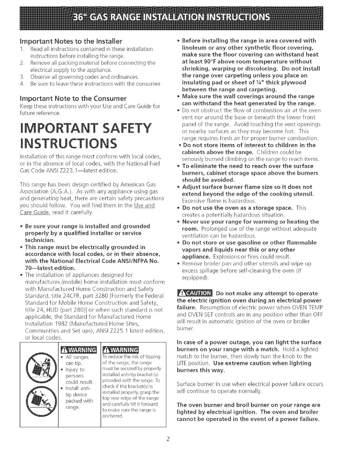
, All ranges
can tip
• Injury to
persons
could result.
• Install anti-
tip device
packed with
range,
]b reduce the risk of tipping
of the range, the range
must be secured by properly
installed anti-tip bracket (s)
provided with tile range. ]b
check if the bracket(s) is
installed properly, grasp tile
top rear edge ol the range
and carefully tilt it forward
to make sure tile range is
anchored
• Before installing the range in area covered with
linoleum or any other synthetic floor covering,
make sure the floor covering can withstand heat
at least 90°F above room temperature without
shrinking, warping or discoloring. Do not instatt
the range over carpeting unless you place an
insulating pad or sheet of 1/4"thick ptywood
between the range and carpeting.
• Make sure the wall coverings around the range
can withstand the heat generated by the range.
• Do not obstruct tile flow of combustion air at the oven
vent nor around the base or beneath the lower front
panel of the range. Avoid touching the vent openings
or nearby surfaces as they may become hot. This
range requires fresh air for proper burner combustion.
• Do not store items of interest to children in the
cabinets above the range, Children could be
seriously burned climbing on the range to reach items.
• To eJiminate the need to reach over the surface
burners, cabinet storage space above the burners
should be avoided.
Adjust surface burner flame size so it does not
extend beyond the edge of the cooking utensil,
Excessive flame is hazardous.
• Do not use the oven as a storage space. This
creates a potentially hazardous situation.
• Never use your range for warming or heating the
room. Prolonged use of tile range without adequate
ventilation can be hazardous.
• Do not store or use gasoline or other flammable
vapors and liquids near this or any other
appliance. Explosions or fires could result.
Remove broiler pan and other utensils and wipe up
excess spillage before self-cleaning the oven (if
equipped).
Do not make any attempt to operate
the electric ignition oven during an electrical power
failure. Resumption of electric power when OVEN TEMP
and OVEN SETcontrols are in any position other than OFF
will result in automatic ignition of the oven or broiler
burner.
tn case of a power outage, you can light the surface
burners on your range with a match. Hold a lighted
match to the burner, then slowly turn the knob to tile
LITE position. Use extreme caution when tighting
burners this way.
Surface burner in use when electrical power failure occurs
will continue to operate normally.
The oven burner and broil burner on your range are
lighted by electrical ignition. The oven and broiler
cannot be operated in the event of a power failure.