
Задняя панель KE9950R / KE9952R
1
Контакт заземления
2
Кнопка сброса (утопленная кнопка)
3
Аудио порты
4
Порт USB (периферийный)
5
Разъем питания
6
Переключатель функций
7
Порт RS-232
* В устройствах KE9952T/KE9952R этот порт отсутствует.
B
Установка оборудования
Винтами из монтажного комплекта прикрепите монтажный кронштейн к нижней
части устройства (как показано на схеме выше). Для стоечного монтажа: привинтите
монтажный кронштейн к стойке в любом удобном месте. Для настенного монтажа:
прикрепите устройство к стене через центральное отверстие в монтажном кронштейне.
Примечание:
Винты для монтажа в стойку не входят в комплект поставки
устройства. Мы рекомендуем использовать крестовые винты Phillips
M5 x 12 мм типа I.
Установка соединения «точка-точка»
1
(Дополнительно) Подсоедините контакт заземления на удлинителе к
подходящему заземленному объекту с помощью заземляющего провода.
A
Обзор оборудования
Передняя панель KE9950T / KE9952T
1
Аудио порты
2
Порты KVM
3
Порт RS-232
Задняя панель KE9950T / KE9952T
1
Контакт заземления
2
Кнопка сброса (утопленная кнопка)
3
Аудио порты
4
Разъем питания
5
Переключатель функций
6
Порт RS-232
Передняя панель KE9950R / KE9952R
1
Индикатор питания
2
Индикатор LAN
3
Индикатор локального режима
4
Индикатор удаленного режима
2
На стороне передатчика: подсоедините мышь, клавиатуру, монитор DisplayPort
и последовательные устройства к портам консольной части KE9950T / KE9952T.
3
Подсоедините прилагаемые кабели DisplayPort и USB 2.0 «Type-A—Type-B» к
портам KVM на передней панели KE9950T / KE9952T.
4
Подсоедините противоположные концы кабелей DisplayPort и USB 2.0 «Type-A—
Type-B» соответственно к портам видео и USB на компьютере.
5
Для управления последовательными устройствами подключите разъем RS-232
на передней панели передатчика к последовательному порту компьютера.
6
Подсоедините кабель Cat 5e/6 к порту LAN на KE9950T / KE9952T.
7
На стороне передатчика: подсоедините мышь, клавиатуру, монитор DisplayPort и
последовательные устройства к портам консольной части KE9950R / KE9952R.
8
Подсоедините другой конец кабеля Cat 5e/6 к порту LAN на KE9950R / KE9952R.
9
Instead of connecting through the LAN ports, you can choose to connect the KE9950
/ KE9952 through the SFP slots. Вместо подключения по портам LAN можно
соединить KE9950/KE9952, используя слоты SFP. Для этого установите в слоты
SFP передатчика и приемника модули SFP, а затем соедините модули SFP
оптоволоконным кабелем Gigabit Ethernet (GbE)**.
10
Подсоедините адаптеры питания (со шнуром питания) к электророзеткам, а
затем подключите выходы адаптеров к разъемам питания на передатчике и
приемнике. Устройства KE9952 поддерживают подачу питания по Ethernet
(PoE), поэтому питание может подаваться через сетевой коммутатор PoE без
использования адаптера питания.
11
(Дополнительно) Для организации резервного питания подсоедините
дополнительные адаптеры питания (со шнуром питания) к электророзеткам,
и подключите выходы адаптеров к дополнительным разъемам питания на
передатчике и приемнике***.
12
Включите компьютер.
** SFP-модули 2A-136G/2A-137G продаются отдельно. Для получения сведений о
продукции обращайтесь к местному дилеру ATEN.
*** Дополнительные разъемы питания имеются только на устройствах KE9950T и
KE9950R. Дополнительные адаптеры питания (со шнуром питания) продаются
отдельно. Для получения сведений о продукции обращайтесь к местному дилеру
ATEN. В качестве резервного источника питания для KE9952T и KE9952R можно
использовать питание PoE.
Свойства экранного меню
Настройка приемника и передатчика осуществляется из экранного меню приемника.
Чтобы вызвать экранное меню, нажмите кнопку OSD на передней панели (только
приемник) либо дважды нажмите клавишу [Scroll Lock]. Пароль для входа в
выбранное меню настройки: password. Имя пользователя и пароль, вводимые на
странице «Вход в систему» в режиме матрицы: administrator / password.
Для выхода из экранного меню нажмите [ESC], а затем выберите «Выход» или
«Назад к видео», либо вернитесь в главное меню и нажмите кнопку OSD на
передней панели.
Примечание: Для получения дополнительных сведений загрузите руководство
пользователя устройств серии KE с сайта: www.aten.com.
KE9950 4K DisplayPort KVM-удлинитель по IP / KE9952 4K DisplayPort KVM-удлинитель по IP (PoE)
www.aten.com
4
Индикаторы удаленного/локального
режима
5
Индикатор LAN
6
Индикатор питания
7
USB-порты (консоль)
8
Порт LAN
9
Слот SFP
10
Выход DisplayPort (консоль)
11
Разъём питания (только KE9950T)*
5
Кнопка графики
6
Кнопка OSD
7
Кнопка видео
8
Порт USB (периферийный)
8
USB-порты (консоль)
9
Порт LAN
10
Слот SFP
11
Выход DisplayPort (консоль)
12
Разъём питания (только KE9950R)*
Vista posteriore del KE9950R / KE9952R
1
Terminale di messa a terra
2
Ripristina (pulsante incassato)
3
Porte audio
4
Porta USB (periferiche)
5
Connettore d'alimentazione
6
Commutatore di funzioni
7
Porta RS-232
* Questa porta non è disponibile sui modelli KE9952T / KE9952R.
B
Installazione dell'hardware
Utilizzare le viti fornite con il kit di montaggio per avvitare la staffa di montaggio sul fondo
dell'unità (fare riferimento ai disegni illustrati sopra). Per il montaggio su rack, avvitare
la staffa di montaggio in qualsiasi posizione comoda sul rack. Per il montaggio a parete,
utilizzare il foro della vite centrale della staffa di montaggio per montare l'unità su una parete.
Nota:
Per il montaggio dell'unità non sono fornite viti del rack. Si consiglia di utilizzare viti
a croce M5 x 12 Phillips tipo I.
Installazione punto-punto
1
(Facoltativo) Usare un cavo di messa a terra per collegare il terminale di messa a terra
dell'estensore a un oggetto idoneo messo a terra.
A
Revisione Hardware
Vista anteriore del KE9950T / KE9952T
1
Porte audio
2
Porte KVM
3
Porta RS-232
Vista posteriore del KE9950T / KE9952T
1
Terminale di messa a terra
2
Ripristina (pulsante incassato)
3
Porte audio
4
Connettore d'alimentazione
5
Commutatore di funzioni
6
Porta RS-232
Vista anteriore del KE9950R / KE9952R
1
LED accensione
2
LED LAN
3
LED locale
4
LED remoto
2
Sul lato del trasmettitore, inserire il mouse, la tastiera, il monitor DisplayPort e i dispositivi
seriali nelle porte della sezione Console del KE9950T / KE9952T.
3
Collegare il cavo DisplayPort e il cavo USB 2.0 tipo A al tipo B fornito con questo
pacchetto nelle porte KVM sulla parte anteriore del KE9950T / KE9952T.
4
Collegare l'altra estremità del cavo DisplayPort e il cavo USB 2.0 tipo A al tipo B
rispettivamente nelle porte video e USB del computer.
5
Per il controllo di dispositivi seriali, collegare la porta seriale RS-232 sulla parte anteriore
del trasmettitore a una porta seriale del computer.
6
Collegare un cavo Cat 5e/6 alla porta LAN del KE9950T / KE9952T.
7
Sul lato del ricevitore, inserire il mouse, la tastiera, il monitor DisplayPort e i dispositivi
seriali nelle porte della sezione Console del KE9950R / KE9952R.
8
Collegare l'altra estremità del cavo Cat 5e/6 alla porta LAN del KE9950R / KE9952R.
9
Invece del collegamento tramite porte LAN, è possibile scegliere di collegare il KE9950 /
KE9952 tramite gli slot SFP. A tal fi ne, inserire i moduli SFP negli slot SFP del trasmettitore
e del ricevitore, quindi collegare ciascuna estremità della fi bra ottica Gigabit Ethernet
(GbE) ai moduli SFP.**
10
Inserire gli adattatori di alimentazione nelle fonti di alimentazione CA con i cavi di
alimentazione e collegare l'altra estremità agli jack di alimentazione del trasmettitore e
del ricevitore, rispettivamente. Il KE9952 supporta Power over Ethernet (PoE), pertanto
l'alimentazione può essere fornita tramite commutatore di rete PoE, senza dover usare
un adattatore di alimentazione.
11
(Facoltativo) Per l'alimentazione ridondante, inserire il secondo adattatore di
alimentazione nelle fonti di alimentazione CA con i cavi di alimentazione e inserire l'altra
estremità ai secondi jack di alimentazione del trasmettitore e del ricevitore.***
12
Accendere il computer.
** Il modulo SFP 2A-136G / 2A-137G viene venduto separatamente. Per informazioni sul
prodotto, contattare il rivenditore ATEN.
*** I secondi jack di alimentazione sono disponibili solo sui modelli KE9950T e KE9950R. Il
secondo adattatore di corrente con il cavo di alimentazione viene venduto separatamente.
Per informazioni sul prodotto, contattare il rivenditore ATEN. È possibile ottenere
l'alimentazione ridondante per KE9952T e KE9952R con la funzione PoE.
Opzioni OSD
Entrambe le unità trasmettitore e ricevitore sono confi gurate dal menu OSD sul ricevitore.
Per richiamare l'OSD, premere il pulsante OSD sul pannello anteriore (solo per il ricevitore)
oppure toccare il tasto [Scroll Lock] due volte. La password per accedere alle schermate di
confi gurazione OSD è: password. Il nome utente / password per accedere alla pagina di
accesso al sistema in modalità Matrix sono: amministratore / password.
Per uscire dall'OSD, premere il tasto [Esc]; fare clic su Disconnetti o Torna al video dal
menu OSD; o tornare al menu principale OSD. Quindi premere il pulsante OSD sul
pannello anteriore.
Nota: Per le istruzioni dettagliate, scaricare il manuale utente della serie KE dal nostro sito Web:
www.aten.com.
KE9950 Estensore 4K DisplayPort KVM su IP / KE9952 Estensore 4K DisplayPort KVM su IP (PoE)
www.aten.com
4
LED remoto/locale
5
LED LAN
6
LED accensione
7
Porte USB (consolle)
8
Porta LAN
9
Slot SFP
10
Uscita DisplayPort (Console)
11
Connettore di alimentazione
(solo KE9950T)*
5
Pulsante modulo grafi co
6
Pulsante OSD
7
Pulsante video
8
Porta USB (periferiche)
8
Porte USB (consolle)
9
Porta LAN
10
Slot SFP
11
Uscita DisplayPort (Console)
12
Connettore di alimentazione (solo KE9950R)*
Vista posterior del KE9950R / KE9952R
1
Terminal de conexión a tierra
2
Restablecer (botón empotrado)
3
Puertos de audio
4
Puerto USB (periférico)
5
Conector de alimentación
6
Interruptor de funciones
7
Puerto RS-232
* Este puerto no está disponible en el KE9952T / KE9952R.
B
Instalación del hardware
Utilice los tornillos provistos con el kit de montaje para atornillar el soporte de montaje a
la parte inferior de la unidad (consulte los dibujos que se muestran arriba). Para el montaje
en bastidor atornille el soporte de montaje a cualquier parte del bastidor. Para el montaje
en la pared utilice el orifi cio de tornillo central del soporte de montaje para montar la
unidad en una pared.
Nota:
Los tornillos del bastidor para montar la unidad no están incluidos. Recomendamos
que utilice tornillos transversales Phillips M5 x 12 tipo I.
Instalación punto a punto
1
(Opcional) Utilice el cable de conexión a tierra para conectar el terminal de conexión a
tierra del extensor a un objeto conectado correctamente a tierra.
A
Revisión del hardware
Vista frontal del KE9950T / KE9952T
1
Puertos de audio
2
Puertos KVM
3
Puerto RS-232
Vista posterior del KE9950T / KE9952T
1
Terminal de conexión a tierra
2
Restablecer (botón empotrado)
3
Puertos de audio
4
Conector de alimentación
5
Interruptor de funciones
6
Puerto RS-232
Vista frontal del KE9950R / KE9952R
1
LED de alimentación
2
LED LAN
3
LED local
4
LED remoto
2
En el lado del transmisor, conecte el ratón, el teclado, el monitor DisplayPort y los
dispositivos serie a los puertos en la sección Consola del KE9950T / KE9952T.
3
Conecte el cable DisplayPort y el cable USB 2.0 tipo A a tipo B incluido en este paquete
en los puertos KVM de la parte frontal del KE9950T / KE9952T.
4
Conecte el otro extremo del cable DisplayPort y el cable USB 2.0 tipo A a tipo B en los
puertos de vídeo y USB del ordenador respectivamente.
5
Para controlar dispositivos en serie, conecte el puerto RS-232 de la parte frontal del
transmisor a un puerto serie del ordenador.
6
Conecte un cable Cat 5e/6 al puerto LAN del KE9950T / KE9952T.
7
En el lado del receptor, conecte el ratón, el teclado, el monitor DisplayPort y los
dispositivos serie a los puertos en la sección Consola del KE9950R / KE9952R.
8
Conecte el otro extremo del cable Cat 5e/6 al puerto LAN del KE9950R / KE9952R.
9
En lugar de conectar a través de los puertos LAN, puede elegir conectar el KE9950 /
KE9952 a través de las ranuras SFP. Para hacerlo, conecte los módulos SFP en las ranuras
SFP del transmisor y el receptor, luego conecte cada extremo de la fi bra óptica Gigabit
Ethernet (GbE) entre los módulos SFP.**
10
Conecte los adaptadores de alimentación a las fuentes de CA con los cables de
alimentación y conecte los otros extremos a los conectores de alimentación del
transmisor y del receptor respectivamente. El KE9952 es compatible con Power over
Ethernet (PoE) donde la alimentación se puede suministrar a través del conmutador de
red PoE en lugar de usar un adaptador de alimentación.
11
(Opcional) Para la redundancia de alimentación, conecte los segundos adaptadores de
alimentación a las fuentes de CA con los cables de alimentación y conecte los otros
extremos a los segundos enchufes de alimentación del transmisor y del receptor
respectivamente.***
12
Encienda el ordenador.
** El módulo SFP module 2A-136G / 2A-137G se vende por separado. Contacte con su vendedor
ATEN para información sobre el producto.
*** Los segundos enchufes de alimentación están disponibles sólo en el KE9950T y en el
KE9950R. El segundo adaptador de corriente con el cable de alimentación se vende
por separado. Contacte con su vendedor ATEN para información sobre el producto. La
redundancia de potencia para el KE9952T y el KE9952R se puede lograr con la función PoE.
Opciones del OSD
Tanto el transmisor como el receptor se confi guran desde el menú OSD del receptor. Para
abrir el OSD, presione el botón OSD del panel frontal (solo receptor) o toque la tecla [Bloq
Despl] dos veces. La contraseña para entrar en las pantallas de confi guración del OSD
es: contraseña. El nombre de usuario / contraseña para entrar en la página de inicio de
sesión del sistema en el modo matriz es: administrador / contraseña.
Para salir del OSD, presione la tecla [Esc]; haga clic en Logout (Cerrar sesión) o Back to
Video (Volver al vídeo) desde el menú OSD; o regrese al menú principal del OSD y presione
el botón del OSD del panel frontal.
Nota: Descargue el manual de usuario de la serie KE de nuestro sitio web para obtener
instrucciones detalladas: www.aten.com.
Extensor DisplayPort KVM sobre IP KE9950 4K / Extensor DisplayPort KVM sobre IP KE9952 4K (PoE)
www.aten.com
4
LED remoto / local
5
LED LAN
6
LED de alimentación
7
Puertos USB (consola)
8
Puerto LAN
9
Ranura SFP
10
Salida de DisplayPort (consola)
11
Clavija de alimentación (sólo KE9950T)*
5
Botón de Gráfi cos
6
Botón del OSD
7
Botón de Vídeo
8
Puerto USB (periférico)
8
Puertos USB (consola)
9
Puerto LAN
10
Ranura SFP
11
Salida de DisplayPort (consola)
12
Clavija de alimentación (sólo KE9950R)*
KE9950R / KE9952R Ansicht von hinten
1
Erdungsanschluss
2
Reset (vertiefte Taste)
3
Audioanschlüsse
4
USB-Anschlüsse (Peripheriegeräte)
5
Netzbuchse
6
Funktionsschalter
7
RS-232 Anschluss
* Dieser Anschluss ist bei KE9952T / KE9952R nicht verfügbar.
B
Hardwareinstallation
Verwenden Sie die mit dem Montageset gelieferten Schrauben, um die Montagehalterung
an der Unterseite des Geräts zu befestigen (siehe Zeichnungen oben). Befestigen Sie die
Montagehalterung für die Rack-Montage mittels Schrauben an einer geeigneten Stelle
im Rack. Verwenden Sie die mittlere Schraubenbohrung der Montagehalterung für die
Wandmontage, um das Gerät an einer Wand zu befestigen.
Hinweis:
Für die Montage des Geräts werden keine Rackschrauben mitgeliefert. Wie
empfehlen, Kreuzschlitzschrauben M5 x 12 Phillips Typ I zu verwenden.
Punkt-zu-Punkt-Installation
1
(Optional) Verwenden Sie das Erdungskabel, um die Erdungsklemme des Extenders mit
einem geeigneten geerdeten Objekt zu verbinden.
A
Hardware Übersicht
KE9950T / KE9952T Ansicht von vorne
1
Audioanschlüsse
2
KVM-Anschlüsse
3
RS-232 Anschluss
KE9950T / KE9952T Ansicht von hinten
1
Erdungsanschluss
2
Reset (vertiefte Taste)
3
Audioanschlüsse
4
Netzbuchse
5
Funktionsschalter
6
RS-232 Anschluss
KE9950R / KE9952R Ansicht von vorne
1
Netz-LED
2
LAN LED
3
Lokal LED
4
Fernsteuerung LED
2
Schließen Sie auf der Senderseite Maus, Tastatur, DisplayPort Monitor und serielle Geräte
an die Anschlüsse am Konsolenteil des KE9950T / KE9952T an.
3
Schließen Sie das mit diesem Paket mitgelieferte DisplayPort Kabel und das USB 2.0
Typ-A auf Typ-B Kabel an die KVM-Anschlüsse an der Vorderseite des KE9950T /
KE9952T an.
4
Schließen Sie das andere Ende des DisplayPort Kabels und das USB 2.0 Typ-A auf Typ-B
Kabels jeweils an die Video- und USB-Anschlüsse des Computers an.
5
Zur Steuerung serieller Geräte verbinden Sie die RS-232 Schnittstelle an der Vorderseite
des Senders mit einer seriellen Schnittstelle des Computers.
6
Schließen Sie ein Cat 5e/6-Kabel an den LAN-Anschluss des KE9950T / KE9952T an.
7
Schließen Sie auf der Empfängerseite Maus, Tastatur, DisplayPort Monitor und serielle
Geräte an die Anschlüsse am Konsolenteil des KE9950R / KE9952R an.
8
Schließen Sie das andere Ende des Cat 5e/6 Kabels an den LAN-Anschluss des KE9950R /
KE9952R an.
9
Anstatt über die LAN-Anschlüsse zu verbinden, können Sie den KE9950 / KE9952
auch über die SFP-Steckplätze anschließen. Stecken Sie dazu SFP-Module in die SFP-
Steckplätze des Senders und des Empfängers und verbinden Sie dann jedes Ende der
optischen Gigabit Ethernet (GbE) Glasfaser zwischen den SFP-Modulen.**
10
Schließen Sie die Netzteile mit den Netzkabeln an die Wechselstromquellen an
und stecken Sie dann die anderen Enden in die Netzbuchsen des Senders bzw.
des Empfängers. Der KE9952 unterstützt Power over Ethernet (PoE), womit die
Stromversorgung über ein PoE-Netzwerkswitch anstatt eines Netzteils erfolgen kann.
11
(Optional) Für Netzredundanz schließen Sie die zweiten Netzteile mit den Netzkabeln an
Wechselstromquellen an und stecken Sie dann die anderen Enden jeweils in die zweiten
Netzbuchsen des Senders und des Empfängers.***
12
Schalten Sie den Computer ein.
** Das SFP-Modul 2A-136G / 2A-137G wird separat verkauft. Wenden Sie sich für
Produktinformationen an Ihren ATEN Händler.
*** Die zweiten Netzbuchsen sind nur beim KE9950T und KE9950R verfügbar. Das zweite
Netzteil mit dem Netzkabel wird separat verkauft. Wenden Sie sich für Produktinformationen
an Ihren ATEN Händler. Die Stromredundanz für KE9952T und KE9952R kann mit der PoE-
Funktion erreicht werden.
OSD-Optionen
Sowohl die Transmitter- als auch die Empfängereinheit werden über das OSD-Menü am
Empfänger konfi guriert. Um das OSD aufzurufen, drücken Sie entweder die OSD-Taste
auf der Vorderseite (nur Empfänger) oder tippen Sie zweimal auf die Taste [Rollen]. Das
Passwort für den Zugang zu den OSD-Konfi gurationsbildschirmen lautet: password. Der
Benutzername / das Passwort für den Zugang zur System Anmeldeseite im Matrix-Modus
lautet: administrator / password.
Um das OSD zu verlassen, drücken Sie die Taste [Esc], klicken Sie im OSD-Menü auf
Abmelden oder Zurück zu Video oder kehren Sie zum OSD-Hauptmenü zurück und
drücken Sie die OSD-Taste an der Vorderseite.
Hinweis: Laden Sie das Benutzerhandbuch für die KE Serie von unserer Webseite herunter, um
detaillierte Anweisungen zu erhalten: www.aten.com.
KE9950 4K DisplayPort KVM over IP Extender / KE9952 4K DisplayPort KVM over IP Extender (PoE)
www.aten.com
4
Fernsteuerung / Lokal LED
5
LAN LED
6
Netz-LED
7
USB-Anschlüsse (Konsole)
8
LAN Port
9
SFP-Steckplatz
10
DisplayPort Ausgang (Konsole)
11
Netzanschluss (nur KE9950T)*
5
Grafi k Drucktaste
6
OSD Drucktaste
7
Video Drucktaste
8
USB-Anschlüsse (Peripheriegeräte)
8
USB-Anschlüsse (Konsole)
9
LAN Port
10
SFP-Steckplatz
11
DisplayPort Ausgang (Konsole)
12
Netzanschluss (nur KE9950R)*
Vue arrière KE9950R / KE9952R
1
Prise de terre
2
Restaurer (Bouton enfoncé)
3
Ports audio
4
Port USB (Périphérique)
5
Prise d'alimentation
6
Commutation de fonction
7
Port RS-232
* Ce port n’est pas disponible avec KE9952T / KE9952R.
B
Installation matérielle
Utilisez les vis fournies avec le kit de montage pour visser le support de montage au bas
de l'appareil (Reportez-vous aux dessins ci-dessus). Pour un montage sur un rack, vissez
le support de montage dans un quelconque emplacement pratique sur le rack. Pour un
montage sur un mur, utilisez le trou de vis central du support de montage pour monter
l'appareil sur un mur.
Remarque :
Les vis de rack ne sont pas fournies pour monter l'appareil. Nous vous
recommandons d'utiliser des vis cruciformes de type I M5 x 12 Phillips.
Installation Point-à-Point
1
(Optionnel) Utilisez le câble de terre pour connecter la borne de terre à un objet mis à
terre correctement.
A
Présentation du matériel
Vue avant KE9950T / KE9952T
1
Ports audio
2
Ports KVM
3
Port RS-232
Vue arrière KE9950T / KE9952T
1
Prise de terre
2
Restaurer (Bouton enfoncé)
3
Ports audio
4
Prise d'alimentation
5
Commutation de fonction
6
Port RS-232
Vue avant KE9950R / KE9952R
1
LED d'alimentation
2
LED LAN
3
LED Local
4
LED A Distance
2
Sur le transmetteur, branchez la souris, le clavier, l’écran DisplayPort et les périphériques
sériels dans les ports sur la section Console du KE9950T / KE9952T.
3
Connectez le câble DisplayPort et le câble USB 2.0 Type-A vers Type-B équipé avec cet
emballage dans les ports KVM sur l’avant du KE9950T / KE9952T.
4
Connectez l’autre extrémité du câble DisplayPort et le câble USB 2.0 Type-A vers Type-B
respectivement dans les ports vidéo et USB sur l’ordinateur.
5
Pour contrôler les périphériques sériels, connectez le port RS-232 sur l’avant du
transmetteur à un port sériel sur l’ordinateur.
6
Connectez un câble Cat 5e/6 sur le port LAN du KE9950T / KE9952T.
7
Sur le récepteur, branchez la souris, le clavier, l’écran DisplayPort et les périphériques
sériels dans les ports sur la section Console du KE9950R / KE9952R.
8
Connectez l’autre extrémité du câble Cat 5e/6 au port LAN du KE9950R / KE9952R.
9
Au lieu d’une connexion avec des ports LAN, vous pouvez choisir de connecter le
KE9950 / KE9952 via les socles SFP. Pour faire cela, branchez les modules SFP dans les
socles SFP du transmetteur et du récepteur, puis connectez chaque extrémité de la fi bre
optique Gigabit Ethernet (GbE) entre les modules SFP.**
10
Branchez les adaptateurs électriques dans une source CA avec les câbles électriques et
branchez les autres extrémités respectivement dans les fi ches électriques du transmetteur
et du récepteur. Le KE9952 supporte la fonction Power over Ethernet (PoE) avec laquelle
de l’électricité peut être fournie via un réseau PoE au lieu d’utiliser un adaptateur
électrique.
11
(Optionnel) Pour la redondance électrique, branchez le second adaptateur électrique
dans une source CA avec les câbles électriques et branchez les autres extrémités
respectivement dans les fi ches électriques du transmetteur et du récepteur.***
12
Allumez l'ordinateur.
** Le module SFP 2A-136G / 2A-137G est vendu séparément. Contactez votre vendeur ATEN
pour des informations sur le produit.
*** Une seconde fi che électrique n’est disponible que sur le KE9950T et le KE9950R
uniquement. Le second adaptateur de secteur avec le cordon d’alimentation est vendu
séparément. Contactez votre vendeur ATEN pour des informations sur le produit. La
redondance électrique pour KE9952T et KE9952R peut être atteinte avec la fonction PoE.
Options OSD*
Les unités du transmetteur et du récepteur sont confi gurées depuis le menu OSD sur
le récepteur. Pour appeler l’OSD, pressez le bouton OSD du panneau avant (récepteur
uniquement) ou tapotez deux fois sur la touche [Scroll Lock]. Le mot de passe pour
entrer dans l’écran de confi guration OSD est: Mot de passe. Le nom utilisateur/mot
de passe pour entrer dans la page Connexion au Système dans le Mode Matrice est:
administrateur / mot de passe.
Pour quitter l’OSD, pressez la touche [Esc]; cliquez sur Déconnexion ou Retour à la Vidéo
depuis le menu OSD; ou retournez au Menu Principal OSD.
Remarque : Téléchargez le manuel utilisateur des séries KE depuis notre site web pour des
instructions détaillées. www.aten.com.
Système d'extension 4K DisplayPort KVM sur IP KE9950 / Système d'extension 4K DisplayPort KVM sur IP KE9952 (PoE)
www.aten.com
4
LED A Distance / Local
5
LED LAN
6
LED d'alimentation
7
Ports USB (Console)
8
Port LAN
9
Socle SFP
10
Sortie DisplayPort (Console)
11
Fiche électrique (KE9950T seulement)*
5
Bouton des Graphismes
6
Bouton OSD
7
Bouton Vidéo
8
Port USB (Périphérique)
8
Ports USB (Console)
9
Port LAN
10
Socle SFP
11
Sortie DisplayPort (Console)
12
Fiche électrique (KE9950R seulement)*
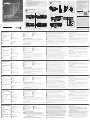
A
Hardware Review
KE9950T / KE9952T Front View
1
Audio Ports
2
KVM Ports
3
RS-232 Port
KE9950T / KE9952T Rear View
1
Grounding Terminal
2
Reset (Recessed Button)
3
Audio Ports
4
Power Jack
5
Function Switch
6
RS-232 Port
KE9950R / KE9952R Front View
1
Power LED
2
LAN LED
3
Local LED
4
Remote LED
KE9950R / KE9952R Rear View
1
Grounding Terminal
2
Reset (Recessed Button)
3
Audio Ports
4
USB Port (Peripheral)
5
Power Jack
6
Function Switch
7
RS-232 Port
* This port is not available on KE9952T / KE9952R.
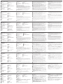
B
Hardware Installation
Use the screws provided with the mounting kit to screw the mounting bracket to the
bottom of the unit (Refer to the drawings shown above). For rack mounting, screw
the mounting bracket to any convenient location on the rack. For wall mounting, use
the mounting bracket’s center screw hole to mount the unit on a wall.
Note:
Rack screws are not provided to mount the unit. We recommend that you use
M5 x 12 Phillips type I cross screws.
Point-to-Point Installation
1
(Optional) Use the grounding wire to connect the extender’s grounding terminal to
a suitable grounded object.
2
On the transmitter side, plug the mouse, keyboard, DisplayPort monitor, and serial
devices into the ports on the Console section of the KE9950T / KE9952T.
3
Connect the DisplayPort cable and the USB 2.0 Type-A to Type-B cable provided with
this package into the KVM Ports on the front of the KE9950T / KE9952T.
4
Connect the other end of the DisplayPort cable and the USB 2.0 Type-A to Type-B
cable respectively into the video and USB ports on the computer.
5
For control of serial devices, connect the RS-232 port on the front of the transmitter
to a serial port on the computer.
6
Connect a Cat 5e/6 cable to the KE9950T / KE9952T’s LAN port.
7
On the receiver side, plug the mouse, keyboard, DisplayPort monitor, and serial
devices into the ports on the Console section of the KE9950R / KE9952R.
8
Connect the other end of the Cat 5e/6 cable to the KE9950R / KE9952R's LAN port.
9
Instead of connecting through the LAN ports, you can choose to connect the KE9950
/ KE9952 through the SFP slots. To do so, plug SFP modules into the transmitter and
receiver's SFP slots, then connect each end of Gigabit Ethernet (GbE) optical fi ber
between the SFP modules.**
10
Plug the power adapters into AC sources with the power cords and plug the other
ends into the transmitter and receiver’s power jacks respectively. The KE9952
supports Power over Ethernet (PoE) where power can be supplied through a PoE
network switch instead of using a power adapter.
11
(Optional) For power redundancy, plug the second power adapters into AC sources
with the power cords and plug the other ends into the transmitter and receiver’s
second power jacks respectively.***
12
Power on the computer.
**The SFP module 2A-136G / 2A-137G is sold separately. Contact your ATEN dealer for product
information.
*** The second power jacks are available on KE9950T and KE9950R only. The second power
adapter with the power cord is sold separately. Contact your ATEN dealer for product
information. Power redundancy for KE9952T and KE9952R can be achieved with the PoE
function.
OSD Options
Both the transmitter and receiver units are confi gured from the OSD menu on the
receiver. To invoke the OSD, either press the front panel OSD pushbutton (receiver
only), or tap the [Scroll Lock] key twice. The password to enter the OSD confi guration
screens is: password. The username / password to enter the System Login page in
Matrix Mode is: administrator / password.
To exit the OSD, press the [Esc] key; click Logout or Back to Video from the OSD menu;
or return to the OSD Main menu and press the front panel OSD pushbutton.
Note: Download the KE series user manual from our website for detailed instructions:
www.aten.com.
KE9950 4K DisplayPort KVM over IP Extender / KE9952 4K DisplayPort KVM over IP Extender (PoE)
www.aten.com
4
Remote / Local LED
5
LAN LED
6
Power LED
7
USB Ports (Console)
8
LAN Port
9
SFP Slot
10
DisplayPort Output (Console)
11
Power Jack (KE9950T only)*
5
Graphics Pushbutton
6
OSD Pushbutton
7
Video Pushbutton
8
USB Port (Peripheral)
B
Package Contents
1 KE9950T or KE9952T 4K DisplayPort KVM over IP Extender (Transmitter)
1 KE9950R or KE9952R 4K DisplayPort KVM over IP Extender (Receiver)
1 DisplayPort Cable (KE9950T / KE9952T only)
1 USB 2.0 Type-A to Type-B Cable (KE9950T / KE9952T only)
2 Power Adapters (KE9950T / KE9950R only)
2 Power Cords (KE9950T / KE9950R only)
1 Foot Pad Set (4 pcs.) for KE9950T or KE9952T
1 Mounting Kit for KE9950T or KE9952T
1 User Instructions
KE9950T / KE9952T Front View KE9950R / KE9952R Front View
Rack Mounting
Point-to-Point Installation
Wall Mounting
KE9950T / KE9952T Rear View KE9950R / KE9952R Rear View
Hardware Installation
© Copyright 2019 ATEN
®
International Co., Ltd.
ATEN and the ATEN logo are trademarks of ATEN International Co., Ltd. All rights reserved. All
other trademarks are the property of their respective owners.
This product is RoHS compliant.
Part No. PAPE-1223-Q30G Printing Date: 03/2019
4K DisplayPort KVM over IP Extender
4K DisplayPort KVM over IP Extender (PoE)
Quick Start Guide
KE9950 / KE9952
ATEN Altusen
™
4
1
2
3
7
8
5
6
5
2
3
4
8
9
10
11
6
7
1
7
5
6
2
8
9
10
11
3
4
1
12
*
21 3 4 5
6
32 4 5 6
1
5
2
3
4
7
8
6
1
9 10
6
4
5
2
7
8
3
1
9 10 11
*
M3 x 6
KE9950R (Rear)
KE9950T (Rear)
Cat 5e/6 cable
Optical Fiber Cable
KE9950T (Front)
5
2
3
4
7
10
6
9
Cat 5e/6 cable
Optical Fiber Cable
8
9
10
1
11
DC 5V
DC 5V
1
11
Serial
Device
Serial
Device
Support and Documentation Notice
All information, documentation, fi rmware,
software utilities, and specifi cations
contained in this package are subject to
change without prior notifi cation by
the manufacturer.
To reduce the environmental impact of our
products, ATEN documentation and software
can be found online at
http://www.aten.com/download/
Technical Support
www.aten.com/support
이 기기는 업무용(A급) 전자파적합기기로서 판매자 또는
사용자는 이 점을 주의하시기 바라며, 가정외의 지역에
서 사용하는 것을 목적으로 합니다.
Scan for
more information
EMC Information
FEDERAL COMMUNICATIONS COMMISSION INTERFERENCE
STATEMENT:
This equipment has been tested and found to comply with the limits
for a Class A digital device, pursuant to Part 15 of the FCC Rules.
These limits are designed to provide reasonable protection against
harmful interference when the equipment is operated in a commercial
environment. This equipment generates, uses, and can radiate radio
frequency energy and, if not installed and used in accordance with
the instruction manual, may cause harmful interference to radio
communications. Operation of this equipment in a residential area
is likely to cause harmful interference in which case the user will be
required to correct the interference at his own expense.
FCC Caution: Any changes or modifi cations not expressly approved by
the party responsible for compliance could void the user's authority to
operate this equipment.
Warning: Operation of this equipment in a residential environment
could cause radio interference.
This device complies with Part 15 of the FCC Rules. Operation is subject
to the following two conditions:(1) this device mat not cause harmful
interference, and(2) this device must accept any interference received,
including interference that may cause undesired operation.
A
Hardware Review
8
USB Ports (Console)
9
LAN Port
10
SFP Slot
11
DisplayPort Output (Console)
12
Power Jack (KE9950R only)*
* This port is not available on KE9952T/KE9952R.
La página se está cargando ...
Transcripción de documentos
Package Contents B 1 KE9950T or KE9952T 4K DisplayPort KVM over IP Extender (Transmitter) 1 KE9950R or KE9952R 4K DisplayPort KVM over IP Extender (Receiver) 1 DisplayPort Cable (KE9950T / KE9952T only) 1 USB 2.0 Type-A to Type-B Cable (KE9950T / KE9952T only) 2 Power Adapters (KE9950T / KE9950R only) 2 Power Cords (KE9950T / KE9950R only) 1 Foot Pad Set (4 pcs.) for KE9950T or KE9952T 1 Mounting Kit for KE9950T or KE9952T 1 User Instructions A Rack Mounting M3 x 6 www.aten.com/support KE9950R / KE9952R Front View 6 1 1 2 Scan for more information 3 4 Point-to-Point Installation KE9950 / KE9952 Cat 5e/6 cable 4K DisplayPort KVM over IP Extender 4K DisplayPort KVM over IP Extender (PoE) Quick Start Guide 1 2 2 3 5 3 5 4 4 6 5 6 8 7 KE9950T / KE9952T Rear View KE9950R / KE9952R Rear View 1 2 4 3 6 1 2 4 6 3 6 9 Optical Fiber Cable KE9950T (Front) 1 DC 5V 7 4 KE9950T (Rear) 2 8 9 Optical Fiber Cable 1 other trademarks are the property of their respective owners. 11 This product is RoHS compliant. 3 2 5 4 5 6 7 8 9 * 10 11 3 2 6 5 5 7 8 9 10 11 10 * 12 DC 5V 5 3 Serial Device Cat 5e/6 cable ATEN and the ATEN logo are trademarks of ATEN International Co., Ltd. All rights reserved. All EMC Information 11 10 Printing Date: 03/2019 All information, documentation, firmware, software utilities, and specifications contained in this package are subject to change without prior notification by the manufacturer. To reduce the environmental impact of our products, ATEN documentation and software can be found online at http://www.aten.com/download/ Technical Support ATEN Altusen™ Part No. PAPE-1223-Q30G Wall Mounting Hardware Review KE9950T / KE9952T Front View © Copyright 2019 ATEN® International Co., Ltd. Support and Documentation Notice Hardware Installation 7 4 FEDERAL COMMUNICATIONS COMMISSION INTERFERENCE STATEMENT: This equipment has been tested and found to comply with the limits for a Class A digital device, pursuant to Part 15 of the FCC Rules. These limits are designed to provide reasonable protection against harmful interference when the equipment is operated in a commercial environment. This equipment generates, uses, and can radiate radio frequency energy and, if not installed and used in accordance with the instruction manual, may cause harmful interference to radio communications. Operation of this equipment in a residential area is likely to cause harmful interference in which case the user will be required to correct the interference at his own expense. FCC Caution: Any changes or modifications not expressly approved by the party responsible for compliance could void the user's authority to operate this equipment. Warning: Operation of this equipment in a residential environment could cause radio interference. This device complies with Part 15 of the FCC Rules. Operation is subject to the following two conditions:(1) this device mat not cause harmful interference, and(2) this device must accept any interference received, including interference that may cause undesired operation. KE9950R (Rear) 이 기기는 업무용(A급) 전자파적합기기로서 판매자 또는 사용자는 이 점을 주의하시기 바라며, 가정외의 지역에 서 사용하는 것을 목적으로 합니다. Serial Device * This port is not available on KE9952T/KE9952R. KE9950 4K DisplayPort KVM over IP Extender / KE9952 4K DisplayPort KVM over IP Extender (PoE) A Hardware Review KE9950T / KE9952T Front View KE9950R / KE9952R Rear View 1 1 4 2 2 5 3 Remote / Local LED LAN LED 6 Power LED Audio Ports KVM Ports 3 RS-232 Port 2 3 4 5 6 Grounding Terminal Reset (Recessed Button) Audio Ports Power Jack Function Switch RS-232 Port 4 5 KE9950T / KE9952T Rear View 1 www.aten.com 6 USB Ports (Console) LAN Port 9 SFP Slot 10 DisplayPort Output (Console) 11 Power Jack (KE9950T only)* 7 8 KE9950R / KE9952R Front View Graphics Pushbutton OSD Pushbutton 7 Video Pushbutton 8 USB Port (Peripheral) 5 Power LED 2 LAN LED 3 Local LED 4 Remote LED 1 6 7 Grounding Terminal Reset (Recessed Button) Audio Ports USB Port (Peripheral) Power Jack Function Switch RS-232 Port 2 8 9 10 11 12 USB Ports (Console) LAN Port SFP Slot DisplayPort Output (Console) Power Jack (KE9950R only)* 4 5 6 7 * This port is not available on KE9952T / KE9952R. B 3 Hardware Installation Use the screws provided with the mounting kit to screw the mounting bracket to the bottom of the unit (Refer to the drawings shown above). For rack mounting, screw the mounting bracket to any convenient location on the rack. For wall mounting, use the mounting bracket’s center screw hole to mount the unit on a wall. Note: Rack screws are not provided to mount the unit. We recommend that you use 8 9 10 M5 x 12 Phillips type I cross screws. Point-to-Point Installation 1 (Optional) Use the grounding wire to connect the extender’s grounding terminal to a suitable grounded object. 11 On the transmitter side, plug the mouse, keyboard, DisplayPort monitor, and serial devices into the ports on the Console section of the KE9950T / KE9952T. Connect the DisplayPort cable and the USB 2.0 Type-A to Type-B cable provided with this package into the KVM Ports on the front of the KE9950T / KE9952T. Connect the other end of the DisplayPort cable and the USB 2.0 Type-A to Type-B cable respectively into the video and USB ports on the computer. For control of serial devices, connect the RS-232 port on the front of the transmitter to a serial port on the computer. Connect a Cat 5e/6 cable to the KE9950T / KE9952T’s LAN port. On the receiver side, plug the mouse, keyboard, DisplayPort monitor, and serial devices into the ports on the Console section of the KE9950R / KE9952R. Connect the other end of the Cat 5e/6 cable to the KE9950R / KE9952R's LAN port. Instead of connecting through the LAN ports, you can choose to connect the KE9950 / KE9952 through the SFP slots. To do so, plug SFP modules into the transmitter and receiver's SFP slots, then connect each end of Gigabit Ethernet (GbE) optical fiber between the SFP modules.** Plug the power adapters into AC sources with the power cords and plug the other ends into the transmitter and receiver’s power jacks respectively. The KE9952 supports Power over Ethernet (PoE) where power can be supplied through a PoE network switch instead of using a power adapter. (Optional) For power redundancy, plug the second power adapters into AC sources with the power cords and plug the other ends into the transmitter and receiver’s second power jacks respectively.*** 12 Power on the computer. **The SFP module 2A-136G / 2A-137G is sold separately. Contact your ATEN dealer for product information. *** The second power jacks are available on KE9950T and KE9950R only. The second power adapter with the power cord is sold separately. Contact your ATEN dealer for product information. Power redundancy for KE9952T and KE9952R can be achieved with the PoE function. OSD Options Both the transmitter and receiver units are configured from the OSD menu on the receiver. To invoke the OSD, either press the front panel OSD pushbutton (receiver only), or tap the [Scroll Lock] key twice. The password to enter the OSD configuration screens is: password. The username / password to enter the System Login page in Matrix Mode is: administrator / password. To exit the OSD, press the [Esc] key; click Logout or Back to Video from the OSD menu; or return to the OSD Main menu and press the front panel OSD pushbutton. Note: Download the KE series user manual from our website for detailed instructions: www.aten.com. Système d'extension 4K DisplayPort KVM sur IP KE9950 / Système d'extension 4K DisplayPort KVM sur IP KE9952 (PoE) A Présentation du matériel Vue avant KE9950T / KE9952T 1 Ports audio 2 Ports KVM 3 Port RS-232 LED A Distance / Local 5 LED LAN 6 LED d'alimentation 4 Vue arrière KE9950T / KE9952T 1 Prise de terre 2 Restaurer (Bouton enfoncé) 3 Ports audio 7 4 Prise d'alimentation 5 Commutation de fonction 10 8 9 11 Ports USB (Console) Port LAN Socle SFP Sortie DisplayPort (Console) Fiche électrique (KE9950T seulement)* 6 Port RS-232 Vue avant KE9950R / KE9952R 1 LED d'alimentation 2 LED LAN 3 LED Local 4 LED A Distance www.aten.com Vue arrière KE9950R / KE9952R Bouton des Graphismes Bouton OSD 7 Bouton Vidéo 8 Port USB (Périphérique) 5 6 1 Prise de terre 2 Restaurer (Bouton enfoncé) 3 Ports audio 4 Port USB (Périphérique) 5 Prise d'alimentation 2 Sur le transmetteur, branchez la souris, le clavier, l’écran DisplayPort et les périphériques 8 Ports USB (Console) 9 Port LAN 10 Socle SFP 11 Sortie DisplayPort (Console) 12 Fiche électrique (KE9950R seulement)* 6 Commutation de fonction 7 Port RS-232 * Ce port n’est pas disponible avec KE9952T / KE9952R. B Installation matérielle Utilisez les vis fournies avec le kit de montage pour visser le support de montage au bas de l'appareil (Reportez-vous aux dessins ci-dessus). Pour un montage sur un rack, vissez le support de montage dans un quelconque emplacement pratique sur le rack. Pour un montage sur un mur, utilisez le trou de vis central du support de montage pour monter l'appareil sur un mur. sériels dans les ports sur la section Console du KE9950T / KE9952T. 3 Connectez le câble DisplayPort et le câble USB 2.0 Type-A vers Type-B équipé avec cet emballage dans les ports KVM sur l’avant du KE9950T / KE9952T. 4 Connectez l’autre extrémité du câble DisplayPort et le câble USB 2.0 Type-A vers Type-B respectivement dans les ports vidéo et USB sur l’ordinateur. 5 Pour contrôler les périphériques sériels, connectez le port RS-232 sur l’avant du transmetteur à un port sériel sur l’ordinateur. 6 Connectez un câble Cat 5e/6 sur le port LAN du KE9950T / KE9952T. 7 Sur le récepteur, branchez la souris, le clavier, l’écran DisplayPort et les périphériques 8 9 10 Remarque : Les vis de rack ne sont pas fournies pour monter l'appareil. Nous vous recommandons d'utiliser des vis cruciformes de type I M5 x 12 Phillips. Installation Point-à-Point 11 1 (Optionnel) Utilisez le câble de terre pour connecter la borne de terre à un objet mis à terre correctement. sériels dans les ports sur la section Console du KE9950R / KE9952R. Connectez l’autre extrémité du câble Cat 5e/6 au port LAN du KE9950R / KE9952R. Au lieu d’une connexion avec des ports LAN, vous pouvez choisir de connecter le KE9950 / KE9952 via les socles SFP. Pour faire cela, branchez les modules SFP dans les socles SFP du transmetteur et du récepteur, puis connectez chaque extrémité de la fibre optique Gigabit Ethernet (GbE) entre les modules SFP.** Branchez les adaptateurs électriques dans une source CA avec les câbles électriques et branchez les autres extrémités respectivement dans les fiches électriques du transmetteur et du récepteur. Le KE9952 supporte la fonction Power over Ethernet (PoE) avec laquelle de l’électricité peut être fournie via un réseau PoE au lieu d’utiliser un adaptateur électrique. (Optionnel) Pour la redondance électrique, branchez le second adaptateur électrique dans une source CA avec les câbles électriques et branchez les autres extrémités respectivement dans les fiches électriques du transmetteur et du récepteur.*** 12 Allumez l'ordinateur. ** Le module SFP 2A-136G / 2A-137G est vendu séparément. Contactez votre vendeur ATEN pour des informations sur le produit. *** Une seconde fiche électrique n’est disponible que sur le KE9950T et le KE9950R uniquement. Le second adaptateur de secteur avec le cordon d’alimentation est vendu séparément. Contactez votre vendeur ATEN pour des informations sur le produit. La redondance électrique pour KE9952T et KE9952R peut être atteinte avec la fonction PoE. Options OSD* Les unités du transmetteur et du récepteur sont configurées depuis le menu OSD sur le récepteur. Pour appeler l’OSD, pressez le bouton OSD du panneau avant (récepteur uniquement) ou tapotez deux fois sur la touche [Scroll Lock]. Le mot de passe pour entrer dans l’écran de configuration OSD est: Mot de passe. Le nom utilisateur/mot de passe pour entrer dans la page Connexion au Système dans le Mode Matrice est: administrateur / mot de passe. Pour quitter l’OSD, pressez la touche [Esc]; cliquez sur Déconnexion ou Retour à la Vidéo depuis le menu OSD; ou retournez au Menu Principal OSD. Remarque : Téléchargez le manuel utilisateur des séries KE depuis notre site web pour des instructions détaillées. www.aten.com. KE9950 4K DisplayPort KVM over IP Extender / KE9952 4K DisplayPort KVM over IP Extender (PoE) A Hardware Übersicht KE9950T / KE9952T Ansicht von vorne 1 Audioanschlüsse 2 KVM-Anschlüsse 3 RS-232 Anschluss Fernsteuerung / Lokal LED 5 LAN LED 6 Netz-LED 4 KE9950T / KE9952T Ansicht von hinten 1 Erdungsanschluss 2 Reset (vertiefte Taste) 7 3 Audioanschlüsse 4 Netzbuchse 9 5 Funktionsschalter 6 RS-232 Anschluss 8 10 11 USB-Anschlüsse (Konsole) LAN Port SFP-Steckplatz DisplayPort Ausgang (Konsole) Netzanschluss (nur KE9950T)* KE9950R / KE9952R Ansicht von vorne 1 Netz-LED 2 LAN LED 3 Lokal LED 4 Fernsteuerung LED Grafik Drucktaste 6 OSD Drucktaste 7 Video Drucktaste 8 USB-Anschlüsse (Peripheriegeräte) 5 www.aten.com KE9950R / KE9952R Ansicht von hinten 2 Schließen Sie auf der Senderseite Maus, Tastatur, DisplayPort Monitor und serielle Geräte an die Anschlüsse am Konsolenteil des KE9950T / KE9952T an. 1 Erdungsanschluss 2 Reset (vertiefte Taste) 8 USB-Anschlüsse (Konsole) 9 LAN Port 3 Schließen Sie das mit diesem Paket mitgelieferte DisplayPort Kabel und das USB 2.0 3 Audioanschlüsse 4 USB-Anschlüsse (Peripheriegeräte) 10 SFP-Steckplatz 11 DisplayPort Ausgang (Konsole) 12 Netzanschluss (nur KE9950R)* 4 5 Netzbuchse 6 Funktionsschalter 7 RS-232 Anschluss * Dieser Anschluss ist bei KE9952T / KE9952R nicht verfügbar. B Hardwareinstallation Verwenden Sie die mit dem Montageset gelieferten Schrauben, um die Montagehalterung an der Unterseite des Geräts zu befestigen (siehe Zeichnungen oben). Befestigen Sie die Montagehalterung für die Rack-Montage mittels Schrauben an einer geeigneten Stelle im Rack. Verwenden Sie die mittlere Schraubenbohrung der Montagehalterung für die Wandmontage, um das Gerät an einer Wand zu befestigen. Hinweis: Für die Montage des Geräts werden keine Rackschrauben mitgeliefert. Wie 5 6 7 8 9 10 empfehlen, Kreuzschlitzschrauben M5 x 12 Phillips Typ I zu verwenden. Punkt-zu-Punkt-Installation 1 (Optional) Verwenden Sie das Erdungskabel, um die Erdungsklemme des Extenders mit 11 einem geeigneten geerdeten Objekt zu verbinden. Typ-A auf Typ-B Kabel an die KVM-Anschlüsse an der Vorderseite des KE9950T / KE9952T an. Schließen Sie das andere Ende des DisplayPort Kabels und das USB 2.0 Typ-A auf Typ-B Kabels jeweils an die Video- und USB-Anschlüsse des Computers an. Zur Steuerung serieller Geräte verbinden Sie die RS-232 Schnittstelle an der Vorderseite des Senders mit einer seriellen Schnittstelle des Computers. Schließen Sie ein Cat 5e/6-Kabel an den LAN-Anschluss des KE9950T / KE9952T an. Schließen Sie auf der Empfängerseite Maus, Tastatur, DisplayPort Monitor und serielle Geräte an die Anschlüsse am Konsolenteil des KE9950R / KE9952R an. Schließen Sie das andere Ende des Cat 5e/6 Kabels an den LAN-Anschluss des KE9950R / KE9952R an. Anstatt über die LAN-Anschlüsse zu verbinden, können Sie den KE9950 / KE9952 auch über die SFP-Steckplätze anschließen. Stecken Sie dazu SFP-Module in die SFPSteckplätze des Senders und des Empfängers und verbinden Sie dann jedes Ende der optischen Gigabit Ethernet (GbE) Glasfaser zwischen den SFP-Modulen.** Schließen Sie die Netzteile mit den Netzkabeln an die Wechselstromquellen an und stecken Sie dann die anderen Enden in die Netzbuchsen des Senders bzw. des Empfängers. Der KE9952 unterstützt Power over Ethernet (PoE), womit die Stromversorgung über ein PoE-Netzwerkswitch anstatt eines Netzteils erfolgen kann. (Optional) Für Netzredundanz schließen Sie die zweiten Netzteile mit den Netzkabeln an Wechselstromquellen an und stecken Sie dann die anderen Enden jeweils in die zweiten Netzbuchsen des Senders und des Empfängers.*** 12 Schalten Sie den Computer ein. ** Das SFP-Modul 2A-136G / 2A-137G wird separat verkauft. Wenden Sie sich für Produktinformationen an Ihren ATEN Händler. *** Die zweiten Netzbuchsen sind nur beim KE9950T und KE9950R verfügbar. Das zweite Netzteil mit dem Netzkabel wird separat verkauft. Wenden Sie sich für Produktinformationen an Ihren ATEN Händler. Die Stromredundanz für KE9952T und KE9952R kann mit der PoEFunktion erreicht werden. OSD-Optionen Sowohl die Transmitter- als auch die Empfängereinheit werden über das OSD-Menü am Empfänger konfiguriert. Um das OSD aufzurufen, drücken Sie entweder die OSD-Taste auf der Vorderseite (nur Empfänger) oder tippen Sie zweimal auf die Taste [Rollen]. Das Passwort für den Zugang zu den OSD-Konfigurationsbildschirmen lautet: password. Der Benutzername / das Passwort für den Zugang zur System Anmeldeseite im Matrix-Modus lautet: administrator / password. Um das OSD zu verlassen, drücken Sie die Taste [Esc], klicken Sie im OSD-Menü auf Abmelden oder Zurück zu Video oder kehren Sie zum OSD-Hauptmenü zurück und drücken Sie die OSD-Taste an der Vorderseite. Hinweis: Laden Sie das Benutzerhandbuch für die KE Serie von unserer Webseite herunter, um detaillierte Anweisungen zu erhalten: www.aten.com. Extensor DisplayPort KVM sobre IP KE9950 4K / Extensor DisplayPort KVM sobre IP KE9952 4K (PoE) A Revisión del hardware Vista frontal del KE9950T / KE9952T 1 Puertos de audio 2 Puertos KVM 3 Puerto RS-232 Vista posterior del KE9950R / KE9952R LED remoto / local LED LAN 6 LED de alimentación 4 5 Vista posterior del KE9950T / KE9952T 1 Terminal de conexión a tierra 2 Restablecer (botón empotrado) 3 Puertos de audio 4 Conector de alimentación 5 Interruptor de funciones 6 Puerto RS-232 Puertos USB (consola) Puerto LAN 9 Ranura SFP 10 Salida de DisplayPort (consola) 11 Clavija de alimentación (sólo KE9950T)* 7 8 Vista frontal del KE9950R / KE9952R 1 LED de alimentación 2 LED LAN 3 LED local 4 LED remoto www.aten.com Botón de Gráficos 6 Botón del OSD 7 Botón de Vídeo 8 Puerto USB (periférico) 5 1 Terminal de conexión a tierra 2 Restablecer (botón empotrado) 8 Puertos USB (consola) 9 Puerto LAN 3 Puertos de audio 4 Puerto USB (periférico) 10 Ranura SFP 11 Salida de DisplayPort (consola) 12 Clavija de alimentación (sólo KE9950R)* 5 Conector de alimentación 6 Interruptor de funciones 7 Puerto RS-232 * Este puerto no está disponible en el KE9952T / KE9952R. B Instalación del hardware Utilice los tornillos provistos con el kit de montaje para atornillar el soporte de montaje a la parte inferior de la unidad (consulte los dibujos que se muestran arriba). Para el montaje en bastidor atornille el soporte de montaje a cualquier parte del bastidor. Para el montaje en la pared utilice el orificio de tornillo central del soporte de montaje para montar la unidad en una pared. 2 En el lado del transmisor, conecte el ratón, el teclado, el monitor DisplayPort y los 3 4 5 6 7 8 9 10 Nota: Los tornillos del bastidor para montar la unidad no están incluidos. Recomendamos que utilice tornillos transversales Phillips M5 x 12 tipo I. Instalación punto a punto 11 1 (Opcional) Utilice el cable de conexión a tierra para conectar el terminal de conexión a dispositivos serie a los puertos en la sección Consola del KE9950T / KE9952T. Conecte el cable DisplayPort y el cable USB 2.0 tipo A a tipo B incluido en este paquete en los puertos KVM de la parte frontal del KE9950T / KE9952T. Conecte el otro extremo del cable DisplayPort y el cable USB 2.0 tipo A a tipo B en los puertos de vídeo y USB del ordenador respectivamente. Para controlar dispositivos en serie, conecte el puerto RS-232 de la parte frontal del transmisor a un puerto serie del ordenador. Conecte un cable Cat 5e/6 al puerto LAN del KE9950T / KE9952T. En el lado del receptor, conecte el ratón, el teclado, el monitor DisplayPort y los dispositivos serie a los puertos en la sección Consola del KE9950R / KE9952R. Conecte el otro extremo del cable Cat 5e/6 al puerto LAN del KE9950R / KE9952R. En lugar de conectar a través de los puertos LAN, puede elegir conectar el KE9950 / KE9952 a través de las ranuras SFP. Para hacerlo, conecte los módulos SFP en las ranuras SFP del transmisor y el receptor, luego conecte cada extremo de la fibra óptica Gigabit Ethernet (GbE) entre los módulos SFP.** Conecte los adaptadores de alimentación a las fuentes de CA con los cables de alimentación y conecte los otros extremos a los conectores de alimentación del transmisor y del receptor respectivamente. El KE9952 es compatible con Power over Ethernet (PoE) donde la alimentación se puede suministrar a través del conmutador de red PoE en lugar de usar un adaptador de alimentación. (Opcional) Para la redundancia de alimentación, conecte los segundos adaptadores de alimentación a las fuentes de CA con los cables de alimentación y conecte los otros extremos a los segundos enchufes de alimentación del transmisor y del receptor respectivamente.*** 12 Encienda el ordenador. ** El módulo SFP module 2A-136G / 2A-137G se vende por separado. Contacte con su vendedor ATEN para información sobre el producto. *** Los segundos enchufes de alimentación están disponibles sólo en el KE9950T y en el KE9950R. El segundo adaptador de corriente con el cable de alimentación se vende por separado. Contacte con su vendedor ATEN para información sobre el producto. La redundancia de potencia para el KE9952T y el KE9952R se puede lograr con la función PoE. Opciones del OSD Tanto el transmisor como el receptor se configuran desde el menú OSD del receptor. Para abrir el OSD, presione el botón OSD del panel frontal (solo receptor) o toque la tecla [Bloq Despl] dos veces. La contraseña para entrar en las pantallas de configuración del OSD es: contraseña. El nombre de usuario / contraseña para entrar en la página de inicio de sesión del sistema en el modo matriz es: administrador / contraseña. Para salir del OSD, presione la tecla [Esc]; haga clic en Logout (Cerrar sesión) o Back to Video (Volver al vídeo) desde el menú OSD; o regrese al menú principal del OSD y presione el botón del OSD del panel frontal. Nota: Descargue el manual de usuario de la serie KE de nuestro sitio web para obtener instrucciones detalladas: www.aten.com. tierra del extensor a un objeto conectado correctamente a tierra. KE9950 Estensore 4K DisplayPort KVM su IP / KE9952 Estensore 4K DisplayPort KVM su IP (PoE) A Revisione Hardware Vista anteriore del KE9950T / KE9952T 1 Porte audio 2 Porte KVM 3 Porta RS-232 LED remoto/locale LED LAN 6 LED accensione 4 5 Vista posteriore del KE9950T / KE9952T 1 Terminale di messa a terra 2 Ripristina (pulsante incassato) 3 Porte audio 4 Connettore d'alimentazione 5 Commutatore di funzioni 7 8 9 10 11 6 Porta RS-232 Porte USB (consolle) Porta LAN Slot SFP Uscita DisplayPort (Console) Connettore di alimentazione (solo KE9950T)* Vista anteriore del KE9950R / KE9952R 1 LED accensione 2 LED LAN 3 LED locale 4 LED remoto Pulsante modulo grafico Pulsante OSD 7 Pulsante video 8 Porta USB (periferiche) 5 www.aten.com Vista posteriore del KE9950R / KE9952R 1 Terminale di messa a terra 2 Ripristina (pulsante incassato) 8 Porte USB (consolle) 9 Porta LAN 3 Porte audio 4 Porta USB (periferiche) 10 Slot SFP 11 Uscita DisplayPort (Console) 12 Connettore di alimentazione (solo KE9950R)* 5 Connettore d'alimentazione 6 Commutatore di funzioni 7 Porta RS-232 * Questa porta non è disponibile sui modelli KE9952T / KE9952R. B Installazione dell'hardware Utilizzare le viti fornite con il kit di montaggio per avvitare la staffa di montaggio sul fondo dell'unità (fare riferimento ai disegni illustrati sopra). Per il montaggio su rack, avvitare la staffa di montaggio in qualsiasi posizione comoda sul rack. Per il montaggio a parete, utilizzare il foro della vite centrale della staffa di montaggio per montare l'unità su una parete. 2 Sul lato del trasmettitore, inserire il mouse, la tastiera, il monitor DisplayPort e i dispositivi seriali nelle porte della sezione Console del KE9950T / KE9952T. 3 Collegare il cavo DisplayPort e il cavo USB 2.0 tipo A al tipo B fornito con questo pacchetto nelle porte KVM sulla parte anteriore del KE9950T / KE9952T. 4 Collegare l'altra estremità del cavo DisplayPort e il cavo USB 2.0 tipo A al tipo B rispettivamente nelle porte video e USB del computer. 5 Per il controllo di dispositivi seriali, collegare la porta seriale RS-232 sulla parte anteriore del trasmettitore a una porta seriale del computer. 6 Collegare un cavo Cat 5e/6 alla porta LAN del KE9950T / KE9952T. 7 Sul lato del ricevitore, inserire il mouse, la tastiera, il monitor DisplayPort e i dispositivi 8 9 10 Nota: Per il montaggio dell'unità non sono fornite viti del rack. Si consiglia di utilizzare viti a croce M5 x 12 Phillips tipo I. 6 Installazione punto-punto 1 (Facoltativo) Usare un cavo di messa a terra per collegare il terminale di messa a terra 11 dell'estensore a un oggetto idoneo messo a terra. seriali nelle porte della sezione Console del KE9950R / KE9952R. Collegare l'altra estremità del cavo Cat 5e/6 alla porta LAN del KE9950R / KE9952R. Invece del collegamento tramite porte LAN, è possibile scegliere di collegare il KE9950 / KE9952 tramite gli slot SFP. A tal fine, inserire i moduli SFP negli slot SFP del trasmettitore e del ricevitore, quindi collegare ciascuna estremità della fibra ottica Gigabit Ethernet (GbE) ai moduli SFP.** Inserire gli adattatori di alimentazione nelle fonti di alimentazione CA con i cavi di alimentazione e collegare l'altra estremità agli jack di alimentazione del trasmettitore e del ricevitore, rispettivamente. Il KE9952 supporta Power over Ethernet (PoE), pertanto l'alimentazione può essere fornita tramite commutatore di rete PoE, senza dover usare un adattatore di alimentazione. (Facoltativo) Per l'alimentazione ridondante, inserire il secondo adattatore di alimentazione nelle fonti di alimentazione CA con i cavi di alimentazione e inserire l'altra estremità ai secondi jack di alimentazione del trasmettitore e del ricevitore.*** 12 Accendere il computer. ** Il modulo SFP 2A-136G / 2A-137G viene venduto separatamente. Per informazioni sul prodotto, contattare il rivenditore ATEN. *** I secondi jack di alimentazione sono disponibili solo sui modelli KE9950T e KE9950R. Il secondo adattatore di corrente con il cavo di alimentazione viene venduto separatamente. Per informazioni sul prodotto, contattare il rivenditore ATEN. È possibile ottenere l'alimentazione ridondante per KE9952T e KE9952R con la funzione PoE. Opzioni OSD Entrambe le unità trasmettitore e ricevitore sono configurate dal menu OSD sul ricevitore. Per richiamare l'OSD, premere il pulsante OSD sul pannello anteriore (solo per il ricevitore) oppure toccare il tasto [Scroll Lock] due volte. La password per accedere alle schermate di configurazione OSD è: password. Il nome utente / password per accedere alla pagina di accesso al sistema in modalità Matrix sono: amministratore / password. Per uscire dall'OSD, premere il tasto [Esc]; fare clic su Disconnetti o Torna al video dal menu OSD; o tornare al menu principale OSD. Quindi premere il pulsante OSD sul pannello anteriore. Nota: Per le istruzioni dettagliate, scaricare il manuale utente della serie KE dal nostro sito Web: www.aten.com. KE9950 4K DisplayPort KVM-удлинитель по IP / KE9952 4K DisplayPort KVM-удлинитель по IP (PoE) A Обзор оборудования Передняя панель KE9950T / KE9952T 1 Аудио порты 2 Порты KVM 3 Порт RS-232 Индикаторы удаленного/локального режима 5 Индикатор LAN 6 Индикатор питания 4 Задняя панель KE9950T / KE9952T 1 Контакт заземления 7 2 Кнопка сброса (утопленная кнопка) 8 3 Аудио порты 9 4 Разъем питания 10 5 Переключатель функций 6 Порт RS-232 USB-порты (консоль) Порт LAN Слот SFP Выход DisplayPort (консоль) 11 Разъём питания (только KE9950T)* Передняя панель KE9950R / KE9952R 1 Индикатор питания 2 Индикатор LAN 3 Индикатор локального режима 4 Индикатор удаленного режима Кнопка графики 6 Кнопка OSD 7 Кнопка видео 8 Порт USB (периферийный) 5 www.aten.com Задняя панель KE9950R / KE9952R 1 Контакт заземления 8 2 Кнопка сброса (утопленная кнопка) 9 3 Аудио порты 10 4 Порт USB (периферийный) 11 5 Разъем питания 6 Переключатель функций USB-порты (консоль) Порт LAN Слот SFP Выход DisplayPort (консоль) 12 Разъём питания (только KE9950R)* 7 Порт RS-232 * В устройствах KE9952T/KE9952R этот порт отсутствует. B Установка оборудования Винтами из монтажного комплекта прикрепите монтажный кронштейн к нижней части устройства (как показано на схеме выше). Для стоечного монтажа: привинтите монтажный кронштейн к стойке в любом удобном месте. Для настенного монтажа: прикрепите устройство к стене через центральное отверстие в монтажном кронштейне. Примечание: Винты для монтажа в стойку не входят в комплект поставки 2 На стороне передатчика: подсоедините мышь, клавиатуру, монитор DisplayPort 3 4 5 6 7 8 9 10 устройства. Мы рекомендуем использовать крестовые винты Phillips M5 x 12 мм типа I. Установка соединения «точка-точка» 1 (Дополнительно) Подсоедините контакт заземления на удлинителе к подходящему заземленному объекту с помощью заземляющего провода. 11 и последовательные устройства к портам консольной части KE9950T / KE9952T. Подсоедините прилагаемые кабели DisplayPort и USB 2.0 «Type-A—Type-B» к портам KVM на передней панели KE9950T / KE9952T. Подсоедините противоположные концы кабелей DisplayPort и USB 2.0 «Type-A— Type-B» соответственно к портам видео и USB на компьютере. Для управления последовательными устройствами подключите разъем RS-232 на передней панели передатчика к последовательному порту компьютера. Подсоедините кабель Cat 5e/6 к порту LAN на KE9950T / KE9952T. На стороне передатчика: подсоедините мышь, клавиатуру, монитор DisplayPort и последовательные устройства к портам консольной части KE9950R / KE9952R. Подсоедините другой конец кабеля Cat 5e/6 к порту LAN на KE9950R / KE9952R. Instead of connecting through the LAN ports, you can choose to connect the KE9950 / KE9952 through the SFP slots. Вместо подключения по портам LAN можно соединить KE9950/KE9952, используя слоты SFP. Для этого установите в слоты SFP передатчика и приемника модули SFP, а затем соедините модули SFP оптоволоконным кабелем Gigabit Ethernet (GbE)**. Подсоедините адаптеры питания (со шнуром питания) к электророзеткам, а затем подключите выходы адаптеров к разъемам питания на передатчике и приемнике. Устройства KE9952 поддерживают подачу питания по Ethernet (PoE), поэтому питание может подаваться через сетевой коммутатор PoE без использования адаптера питания. (Дополнительно) Для организации резервного питания подсоедините дополнительные адаптеры питания (со шнуром питания) к электророзеткам, и подключите выходы адаптеров к дополнительным разъемам питания на передатчике и приемнике***. 12 Включите компьютер. ** SFP-модули 2A-136G/2A-137G продаются отдельно. Для получения сведений о продукции обращайтесь к местному дилеру ATEN. *** Дополнительные разъемы питания имеются только на устройствах KE9950T и KE9950R. Дополнительные адаптеры питания (со шнуром питания) продаются отдельно. Для получения сведений о продукции обращайтесь к местному дилеру ATEN. В качестве резервного источника питания для KE9952T и KE9952R можно использовать питание PoE. Свойства экранного меню Настройка приемника и передатчика осуществляется из экранного меню приемника. Чтобы вызвать экранное меню, нажмите кнопку OSD на передней панели (только приемник) либо дважды нажмите клавишу [Scroll Lock]. Пароль для входа в выбранное меню настройки: password. Имя пользователя и пароль, вводимые на странице «Вход в систему» в режиме матрицы: administrator / password. Для выхода из экранного меню нажмите [ESC], а затем выберите «Выход» или «Назад к видео», либо вернитесь в главное меню и нажмите кнопку OSD на передней панели. Примечание: Для получения дополнительных сведений загрузите руководство пользователя устройств серии KE с сайта: www.aten.com.-
 1
1
-
 2
2


ATEN KE9950R Guía de inicio rápido
- Tipo
- Guía de inicio rápido
En otros idiomas
- français: ATEN KE9950R Guide de démarrage rapide
- italiano: ATEN KE9950R Guida Rapida
- English: ATEN KE9950R Quick start guide
- Deutsch: ATEN KE9950R Schnellstartanleitung
- русский: ATEN KE9950R Инструкция по началу работы
- português: ATEN KE9950R Guia rápido
- polski: ATEN KE9950R Skrócona instrukcja obsługi
- 日本語: ATEN KE9950R クイックスタートガイド
- Türkçe: ATEN KE9950R Hızlı başlangıç Kılavuzu
Documentos relacionados
-
ATEN KE6910R Guía de inicio rápido
-
ATEN KE8950 Guía de inicio rápido
-
ATEN KE6920T Guía de inicio rápido
-
ATEN KE6900AiT Guía de inicio rápido
-
ATEN KE6900AR Guía de inicio rápido
-
ATEN KE9900ST Guía de inicio rápido
-
ATEN KE6900T Guía de inicio rápido
-
ATEN KE6900 Guía de inicio rápido
-
ATEN KX9970 Guía de inicio rápido
-
ATEN VB905 Guía de inicio rápido
