
© Copyright 2019 ATEN
®
International Co., Ltd.
ATEN and the ATEN logo are trademarks of ATEN International Co., Ltd. All rights reserved.
All other trademarks are the property of their respective owners.
Part No. PAPE-1223-S30G Printing Date: 11/2019
DVI-I Single Display KVM over IP Extender /
DVI-I Dual Display KVM over IP Extender
Quick Start Guide
KE6900A / KE6940A
ATEN Altusen
™
Support and Documentation Notice
All information, documentation, fi rmware,
software utilities, and specifi cations contained in
this package are subject to change without prior
notifi cation by the manufacturer.
To reduce the environmental impact of our
products, ATEN documentation and software can
be found online at
http://www.aten.com/download/
Technical Support
www.aten.com/support
이 기기는 업무용(A급) 전자파적합기기로서 판매자 또는 사용자는 이 점을
주의하시기 바라며, 가정외의 지역에서 사용하는 것을 목적으로 합니다.
Scan for
more information
EMC Information
FEDERAL COMMUNICATIONS COMMISSION INTERFERENCE
STATEMENT:
This equipment has been tested and found to comply with the limits
for a Class A digital device, pursuant to Part 15 of the FCC Rules.
These limits are designed to provide reasonable protection against
harmful interference when the equipment is operated in a commercial
environment. This equipment generates, uses, and can radiate radio
frequency energy and, if not installed and used in accordance with
the instruction manual, may cause harmful interference to radio
communications. Operation of this equipment in a residential area
is likely to cause harmful interference in which case the user will be
required to correct the interference at his own expense.
FCC Caution: Any changes or modifi cations not expressly approved by
the party responsible for compliance could void the user's authority to
operate this equipment.
Warning: Operation of this equipment in a residential environment
could cause radio interference.
This device complies with Part 15 of the FCC Rules. Operation is subject
to the following two conditions:(1) this device mat not cause harmful
interference, and(2) this device must accept any interference received,
including interference that may cause undesired operation.
Important. Before proceeding, download the Installation and
Operation Manual by visiting the website, www.aten.com and
navigating to the product page. The manual includes important
warnings, loading specifi cations and grounding instructions.
A
Description de l’appareil
KE6900AT / KE6940AT Vue de face
1
Ports audio
2
Ports KVM
3
Port RS-232
KE6900AT / KE6940AT Vue arrière
1
Prise terre
2
Réinitialisation (Bouton encastré)
3
Ports audio
4
Port LAN
5
Prise d’alimentation
6
Fonction de commutateur
Remarque : Les faces avant et arrière du KE6940AT sont présentées ci-dessus. Les faces
avant et arrière du KE6900AT sont identiques à celles du KE6940AT, sauf que
le KE6900AT à 1 port DVI-I plutôt que 2.
KE6900AR / KE6940AR Vue de face
1
Voyant d’alimentation
2
Voyant LAN
5
Bouton-poussoir des graphiques
6
Bouton-poussoir du menu de
l’affi chage à l’écran
KE6900AR / KE6940AR Vue arrière
1
Prise terre
2
Réinitialisation (Bouton encastré)
3
Ports audio
4
Port USB (Périphérique)
5
Port LAN
6
Prise d’alimentation
Remarque : Les faces avant et arrière du KE6940AR sont présentées ci-dessus. La face
avant du KE6900AR est identique à celle du KE6940AR. La face arrière du
KE6900AR est identique à celle du KE6940AR, sauf que le KE6900AR a
1 port DVI-I plutôt que 2.
B
Installation matérielle
Montage
Fixez le support
1
Dévissez les vis de l’unité comme indiqué ci-dessus.
2
Utilisez les vis de l’étape précédente pour visser le support de fi xation au bas
de l’extender comme décrit ci-dessus.
Montage en rack
Vissez le support dans un emplacement approprié sur le rack.
Montage mural
Utilisez le trou central pour visser le support sur une surface murale sécurisée.
Installation par points
1
(Facultatif) Connectez un fi l de terre entre la borne de terre de l’extender et
un objet approprié mis à la terre.
2
Du côté de l’émetteur, branchez la souris, le clavier, le moniteur DVI et
les périphériques série dans les ports de la section Console de l’émetteur
(KE6900AT / KE6940AT).
3
Branchez le câble DVI-D et le câble USB 2.0 Type-A au Type-B fourni avec
cet appareil dans les ports KVM sur la face de l’émetteur.
4
Branchez l’autre extrémité du câble USB DVI-D KVM dans les ports clavier,
vidéo, souris, haut-parleur et microphone de l’ordinateur.
5
Pour la commande des périphériques série, connectez le port RS-232 situé
sur la face avant de l’émetteur à un port série de l’ordinateur.
6
Branchez un câble Cat 5e / 6 dans le port LAN de l’émetteur.
Extension KVM sur IP affi chage simple DVI-I KE6900A / Extension KVM sur IP affi chage double DVI-I KE6940A
www.aten.com
7
Branchez la souris, le clavier, le moniteur DVI et les périphériques série dans
les ports de la partie console du récepteur (KE6900AR / KE6940AR).
8
Connectez l’autre bout du câble Cat 5e / 6 au port LAN du récepteur.
9
Au lieu de vous connecter via les ports LAN, vous pouvez choisir de vous
connecter via les logements SFP. Pour ce faire, connectez les modules SFP
aux logements SFP de l’émetteur et du récepteur, puis connectez chaque
bout de la fi bre optique Gigabit Ethernet (GbE) entre les modules SFP.*
10
Branchez les adaptateurs d’alimentation aux prises d’alimentation secteur
à l’aide les câbles d’alimentation et branchez l’autre bout sur les prises
d’alimentation de l’émetteur et du récepteur, respectivement.
11
(Facultatif) Pour assurer la redondance de l’alimentation, branchez les
deuxièmes adaptateurs d’alimentation à des sources d’alimentation secteur
à l’aide des câbles d’alimentation, puis branchez les autres bouts aux prises
d’alimentation de l’émetteur et du récepteur.
12
Allumez l’ordinateur.
*Le module SFP 2A-136G / 2A-137G est vendu séparément. Contactez votre
revendeur ATEN pour obtenir des informations sur le produit.
Options d’affi chage à l’écran
L’émetteur et le récepteur peuvent tous être confi gurés à partir des paramètres
du menu de l’affi chage à l’écran du récepteur. Pour la confi guration du
menu de l’affi chage à l’écran, reportez-vous au manuel d’utilisation KE
(téléchargeable sur www.aten.com).
4
Voyant distant / local
5
Voyant LAN
6
Voyant d’alimentation
3
Voyant local
4
Voyant distant
7
Bouton-poussoir vidéo
8
Port USB
7
Fonction de commutateur
8
Port RS-232
9
Ports USB (Console)
10
Logement SFP
11
Sortie DVI-I (Console)
12
Prise d’alimentation
7
Port RS-232
8
Ports USB (Console)
9
Logement SFP
10
Sortie DVI-I (Console)
11
Prise d’alimentation
A
Hardwareübersicht
KE6900AT / KE6940AT – Ansicht von vorn
1
Audioports
2
KVM-Ports
3
RS-232-Port
KE6900AT / KE6940AT – Ansicht von hinten
1
Erdungsklemme
2
Reset-Taste (versenkt)
3
Audioports
4
LAN-Port
5
Netzadapterbuchse
6
Funktionsumschalter
Hinweis: Vorstehend ist die Vorder- und Rückansicht des KE6940AT abgebildet. Die Vorder-
und Rückansicht des KE6900AT ist mit der Vorder- und Rückansicht des KE6940AT
identisch, allerdings besitzt der KE6900AT lediglich einen DVI-I-Port und nicht zwei.
KE6900AR / KE6940AR – Ansicht von vorn
1
Betriebszustands-LED
2
LAN-LED
5
Grafi k-Drucktaste
6
OSD-Drucktaste
KE6900AR / KE6940AR – Ansicht von hinten
1
Erdungsklemme
2
Reset-Taste (versenkt)
3
Audioports
4
USB-Port (Peripheriegerät)
5
LAN-Port
6
Netzadapterbuchse
Hinweis: Vorstehend ist die Vorder- und Rückansicht des KE6940AR abgebildet. Die
Vorderansicht des KE6900AR ist identisch der Vorderansicht des KE6940AR. Die
Rückansicht des KE6900AR ist mit der Rückansicht des KE6940AR identisch,
allerdings besitzt der KE6900AR lediglich einen DVI-I-Port und nicht zwei.
B
Installation der Hardware
Montage
Anbringen der Montageplatte
1
Lösen Sie die Schrauben vom Gerät, wie oben gezeigt.
2
Benutzen Sie die im vorherigen Schritt erhaltenen Schrauben, um die
Montageplatte wie in der vorstehenden Abbildung gezeigt an der Unterseite
des Extenders zu befestigen.
Rackmontage
Befestigen Sie die Montageplatte mit den Schrauben an der gewünschten
Rackposition.
Wandmontage
Verwenden Sie das Mittelloch, um die Montageplatte an einer sicheren
Wandoberfl äche festzuschrauben.
Punkt-zu-Punkt-Installation
1
(Optional) Verbinden Sie die Erdungsklemme des Extenders über eine
Erdungsleitung mit einem geeigneten geerdeten Gegenstand.
2
Schließen Sie auf der Senderseite Maus, Tastatur, DVI-Monitor und serielle
Geräte an den Ports des Konsolenbereichs der Sendeeinheit (KE6900AT/
KE6940AT) an.
3
Schließen Sie das im Lieferumfang enthaltene DVI-D- sowie das USB
2.0-Typ-A-auf-Typ-B-Kabel an den KVM-Ports auf der Vorderseite der
Sendeeinheit an.
4
Schließen Sie das andere Ende des USB DVI-D-KVM-Kabels am Tastatur-,
Video-, Maus-, Lautsprecher- und Mikrofonport des Computers an.
5
Verbinden Sie den RS-232-Port auf der Vorderseite der Sendeeinheit für die
Steuerung serieller Geräte mit dem seriellen Port des Computers.
6
Schließen Sie am LAN-Port der Sendeeinheit ein Cat5e/6-Kabel an.
KE6900A DVI-I Einzelanzeige KVM over IP Extender / KE6940A DVI-I Dual-Anzeige KVM over IP Extender
www.aten.com
7
Schließen Sie Maus, Tastatur, DVI-Monitor und serielle Geräte an den Ports
des Konsolenbereichs der Empfangseinheit (KE6900AR/KE6940AR) an.
8
Schließen Sie das andere Ende des Cat5e/6-Kabels am LAN-Port der
Empfangseinheit an.
9
Sie können die Extender anstelle über die LAN-Ports auch über die SFP-Schachte
verbinden. Stecken Sie hierfür jeweils ein SFP-Modul* in den SFB-Schacht der
Sende- und Empfangseinheit und verbinden Sie dann beide Module über ein
optisches Gigabit-Ethernet-Glasfaserkabel (GbE-Glasfaserkabel).*
10
Stecken Sie die Netzstecker der Netzadapter in jeweils eine Netzsteckdose
und die DC-Stecker in die jeweilige Netzadapterbuchse der Sende- und
Empfangseinheit.
11
(Optional) Stecken Sie für eine redundante Stromversorgung die Netzstecker
der Netzadapter in jeweils eine Netzsteckdose und die DC-Stecker in die
jeweilige Netzadapterbuchse der Sende- und Empfangseinheit.
12
Schalten Sie den Computer ein.
* Das SFP-Modul 2A-136G / 2A-137G ist als Zubehör erhältlich. Setzen Sie sich
bitte für Produktinformationen mit Ihrem/Ihrer ATEN-Händler/-in in Verbindung.
OSD-Optionen
Sowohl die Sende- als auch die Empfangseinheit kann über das OSD-Menü der
Empfangseinheit konfi guriert werden. Schlagen Sie bzgl. der OSD-Konfi guration in
der KE-Bedienungsanleitung (auf www.aten.com herunterladbar) nach.
4
Remote-/Lokal-LED
5
LAN-LED
6
Betriebszustands-LED
3
Lokal-LED
4
Remote-LED
7
Video-Drucktaste
8
USB-Port
7
Funktionsumschalter
8
RS-232-Port
9
USB-Ports (Konsole)
10
SFP-Schacht
11
DVI-I-Ausgang (Konsole)
12
Netzadapterbuchse
7
RS-232-Port
8
USB-Ports (Konsole)
9
SFP-Schacht
10
DVI-I-Ausgang (Konsole)
11
Netzadapterbuchse
A
Reseña del hardware
Vista frontal de los conmutadores KVM KE6900AT y KE6940AT
1
Puertos de audio
2
Puertos KVM
3
Puerto RS-232
Vista posterior de los conmutadores KVM KE6900AT y KE6940AT
1
Toma de tierra
2
Reinicio (botón encastrado)
3
Puertos de audio
4
Puerto LAN
5
Entrada de alimentación
6
Interruptor de función
Nota: las partes frontal y posterior del KE6940AT se muestran más arriba. Las partes
frontal y posterior del KE6900AT son iguales que las del KE6940AT excepto que el
KE6900AT tiene 1 puerto DVI-I en lugar de 2.
Vista frontal de los conmutadores KVM KE6900AR y KE6940AR
1
Indicador led de alimentación
2
Indicador led de la LAN
5
Botón de gráfi cos
6
Botón de visualización en pantalla (OSD)
Vista posterior de los conmutadores KVM KE6900AR y KE6940AR
1
Toma de tierra
2
Reinicio (botón encastrado)
3
Puertos de audio
4
Puerto USB (periférico)
5
Puerto LAN
6
Entrada de alimentación
Nota: Las partes frontal y posterior del KE6940AR se muestran en la fi gura superior. La parte
frontal del KE6900AR es igual que la del KE6940AR. La parte posterior del KE6900AR es
igual que la del KE6940AR excepto que el KE6900AR tiene 1 puerto DVI-I en lugar de 2.
B
Instalación del hardware
Montaje
de la chapa de suspensión
1
Extraiga los tornillos de la unidad de la forma indicada anteriormente.
2
Utilice los tornillos del paso anterior para atornillar la chapa de suspensión de
montaje en la parte inferior del expansor como se muestra en la fi gura superior.
Soporte para estantería
Atornille la chapa de suspensión en un lugar conveniente del soporte para estantería.
Montaje en pared
Utilice el agujero central para atornillar la chapa de suspensión en una
superfi cie mural segura.
Instalación de punto a punto
1
(Opcional) Conecte un cable de tierra entre la terminal de tierra del
expansor y un objeto debidamente conectado a tierra.
2
En el lado del transmisor, conecte el ratón, el teclado, el monitor DVI y
los dispositivos de serie en los puertos de la sección de la consola del
transmisor (KE6900AT/KE6940AT).
3
Conecte el cable DVI-D y el cable USB 2.0 tipo A a tipo B incluido en el
paquete a los puertos KVM en la parte frontal del transmisor.
4
Conecte el otro extremo del cable USB DVI-D KVM en los puertos de
teclado, vídeo, ratón, altavoz y micrófono del ordenador.
5
Para controlar los dispositivos de serie, conecte el puerto RS-232 en la parte
frontal del transmisor a un puerto serie del ordenador.
6
Conecte un cable Cat 5e/6 al puerto LAN del transmisor.
Extensor KVM sobre IP de pantalla única DVI-I KE6900A / Extensor KVM sobre IP de pantalla dual DVI-D KE6940A
www.aten.com
7
Conecte el ratón, el teclado, el monitor DVI y los dispositivos de serie a los
puertos de la sección de la consola del receptor (KE6900AR/KE6940AR).
8
Conecte el otro extremo del cable Cat 5e/6 al puerto LAN del receptor.
9
En lugar de conectarlos a través de los puertos LAN, puede optar por conectar
los expansores a través de las ranuras SFP. Para ello, conecte los módulos SFP
en las ranuras SFP del transmisor y el receptor y, luego, conecte cada extremo
de la fi bra óptica Gigabit Ethernet (GbE) entre los módulos SFP.*
10
Conecte los adaptadores de corriente a las tomas CA con los cables de
alimentación y conecte los otros extremos en las entradas de alimentación
del transmisor y el receptor respectivamente.
11
Opcionalmente, para una alimentación redundante, conecte los segundos
adaptadores de corriente a las tomas CA con los cables de alimentación y conecte
los otros extremos en las entradas de alimentación del transmisor y el receptor.
12
Encienda el ordenador.
* Los módulos SFP 2A-136G y 2A-137G se venden por separado. Contacte
con su distribuidor ATEN para obtener más información del producto.
Opciones de visualización en pantalla (OSD)
Tanto el transmisor como el receptor se pueden confi gurar mediante el menú
de visualización en pantalla (OSD) del receptor. Para la confi guración de la
visualización en pantalla, consulte el manual de usuario KE (se puede descargar
en www.aten.com).
4
Indicador led local/remoto
5
Indicador led de la LAN
6
Indicador led de alimentación
3
Indicador led local
4
Indicador led remoto
7
Botón de vídeo
8
Puerto USB
7
Interruptor de función
8
Puerto RS-232
9
Puertos USB (consola)
10
Ranura SFP
11
Salida DVI-I (consola)
12
Entrada de alimentación
7
Puerto RS-232
8
Puertos USB (consola)
9
Ranura SFP
10
Salida DVI-I (consola)
11
Entrada de alimentación
A
Panoramica hardware
Vista anteriore KE6900AT / KE6940AT
1
Porte audio
2
Porte KVM
3
Porta RS-232
Vista posteriore KE6900AT / KE6940AT
1
Terminale di messa a terra
2
Reset (Pulsante incassato)
3
Porte audio
4
Porta LAN
5
Presa di alimentazione
6
Commutatore di funzione
Nota: La parte anteriore e posteriore dell'unità KE6940AT sono mostrate sopra. La parte
anteriore e posteriore dell'unità KE6900AT sono uguali a quella del KE6940AT
tranne per il fatto che il KE6900AT ha 1 porta DVI-I anziché 2.
Vista anteriore KE6900AR / KE6940AR
1
LED di accensione
2
LED LAN
5
Pulsante grafi ci
6
Pulsante OSD
Vista posteriore KE6900AR / KE6940AR
1
Terminale di messa a terra
2
Reset (Pulsante incassato)
3
Porte audio
4
Porta USB (Periferica)
5
Porta LAN
6
Presa di alimentazione
Nota: La parte anteriore e posteriore dell'unità KE6940AR sono mostrate sopra. La parte
anteriore dell'unità KE6900AR è uguale a quella del KE6940AR. La parte posteriore
dell'unità KE6900AR è uguale a quella del KE6940AR tranne per il fatto che il
KE6900AR ha 1 porta DVI-I anziché 2.
B
Installazione hardware
Montaggio
Applicare la staffa
1
Allentare le viti dall'unità come mostrato in precedenza.
2
Usare le viti del passo precedente per avvitare la staffa di montaggio alla parte
inferiore dell'extender mostrato sopra.
Montaggio su rack
Avvitare la staffa in una posizione adatta sul rack.
Montaggio a parete
Usare il foro centrale per avvitare la staffa alla superfi cie di una parete solida.
Installazione punto-punto
1
(Opzionale) Collegare un cavo di messa a terra tra il terminale di messa a
terra dell’extender e un oggetto opportunamente collegato a terra.
2
Sul lato del trasmettitore, inserire mouse, tastiera, monitor DVI e
dispositivi seriali nelle porte della sezione Console del trasmettitore
(KE6900AT/KE6940AT).
3
Collegare il cavo DVI-D e il cavo USB 2.0 Tipo-A a Tipo-B incluso nella
confezione alle porte KVM nella parte anteriore del trasmettitore.
4
Collegare l'altra estremità del cavo KVM USB DVI-D alle porte di tastiera,
video, mouse, altoparlante e microfono del computer.
5
Per i dispositivi seriali di controllo, collegare la porta RS-232 sulla parte
anteriore del trasmettitore a una porta seriale del computer.
6
Collegare un cavo Cat 5e/6 alla porta LAN del trasmettitore.
7
Inserire mouse, tastiera, monitor DVI e dispositivi seriali nelle porte della
sezione Console del ricevitore (KE6900AR/KE6940AR).
Extender over IP a schermo singolo KVM KE6900A DVI-I / Extender over IP a schermo doppio KE6940A DVI-I
www.aten.com
8
Collegare l'altra estremità del cavo Cat 5e/6 alla porta LAN del ricevitore.
9
Invece di usare le porte LAN per la connessione, è possibile collegare gli
extender tramite gli slot SFP. A questo scopo, inserire i moduli SFP negli
slot SFP di trasmettitore e ricevitore, poi collegare ogni estremità della fi bra
ottica Gigabit Ethernet (GbE) tra i moduli SFP.*
10
Inserire gli adattatori di alimentazione alle prese CA con i cavi in dotazione
e inserire le altre estremità nelle prese di alimentazione di ricevitore e
trasmettitore rispettivamente.
11
(Opzionale) Per garantire la ridondanza di alimentazione, inserire i secondi
adattatori di alimentazione alle prese CA con i cavi in dotazione e inserire
le altre estremità nelle prese di alimentazione di ricevitore e trasmettitore
rispettivamente.
12
Accendere il computer.
*Il modulo SFP 2A-136G / 2A-137G è venduto a parte. Contattare il proprio
rivenditore ATEN per altre informazioni sul prodotto.
Opzioni OSD
Sia il trasmettitore che il ricevitore possono essere confi gurati dal menu OSD
del ricevitore. Per la confi gurazione OSD, consultare il manuale d'uso KE
(che può essere scaricato dal sito www.aten.com).
4
LED Remoto / Locale
5
LED LAN
6
LED di accensione
3
LED Locale
4
LED remoto
7
Pulsante Video
8
Porta USB
7
Commutatore di funzione
8
Porta RS-232
9
Porte USB (Console)
10
Slot SFP
11
Uscita DVI-I (Console)
12
Presa di alimentazione
7
Porta RS-232
8
Porte USB (Console)
9
Slot SFP
10
Uscita DVI-I (Console)
11
Presa di alimentazione
B
Hardware Installation
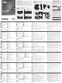
Package Contents
KE6900AT / KE6940AT Package Contents
1 KE6900AT DVI-I Single Display KVM over IP Transmitter / KE6940AT DVI-I Dual Display KVM over IP
Transmitter
1 Power Adapter & Power Cord
1 KVM Cable (DVI-D, USB, Audio; 1.8m/6ft)
1 DVI-D Cable 1.8 m (for KE6940AT)
KE6900AR / KE6940AR Package Contents
1 KE6900AR DVI-I Single Display KVM over IP Receiver / KE6940AR DVI-I Dual Display KVM over IP Receiver
1 Power Adapter & Power Cord
1 User Instructions
A
Hardware Review
1 Foot Pad Set (4 pcs.)
1 Mounting Kit
1 User Instructions
KE6900AT / KE6940AT Front View KE6900AR / KE6940AR Front View
KE6900AT / KE6940AT Rear View KE6900AR / KE6940AR Rear View
4
1
2
3
7
8
5
6
8
6
7
2
9
10 11 12
3
4
1
5
3 4 5 6
2
1
7
5
6
2
8
9
10 11
3
41
Rack Mount
Mounting
Attach Bracket
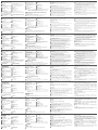
Point-to-Point Installation
Wall Mount
M3 x 5
1
2
KE6900AR (Rear)
KE6900AT (Rear)
Serial
Device
Serial
Device
Optical
Fiber
Cable
Optical
Fiber
Cable
Cat 5e cable
Cat 5e cable
KE6900AT (Front)
USB DVI-D KVM
cable
5
1
3
4
89
10
9 6
10
2
11
11
1
7
A
Обзор оборудования
Вид спереди: KE6900AT / KE6940AT
1
Аудио порты
2
Порты KVM
3
Порт RS-232
Вид сзади: KE6900AT / KE6940AT
1
Клемма заземления
2
Сброс (утопленная кнопка)
3
Аудио порты
4
LAN порт
5
Разъем питания
6
Переключатель режима работы
Примечание: На рисунке выше показаны передняя и задняя панели KE6940AT. Передняя и
задняя панели моделей KE6900AT и KE6940AT идентичны, за исключением того,
что KE6900AT оснащена одним портом DVI-I вместо двух.
Вид спереди: KE6900AR / KE6940AR
1
Индикатор питания
2
Индикатор LAN
5
Кнопка переключения в режим
“Graphics” (максимально возможное
качество изображения)
6
Кнопка вызова экранного меню (OSD)
Вид сзади: KE6900AR / KE6940AR
1
Клемма заземления
2
Сброс (утопленная кнопка)
3
Аудио порты
4
Порт USB (для подключения периферии)
5
LAN порт
6
Разъем питания
Примечание: На рисунке выше показаны передняя и задняя панели KE6940AR. Передние
панели моделей KE6900AR и KE6940AR идентичны. Передняя и задняя
панели моделей KE6900AR и KE6940AR идентичны, за исключением того, что
KE6900AR оснащена одним портом DVI-I вместо двух.
B
Установка оборудования
Монтаж
Установка кронштейна
1
Открутите винты от устройства, как показано на рисунке выше.
2
Используйте винты из предыдущего шага, чтобы прикрепить монтажный
кронштейн к нижней части удлинителя, как показано выше.
Монтаж в стойку
Закрепите кронштейн в удобном месте внутри стойки с помощью винтов.
Настенное крепление
Воспользуйтесь центральным отверстием в кронштейне, чтобы надежно закрепить
кронштейн на поверхности стены с помощью винтов.
Подключение по схеме «точка-точка»
1
(Опционально) С помощью заземляющего провода, подключите клемму
заземления удлинителя к подходящему заземленному предмету.
2
На стороне передатчика, подключите мышь, клавиатуру, DVI монитор и
последовательные устройства к портам в консольной секции передатчика
(KE6900AT/KE6940AT) – обозначенна как Console (Консоль).
3
Подключите, идущие в комплекте, кабели DVI-D и USB 2.0 (кабель с Type-A на
Type-B) к портам KVM на передней стороне передатчика.
4
Подключите другой конец KVM-кабеля USB/DVI-D к портам клавиатуры, видео,
мыши, динамиков и микрофона на компьютере.
5
Для управления последовательными устройствами подключите порт RS-232
на передней панели передатчика к последовательному порту компьютера.
6
Подключите кабель Cat 5e/6 к порту LAN передатчика.
KE6900A DVI-I KVM-удлинитель с доступом через IP и поддержкой одного дисплея / KE6940A DVI-I KVM-удлинитель с доступом через IP и поддержкой двух дисплеев
www.aten.com
7
Подключите мышь, клавиатуру, монитор с интерфейсом DVI и
последовательные устройства к портам, расположенным в консольной секции
приемника (KE6900AR/KE6940AR) – обозначенна как Console (Консоль).
8
Подключите другой конец кабеля Cat 5e/6 к порту LAN приемника.
9
Помимо подключения через LAN порты, вы так же можете соединять
удлинители с помощью модулей SFP (опционально). Для этого необходимо,
установить модули SFP в соответствующие разъемы передатчика и
приемника, затем подключите каждый из концов оптоволоконного кабеля
Gigabit Ethernet (GbE) к соответствующим модулям SFP.*
10
Подключите адаптеры питания к источникам переменного тока с помощью
шнуров питания, а коннекторы с другой стороны к разъемам питания на
передатчике и приемнике соответственно.
11
(Опционально) Для обеспечения резервного питания, вы можете подключить к
приемнику и передатчику два дополнительных блока питания.
12
Включите компьютер.
*Поддерживаемые SFP модули продаются отдельно (2A-136G или 2A-137G). Чтобы
узнать подробнее об этом продукте, обратитесь к ближайшему дилеру ATEN.
Параметры экранного меню (OSD)
Модули приемника и передатчика могут быть настроены с помощью экранного
меню (OSD) передатчика. Подробные описание об использовании экранного
меню (OSD) для настройки устройств см. в руководстве пользователя KE, которое
можно загрузить с веб-сайта www.aten.com.
4
Индикатор локального/удаленного подключения
5
Индикатор LAN
6
Индикатор питания
3
Индикатор локального подключения
4
Индикатор удаленного подключения
7
Кнопка переключения в режим “Video”
(максимально оптимизированный
для воспроизведения видео)
8
Порт USB
7
Переключатель режима работы
8
Порт RS-232
9
USB порты (консольные)
10
Разъем SFP
11
Выход DVI-I (консольный)
12
Разъем питания
7
Порт RS-232
8
USB порты (консольные)
9
Разъем SFP
10
Выход DVI-I (консольный)
11
Разъем питания
A
Hardware Review
KE6900AT / KE6940AT Front View
1
Audio Ports
2
KVM Ports
3
RS-232 Port
KE6900AT / KE6940AT Rear View
1
Grounding Terminal
2
Reset (Recessed Button)
3
Audio Ports
4
LAN Port
5
Power Jack
6
Function Switch
Note: The front and rear of KE6940AT are shown above. The front and rear of KE6900AT
is the same as KE6940AT except that KE6900AT has 1 DVI-I port instead of 2.
KE6900AR / KE6940AR Front View
1
Power LED
2
LAN LED
5
Graphics Pushbutton
6
OSD Pushbutton
KE6900AR / KE6940AR Rear View
1
Grounding Terminal
2
Reset (Recessed Button)
3
Audio Ports
4
USB Port (Peripheral)
5
LAN Port
6
Power Jack
Note: The front and rear of KE6940AR are shown above. The front of KE6900AR is the
same as KE6940AR. The rear of KE6900AR is the same as KE6940AR except that
KE6900AR has 1 DVI-I port instead of 2.
B
Hardware Installation
Mounting
Attach Bracket
1
Unscrew the screws from the unit as shown above.
2
Use the screws from the previous step to screw the mounting bracket to the
bottom of the extender shown above.
Rack Mount
Screw the bracket into a convenient location on the rack.
Wall Mount
Use the center hole to screw the bracket to a secure wall surface.
Point-to-Point Installation
1
(Optional) Connect a grounding wire between the extender’s grounding
terminal and a suitable grounded object.
2
On the transmitter side, plug the mouse, keyboard, DVI monitor,
and serial devices into the ports on the Console section of the transmitter
(KE6900AT/KE6940AT).
3
Connect the DVI-D cable and the USB 2.0 Type-A to Type-B cable provided
with this package into the KVM Ports on the front of the transmitter.
4
Connect the other end of the USB DVI-D KVM cable into the keyboard,
video, mouse, speaker and microphone ports on the computer.
5
For control of serial devices, connect the RS-232 port on the front of the
transmitter to a serial port on the computer.
6
Connect a Cat 5e/6 cable to the transmitter’s LAN port.
KE6900A DVI-I Single Display KVM over IP Extender / KE6940A DVI-I Dual Display KVM over IP Extender
www.aten.com
7
Plug the mouse, keyboard, DVI monitor, and serial devices into the ports on
the Console section of the receiver (KE6900AR/KE6940AR).
8
Connect the other end of the Cat 5e/6 cable to the receiver's LAN port.
9
Instead of connecting through the LAN ports, you can choose to connect
the extenders through the SFP slots. To do so, plug SFP modules into the
transmitter and receiver's SFP slots, then connect each end of Gigabit
Ethernet (GbE) optical fi ber between the SFP modules.*
10
Plug the power adapters into AC sources with the power cords and plug
the other ends into the transmitter and receiver’s power jacks respectively.
11
(Optional) For power redundancy, plug the second power adapters into AC
sources with the power cords and plug the other ends into the transmitter
and receiver’s power jacks.
12
Power on the computer.
*The SFP module 2A-136G / 2A-137G is sold separately. Contact your ATEN
dealer for product information.
OSD Options
Both the transmitter and receiver units can be confi gured from the OSD
menu on the receiver. For OSD confi guration, refer to the KE user manual
(downloadable at www.aten.com).
4
Remote / Local LED
5
LAN LED
6
Power LED
3
Local LED
4
Remote LED
7
Video Pushbutton
8
USB Port
7
Function Switch
8
RS-232 Port
9
USB Ports (Console)
10
SFP Slot
11
DVI-I Output (Console)
12
Power Jack
7
RS-232 Port
8
USB Ports (Console)
9
SFP Slot
10
DVI-I Output (Console)
11
Power Jack
La página se está cargando ...
Transcripción de documentos
B Package Contents KE6900AT / KE6940AT Package Contents 1 KE6900AT DVI-I Single Display KVM over IP Transmitter / KE6940AT DVI-I Dual Display KVM over IP Transmitter 1 Foot Pad Set (4 pcs.) 1 Power Adapter & Power Cord 1 Mounting Kit 1 KVM Cable (DVI-D, USB, Audio; 1.8m/6ft) 1 User Instructions 1 DVI-D Cable 1.8 m (for KE6940AT) Support and Documentation Notice Hardware Installation Mounting Attach Bracket 1 M3 x 5 KE6900AR / KE6940AR Package Contents Wall Mount Rack Mount 1 KE6900AR DVI-I Single Display KVM over IP Receiver / KE6940AR DVI-I Dual Display KVM over IP Receiver 1 Power Adapter & Power Cord 1 User Instructions All information, documentation, firmware, software utilities, and specifications contained in this package are subject to change without prior notification by the manufacturer. To reduce the environmental impact of our products, ATEN documentation and software can be found online at http://www.aten.com/download/ Technical Support www.aten.com/support 2 A Scan for more information Hardware Review KE6900AT / KE6940AT Front View ATEN Altusen™ KE6900A / KE6940A KE6900AR / KE6940AR Front View 1 DVI-I Single Display KVM over IP Extender / DVI-I Dual Display KVM over IP Extender Quick Start Guide 1 2 Optical Fiber Cable 9 KE6900AT (Rear) FEDERAL COMMUNICATIONS COMMISSION INTERFERENCE STATEMENT: This equipment has been tested and found to comply with the limits for a Class A digital device, pursuant to Part 15 of the FCC Rules. These limits are designed to provide reasonable protection against harmful interference when the equipment is operated in a commercial environment. This equipment generates, uses, and can radiate radio frequency energy and, if not installed and used in accordance with the instruction manual, may cause harmful interference to radio communications. Operation of this equipment in a residential area is likely to cause harmful interference in which case the user will be required to correct the interference at his own expense. FCC Caution: Any changes or modifications not expressly approved by the party responsible for compliance could void the user's authority to operate this equipment. Warning: Operation of this equipment in a residential environment could cause radio interference. Cat 5e cable 6 KE6900AT (Front) 1 3 2 4 5 6 5 6 8 7 2 10 KE6900AT / KE6940AT Rear View 11 KE6900AR / KE6940AR Rear View 5 3 Serial Device Cat 5e cable © Copyright 2019 ATEN® International Co., Ltd. 1 2 3 ATEN and the ATEN logo are trademarks of ATEN International Co., Ltd. All rights reserved. 4 1 2 3 4 5 KE6900AR (Rear) All other trademarks are the property of their respective owners. Part No. PAPE-1223-S30G EMC Information Point-to-Point Installation 3 4 Optical Fiber Cable 9 8 This device complies with Part 15 of the FCC Rules. Operation is subject to the following two conditions:(1) this device mat not cause harmful interference, and(2) this device must accept any interference received, including interference that may cause undesired operation. USB DVI-D KVM cable 1 Printing Date: 11/2019 5 6 7 8 9 10 11 6 7 8 9 10 11 7 10 12 11 Important. Before proceeding, download the Installation and Operation Manual by visiting the website, www.aten.com and navigating to the product page. The manual includes important warnings, loading specifications and grounding instructions. 4 Serial Device 이 기기는 업무용(A급) 전자파적합기기로서 판매자 또는 사용자는 이 점을 주의하시기 바라며, 가정외의 지역에서 사용하는 것을 목적으로 합니다. KE6900A DVI-I Single Display KVM over IP Extender / KE6940A DVI-I Dual Display KVM over IP Extender A Hardware Review KE6900AT / KE6940AT Front View 1 Audio Ports 2 KVM Ports 3 RS-232 Port 4 Remote / Local LED 5 LAN LED 6 Power LED KE6900AT / KE6940AT Rear View 1 Grounding Terminal 7 RS-232 Port 2 Reset (Recessed Button) 8 USB Ports (Console) 3 Audio Ports 9 SFP Slot 4 LAN Port 10 DVI-I Output (Console) 5 Power Jack 11 Power Jack 6 Function Switch Note: The front and rear of KE6940AT are shown above. The front and rear of KE6900AT is the same as KE6940AT except that KE6900AT has 1 DVI-I port instead of 2. KE6900AR / KE6940AR Front View 1 Power LED 2 LAN LED 3 Local LED 4 Remote LED 5 Graphics Pushbutton 6 OSD Pushbutton www.aten.com 7 Video Pushbutton 8 USB Port Screw the bracket into a convenient location on the rack. Wall Mount KE6900AR / KE6940AR Rear View 1 Grounding Terminal 7 Function Switch 2 Reset (Recessed Button) 8 RS-232 Port 3 Audio Ports 9 USB Ports (Console) 4 USB Port (Peripheral) 10 SFP Slot 5 LAN Port 11 DVI-I Output (Console) 6 Power Jack 12 Power Jack Note: The front and rear of KE6940AR are shown above. The front of KE6900AR is the same as KE6940AR. The rear of KE6900AR is the same as KE6940AR except that KE6900AR has 1 DVI-I port instead of 2. B Rack Mount Hardware Installation Use the center hole to screw the bracket to a secure wall surface. Point-to-Point Installation 1 (Optional) Connect a grounding wire between the extender’s grounding terminal and a suitable grounded object. 2 On the transmitter side, plug the mouse, keyboard, DVI monitor, 3 4 Mounting Attach Bracket 1 Unscrew the screws from the unit as shown above. 2 Use the screws from the previous step to screw the mounting bracket to the bottom of the extender shown above. 5 6 and serial devices into the ports on the Console section of the transmitter (KE6900AT/KE6940AT). Connect the DVI-D cable and the USB 2.0 Type-A to Type-B cable provided with this package into the KVM Ports on the front of the transmitter. Connect the other end of the USB DVI-D KVM cable into the keyboard, video, mouse, speaker and microphone ports on the computer. For control of serial devices, connect the RS-232 port on the front of the transmitter to a serial port on the computer. Connect a Cat 5e/6 cable to the transmitter’s LAN port. 7 Plug the mouse, keyboard, DVI monitor, and serial devices into the ports on the Console section of the receiver (KE6900AR/KE6940AR). 8 Connect the other end of the Cat 5e/6 cable to the receiver's LAN port. 9 Instead of connecting through the LAN ports, you can choose to connect the extenders through the SFP slots. To do so, plug SFP modules into the transmitter and receiver's SFP slots, then connect each end of Gigabit Ethernet (GbE) optical fiber between the SFP modules.* 10 Plug the power adapters into AC sources with the power cords and plug the other ends into the transmitter and receiver’s power jacks respectively. 11 (Optional) For power redundancy, plug the second power adapters into AC sources with the power cords and plug the other ends into the transmitter and receiver’s power jacks. 12 Power on the computer. *The SFP module 2A-136G / 2A-137G is sold separately. Contact your ATEN dealer for product information. OSD Options Both the transmitter and receiver units can be configured from the OSD menu on the receiver. For OSD configuration, refer to the KE user manual (downloadable at www.aten.com). Extension KVM sur IP affichage simple DVI-I KE6900A / Extension KVM sur IP affichage double DVI-I KE6940A A Description de l’appareil KE6900AT / KE6940AT Vue de face 1 Ports audio 2 Ports KVM 3 Port RS-232 4 Voyant distant / local 5 Voyant LAN 6 Voyant d’alimentation KE6900AT / KE6940AT Vue arrière 1 Prise terre 7 Port RS-232 2 Réinitialisation (Bouton encastré) 8 Ports USB (Console) 3 Ports audio 9 Logement SFP 4 Port LAN 10 Sortie DVI-I (Console) 5 Prise d’alimentation 11 Prise d’alimentation 6 Fonction de commutateur Remarque : Les faces avant et arrière du KE6940AT sont présentées ci-dessus. Les faces avant et arrière du KE6900AT sont identiques à celles du KE6940AT, sauf que le KE6900AT à 1 port DVI-I plutôt que 2. KE6900AR / KE6940AR Vue de face 1 Voyant d’alimentation 2 Voyant LAN 3 Voyant local 4 Voyant distant 5 Bouton-poussoir des graphiques 6 Bouton-poussoir du menu de l’affichage à l’écran www.aten.com 7 Bouton-poussoir vidéo 8 Port USB Vissez le support dans un emplacement approprié sur le rack. Montage mural KE6900AR / KE6940AR Vue arrière Utilisez le trou central pour visser le support sur une surface murale sécurisée. 1 Prise terre 7 Fonction de commutateur 2 Réinitialisation (Bouton encastré) 8 Port RS-232 3 Ports audio 9 Ports USB (Console) 4 Port USB (Périphérique) 10 Logement SFP 5 Port LAN 11 Sortie DVI-I (Console) 6 Prise d’alimentation 12 Prise d’alimentation Remarque : Les faces avant et arrière du KE6940AR sont présentées ci-dessus. La face avant du KE6900AR est identique à celle du KE6940AR. La face arrière du KE6900AR est identique à celle du KE6940AR, sauf que le KE6900AR a 1 port DVI-I plutôt que 2. B Montage en rack Installation matérielle Installation par points 1 (Facultatif) Connectez un fil de terre entre la borne de terre de l’extender et un objet approprié mis à la terre. 2 Du côté de l’émetteur, branchez la souris, le clavier, le moniteur DVI et 3 4 Montage Fixez le support 1 Dévissez les vis de l’unité comme indiqué ci-dessus. 2 Utilisez les vis de l’étape précédente pour visser le support de fixation au bas de l’extender comme décrit ci-dessus. 5 6 les périphériques série dans les ports de la section Console de l’émetteur (KE6900AT / KE6940AT). Branchez le câble DVI-D et le câble USB 2.0 Type-A au Type-B fourni avec cet appareil dans les ports KVM sur la face de l’émetteur. Branchez l’autre extrémité du câble USB DVI-D KVM dans les ports clavier, vidéo, souris, haut-parleur et microphone de l’ordinateur. Pour la commande des périphériques série, connectez le port RS-232 situé sur la face avant de l’émetteur à un port série de l’ordinateur. Branchez un câble Cat 5e / 6 dans le port LAN de l’émetteur. 7 Branchez la souris, le clavier, le moniteur DVI et les périphériques série dans les ports de la partie console du récepteur (KE6900AR / KE6940AR). 8 Connectez l’autre bout du câble Cat 5e / 6 au port LAN du récepteur. 9 Au lieu de vous connecter via les ports LAN, vous pouvez choisir de vous connecter via les logements SFP. Pour ce faire, connectez les modules SFP aux logements SFP de l’émetteur et du récepteur, puis connectez chaque bout de la fibre optique Gigabit Ethernet (GbE) entre les modules SFP.* 10 Branchez les adaptateurs d’alimentation aux prises d’alimentation secteur à l’aide les câbles d’alimentation et branchez l’autre bout sur les prises d’alimentation de l’émetteur et du récepteur, respectivement. 11 (Facultatif) Pour assurer la redondance de l’alimentation, branchez les deuxièmes adaptateurs d’alimentation à des sources d’alimentation secteur à l’aide des câbles d’alimentation, puis branchez les autres bouts aux prises d’alimentation de l’émetteur et du récepteur. 12 Allumez l’ordinateur. *Le module SFP 2A-136G / 2A-137G est vendu séparément. Contactez votre revendeur ATEN pour obtenir des informations sur le produit. Options d’affichage à l’écran L’émetteur et le récepteur peuvent tous être configurés à partir des paramètres du menu de l’affichage à l’écran du récepteur. Pour la configuration du menu de l’affichage à l’écran, reportez-vous au manuel d’utilisation KE (téléchargeable sur www.aten.com). KE6900A DVI-I Einzelanzeige KVM over IP Extender / KE6940A DVI-I Dual-Anzeige KVM over IP Extender A Hardwareübersicht KE6900AT / KE6940AT – Ansicht von vorn 1 Audioports 2 KVM-Ports 3 RS-232-Port 4 Remote-/Lokal-LED 5 LAN-LED 6 Betriebszustands-LED KE6900AT / KE6940AT – Ansicht von hinten 7 RS-232-Port 1 Erdungsklemme 8 USB-Ports (Konsole) 2 Reset-Taste (versenkt) 9 SFP-Schacht 3 Audioports 10 DVI-I-Ausgang (Konsole) 4 LAN-Port 11 Netzadapterbuchse 5 Netzadapterbuchse 6 Funktionsumschalter Hinweis: Vorstehend ist die Vorder- und Rückansicht des KE6940AT abgebildet. Die Vorderund Rückansicht des KE6900AT ist mit der Vorder- und Rückansicht des KE6940AT identisch, allerdings besitzt der KE6900AT lediglich einen DVI-I-Port und nicht zwei. KE6900AR / KE6940AR – Ansicht von vorn 1 Betriebszustands-LED 2 LAN-LED 3 Lokal-LED 4 Remote-LED 5 Grafik-Drucktaste 6 OSD-Drucktaste www.aten.com 7 Video-Drucktaste 8 USB-Port KE6900AR / KE6940AR – Ansicht von hinten 1 Erdungsklemme 7 Funktionsumschalter 2 Reset-Taste (versenkt) 8 RS-232-Port 3 Audioports 9 USB-Ports (Konsole) 4 USB-Port (Peripheriegerät) 10 SFP-Schacht 5 LAN-Port 11 DVI-I-Ausgang (Konsole) 6 Netzadapterbuchse 12 Netzadapterbuchse Hinweis: Vorstehend ist die Vorder- und Rückansicht des KE6940AR abgebildet. Die Vorderansicht des KE6900AR ist identisch der Vorderansicht des KE6940AR. Die Rückansicht des KE6900AR ist mit der Rückansicht des KE6940AR identisch, allerdings besitzt der KE6900AR lediglich einen DVI-I-Port und nicht zwei. B Installation der Hardware Rackmontage 7 Schließen Sie Maus, Tastatur, DVI-Monitor und serielle Geräte an den Ports Befestigen Sie die Montageplatte mit den Schrauben an der gewünschten Rackposition. 8 Schließen Sie das andere Ende des Cat5e/6-Kabels am LAN-Port der Wandmontage 9 Sie können die Extender anstelle über die LAN-Ports auch über die SFP-Schachte Verwenden Sie das Mittelloch, um die Montageplatte an einer sicheren Wandoberfläche festzuschrauben. Punkt-zu-Punkt-Installation 1 (Optional) Verbinden Sie die Erdungsklemme des Extenders über eine Erdungsleitung mit einem geeigneten geerdeten Gegenstand. 2 Schließen Sie auf der Senderseite Maus, Tastatur, DVI-Monitor und serielle Geräte an den Ports des Konsolenbereichs der Sendeeinheit (KE6900AT/ KE6940AT) an. 3 Schließen Sie das im Lieferumfang enthaltene DVI-D- sowie das USB 2.0-Typ-A-auf-Typ-B-Kabel an den KVM-Ports auf der Vorderseite der Sendeeinheit an. Montage Anbringen der Montageplatte 1 Lösen Sie die Schrauben vom Gerät, wie oben gezeigt. 2 Benutzen Sie die im vorherigen Schritt erhaltenen Schrauben, um die Montageplatte wie in der vorstehenden Abbildung gezeigt an der Unterseite des Extenders zu befestigen. des Konsolenbereichs der Empfangseinheit (KE6900AR/KE6940AR) an. Empfangseinheit an. verbinden. Stecken Sie hierfür jeweils ein SFP-Modul* in den SFB-Schacht der Sende- und Empfangseinheit und verbinden Sie dann beide Module über ein optisches Gigabit-Ethernet-Glasfaserkabel (GbE-Glasfaserkabel).* 10 Stecken Sie die Netzstecker der Netzadapter in jeweils eine Netzsteckdose und die DC-Stecker in die jeweilige Netzadapterbuchse der Sende- und Empfangseinheit. 11 (Optional) Stecken Sie für eine redundante Stromversorgung die Netzstecker der Netzadapter in jeweils eine Netzsteckdose und die DC-Stecker in die jeweilige Netzadapterbuchse der Sende- und Empfangseinheit. 12 Schalten Sie den Computer ein. * Das SFP-Modul 2A-136G / 2A-137G ist als Zubehör erhältlich. Setzen Sie sich bitte für Produktinformationen mit Ihrem/Ihrer ATEN-Händler/-in in Verbindung. 4 Schließen Sie das andere Ende des USB DVI-D-KVM-Kabels am Tastatur-, OSD-Optionen 5 Verbinden Sie den RS-232-Port auf der Vorderseite der Sendeeinheit für die Sowohl die Sende- als auch die Empfangseinheit kann über das OSD-Menü der Empfangseinheit konfiguriert werden. Schlagen Sie bzgl. der OSD-Konfiguration in der KE-Bedienungsanleitung (auf www.aten.com herunterladbar) nach. Video-, Maus-, Lautsprecher- und Mikrofonport des Computers an. Steuerung serieller Geräte mit dem seriellen Port des Computers. 6 Schließen Sie am LAN-Port der Sendeeinheit ein Cat5e/6-Kabel an. Extensor KVM sobre IP de pantalla única DVI-I KE6900A / Extensor KVM sobre IP de pantalla dual DVI-D KE6940A A Reseña del hardware Vista frontal de los conmutadores KVM KE6900AT y KE6940AT 1 Puertos de audio 2 Puertos KVM 3 Puerto RS-232 4 Indicador led local/remoto 5 Indicador led de la LAN 6 Indicador led de alimentación Vista posterior de los conmutadores KVM KE6900AT y KE6940AT 1 Toma de tierra 7 Puerto RS-232 2 Reinicio (botón encastrado) 8 Puertos USB (consola) 3 Puertos de audio 9 Ranura SFP 4 Puerto LAN 10 Salida DVI-I (consola) 5 Entrada de alimentación 11 Entrada de alimentación 6 Interruptor de función Nota: las partes frontal y posterior del KE6940AT se muestran más arriba. Las partes frontal y posterior del KE6900AT son iguales que las del KE6940AT excepto que el KE6900AT tiene 1 puerto DVI-I en lugar de 2. Vista frontal de los conmutadores KVM KE6900AR y KE6940AR 1 Indicador led de alimentación 2 Indicador led de la LAN 3 Indicador led local 4 Indicador led remoto www.aten.com 5 Botón de gráficos 6 Botón de visualización en pantalla (OSD) 7 Botón de vídeo 8 Puerto USB Vista posterior de los conmutadores KVM KE6900AR y KE6940AR 1 Toma de tierra 7 Interruptor de función 2 Reinicio (botón encastrado) 8 Puerto RS-232 3 Puertos de audio 9 Puertos USB (consola) 4 Puerto USB (periférico) 10 Ranura SFP 5 Puerto LAN 11 Salida DVI-I (consola) 6 Entrada de alimentación 12 Entrada de alimentación Nota: Las partes frontal y posterior del KE6940AR se muestran en la figura superior. La parte frontal del KE6900AR es igual que la del KE6940AR. La parte posterior del KE6900AR es igual que la del KE6940AR excepto que el KE6900AR tiene 1 puerto DVI-I en lugar de 2. B Instalación del hardware Montaje Soporte para estantería Atornille la chapa de suspensión en un lugar conveniente del soporte para estantería. Montaje en pared Utilice el agujero central para atornillar la chapa de suspensión en una superficie mural segura. Instalación de punto a punto 1 (Opcional) Conecte un cable de tierra entre la terminal de tierra del expansor y un objeto debidamente conectado a tierra. 2 En el lado del transmisor, conecte el ratón, el teclado, el monitor DVI y 3 4 de la chapa de suspensión 1 Extraiga los tornillos de la unidad de la forma indicada anteriormente. 2 Utilice los tornillos del paso anterior para atornillar la chapa de suspensión de montaje en la parte inferior del expansor como se muestra en la figura superior. 5 6 los dispositivos de serie en los puertos de la sección de la consola del transmisor (KE6900AT/KE6940AT). Conecte el cable DVI-D y el cable USB 2.0 tipo A a tipo B incluido en el paquete a los puertos KVM en la parte frontal del transmisor. Conecte el otro extremo del cable USB DVI-D KVM en los puertos de teclado, vídeo, ratón, altavoz y micrófono del ordenador. Para controlar los dispositivos de serie, conecte el puerto RS-232 en la parte frontal del transmisor a un puerto serie del ordenador. Conecte un cable Cat 5e/6 al puerto LAN del transmisor. 7 Conecte el ratón, el teclado, el monitor DVI y los dispositivos de serie a los puertos de la sección de la consola del receptor (KE6900AR/KE6940AR). 8 Conecte el otro extremo del cable Cat 5e/6 al puerto LAN del receptor. 9 En lugar de conectarlos a través de los puertos LAN, puede optar por conectar los expansores a través de las ranuras SFP. Para ello, conecte los módulos SFP en las ranuras SFP del transmisor y el receptor y, luego, conecte cada extremo de la fibra óptica Gigabit Ethernet (GbE) entre los módulos SFP.* 10 Conecte los adaptadores de corriente a las tomas CA con los cables de alimentación y conecte los otros extremos en las entradas de alimentación del transmisor y el receptor respectivamente. 11 Opcionalmente, para una alimentación redundante, conecte los segundos adaptadores de corriente a las tomas CA con los cables de alimentación y conecte los otros extremos en las entradas de alimentación del transmisor y el receptor. 12 Encienda el ordenador. * Los módulos SFP 2A-136G y 2A-137G se venden por separado. Contacte con su distribuidor ATEN para obtener más información del producto. Opciones de visualización en pantalla (OSD) Tanto el transmisor como el receptor se pueden configurar mediante el menú de visualización en pantalla (OSD) del receptor. Para la configuración de la visualización en pantalla, consulte el manual de usuario KE (se puede descargar en www.aten.com). Extender over IP a schermo singolo KVM KE6900A DVI-I / Extender over IP a schermo doppio KE6940A DVI-I A Panoramica hardware Vista anteriore KE6900AT / KE6940AT 1 Porte audio 2 Porte KVM 3 Porta RS-232 4 LED Remoto / Locale 5 LED LAN 6 LED di accensione Vista posteriore KE6900AT / KE6940AT 1 Terminale di messa a terra 7 Porta RS-232 2 Reset (Pulsante incassato) 8 Porte USB (Console) 3 Porte audio 9 Slot SFP 4 Porta LAN 10 Uscita DVI-I (Console) 5 Presa di alimentazione 11 Presa di alimentazione 6 Commutatore di funzione Nota: La parte anteriore e posteriore dell'unità KE6940AT sono mostrate sopra. La parte anteriore e posteriore dell'unità KE6900AT sono uguali a quella del KE6940AT tranne per il fatto che il KE6900AT ha 1 porta DVI-I anziché 2. Vista anteriore KE6900AR / KE6940AR 1 LED di accensione 2 LED LAN 3 LED Locale 4 LED remoto 5 Pulsante grafici 6 Pulsante OSD www.aten.com 7 Pulsante Video 8 Porta USB Vista posteriore KE6900AR / KE6940AR 1 Terminale di messa a terra 7 Commutatore di funzione 2 Reset (Pulsante incassato) 8 Porta RS-232 3 Porte audio 9 Porte USB (Console) 4 Porta USB (Periferica) 10 Slot SFP 5 Porta LAN 11 Uscita DVI-I (Console) 6 Presa di alimentazione 12 Presa di alimentazione Nota: La parte anteriore e posteriore dell'unità KE6940AR sono mostrate sopra. La parte anteriore dell'unità KE6900AR è uguale a quella del KE6940AR. La parte posteriore dell'unità KE6900AR è uguale a quella del KE6940AR tranne per il fatto che il KE6900AR ha 1 porta DVI-I anziché 2. B Installazione hardware Montaggio su rack Avvitare la staffa in una posizione adatta sul rack. Montaggio a parete Usare il foro centrale per avvitare la staffa alla superficie di una parete solida. Installazione punto-punto 1 (Opzionale) Collegare un cavo di messa a terra tra il terminale di messa a terra dell’extender e un oggetto opportunamente collegato a terra. 2 Sul lato del trasmettitore, inserire mouse, tastiera, monitor DVI e 3 4 5 Montaggio Applicare la staffa 1 Allentare le viti dall'unità come mostrato in precedenza. 2 Usare le viti del passo precedente per avvitare la staffa di montaggio alla parte inferiore dell'extender mostrato sopra. 6 7 dispositivi seriali nelle porte della sezione Console del trasmettitore (KE6900AT/KE6940AT). Collegare il cavo DVI-D e il cavo USB 2.0 Tipo-A a Tipo-B incluso nella confezione alle porte KVM nella parte anteriore del trasmettitore. Collegare l'altra estremità del cavo KVM USB DVI-D alle porte di tastiera, video, mouse, altoparlante e microfono del computer. Per i dispositivi seriali di controllo, collegare la porta RS-232 sulla parte anteriore del trasmettitore a una porta seriale del computer. Collegare un cavo Cat 5e/6 alla porta LAN del trasmettitore. Inserire mouse, tastiera, monitor DVI e dispositivi seriali nelle porte della sezione Console del ricevitore (KE6900AR/KE6940AR). 8 Collegare l'altra estremità del cavo Cat 5e/6 alla porta LAN del ricevitore. 9 Invece di usare le porte LAN per la connessione, è possibile collegare gli extender tramite gli slot SFP. A questo scopo, inserire i moduli SFP negli slot SFP di trasmettitore e ricevitore, poi collegare ogni estremità della fibra ottica Gigabit Ethernet (GbE) tra i moduli SFP.* 10 Inserire gli adattatori di alimentazione alle prese CA con i cavi in dotazione e inserire le altre estremità nelle prese di alimentazione di ricevitore e trasmettitore rispettivamente. 11 (Opzionale) Per garantire la ridondanza di alimentazione, inserire i secondi adattatori di alimentazione alle prese CA con i cavi in dotazione e inserire le altre estremità nelle prese di alimentazione di ricevitore e trasmettitore rispettivamente. 12 Accendere il computer. *Il modulo SFP 2A-136G / 2A-137G è venduto a parte. Contattare il proprio rivenditore ATEN per altre informazioni sul prodotto. Opzioni OSD Sia il trasmettitore che il ricevitore possono essere configurati dal menu OSD del ricevitore. Per la configurazione OSD, consultare il manuale d'uso KE (che può essere scaricato dal sito www.aten.com). KE6900A DVI-I KVM-удлинитель с доступом через IP и поддержкой одного дисплея / KE6940A DVI-I KVM-удлинитель с доступом через IP и поддержкой двух дисплеев A Обзор оборудования Вид спереди: KE6900AT / KE6940AT 1 Аудио порты 4 Индикатор локального/удаленного подключения 2 Порты KVM 5 Индикатор LAN 3 Порт RS-232 6 Индикатор питания Вид сзади: KE6900AT / KE6940AT 1 Клемма заземления 7 Порт RS-232 2 Сброс (утопленная кнопка) 8 USB порты (консольные) 3 Аудио порты 9 Разъем SFP 4 LAN порт 10 Выход DVI-I (консольный) 5 Разъем питания 11 Разъем питания 6 Переключатель режима работы Примечание: На рисунке выше показаны передняя и задняя панели KE6940AT. Передняя и задняя панели моделей KE6900AT и KE6940AT идентичны, за исключением того, что KE6900AT оснащена одним портом DVI-I вместо двух. Вид спереди: KE6900AR / KE6940AR 1 Индикатор питания 3 Индикатор локального подключения 2 Индикатор LAN 4 Индикатор удаленного подключения 5 Кнопка переключения в режим “Graphics” (максимально возможное качество изображения) 6 Кнопка вызова экранного меню (OSD) Вид сзади: KE6900AR / KE6940AR 7 Кнопка переключения в режим “Video” (максимально оптимизированный для воспроизведения видео) 8 Порт USB 1 Клемма заземления 7 Переключатель режима работы 2 Сброс (утопленная кнопка) 8 Порт RS-232 3 Аудио порты 9 USB порты (консольные) 4 Порт USB (для подключения периферии) 10 Разъем SFP 5 LAN порт 11 Выход DVI-I (консольный) 6 Разъем питания 12 Разъем питания Примечание: На рисунке выше показаны передняя и задняя панели KE6940AR. Передние панели моделей KE6900AR и KE6940AR идентичны. Передняя и задняя панели моделей KE6900AR и KE6940AR идентичны, за исключением того, что KE6900AR оснащена одним портом DVI-I вместо двух. B Установка оборудования Монтаж Установка кронштейна 1 Открутите винты от устройства, как показано на рисунке выше. www.aten.com 2 Используйте винты из предыдущего шага, чтобы прикрепить монтажный кронштейн к нижней части удлинителя, как показано выше. Монтаж в стойку Закрепите кронштейн в удобном месте внутри стойки с помощью винтов. Настенное крепление Воспользуйтесь центральным отверстием в кронштейне, чтобы надежно закрепить кронштейн на поверхности стены с помощью винтов. Подключение по схеме «точка-точка» 1 (Опционально) С помощью заземляющего провода, подключите клемму заземления удлинителя к подходящему заземленному предмету. 2 На стороне передатчика, подключите мышь, клавиатуру, DVI монитор и последовательные устройства к портам в консольной секции передатчика (KE6900AT/KE6940AT) – обозначенна как Console (Консоль). 3 Подключите, идущие в комплекте, кабели DVI-D и USB 2.0 (кабель с Type-A на Type-B) к портам KVM на передней стороне передатчика. 4 Подключите другой конец KVM-кабеля USB/DVI-D к портам клавиатуры, видео, мыши, динамиков и микрофона на компьютере. 5 Для управления последовательными устройствами подключите порт RS-232 на передней панели передатчика к последовательному порту компьютера. 6 Подключите кабель Cat 5e/6 к порту LAN передатчика. 7 Подключите мышь, клавиатуру, монитор с интерфейсом DVI и последовательные устройства к портам, расположенным в консольной секции приемника (KE6900AR/KE6940AR) – обозначенна как Console (Консоль). 8 Подключите другой конец кабеля Cat 5e/6 к порту LAN приемника. 9 Помимо подключения через LAN порты, вы так же можете соединять удлинители с помощью модулей SFP (опционально). Для этого необходимо, установить модули SFP в соответствующие разъемы передатчика и приемника, затем подключите каждый из концов оптоволоконного кабеля Gigabit Ethernet (GbE) к соответствующим модулям SFP.* 10 Подключите адаптеры питания к источникам переменного тока с помощью шнуров питания, а коннекторы с другой стороны к разъемам питания на передатчике и приемнике соответственно. 11 (Опционально) Для обеспечения резервного питания, вы можете подключить к приемнику и передатчику два дополнительных блока питания. 12 Включите компьютер. *Поддерживаемые SFP модули продаются отдельно (2A-136G или 2A-137G). Чтобы узнать подробнее об этом продукте, обратитесь к ближайшему дилеру ATEN. Параметры экранного меню (OSD) Модули приемника и передатчика могут быть настроены с помощью экранного меню (OSD) передатчика. Подробные описание об использовании экранного меню (OSD) для настройки устройств см. в руководстве пользователя KE, которое можно загрузить с веб-сайта www.aten.com.-
 1
1
-
 2
2


ATEN KE6900AR Guía de inicio rápido
- Tipo
- Guía de inicio rápido
En otros idiomas
- français: ATEN KE6900AR Guide de démarrage rapide
- italiano: ATEN KE6900AR Guida Rapida
- English: ATEN KE6900AR Quick start guide
- Deutsch: ATEN KE6900AR Schnellstartanleitung
- русский: ATEN KE6900AR Инструкция по началу работы
- português: ATEN KE6900AR Guia rápido
- polski: ATEN KE6900AR Skrócona instrukcja obsługi
- 日本語: ATEN KE6900AR クイックスタートガイド
- Türkçe: ATEN KE6900AR Hızlı başlangıç Kılavuzu
Documentos relacionados
-
ATEN KE6920T Guía de inicio rápido
-
ATEN KE6910R Guía de inicio rápido
-
ATEN KE6900AiT Guía de inicio rápido
-
ATEN CE750A Guía de inicio rápido
-
ATEN CE604 Guía de inicio rápido
-
ATEN KE9952R Guía de inicio rápido
-
ATEN KE6900 Guía de inicio rápido
-
ATEN KE6900ST Guía de inicio rápido
-
-
ATEN KE8950 Guía de inicio rápido