Yamaha HTR-3063 El manual del propietario
- Categoría
- Receptor
- Tipo
- El manual del propietario

Owner’s Manual
AV Receiver English for Asia*, Africa, Oceania and
Latin America
*Except for China

En 2
CONTENTS
INTRODUCTION
Features and capabilities ...................................................3
About this manual............................................................. 4
Supplied accessories......................................................... 4
Part names and functions.................................................. 5
Front panel........................................................................5
Rear panel.........................................................................6
Front panel display ........................................................... 7
Remote control .................................................................8
CONNECTIONS
Connecting speakers ..........................................................9
Speaker channels and functions........................................ 9
Speaker layout ................................................................ 10
Connecting speakers.......................................................10
Connecting external devices............................................ 12
Cable plugs and jacks .....................................................12
Connecting a TV monitor...............................................13
Connecting BD/DVD players and other devices............15
Connecting video cameras and portable audio players .. 19
Transmitting input A/V to external devices.................... 19
Connecting the FM/AM antennas ..................................20
Set up the speaker parameters automatically
(YPAO) .............................................................................. 21
PLAYBACK
Basic playback procedure ...............................................25
Adjusting high/low-frequency sound (Tone control) ..... 25
Changing input settings with a single key
(SCENE function) ............................................................26
Registering input sources/sound field program .............. 26
Enjoying sound field programs....................................... 26
Selecting sound field programs and sound decoders...... 26
Sound field programs .....................................................28
FM/AM tuning ................................................................. 30
Selecting a frequency for reception (Normal tuning)..... 30
Registering and recalling a frequency (Preset tuning) ... 31
Clearing preset stations .................................................. 33
SETUP
Configuring the settings specific for each input source
(Option menu) .................................................................. 34
Option menu display and setup ...................................... 34
Option menu items ......................................................... 34
Setting various functions (Setup menu)......................... 36
Setup menu display and settings .................................... 36
Setup menu items ........................................................... 36
Manages settings for speakers........................................ 37
Setting the audio output function of this unit................. 40
Making the receiver easier to use ................................... 42
Setting sound field program parameters......................... 43
Prohibiting setting changes ............................................ 43
Setting sound field program parameters ....................... 44
Setting sound field parameters ....................................... 44
Controlling other components with the
remote control .................................................................. 46
Keys connecting external components ........................... 46
Default remote control code settings.............................. 46
Registering remote control codes for external component
operations ....................................................................... 47
Resetting all remote control codes ................................. 48
Extended functionality that can be configured
as needed (Advanced Setup menu)................................. 49
Displaying/Setting the Advanced Setup menu............... 49
Avoiding crossing remote control signals when using
multiple Yamaha receivers ............................................. 50
Changing FM/AM frequency steps (Asia and General
models only)................................................................... 50
Initializing various settings for this unit......................... 50
APPENDIX
Troubleshooting ............................................................... 51
General........................................................................... 51
HDMI™ ......................................................................... 53
Tuner (FM/AM) ............................................................. 54
Remote control............................................................... 55
Glossary............................................................................ 56
Audio information.......................................................... 56
Sound field program information................................... 56
Video information .......................................................... 57
Information on HDMI™................................................. 58
About trademarks ........................................................... 58
Specifications.................................................................... 59
Index ................................................................................. 60

En 3
INTRODUCTION
■ Built-in high-quality, high-power 5-channel amplifier
■ 1-button input/sound field program switching (SCENE function) .......................26
■ Speaker connections for 2- to 5.1-channel configurations
– Speaker channels and functions .................................................................................................................9
– Speaker layout..........................................................................................................................................10
– Speaker cable connection.........................................................................................................................10
– Subwoofer cable connection ....................................................................................................................11
■ Acoustic parameter adjustment to match your speakers and listening
environment
– Automatic settings for speaker acoustic parameters
(YPAO - Yamaha Parametric Room Acoustic Optimizer).......................................................................21
– Specifying the settings for each speaker ..................................................................................................37
– Volume control for each speaker..............................................................................................................38
– Speaker distance settings .........................................................................................................................38
– Sound quality control with the equalizer <Graphic Equalizer> ..............................................................39
– Test tone speaker adjustment ...................................................................................................................39
– Bass and treble level adjustment <Tone Control> ...................................................................................25
■ External device connection and playback
– Cables and input/output jacks for this unit ..............................................................................................12
– TV connection..........................................................................................................................................13
– TV audio playback through this receiver.................................................................................................14
– Connections for BD/DVD players (recorders) and other devices............................................................15
– Audio signal output to the TV connected via the HDMI jack .................................................................41
– Correction of lag between audio and video signals <Lipsync>...............................................................40
– External audio and video recorder connections .......................................................................................19
– HDMI/AV video input combining other audio input...............................................................................35
– Front panel external device connections (for video cameras, portable music players, etc.)....................19
– Protective cover for front panel jacks ........................................................................................................4
– Changing the input source names <Input Rename> ................................................................................42
– Configuring the settings specific for each input source <Option menu> ................................................34
– Playback from external devices ...............................................................................................................25
■ FM/AM Tuner
– FM/AM broadcast listening .....................................................................................................................30
– Simple preset tuning ................................................................................................................................31
– Changing FM/AM frequency steps initializing various settings for this unit..........................................30
■ Multi-channel, multi-format playback
– Sound field effect selection......................................................................................................................26
– Playback without sound field effects .......................................................................................................27
– Stereo playback........................................................................................................................................27
– Sound field effect configuration ..............................................................................................................44
– Compressed-music playback ...................................................................................................................26
■ Front panel information display
– Front panel display information switching ................................................................................................7
– Front panel display brightness adjustment <Dimmer>............................................................................43
– Digital video/audio signal information display <Signal Info> ................................................................35
■ Volume/sound quality adjustment functions
– Easy listening at low volumes <Adaptive DRC> ....................................................................................40
– Maximum volume settings.......................................................................................................................41
– Startup volume settings............................................................................................................................41
– Adjusting volume between input sources <Volume Trim> .....................................................................34
■ Remote control operation
– Remote control names and functions.........................................................................................................8
– Insert batteries into the remote control ......................................................................................................4
– External device operation with this unit’s remote control .......................................................................46
– Multiple Yamaha receiver operation without signal interference <Remote ID Switching>....................50
■ Other features
– Standby mode after prolonged non-operation <Auto Power Down function>........................................43
– Standby mode after a specific amount of time <Sleep timer>...................................................................8
– Initializing various settings for this unit ..................................................................................................50
– Prohibiting setting changes <Memory Guard>........................................................................................43
Features and capabilities

En 4
INTRODUCTION
Features and capabilities
About this manual
Supplied accessories
Check that you received all of the following parts.
• Remote control
• Batteries (AAA, R03, UM-4) x 2
• YPAO microphone
• AM loop antenna
• Indoor FM antenna
• VIDEO AUX input cover
• This manual is printed prior to production. Design and
specifications are subject to change in part as a result of
improvements, etc. In case of differences between the manual and
product, the product has priority.
• “
dHDMI1” (example) indicates the name of the parts on the
remote control. Refer to the “Part names and functions” (☞
p. 5)
for the information about each position of the parts.
• J
1 indicates that the reference is in the footnote. Refer to the
corresponding numbers on the bottom of the page.
• ☞
indicates the page describing the related information.
• Click on the “ ” at the bottom of the page to display the
corresponding page in “Part names and functions.”
Front panel
Rear panel
Front panel display
Remote control
■ Attaching the VIDEO AUX input cover (included)
To protect against dust, attach the supplied VIDEO AUX input
cover to the VIDEO AUX jacks when you do not use the jacks.
To remove the cover, push the left section of it.
Attach the cover
PUSH
Remove the cover
■ Installing batteries in the remote control
When inserting batteries in the remote control, remove the
battery compartment cover from the reverse side of the remote
control, and insert two AAA batteries into the battery
compartment so that they match with the polarity markings (+
and -).
Replace the batteries with new ones if the following symptoms
become evident:
• The remote control can only be operated within a narrow range.
•
bTRANSMIT does not light up, or only lights dimly.
NOTE
If there are remote control codes for external components
registered to the remote control, removing the batteries for more
than two minutes, or leaving exhausted batteries in the remote
control, the remote control codes may be cleared. If this should
occur, replace the batteries with new ones, and set the remote
control codes.
a
c
b
Battery compartment
cover
Battery compartment

En 5
INTRODUCTION
Front panel
a A (Power)
Switches this unit between on and standby modes.
b YPAO MIC jack
Connect the supplied YPAO microphone and adjust the speaker
balance automatically (☞
p. 21).
c INFO
Changes the information shown on the front panel display (☞
p. 7).
d MEMORY
Registers FM/AM stations as preset stations (☞
p. 32). J1
e PRESET j / i
Selects an FM/AM preset station (☞
p. 33). J1
f FM
Sets the FM/AM tuner band to FM (☞
p. 30). J1
g AM
Sets the FM/AM tuner band to AM (☞
p. 30). J1
h TUNING jj / ii
Changes FM/AM tuner frequencies (☞
p. 30). J1
i Front panel display
Displays information on this unit (☞
p. 7).
j PHONES jack
For plugging headphones in. Sound effects applied during playback
can also be heard through the headphones.
k INPUT l / h
Selects an input source from which to playback. Press either the left or
right key repeatedly to cycle through the input sources in order.
l SCENE
Switches the input source and the sound field program with a single
button (☞
p. 26). Press this key when this unit is in standby mode to
switch on the unit.
m TONE CONTROL
Adjusts high-frequency/low-frequency output of speakers/headphones
(☞
p. 25).
n PROGRAM l / h
Switches between the sound field effect (sound field program) you are
using and the surround sound decoder (☞
p. 26). Press either the left
or right key repeatedly to cycle through the input sources in order.
o STRAIGHT
Changes a sound field program to straight decoding mode (☞
p. 27).
p VIDEO AUX jacks
For connecting video cameras, game consoles, and portable music
players to this unit temporarily.
Attach the supplied VIDEO AUX input cover when not using this
jack.
q VOLUME
Adjusts the volume level.
Part names and functions
VIDEO
AUX
PHONES
SILENT
CINEMA
TONE
CONTROL
STRAIGHT
VOLUME
TV
BD
DVD
CD
RADIO
INPUT
PROGRAM
SCENE
VIDEO
AUDI O
PORTABLE
LR
INFO
MEMORY
PRESET
FM AM
TUNING
YPAO MIC
m ok n
a
lj q
b
p
i
c fe gd h
J
1 : Usable when you have selected tuner input.

En 6
INTRODUCTION
Part names and functions
Rear panel
a HDMI OUT jack
For connecting an HDMI - compatible TV to output audio/video
signals to (☞
p. 13).
b HDMI1-4 jacks
For connecting external components equipped with HDMI-
compatible outputs to receive audio/video signals from (☞
p. 15).
c ANTENNA jacks
For connecting AM and FM antennas (☞
p. 20).
d COMPONENT VIDEO jacks
For connecting TV that are compatible with component video signals,
using three cables to output video signal (☞
p. 13).
e AV1-5 jacks
For connecting to external devices equipped with audio/video outputs
so that this unit can receive audio/video signals (☞
p. 16, p. 17).
f AV OUT jacks
For outputting audio/video signals received when analog inputs (AV3-
5 or AUDIO1-2) are selected (☞
p. 19).
g AUDIO1-2 jacks
For connecting to external components equipped with analog audio
outputs to input sound into this unit (☞
p. 18).
h MONITOR OUT jack
For connecting a TV capable of receiving video input, and outputting
video signals to it (☞
p. 14).
i AUDIO OUT jacks
For outputting audio signals received when analog inputs such as the
AV5 or AUDIO1-2 jacks are selected (☞
p. 19).
j SUBWOOFER jack
For connecting a subwoofer with a built-in amplifier (☞
p. 11).
k SPEAKER terminals
For connecting the front, center, and surround speakers (☞
p. 11).
l VOLTAGE SELECTOR
(Asia and General models only)
Select the switch position according to your local voltage (Refer to
Quick Reference Guide).
m Power cord
For connecting this unit to an AC wall outlet.
ANTENNA
FM
GND
AM
COMPONENT
VIDEO
P
R
P
B
Y
OPTICAL
(
TV
)
AV
1
AV
2
AV
3
AV
4
AV
5
AUD
IO 1
AUD
IO 2
COAXIAL
(
CD
)
COAXIAL
OPTICAL
VIDEO
CENTER
SURROUND
HDMI 1
(
BD/DVD
)
HDMI 2 HDMI 3
HDMI 4
FRONT
COMPONENT
VIDEO
MONITOR OUT
P
R
P
B
Y
HDMI
OUT
MONITOR OUT
AV
OUT
SUBWOOFER
AUDIO
OUT
SPEAKERS
VOLTAGE
SELECTOR
110V-
120V
220V-
240V
COMPONENT
VIDEO
P
R
P
B
Y
HDMI
OUT
SUBWOOFER
ANTENNA
FM
G
N
D
COMPONENT
V
IDE
O
P
R
P
B
Y
O
PTI
C
AL
(
TV
)
AV 1
AV 2
AV 3
AV 4
AV 5
A
U
D
IO
1
A
U
D
IO
2
CO
AXIA
L
(
C
D
)
CO
AXIA
L
O
PTI
C
A
L
V
IDE
O
SU
RR
OU
HDMI 1
(
B
D
/
DVD
)
HDMI 2
H
DMI
3
HDMI 4
b
ef jgi k
c
d h
a
ml
Distinguishing the input and output jacks
The area around the audio/video output jacks is
marked in white to prevent connection errors.
Use these jacks to output audio/video signals
to a TV or other external component.
Output jacks

En 7
INTRODUCTION
Part names and functions
Front panel display
a HDMI indicator
Lights up during normal HDMI communication when any of the
HDMI 1-4 inputs are selected.
b CINEMA DSP indicator
Lights up when a sound field effect that uses CINEMA DSP
technology is selected.
c Tuner indicator
Lights up when receiving an FM/AM broadcast.
d SLEEP indicator
Lights up when the sleep timer is activated (☞
p. 8).
e MUTE indicator
Flashes when audio is muted.
f VOLUME indicator
Displays the current volume level.
g Cursor indicators
Light up if corresponding cursors on the remote control are available
for operations.
h Multi information display
Displays a range of information on menu items and settings.
i Speaker indicators
Indicate speaker terminals from which signals are output.
SW
C
LR
SL SR
Front speaker L
Surround speaker L
Subwoofer
Front speaker R
Surround speaker R
Center speaker
■ Changing the front panel display
The front panel can display sound field programs and surround
decoder names as well as the active input source.
Press fINFO repeatedly to cycle through input source →
sound field program → surround decoder in order. J1
SW
C
L
SL SR
R
Straight
HDMI1
VOL .
Input source name
Sound field program (DSP program)
STEREO
SLEEP
VOL.
TUNED
SW
C
LR
SL SR
MUTE
abcdfe
gh ig
J
1 : While selecting a tuner input, the FM/AM frequency is displayed instead of the input source.

En 8
INTRODUCTION
Part names and functions
Remote control
a Remote control signal transmitter
Transmits infrared signals.
b TRANSMIT
Lights up when a signal is output from the remote control.
c SOURCE A (SOURCE Power)
Switches an external component on and off.
d Input selector
Select an input source on this unit from which to playback.
e Tuner keys
Operates the FM/AM tuner. These keys are used when using the tuner
input.
f INFO
Cycles the information displayed on the front panel display (the name
of the currently selected input source, the sound field program, the
surround decoder, the FM/AM tuner frequency, etc.)(☞
p. 7).
g Sound selection keys
Switch between the sound field effect (sound field program) you are
using and the surround decoder (☞
p. 26).
h SCENE
Switches the input source and the sound field program with a single
button (☞
p. 26). Press this key when this unit is in standby mode to
switch on the unit.
i SETUP
Displays a detailed Setup menu for this unit (☞
p. 36).
j Cursor B / C / D / E, ENTER, RETURN
k External component operation keys
Operate recording, playback, and menu displays etc. for external
components. J1
l Numeric keys
Enter numbers.
m TV control keys
Operate a monitor such as a TV.
n CODE SET
Sets remote control codes for external component operations (☞
p. 46,
p. 50
).
o RECEIVER A (RECEIVER Power)
Switches this unit between on and standby modes.
p SLEEP
Sets this unit to place itself in standby mode automatically after a
specified period of time has elapsed (sleep timer). Press this key
repeatedly to set the time for the sleep timer function. The front panel
display indicator lights up when the sleep timer is activated.
q OPTION
Displays the Option menu for each input source (☞
p. 34).
r VOLUME +/-
Adjusts the volume level (☞
p. 25).
s MUTE
Turns the mute function of the sound output on and off (☞
p. 25).
RECEIVER
SCENE
OPTION
SETUP
RETURN
VOLUME
ENHANCER
SUR. DECODE
STRAIGHT
HDMI
AV
AUDIO
TRANSMIT
SLEEP
1234
1234
125
V-AU X
TUNER
FM
INFO
MEMORY
AM
PRESET
TUNING
MOVIE MUSIC
STEREO
BD
DVD
TV
CD
RADIO
MUTE
ENTER
7856
90
10
1234
REC
ENT
TV
TV VOL TV CH
TOP
MENU
DISPLAY
SOURCE
CODE SET
INPUT
MUTE
[ A ] [ B ] [ C ]
POP-UP
MENU
a
c
b
p
o
d
e
g
h
i
q
r
s
l
m
n
j
f
k
HDMI1-4 HDMI1-4 jacks
AV1-5 AV1-5 jacks
AUDIO1-2 AUDIO1-2 jacks
V-AUX Front panel VIDEO AUX jacks
[A]/[B]/[C] Changes the external component you operating
with the kExternal component operation
keys without changing inputs. J1
TUNER FM/AM tuner
FM Sets the FM/AM tuner band to FM.
AM Sets the FM/AM tuner band to AM.
MEMORY Presets radio stations.
PRESET F / G Selects a preset station.
TUNING H / I Changes tuning frequencies.
Cursor B / C / D / E Select menu items and change settings when
settings menus, etc are displayed.
ENTER Confirms a selected item.
RETURN Returns to the previous screen when setting
menus are displayed, or ends the menu display.
Sleep 120min. Sleep 90min.
Sleep 60min.Sleep 30min.Sleep Off
JJ
1 : You can use separate kExternal component operation keys for each input source to operate registered components. Remote control codes must be registered for
each input in advance if you wish to operate external components (☞
p. 46).

En 9
CONNECTIONS
This unit uses acoustic field effects and sound decoders to bring you the impact of a real movie theater or concert hall. These effects will be brought to you with ideal speaker positioning and
connections in your listening environment.
Speaker channels and functions
■
Front left and right speakers
The front speakers are used for the front channel sounds (stereo sound) and effect sounds.
Front speaker layout:
Place these speakers at an equal distance from the ideal listening position in the front of the room.
When using a projector screen, the appropriate top positions of the speakers are about 1/4 of the screen
from the bottom.
■
Center speaker
The center speaker is for the center channel sounds (dialog, vocals, etc.).
Center speaker layout:
Place it halfway between the left and right speakers. When using a TV, place the speaker just above or
just under the center of the TV with the front surfaces of the TV and the speaker aligned.
When using a screen, place it just under the center of the screen.
■
Surround left and right speakers
The surround speakers are for effect and vocal sounds with the 5.1-channel speakers providing rear-
area sounds.
Surround speaker layout:
Place the speakers at the rear of the room on the left and right sides facing the listening position. They
should be placed between 60 degrees and 80 degrees from the listening position and with the speaker
tops at a height of 1.5 – 1.8 m from the floor.
■
Subwoofer
The subwoofer speaker is used for bass sounds and low-frequency effect (LFE) sounds included in
Dolby Digital and DTS. Use a subwoofer that is equipped with an internal amplifier.
Subwoofer speaker layout:
Place it exterior to the front left and right speakers facing slightly inward to reduce echoes from the
wall.
Connecting speakers
Ex.
Ex.
Ex.
Ex.

En 10
CONNECTIONS
Connecting speakers
Speaker layout
5.1-channel speaker layout (5 speakers + subwoofer)
Connecting speakers
Connect your speakers to their respective terminals on the rear panel.
• Connect at least two speakers (front left and right).
• If you cannot connect all five speakers, give priority to the surround speakers.
• The surround speakers should be placed between 60 degrees and 80 degrees from the listening position.
■ CRT monitors
We recommend that you use magnetically shielded speakers to avoid video distortion, especially for
the front and center speakers near the screen.
If your screen still gets interference from magnetically shielded speakers, move the speakers farther
away from your TV.
60q
60q
80q
80q
Front speaker R
Front speaker L
Center speaker
Surround speaker L
Surround
speaker R
Subwoofer
CAUTION
• Remove the AC power cord of this unit from the power outlet before connecting the speakers.
• Generally speaker cables consist of two parallel insulated cables. One of these cables is a different
color, or has a line running along it, to indicate different polarity. Insert the different colored (or lined)
cable into the “+” (positive, red) terminal on this unit and the speakers, and the other cable into the “-”
(minus, black) terminal.
• Be careful that the core of the speaker cable does not touch anything or come into contact with the metal
areas of this unit. This may damage this unit or the speakers. If the speaker cables short circuit,
“CHECK SP WIRES!” will appear on the front panel display when this unit is switched on.
ANTENNA
FM
GND
AM
AUDI O
2
CENTER
SURROUND
H
DMI 4
FRONT
O
R OUT
SUBWOOFER
AUDI O
OUT
SPEAKERS
R L
R L
Surround speaker
Front speaker
Subwoofer Center speaker

En 11
CONNECTIONS
Connecting speakers
■
Connecting front speakers
1
Remove approximately 10mm of insulation from the
ends of the speaker cables, and twist the bare wires
of the cables together firmly so that they will not
cause short circuits.
2
Loosen the speaker terminals.
3
Insert the bare wire of the speaker cable into the gap
on the side of the terminal.
4
Tighten the terminal.
■
Connecting center speakers / surround
speakers
1
Press the tab on the speaker terminal down.
2
Insert the speaker cable end into the terminal.
3
Lift the tab to fix the speaker cable in place.
■
Connecting the subwoofer
1
Connect the subwoofer input jack to the
SUBWOOFER jack on this unit with an audio pin
cable.
2
Set the subwoofer volume as follows.
Volume: Set to approximately half volume (or slightly less than
half).
Crossover frequency (if available): Set to maximum.
Connecting the banana plug (Except U.K., Europe,
Asia and Korea models)
Tighten the knob, and then insert the banana plug into the end of
the terminal.
FRONT
KERS
2
2
3
1
4
4
FRONT
KERS
Banana plug
CENTER
SURROUND
SPEAKE
2
2
3
3
1
1
VOLUME
MIN MAX
CROSSOVER/
HIGH CUT
MIN MAX
Subwoofer examples

En 12
CONNECTIONS
Cable plugs and jacks
The main unit is equipped with the following input/output jacks. Use jacks and cables appropriate for
components that you are going to connect.
■
Audio/Video jacks
HDMI jacks
Digital video and digital sound are transmitted through a single jack.
Only use an HDMI cable.
■
Analog video jacks
■
Audio jacks
Connecting external devices
• Use a 19-pin HDMI cable with the HDMI logo.
• We recommend using a cable less than 5.0 m long to prevent signal quality degradation.
COMPONENT VIDEO jacks
The signal is separated into three components:
luminance (Y), chrominance blue (P
B), and
chrominance red (P
R).
Use component video pin cables with three plugs.
VIDEO jack
This jack transmits conventional analog video
signals.
Use video pin cables.
HDMI cable
Component video pin cable
Video pin cable
OPTICAL jacks
These jacks transmit optical digital audio signals.
Use fiber-optic cables for optical digital audio
signals.
COAXIAL jacks
These jacks transmit coaxial digital audio signals.
Use pin cables for digital audio signals.
AUDIO jacks
These jacks transmit conventional analog audio
signals.
Use stereo pin cables, connecting the red plug to
the red R jack, and the white plug to the white L
jack.
PORTABLE jack
This jack transmits conventional analog audio
signals.
Use a stereo mini-plug cable when connecting.
Digital audio fiber-optic cable
Digital audio pin cable
Stereo audio pin cable
Stereo mini-plug cable

En 13
CONNECTIONS
Connecting external devices
Connecting a TV monitor
This unit is equipped with the following three types of output jack for connection to a TV.
HDMI OUT, COMPONENT VIDEO or VIDEO. Select the proper connection according to the input
signal format supported by your TV.
This unit will receive HDMI, component, or video signals in the same format as transmitted by the
output devices.
For example, these three output devices must be connected to the monitor by matching input/output
jacks and cables, and then you must change the TV’s input mode to the proper setting.
■
Connecting an HDMI video monitor
Connect the HDMI cable to the HDMI OUT jack.
■
Connecting a component video monitor
Connect the component video cable to the COMPONENT VIDEO (MONITOR OUT) jacks.
COMPONENT
VIDEO
MONITOR OUT
P
R
P
B
Y
HDMI
OUT
MONITOR OUT
COMPONENT
V
IDEO
P
R
P
B
Y
V
IDE
O
HDMI
1
(
B
D/DV
D
)
HDMI 2
H
DMI 3
HDMI 4
HDMI OUT jack
COMPONENT VIDEO jacks
(MONITOR OUT)
VIDEO jack
(MONITOR OUT)
COMPONENT
VIDEO
HDMI
VIDEO
COMPONENT
VIDEO
HDMI
VIDEO
Input Output
TV
HDMI input
Component
video input
Video input
• Use a 19-pin HDMI cable with the HDMI logo.
• We recommend using a cable less than 5.0 m long to prevent signal quality degradation.
HDMI
OUT
C
OMPONEN
T
V
IDE
O
P
R
P
B
Y
O
PTICA
L
(
TV
)
AV 1
AV 2
AV 3
AV 4
AV 5
AUDI O 1
AUDI O 2
CO
AXIA
L
(
C
D
)
CO
AXIAL
O
PTI
C
A
L
V
IDE
O
HDMI
1
(
B
D/DV
D
)
HDMI 2
HDMI
3
HDMI 4
CO
MP
O
NEN
T
V
IDE
O
MO
NIT
O
R
OUT
P
R
P
B
Y
M
O
NIT
O
R
OUT
AV
OU
T
AUDI
O
OUT
HDMI
HDMI
HDMI
HDMI input
TV
COMPONENT
VIDEO
MONITOR OUT
P
R
P
B
Y
COMPONENT
V
IDE
O
P
R
P
B
Y
O
PTICA
L
(
TV
)
AV 1
AV 2
AV 3
AV 4
AV 5
AUDI O 1
AUDI O 2
CO
AXIA
L
(
C
D
)
CO
AXIAL
O
PTI
C
AL
V
IDE
O
HDMI
1
(
BD/DV
D
)
HDMI 2
H
DMI
3
HDMI 4
HDM
I
OU
T
MO
NIT
O
R
OUT
AV
O
UT
A
UDI
O
OU
T
COMPONENT
VIDEO
Y
P
R
P
B
Y
P
R
P
B
Component video input
TV

En 14
CONNECTIONS
Connecting external devices
■
Connecting a video monitor
Connect the video pin cable to the VIDEO (MONITOR OUT) jack.
■ Listening to TV audio
To transmit sound from the TV to this unit, connect its AV1-5 or AUDIO1-2 jacks to the TV’s
AUDIO OUT jacks.
If the TV supports optical digital audio output, we recommend that you connect the TV audio output
to the receiver’s AV4 jack. Connecting to AV4 allows you to switch the input source to AV4 with just
a single key operation using the SCENE function (☞
p. 26).
You can control your TV using the receiver’s remote control by entering the TV’s remote control
code (☞
p. 46).
MONITOR OUT
COMPONENT
V
IDE
O
P
R
P
B
Y
O
PTICA
L
(
TV
)
AV 1
AV 2
AV 3
AV 4
AV 5
AUDI O 1
AUDI O 2
CO
AXIA
L
(
C
D
)
CO
AXIAL
O
PTI
C
AL
V
IDE
O
HDMI
1
(
BD/DV
D
)
HDMI 2
H
DMI
3
HDMI 4
CO
MP
O
NEN
T
V
IDEO
M
O
NIT
O
R
OUT
P
R
P
B
Y
HDM
I
OU
T
AV
O
UT
A
UDI
O
OU
T
VIDEO
V
V
Video input
TV
OPTICAL
CO
MP
O
NEN
T
VIDE
O
P
R
P
B
Y
O
PTICA
L
AV 1
AV 2
AV 3
AV 5
AU
D
IO
1
A
UDIO
2
CO
AXIAL
(
C
D
)
CO
AXIA
L
VIDE
O
HDMI 1
(
BD
/
DV
D
)
HDMI 2
HDMI
3
HDMI
4
COMPONEN
T
V
IDE
O
M
O
NIT
O
R
O
U
T
P
R
P
B
Y
HDMI
O
U
T
MO
NIT
O
R
O
U
T
AV
O
UT
A
U
DI
O
O
U
T
OPTICAL
O
O
Audio output
(Optical)
TV

En 15
CONNECTIONS
Connecting external devices
Connecting BD/DVD players and other devices
This unit has the following input jacks. Connect them to the appropriate output jacks on
the external components.
■
Connecting BD/DVD players and other devices with
HDMI
Connect the device with an HDMI cable to one of the HDMI1-4 jacks.
Select the HDMI input (HDMI1-4) that the external device is connected to for
playback.
OPTION
HDMI
1234
ENTER
7
8
5
6
9
0
10
1
2
3
4
R
E
C
ENT
TV
TV V
O
L TV
C
H
I
NPUT
M
U
T
E
RECEIVER
SC
ENE
S
ET
UP
RETURN
VO
L
U
ME
ENHAN
C
E
R
SU
R. DE
CO
DE
S
TRAI
G
HT
AV
A
UDI
O
TRAN
S
MI
T
S
LEE
P
1
2
3
4
1
2
5
V-A
U
X
TUNER
FM
I
NF
O
M
EM
O
RY
AM
P
RE
S
ET
T
U
NIN
G
MO
VIE M
US
I
C
S
TERE
O
B
D
D
VD
TV
CD
RADI
O
MU
T
E
TO
P
MENU
PO
P-
UP
MENU
D
I
S
PLA
Y
SOU
R
C
E
CO
DE
S
E
T
[
C
]
[
A
]
[
B
]
q
j
d
dInput selector
jCursor C / D / E
jENTER
qOPTION
Input jack Video input Audio input
HDMI1 HDMI HDMI
HDMI2 HDMI HDMI
HDMI3 HDMI HDMI
HDMI4 HDMI HDMI
AV1 Component video Optical
AV2 Component video Coaxial digital
AV3 Video Coaxial digital
AV4 Video Optical
AV5 Video Analog (Stereo)
AUDIO1 — Analog (Stereo)
AUDIO2 — Analog (Stereo)
VIDEO AUX Video Analog (Stereo)
(
BD/DVD
)
COMPONENT
VIDE
O
P
R
P
B
Y
OPTICAL
(
TV
)
AV 1
AV 2
AV 3
AV 4
AV 5
AUDI O 1
AUDI O 2
CO
AXIAL
(
C
D
)
CO
AXIAL
O
PTI
C
AL
VIDE
O
CO
MP
O
NEN
T
VIDEO
M
O
NIT
O
R
OU
T
P
R
P
B
Y
H
DMI
OU
T
MO
NIT
O
R
OU
T
AV
O
UT
A
UDIO
OU
T
HDMI
HDMI
HDMI
HDMI output
BD/DVD player
■ Receiving audio from other input sources
This unit can use the AV1-5 or AUDIO1-2 input jacks to receive audio signals from
other audio input sources.
For example, if an external device cannot produce audio signals from an HDMI jack,
use the following method to change the audio input.
1
Use the dInput selector to select the desired HDMI input source.
2
Press qOPTION to display the Option menu. J1
3
Press jCursor C until “Audio In” is displayed, and then press
jENTER.
4
Press jCursor D / E to select the audio input source.
5
Once you have completed the setup, press qOPTION to close the
Option menu.
J
1 : See the section on “Configuring the settings specific for each input source (Option menu)” for details on
the Option menu (☞
p. 34).
OPTICAL
(
BD/DVD
)
CO
MP
O
NEN
T
VIDEO
P
R
P
B
Y
(
TV
)
A
V
2
A
V
3
A
V
4
A
V
5
AUDIO 1
AUDI O 2
CO
AXIA
L
(
C
D
)
CO
AXIAL
O
PTI
C
A
L
VIDEO
HDMI 2 HDMI
3
HDMI 4
CO
MP
O
NEN
T
V
IDE
O
MONITOR OUT
P
R
P
B
Y
HDMI
OUT
M
O
NIT
O
R
OUT
AV
OU
T
A
UDI
O
OU
T
HDMI
OPTICAL
HDMI
HDMI
O
O
HDMI/Audio (Optical)
output
BD/DVD player
SW
C
L
SL SR
R
Audio;;;;;;AV1
HDMI1
VOL .
If you have selected AV1 input audio (optical digital)

En 16
CONNECTIONS
Connecting external devices
■
Connecting BD/DVD players and other devices with component
cables
Connect the device with a component video cable to one of the AV1-2 input jacks.
Using optical digital audio output sources
Select the AV1 input that the external device is connected to for playback.
Using coaxial digital audio output sources
Select the AV2 input that the external device is connected to for playback.
COMPONENT
VIDEO
P
R
P
B
Y
OPTICAL
AV 1
(
TV
)
AV 2
AV 3
AV 4
AV 5
AUDI O 1
AUDI O 2
CO
AXIAL
(
CD
)
CO
AXIA
L
O
PTI
C
A
L
VIDE
O
HDMI
1
(
B
D/DVD
)
HDMI 2
HDMI
3
HDMI 4
CO
MP
O
NENT
VIDE
O
MO
NIT
O
R
OU
T
P
R
P
B
Y
HDM
I
OUT
M
O
NIT
O
R
OU
T
AV
OU
T
AUDI O
OUT
COMPONENT
VIDEO
Y
P
R
P
B
Y
P
R
P
B
O
OPTICAL
O
Component video / Audio (Optical)
output
BD/DVD player
AV 2
COAXIAL
C
OMPONEN
T
VIDE
O
P
R
P
B
Y
OPTICAL
(
TV
)
AV 1
AV 3
AV 4
AV 5
AUDI O 1
AUDI O 2
(
CD
)
CO
AXIA
L
O
PTI
C
A
L
VIDE
O
HDMI
1
(
B
D/DVD
)
HDMI 2
HDMI
3
HDMI 4
CO
MP
O
NENT
VIDE
O
MO
NIT
O
R
OU
T
P
R
P
B
Y
HDM
I
OUT
M
O
NIT
O
R
OU
T
AV
OU
T
AUDI O
OUT
COMPONENT
VIDEO
COAXIAL
Y
P
R
C
P
B
Y
P
R
P
B
C
Component video / Audio (Coaxial)
output
BD/DVD player
■ Component connections to analog audio output devices
You can use the video input from the AV1-2 jacks in combination with the audio input from other
AV inputs or AUDIO1-2.
When connecting these devices, select the AV3-5 or the AUDIO1-2 jacks as the audio input for AV1
or AV2. See “Receiving audio from other input sources” (☞
p. 15) for detailed setup guidance.
Select the AV input source (AV1-2) that is connected by component video cable to the external
device for playback.
COMPONENT
VIDEO
P
R
P
B
Y
O
PTI
C
A
L
(
TV
)
A
V
1
A
V
2
A
V
3
A
V
4
AUDIO 1
AUDIO 2
CO
AXIA
L
(
CD
)
CO
AXIAL
O
PTI
C
AL
V
IDE
O
HDMI 1
(
BD/DV
D
)
HDMI
2
HDMI
3
HDMI 4
CO
MP
O
NEN
T
V
IDE
O
M
O
NIT
O
R
OUT
P
R
P
B
Y
HDMI
OUT
MO
NIT
O
R
OUT
AV
O
U
T
A
UDI
O
OU
T
AUDIO
COMPONENT
VIDEO
R
L
R
L
Y
P
R
P
B
Y
P
R
P
B
Component video / Audio
output
Game console
SW
C
L
SL SR
R
Audio;;;AUDIO1
AV1
VOL .

En 17
CONNECTIONS
Connecting external devices
■
Connecting BD/DVD players and other devices with video cables
Connect the external device with a video pin cable to one of the AV3-5 input jacks.
Using optical digital audio output sources
Select the AV4 input that the external device is connected to for playback.
Using coaxial digital audio output sources
Select the AV3 input that the external device is connected to for playback.
Using analog stereo audio output sources
Select the AV5 input that the external device is connected to for playback.
TV
OPTICAL
C
OMPONEN
T
VIDE
O
P
R
P
B
Y
OPTICAL
AV 1
AV 2
AV 3
AV 5
AUDI O 1
AUDI O 2
CO
AXIAL
(
CD
)
CO
AXIA
L
VIDE
O
HDMI
1
(
B
D/DVD
)
HDMI 2
HDMI
3
HDMI 4
CO
MP
O
NENT
VIDE
O
MO
NIT
O
R
OU
T
P
R
P
B
Y
HDM
I
OUT
M
O
NIT
O
R
OU
T
AV
OU
T
AUDI O
OUT
VIDEO
OPTICAL
V
V
O
O
Video / Audio (Optical)
output
BD/DVD player
(
CD
)
COAXIAL
VIDEO
C
OMPONEN
T
VIDE
O
P
R
P
B
Y
OPTICAL
(
TV
)
AV 1
AV 2
AV 4
AV 5
AUDI O 1
AUDI O 2
CO
AXIAL
O
PTI
C
A
L
HDMI
1
(
B
D/DVD
)
HDMI 2
HDMI
3
HDMI 4
CO
MP
O
NENT
VIDE
O
MO
NIT
O
R
OU
T
P
R
P
B
Y
HDM
I
OUT
M
O
NIT
O
R
OU
T
AV
OU
T
AUDI O
OUT
VIDEO
COAXIAL
V
V
C
C
Video / Audio (Coaxial)
output
BD/DVD player
AV 5
C
OMPONEN
T
VIDE
O
P
R
P
B
Y
OPTICAL
(
TV
)
AV 1
AV 2
AV 3
AV 4
AUDIO 1
AUDI O 2
CO
AXIAL
(
CD
)
CO
AXIA
L
O
PTI
C
A
L
VIDE
O
HDMI
1
(
B
D/DVD
)
HDMI 2
HDMI
3
HDMI 4
CO
MP
O
NENT
VIDE
O
MO
NIT
O
R
OU
T
P
R
P
B
Y
HDM
I
OUT
M
O
NIT
O
R
OU
T
AV
OU
T
AUDI O
OUT
AUDIO
VIDEO
R
L
R
L
V
V
Video / Audio
output
BD/DVD player

En 18
CONNECTIONS
Connecting external devices
■
Connecting CD players and other audio devices
Using analog stereo output sources
Select the audio input (AUDIO1-2) that the external device is connected to for playback.
Using optical digital output sources
Select the AV input (AV1 or AV4) that the external device is connected to for playback.
Using coaxial digital output sources
Select the AV input (AV2 or AV3) that the external device is connected to for playback.
AUDI O 1
AUDI O 2
C
OMPONEN
T
VIDE
O
P
R
P
B
Y
OPTICAL
(
TV
)
AV 1
AV 2
AV 3
AV 4
AV 5
CO
AXIAL
(
CD
)
CO
AXIA
L
O
PTI
C
A
L
VIDE
O
HDMI
1
(
B
D/DVD
)
HDMI 2
HDMI
3
HDMI 4
CO
MP
O
NENT
VIDE
O
MO
NIT
O
R
OU
T
P
R
P
B
Y
HDM
I
OUT
M
O
NIT
O
R
OU
T
AV
OU
T
AUDI O
OUT
AUDIO
R
L
R
L
Audio output
CD player
OPTICAL
TV
OPTICAL
C
OMPONEN
T
VIDE
O
P
R
P
B
Y
AV 2
AV 3
AV 5
AUDI O 1
AUDI O 2
CO
AXIAL
(
CD
)
CO
AXIA
L
VIDE
O
HDMI
1
(
B
D/DVD
)
HDMI 2
HDMI
3
HDMI 4
CO
MP
O
NENT
VIDE
O
MO
NIT
O
R
OU
T
P
R
P
B
Y
HDM
I
OUT
M
O
NIT
O
R
OU
T
AV
OU
T
AUDI O
OUT
O
O
OPTICAL
CD player
Audio (Optical) output
We recommend connecting audio devices with an coaxial digital output to the AV3 coaxial digital
jack on this unit. This connection allows you to switch to the AV input 3 just by pressing the “CD”
SCENE key (☞
p. 26).
COAXIAL
(
CD
)
COAXIAL
C
OMPONEN
T
VIDE
O
P
R
P
B
Y
OPTICAL
(
TV
)
AV 1
AV 4
AV 5
AUDIO 1
AUDI O 2
O
PTI
C
A
L
VIDE
O
HDMI
1
(
B
D/DVD
)
HDMI 2
HDMI
3
HDMI 4
CO
MP
O
NENT
VIDE
O
MO
NIT
O
R
OU
T
P
R
P
B
Y
HDM
I
OUT
M
O
NIT
O
R
OU
T
AV
OU
T
AUDI O
OUT
C
C
COAXIAL
Audio (Coaxial) output
CD player

En 19
CONNECTIONS
Connecting external devices
Connecting video cameras and portable audio players
Use the VIDEO AUX jacks on the front panel to temporarily connect video cameras, game consoles, or
portable audio devices to the receiver.
Select the V-AUX input to use these connected devices.
Transmitting input A/V to external devices
This receiver can transmit selected incoming analog audio/video signals to external devices through the
AV OUT and AUDIO OUT jacks. You can record these input audio and video signals to VCRs or
similar devices, or send them to other TVs or external devices.
Using the AV OUT jacks
Connect this jacks to the external device’s video input jack and analog audio input jacks.
Using the AUDIO OUT jacks
Connect this jack to the external device’s analog audio input jacks.
• Be sure to turn down the volume when connecting this unit and the other devices.
• When external components are connected to both the PORTABLE jack and the AUDIO jacks, the sound
output from the PORTABLE jack is transmitted.
VIDEO
AU X
STRAIGHT
RADIO
VIDEO
AUDIO
PORTABLE
LR
V
R
L
L
R
V
AU D I O
VIDEO
AUDIO OUT
Audio output
Portable audio player Video cameras
Audio output
Video output
HDMI audio/video signals, component video signals, and digital audio signals cannot be transmitted
from these jacks.
AV
OUT
AUDI O
OUT
CO
MP
O
NENT
VIDE
O
P
R
P
B
Y
O
PTI
C
AL
(
TV
)
AV 1
AV 2
AV 3
AV 4
AV 5
AUDI O 1
AUDI O 2
CO
AXIAL
(
CD
)
CO
AXIAL
O
PTI
C
AL
VIDE
O
HDMI 1
(
BD
/
DV
D
)
HDMI
2
HDMI
3
HDMI
4
CO
MP
O
NEN
T
VIDE
O
MONITOR OUT
P
R
P
B
Y
HDMI
O
UT
MO
NIT
O
R
OU
T
AUDIO
VIDEO
R
L
V
AUDIO
R
L
R
L
V
R
L
Audio recorder
Audio input
VCR
Video / Audio
input

En 20
CONNECTIONS
An indoor FM antenna and an AM loop antenna are included with this receiver. Connect these antennas
properly to their respective jacks.
Connecting the FM/AM antennas
■ Improving FM reception
We recommend using an outdoor antenna. For more information, consult the nearest authorized
dealer.
■ Improving AM reception
Connect this unit to an outdoor antenna with a 5-10 m vinyl-coated wire. Make sure the AM loop
antenna is still connected.
Connecting the GND jack can reduce noise. Connect the jack to a store-bought ground bar or copper
plate with a vinyl-covered wire and bury this new attachment in moist ground.
The GND jack is not to be connected to the ground socket of an electrical outlet.
FM
GND
AM
C
ENTER
SU
RR
OU
N
D
H
DMI
3
HDMI 4
F
R
O
NT
MONITOR OUT
S
PEAKER
S
Indoor FM antenna
AM loop antenna
Position the AM antenna away from the receiver. The
wires of the AM antenna have no polarity.
You can connect either wire to the AM jack or the
GND jack.
Connecting the AM loop antenna
ReleaseInsertPress and hold

En 21
CONNECTIONS
This unit is equipped with a YPAO (Yamaha Parametric Room Acoustic Optimizer) that adjusts the status, size, and volume balance of the speakers in order to provide an optimal sound field. Using
YPAO allows you to automatically configure settings for which specialist knowledge is usually needed, such as adjusting speaker output and acoustic parameters to suit your listening room (the room
in which this unit is placed). J1
1
Check the following before using YPAO.
This unit
• The headphones are removed.
Subwoofer
• The power is turned on.
• Volume is set to approximately half, and the cross-over frequency (if
present) is set to maximum.
2
Place the supplied YPAO microphone at ear height in
your listening position.
Face the head of the YPAO microphone upwards.
3
Switch this unit on.
4
Connect the YPAO microphone to the YPAO MIC jack
on the front panel.
“MIC ON. YPAO START” appears on the front panel display, and
then changes to display the following. J2
Set up the speaker parameters automatically (YPAO)
When you use YPAO, a test tone will be output from the
speakers for approximately three minutes and acoustic
measuring will be performed. When using YPAO, be careful of
the following.
• The test tone is output at high volume. Please refrain from using
this function at night when it may be a nuisance to others nearby.
• Please take care that the test tone does not frighten any small
children.
VOLUME
MIN MAX
CROSSOVER/
HIGH CUT
MIN MAX
Subwoofer examples
When positioning the microphone, we recommend that you use
equipment that allows you to adjust the height (such as a tripod)
as a microphone stand. When using a tripod, use the tripod
screws to fix the microphone in place.
YPAO microphone
INFO
YPAO MIC
VOL.
SW
C
L
SL SR
R
Press[SETUP]
YPAO
Continues to the
next page
J
1 : When you have changed the number of speakers or the locations in which they
are installed, first use YPAO to adjust the speaker balance.
J
2 : To cancel measurement, disconnect the YPAO microphone.

En 22
CONNECTIONS
Set up the speaker parameters automatically (YPAO)
5
Press iSETUP to start measurement.
The following display appears if measurement finishes
without any problems.
6
Press jENTER to apply the results of
measurement.
7
Remove the YPAO microphone.
YPAO finishes automatically when the YPAO
microphone is removed.
SETUP
ENTER
7
8
5
6
9
0
10
1
2
3
4
R
E
C
ENT
TV
TV V
O
L TV
C
H
I
NPUT
M
U
T
E
RECEIVER
SC
ENE
O
PTI
O
N
RETURN
VO
L
U
ME
ENHAN
C
E
R
SU
R. DE
CO
DE
S
TRAI
G
HT
H
DMI
AV
A
UDI
O
TRAN
S
MI
T
S
LEE
P
1
2
3
4
1
2
3
4
1
2
5
V-A
U
X
TUNER
FM
I
NF
O
M
EM
O
RY
AM
P
RE
S
ET
T
U
NIN
G
MO
VIE M
US
I
C
S
TERE
O
B
D
D
VD
TV
CD
RADI
O
MU
T
E
TO
P
MENU
PO
P-
UP
MENU
D
I
S
PLA
Y
SOU
R
C
E
CO
DE
S
E
T
[
C
]
[
A
]
[
B
]
j
i
iSETUP
jCursor C / D / E
jENTER
This completes preparations. To achieve more
accurate results, be careful of the following when
measuring.
• Measuring will take approximately three minutes.
Keep the room as quiet as possible during
measurement.
• Wait in the corner of the listening room during
measurement or leave it entirely, to avoid becoming an
obstruction between the speakers and the YPAO
microphone.
NOTE
When a problem occurs, an error message or report
appears either during or after measurement. Use the
following page as a reference to solve the problem,
and carry out YPAO again.
VOL.
SW
C
L
SL SR
R
Progress00%
YPAO
Display during measurement
VOL.
SW
C
L
SL SR
R
YPAOComplete
YPAO
You can use the following method to cancel
measurement results if you want to redo the
measuring. Press jCursor C to switch to the
following display, the use jCursor D / E to select
“Cancel” and press jENTER. After this operation,
use the same procedure to carry out YPAO again.
The YPAO microphone is sensitive to heat. When you
have finished measuring, store the microphone out of
direct sunlight, and away from locations that may
experience high temperatures, such as on top of AV
equipment.
SW
C
L
SL SR
R
Disconnect MIC
YPAO
VOL.
SW
C
L
SL SR
R
Set>Cancel
YPAO
VOL.

En 23
CONNECTIONS
Set up the speaker parameters automatically (YPAO)
■
When an error message appears
during measurement
Check the content of the message from the list of
messages (☞
p. 24) to resolve the problem, and carry out
the measurement process again.
Check the error code that appears in the display, and
carry out YPAO again by performing the following steps.
When “E-1” or “E-2” is displayed:
1
Press jENTER once, and then press
jCursor E to select “Exit.”
2
Press jENTER to finish YPAO, and set the
unit to standby mode.
3
Check that the speakers are properly
connected.
4
Turn on the unit, and then carry out YPAO
again.
When “E-5” to “E-9” is displayed:
1
Check that the environment is suitable for
accurate measurement.
2
Press jENTER to switch the display.
3
Check that “Retry” is selected, and then
press jENTER to carry out YPAO again.
When “E-10” is displayed:
1
Press jENTER once, and then press
jCursor E to select “Exit.”
2
Press jENTER to finish YPAO.
3
Switch the unit to standby mode.
4
Turn on the unit again, and then carry out
YPAO.
■
When a warning message appears
after measurement
Check the content of the message from the list of
messages (☞
p. 24) to resolve the problem. You can
confirm the speaker that has the problem when that
speaker’s indicator lights up.
When multiple warning messages appear:
Use jCursor D / E to display other warning messages.
When applying the results of measurement:
Press jENTER to switch display, the use jCursor D
/ E to select “Set” and press jENTER.
When cancelling YPAO:
Press jENTER to switch display, the use jCursor D
/ E to select “Cancel” and press jENTER.
ENTER
7
8
5
6
9
0
10
1
2
3
4
R
E
C
ENT
TV
TV V
O
L TV
C
H
I
NPUT
M
U
T
E
RECEIVER
SC
ENE
O
PTI
O
N
S
ET
UP
RETURN
VO
L
U
ME
ENHAN
C
E
R
SU
R. DE
CO
DE
S
TRAI
G
HT
H
DMI
AV
A
UDI
O
TRAN
S
MI
T
S
LEE
P
1
2
3
4
1
2
3
4
1
2
5
V-A
U
X
TUNER
FM
I
NF
O
M
EM
O
RY
AM
P
RE
S
ET
T
U
NIN
G
MO
VIE M
US
I
C
S
TERE
O
B
D
D
VD
TV
CD
RADI
O
MU
T
E
TO
P
MENU
PO
P-
UP
MENU
D
I
S
PLA
Y
SOU
R
C
E
CO
DE
S
E
T
[
C
]
[
A
]
[
B
]
j
jCursor D / E
jENTER
E-9:CANCEL
YPAO
VOL.
Error message (example)
NOTE
Although you can apply the results of measurement
when a warning message appears, doing so will not
provide optimal sound. We recommend you resolve
the problem and then carry out YPAO again.
SL SR
W-3:LEVEL
YPAO
VOL.
Warning message (example) Speaker that has a
problem.

En 24
CONNECTIONS
Set up the speaker parameters automatically (YPAO)
■
Message list
■ When a warning message appears before
measurement
■ Error message
■ Warning message
NOTE
If the following messages appear, resolve the problems that have
occurred and carry out the measurement process again.
Connect MIC! The YPAO microphone is
not connected.
Connect the YPAO
microphone to the YPAO
MIC jack on the front
panel.
Unplug HP! The headphones are
connected.
Remove the headphones.
Memory Guard! The settings of this unit
are protected.
Set “Memory Guard” in
the Setup menu to “Off.”
E-1:FRONT SP The unit was not able to
find the front channel.
Check that the left and
right front speakers are
connected correctly.
E-2:SUR. SP The unit was only able to
find one of side of the
surround channels.
Check that the left and
right front surround
speakers are connected
correctly.
E-5:NOISY The noise is too loud,
preventing accurate
measurements from
being taken.
Measure again in quiet
surroundings. Turn off any
devices in the room that
may be emitting noise, or
place them further away
from the YPAO
microphone.
When this message is
displayed, selecting
“Proceed” will allow you
to continue measuring.
However, we recommend
resolving the problem and
measuring again, as
continuing measurement
without doing so will not
give accurate results.
E-7:NO MIC The YPAO microphone
has been removed.
While measuring, take
care not to touch the
YPAO microphone.
E-8:NO SIGNAL The YPAO microphone
could not distinguish a
test tone.
Check that the YPAO
microphone has been
installed correctly.
Check that each speaker
has been connected and
installed correctly.
The YPAO microphone
or the YPAO MIC jack
may be broken. Inquire at
the retailer where you
purchased this unit, or the
nearest Yamaha service
center.
E-9:CANCEL You have carried out an
operation that has
cancelled the measuring
process.
Carry out the measuring
process again. Do not
operate this unit by, for
example, adjusting the
volume.
E-10:INTERNAL An internal error has
occurred.
Carry out the measuring
process again. Contact a
Yamaha service center if
“E-10” appears again.
W-1:PHASE The speakers displayed
are connected with the
opposite polarity.
Depending on the type of
speakers you are using
and the environment in
which you have them
installed, this message
may occur even if the
speakers are connected
correctly.
Depending on the type of
speakers, “W-1” may
display even if the
speakers are connected
correctly.
Check that the speaker
polarity + (plus), and -
(minus) are correct. If
these are connected
correctly, you can use the
speakers normally even
this message appears.
W-2:OVER 24m
(80ft)
The speakers displayed
are separated from the
listening position by
more than 24m, and
cannot be adjusted
correctly.
Install the speakers with
24m of the listening
point.
W-3:LEVEL The difference each
channel is too loud or too
low, and cannot be
adjusted correctly.
Check that all speakers
are installed in the same
surroundings.
Check that the speaker
polarity + (plus), and -
(minus) are correct.
We recommend the same
speakers or speakers with
as similar specifications
as possible.
Adjust the volume of the
subwoofer.
If “W-2” or “W-3” appears, you can apply measurement results,
but they will not give optimal results. We recommend that you
resolve the problem and carry out the measurement process
again.

En 25
PLAYBACK
1
Turn on external components (TV, DVD
player, etc.) connected to this unit.
2
Turn on this unit and select the input source
using dInput selector.
The name of the selected input source is displayed for
a few seconds. J1
3
Play the external component that you have
selected as the source input, or select a
radio station on the tuner.
Refer to the instruction manuals provided with the
external component for details on playback.
For details on how to tune in to FM/AM stations, refer
to “FM/AM tuning” (☞
p. 30).
4
Press rVOLUME +/- to adjust the volume.
To mute the output.
Press sMUTE to mute the audio output.
Press sMUTE again to unmute.
Adjusting high/low-frequency sound
(Tone control)
You can adjust the balance of the high-frequency range
(Treble) and low-frequency range (Bass) of sounds
output from the front left and right speakers to obtain
desired tone.
1
Press TONE CONTROL on the front panel
repeatedly to select “Treble” or “Bass.”
The current setting is displayed on the front panel
display.
2
Press PROGRAM l / h to adjust the output
level in those frequency ranges.
The display returns to the previous display soon after
you release the key.
Basic playback procedure
dInput selector
rVOLUME +/-
sMUTE
VOLUME
HDMI
AV
AUDIO
1234
1234
125
V-AUX
TUNER
MUTE
[ C ][ A ] [ B ]
7
8
5
6
9
0
10
1
2
3
4
R
E
C
ENT
TV
TV V
O
L TV
C
H
I
NPUT
M
U
T
E
RECEIVER
SC
ENE
O
PTI
O
N
S
ET
UP
RETURN
ENHAN
C
E
R
SU
R. DE
CO
DE
S
TRAI
G
HT
TRAN
S
MI
T
S
LEE
P
FM
I
NF
O
M
EM
O
RY
AM
P
RE
S
ET
T
U
NIN
G
MO
VIE M
US
I
C
S
TERE
O
B
D
D
VD
TV
CD
RADI
O
E
NTER
TO
P
MENU
PO
P-
UP
MENU
D
I
S
PLA
Y
SOU
R
C
E
CO
DE
S
E
T
s
r
d
The tone control of the speakers or headphones can be
set separately. Set the headphone tone control with the
headphones connected.
PHONES
SILENT
CINEMA
TONE
CONTROL
STRAIGHT
TV
BD
DVD
CD
RADIO
INPUT
PROGRAM
SCENE
INFO
MEMORY
PRESET
FM AM
TONE CONTROL
PROGRAM l / h
YPAO MIC
SW
C
L
SL SR
R
SW
C
L
SL SR
R
Treble 0.0dB
TONE
VOL.
Adjustable range -10.0 dB to +10.0 dB
Adjustment
increments
2.0 dB
If you set the balance extremely off, sounds may not
match those from other channels well.
J
1 : You can change the input source name displayed on the front
panel display as necessary (☞
p. 42).

En 26
PLAYBACK
This unit has a SCENE function that allows you to turn the power on and change input sources and sound field programs with one key.
Four scenes are available for different uses, such as
playing movies or music. The following input sources
and sound field programs are provided as the initial
factory settings.
Registering input sources/sound
field program
1
Use dInput selector to select the input
source you want to register.
2
Use the gSound selection keys to select
the sound field program you want to
register.
3
Press the hSCENE key until “SET
Complete” appears on the front panel
display.
This unit is also equipped with a Yamaha digital sound field processing (DSP) chip. You can enjoy multi-channel playback for almost any sound source using various
sound field programs stored on the chip, and a range of sound decoders.
Selecting sound field programs and
sound decoders
This unit offers sound field settings (sound field
programs) in many different categories suitable for
movies, music and other uses. Choose a sound field
program that sounds best with the source you are playing
back, rather than relying on the name or explanation of
the program.
Selects sound field program:
MOVIE category: Press gMOVIE repeatedly
MUSIC category: Press gMUSIC repeatedly
Selects stereo reproduction:
Press gSTEREO repeatedly
Selects compressed music enhancer:
Press gSTEREO repeatedly
Selects surround decoder:
Press gSUR. DECODE repeatedly
Switches Straight decoding mode (☞p. 27):
Press gSTRAIGHT
Changing input settings with a single key (SCENE function)
dInput selector
gSound selection keys
gMOVIE
gMUSIC
gSTEREO
gSUR. DECODE
gSTRAIGHT
hSCENE
SCENE
ENHANCER
SUR. DECODE
STRAIGHT
HDMI
AV
AUDIO
1234
1234
125
V-AUX
TUNER
MOVIE MUSIC
STEREO
BD
DVD
TV
CD
RADIO
[ C ][ A ] [ B ]
7
8
5
6
9
0
10
1
2
3
4
R
EC
ENT
TV
TV V
O
L TV
CH
I
NPUT
M
U
TE
RECEIVER
O
PTI
ON
S
ET
UP
RETURN
VO
L
U
ME
TRAN
S
MIT
S
LEE
P
FM
I
NF
O
M
EM
O
RY
AM
P
RE
S
ET
T
U
NIN
G
MU
T
E
ENTER
T
O
P
MENU
PO
P-
UP
MENU
DI
S
PLAY
SOU
R
CE
CO
DE
S
ET
h
g
d
SCENE Input Sound field program
BD/DVD HDMI1 Straight
TV AV4 Straight
CD AV3 Straight
RADIO TUNER 5ch Enhancer
When changing “SCENE,” you can also use switch
between the external components that the remote
control operates
(☞p. 46).
SW
C
L
SL SR
R
SET Complete
SCENE1
VOL .
Release the key when “SET Complete” is displayed.
Enjoying sound field programs
• Sound field programs are stored for each input source.
When you change the input source, the sound field
program previously selected for that input source is
applied again.
• If the sampling frequency of an input source is higher
than 96 kHz, this unit does not apply any sound field
programs.
• You can use the speaker indicators on the front panel
display to check what speakers are currently
outputting sound (☞
p. 7).
• You can adjust sound field elements (sound field
parameters) for each of the programs.
SW
C
L
SL SR
R
Sci-Fi
MOVIE
VOL.
Sound field program categories
Program

En 27
PLAYBACK
Enjoying sound field programs
■
Enjoying unprocessed playback
(Straight decoding mode)
Use straight decoding mode when you want to playback
sound without sound field processing. You can playback
as follows in straight decoding mode.
2-channel sources such as CD
Stereo sound plays through the front left and right
speakers.
Multi-channel playback sources such as BD/
DVD
Plays back audio from a playback source without
applying sound field effects, using an appropriate
decoder to split the signal into multiple channels.
1
Press gSTRAIGHT to activate the straight
decoding mode.
2
Press gSTRAIGHT again to exit straight
decoding mode.
■
Enjoying stereo playback
Select “2ch Stereo” from the surround field programs
when you want to playback 2-channel stereo sound
(from the front speakers only), regardless of the
playback source.
Selecting “2ch Stereo” will playback as follows for the
playback of CD and BD/DVD sources.
2-channel sources such as CD
Stereo sound plays back through the front speakers.
Multi-channel sources such as BD/DVD
Playback channels other than the front channels in the
playback source are mixed with the front channels and
played back through the front speakers.
1
Press gSTEREO repeatedly to select “2ch
Stereo.”
2
To deactivate stereo playback, press any of
the gSound selection keys to select a
sound field program other than “2ch
Stereo.”
■
Enjoying sound field programs
without surround sound speakers
This unit allows you to use virtual surround speakers to
enjoy sound field surround effects, even without any
surround speakers (Virtual CINEMA DSP mode). You
can even enjoy surround sound presence with just a
minimal configuration of the front speakers only.
This unit will switch to Virtual CINEMA DSP mode
automatically when surround speakers are
unavailable. J1
■
Enjoying sound field programs
with headphones
Even when headphones are connected, you can enjoy the
reproduction sound field presence with ease (SILENT
CINEMA mode). J2
g
Sound selection keys
gSTRAIGHT
gSTEREO
ENHANCER
SUR. DECODE
STRAIGHT
MOVIE MUSIC
STEREO
7
8
5
6
9
0
10
1
2
3
4
R
EC
ENT
TV
TV V
O
L TV
CH
I
NPUT
M
U
TE
RECEIVER
SC
ENE
O
PTI
ON
S
ET
UP
RETURN
VO
L
U
ME
H
DMI
AV
A
UDI
O
TRAN
S
MIT
S
LEE
P
1
2
3
4
1
2
3
4
1
2
5
V-A
U
X
TUNER
FM
I
NF
O
M
EM
O
RY
AM
P
RE
S
ET
T
U
NIN
G
BD
D
VD
TV
C
D
R
ADI
O
MU
T
E
ENTER
T
O
P
MENU
PO
P-
UP
MENU
DI
S
PLAY
SOU
R
CE
CO
DE
S
ET
[
C
]
[
A
]
[
B
]
g
SW
C
L
SL SR
R
Straight
VOL.
SW
C
L
SL SR
R
Sci-Fi
MOVIE
VOL.
Previously selected program
SW
L
R
2ch Stereo
STEREO
VOL.
SW
C
L
SL SR
R
Hall in Vienna
MUSIC
VOL.
J
1 : However, Virtual CINEMA DSP mode is not available in the
following conditions:
• When headphones are connected to this unit.
• When a “2ch Stereo” sound field program is selected.
• When straight decoding mode is selected.
J
2 : However, SILENT CINEMA mode is not available in the
following conditions:
• When a “2ch Stereo” sound field program is selected.
• When straight decoding mode is selected.

En 28
PLAYBACK
Enjoying sound field programs
Sound field programs
■
Category: MOVIE
Sound field programs optimized for viewing video sources such as movies, TV programs, and games.
■
Category: MUSIC
This sound field is suitable when listening to music sources such as CDs.
in the table indicates the sound field program for CINEMA DSP.
Standard This program creates a sound field emphasizing the surround feeling without disturbing the
original acoustic positioning of multi-channel audio such as Dolby Digital and DTS. It has
been designed with the concept of an ideal movie theater, in which the audience is
surrounded by beautiful reverberations from the left, right and rear.
Spectacle This program represents the spectacular feeling of large-scale movie productions. It
reproduces a broad theater sound field that matches cinemascope and wider-screen movies
with an excellent dynamic range providing everything from very small sound effects to
large, impressive sounds.
Sci-Fi This program clearly reproduces the finely elaborated sound design of the latest science
fiction and special effects-featuring movies. You can enjoy a variety of cinematographically
created virtual spaces reproduced with clear separation between dialog, sound effects and
background music.
Adventure This program is ideal for precisely reproducing the sound design of action and adventure
movies. The sound field restrains reverberations but puts emphasis on reproducing a
powerful space expanded widely to the left and right. The reproduced depth is also
restrained relatively to ensure the separation between audio channels and the clarity of the
sound.
Drama This sound field features stable reverberations that match a wide range of movie genres from
serious dramas to musicals and comedies. The reverberations are modest but offer an
optimum 3D feeling, reproducing effects tones and background music softly but cubically
around clear words and center positioning in a way that does not fatigue the listener even
after long hours of viewing.
Mono Movie This program is provided for reproducing monaural video sources such as a classic movie in
an atmosphere of a good old movie theater. The program produces the optimum expansion
and reverberation to the original audio to create a comfortable space with a certain sound
depth.
Sports This program allows the listeners to enjoy stereo sport broadcasts and studio variety
programs with enriched live feeling. In sports broadcasts, the voices of the commentator and
sportscaster are positioned clearly at the center while the atmosphere of the stadium expands
in an optimal space to offer the listeners a feeling of presence in the stadium.
Action Game This sound field is suitable for action games such as car racing and FPS games. It uses
reflection data that limits the effects range per channel in order to offer a powerful playing
environment that makes the listener feel as if they are right there by enhancing various
effects tones while maintaining a clear sense of directions.
Roleplaying Game This sound field is suitable for role-playing and adventure games. It combines the sound
field effects for movies and the sound field designs for “Action Game” to represent the depth
and 3D feeling of the field during play, while offering movie-like surround effects in the
movie scenes in the game.
Hall in Munich This sound field simulates a concert hall with approximately 2500 seats in Munich, using
stylish wood for the interior finishing as normal standards for European concert halls. Fine,
beautiful reverberations spread richly, creating a calming atmosphere. The listener’s virtual
seat is at the center left of the arena.
Hall in Vienna This is an approximately 1700-seat, middle-sized concert hall with a shoebox shape that is
traditional in Vienna. Pillars and ornate carvings create extremely complex reflections from
all around the audience, producing a very full, rich sound.
Chamber This program creates a relatively wide space with a high ceiling like an audience hall in a
palace. It offers pleasant reverberations that are suitable for courtly music and chamber
music.
Cellar Club This program simulates a live house with a low ceiling and homey atmosphere. A realistic,
live sound field features powerful sound as if the listener is in a row in front of a small stage.
The Roxy Theatre This is the sound field of a rock music live house in Los Angeles, with approximately 460
seats. The listener’s virtual seat is at the center left of the hall.
The Bottom Line This is the sound field at stage front in The Bottom Line, a famous New York jazz club once.
The floor can seat 300 people to the left and right in a sound field offering real and vibrant
sound.
Music Video This sound field offers an image of a concert hall for live performance of pop, rock and jazz
music. The listener can indulge oneself in a hot live space thanks to the presence sound field
that emphasizes the vividness of vocals and solo play and the beat of rhythm instruments,
and to the surround sound field that reproduces the space of a big live hall.

En 29
PLAYBACK
Enjoying sound field programs
■
Category: STEREO
Suitable for listening to stereo sources.
■
Category: ENHNCR (Compressed music enhancer)
Suitable for listening to compressed audio, such as MP3.
■
Category: SUR.DEC (Surround decode mode)
Select this program to playback sources with selected decoders. You can playback 2-channel sources as
5.1-channel sound.
2ch Stereo Use this program to mix down multi-channel sources to 2 channels. When multi-channel
signals are input, they are down mixed to 2 channels and output from the front left and right
speakers.
5ch Stereo Use this program to output sound from all speakers. When you play back multi-channel
sources, this unit down-mixes the source to 2 channels, and then outputs the sound from all
speakers. This program creates a larger sound field and is ideal for background music at
parties, etc.
Straight Enhancer Use this program to restore the original depth and dynamics of 2-channel or multi-channel
to compression audio.
5ch Enhancer Use this program to play back compression artifacts in 5-channel stereo.
q Pro Logic A Dolby Pro Logic decoder. Suitable for any source.
q PLII Movie A Dolby Pro Logic II decoder. Suitable for viewing any movie.
q PLII Music A Dolby Pro Logic II decoder. Suitable for listening to music.
q PLII Game A Dolby Pro Logic II decoder. Suitable for playing games.

En 30
PLAYBACK
The FM/AM tuner of this unit provides the following
two modes for tuning.
Normal tuning
You can tune in to a desired FM/AM station by searching
or specifying its frequency.
Preset tuning (☞p. 31)
You can preset the frequencies of FM/AM stations by
registering them to specific numbers, and later just select
those numbers to tune in.
Selecting a frequency for reception
(Normal tuning)
1
Press dTUNER to switch to the tuner input.
2
Press eFM or eAM to select a band to
receive.
FM/AM tuning
dTUNER
eFM
eAM
TUNER
FM AM
7
8
5
6
9
0
10
1
2
3
4
R
E
C
ENT
TV
TV V
O
L TV
C
H
I
NPUT
M
U
T
E
RECEIVER
SC
ENE
O
PTI
O
N
S
ET
UP
RETURN
VO
L
U
ME
ENHAN
C
E
R
SU
R. DE
CO
DE
S
TRAI
G
HT
H
DMI
AV
A
UDI
O
TRAN
S
MI
T
S
LEE
P
1
2
3
4
1
2
3
4
1
2
5
V-A
U
X
I
NF
O
M
EM
O
RY
P
RE
S
ET
T
U
NIN
G
MO
VIE M
US
I
C
S
TERE
O
B
D
D
VD
TV
CD
RADI
O
MU
T
E
E
NTER
TO
P
MENU
PO
P-
UP
MENU
D
I
S
PLA
Y
SOU
R
C
E
CO
DE
S
E
T
[
C
]
[
A
]
[
B
]
d
e
When using the FM/AM tuner, adjust the direction of
the FM/AM antenna connected to this unit to get the
best reception.
(Asia and General models only)
The factory pre-set FM/AM tuner frequency steps are
9 kHz for AM and 50 kHz for FM.
Carry out the following settings and select the
frequency steps suitable for your listening
environment.
1
Set this unit to the standby mode.
2
Press A while pressing and holding
STRAIGHT on the front panel.
Release the keys when “ADVANCED SETUP” is
displayed on the front panel display.
After approximately 3 seconds, the top menu items
are displayed. J1
PHONES
SILENT
CINEMA
TONE
CONTROL
STRAIGHT
TV
BD
DVD
CD
RADIO
INPUT
PROGRAM
SCENE
INFO
MEMORY
PRESET
FM AM
YPAO MIC
STRAIGHT
A
PROGRAM l / h
REMOTEID-ID1
3
Press PROGRAM h twice to display
“TU.”
4
Press STRAIGHT a few times to select a
frequency steps.
5
Switch this unit to the standby mode, and
then switch it on again.
The power turns on, with the settings you made
configured.
TU-AM9/FM50
SW
C
L
SL SR
R
FM87.50MHz
VOL.
Continues to the
next page
J
1 : For detailed information on the advanced setup menu see
“Extended functionality that can be configured as needed
(Advanced Setup menu)” (☞
p. 49).

En 31
PLAYBACK
FM/AM tuning
3
Use eTUNING H / I to set a frequency to
receive.
e
TUNING H
Increases the frequency. Press and hold this key for
longer than a second to search automatically for a station
on a higher frequency than the current one. J1
e
TUNING I
Decreases the frequency. Press and hold this key for
longer than a second to search automatically for a station
on a lower frequency than the current one. J1
Registering and recalling a
frequency (Preset tuning)
You can register up to 40 FM/AM stations as preset
stations. There are two methods of presetting stations,
“Auto Preset” and “Manual Preset.” Use one of these
methods to register stations.
■
Presetting FM stations
automatically (Auto Preset)
The tuner detects FM stations with strong signals and
registers up to 40 automatically.
1
Press dTUNER to switch to the tuner input.
2
Press qOPTION to display the Option
menu. J3
3
Use jCursor B / C to select “Auto Preset.”
d
TUNER
eTUNING H / I
jCursor B / C / D / E
jENTER
jRETURN
lNumeric keys
qOPTION
OPTION
TUNER
TUNING
ENTER
7856
90
10
1234
ENT
R
E
C
TV
TV V
O
L TV
C
H
I
NPUT
M
U
T
E
RECEIVER
SC
ENE
S
ET
UP
RETURN
VO
L
U
ME
ENHAN
C
E
R
SU
R. DE
CO
DE
S
TRAI
G
HT
H
DMI
AV
A
UDI
O
TRAN
S
MI
T
S
LEE
P
1
2
3
4
1
2
3
4
1
2
5
V-A
U
X
FM
I
NF
O
M
EM
O
RY
AM
P
RE
S
ET
MO
VIE M
US
I
C
S
TERE
O
B
D
D
VD
TV
CD
RADI
O
MU
T
E
TO
P
MENU
PO
P-
UP
MENU
D
I
S
PLA
Y
SOU
R
C
E
CO
DE
S
E
T
[
C
]
[
A
]
[
B
]
q
l
j
e
d
■ Entering a frequency number
In normal tuning mode, use the lNumeric keys on
the remote control to enter a frequency. Leave the
decimal point out when entering a number. J2
For example, enter as follows to select a station on
98.50MHz.
STEREO
TUNED
SW
C
L
SL SR
R
FM98.50MHz
VOL.
Lights up when receiving
a broadcast from a station
Lights up when receiving
a stereo broadcast
9 8
5
■ When signal reception is poor
When you are receiving an FM broadcast and cannot
obtain a stable stereo broadcast, you can force this
unit to receive in a monaural mode.
1
Press dTUNER to switch to the tuner
input.
2
Press qOPTION to display the Option
menu. J3
3
Use jCursor B / C to select “FM Mode.”
4
Press jENTER and use the jCursor D /
E to select “Mono.”
5
When setting is completed, press
qOPTION to close the Option menu.
To return this unit to its original settings, use the
same procedure to return the settings to “Stereo.”
FMMode
OPTION
VOL .
FMMode:Mono
9850
VOL.
AM stations cannot be automatically registered. Use
manual station preset (☞
p. 32).
SW
C
L
SL SR
R
Auto Preset
OPTION
VOL.
Continues to the
next page
J
1 : When searching for a station, release the key once the search has
started.
J
2 : “Wrong Station!” appears on the front panel display when you
enter a frequency that is out of receivable range. Make sure that
the frequency entered is correct.
J
3 : See the section on “Configuring the settings specific for each
input source (Option menu)” for details on the Option menu
(☞
p. 34).

En 32
PLAYBACK
FM/AM tuning
4
Press jENTER, then press ePRESET F /
G or jCursor B / C to choose the preset
number from which to start the Auto Preset
function.
Auto Preset will begin approximately 5 seconds after
you select a preset number.
If you do not select a preset number, Auto Preset will
begin approximately 5 seconds after “READY” is
displayed.
The Option menu closes automatically when presetting
is complete. J1
■
Registering stations manually
(Manual Preset)
Select stations by hand and register them as presets
individually.
1
Tune in to the station you wish to register,
referring to “Selecting a frequency for
reception (Normal tuning)” (☞
p. 30).
2
Use one of the following methods to
register the station you are currently
receiving.
■ Registering to a preset number to which no
station is registered
Press eMEMORY for 2 seconds or longer.
The station will be registered automatically to the lowest
open preset number (or the next number after the one
registered most recently).
■ Designating a preset number for
registration
Press eMEMORY once, to display “Manual Preset” on
the front panel display. After a small wait, the preset
number that the station has been registered to will
appear.
Press ePRESET F / G to select the preset to register
the station to, and then press eMEMORY to register.
e
MEMORY
ePRESET F / G
jCursor B / C
jENTER
jRETURN
RETURN
MEMORY
PRESET
ENTER
7
8
5
6
9
0
10
1
2
3
4
R
E
C
ENT
TV
TV V
O
L TV
C
H
I
NPUT
M
U
T
E
RECEIVER
SC
ENE
O
PTI
O
N
S
ET
UP
VO
L
U
ME
ENHAN
C
E
R
SU
R. DE
CO
DE
S
TRAI
G
HT
H
DMI
AV
A
UDI
O
TRAN
S
MI
T
S
LEE
P
1
2
3
4
1
2
3
4
1
2
5
V-A
U
X
TUNER
FM
I
NF
O
AM
T
U
NIN
G
MO
VIE M
US
I
C
S
TERE
O
B
D
D
VD
TV
CD
RADI
O
MU
T
E
TO
P
MENU
PO
P-
UP
MENU
D
I
S
PLA
Y
SOU
R
C
E
CO
DE
S
E
T
[
C
]
[
A
]
[
B
]
j
e
To cancel registration, press jRETURN.
SW
C
L
SL SR
R
01:FM87.50MHz
READY
VOL.
Selecting a preset number
Status Frequency
Preset number
SEARCH MEMORY
During Auto Preset
Search
Preset for stations
SW
C
L
SL SR
R
Auto Preset
FINISH
VOL.
When Auto Preset is complete
STEREO
TUNED
SW
C
L
SL SR
R
01:FM98.50MHz
MEMORY
VOL.
Registered frequencies
To cancel registration, press jRETURN or do not
operate the remote control for about 30 seconds.
SW
C
L
SL SR
R
01:Empty
9850
VOL.
Preset number
The newly registered frequency
Empty, or the frequency registered
most previously.
Blinks
J
1 : The preset with the lowest preset number will be selected
automatically immediately after presetting.

En 33
PLAYBACK
FM/AM tuning
■
Recalling a preset station
You can call preset stations registered by automatic
station preset or manual station preset. J1
To select a registered station, press ePRESET
F / G to select the preset number of the
station. J2
Clearing preset stations
1
Press dTUNER to switch to the tuner input.
2
Press qOPTION to display the Option
menu. J3
3
Use jCursor B / C to display “Clear
Preset” and press jENTER.
4
Use jCursor B / C to select the preset
number you want to clear, and press
jENTER to clear it.
5
Press qOPTION to finish this operation.
d
TUNER
ePRESET F / G
jCursor B / C
jENTER
jRETURN
lNumeric keys
qOPTION
OPTION
RETURN
TUNER
PRESET
ENTER
7856
90
10
1234
ENT
R
E
C
TV
TV V
O
L TV
C
H
I
NPUT
M
U
T
E
RECEIVER
SC
ENE
S
ET
UP
VO
L
U
ME
ENHAN
C
E
R
SU
R. DE
CO
DE
S
TRAI
G
HT
H
DMI
AV
A
UDI
O
TRAN
S
MI
T
S
LEE
P
1
2
3
4
1
2
3
4
1
2
5
V-A
U
X
FM
I
NF
O
M
EM
O
RY
AM
T
U
NIN
G
MO
VIE M
US
I
C
S
TERE
O
B
D
D
VD
TV
CD
RADI
O
MU
T
E
TO
P
MENU
PO
P-
UP
MENU
D
I
S
PLA
Y
SOU
R
C
E
CO
DE
S
E
T
[
C
]
[
A
]
[
B
]
q
l
j
e
d
Press jRETURN to cancel the operation.
SW
C
L
SL SR
R
01:FM98.50MHz
CLEAR
VOL.
The number of the preset to be cleared
Blinks Registered frequencies
Repeat this operation to clear the registration of
multiple numbers.
J
1 : Preset numbers to which no stations are registered will be
skipped. “No Presets” or “No Presets in Memory” is displayed
when there are no stations are registered.
J
2 : To select a station by selecting a preset number, use the
lNumeric keys to enter the preset number of the station you
wish listen to. When an invalid number is entered, “Wrong Num.”
appears on the front panel display. Check that you have entered
the correct number.
J
3 : See the section on “Configuring the settings specific for each
input source (Option menu)” for details on the Option menu
(☞
p. 34).

En 34
SETUP
This receiver has a unique option menu specific for each type of input source, such as volume trim for compatible input sources, audio/video data display for signals from
external devices, and other frequently used menu items.
Option menu display and setup
1
Use the dInput selector on the remote
control to select the Option menu you wish
to display.
2
Press qOPTION.
The Option menu appears for the desired input source.
3
Select the desired control/setup item using
jCursor B / C and press jENTER.
The displayed Option menu items differ depending on
the input source.
For details, read the following Option menu items
section.
4
Select the desired menu item (or enable a
function) using jCursor B / C / D / E and
jENTER.
Parameters of the selected item are displayed. The
parameters you can set differ depending on the menu
items.
5
To close the Option menu, press qOPTION.
Option menu items
The following menu items are provided for each input
source.
■
Adjusting volume between input
sources
Input source: All
Reduces any change in volume when switching between
input sources by correcting volume differences in each
input source. You can adjust this parameter for each
input source.
Configuring the settings specific for each input source (Option menu)
dInput selector
jCursor B / C / D / E
jENTER
jRETURN
qOPTION
OPTION
RETURN
HDMI
AV
AUDIO
1234
1234
125
V-AUX
TUNER
ENTER
[ C ][ A ] [ B ]
7
8
5
6
9
0
10
1
2
3
4
R
E
C
ENT
TV
TV V
O
L TV
C
H
I
NPUT
M
U
T
E
RECEIVER
SC
ENE
S
ET
UP
VO
L
U
ME
ENHAN
C
E
R
SU
R. DE
CO
DE
S
TRAI
G
HT
TRAN
S
MI
T
S
LEE
P
FM
I
NF
O
M
EM
O
RY
AM
P
RE
S
ET
T
U
NIN
G
MO
VIE M
US
I
C
S
TERE
O
B
D
D
VD
TV
CD
RADI
O
MU
T
E
TO
P
MENU
PO
P-
UP
MENU
D
I
S
PLA
Y
SOU
R
C
E
CO
DE
S
E
T
q
j
d
• You can also use jRETURN to return to the previous
screen or close the Option menu.
• Certain selected menu items may automatically close
the Option menu when their functions are enabled.
SW
C
L
SL SR
R
VolumeTrim
OPTION
VOL .
Option menu
For a few seconds after closing the Option menu, the
remote control keys may not function. If this occurs,
reselect the input source.
HDMI1-4 Vo l u m e
Trim
Audio In Signal Info
AV1-2 Vo l u m e
Trim
Audio In Signal Info
AV3-4 Vo l u m e
Trim
Signal Info
AV5 Vo l u m e
Trim
AUDIO1-2 Vo l u m e
Trim
V-AUX Vo l u m e
Trim
TUNER Vo l u m e
Trim
FM Mode Auto
Preset
Clear
Preset
Volume Trim
Adjustable range -6.0 dB to 0.0 dB to +6.0 dB
Default setting 0.0 dB
Adjustment
increments
0.5 dB steps

En 35
SETUP
Configuring the settings specific for each input source (Option menu)
■
Combining HDMI/AV1-2 input source
video and audio
Input source: HDMI1-4, AV1-2
Combines video from HDMI or AV input sources with analog/
digital audio inputs in situations such as:
– an external device is connected with an HDMI cable but cannot
transmit audio through HDMI
– an external device with component video output and analog audio
output (such as certain game consoles) are connected to the
system
To change assignments, select an input source (HDMI1-4 or AV1-2)
as the video input first, and then select audio input jacks in this
menu.
Set as follows according on the desired combination of audio input
jacks.
■
Displaying information on audio/video
signals
Input source: HDMI1-4, AV1-4
Displays information on digital audio and video signals on the
front panel display. You can display the signal information by
pressing jENTER on the menu item and using jCursor B / C.
Audio information
Video information
■
Changing FM mode (Stereo/Monaural)
Input source: TUNER
Sets this unit to automatically match FM broadcast frequencies in
stereo, or to convert the frequency to monaural (☞
p. 31).
■
Automatically presetting FM radio
stations
Input source: TUNER
Automatically detects radio stations in the FM frequency and
registers them as preset stations (☞
p. 31).
■
Clearing preset FM stations
Input source: TUNER
Clears the preset stations (☞p. 33).
Audio In
Audio inputs Settings method
Optical digital audio
input
Select AV1 or AV4. Connect the external component
audio cable to the optical jack for the selected input.
Coaxial digital audio
input
Select AV2 or AV3. Connect the external component
audio cable to the coaxial jack for the selected input.
Analog audio input Select one of AV5, AUDIO1, or AUDIO2. Connect
the external component audio cable to the audio jack
for the selected input.
• For details of settings, refer to “Receiving audio from other input
sources” (☞
p. 15) and “Component connections to analog audio
output devices” (☞
p. 16).
• To return audio inputs to their previous settings, display this item
again, and select the original input jack.
SW
C
L
SL SR
R
Audio;;;;;;AV1
HDMI1
VOL.
Assignable audio input jacks
Inputs that change the audio source
Signal Info
FORMAT Format of audio signals.
CHAN The number of input signal channels (front/surround/
LFE).
For example, if input signal channels are 3 front
channels, 2 surrounds and LFE, “3/2/0.1” is
displayed.
SAMPL The sampling frequency of analog-to-digital
conversion.
B RATE The bit rate of input signal per second.
V IN Format and resolution of video input signal.
V OUT Format and resolution of video output signal.
V.MSG
(appears only
when an error
has occurred)
Error messages about HDMI signals and components.
Error message
HDCP Error HDCP authentication failed.
Device Over The number of connected HDMI
components is over the limit.
SW
C
L
SL SR
R
DolbyD
FORMAT
VOL .
Menu item
Information
• “No Signal” is displayed when no signals are being received, and
“---” is displayed if this unit cannot recognize the incoming
signal.
• The bit rate may vary during playback.
FM Mode
Auto Preset
Clear Preset

En 36
SETUP
You can configure various function settings of this unit using the Setup menu.
Setup menu display and settings
1
Press iSETUP on the remote control.
2
Use the jCursor B / C to select the desired
menu and press jENTER.
Setup menu categories
Ex: Sound Setup menu
3
Use jCursor B / C to navigate the
submenus to find the desired setting and
press jENTER.
4
When multiple items appear, use jCursor
B / C to select the desired item.
5
Press jCursor D / E to change the setting.
You can change other items by repeating step 4 and 5.
6
Press iSETUP to exit the Setup menu.
Setup menu items
Setup menu
Setting various functions (Setup menu)
iSETUP
jCursor B / C / D / E
jENTER
jRETURN
SETUP
RETURN
ENTER
7
8
5
6
9
0
10
1
2
3
4
R
E
C
ENT
TV
TV V
O
L TV
C
H
I
NPUT
M
U
T
E
RECEIVER
SC
ENE
O
PTI
O
N
VO
L
U
ME
ENHAN
C
E
R
SU
R. DE
CO
DE
S
TRAI
G
HT
H
DMI
AV
A
UDI
O
TRAN
S
MI
T
S
LEE
P
1
2
3
4
1
2
3
4
1
2
5
V-A
U
X
TUNER
FM
I
NF
O
M
EM
O
RY
AM
P
RE
S
ET
T
U
NIN
G
MO
VIE M
US
I
C
S
TERE
O
B
D
D
VD
TV
CD
RADI
O
MU
T
E
TO
P
MENU
PO
P-
UP
MENU
D
I
S
PLA
Y
SOU
R
C
E
CO
DE
S
E
T
[
C
]
[
A
]
[
B
]
j
i
Speaker Setup Manages settings for speakers.
Sound Setup Manages settings for audio output.
Func. Setup Manages settings to make receiver
operation easier, such as input source
labeling and auto-standby functions.
DSP Parameter Sets parameters for sound field programs.
Memory Guard Protects settings against accidental
alteration.
SW
C
L
SL SR
R
SpeakerSetup
SETUP
VOL .
SW
C
L
SL SR
R
Lipsync
SOUND
VOL.
You can also use jRETURN to return to the
previous screen.
For a few seconds after closing the Setup menu, the
remote control keys may not function. If this occurs,
reselect the input source.
SW
C
L
SL SR
R
Audio;;;;;;Amp
HDMI
VOL.
Speaker Setup
Config Subwoofer
Front
Center
Sur. LR
Crossover
SWFR Phase
Extra Bass
Level
Distance
Equalizer
Test Tone
Sound Setup
Lipsync HDMI Auto
Auto
Manual
Adaptive DRC
D.Range
Max Volume
Init.Volume
HDMI Audio Out
Func. Setup
Input Rename
AutoPowerDown
Dimmer
DSP Parameter
Memory Guard
(speakers)
(unit and speakers)
(speakers and frequency
bands)

En 37
SETUP
Setting various functions (Setup menu)
Manages settings for speakers
Speaker Setup submenu
■
Manual speaker setup
Adjusts the output characteristics of the speakers based on
manually set parameters.
Subwoofer
Confirms the subwoofer.
Front
Selects the size (sound reproduction capacity) of the front
speakers. J2
Center
Selects the size of the center speakers.
Sur. LR
Selects the size of the surround speakers.
Config Manually manages speaker configuration, such as
speaker size (sound production capacity), and bass
audio processing.
Level Manually adjusts the volume of each speaker.
Distance Manually adjusts the output of each speaker based on
distance to the listening point.
Equalizer Selects an equalizer to adjust speaker output
characteristics.
Test Tone Generates test tones.
SW
C
L
SL SR
R
SpeakerSetup
SETUP
VOL .
Config
In the Config submenu, you can select the speaker size
characteristic (Large or Small). Select the size (sound
reproduction capacity) that matches your speakers.
When speaker size is set to “Small,” low-frequency components
of the speakers that you configured are produced from the
subwoofer (or from the front speakers if there is no subwoofer).
Yes (Default) Select this when you have a subwoofer connected.
During playback, the subwoofer will produce audio
from the LFE (low-frequency effect) channel and bass
audio from other channels. J1
None Select this when you do not have a subwoofer
connected. The front speakers will produce audio
from the LFE (low-frequency effect) channel and bass
frequency audio from other channels.
Woofer diameter
• 16 cm or larger → Large
• 16 cm or smaller → Small
Small (Default) Select this for small speakers. The subwoofer will
produce front channel low-frequency
components. J3
Large Select this for large speakers. The front speakers will
produce all of the front channel frequency
components.
None Select this when there is no center speaker. The front
speakers will produce center channel audio.
Small (Default) Select this when a small center speaker is connected.
Large Select this when a large center speaker is connected.
None Select this when no surround speakers are connected.
The front speakers will produce surround channel
audio signals.
Small (Default) Select this when the surround speakers are small.
Large Select this when the surround speakers are large.
J
1 : Enabling the “Extra Bass” setting allows both the subwoofer and the front
speakers to produce bass audio.
J
2 : When “Subwoofer” is set to “None,” you can only choose “Large.” If the front
speaker setting is “Small” and you change “Subwoofer” to “None,” it will
automatically change to “Large.”
J
3 : Enabling the “Crossover” setting allows you to set the frequency components
of audio signals transmitted from the front speakers to the subwoofer.

En 38
SETUP
Setting various functions (Setup menu)
Crossover
Sets the lower limit of low-frequency component output from
speakers set to “Small.”
Audio with a frequency below that limit will be produced from the
subwoofer or the front speakers. J1
SWFR Phase
Sets the phase of the subwoofer if the bass audio is lacking or
unclear.
Extra Bass
Allows the front channel low-frequency components to be
produced exclusively by the subwoofer, or by both the subwoofer
and the front speakers.
■
Controlling the volume of each speaker
Separately adjusts the volume of each speaker. Use jCursor B /
C to select the desired speaker and adjust the volume with
jCursor D / E.
■
Manually setting speaker distance
Adjusts the timing at which the speakers produce audio so that
sounds from the speakers reach the listening position at the same
time.
Selecting adjustment units
Use jCursor B / C to display “Unit,” and then use jCursor D
/ E to choose the units of length (meters or feet).
Setting distances for each speaker
Use jCursor B / C to display the speaker you want to configure,
and then use jCursor D / E to set the distance from the speaker
to your listening position.
40Hz 110Hz
60Hz 120Hz
80Hz (Default) 160Hz
90Hz 200Hz
100Hz
NRM (Default) Does not change the subwoofer phase.
REV Reverses the subwoofer phase.
On The subwoofer and the front speakers produce the
front channel low-frequency components.
Off (Default) Depending on the size of the front speakers, either the
front speakers or the subwoofer produce the front
channel low-frequency components.
When the “Subwoofer” is set to “None,” the “Extra Bass”
setting is disabled.
Level
FL Front speaker L
FR Front speaker R
C Center speaker
SL Surround speaker L
SR Surround speaker R
SWFR Subwoofer
Adjustable range -10.0 dB to +10.0 dB
Default setting 0 dB (FL / FR / SWFR)
-1.0 dB (C / SL / SR)
Adjustment
increments
0.5 dB
Distance
Unit Selects the distance unit (meters or feet).
Front L Front speaker L
Front R Front speaker R
Center Center speaker
Sur. L Surround speaker L
Sur. R Surround speaker R
SWFR Subwoofer
Adjustable range 0.30 m to 24.0 m (1.0 ft to 80.0 ft)
Default setting 3.00 m (10.0 ft) (Front L/Front R/SWFR)
2.60 m (8.5 ft) (Center)
2.40 m (8.0 ft) (Sur. L/Sur. R)
Adjustment
increments
0.10 m (0.5 ft)
J
1 : If your subwoofer has a volume control or a crossover frequency control, set
the crossover frequency to maximum and the volume to half (or slightly less).

En 39
SETUP
Setting various functions (Setup menu)
■
Adjusting sound quality with the equalizer
Adjusts sound quality of tone using a parametric or graphic
equalizer.
EQ Select
Select an equalizer type.
■
Generating test tones
Turns the test tone generator on or off.
Equalizer
PEQ Uses the parametric equalizer to adjust sound quality.
Selecting this setting applies the tone settings
obtained using YPAO (☞p. 21). J1
GEQ (Default) Uses the graphic equalizer to adjust sound quality. By
pressing jENTER, you can adjust the
characteristics of the graphic equalizer.
Off Does not activate the equalizer.
■ Adjusting the graphic equalizer
1
When “EQ Select” is displayed, use jCursor D / E
to select “GEQ” and press jENTER.
2
Check that “Channel” appears and use jCursor
D / E to select the speaker for which you want to
adjust the equalizer.
SW
C
L
SL SR
R
Channel;FRNT L
GEQ
VOL.
The speaker you are adjusting
3
Press jCursor C repeatedly to select the
frequency you want to adjust, then use jCursor D
/ E to adjust the volume.
Raising volume: Press jCursor E.
Lowering volume: Press
jCursor D.
4
When you have finished making adjustments,
press iSETUP to close the Setup menu.
SW
C
L
SL SR
R
63Hz
GEQ
VOL.
Frequency band Setting the volume level for
the selected frequency
Frequency
range
63 Hz/160 Hz/400 Hz/1 kHz/2.5 kHz/6.3 kHz/
16 kHz
Adjustable
range
-6.0 dB to 0 dB to +6.0 dB
Default setting 0 dB
Adjustment
increments
0.5 dB
You can use jCursor B / C to select another frequency or
return to step 2. Repeat steps 2-3 to adjust the tone to your
liking.
Test Tone
Off (Default) Does not generate test tones.
On Generates test tones. While “On” is selected, test
tones are produced constantly.
You can use the test tone in a variety of circumstances. For
example, you can adjust the volume balance settings for each
speaker, or whenever you adjust the settings on the internal
graphic equalizer, you can listen to the actual effect while
operating this unit. Turn the test tone off when you have finished
making adjustments.
J
1 : Using YPAO to carry out acoustic measurement selects “PEQ” automatically.
“PEQ” does not appear if the measurement process has not been carried out at
least once.

En 40
SETUP
Setting various functions (Setup menu)
Setting the audio output function of this
unit
Sound Setup submenu
■
Synchronizing audio/video output
Adjusts the delay between audio and video output (Lipsync
function).
HDMI Auto
When connecting to a TV via HDMI, automatically adjusts output
timing if the TV supports an automatic lipsync function.
Auto
Fine-adjust the audio output timing by entering the correction time
provided when “HDMI Auto” is set to “On.”
Manual
Manually adjusts the correction time. Select this when the TV does
not support the automatic lipsync function or “HDMI Auto” is set
to “Off.”
■
Auto-adjusting the sound level to make
even low volumes more audible
Adjusts the dynamic range in conjunction with the volume level
(from minimum to maximum). When you play audio at night or at
low volumes, it is a good idea to set parameter to “Auto.” J1
When the auto function is enabled, it adjusts the dynamic range as
follows.
Lipsync Adjusts the delay between video and audio output.
Adaptive DRC Auto-adjusting the sound level to make even low
volumes more audible.
D.Range Selects the dynamic range adjustment method for
digital audio playback.
Max Volume Sets the maximum volume for this receiver.
Init.Volume Sets the initial volume for when this receiver is turned
on.
HDMI Audio Out Selects audio signals received through the HDMI
input jack.
SW
C
L
SL SR
R
SoundSetup
SETUP
VOL .
Lipsync
Off (Default) Select this when the connected TV does not support
the automatic lipsync function or you do not wish to
use the automatic lipsync function. Set the correction
time in “Manual.”
On Select this when the TV supports the automatic
lipsync function. Fine-adjust the correction time in
“Auto.”
Adjustable range 0 ms to 240 ms
Adjustment
increments
1 ms
Adjustable range 0 ms to 240 ms
Adjustment
increments
1 ms
Default setting 0 ms
Adaptive DRC
Auto Adjusts the dynamic range automatically.
Off (Default) Does not adjust the dynamic range automatically.
Auto
Off
Auto
Off
Input Level Input Level
Volume: low Volume: high
Output Level
Output Level
J
1 : The Adaptive DRC setting is also effective when you use headphones.

En 41
SETUP
Setting various functions (Setup menu)
■
Auto-adjusting Dolby Digital and DTS
dynamic range
Selects the dynamic range adjustment method for audio bitstream
(Dolby Digital and DTS) playback.
■
Setting the maximum volume
Sets a maximum volume level so that the audio is not played too
loudly. The default setting of +16.5 dB produces the highest
volume.
■
Setting the startup volume
Sets the initial volume for when this receiver is turned on. When
this parameter is set to “Off,” the volume is set at the level when the
receiver last entered standby mode. J1
■
Changing the output destination of HDMI
input audio signals
Choose whether to playback audio from an external component
such as a BD/DVD player connected via HDMI through this unit or
through a TV.
D.Range
Max (Default) Produces audio without adjusting the dynamic range.
STD Sets the standard dynamic range suitable for home
use.
Min Sets the dynamic range at the lowest level for
playback. This is useful for low-volume audio.
Max Volume
Adjustable range -30.0 dB to +15.0 dB / +16.5 dB (Maximum volume)
Default setting +16.5 dB
Adjustment
increments
5.0 dB
Init.Volume
Adjustable range Off, Mute, -80 dB to +16.5 dB
Default setting Off
Adjustment
increments
0.5 dB
HDMI Audio Out
Amp (Default) Outputs audio through this unit only. When this
setting is selected, the external component outputs an
audio format compatible with this unit.
TV Outputs audio through a TV only. When this setting is
selected, the external component outputs an audio
format compatible with the TV. J2
Amp+TV Outputs audio from the TV and this unit. When this
setting is selected, the external component outputs an
audio format compatible with this unit and TV.
J
1 : When you set the “Max Volume” at a lower level than “Init.Volume,” the “Max
Volume” setting has priority.
J
2 : When “TV” is selected, the speakers of this unit do not output sound.

En 42
SETUP
Setting various functions (Setup menu)
Making the receiver easier to use
Func. Setup submenu
■
Changing input source names
Changes the input source names to be shown on the front
panel display.
You can change an input source name by choosing from
a list of templates, or make one of your own.
SETUP
RETURN
ENTER
7
8
5
6
9
0
10
1
2
3
4
R
EC
ENT
TV
TV V
O
L TV
CH
I
NPUT
M
U
TE
RECEIVER
SC
ENE
O
PTI
ON
VO
L
U
ME
ENHAN
C
E
R
SU
R. DE
CO
DE
S
TRAI
G
HT
H
DMI
AV
A
UDI
O
TRAN
S
MIT
S
LEE
P
1
2
3
4
1
2
3
4
1
2
5
V-A
U
X
TUNER
FM
I
NF
O
M
EM
O
RY
AM
P
RE
S
ET
T
U
NIN
G
MO
VI
E
MUS
I
C
S
TERE
O
BD
D
VD
TV
C
D
R
ADI
O
MU
T
E
T
O
P
MENU
PO
P-
UP
MENU
DI
S
PLAY
SOU
R
CE
CO
DE
S
ET
[
C
]
[
A
]
[
B
]
j
i
iSETUP
jCursor B / C / D / E
jENTER
jRETURN
Input Rename Changes the input source names.
AutoPowerDown Goes into standby mode.
Dimmer Sets the Brightness of the front panel
display.
Input Rename
■ Selecting a template
1
Select “Input Rename” from the Setup
menu and press jENTER.
2
Select the input source that you want to
rename using jCursor B / C.
SW
C
L
SL SR
R
Func.Setup
SETUP
VOL .
SW
C
L
SL SR
R
HDMI1
HDMI1
VOL .
Renaming the input source
3
Use jCursor D / E to select a new name
from the following templates.
4
Confirm the new display name by
pressing jRETURN. Press iSETUP to
exit the Setup menu.
To cancel a name change, select the original name
and then press
jRETURN to exit renaming.
■ Entering an original name
1
Select “Input Rename” from the Setup
menu and press jENTER.
2
Select the input source that you want to
rename using jCursor B / C.
Blu-ray Satellite
DVD VCR
SetTopBox Tape
Game MD
TV PC
DVR iPod
CD HD DVD
CD-R (blank)
SW
C
L
SL SR
R
HDMI1
HDMI1
VOL .
Renaming the input source
3
Press jENTER.
4
Use jCursor B / C to select the
characters you wish to change, and use
jCursor D / E to enter those characters.
The following characters are available for input
source.
• A to Z, a to z
• 0 to 9
• Symbols (#, *, -, +, etc.)
• Space
5
Repeat step 4 until you have entered the
new input source name.
6
Confirm the new display name by
pressing jENTER. Press iSETUP to
exit the Setup menu.
To cancel a name change, press jRETURN.
SW
C
L
SL SR
R
HDMI1
HDMI1
VOL .
Cursor

En 43
SETUP
Setting various functions (Setup menu)
■
Goes enter standby mode automatically
when you leave it without operating
If you do not operate this unit or use the remote control for an
extended period of time, it will automatically go into standby mode
(Auto Power Down function). This function’s default setting is
“Off.” When you wish to activate this function, set the amount of
time to pass before this unit will enter standby.
■
Setting the brightness of the front panel
display
Sets the brightness of the front panel display. Lowering the setting
dims the display.
Setting sound field program parameters
You can set the parameters for the sound field programs (☞p. 44).
Prohibiting setting changes
Prohibits setting changes to prevent careless changes being made
to the settings on Setup menu.
AutoPowerDown
Off (Default) Auto Power Down function is disabled.
4hours Goes into standby mode, when you have not operated
this unit for four hours.
8hours Goes into standby mode, when you have not operated
this unit for eight hours.
12hours Goes into standby mode, when you have not operated
this unit for twelve hours.
This unit starts a countdown of 30 seconds before entering the
standby mode. Pressing any key of the remote control during the
countdown cancels entering the standby mode and reset the
timer.
Dimmer
Adjustable range -4 to 0
Default setting 0
Off (Default) Settings are not protected.
On Prohibits changes to the settings on Setup menu until
it is returned to “Off.”
While set to “On,” the unit displays “Memory
Guard!” when an attempt is made to change the
settings.
SW
C
L
SL SR
R
DSPParameter
SETUP
VOL .
SW
C
L
SL SR
R
Memory Guard
SETUP
VOL .

En 44
SETUP
Although the sound field programs would satisfy you as they are with the default parameters, you can arrange the effect by setting the sound field elements (parameters).
To adjust the sound effects suitable for acoustical conditions of audio/video sources or rooms, perform the following operations.
Setting sound field parameters
1
Press iSETUP to display the Setup menu.
2
Use jCursor B / C to select “DSP
Parameter” and press jENTER.
3
Use jCursor D / E to choose the sound
field program you want to edit.
4
Press jCursor B / C to select the
parameter that you want to change, and
press jCursor D / E to change the
parameter.
5
Once you have completed editing, press
iSETUP to close the Setup menu.
■
CINEMA DSP parameters
Change the effect level (level of the sound field effect to
be added). You can adjust the level of the sound field
effect while checking the sound effect.
Setting sound field program parameters
iSETUP
jCursor B / C / D / E
jENTER
SETUP
ENTER
7
8
5
6
9
0
10
1
2
3
4
R
E
C
ENT
TV
TV V
O
L TV
C
H
I
NPUT
M
U
T
E
RECEIVER
SC
ENE
O
PTI
O
N
RETURN
VO
L
U
ME
ENHAN
C
E
R
SU
R. DE
CO
DE
S
TRAI
G
HT
H
DMI
AV
A
UDI
O
TRAN
S
MI
T
S
LEE
P
1
2
3
4
1
2
3
4
1
2
5
V-A
U
X
TUNER
FM
I
NF
O
M
EM
O
RY
AM
P
RE
S
ET
T
U
NIN
G
MO
VIE M
US
I
C
S
TERE
O
B
D
D
VD
TV
CD
RADI
O
MU
T
E
TO
P
MENU
PO
P-
UP
MENU
D
I
S
PLA
Y
SOU
R
C
E
CO
DE
S
E
T
[
C
]
[
A
]
[
B
]
j
i
SW
C
L
SL SR
R
DSPParameter
SETUP
VOL.
SW
C
L
SL SR
R
Sci-Fi
DSPPRM
VOL .
Sound field program to be edited
When there are multiple parameters in the sound field
program you are configuring, repeat step 4 as
necessary to change other parameters.
■ To initialize the sound field parameters
To set the parameters of the sound field program back
to default, press jCursor C repeatedly during
editing to select “Initialize” and press jCursor E.
When “Press Again >” is displayed, press jCursor
E again to initialize.
To cancel operations, press jCursor D when “Press
Again” appears and return to the original display.
SW
C
L
SL SR
R
DSPLevel;;0dB
DSPPRM
VOL .
Sound field parameter Choices
SW
C
L
SL SR
R
Initialize
DSPPRM
VOL .
DSP Level
Adjustable range -6 dB to 0 dB to +3 dB
Default setting 0 dB
Adjust “DSP Level” as follows:
• The effect sound is too soft.
• There are no differences between effects of the sound
field programs.
→ Increase the effect level.
• The sound is dull.
• The sound field effect is added too much.
→ Reduce the effect level.

En 45
SETUP
Setting sound field program parameters
■
Parameters usable in certain sound field
programs
2ch Stereo only
Automatically bypasses the DSP circuit and tone control circuit
depending on the condition of tone control etc., when an analog
sound source is played back. You can enjoy a higher quality sound.
5ch Stereo only
Adjusts the center channel volume. J1
Adjusts the volume of the surround L channel. J1
Adjusts the volume of the surround R channel. J1
Straight Enhancer/5ch Enhancer only
Adjusts the effect level of the compressed music enhancer mode.
■
Parameters usable in surround decoder
q PLII Music only
Adjusts the soundscape of the front sound field. Sends front left/
right channels sounds to the surround speakers as well as the front
speakers for a wraparound effect.
Spreads the center channel sound to the front left and right
speakers to suit your needs or preferences. Set this parameter to 0
for outputting the center sound from the center speaker only, or to 7
for outputting it from the front left/right speaker only.
Adjusts the difference in level between the front sound field and
the surround sound field. You can adjust the difference in level
created by the software being played back to obtain the preferred
sound balance.
The surround sound gets stronger as you make the value more
negative, and the front sound gets stronger as you make the value
more positive.
Direct
Auto (Default) Outputs sound by bypassing the DSP circuit and tone
control circuit when both tone controls of “Bass” and
“Treble” are set to 0dB.
Off Does not bypass the DSP circuit and tone control
circuit.
CT Level
Adjustable range 0 to 100%
Default setting 100%
SL Level
Adjustable range 0 to 100%
Default setting 100%
SR Level
Adjustable range 0 to 100%
Default setting 100%
EFCT LVL
High (Default) Standard effect.
Low Sets when the high-frequency signals of the source are
emphasized excessively.
Panorama
Off (Default) Disables the effect.
On Enables the effect.
CT Width
Adjustable range 0 to 7
Default setting 3
Dimension
Adjustable range -3 to STD to +3
Default setting STD (Standard)
J
1 : Not displayed when speakers are set to be inactive.

En 46
SETUP
You can operate an external component such as TV and DVD player with the remote control of this unit by setting the code for external component (remote control code).
The remote control code can be set for each input source. Individual setting allows you to switch external components seamlessly depending on the selected input source.
Selecting input source connected to DVD
player
Selecting input source connected to CD
player
Keys connecting external
components
cSOURCE A
Switches an external component on and off.
j
Cursor, jENTER, jRETURN
Operates the menus of external components.
k
DISPLAY
Switches an external component display.
k
External component operation keys
Functions as a recording or playback key of an external
component, or a menu display key.
lNumeric keys
Functions as numeric keys of an external component.
mTV control keys J1
Default remote control code
settings
The following remote control codes are assigned to input
sources as factory default settings. For a complete list of
available remote control codes, please refer to “Remote
Control Code Search” in the CD-ROM.
Controlling other components with the remote control
cSOURCE A
dInput selector
iSETUP
jCursor B / C / D / E
jENTER
jRETURN
kExternal component
operation keys
kDISPLAY
lNumeric keys
mTV control keys
mINPUT
mMUTE
mTV VOL +/-
mTV CH +/-
mA
qOPTION
OPTION
SETUP
RETURN
HDMI
AV
AUDIO
1234
1234
125
V-AUX
TUNER
ENTER
7856
90
10
1234
REC
ENT
TV
TV VOL TV CH
TOP
MENU
POP-UP
MENU
DISPLAY
SOURCE
INPUT
MUTE
[ C ][ A ] [ B ]
RECEIVER
SC
ENE
VO
L
U
ME
ENHAN
C
E
R
SU
R. DE
CO
DE
S
TRAI
G
HT
TRAN
S
MI
T
S
LEE
P
FM
I
NF
O
M
EM
O
RY
AM
P
RE
S
ET
T
U
NIN
G
MO
VIE M
US
I
C
S
TERE
O
B
D
D
VD
TV
CD
RADI
O
MU
T
E
CO
DE
S
E
T
q
m
l
k
j
i
c
d
If you are unable to operate this unit after operating an
external component, press iSETUP or qOPTION
and then try operating the remote control again.
Playback/Stop
DVD player
CD player
Playback/Stop
DVD player
CD player
The remote control keys for controlling external
components are available only when the external
components have corresponding control keys.
mINPUT Switches video inputs of TV
mMUTE Mutes TV volume temporarily.
mTV VOL +/- Controls the volume of TV
mTV CH +/- Switches TV channels.
mA Turns on and off TV
Input Category Manufacturer
Remote
control code
HDMI1 Blu-ray
player/
recorder
Yamaha 2064
HDMI2 —— —
HDMI3 —— —
HDMI4 —— —
AV1 —— —
AV2 —— —
AV3 CD player Yamaha 5095
AV4 —— —
AV5 —— —
AUDIO1 —— —
AUDIO2 —— —
V-AUX —— —
A/B/C J2 —— —
TUNER Tuner Yamaha 5085
J
1 : You can register remote control codes for external components to
dInput selector and remote control codes for TVs in mA
(
mTV control keys).
To register a TV remote control code to
dInput selector:
You can use the
jCursor, lNumeric keys, and mTV
control keys to control a TV you have registered.
To register a remote control code for a device other than a TV to
dInput selector:
You can use the
jCursor and lNumeric keys etc to control
external components, and the
mTV control keys to control
TVs registered in
mA.
J
2 : Use A/B/C for external component operations only. Set these keys
to remote control codes if you want to perform external
component operations without linking to input source selection of
this unit. For example, it may be convenient to assign remote
control codes for devices such as TVs.

En 47
SETUP
Controlling other components with the remote control
Registering remote control codes
for external component operations
The following section describes how to register remote
control code using an example of the registration of the
remote control codes of a Yamaha BD player connected
to HDMI2 jack.
1
Use “Remote Control Code Search” in the CD-
ROM to search the available remote control
codes from the category or manufacturer of
external components.
“2064” can be used for a Yamaha BD player.
2
Press nCODE SET on the remote control
using a pointed object such as the tip of a
ballpoint pen.
3
Press dHDMI2 on the remote control to
switch the input source to HDMI2. J1
Perform the following steps to register the selected
input source here to the remote control code.
4
Enter a remote control code “2064” using
lNumeric keys. J2
Once the remote control code is registered successfully
the remote control will blink twice.
5
To switch between BD player linked to
scene selections, press hSCENE and at the
same time press dHDMI2 and hold it for
approximately 3 seconds.
Then you can operate the external components by
switching the input source to HDMI2, or selecting
HDMI2 in the registered scene.
Same steps for operating other external components,
press
hSCENE and at the same time press the input
source key selected in step 3 and hold it for
approximately 3 seconds.
dHDMI2
hSCENE
lNumeric keys
mTV control keys
mA
nCODE SET
SCENE
2
BD
DVD
TV
CD
RADIO
7856
90
10
1234
ENT
TV
TV VOL TV CH
CODE SET
INPUT
MUTE
R
E
C
RECEIVER
O
PTI
O
N
S
ET
UP
RETURN
VO
L
U
ME
ENHAN
C
E
R
SU
R. DE
CO
DE
S
TRAI
G
HT
MI
AV
A
UDI
O
TRAN
S
MI
T
S
LEE
P
1
3
4
1
2
3
4
1
2
5
V-A
U
X
TUNER
FM
I
NF
O
M
EM
O
RY
AM
P
RE
S
ET
T
U
NIN
G
MO
VIE M
US
I
C
S
TERE
O
MU
T
E
E
NTER
TO
P
MENU
PO
P-
UP
MENU
D
I
S
PLA
Y
SOU
R
C
E
[
C
]
[
A
]
[
B
]
n
m
l
h
d
• Perform each of the following steps within 1 minute.
Settings will be automatically stopped if more than 1
minute passes since the last operation. To reset, repeat
from step 2.
• Remote control code of an external component cannot
be set from the name or model number of a unit. Use
“Remote Control Code Search
” in the CD-ROM to
search the available remote control codes from the
category or manufacturer of external components.
• If multiple remote control codes exist, first set the first
code in the list, if it does not work then try the other
codes.
• If the registration fails, repeat the step 2.
• In case of an external component with multiple remote
control codes, the other remote control codes may be
supported. Repeat from step 2 with the other remote
control codes.
2 0
6
4
TRANSMIT
R
ECEIVE
R
HDMI
SLEE
P
SOU
R
CE
C
ODE SE
T
Registration successful: blinks twice
Registration failed: blinks 6 times
J
1 : When you want to register a remote control code to the mTV
control keys, press
mA (mTV control keys) in step 3.
J
2 : When you want to register a remote control code to the mTV
control keys, enter the TV remote control code in step 4.

En 48
SETUP
Controlling other components with the remote control
Resetting all remote control codes
Resetting all remote control codes for external
components to the initial factory settings.
1
Press nCODE SET on the remote control
using a pointed object such as the tip of a
ballpoint pen.
2
Press iSETUP on the remote control.
3
Enter “9981” using lNumeric keys.
i
SETUP
lNumeric keys
nCODE SET
SETUP
7856
90
10
1234
ENT
CODE SET
R
E
C
TV
TV V
O
L TV
C
H
I
NPUT
M
U
T
E
RECEIVER
SC
ENE
O
PTI
O
N
RETURN
VO
L
U
ME
ENHAN
C
E
R
SU
R. DE
CO
DE
S
TRAI
G
HT
H
DMI
AV
A
UDI
O
TRAN
S
MI
T
S
LEE
P
1
2
3
4
1
2
3
4
1
2
5
V-A
U
X
TUNER
FM
I
NF
O
M
EM
O
RY
AM
P
RE
S
ET
T
U
NIN
G
MO
VIE M
US
I
C
S
TERE
O
B
D
D
VD
TV
CD
RADI
O
MU
T
E
E
NTER
TO
P
MENU
PO
P-
UP
MENU
D
I
S
PLA
Y
SOU
R
C
E
[
C
]
[
A
]
[
B
]
n
l
i
Perform each of the following steps within 1 minute.
Settings will be automatically stopped if more than 1
minute passes since the last operation. To reset, repeat
from step 2.
TRANSMIT
R
ECEIVE
R
HDMI
SLEE
P
SOU
R
CE
C
ODE SE
T
blinks twice
Once the remote control code is registered
successfully the remote control will blink twice.
If setup fails, repeat from step 1.
9 9
8
1
TRANSMIT
R
ECEIVE
R
HDMI
SLEE
P
SOU
R
CE
C
ODE SE
T
Registration successful: blinks twice
Registration failed: blinks 6 times

En 49
SETUP
The Advanced Setup menu can be used for unit initialization and other useful extended functions. The Advanced Setup menu can be operated as follows.
Displaying/Setting the Advanced Setup
menu
1
Set this unit to the standby mode.
2
Press A while pressing and holding STRAIGHT on
the front panel.
Release the keys when “ADVANCED SETUP” is displayed on
the front panel display.
After approximately 3 seconds, the top menu items are displayed.
3
Use PROGRAM to select the item to be set from the
following items.
In the Advanced Setup menu, you can set the following settings.
4
Press STRAIGHT a few times to select the value you
wish to change.
5
Switch this unit to the standby mode, and then
switch it on again.
The settings become effective and the unit is powered on. If
initialization is selected, it will be performed when the unit is
powered on again.
Extended functionality that can be configured as needed (Advanced Setup menu)
PHONES
SILENT
CINEMA
TONE
CONTROL
STRAIGHT
TV
BD
DVD
CD
RADIO
INPUT
PROGRAM
SCENE
INFO
MEMORY
PRESET
FM AM
YPAO MIC
STRAIGHT
A
PROGRAM l / h
REMOTEID-ID1
REMOTE ID Changes the remote control ID of a receiver.
TU (Asia and
General models
only)
Selects one of the following FM/AM frequency steps.
INIT Initializes various settings for this unit.

En 50
SETUP
Extended functionality that can be configured as needed (Advanced Setup menu)
Avoiding crossing remote control
signals when using multiple
Yamaha receivers
The remote control of the unit can only receive signals
from a receiver which has an identical ID (remote
control ID). When using multiple Yamaha AV receivers,
you can set each remote control with a unique remote
control ID for its corresponding receiver.
On the contrary, if you are setting the same remote
control ID for all receivers, you can use one remote
control to operate 2 receivers.
Changing FM/AM frequency steps
(Asia and General models only)
You can select one of the following FM/AM frequency
steps: J1
Initializing various settings for this
unit
Initializes various settings stored in this unit and sets it
back to default.
Select the items to be initialized from the following.
i
SETUP
lNumeric keys
nCODE SET
SETUP
7856
90
10
1234
ENT
CODE SET
R
E
C
TV
TV V
O
L TV
C
H
I
NPUT
M
U
T
E
RECEIVER
SC
ENE
O
PTI
O
N
RETURN
VO
L
U
ME
ENHAN
C
E
R
SU
R. DE
CO
DE
S
TRAI
G
HT
H
DMI
AV
A
UDI
O
TRAN
S
MI
T
S
LEE
P
1
2
3
4
1
2
3
4
1
2
5
V-A
U
X
TUNER
FM
I
NF
O
M
EM
O
RY
AM
P
RE
S
ET
T
U
NIN
G
MO
VIE M
US
I
C
S
TERE
O
B
D
D
VD
TV
CD
RADI
O
MU
T
E
E
NTER
TO
P
MENU
PO
P-
UP
MENU
D
I
S
PLA
Y
SOU
R
C
E
[
C
]
[
A
]
[
B
]
n
l
i
ID1 (Default) Receives the remote control signals set in
ID1.
ID2 Receives the remote control signals set in
ID2.
ID1 is set for both remote control and receiver by
default. To avoid crossing remote control, change the
remote control ID for both remote control and
receiver.
REMOTEID-ID1
■ To change the remote control ID
1
Press nCODE SET on the remote control
using a pointed object such as the tip of a
ballpoint pen.
2
Press iSETUP on the remote control.
3
Enter the desired remote control ID code.
To switch to ID1:
Enter “5019” using
lNumeric keys.
To switch to ID2:
Enter “5020” using
lNumeric keys.
Once the remote control code is registered
successfully the remote control will blink twice.
Perform each of the following steps within
1 minute. Settings will be automatically stopped if
more than 1 minute passes since the last operation.
To reset, repeat from step 1.
TRANSMIT
R
ECEIVE
R
HDMI
SLEE
P
SOU
R
CE
C
ODE SE
T
Registration successful: blinks twice
Registration failed: blinks 6 times
• If setup fails, repeat from step 1.
• Returns to ID1 after the remote control code is
initialized (☞
p. 48).
AM10/FM100 You can adjust the AM frequency by
steps of 10kHz and FM by steps of
100kHz.
AM9/FM50
(Default)
You can adjust the AM frequency by
steps of 9kHz and FM by steps of 50kHz.
DSP PARAM Initializes all parameters for the sound
field programs.
ALL Resets this unit to default factory settings.
CANCEL (Default) Does not initialize.
TU-AM9/FM50
INIT-CANCEL
J
1 : For details on setting FM/AM frequency steps, refer to “FM/AM
tuning” (☞
p. 30).

En 51
APPENDIX
Refer to the table below when this unit does not function properly.
If the problem you are experiencing is not listed below, or if the instructions below do not help, turn off this unit, disconnect the power cable, and contact the nearest authorized Yamaha dealer or service
center.
General
Troubleshooting
Problem Cause Remedy
See
page
The power will not
turn on.
The protection circuitry operated
three times consecutively.
As a safety precaution, when the protection
circuitry operates three times consecutively,
the capability to turn on the power is
disabled. Please contact your nearest
Yamaha dealer or service center to request
repair.
—
The unit enters
standby mode soon
after the power is
turned on.
The power cable is not completely
inserted.
Connect the power cable properly to an AC
wall outlet.
—
(When this unit is turned back on
and “CHECK SP WIRES!” is
displayed.) The protection
circuitry has been activated
because this unit was turned on
while a speaker cable was shorted.
Make sure that all speaker cables between
this unit and speakers are connected
properly.
11
This unit cannot be
turned off or does
not work properly.
The internal microcomputer is
hung-up due to an external electric
shock (such as lightning or
excessive static electricity) or by a
drop in power supply voltage.
Disconnect the power cable from the AC
wall outlet, wait about 30 seconds and then
plug it in again.
—
The batteries in the remote control
may have lost their charge.
Replace all batteries. 4
The unit enters
standby mode.
The protection circuitry has been
activated because of a short circuit,
etc.
Check that the speaker with an impedance
of at least 6Ω.
—
After display of a
countdown on the
front panel, the unit
goes into standby
mode.
If you do not use take any action,
the Auto Power Down function
operates.
Turn on the unit, and play the source again. —
In the Setup menu “AutoPowerDown”
(“Func. Setup” → “AutoPowerDown”),
increase the time until switching to standby
mode, or turn off the Auto Power Down
function.
43
“Internal Error” is
displayed on the
front panel display.
An internal error has occurred. Please contact authorized Yamaha dealer or
service center to request repair.
—
Sound/images
suddenly go off.
The protection circuitry has been
activated because of a short circuit,
etc.
Check that the speaker wires are not
touching each other, then turn the unit back
on.
—
The sleep timer has turned off the
unit.
Turn on the unit, and play the source again. —
Problem Cause Remedy
See
page

En 52
APPENDIX
Troubleshooting
No sound. Incorrect input or output cable
connections.
Connect the cables properly. If the problem
persists, the cables may be defective.
15
If a DVI-HDMI cable is used to
connect the unit with an external
component, then it is necessary to
use an audio input jack for a
different input to output audio.
Display the HDMI Input Option menu for
the connected cable, select “Audio In,” and
select the jack to use for audio input.
35
Speaker connections are not
secure.
Secure the connections. 11
The HDMI components connected
to the unit do not support the
HDCP copy protection standards.
Connect HDMI components that support the
HDCP copy protection standards.
35
The audio input into the device is
set to playback through the TV.
In the Setup menu, set the HDMI Audio Out
(“Sound Setup” → “HDMI Audio Out”) to
other than “TV.”
41
No appropriate input source has
been selected.
Select an appropriate input source with
dInput selector (on the remote control).
25
The volume is turned down or
muted.
Turn up the volume. —
Signals that this unit cannot
reproduce are being input from a
source component, such as a CD-
ROM.
Use an input source that has signals that can
be reproduced on this unit.
—
No picture. A video jack (ex. Video input →
HDMI output) type different to the
input video is being used to try to
display content on the TV.
Use video jacks of the same type (ex. Video
input → Video output) to connect to the TV.
13
An appropriate video input is not
selected on the TV.
Select an appropriate video input on the TV. —
Problem Cause Remedy
See
page
No sound is output
from a specific
speaker.
The speaker is malfunctioning.
Check the Speaker indicators on
the front panel display. If the
corresponding indicator lights up,
connect another speaker and check
if sound is output.
If sound is not output, the unit may be
malfunctioning.
7
The playback component or
speakers are not connected
properly.
Connect the cables properly. If the problem
persists, the cables may be defective.
11, 15
Output from that speaker is
disabled.
Check the Speaker indicators on the front
panel display. If the corresponding indicator
is turned off, try the following.
1) Change to a different input source.
2) With the selected sound field program,
sound is not output from that speaker. Select
another sound field program.
3) “None” may have been selected for that
speaker on this unit. Display “Speaker
Setup” in the Setup menu, and set respective
parameters to enable output from that
speaker (“Speaker Setup” → “Config”).
7, 37
The volume of that speaker is set
to the minimum in “Speaker
Setup” in the Setup menu.
Display “Speaker Setup” in the Setup menu
and adjust the volume (“Speaker Setup” →
“Level”).
38
(If hardly any sound comes from
one channel)
Speaker output balance is not set
correctly.
Balance the volume of each speaker from
“Level” in the Setup menu (“Speaker Setup”
→ “Level”).
38
Sound may not be output from
certain channels, depending on the
input source or sound field
program.
Try another sound field program. 26
Only the center
speaker outputs
substantial sound.
When a monaural source sound
field program is applied, for some
surround decoders, sound from all
channels is output from the center
speaker.
Try another sound field program. 26
Problem Cause Remedy
See
page

En 53
APPENDIX
Troubleshooting
HDMI™
No sound is heard
from the surround
speakers.
This unit is in straight decoding
mode and a monaural source is
being played back.
Press gSTRAIGHT (on the remote
control) to exit straight decoding mode.
27
Sound may not be output from
certain channels depending on
input sources or sound field
programs.
Try another sound field program. 26
No sound is heard
from the subwoofer.
A subwoofer is not connected, or it
is disabled.
Check that a subwoofer is connected
correctly, and from the Setup menu
“Subwoofer” (“Speaker Setup” → “Config”
→ “Subwoofer”), set the subwoofer to
“On.”
37
The subwoofer is turned off. Turn the subwoofer power on.
If the subwoofer includes an Auto Power
Off function, then lower the Auto Power Off
sensitivity settings.
—
The source does not contain LFE
(☞p. 56) or low frequency signals.
—
The right
combination of audio
/ video jacks to
connect cannot be
found.
Combine input connected to the
external component video output
with another input audio jack.
Select a desired input source (HDMI1-4 or
AV1-2) as a video input and select a audio
input source from “Audio In” in the Option
menu.
35
The audio input
sources cannot be
played in the desired
digital audio signal
format.
The connected component is not
set to output the desired digital
audio signals.
Set the playback component properly
referring to its instruction manual.
—
This unit does not support
playback of HD Audio (TrueHD,
Dolby Digital plus, DTS Master
Audio, etc.) or DTS 96/24, etc.
Signals, such as HD Audio and DTS 96/24,
can be played by standard decoders (Dolby
Digital, DTS Digital Surround, etc.).
—
There is noise
interference from
digital or radio
frequency
equipment.
This unit is too close to other
digital or radio frequency
equipment.
Move this unit further away from such
equipment.
—
Problem Cause Remedy
See
page
Noise/hum noise is
heard.
Incorrect cable connection.
Connect the audio cables properly.
If the problem persists, the cables may be
defective.
—
A DTS-CD is being played back. If a DTS bitstream signal is not properly
input to this unit, only noise is output.
Connect the playback component to this
unit by digital connection and play back the
DTS-CD.
If the condition is not resolved, the problem
may result from the playback component.
Consult the manufacturer of the playback
component.
—
The volume cannot
be increased, or the
sound is distorted.
The component connected to the
output jacks of this unit is not
turned on.
When the component connected to the
output jacks of this unit is not turned on, the
sound may be distorted, or the volume may
decreased due to the nature of AV receivers.
Turn on all components connected to this
unit.
—
“Max Volume” is set to a low
value.
Set it to a higher value. 41
Problem Cause Remedy
See
page
The front panel
display HDMI
indicator is flashing.
An error with the HDMI
connection has occurred.
Try re-inserting the HDMI cable. —
Confirm that HDMI video that is not
supported by the unit is not being input
(HDMI Input → Option menu → “Signal
Info”).
35
No picture or sound. The number of components is over
the limit.
Disconnect some of the HDMI components. —
The connected HDMI component
does not support high-bandwidth
digital copyright protection
(HDCP).
Connect an HDMI component that supports
HDCP.
—
Problem Cause Remedy
See
page

En 54
APPENDIX
Troubleshooting
Tuner (FM/AM)
FM AM
Problem Cause Remedy
See
page
FM stereo reception
is noisy.
You are too far from the station
transmitter, or the input from the
antenna is weak.
Check the antenna connections. 20
Switch to monaural mode. 31
Replace the outdoor antenna with a more
sensitive multi-element antenna.
—
There is distortion,
and clear reception
cannot be obtained
even with a good FM
antenna.
There is multi-path interference. Adjust the antenna height or orientation, or
place it in a different location.
—
The desired station
cannot be tuned into
with the automatic
tuning method.
You are in an area far from a
station, or input from the antenna
is weak.
Replace the outdoor antenna with a more
sensitive multi element antenna.
—
Use eTUNING H / I (on the remote
control) to manually select the station.
31
“No Presets” is
displayed.
No preset stations are registered. Register stations you wish to listen to as
preset stations before operation.
31
“Wrong Station” is
displayed.
An invalid FM/AM frequency has
been input.
Input a frequency that can be received. —
Problem Cause Remedy
See
page
The desired station
cannot be tuned into
with the automatic
tuning method.
The signal is weak, or the antenna
connections are loose.
Adjust the AM loop antenna orientation. 20
Use the manual tuning method. 30
Automatic station
preset does not
work.
Automatic station preset is not
available for AM stations.
Use manual station preset. 32
Continuous
crackling and
hissing noises are
heard.
The supplied AM loop antenna is
not connected.
Connect the AM loop antenna correctly
even if you use an outdoor antenna.
20
The noises may be caused by
lightning, fluorescent lamps,
motors, thermostats, or other
electrical equipment.
It is difficult to completely eliminate noise,
but it can be reduced by installing and
properly grounding an outdoor AM antenna.
20
Buzzing and whining
noises are heard.
A TV set is being used nearby. Move this unit away from the TV set. —

En 55
APPENDIX
Troubleshooting
Remote control
Problem Cause Remedy
See
page
The remote control
does not work or
function properly.
Wrong distance or angle. The remote control will function within a
maximum range of 20 ft / 6 m, and no more
than 30 degrees off-axis from the front
panel.
—
Direct sunlight or lighting (from
an inverter type of fluorescent
lamp, strobe light, etc.) is striking
the remote control sensor of this
unit.
Adjust the lighting angle, or reposition this
unit.
—
The batteries are weak. Replace all batteries. 4
The remote control ID of the
remote control and this unit do not
match.
Match the remote control ID of this unit and
the remote control.
50
External components
cannot be controlled
using the remote
control.
The remote control code is not
correctly set.
Set the remote control code correctly using
“Remote control code search” on the CD-
ROM.
—
Try setting another code for the same
manufacturer using “Remote control code
search” on the CD-ROM.
—
If this unit does not work when you press
jCursor B / C / D / E (on the remote
control), do the following.
When the key does not work during DVD
disc menu operation: press the dInput
selector (on the remote control) again.
—
When the key does not work during Option
menu/Setup menu operation: press the key
corresponding to the current menu operation
again.
Even if the remote control code is correctly
set, there are some models that do not
respond to the remote control.
—

En 56
APPENDIX
Audio information
Audio and video synchronization (lip sync)
Lip sync, an abbreviation for lip synchronization, is a technical term that
involves both a problem, and the capability of maintaining audio and video
signals synchronized during post-production and transmission.
Whereas the audio and video latency requires complex end-user
adjustment, HDMI version 1.3 incorporates an automatic audio and video
syncing capability that allows devices to perform this synchronization
automatically and accurately without user interaction.
Dolby Digital
Dolby Digital is a digital surround sound system that gives you completely
independent multi-channel audio. With 3 front channels (front L/R and
center), and 2 surround stereo channels, Dolby Digital provides 5 full-range
audio channels. With an additional channel especially for bass effects,
referred to as LFE (Low-Frequency Effect), the system has a total of 5.1-
channels (LFE is counted as 0.1 channel). By using 2-channel stereo for the
surround speakers, more accurate moving sound effects and surround sound
environments are possible than with Dolby Surround. The wide dynamic
range from maximum to minimum volumes that are reproduced by the 5
full-range channels, and the precise sound orientation generated using
digital sound processing provides listeners with unprecedented excitement
and realism. With this unit, any sound environment from monaural up to a
5.1-channel configuration can be freely selected for your enjoyment.
Dolby Pro Logic II
Dolby Pro Logic II is an improved technique used to decode vast numbers
of existing Dolby Surround sources. This new technology enables a discrete
5-channel playback with 2 front left and right channels, 1 center channel,
and 2 surround left and right channels, instead of only 1 surround channel
for conventional Pro Logic technology. There are three modes available:
“Music mode” for music sources, “Movie mode” for movie sources, and
“Game mode” for game sources.
Dolby Surround
Dolby Surround uses a 4-channel analog recording system to reproduce
realistic and dynamic sound effects: 2 front left and right channels (stereo),
a center channel for dialog (monaural), and a surround channel for special
sound effects (monaural). The surround channel reproduces sound within a
narrow frequency range. Dolby Surround is widely used with nearly all
video tapes and laser discs, as well as in many TV and cable broadcasts.
The Dolby Pro Logic decoder built into this unit employs a digital signal
processing system that automatically stabilizes the volume on each channel
to enhance moving sound effects and directionality.
DTS Digital Surround
DTS Digital Surround was developed to replace the analog soundtracks of
movies with a 5.1-channel digital sound track, and is now rapidly gaining
popularity in movie theaters around the world. DTS, Inc. has developed a
home theater system so that you can enjoy the depth of sound and natural
spatial representation of DTS Digital Surround in your home. This system
produces practically distortion-free 5.1-channel sound (technically, left,
right and center channels, 2 surround channels, plus an LFE 0.1 channel as
a subwoofer, for a total of 5.1-channels).
DSD
Direct Stream Digital (DSD) technology stores audio signals on digital
storage media, such as Super Audio CDs. Using DSD, signals are stored as
single bit values at a high-frequency sampling rate of 2.8224 MHz, while
noise shaping and oversampling are used to reduce distortion, a common
occurrence with very high quantization of audio signals. Due to the high
sampling rate, better audio quality can be achieved than that offered by the
PCM format used for normal audio CDs. The frequency is equal to or
higher than 100 kHz, with a dynamic range of 120 dB. This unit can
transmit or receive DSD signals via the HDMI jack.
LFE 0.1 channel
This channel reproduces low-frequency bass signals, and has a frequency
range from 20 Hz to 120 Hz. This channel is counted as 0.1, because it only
enforces a low-frequency range compared to the full-range reproduced by
the other 5 channels in Dolby Digital or DTS 5.1-channel systems.
PCM (Linear PCM)
Linear PCM is a signal format under which an analog audio signal is
digitized, recorded and transmitted without using any compression. This is
used as a method of recording CDs and DVD audio. The PCM system uses
a technique for sampling the size of the analog signal per very small unit of
time. Standing for “Pulse Code Modulation,” the analog signal is encoded
as pulses and then modulated for recording.
Sampling frequency and number of quantized bits
When digitizing an analog audio signal, the number of times the signal is
sampled per second is called the sampling frequency, while the degree of
accuracy when converting the sound level into a numeric value is called the
number of quantized bits. The range of rates that can be played back is
determined based on the sampling rate, whereas the dynamic range
representing the sound level difference is determined by the number of
quantized bits. In principle, the higher the sampling frequency, the wider
the range of frequencies that can be played back, and the higher the number
of quantized bits, the more accurately the sound level can be reproduced.
Sound field program information
CINEMA DSP
Since the Dolby Surround and DTS systems were originally designed for
use in movie theaters, their effect is best felt in a theater having many
speakers designed for acoustic effects. Since home conditions, such as
room size, wall material, number of speakers, and so on, can differ so
widely, it is inevitable that there are differences in the sound that is heard.
Based on a wealth of actually measured data, Yamaha CINEMA DSP uses
Yamaha’s original DSP technology to combine Dolby Pro Logic, Dolby
Digital, and DTS systems to provide the audiovisual experience of a movie
theater in the listening room of your own home.
Compressed music enhancer
The Compressed music enhancer feature of this unit enhances your
listening experience by regenerating the missing harmonics in compression
artifacts. As a result, it compensates for flattened complexity due to the loss
of high-frequency fidelity as well as lack of bass due to the loss of low-
frequency bass, providing improved performance for the overall sound
system.
Glossary

En 57
APPENDIX
Glossary
SILENT CINEMA
Yamaha has developed a natural, realistic sound effect DSP algorithm for
headphones. Parameters for headphones have been set for each sound field
program, so that accurate representations of all the sound field programs
can be enjoyed on headphones.
Virtual CINEMA DSP
Yamaha has developed a Virtual CINEMA DSP algorithm that allows you
to enjoy DSP surround effects even without any surround speakers, by
using virtual surround speakers. It is even possible to enjoy Virtual
CINEMA DSP using a minimal two-speaker system that does not include a
center speaker.
Video information
Component video signal
With the component video signal system, the video signal is separated into
the Y signal for luminance and the P
B and PR signals for chrominance.
Color can be reproduced more faithfully with this system because each of
these signals is independent. The component signal is also called the “color
difference signal” because the luminance signal is subtracted from the color
signal. A monitor with component input jacks is required in order to output
component signals.
Composite video signal
With the composite video signal system, the video signal comprises the
three basic elements of a video picture: color, brightness and
synchronization data. A composite video jack on a video component
transmits these three elements combined.
Deep Color
Deep Color refers to the use of various color depths in displays, up from the
24-bit depths in previous versions of the HDMI specification. This extra bit
depth allows HDTVs and other displays increase from millions of colors to
billions of colors and eliminate on-screen color banding for smooth tonal
transitions and subtle gradations between colors. The increased contrast
ratio can represent many times more shades of gray between black and
white. Additionally, Deep Color increases the number of available colors
within the boundaries defined by the RGB or YCbCr color space.
HDMI
HDMI (High-Definition Multimedia Interface) is the first industry
supported, uncompressed, all-digital audio/video interface. Providing an
interface between any sources (such as set-top boxes or AV receivers) and
audio/video monitors (such as digital TV), HDMI supports standard,
enhanced or high-definition video as well as multichannel digital audio
using a single cable. HDMI transmits all ATSC HDTV standards and
supports 8-channel digital audio, with bandwidth to spare to accommodate
future enhancements and requirements.
When used in combination with HDCP (High-bandwidth Digital Content
Protection), HDMI provides a secure audio/video interface that meets the
security requirements of content providers and system operators. For
further information on HDMI, visit the HDMI website at “http://
www.hdmi.org/.”
“x.v.Color”
A color space standard supported by HDMI version 1.3. It is a more
extensive color space than sRGB, and allows the expression of colors that
were not hitherto possible. While remaining compatible with the color
gamut of sRGB standards, “x.v.Color” expands the color space, and can
thus produce more vivid, natural images. It is particularly effective for still
pictures and computer graphics.

En 58
APPENDIX
■ HDMI signal compatibility
Audio signals
• If the input source component can decode the bitstream audio signals of audio commentaries, you can play back the audio
sources with the audio commentaries mixed down by using the digital audio input (optical or coaxial) connections.
• Refer to the supplied instruction manuals of the input source component, and set the component appropriately.
Video signals
This unit is compatible with the video signals of the following resolutions:
Manufactured under license from Dolby Laboratories.
“Dolby,” “Pro Logic,” and the double-D symbol are trademarks of Dolby Laboratories.
Manufactured under license under U.S. Patent #’s: 5,451,942; 5,956,674; 5,974,380; 5,978,762;
6,487,535 & other U.S. and worldwide patents issued & pending. DTS and DTS Digital Surround are
registered trademarks and the DTS logos and Symbol are trademarks of DTS, Inc. ©1996-2008 DTS,
Inc. All Rights Reserved.
“HDMI,” the “HDMI” logo and “High-Definition Multimedia Interface” are trademarks, or registered
trademarks of HDMI Licensing LLC.
“SILENT CINEMA” is a trademark of Yamaha Corporation.
Information on HDMI™
Audio signal types Audio signal formats Compatible media
2ch Linear PCM 2ch, 32-192 kHz, 16/20/24 bit CD, DVD-Video, DVD-Audio, etc.
Multi-ch Linear PCM 8ch, 32-192 kHz, 16/20/24 bit DVD-Audio, Blu-ray Disc, HD DVD,
etc.
DSD 2/5.1ch, 2.8224 MHz, 1 bit SACD, etc.
Bitstream Dolby Digital, DTS DVD-Video, etc.
NOTES
• When CPPM copy-protected DVD-Audio is played back, video and audio signals may not be output,
depending on the type of the DVD player.
• This unit is not compatible with HDCP-incompatible HDMI or DVI components.
• Refer to the supplied instruction manuals for details.
To decode audio bitstream signals on this unit, set the input source component appropriately so that the
component outputs the bitstream audio signals directly (does not decode the bitstream signals on the
component).
• This unit is not compatible with the audio commentary features (for example, the special audio contents
downloaded via Internet) of Blu-ray Disc or HD DVD. This unit does not play back the audio
commentaries of the Blu-ray Disc or HD DVD content.
– 480i/60 Hz
– 576i/50 Hz
– 480p/60 Hz
– 576p/50 Hz
– 720p/60 Hz, 50 Hz
– 1080i/60 Hz, 50 Hz
– 1080p/60 Hz, 50 Hz, 24 Hz
About trademarks

En 59
APPENDIX
■ HDMI specification
• Deep Color
• x.v.Color
• Auto Lip sync
■ INPUT/OUTPUT
Input jacks
• HDMI input x 4
• AV input x 5
[Audio] Digital input (optical) x 2, digital input (coaxial) x 2,
analog input x 1
[Video] Component video jacks x 2, video jacks x 3
• AUDIO input x 2
[Audio] Analog jack x 2
• VIDEO AUX input x 1
[Audio] Analog x 1, stereo mini jack x 1
[Video] Video jack x 1
Output jacks
• TV output (monitor output) x 3
[Audio/Video] HDMI x 1
[Video] Component video jack x 1, video jack x 1
• AV output x 2
[Audio] Analog jack x 1
[Video] Video jack x 1
• AUDIO output x 1
[Audio] Analog jack x 1
■ AUDIO SECTION
• Surround Decoder
Dolby Digital, Dolby Pro Logic, Dolby Pro Logic II
DTS Digital Surround
DSD
• Minimum RMS Output Power for Front, Center, Surround
[U.S.A. and Canada models]
(1 kHz, 0.9% THD, 8 Ω)
FRONT L/R........................................................................100 W/ch
CENTER .................................................................................100 W
SURROUND L/R...............................................................100 W/ch
[Other models]
(1 kHz, 0.9% THD, 6 Ω)
FRONT L/R........................................................................100 W/ch
CENTER .................................................................................100 W
SURROUND L/R...............................................................100 W/ch
• Dynamic Power (IHF)
[U.S.A. and Canada models]
Front Speakers 8/6/4/2 Ω .................................. 110/130/160/180 W
[Other models]
Front Speakers 6/4/2 Ω ............................................ 105/130/150 W
• Maximum Useful Output Power (JEITA)
[China, Korea, General and Asia models]
1 kHz, 10% THD, 6 Ω ............................................................135 W
• Maximum Output Power [U.K., Europe and Asia models]
1 kHz, 0.7% THD, 4 Ω ...........................................................120 W
• IEC Output Power [U.K., Europe and Asia models]
Front Speakers 1 kHz, 0.9% THD, 8 Ω .........................95 W+95 W
• Dynamic Headroom [U.S.A. and Canada models]
8 Ω.........................................................................................0.23 dB
• Input Sensitivity/Input Impedance
AV5, etc..................................................................... 200 mV/47 kΩ
• Maximum Input Voltage
AV5, etc. (1 kHz, 0.5% THD) ..................................... 2.3 V or more
• Rated Output Voltage/Output Impedance
AUDIO OUT............................................................ 200 mV/1.2 kΩ
SUBWOOFER (2ch Stereo & Front: Small) ............... 1.0 V/1.2 kΩ
• Headphone Jack Rated Output/Impedance
AV5, etc. (1 kHz, 50 mV, 8 Ω).................................. 100 mV/470 Ω
• Frequency Response
AV5 to FRONT .....................................10 Hz to 100 kHz, +0/-3 dB
• Total Harmonic Distortion
AV 5 , e t c . t o F RO N T
[U.S.A. and Canada models] (1 kHz, 50 W, 8 Ω)........ 0.06% or less
[Other models] (1 kHz, 50 W, 6 Ω) ............................. 0.06% or less
• Signal to Noise Ratio (IHF-A Network)
AV5, etc. Input Shorted (250 mV to Front Speakers)
................................................................................. 98 dB or more
• Residual Noise (IHF-A Network)
Front Speakers ........................................................... 150 µV or less
• Channel Separation (1 kHz/10 kHz)
AV5, etc. (5.1 kΩ shortened) ...........................60 dB/45 dB or more
• Volume Control ...................................... MUTE / -80 dB to +16.5 dB
• Tone Control (Front Speakers)
BASS Boost/Cut ............................................ ±10 dB/2 dB at 50 Hz
BASS Turnover Frequency .................................................... 350 Hz
TREBLE Boost/Cut ..................................... ±10 dB/2 dB at 20 kHz
TREBLE Turnover Frequency.............................................. 3.5 kHz
• Filter Characteristics (fc=40/60/80/90/100/110/120/160/200 Hz)
H.P.F. (Front, Center, Surround) ....................................... 12 dB/oct.
L.P.F. (Subwoofer) ............................................................ 24 dB/oct.
■ VIDEO SECTION
• Video Signal Type
[U.S.A., Canada, Korea and General models] ........................ NTSC
[Other models] ............................................................................PAL
• Signal Level
Composite ..................................................................... 1 Vp-p/75 Ω
Component.......................1 Vp-p/75 Ω (Y), 0.7 Vp-p/75 Ω (P
B/PR)
• Maximum Input Level (Video Conversion Off) ....... 1.5 Vp-p or more
• Signal to Noise Ratio.................................................... 50 dB or more
• Frequency Response [MONITOR OUT]
Component (Video Conversion Off)............5 Hz to 60 MHz, ±3 dB
Specifications

En 60
APPENDIX
■ FM SECTION
• Tuning Range
[U.S.A. and Canada models] ...............................87.5 to 107.9 MHz
[Asia and General models] ........... 87.5/87.50 to 108.0/108.00 MHz
[Other models].................................................87.50 to 108.00 MHz
• 50 dB Quieting Sensitivity (IHF)
Mono..................................................................... 3.0 µV (20.8 dBf)
• Signal to Noise Ratio (IHF)
Mono/Stereo ................................................................. 74 dB/69 dB
• Harmonic Distortion (1 kHz)
Mono/Stereo ....................................................................... 0.3/0.3%
• Antenna Input (unbalanced).........................................................75 Ω
■ AM SECTION
• Tuning Range
[U.S.A. and Canada models]...................................530 to 1710 kHz
[Asia and General models]..................... 530/531 to 1710/1611 kHz
[Other models] ........................................................531 to 1611 kHz
■ GENERAL
• Power Supply
[U.S.A. and Canada models].................................. AC 120 V, 60 Hz
[General models]......................... AC 110-120/220-240 V, 50/60 Hz
[China model].........................................................AC 220 V, 50 Hz
[Korea model] ........................................................AC 220 V, 60 Hz
[Australia model] ................................................... AC 240 V, 50 Hz
[U.K. and Europe models] ..................................... AC 230 V, 50 Hz
[Asia models] ............................................ AC 220-240 V, 50/60 Hz
• Power Consumption
[U.S.A. and Canada models] .....................................250 W/320 VA
[Other models] ........................................................................250 W
• Standby Power Consumption
[General models] ..........................................................1.0 W or less
[Other models] ..............................................................0.5 W or less
• Dimensions (W x H x D)
435 x 151 x 315 mm (17-1/8 x 6 x 12-3/8 in)
• Weight
7.5 kg (16.5 lbs)
* Specifications are subject to change without notice.
A
Advanced Setup menu ................................................................. 49
AM tuning .................................................................................... 30
Antenna connection ..................................................................... 20
C
Cable plug .................................................................................... 12
Connections.................................................................................... 9
E
External device connection .......................................................... 12
F
FM tuning..................................................................................... 30
Front panel ..................................................................................... 5
Front panel display......................................................................... 7
J
Jack .............................................................................................. 12
O
Option menu................................................................................ 34
R
Rear panel...................................................................................... 6
Remote control, Controlling other components.......................... 46
Remote control, Part names and functions.................................... 8
S
SCENE function.......................................................................... 26
Setup menu.................................................................................. 36
Sound field program.................................................................... 26
Sound field program parameter setting ....................................... 44
Speaker connection ....................................................................... 9
Speaker setting ............................................................................ 21
Supplied accessories...................................................................... 4
Index

© 2010 Yamaha Corporation All rights reserved.
YC435B0/OMEN3
-
 1
1
-
 2
2
-
 3
3
-
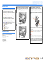 4
4
-
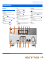 5
5
-
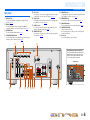 6
6
-
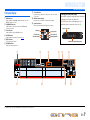 7
7
-
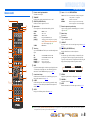 8
8
-
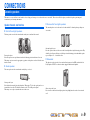 9
9
-
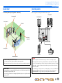 10
10
-
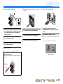 11
11
-
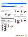 12
12
-
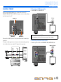 13
13
-
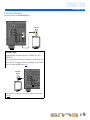 14
14
-
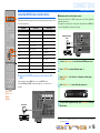 15
15
-
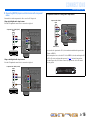 16
16
-
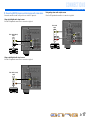 17
17
-
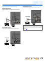 18
18
-
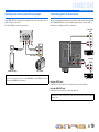 19
19
-
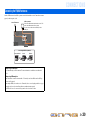 20
20
-
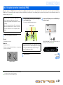 21
21
-
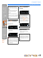 22
22
-
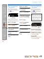 23
23
-
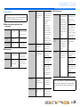 24
24
-
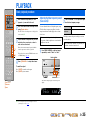 25
25
-
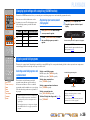 26
26
-
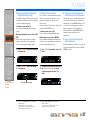 27
27
-
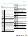 28
28
-
 29
29
-
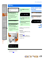 30
30
-
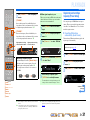 31
31
-
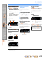 32
32
-
 33
33
-
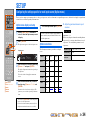 34
34
-
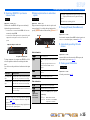 35
35
-
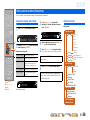 36
36
-
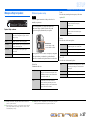 37
37
-
 38
38
-
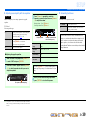 39
39
-
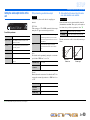 40
40
-
 41
41
-
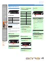 42
42
-
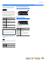 43
43
-
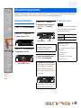 44
44
-
 45
45
-
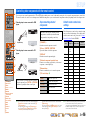 46
46
-
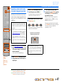 47
47
-
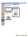 48
48
-
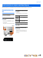 49
49
-
 50
50
-
 51
51
-
 52
52
-
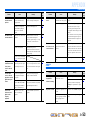 53
53
-
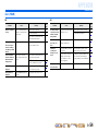 54
54
-
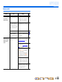 55
55
-
 56
56
-
 57
57
-
 58
58
-
 59
59
-
 60
60
-
 61
61


Yamaha HTR-3063 El manual del propietario
- Categoría
- Receptor
- Tipo
- El manual del propietario
en otros idiomas
- English: Yamaha HTR-3063 Owner's manual
Artículos relacionados
-
Yamaha HTR-2064 El manual del propietario
-
Yamaha HTR-4063 El manual del propietario
-
Yamaha HTR-5063 El manual del propietario
-
-
-
Yamaha RX-V467 El manual del propietario
-
Yamaha RX-V567 El manual del propietario
-
Yamaha RX-V767 El manual del propietario
-
-
Yamaha RX-V1067 El manual del propietario