Dell Supported Configurations for Oracle Database 10g R2 for Windows Guía del usuario
- Tipo
- Guía del usuario

Dell PowerEdge Systems
Oracle Database on Microsoft
Windows Server x64
Storage and Network
Guide
Version 4.4

Notes, Cautions, and Warnings
NOTE: A NOTE indicates important information that helps you make better use of
your computer.
CAUTION: A CAUTION indicates potential damage to hardware or loss of data if
instructions are not followed.
WARNING: A WARNING indicates a potential for property damage, personal
____________________
Information in this publication is subject to change without notice.
© 2009–2010 Dell Inc. All rights reserved.
Reproduction of these materials in any manner whatsoever without the written permission of Dell Inc.
is strictly forbidden.
Trademarks used in this text: Dell™, the DELL logo, EqualLogic™, PowerEdge™, and PowerVault™
are trademarks of Dell Inc.; EMC
®
and PowerPath
®
are registered trademarks of EMC Corporation;
Intel
®
is a registered trademark of Intel Corporation in the U.S. and other countries; Microsoft
®
,
Windows
®
and Windows Server
®
are either trademarks or registered trademarks of Microsoft
Corporation in the US and/or other countries; Oracle
®
is a registered trademark of Oracle Corporation
in the US and/or other countries.
Other trademarks and trade names may be used in this publication to refer to either the entities claiming
the marks and names or their products. Dell Inc. disclaims any proprietary interest in trademarks and
trade names other than its own.
July 2010 Rev. A03

Contents 3
Contents
1 Overview . . . . . . . . . . . . . . . . . . . . . . . . . . 7
Required Documentation for Deploying the
Dell Oracle Database
. . . . . . . . . . . . . . . . . . . 7
Terminology Used in This Document
. . . . . . . . . . . 8
Getting Help
. . . . . . . . . . . . . . . . . . . . . . . . 9
Dell Support. . . . . . . . . . . . . . . . . . . . . . 9
Oracle Support . . . . . . . . . . . . . . . . . . . . 9
2 Fibre Channel Cluster Setup . . . . . . . . . . 11
Cabling Your Dell/EMC Fibre Channel Storage . . . . . 13
3 SAS Cluster Setup for the
Dell PowerVault MD3000 . . . . . . . . . . . . 15
Cabling Your SAS Storage System. . . . . . . . . . . . 17
4 iSCSI Cluster Setup for the Dell
PowerVault MD3000i and PowerVault
MD1000 Expansion Enclosures . . . . . . . . 19
Setting Up iSCSI Cluster With Dell PowerVault
MD3000i Storage System and Dell PowerVault
MD1000 Expansion Enclosures
. . . . . . . . . . . . . 21
Cabling Your iSCSI Storage System . . . . . . . . 21

4 Contents
5 iSCSI Cluster Setup for the
Dell EqualLogic PS Series
Storage Systems . . . . . . . . . . . . . . . . . . . 25
Cabling Dell EqualLogic iSCSI Storage System . . . . . 25
6 Configuring Network and Storage
for Oracle RAC Database . . . . . . . . . . . . 29
Configuring the Public and Private Networks. . . . . . 29
Configuring and Teaming the Private Network . . . 30
Configuring NIC Teaming for Your Private
Network Adapters . . . . . . . . . . . . . . . . . 31
Configuring the IP Addresses for Your
Public and Private Network Adapters . . . . . . . 33
Installing the Host-Based Software
Required for Storage
. . . . . . . . . . . . . . . . . . . 36
Installing Multi-Path Software for Storage
. . . . . . . 36
Installing EMC PowerPath for
Dell/EMC Systems. . . . . . . . . . . . . . . . . . 36
Installing Multi-Path Driver Software for
PowerVault MD3000 or PowerVault MD3000i . . . 37
Installing Multi-Path Driver Software for
EqualLogic iSCSI Storage Array . . . . . . . . . . 37
Verifying Multi-Path Driver Functionality . . . . . . 37
Verifying and Upgrading the Firmware . . . . . . . . . 37
Configuring Your EqualLogic iSCSI Storage
. . . . . . . 38
Creating Volumes . . . . . . . . . . . . . . . . . . 38
Configuring iSCSI Networks . . . . . . . . . . . . 39
Configuring Host Access to Volumes . . . . . . . . 39
Configuring Microsoft iSCSI Initiator . . . . . . . . 40

Contents 5
Verifying the Storage Assignment to the Nodes . . . . 41
Preparing the Disks for Oracle Clusterware,
Database, and Backup
. . . . . . . . . . . . . . . . . . 42
Enabling the Automount Option for
the Shared Disks . . . . . . . . . . . . . . . . . . 43
Preparing the OCR and Voting Disks for
Clusterware on Windows Server 2003 . . . . . . . 43
Preparing the OCR and Votingdisk for
Clusterware on Windows Server 2008 . . . . . . . 45
Preparing the Database Disk and
Flash Recovery Area for Database
Storage With OCFS . . . . . . . . . . . . . . . . . 46
Preparing the Database Disk and
Flash Recovery Area for Database
Storage With ASM . . . . . . . . . . . . . . . . . 47
7 Index . . . . . . . . . . . . . . . . . . . . . . . . . . . . 49

6 Contents

Overview 7
Overview
The Storage and Networking Guide for Oracle Database on
Microsoft Windows applies to:
• Oracle Database 10g R2 Enterprise Edition on Microsoft Windows Server
2003 R2 Standard or Enterprise x64 Edition or Windows Server 2008 SP2
Enterprise or Standard x64 Edition.
• Oracle Database 10g R2 Standard Edition on Windows Server 2003 R2
SP2 Standard x64 Edition or Windows Server 2008 SP2 Standard
x64
Edition.
Required Documentation for Deploying the
Dell
Oracle Database
The documents required for installing the Dell|Oracle database are:
•
Oracle Database on Microsoft Windows Server x64 Operating System and
Hardware Installation Guide
—Describes the required minimum hardware
and software versions, how to install and configure the operating system,
how to verify the hardware and software configurations, and how to obtain
open source files.
•
Oracle Database on Microsoft Windows Server x64 Storage and Network
Guide
—Describes how to install and configure the network and the
storage solutions.
•
Oracle Database on Microsoft Windows Server x64 Database Setup and
Installation Guide
—Describes how to install and configure the
Oracle
database.
•
Oracle Database on Microsoft Windows Server x64 Troubleshooting
Guide
—Describes how to troubleshoot and resolve errors encountered
during the installation procedures described in the previous
modules.
NOTE: All modules provide information on how to receive technical assistance
from Dell.

8 Overview
Terminology Used in This Document
This document uses the terms logical unit number (LUN) and virtual disk.
These terms are synonymous and can be used interchangeably. The term
LUN is commonly used in a Dell/EMC Fibre Channel storage system
environment and virtual disk is commonly used in a Dell PowerVault SAS
or iSCSI (Dell PowerVault MD3000 and Dell PowerVault MD3000i with
Dell PowerVault MD1000 expansion) storage environment.
Dell EqualLogic PS series storage arrays include storage virtualization
technology. To better understand how these arrays operate, it is helpful to be
familiar with some of the terminologies used to describe these arrays and
their functions:
•
Member
—A single PS series array.
•
Group
—A set of one or more members that can be centrally managed.
Host servers access the data through a single group IP address.
•
Pool
—A RAID that can consist of the disks from one or more members.
•
Volume
—A LUN or virtual disk that represents a subset of the capacity of
a pool.

Overview 9
Getting Help
This section provides information on contacting Dell or Oracle for
whitepapers, supported configurations, training, technical support,
and general information.
Dell Support
• For detailed information about using your system, see the documentation
that came with your system components.
• For whitepapers, Dell-supported configurations, and general information,
see
dell.com/oracle
.
• For Dell technical support for your hardware and operating system
software and to download the latest updates for your system, see
support.dell.com
. Information about contacting Dell is provided in the
Dell PowerEdge Systems Oracle Database on Microsoft Windows Server x64
Operating System and Hardware Installation Guide
and
Dell PowerEdge
Systems Oracle Database on Microsoft Windows Server x64 Troubleshooting
Guide
of your system.
• Dell Enterprise Training and Certification is now available;
see
dell.com/training
for more information. This training service may
not
be offered in all locations.
Oracle Support
• For training information on your Oracle software and application
clusterware, and for information about contacting Oracle, see
oracle.com
or see your Oracle documentation.
• Technical support, downloads, and other technical information is available
at
metalink.oracle.com
.


Fibre Channel Cluster Setup 11
Fibre Channel Cluster Setup
WARNING: Before you begin any of the procedures in this section, read the
safety information that shipped with your system. For additional best practices
information, see dell.com/regulatory_compliance.
After a Dell Managed Services representative completes the setup of your
Fibre Channel cluster, verify the hardware connections and the hardware and
software configurations as described in this section. Figure 2-1 and Figure 2-2
show an overview of the connections required for the cluster and Table 2-1
summarizes the cluster connections.
Figure 2-1. Hardware Connections for a SAN-Attached Fibre Channel Cluster
Client Systems
Gigabit Ethernet Switches (Private Network)
Dell PowerEdge Systems
(Oracle Database)
CAT 5e/6 (Public NIC)
CAT 5e/6 (Copper Gigabit NIC)
Fiber Optic Cables
Dell/EMC Fibre Channel
Storage Systems
Dell/EMC Fibre Channel
Switches (SAN)
LAN/W AN
Additional Fiber Optic Cables

12 Fibre Channel Cluster Setup
Table 2-1. Fibre Channel Hardware Interconnections
Cluster Component Connections
Dell PowerEdge
system node
• One Category 5 enhanced (CAT 5e) or CAT 6 cable from the
public NIC to
the LAN
• One CAT 5e or CAT 6 cable from the private Gigabit NIC to
the Gigabit Ethernet switch
• One CAT 5e or CAT 6 cable from a redundant private
Gigabit
NIC to a redundant Gigabit Ethernet switch
• One fiber optic cable from HBA 0 to Fibre Channel switch 0
• One fiber optic cable from HBA 1 to Fibre Channel switch 1
Dell/EMC Fibre
Channel storage
system
• Two CAT 5e or CAT 6 cables connected to the LAN
• One to four fiber optic cable connections to each Fibre
Channel switch. For
example, for a four-port configuration:
–One
fiber optic cable
from SPA port 0 to Fibre Channel
switch 0
–One
fiber optic cable
from SPA port 1 to Fibre Channel
switch 1
–One
fiber optic cable
from SPB port 0 to Fibre Channel
switch 1
•One
fiber optic cable
from SPB port 1 to Fibre Channel switch 0
Dell/EMC Fibre
Channel switch
• One to four fiber optic cable connections to the
Dell/EMC
Fibre Channel storage system
• One fiber optic cable connection to each PowerEdge
system
HBA
Gigabit Ethernet
switch
• One CAT 5e or CAT 6 connection to the private Gigabit NIC
on each PowerEdge system
• One CAT 5e or CAT 6 connection to the remaining Gigabit
Ethernet switch

Fibre Channel Cluster Setup 13
Cabling Your Dell/EMC Fibre Channel Storage
You can configure your Oracle cluster storage system in a four-port storage
area network (SAN) attached configuration, depending on your needs.
See the following procedures for both configurations.
Figure 2-2 illustrates the hardware connections used in setting up a
SAN-attached Fibre Channel cluster.
Figure 2-2. Cabling in a Dell/EMC SAN-Attached Fibre Channer Cluster
Two HBA Ports for Node 1
Two HBA Ports for Node 2
sw1
Dell/EMC CX4-480 Fibre Channel Storage
sw0
SP-B
SP-A

14 Fibre Channel Cluster Setup
To configure your Oracle cluster storage system in a four-port, SAN-attached
configuration (see Figure 2-2):
1
Connect one optical cable from SP-A port 0 to Fibre Channel switch 0.
2
Connect one optical cable from SP-A port 1 to Fibre Channel switch 1.
3
Connect one optical cable from SP-B port 0 to Fibre Channel switch 1.
4
Connect one optical cable from SP-B port 1 to Fibre Channel switch 0.
5
Connect one optical cable from HBA 0 on node 1 to
Fibre
Channel switch 0.
6
Connect one optical cable from HBA 1 on node 1 to
Fibre
Channel switch 1.
7
Connect one optical cable from HBA 0 of each additional node to
Fibre
Channel switch 0.
8
Connect one optical cable from HBA 1 of each additional node to
Fibre
Channel switch 1.

SAS Cluster Setup for the Dell PowerVault MD3000 15
SAS Cluster Setup for the
Dell
PowerVault MD3000
WARNING: Before you begin any of the procedures in this section, read the
safety information that shipped with your system. For additional best practices
information, see dell.com/regulatory_compliance.
This section provides information and procedures to configure your
Dell PowerEdge systems and PowerVault MD3000 hardware and software
to function in an Oracle Real Application Cluster (RAC) environment.
Verify the hardware connections, and the hardware and software
configurations as described in this section using Figure 3-1, Table 3-1,
and Table 3-2.
Figure 3-1. Cabling the Serial-Attached SCSI (SAS) Cluster and
Dell
PowerVault MD3000
Public Network
LAN/WAN
PowerEdge Systems
PowerVault MD3000
Storage System
CAT 5e/6 (Copper Gigabit NIC)
CAT 5e/6 (Copper Gigabit NIC)
SAS Cables

16 SAS Cluster Setup for the Dell PowerVault MD3000
Table 3-1. SAS Cluster Hardware Interconnections
Cluster Component Connections
PowerEdge system node
• One CAT 5e/6 cable from public NIC to the local
area network (LAN).
• One CAT 5e/6 cable from private Gigabit NIC to
Gigabit Ethernet switch (private network).
• One CAT 5e/6 cable from redundant private Gigabit
NIC to redundant Gigabit Ethernet switch
(private
network).
• Two SAS connections to a PowerVault MD3000
storage system node using a SAS 5/E. See
“Cabling
Your SAS Storage System” on page 17.
PowerVault MD3000
• Two CAT 5e/6 cables connected to a LAN (one from
each storage processor module).
• Two SAS connections to each PowerEdge system
node using a SAS 5/E controller. See
“Cabling Your
SAS Storage System” on page 17.
Gigabit Ethernet switch
• One CAT 5e/6 connection to the private Gigabit
NIC on each PowerEdge system.
• One CAT 5e/6 connection to the other Gigabit
Ethernet switch.

SAS Cluster Setup for the Dell PowerVault MD3000 17
Cabling Your SAS Storage System
SAS clusters can only be installed in a direct-attached cluster and are limited
to two nodes only.
To configure your nodes in a direct-attached configuration (see Figure 3-2):
1
Connect one SAS cable from a port of the SAS controller of node 1 to the
In-0 port of RAID controller 0 in the PowerVault MD3000 RAID enclosure.
2
Connect one SAS cable from a port of the other SAS controller of node 1
to the In-0 port of RAID controller 1 in the PowerVault MD3000 RAID
enclosure.
3
Connect one SAS cable from a port of the SAS controller of node 2 to the
In-1 port of RAID controller 0 in the PowerVault MD3000 RAID enclosure.
4
Connect one SAS cable from a port of the other SAS controller of node 2
to the In-1 port of RAID controller 1 in the PowerVault MD3000 RAID
enclosure.
Figure 3-2. Cabling in a Direct-Attached SAS Cluster
Dual-HBA Host Server
Dual-HBA Host Server
RAID Controller Module 1
PowerVault MD3000 RAID
Enclosure
MD1000 Expansion Enclosure
MD1000 Expansion Enclosure
RAID Controller Module 0


iSCSI Cluster Setup 19
iSCSI Cluster Setup for the
Dell
PowerVault MD3000i
and
PowerVault MD1000
Expansion
Enclosures
WARNING: Before you begin any of the procedures in this section, read the
safety information that shipped with your system. For additional best practices
information, see dell.com/regulatory_compliance.
This section provides information and procedures to configure your
Dell PowerEdge systems and Dell PowerVault MD3000i hardware
and software to function in an Oracle Real Application Cluster (RAC)
environment.
Verify the hardware connections, and the hardware and software
configurations, using the Supported Configuration figures contained in the
Dell PowerVault MD3000i Support Matrix available at support.dell.com.
Table 4-1. iSCSI Hardware Interconnections
Cluster Component Connections
One PowerEdge
system
node
• One CAT 5e/6 cable from public NIC to the local area
network (LAN).
• One CAT 5e/6 cable from private Gigabit NIC to Gigabit
Ethernet switch (private network).
• One CAT 5e/6 cable from redundant private Gigabit NIC
to redundant Gigabit Ethernet switch (private network).
NOTE: For additional information on Dell PowerVault
MD3000i system see your Dell PowerVault MD3000i SetUp
documentation.

20 iSCSI Cluster Setup
One Dell PowerVault
MD3000i storage
system
• Two CAT 5e/6 cables connected to LAN (one from each
storage processor module) for the management interface.
• Two CAT 5e/6 cables per storage processor for iSCSI
interconnect.
NOTE: For additional information on Dell PowerVault
MD3000i system see your Dell PowerVault MD3000i Setup
documentation.
One Dell PowerVault
MD1000 storage
expansion enclosure
(optional)
Additional Serial-attached SCSI (SAS) cable connections
as required for the MD1000 expansion enclosures.
Table 4-1. iSCSI Hardware Interconnections
Cluster Component Connections

iSCSI Cluster Setup 21
Setting Up iSCSI Cluster With Dell PowerVault
MD3000i Storage System and Dell PowerVault
MD1000 Expansion Enclosures
Cabling Your iSCSI Storage System
Direct-attached iSCSI clusters are limited to two nodes only.
Figure 4-1. Cabling iSCSI Direct-Attached Clusters
To configure your nodes in a direct-attached configuration (see Figure 4-1):
1
Connect one CAT 5e/6 cable from a port (iSCSI HBA or NIC) of node 1
to
the In-0 port of RAID controller 0 in the
Dell PowerVault
MD3000i
storage
enclosure.
2
Connect one CAT 5e/6 cable from the other port (iSCSI HBA or NIC)
of
node 1 to the In-0 port of RAID controller 1 in the
Dell PowerVault
MD3000i storage enclosure.
3
Connect one CAT 5e/6 cable from a port (iSCSI HBA or NIC) of node 2
to
the In-1 port of RAID controller 0 in the
Dell PowerVault
MD3000i
storage
enclosure.
Two-Node Cluster
Ethernet Management
Port (2)
Corporate, Public or
Private Network
Standalone (One or
Two) Host Servers
PowerVault MD3000i RAID
Enclosure (Dual Controller)
CAT 5e/6 (Gigabit NIC for Management)
CAT 5e/6(Gigabit NIC iSCSI Ports)

22 iSCSI Cluster Setup
4
Connect one CAT 5e/6 cable from the other port (iSCSI HBA or NIC)
of
node 2 to the In-1 port of RAID controller 1 in the
Dell PowerVault
MD3000i storage enclosure.
5
Connect two SAS cables from the two MD3000 out ports to the two
In
ports of the first Dell PowerVault
MD1000 expansion
enclosure
(Optional).
6
Connect two SAS cables from the two MD1000 out ports to the In-0 ports
of the second
Dell PowerVault
MD1000 expansion enclosure (Optional).
NOTE: For information on configuring the PowerVault MD1000 expansion
enclosure, see the Dell PowerVault MD3000 Storage System documentation
available at support.dell.com/manuals.
Switched iSCSI clusters can support up to eight nodes.
Figure 4-2. Cabling iSCSI Switched Clusters
CAT 5e/6 (Gigabit NIC for Management)
CAT 5e/6 (Gigabit NIC iSCSI Ports)
Up to 16 Standalone Host
Servers
IP SAN (Dual Gigabit
Ethernet Switches)
Ethernet Management Port (2)
PowerVault MD3000i RAID
Enclosure (Dual Controller)
Corporate, Public or
Private Network

iSCSI Cluster Setup 23
To configure your nodes in a switched configuration (see Figure 4-2):
1
Connect one CAT 5e/6 cable from a port (iSCSI HBA or NIC) of node 1 to
the port of network switch 1.
2
Connect one CAT 5e/6 cable from a port (iSCSI HBA or NIC) of node 1 to
the port of network switch 2.
3
Connect one CAT 5e/6 cable from a port (iSCSI HBA or NIC) of node 2 to
the port of network switch 1.
4
Connect one CAT 5e/6 cable from a port (iSCSI HBA or NIC) of node 2 to
the port of network switch 2.
5
Connect one CAT 5e/6 cable from a port of switch 1 to the In-0 port of
RAID controller 0 in the
Dell PowerVault
MD3000i storage enclosure.
6
Connect one CAT 5e/6 cable from the other port of switch 1 to the
In-0
port of RAID controller 1 in the
Dell PowerVault
MD3000i
storage
enclosure.
7
Connect one CAT 5e/6 cable from a port of switch 2 to the In-1 port of
RAID controller 0 in the
Dell PowerVault
MD3000i storage enclosure.
8
Connect one CAT 5e/6 cable from the other port of switch 2 to the
In-1 port of RAID controller 1 in the
Dell PowerVault
MD3000i
storage enclosure.
9
Connect two SAS cables from the two MD3000i out ports to the two
In
ports of the first
Dell PowerVault
MD1000 expansion enclosure
(Optional).
10
Connect two SAS cables from the two MD1000 out ports to the In-0 ports
of the second
Dell PowerVault
MD1000 expansion enclosure (Optional).
NOTE: For information on configuring the Dell PowerVault MD1000 expansion
enclosure, see the Dell PowerVault MD3000 Storage System documentation
available at support.dell.com/manuals.
NOTE:
See the Solutions Deliverable List (SDL) found at
dell.com/oracle
and select
the appropriate solution. After selecting the solution, verify that the firmware version
for your storage is at or above the required firmware version found in the SDL
.

24 iSCSI Cluster Setup

iSCSI Cluster Setup for the Dell EqualLogic PS Series Storage Systems 25
iSCSI Cluster Setup for the
Dell
EqualLogic PS Series
Storage
Systems
WARNING: Before you begin any of the procedures in this section, read the
safety information that shipped with your system. For additional best practices
information, see dell.com/regulatory_compliance.
Cabling Dell EqualLogic iSCSI Storage System
Host servers can be attached to the Dell EqualLogic iSCSI array through an
IP storage area network (SAN) industry-standard Gigabit Ethernet switch.
Figure 5-1 shows the recommended network configuration for a dual control
module PS5000XV array. This configuration includes two Dell PowerConnect
54xx Gigabit Ethernet switches, to provide highest network availability and
maximum network bandwidth.
It is recommended that you use two Gigabit Ethernet switches because in
the event of a switch failure in a single ethernet switch environment, all
hosts lose access to the storage until the switch is physically replaced and
the configuration restored. For such configurations there should be multiple
ports with link aggregation providing the inter-switch, or trunk connection.
Additionally, it is recommended that one Gigabit interface connects to one
Ethernet switch from each of the control modules, and the other two Gigabit
interfaces connect to the other Ethernet switch.

26 iSCSI Cluster Setup for the Dell EqualLogic PS Series Storage Systems
Figure 5-1. Recommended Network Configuration
Figure 5-2 is an architecture overview of a sample Oracle RAC configuration
with three PS5000XV arrays.
Table 5-1 describes the cable colors and their significance. The PS5000XV
storage arrays provide the physical storage capacity for the Oracle
RAC database.
Table 5-1. Cable Color Legend
Cable Color Denotes
Blue
iSCSI storage area network (SAN)
Brown Oracle RAC private interconnect network
Black public network
Trunk Links
Dell PowerConnect 54xx
Gigabit Ethernet Switches for
iSCSI Storage Area Network
Operations Panel
Rear View of Dell EqualLogic iSCSI
Storage Array
Power Supply and
Cooling Module 1
iSCSI Storage Area Network
Control Module 1 Control Module 0 Power Supply and
Cooling Module 0

iSCSI Cluster Setup for the Dell EqualLogic PS Series Storage Systems 27
Figure 5-2. Sample Oracle RAC Configuration With Three PS5000XV Arrays
LAN/WAN
2 GB Link
Aggregation Group
Dell PowerConnect 5324
Gigabit Ethernet Switch
Dell PowerConnect 5324
Gigabit Ethernet Switch
Dell PowerEdge
2950 III Servers
Dell PowerConnect 5424/5448
Gigabit Ethernet Switches
Dell EqualLogic
PS5000XV iSCSI
Storage Arrays
Storage Member
oracle-member03
FRA Volume
Storage Pool RAID-5
Storage Member
oracle-member02
Storage Member
oracle-member01
OCR and Voting Disk
Volume
Data Volume
Storage Pool RAID 10
Storage Group: oracle-group
8 Gb Aggregation
Group
Public Network
Oracle RAC Private Network
iSCSI Storage Area Network

28 iSCSI Cluster Setup for the Dell EqualLogic PS Series Storage Systems
As illustrated in Figure 5-2, the group named oracle-group includes three
PS5000XV members:
• oracle-member01
• oracle-member02
• oraclemember03
When a member is initialized, it can be configured with RAID 10, RAID 5,
or RAID 50. For more information on how to initialize an EqualLogic array,
see the Dell EqualLogic User’s Guide.
A PS Series storage group can be segregated into multiple tiers or pools.
Tiered storage provides administrators with greater control over how disk
resources are allocated. At any one time, a member can be assigned to only
one pool. It is easy to assign a member to a pool and also to move a member
between pools with no impact to data availability. Pools can be organized
according to different criteria, such as disk types or speeds, RAID levels, and
application types.
In Figure 5-2 pools are organized by member RAID levels:
• One pool with the name RAID-10 consists of RAID 10 members.
• One pool with the name RAID-5 consists of RAID 5 members.

Configuring Network and Storage for Oracle RAC Database 29
Configuring Network and Storage
for Oracle RAC Database
This section provides information about:
• Configuring the public and private networks.
• Verifying the storage configuration.
• Configuring the shared storage for Oracle Clusterware and the
Oracle
Database.
NOTE: Oracle RAC requires an ordered list of procedures. To configure networking
and storage in a minimal amount of time, perform the procedures listed in this
chapter in order.
Configuring the Public and Private Networks
NOTE: Each node requires a unique public and private internet protocol (IP)
address and an additional public IP address to serve as the virtual IP address for
the client connections and connection failover. The virtual IP address must belong
to the same subnet as the public IP address. All public IP addresses, including the
virtual IP address should be registered with the domain naming service (DNS). If a
DNS server is not available, IP addresses have to be registered in the hosts file on
all cluster nodes.
Depending on the number of NIC ports available, configure the public and
private interfaces as shown in Table 6-1.
Table 6-1. NIC Port Assignments
NIC Port Three Ports Available Four Ports Available
1 Public IP and virtual IP Public IP
2 Private IP (NIC team) Private IP (NIC team)
3 Private IP (NIC team) Private IP (NIC team)
4 NA Virtual IP

30 Configuring Network and Storage for Oracle RAC Database
Configuring and Teaming the Private Network
Before you deploy the cluster, assign a private IP address and host name to
each cluster node. This procedure ensures that the nodes can communicate
with each other through the private interface.
Table 6-2 provides an example of a network configuration for a two-node
cluster.
NOTE: This example assumes all the IP addresses are registered in the hosts file of
all cluster nodes.
NOTE: The two bonded NIC ports for a private network should be on separate
PCI
buses. For example, a bonded pair can consist of one on-board NIC and one
add-on NIC card.
Table 6-2. Network Configuration Example for a Two-Node Cluster
Host Name Type IP Address Registered In
rac1 Public 155.16.170.1 %SystemRoot%\system32\drivers\etc\hosts
rac2 Public 155.16.170.2 %SystemRoot%\system32\drivers\etc\hosts
rac1-vip Virtual 155.16.170.201 %SystemRoot%\system32\drivers\etc\hosts
rac2-vip Virtual 155.16.170.202 %SystemRoot%\system32\drivers\etc\hosts
rac1-priv Private 10.10.10.1 %SystemRoot%\system32\drivers\etc\hosts
rac2-priv Private 10.10.10.2 %SystemRoot%\system32\drivers\etc\hosts

Configuring Network and Storage for Oracle RAC Database 31
Configuring NIC Teaming for Your Private Network Adapters
NOTE: TCP Offload Engine (TOE) functionality of a TOE-capable NIC is not
supported in this solution.
To configure NIC teaming for your private network adapters:
1
On node 1, identify two network adapters that are used for NIC teaming.
2
Connect an ethernet cable from each selected network adapter to the
private network switch.
3
If node 1 is configured with Broadcom NICs, go to step 4. If node 1 is
configured with Intel NICs, configure NIC teaming by performing the
following steps:
a
Right-click
My Computer
and select
Manage
.
b
On the
Computer Management
window, select
Device Manager
.
c
Expand the
Network Adapters
tab.
d
Right-click the
Intel NIC
, which is identified for NIC teaming and
select
Properties
.
e
Click the
Teaming
tab.
f
Select
Team with other Adapters
and then select
New Team
.
g
Specify a name for NIC team and click
Next
.
h
On the
Select the adapters to include in this team
box, select the
remaining network adapters that you identified for NIC teaming and
click
Next
.
i
On the
Select a team mode list
box, select
Adaptive Load Balancing
.
j
Click
Finish
to complete the teaming.
k
On the
Team Properties
window, click
OK
.
l
On the Intel
NIC's Properties
window, click
OK
.
m
Close the
Computer Management
window.

32 Configuring Network and Storage for Oracle RAC Database
4
If node 1 is configured with Broadcom NICs, configure NIC teaming by
performing the following steps. If not go to
step 5.
a
Click
Start
→
Programs
→
Broadcom
→
Broadcom Advanced Control
Suite 3.
The
Broadcom Advanced Control Suite 3
window is displayed.
b
Highlight
Team Management
, and click
Teams
and select
Create a Team
.
The
Broadcom Teaming Wizard
window is displayed.
c
Click
Next
.
d
In the
Enter the name for the team
field, type
Private
and
click
Next
.
e
On the
Team Type
field, select
Smart Load Balancing (TM) and
Failover (SLB)
and click
Next
.
f
On the
Assigning Team Members
window, in the
Available Adapters
box, select the network adapters you identified for NIC teaming and
add them to the
Team Members
box.
NOTE: When configuring integrated Broadcom NICs into a team, the
following warning message is displayed on Dell PowerEdge 6850 systems.
Including this adapter in a team will disrupt the
system management features. Click Yes to proceed.
g
Click
Next
.
h
On the
Designating a Standby Member
window, either select a NIC
or select
Do not configure a standby member
.
i
On the
Configuring Live Link
window, select
No
and click
Next
.
j
On the
VLAN Support
window, if there is a VLAN you require to
configure, select
Add VLAN
. If not, select
Skip manage VLAN
.
k
Click
Preview
to verify the NIC team and the adapters. After
verification, select
Commit changes to system
and exit the wizard.
Click
Finish
.
l
On the
Information Message
window, click
Yes
to proceed.
m
On the
Broadcom Advanced Control Suite 3
window, click
File
then
Exit
.
5
Repeat step 1 to step 4 on the remaining nodes.

Configuring Network and Storage for Oracle RAC Database 33
Configuring the IP Addresses for Your Public and Private
Network
Adapters
NOTE: The TOE functionality of TOE-capable NIC is not supported in this solution.
To configure the IP addresses for your public and private network adapters:
1
Update the adapter’s network interface name, if required. Otherwise, go to
step 3.
a
On node 1, click
Start
and navigate to
Settings
→
Control Panel
→
Network Connections
.
b
On the
Network Connections
window, right-click the public network
adapter you want to rename, and select
Rename
.
NOTE: When you configure your network adapters on the cluster nodes, use
identical names for the public adapters and the private adapters on all cluster
nodes. Otherwise, the Oracle database installer generates an error and
prevents you from completing the installation procedure.
c
Rename the public adapter name to
Public
and press <Enter>.
d
Right-click the Private NIC team you want to rename and select
Rename
.
e
Rename the Private NIC team to
Private
and press <Enter>.
2
Configure the IP addresses.
NOTE: You must set a default gateway for your public interface, otherwise,
the Clusterware installation may fail.
a
Click
Start
→
Settings
→
Control Panel
→
Network Connections
→
Public
→
Properties
.
b
Double-click
Internet Protocol (TCP/IP)
.
c
Click
Use the following IP address
, enter the required IP address,
default gateway address and the DNS server IP address, and click
OK
.
d
In the
Public Properties
window, select
Show icon in notification area
when connected
.
The network adapter status appears in the system tray after you
perform the procedures in this section.
e
Click
OK
.

34 Configuring Network and Storage for Oracle RAC Database
f
On the
Properties
window, click
Close
.
g
Repeat step a through step f on the Private NIC team.
NOTE: Private NIC team does not require a default gateway address and DNS
server entry.
3
Ensure that the public and private network adapters appear in the
appropriate order for access by network services.
a
On the Windows desktop, click
Start
→
Settings
→
Control Panel
→
Network Connections
.
b
On the
Network Connections
window, click
Advanced
and select
Advanced Settings
.
c
Select the
Adapter and Bindings
tab.
d
Ensure that the network adapters are listed in the following order:
i. Public
ii. Private
iii. <Any other network adapter>
NOTE: Click the up-and down-arrow keys to change the adapter order.
e
Click
OK
.
f
Close the
Network Connections
window.
4
On all nodes, add the public, private, and virtual IP addresses and host
name to the
%SystemRoot%\system32\drivers\etc\hosts
file.
NOTE: Add the public and virtual IP addresses to the hosts file only if they are
not registered with the DNS server.
For example, the following entries use the adapter IP and host name as
shown in
Ta b le 6-3.

Configuring Network and Storage for Oracle RAC Database 35
Table 6-3. IP Address and Node Names
NOTE: Registering the private IP addresses with the DNS server is not required
because the private network IP addresses are not accessible from the public
network.
5
Repeat step 1 to step 4 on the remaining nodes.
6
Ensure that the cluster nodes can communicate with the public and
private networks.
a
On node 1, open a command prompt window.
b
At the command prompt, type:
ping <public_host_name>
ping <private_host_name>
where <
public_host_name
> and <
private_host_name
> are
the host names for the public and private network adapters in the
remaining node.
If the node’s network adapters do not respond to ping commands, check
your network configuration and then repeat this step.
NOTE: Virtual internet protocol (VIP) is configured later and cannot be pinged
at this point.
c
Repeat step a through step b on the remaining nodes.
IP Address Node Name
155.16.170.1 rac1
155.16.170.2 rac2
10.10.10.1 rac1-priv
10.10.10.2 rac2-priv
155.16.170.201 rac1-vip
155.16.170.202 rac2-vip

36 Configuring Network and Storage for Oracle RAC Database
Installing the Host-Based Software Required
for
Storage
If you are installing Dell/EMC Fibre Channel Storage, see the Dell/EMC
documentation that came with your system to install the EMC Naviagent
software.
If you are installing a Dell PowerVault storage, see the Dell PowerVault
documentation that came with your system to install the Modular Disk
Storage Manager (MDSM) software from the Dell PowerVault Resource
media.
NOTE: The Microsoft iSCSI Software Initiator is required for a Dell PowerVault
MD3000i storage system. The Microsoft iSCSI Software Initiator can be
downloaded from microsoft.com.
Installing Multi-Path Software for Storage
Follow the documentation accompanying the storage device to install the
appropriate multi-path software.
Installing EMC PowerPath for Dell/EMC Systems
To install EMC PowerPath for Dell/EMC Systems:
1
On node 1, install EMC PowerPath.
NOTE: For more information, see the EMC PowerPath documentation that
came with your Dell/EMC storage system.
2
On completion of the installation procedure, restart your system.
3
Repeat step 1 and step 2 on the remaining nodes.

Configuring Network and Storage for Oracle RAC Database 37
Installing Multi-Path Driver Software for PowerVault MD3000 or
PowerVault MD3000i
In the case of a SAS or iSCSI (PowerVault MD3000 or PowerVault MD3000i
storage system) cluster, the Multi-Path software should already be installed
on your hosts as instructed in the section "Installing the Host-Based
Software Required for Storage" on page 36.
Installing Multi-Path Driver Software for EqualLogic iSCSI Storage Array
For more information see "Installing and Configuring Dell EqualLogic Host
Integration Tool (HIT) Kit" on page 39.
Verifying Multi-Path Driver Functionality
To verify the multi-path driver functionality:
1
Right-click
My Computer
and select
Manage
.
2
Expand
Storage
and click
Disk Management
.
One disk is displayed for each LUN assigned in the storage.
3
Ensure that each LUN is configured as a
Basic
disk.
4
Repeat step 1 to step 3 on the remaining nodes.
Verifying and Upgrading the Firmware
• Discover the host server’s direct-attached storage using the MDSM
software that is installed on the host server.
• Verify that the firmware for the following storage components is at the
minimum required version. Refer to the Solutions Deliverable List (SDL)
for the firmware version requirements.
• PowerVault MD3000i storage system firmware
• MD1000 expansion enclosure firmware

38 Configuring Network and Storage for Oracle RAC Database
Configuring Your EqualLogic iSCSI Storage
Creating Volumes
Before data can be stored, the PS5000XV physical disks must be configured
into usable components, known as volumes. A volume represents a portion of
the storage pool, with a specific size, access controls, and other attributes.
A volume can be spread across multiple disks and group members and is seen
on the network as an iSCSI target. Volumes are assigned to a pool and can be
easily moved between pools, with no impact on data availability. In addition,
automatic data placement and automatic load balancing occurs within a pool,
based on the overall workload of the storage hardware resources within
the pool.
NOTE: It is recommended that you keep the OCR mirror and the voting disk mirrors
on a different volume to avoid warning messages during OCR and voting disk
configuration.
Table 6-4. Volumes for Oracle RAC Configuration
Volume Minimum Size RAID Number of
Partitions
Used For Operating System
Mapping
First Area
Volume
3 GB 10 One extended
partition with
five logical
drives - 3 x
250
MB for
Voting Disk
and 2 x
300
MB for
OCR
Voting disk
and Oracle
Cluster
Registry
(OCR)
One extended
partition with five
logical drives:
3 x Voting Disk,
2 x OCR
Second Area
Volume(s)
Larger than
the size of
your database
10 One Data ASM disk group
DATABASEDG
Third Area
Volume(s)
Minimum
twice the size
of your
second area
volume(s)
5 One Flash
Recovery
Area
ASM disk group
FLASHBACKDG

Configuring Network and Storage for Oracle RAC Database 39
Table 6-4 shows a sample volume configuration. Create volumes in
PS5000XV array and create an access list to allow all host iSCSI network
interfaces to access the volumes.
Configuring iSCSI Networks
It is recommended that the host network interfaces for iSCSI traffic are
configured to use Flow Control and Jumbo frame for optimal performance.
To set Flow Control and Jumbo frame:
1
Select
Start
→
Settings
→
Network Connections
.
2
Highlight the iSCSI network interface, and right click
Properties
.
3
Click
Configure
.
4
Click
Advanced
.
5
Highlight
Jumbo Packet
, and set its value to 9014 bytes.
6
Highlight
Performance Options
, then click
Properties
.
The
Performance Options
window is displayed.
7
In the
Performance Options
window, highlight
Flow Control
, and set its
value to
Rx & Tx Enabled
.
8
Repeat step 2 to step 7 for all other network interfaces used for
iSCSI traffic.
Configuring Host Access to Volumes
Installing and Configuring Dell EqualLogic Host Integration Tool (HIT) Kit
To install and configure the Dell EqualLogic Host Integration Tool (HIT) kit:
1
Download the latest HIT tool kit on your database server.
2
Double-click
Setup64.exe
to launch the installation window.
3
In the
Welcome to the Host Integration Tools,
update program window,
click
Next
.
4
In the
License Agreements
window, select
I accept the terms of all the
license agreements
, and click
Next
.
5
On the
Installation Type
window, click
Next
.

40 Configuring Network and Storage for Oracle RAC Database
6
On the
Ready to install the components
window, click
Install
.
The
Installation Status
window and the
Software Update Installation
Wizard
window is displayed.
7
On the
Installation Complete
window, click
Finish
.
8
On the
System Restart Required
window, select Y
es, I want to restart my
computer now
, and click
OK
.
9
When the server restarts, a
Remote Setup Wizard
window is displayed.
10
Select
Configure MPIO
settings for this computer, then click
Next
.
11
Move the iSCSI network subnets under
Subnets included for MPIO
.
Move all other network subnets under
Subnets excluded from MPIO
.
Select Default load balancing policy (Least Queue Depth). Click
Finish
.
12
Repeat step 1 to step 11 on all other hosts in the cluster.
Configuring Microsoft iSCSI Initiator
To configure Microsoft iSCSI initiator:
1
Double-click the
Microsoft iSCSI Initiator
icon on desk top.
2
On the
iSCSI Initiator Properties
window
Discovery
tab, the IP address of
the EqualLogic group address should already be populated by the HIT tool
kit.
3
On the
iSCSI Initiator Properties
window
Targets
tab, click on one
volume that was created for the Oracle database. Click
Log On
.
4
On the
Log On to Target
window, check the two boxes by
Automatically restore this connection when the system boots, and
Enable
multi-path
.
5
Click
Advanced
.
6
On the
Advanced Settings
window
General
tab, perform the following
configurations:
a
Choose
Microsoft iSCSI Initiator by the Local adapter
drop-down
menu.
b
Choose an
iSCSI initiator IP address by the Source IP
drop-down
menu.
c
Choose
EqualLogic group IP address by the Target Portal
drop-down
menu.

Configuring Network and Storage for Oracle RAC Database 41
d
Select the
CHAP logon information
check box.
e
Enter the CHAP user name defined in EqualLogic storage, by the
User name
box.
f
Enter the CHAP password defined in EqualLogic storage, by the
Ta rg et
secret box.
g
Click
OK
.
7
On the
Log On to Target
window, click
OK
.
8
On the
iSCSI Initiator Properties
window
Ta rg et s
tab, the status of the
logged on volume should be Connected.
9
Repeat step 3 to step 8 to log on to the same volume for every other iSCSI
initiator IP addresses.
10
Repeat step 3 to step 9 to log on to all other volumes created for the
database.
11
Repeat step 1 to step 10 on all other hosts in the cluster.
Verifying the Storage Assignment to the Nodes
To verify the storage assignment to the nodes:
1
On the Windows desktop, right-click
My Computer
and select
Manage
.
2
On the
Computer Management
window, click
Device Manager
.
3
Expand
Disk drives
.
4
Under
Disk drives
, ensure that four small computer system interface
(SCSI) disk devices appear for each LUN or virtual disk assigned in the
storage.
5
Expand
Storage
and click
Disk Management
.
If the
Welcome to the Initialize and Convert Disk Wizard
is displayed,
perform
step a through step d. Otherwise, go to step 6.
a
On the
Welcome to the Initialize and Convert Disk Wizard
window,
click
Next
.
b
On the
Select Disks to Initialize
window, in the
Disks
window, select
the disks that are associated with your storage LUNs/virtual disks and
click
Next
.

42 Configuring Network and Storage for Oracle RAC Database
c
In the
Select Disks to Convert
window, clear the disk(s) that you
selected in
step b and click
Next
.
NOTE: This procedure ensures that your disks are configured as basic disks.
d
Click
Finish
.
6
On the
Disk Management
window, verify if four disks appear. The disks
should be similar in size to each other and to the LUNs/virtual disks that
are assigned to the nodes in the storage system.
7
Repeat step 1 to step 6 on the remaining nodes.
Preparing the Disks for Oracle Clusterware,
Database, and Backup
This section provides information on creating the logical drives for the
following disks:
•
Oracle Cluster Registry disk (OCR)
—Contains the cluster configuration
information
•
Voting disk
—Provides arbitration between the cluster nodes when the
private network or attached storage is unavailable to one or more nodes
•
Data and backup disks
—Provide storage areas for creating the database
(data disk) and saving the backup and log data (backup disk)
During the cluster configuration described in this document, you create
partitions on your shared storage. When you create the partitions, ensure that
the cluster nodes can detect the LUNs or logical disks that are created in the
attached storage system.
To prepare the disks for Oracle Clusterware, identify the OCR, voting, data,
and flash recovery area disks. After you identify the appropriate disks, perform
the following steps on node 1:
1
Enable the Automount option for the shared disks.
2
Prepare the OCR and voting disks for Clusterware on Windows Server 2003.
3
Prepare the OCR and voting disk for Clusterware on Windows Server 2008.
4
Prepare the database disk and flash recovery area for database storage with
OCFS.
5
Prepare the database disk and flash recovery area for database storage with
ASM.

Configuring Network and Storage for Oracle RAC Database 43
Enabling the Automount Option for the Shared Disks
To enable the Automount option for the shared disks:
1
On node 1, click
Start
and select
Run
.
2
In the
Run
field, type
cmd
and click
OK
.
3
At the command prompt, type
diskpart
and press <Enter>.
4
At the
DISKPART
command prompt, type
automount enable
and
press <
Enter
>.
The following message is displayed:
Automatic mounting of new volumes
enabled
.
5
At the
DISKPART
command prompt, type
exit
and press <
Enter
>.
6
Close the command prompt.
7
Repeat step 1 to step 6 on each of the remaining nodes.
Preparing the OCR and Voting Disks for Clusterware on
Windows
Server 2003
To prepare the OCR and voting disks for Clusterware on Windows Server 2003:
1
On the Windows desktop, right-click
My Computer
and select
Manage
.
2
Expand
Storage
and click
Disk Management
.
The storage disk that you initialized in the "Verifying Multi-Path Driver
Functionality" on page 37 is displayed as
Unallocated
.
3
Right-click the partition area of the first shared disks assigned to the
cluster nodes and select
New Partition.
The
Welcome to the
New Partition
wizard is displayed.
4
Click
Next
.
5
On the
Select Partition Type
window, select
Extended partition
and click
Next
.
6
On the
Specify Partition Size
window, accept the default partition size
and click
Next
.
7
Click
Finish
.
The disk partition area you selected in step 3 is configured as an extended
partition.

44 Configuring Network and Storage for Oracle RAC Database
8
Repeat step 3 to step 7 on all shared disks that are assigned to the cluster
nodes.
9
Create a logical drive for the OCR disk.
a
On the partition area of the disk identified for OCR and voting disk
(2
GB LUN/virtual disk), right-click the free space and select
New Logical Drive
.
The
Welcome to the New Partition
wizard is displayed.
b
Click
Next
.
c
On the
Select Partition Type
window, select
Logical drive
and
click
Next
.
d
On the
Specify Partition Size
window, type
120
in the
Partition size
in MB field
and click
Next
.
e
On the
Assign Drive Letter or Path
window, select
Do not assign a
drive letter or drive path
and click
Next
.
f
On the
Format Partition
window, select
Do not format this partition
and click
Next
.
g
Click
Finish
.
h
Repeat step a through step g to create an additional OCR disk.
10
Create a logical drive for the Voting Disk.
a
On the partition area of the disk identified for the OCR and voting
disk (2 GB LUN/virtual disk), right-click the free space and select
New Logical Drive
.
The
Welcome to the New Partition
wizard is displayed.
b
Click
Next
.
c
In the
Select Partition Type
window, select
Logical drive
and click
Next
.
d
In the
Specify Partition Size
window, in the
Partition
size in
MB
field,
type
50
and click
Next
.
e
In the
Assign Drive Letter or Path
window, select
Do not assign a
drive letter or drive path
and click
Next
.

Configuring Network and Storage for Oracle RAC Database 45
f
In the
Format Partition
window, select
Do not format this partition
and click
Next
.
g
Click
Finish
.
h
Repeat step a to step g to create two additional voting disk partitions.
NOTE: If you are using Redundant Voting Disk and OCR, repeat the steps outlined in
step 9 and step 10 for the redundant Voting Disk and OCR.
Preparing the OCR and Votingdisk for Clusterware on Windows Server
2008
NOTE: The steps to create extended partitions and to create logical drives are
identical to the steps of Windows Server 2003, however, it is no longer possible to
perform these steps in Windows Server 2008 from the Disk Management GUI.
To create extended partitions and logical drives:
1
Start
→
Run
and type
cmd
and click
Enter
to open a command prompt
window.
2
Ty p e
diskpart
in the command prompt to open the diskpart interface.
3
Enter
list disk
and a table is displayed as shown:
DISKPART> list disk
4
Enter
select disk [disk #]
of the target disk.
NOTE: The following steps explain how to create partitions and logical disks
for MBR disk.
5
Ty p e
create partition extended
and press
Enter
.
6
Ty p e
create partition logical size=
<size of volume in
megabytes> and press
Enter
.
Disk ### Status Size Free
Disk 0 Online 37 GB 0 MB
Disk 1 Online 2048 MB 2014 MB
Disk 2 Online 100 GB 100 GB
Disk 3 Online 200 GB 200 GB

46 Configuring Network and Storage for Oracle RAC Database
Preparing the Database Disk and Flash Recovery Area for Database
Storage With OCFS
NOTE: When using Automatic Storage Management (ASM), the ASM data disk
group should be larger than your database (multiple LUNs) and the ASM Flash
Recovery Area disk group should be at least twice the size of your data disk group.
NOTE: If you are creating the logical drives that are used to create the ASM
storage disk, ignore the following steps and see
"Preparing the Database Disk and
Flash Recovery Area for Database Storage With OCFS" on page 46.
To create logical drives that are used to create the Oracle’s Clustered File
System (OCFS) storage disk:
1
On node 1, create one logical drive for the Database.
a
Locate the disk that is assigned for the Oracle Database.
b
On the disk partition area, right-click the free space and select
New Logical Drive
.
The
Welcome to the New Partition
wizard is displayed.
c
Click
Next
.
d
In the
Select Partition Type
window, select
Logical drive
and click
Next
.
e
In the
Specify Partition Size
window in the
Partition
size in
MB
field,
type the appropriate size and click
Next
.
f
In the
Assign Drive Letter or Path
window, select
Do not assign a
drive letter or drive path
and click
Next
.
g
In the
Format Partition window
, select
Do not format this partition
and click
Next
.
h
Click
Finish
.
2
On node 1, create one logical drive for the Flash Recovery Area.
a
Locate the disk that is assigned for the Flash Recovery Area.
b
Perform step b to step h in step 1.
3
Restart all other nodes and login as administrator.

Configuring Network and Storage for Oracle RAC Database 47
Preparing the Database Disk and Flash Recovery Area for Database
Storage With ASM
NOTE: If you are creating the logical drives that are used to create the OCFS
storage disk, ignore the following steps and follow the procedures in
"Preparing the
Database Disk and Flash Recovery Area for Database Storage With OCFS" on
page 46.
To create logical drives that are used to create ASM disk storage:
1
Create one logical drive for the Database.
a
Locate the disk that is assigned for the Oracle database.
b
On the disk partition area, right-click the free space and
select
New
Logical Drive
.
The
Welcome to the New Partition
wizard is displayed.
c
Click
Next
.
d
In the
Select Partition Type
window, select
Logical drive
and click
Next
.
e
In the
Specify Partition Size
window, type the appropriate size in the
Partition size in MB field and click
Next
.
f
In the
Assign Drive Letter or Path
window, select
Do not assign a
drive letter or drive path
and click
Next
.
g
In the
Format Partition window
, select
Do not format this partition
and click
Next
.
h
Click
Finish
.
2
Create one logical drive for the Flash Recovery Area.
a
Locate the disk that is assigned for the Flash Recovery Area.
b
Perform step b to step h in step 1.
3
Restart all other nodes and log in as the administrator.

48 Configuring Network and Storage for Oracle RAC Database
Removing the Assigned Drive Letters
To remove the assigned drive letters:
1
On the Windows desktop for each node, right-click
My Computer
and
select
Manage
.
2
On the
Computer Management
window, expand
Storage and
click
Disk Management
.
3
If you find any drive letters assigned to the drives that you created in
"Preparing the OCR and Voting Disks for Clusterware on
Windows Server 2003" on page 43, perform the following steps:
a
Right-click the logical drive and select
Change Drive Letter and Paths
.
b
In the
Change Drive Letter and Paths
window, select the drive letter
and click
Remove
.
c
In the
Confirm window
, click
Yes
.
d
Repeat step a through step c for the remaining logical drives on the
storage partition.

Index 49
Index
A
ASM, 46
B
bonded pair, 30
C
cable
CAT 5e, 12
CAT 6, 12
SAS cable, 17
D
Dell/EMC Fibre Channel, 12
disks
Data and backup disks, 42
Oracle Cluster Registry disk, 42
Redundant Voting Disk, 45
Voting disk, 42
DNS, 29
E
EMC
PowerPath, 36
EqualLogic Terms
Group, 8
Member, 8
Pool, 8
Volume, 8
F
Flow Control, 39
G
Gigabit Ethernet switch, 12
H
Help
Dell Support, 9
Oracle Support, 9
I
IP address
public IP address, 29
virtual IP address, 29
iSCSI HBA, 21


Dell PowerEdge 系统
"Oracle Database on
Microsoft Windows Server x64"
(Microsoft Windows
Server x64 上的
Oracle Database
)
存储和网络指南
4.4 版

注、小心和警告
注:“注”表示可以帮助您更好地使用计算机的重要信息。
小心:
“小心”表示如果不遵循说明,就有可能损坏硬件或导致数据丢失。
警告:“警告”表示可能会造成财产损失、人身伤害甚至死亡。
____________________
本出版物中的信息如有更改,恕不另行通知。
©
2009
–
2010 Dell Inc.
版权所有,翻印必究。
未经
Dell Inc.
书面许可,严禁以任何形式复制这些材料。
本文中使用的商标:
Dell
™
、
DELL
徽标、
EqualLogic
™
、
PowerEdge
™
和
PowerVault
™
是
Dell
Inc.
的商标;
EMC
®
和
PowerPath
®
是
EMC Corporation
的注册商标;
Intel
®
是
Intel
Corporation
在美国和其它国家
/
地区的注册商标;
Microsoft
®
、
Windows
®
和
Windows
Server
®
是
Microsoft Corporation
在美国和
/
或其它国家
/
地区的商标或注册商标;
Oracle
®
是
Oracle Corporation
在美国和
/
或其它国家
/
地区的注册商标。
本出版物中述及的其它商标和产品名称是指拥有相应商标和产品名称的公司或其制造的产品。
Dell Inc.
对其它公司的商标和产品名称不拥有任何所有权。
2010
年
7
月
Rev. A03

目录 53
目录
1 概览 . . . . . . . . . . . . . . . . . . . . . . . . . . . . . 57
部署
Dell Oracle Database
所需的说明文件 . . . . . 57
本说明文件中使用的术语
. . . . . . . . . . . . . . . 58
获得帮助
. . . . . . . . . . . . . . . . . . . . . . . . . 59
Dell 支持 . . . . . . . . . . . . . . . . . . . . . . 59
Oracle 支持. . . . . . . . . . . . . . . . . . . . . 59
2 光纤信道群集设置 . . . . . . . . . . . . . . . . . 61
Dell/EMC
光纤信道存储布线
. . . . . . . . . . . . . . 63
3 Dell PowerVault MD3000 的 SAS
群集设置 . . . . . . . . . . . . . . . . . . . . . . . . . 65
SAS
存储系统布线
. . . . . . . . . . . . . . . . . . . 67
4 Dell PowerVault MD3000i 和
PowerVault MD1000 扩展盘柜的
iSCSI 群集设置 . . . . . . . . . . . . . . . . . . . . 69
安装带有
Dell PowerVault MD3000i
存储系统和
Dell PowerVault MD1000
扩展盘柜的
iSCSI
群集
. . . 70
iSCSI 存储系统布线 . . . . . . . . . . . . . . . . 70

54 目录
5 Dell EqualLogic PS Series
存储系统的 iSCSI 群集设置 . . . . . . . . . . 75
Dell EqualLogic iSCSI
存储系统的布线
. . . . . . . . 75
6 配置 Oracle RAC Database
的网络和存储 . . . . . . . . . . . . . . . . . . . . . 79
配置公用和专用网络 . . . . . . . . . . . . . . . . . . 79
配置并组队专用网络 . . . . . . . . . . . . . . . 80
为专用网络适配器配置 NIC 组队 . . . . . . . . 80
为公用网络适配器和专用网络
适配器配置 IP 地址 . . . . . . . . . . . . . . . . 83
安装存储所需的基于主机的软件 . . . . . . . . . . . 86
为存储安装多路径软件
. . . . . . . . . . . . . . . . . 86
为 Dell/EMC 系统安装 EMC PowerPath . . . . . . 86
为 PowerVault MD3000 或 PowerVault
MD3000i 安装多路径驱动程序软件 . . . . . . . 86
为 EqualLogic iSCSI 存储阵列安装多路
径驱动程序软件 . . . . . . . . . . . . . . . . . . 86
验证多路径驱动程序功能 . . . . . . . . . . . . 87
验证并升级固件. . . . . . . . . . . . . . . . . . . . . 87
配置
EqualLogic iSCSI
存储设备
. . . . . . . . . . . . 87
创建卷 . . . . . . . . . . . . . . . . . . . . . . . 87
配置 iSCSI 网络 . . . . . . . . . . . . . . . . . . 88
配置主机对卷的访问 . . . . . . . . . . . . . . . 89
配置 Microsoft iSCSI 启动程序 . . . . . . . . . . 90
验证节点的存储分配 . . . . . . . . . . . . . . . . . . 91

目录 55
为
Oracle
群集件、数据库和备份准备磁盘 . . . . . 92
为共享磁盘启用自动安装选项. . . . . . . . . . 92
为 Windows 2003 上的群集件准备
OCR 和投票磁盘 . . . . . . . . . . . . . . . . . . 93
为 Windows Server 2008 上的群集件准备
OCR 和投票磁盘 . . . . . . . . . . . . . . . . . . 95
为使用 OCFS 的数据库存储准备数据库磁
盘和快擦写恢复区域 . . . . . . . . . . . . . . . 96
为使用 ASM 的数据库存储准备数据库磁盘
和快擦写恢复区域 . . . . . . . . . . . . . . . . 97
7 索引 . . . . . . . . . . . . . . . . . . . . . . . . . . . . . 99

56 目录

概览 57
概览
Storage and Networking Guide for Oracle Database on Microsoft Windows
(
Microsoft Windows
上的
Oracle Database
:存储和网络指南)适用于:
•
Microsoft
Windows Server 2003 R2 x64
标准版或企业版或
Windows
Server 2008 SP2 x64
企业版或标准版上的
Oracle Database 10g R2
企业
版。
•
Windows Server
2003 R2 SP2 x64
标准版或
Windows Server 2008 SP2
x64
标准版上的
Oracle Database 10g R2
标准版。
部署
Dell Oracle Database
所需的说明文件
安装
Dell|Oracle Database
所需的说明文件包括:
•
Oracle Database on Microsoft Windows Server x64 Operating System and
Hardware Installation Guide
(
Microsoft Windows Server x64
上的
Oracle
Database
:操作系统和硬件安装指南)
—
介绍要求的最低硬件和软件
版本、如何安装和配置操作系统、如何验证硬件和软件配置以及如何
获取开放源代码文件。
•
Oracle Database on Microsoft Windows Server x64 Storage and Network
Guide
(
Microsoft Windows Server x64
上的
Oracle Database
:存储和网
络指南)—
介绍如何安装和配置网络和存储解决方案。
•
Oracle Database on Microsoft Windows Server x64 Database Setup and
Installation Guide
(
Microsoft Windows Server x64
上的
Oracle
Database
:数据库设置和安装指南)—
介绍如何安装和配置
Oracle
Database
。
•
Oracle Database on Microsoft Windows Server x64 Troubleshooting Guide
(
Microsoft Windows Server x64
上的
Oracle Database
:故障排除指
南)—
介绍如何排除故障和解决在安装过程(在先前的模块中均有描
述)中遇到的问题。
注:所有模块均提供有关如何从 Dell 获得技术帮助的信息。

58 概览
本说明文件中使用的术语
本说明文件中使用了逻辑单元号码
(LUN)
和虚拟磁盘两个术语。这些术语
是同义词并可互换使用。术语
LUN
通常在
Dell/EMC
光纤信道存储系统环
境中使用,而虚拟磁盘通常在
Dell PowerVault SAS
或
iSCSI
(
Dell
PowerVault MD3000
和带
Dell PowerVault MD1000
扩充的
Dell PowerVault
MD3000i
)存储环境中使用。
Dell EqualLogic PS Series
存储阵列包括存储虚拟化技术。为了更好地理解这
些阵列的运行方式,熟悉一些用于描述这些阵列及其功能的术语将非常有
用:
•
成员
—
单个
PS Series
阵列。
•
组
—
可以进行集中管理的一个或多个成员的集合。主机服务器通过单
组
IP
地址访问数据。
•
池
—
可由来自一个或多个成员的磁盘组成的
RAID
。
•
卷
—
LUN
或虚拟磁盘,表示池容量的子集。

概览 59
获得帮助
本节介绍有关如何联系
Dell
或
Oracle
以获取白皮书、支持的配置、培训、
技术支持和一般信息的信息。
Dell
支持
•
有关使用系统的详情,请参阅随系统组件附带的说明文件。
•
有关白皮书、
Dell
支持的配置和一般信息,请访问
dell.com/oracle
。
•
要获得对硬件和操作系统软件的
Dell
技术支持以及下载最新的系统更
新,请访问
support.dell.com
。系统的
Dell PowerEdge Systems Oracle
Database on Microsoft Windows Server x64 Operating System and Hardware
Installation Guide
(
Dell PowerEdge
系统
Microsoft Windows Server x64
上的
Oracle Database
:操作系统和硬件安装指南)和
Dell PowerEdge
Systems Oracle Database on Microsoft Windows Server x64 Troubleshooting
Guide
(
Dell PowerEdge
系统
Microsoft Windows Server x64
上的
Oracle
Database
:故障排除指南)中提供了有关与
Dell
联络的信息。
•
现在还提供
Dell
企业培训与认证服务;请访问
dell.com/training
了解
详情。此项培训服务并非在所有地区都提供。
Oracle
支持
•
有关
Oracle
软件和应用程序群集件的培训信息以及有关与
Oracle
联络
的信息,请访问
oracle.com
或参阅
Oracle
说明文件。
•
技术支持、下载以及其它技术信息可从
metalink.oracle.com
获得。


光纤信道群集设置 61
光纤信道群集设置
警告:
开始执行本节中的任何步骤之前,请阅读系统附带的安全信息。有
关更多最佳实践信息,请访问
dell.com/regulatory_compliance
。
Dell
管理的服务代表完成光纤信道群集的设置后,请验证是否按照本节中的
说明进行硬件连接以及硬件和软件配置。
图
2-1
和图
2-2
显示了群集所需连
接的概览,表
2-1
概述了群集连接。
图
2-1.
SAN
连接光纤信道群集的硬件连接
客户端系统
千兆位以太网交换机 (专用网络)
Dell PowerEdge 系统
(Oracle Database)
CAT 5e/6 (公用 NIC)
CAT 5e/6 (铜质千兆位 NIC)
光缆
Dell/EMC 光纤信道
存储系统
Dell/EMC 光纤信道
交换机 (SAN)
LAN/W AN
附加光缆

62 光纤信道群集设置
表
2-1.
光纤信道硬件互连
群集组件 连接
Dell PowerEdge
系
统节点
•
使用一根
5
类增强型
(CAT 5e)
或
CAT 6
电缆从公用
NIC
连
接至
LAN
•
使用一根
CAT 5e
或
CAT 6
电缆从专用千兆位
NIC
连接至
千兆位以太网交换机
•
使用一根
CAT 5e
或
CAT 6
电缆从冗余专用千兆位
NIC
连
接至冗余千兆位以太网交换机
•
使用一根光缆从
HBA 0
连接至光纤信道交换机
0
•
使用一根光缆从
HBA 1
连接至光纤信道交换机
1
Dell/EMC
光纤信
道存储系统
•
使用两根
CAT 5e
或
CAT 6
电缆连接至
LAN
•
使用一到四根光缆连接至每台光纤信道交换机。例如,对于
四个端口的配置:
–
使用一根
光缆
从
SPA
端口
0
连接至光纤信道交换机
0
–
使用一根
光缆
从
SPA
端口
1
连接至光纤信道交换机
1
–
使用一根
光缆
从
SPB
端口
0
连接至光纤信道交换机
1
•
使用一根
光缆
从
SPB
端口
1
连接至光纤信道交换机
0
Dell/EMC
光纤信
道交换机
•
使用一至四根光缆连接至
Dell/EMC
光纤信道存储系统
•
使用一根光缆连接至每个
PowerEdge
系统
HBA
千兆位以太网交换
机
•
使用一根
CAT 5e
或
CAT 6
电缆连接至每个
PowerEdge
系统
上的专用千兆位
NIC
•
使用一根
CAT 5e
或
CAT 6
电缆连接至其它千兆位以太网交
换机


64 光纤信道群集设置
要在具有四个端口的
SAN
连接配置中配置
Oracle
群集存储系统(请参阅
图
2-2
):
1
使用一根光缆从
SP-A
端口
0
连接至光纤信道交换机
0
。
2
使用一根光缆从
SP-A
端口
1
连接至光纤信道交换机
1
。
3
使用一根光缆从
SP-B
端口
0
连接至光纤信道交换机
1
。
4
使用一根光缆从
SP-B
端口
1
连接至光纤信道交换机
0
。
5
使用一根光缆从节点
1
上的
HBA 0
连接至光纤信道交换机
0
。
6
使用一根光缆从节点
1
上的
HBA 1
连接至光纤信道交换机
1
。
7
使用一根光缆从每个附加节点上的
HBA 0
连接至光纤信道交换机
0
。
8
使用一根光缆从每个附加节点上的
HBA 1
连接至光纤信道交换机
1
。

Dell PowerVault MD3000 的 SAS 群集设置 65
Dell PowerVault MD3000
的
SAS
群
集设置
警告:
开始执行本节中的任何步骤之前,请阅读系统附带的安全信息。有
关更多最佳实践信息,请访问
dell.com/regulatory_compliance
。
本节提供有关配置
Dell PowerEdge
系统和
PowerVault MD3000
硬件和软
件,使其能在
Oracle Real Application Cluster (RAC)
环境中正常工作的信息
和步骤。
按照本节的图
3-1
、表
3-1
和表
3-2
中的说明,验证硬件连接以及硬件和软
件配置。
图
3-1.
串行连接
SCSI (SAS)
群集和
Dell PowerVault MD3000
的布线
公用网络
LAN/WAN
PowerEdge 系统
PowerVault MD3000
存储系统
CAT 5e/6 (铜质千兆位 NIC)
CAT 5e/6 (铜质千兆位 NIC)
SAS 电缆

66 Dell PowerVault MD3000 的 SAS 群集设置
表
3-1. SAS
群集硬件互连
群集组件 连接
PowerEdge
系统节点
•
使用一根
CAT 5e/6
电缆从公用
NIC
连接至局域网
(LAN)
。
•
使用一根
CAT 5e/6
电缆从专用千兆位
NIC
连接至
千兆位以太网交换机 (专用网络)。
•
使用一根
CAT 5e/6
电缆从冗余专用千兆位
NIC
连
接至冗余千兆位以太网交换机 (专用网络)。
•
使用
SAS 5/E
从两个
SAS
连接至
PowerVault
MD3000
存储系统节点。请参阅第
67
页上的
“
SAS
存储系统布线”。
PowerVault MD3000
•
使用两根
CAT 5e/6
电缆连接至
LAN
(每个存储处
理器模块一根)。
•
使用
SAS 5/E
控制器从两个
SAS
连接至每个
PowerEdge
系统节点。请参阅第
67
页上的 “
SAS
存储系统布线”。
千兆位以太网交换机
•
使用一根
CAT 5e/6
电缆连接至每个
PowerEdge
系
统上的专用千兆位
NIC
。
•
使用一根
CAT 5e/6
电缆连接至另一个千兆位以太
网交换机。

Dell PowerVault MD3000 的 SAS 群集设置 67
SAS
存储系统布线
SAS
群集只能安装在直接连接的群集中并且仅限于两个节点。
在直接连接的配置中配置节点(请参阅图
3-2
):
1
使用一根
SAS
电缆从节点
1
的
SAS
控制器端口连接至
PowerVault
MD3000 RAID
盘柜中的
RAID
控制器
0
的
In-0
端口。
2
使用一根
SAS
电缆从节点
1
的
SAS
控制器端口连接至
PowerVault
MD3000 RAID
盘柜中的
RAID
控制器
1
的
In-0
端口。
3
使用一根
SAS
电缆从节点
2
的
SAS
控制器端口连接至
PowerVault
MD3000 RAID
盘柜中的
RAID
控制器
0
的
In-1
端口。
4
使用一根
SAS
电缆从节点
2
的
SAS
控制器端口连接至
PowerVault
MD3000 RAID
盘柜中的
RAID
控制器
1
的
In-1
端口。
图
3-2.
直接连接的
SAS
群集中的布线
双 HBA 主机服务器
双 HBA 主机服务器
RAID 控制器模块 1
PowerVault MD3000
RAID 硬盘柜
MD1000 扩展盘柜
MD1000 扩展盘柜
RAID 控制器模块 0


iSCSI 群集设置 69
Dell PowerVault MD3000i
和
PowerVault MD1000
扩展盘柜的
iSCSI
群集设置
警告:
开始执行本节中的任何步骤之前,请阅读系统附带的安全信息。
有关更多最佳实践信息,请访问
dell.com/regulatory_compliance
。
本节提供有关配置
Dell PowerEdge
系统以及
Dell PowerVault MD3000i
硬件
和软件,使其能在
Oracle Real Application Cluster (RAC)
环境中正常工作的
信息和步骤。
使用
Dell PowerVault MD3000i
支持值表(可从
support.dell.com
获取)中包
含的“支持的配置”图验证硬件连接以及硬件和软件配置。
表
4-1. iSCSI
硬件互连
群集组件 连接
一个
PowerEdge
系统节
点
•
使用一根
CAT 5e/6
电缆从公用
NIC
连接至局域网
(LAN)
。
•
使用一根
CAT 5e/6
电缆从专用千兆位
NIC
连接至千兆
位以太网交换机 (专用网络)。
•
使用一根
CAT 5e/6
电缆从冗余专用千兆位
NIC
连接至
冗余千兆位以太网交换机 (专用网络)。
注:有关 Dell PowerVault MD3000i 系统的更多信息,请
参阅 Dell PowerVault MD3000i 安装说明文件。
一个
Dell PowerVault
MD3000i
存储系统
•
使用两根
CAT 5e/6
电缆连接至
LAN
(每个存储处理器
模块一根),用于管理接口。
•
每个存储处理器使用两根
CAT 5e/6
电缆进行
iSCSI
互
连。
注:有关 Dell PowerVault MD3000i 系统的更多信息,请
参阅 Dell PowerVault MD3000i 安装说明文件。
一个
Dell PowerVault
MD1000
存储扩展盘柜
(可选)
MD1000
扩展盘柜需要的其它串行连接
SCSI (SAS)
电缆
连接。

70 iSCSI 群集设置
安装带有
Dell PowerVault MD3000i
存储系统和
Dell PowerVault MD1000
扩展盘柜的
iSCSI
群集
iSCSI
存储系统布线
直接连接的
iSCSI
群集仅限于两个节点。
图
4-1.
iSCSI
直接连接群集布线
双节点群集
以太网管理端口 (2 个)
企业、公用或专
用网络
独立 (一台或两
台)主机服务器
PowerVault MD3000i RAID
盘柜 (双控制器)
用于管理的 CAT 5e/6 千兆位 NIC
CAT 5e/6 千兆位 NIC iSCSI 端口

iSCSI 群集设置 71
在直接连接的配置中配置节点(请参阅图
4-1
):
1
使用一根
CAT 5e/6
电缆从节点
1
的一个端口 (
iSCSI HBA
或
NIC
)连
接至
Dell PowerVault
MD3000i
存储设备盘柜中
RAID
控制器
0
的
In-0
端口。
2
使用一根
CAT 5e/6
电缆从节点
1
的另一个端口 (
iSCSI HBA
或
NIC
)
连接至
Dell PowerVault
MD3000i
存储设备盘柜中
RAID
控制器
1
的
In-0
端口。
3
使用一根
CAT 5e/6
电缆从节点
2
的一个端口 (
iSCSI HBA
或
NIC
)连
接至
Dell PowerVault
MD3000i
存储设备盘柜中
RAID
控制器
0
的
In-1
端口。
4
使用一根
CAT 5e/6
电缆从节点
2
的另一个端口 (
iSCSI HBA
或
NIC
)
连接至
Dell PowerVault
MD3000i
存储设备盘柜中
RAID
控制器
1
的
In-1
端口。
5
使用两根
SAS
电缆从两个
MD3000
输出端口连接至第一个
Dell PowerVault
MD1000
扩展盘柜的两个
In
端口 (可选)。
6
使用两根
SAS
电缆从两个
MD1000
输出端口连接至第二个
Dell PowerVault
MD1000
扩展盘柜的
In-0
端口 (可选)。
注:有关配置 PowerVault MD1000 扩展盘柜的信息,请参阅 Dell PowerVault
MD3000 存储系统说明文件(可从 support.dell.com/manuals 获取)。
交换式
iSCSI
群集可以支持最多八个节点。

72 iSCSI 群集设置
图
4-2.
iSCSI
交换式群集布线
要在交换式配置中配置节点(请参阅图
4-2
):
1
使用一根
CAT 5e/6
电缆从节点
1
的端口 (
iSCSI HBA
或
NIC
)连接至
网络交换机
1
的端口。
2
使用一根
CAT 5e/6
电缆从节点
1
的端口 (
iSCSI HBA
或
NIC
)连接至
网络交换机
2
的端口。
3
使用一根
CAT 5e/6
电缆从节点
2
的端口 (
iSCSI HBA
或
NIC
)连接至
网络交换机
1
的端口。
4
使用一根
CAT 5e/6
电缆从节点
2
的端口 (
iSCSI HBA
或
NIC
)连接至
网络交换机
2
的端口。
5
使用一根
CAT 5e/6
电缆从交换机
1
的一个端口连接至
Dell PowerVault
MD3000i
存储设备盘柜中
RAID
控制器
0
的
In-0
端口。
6
使用一根
CAT 5e/6
电缆从交换机
1
的另一个端口连接至
Dell
PowerVault
MD3000i
存储设备盘柜中
RAID
控制器
1
的
In-0
端口。
用于管理的 CAT 5e/6 千兆位 NIC
CAT 5e/6 千兆位 NIC iSCSI 端口
最多 16 台独立主机服务器
IP SAN (双千兆位
以太网交换机)
以太网管理端口 (2 个)
PowerVault MD3000i
RAID 盘柜 (双控制器)
企业、公用或
专用网络

iSCSI 群集设置 73
7
使用一根
CAT 5e/6
电缆从交换机
2
的一个端口连接至
Dell PowerVault
MD3000i
存储设备盘柜中
RAID
控制器
0
的
In-1
端口。
8
使用一根
CAT 5e/6
电缆从交换机
2
的另一个端口连接至
Dell
PowerVault
MD3000i
存储设备盘柜中
RAID
控制器
1
的
In-1
端口。
9
使用两根
SAS
电缆从两个
MD3000i
输出端口连接至第一个
Dell
PowerVault
MD1000
扩展盘柜的两个
In
端口 (可选)。
10
使用两根
SAS
电缆从两个
MD1000
输出端口连接至第二个
Dell
PowerVault
MD1000
扩展盘柜的
In-0
端口 (可选)。
注:有关配置 Dell PowerVault MD1000 扩展盘柜的信息,请参阅 Dell
PowerVault MD3000 存储系统说明文件(可从 support.dell.com/manuals
获取)。
注:请参阅 dell.com/oracle 上的 Solutions Deliverable List(可提供的解决方案
列表,SDL)并选择合适的解决方案。选择解决方案后,请验证您存储的固
件版本是否与在 SDL 中找到的所需固件版本等同或高于此版本。

74 iSCSI 群集设置

Dell EqualLogic PS Series 存储系统的 iSCSI 群集设置 75
Dell EqualLogic PS Series
存储系
统的
iSCSI
群集设置
警告:
开始执行本节中的任何步骤之前,请阅读系统附带的安全信息。
有关更多最佳实践信息,请访问
dell.com/regulatory_compliance
。
Dell EqualLogic iSCSI
存储系统的布线
主机服务器可通过
IP
存储区域网络
(SAN)
行业标准千兆位以太网交换机连
接至
Dell EqualLogic iSCSI
阵列。
图
5-1
显示了双控制模块
PS5000XV
阵列的推荐网络配置。该配置包括两个
Dell PowerConnect 54
xx
千兆位以太网交换机,以提供最高的网络可用性和
最大的网络带宽。
建议使用两个千兆位以太网交换机,因为在单个以太网交换机环境中,如果
交换机出现故障,那么在实际更换故障交换机和恢复配置之前,所有主机都
将无法访问存储设备。在这种配置中,应有多个带有链路聚合功能的端口,
提供交换机间(或主干)连接。
.
此外,在每个控制模块上,建议将一个千兆位接口连接到一个以太网交换
机,将另外两个千兆位接口连接到另一个以太网交换机。

76 Dell EqualLogic PS Series 存储系统的 iSCSI 群集设置
图
5-1.
推荐的网络配置
图
5-2
概述了使用三个
PS5000XV
阵列的
Oracle RAC
配置(示例)的体系
结构。
表
5-1
介绍了电缆颜色及其含义。
PS5000XV
存储阵列为
Oracle RAC
数据库
提供了物理存储容量。
表
5-1.
电缆颜色说明
电缆颜色 含义
蓝色
iSCSI
存储区域网络
(SAN)
棕色
Oracle RAC
专用互连网络
黑色 公用网络
主干链路
适用于 iSCSI 存储区域网络
的 Dell PowerConnect 54xx
千兆位以太网交换机
操作面板
Dell EqualLogic iSCSI 存储阵列的
后视图
电源设备和冷却模
块 1
iSCSI 存储区域网络
控制模块 1 控制模块 0 电源设备和冷却模
块 0

Dell EqualLogic PS Series 存储系统的 iSCSI 群集设置 77
图
5-2.
使用三个
PS5000XV
阵列的
Oracle RAC
配置示例
LAN/WAN
2 GB 链路
聚合组
Dell PowerConnect 5324
千兆位以太网交换机
Dell PowerConnect 5324
千兆位以太网交换机
Dell PowerEdge
2950 III 服务器
Dell PowerConnect 5424/5448
千兆位以太网交换机
Dell EqualLogic
PS5000XV iSCSI 存
储阵列
存储成员 oracle-
member03
FRA 卷
存储池 RAID-5
存储成员 oracle-
member02
存储成员 oracle-
member01
OCR 和投票磁盘卷
数据卷
存储池 RAID 10
存储组:oracle-group
8 Gb 聚合组
公用网络
Oracle RAC 专用网络
iSCSI 存储区域网络

78 Dell EqualLogic PS Series 存储系统的 iSCSI 群集设置
如图
5-2
所示,名为
oracle-group
的组包括三个
PS5000XV
成员:
•
oracle-member01
•
oracle-member02
•
oraclemember03
初始化其中某个成员后,可以为其配置
RAID 10
、
RAID 5
或
RAID 50
。有
关如何初始化
EqualLogic
阵列的详细信息,请参阅
Dell EqualLogic User's
Guide
(
Dell EqualLogic
用户指南)。
一个
PS Series
存储组可以分到多个层或池中。分级存储可使管理员更好地
控制磁盘资源的分配方式。每次可将一个成员仅分配到一个池。将成员分配
到池以及在不同池之间移动成员很容易,而且不会影响数据的可用性。根据
不同标准(如磁盘类型或速度、
RAID
级别和应用类型),可对池进行组
织。
在图
5-2
中,池按成员
RAID
级别组织:
•
一个名称为
RAID-10
的池由
RAID 10
成员组成。
•
一个名称为
RAID-5
的池由
RAID 5
成员组成。

配置 Oracle RAC Database 的网络和存储 79
配置
Oracle RAC Database
的网络
和存储
本节提供以下相关信息:
•
配置公用和专用网络。
•
验证存储配置。
•
为
Oracle
群集件和
Oracle Database
配置共享存储设备。
注:Oracle RAC 要求按顺序执行一系列程序。要在最短的时间内配置网络和
存储设备,请按顺序执行本章中列出的程序。
配置公用和专用网络
注:每个节点都需要一个唯一的公用和专用网际协议 (IP) 地址,以及一个附
加公用 IP 地址,该附加公用 IP 地址用作客户端连接和连接故障转移的虚拟
IP 地址。虚拟 IP 地址必须与公用 IP 地址属于同一个子网。所有公用 IP 地
址,包括虚拟 IP 地址,都应该向域名服务 (DNS) 注册。如果 DNS 服务器不
可用,则必须在所有群集节点上的主机文件中注册 IP 地址。
根据可用
NIC
端口的数目,如表
6-1
所示配置公用和专用接口。
表
6-1. NIC
端口分配
NIC
端口
三个可用端口 四个可用端口
1
公用
IP
和虚拟
IP
公用
IP
2
专用
IP
(
NIC
组队) 专用
IP
(
NIC
组队)
3
专用
IP
(
NIC
组队) 专用
IP
(
NIC
组队)
4
无 虚拟
IP

80 配置 Oracle RAC Database 的网络和存储
配置并组队专用网络
在部署群集之前,为每个群集节点分配一个专用
IP
地址和主机名称。此程
序可确保节点之间可以通过专用接口相互通信。
表
6-2
提供了双节点群集的网络配置示例。
注:本示例假定所有 IP 地址均已在所有群集节点的主机文件中注册。
注:专用网络的两个绑定的 NIC 端口应位于独立的 PCI 总线上。例如,一个
绑定对可由一个机载 NIC 和一个添加式 NIC 卡组成。
为专用网络适配器配置
NIC
组队
注:本解决方案不支持 NIC(支持 TOE)的 TCP 减负引擎 (TOE) 功能。
要为专用网络适配器配置
NIC
组队:
1
在节点
1
上,确定两个要用于
NIC
组队的网络适配器。
2
使用以太网电缆从每个选定的网络适配器连接至专用网络交换机。
3
如果节点
1
配置为使用
Broadcom NIC
,请转至步骤
4
。如果节点
1
配
置为使用
Intel NIC
,请通过执行以下步骤配置
NIC
组队:
a
右键单击
My Computer
(我的电脑), 然后选择
Manage
(管
理)。
b
在
Computer Management
(计算机管理)窗口中,选择
Device
Manager
(设备管理器)。
c
展开
Network Adapters
(网络适配器)选项卡。
d
右键单击确定用于
NIC
组队的
Intel NIC
,然后选择
Properties
(属性)。
表
6-2.
双节点群集的网络配置示例
主机名 类型
IP
地址
注册位置
rac1
公用
155.16.170.1 %SystemRoot%\system32\drivers\etc\hosts
rac2
公用
155.16.170.2 %SystemRoot%\system32\drivers\etc\hosts
rac1-vip
虚拟
155.16.170.201 %SystemRoot%\system32\drivers\etc\hosts
rac2-vip
虚拟
155.16.170.202 %SystemRoot%\system32\drivers\etc\hosts
rac1-priv
专用
10.10.10.1 %SystemRoot%\system32\drivers\etc\hosts
rac2-priv
专用
10.10.10.2 %SystemRoot%\system32\drivers\etc\hosts

配置 Oracle RAC Database 的网络和存储 81
e
单击
Teaming
(组队)选项卡。
f
选择
Team with other Adapters
(与其它适配器组队),然后选择
New Team
(新建组队)。
g
指定
NIC
组队的名称,然后单击
Next
(下一步)。
h
在
Select the adapters to include in this team
(选择要包括在此组
队中的适配器)框中,选择确定用于
NIC
组队的其余网络适配
器,然后单击
Next
(下一步)。
i
在
Select a team mode list
(选择组队模式列表)框中,选择
Adaptive Load Balancing
(自适应负载均衡)。
j
单击
Finish
(完成)以完成组队。
k
在
Team Properties
(组队属性)窗口中,单击
OK
(确定)。
l
在
Intel
NIC's Properties
(
NIC
的属性)窗口中,单击
OK
(确
定)。
m
关闭
Computer Management
(计算机管理)窗口。
4
如果使用
Broadcom NIC
配置节点
1
,请通过执行以下步骤配置
NIC
组
队。如果不是,请转至
步骤
5
。
a
单击
Start
(开始)
→
Programs
(程序)
→
Broadcom
→
Broadcom Advanced Control Suite 3
(
Broadcom
高级控制
套件
3
)
。
随即显示
Broadcom Advanced Control Suite 3
(
Broadcom
高级控
制套件
3
)窗口。
b
高亮度显示
Team Management
(组队管理),然后单击
Team s
(组
队)并选择
Create a Team
(创建组队)。
随即显示
Broadcom Teaming Wizard
(
Broadcom
组队向导)窗
口。
c
单击
Next
(下一步)。
d
在
Enter the name for the team
(输入组队的名称)字段中,键入
Private
,然后单击
Next
(下一步)。
e
在
Team Type
(组队类型)字段中,选择
Smart Load Balancing
(TM) and Failover (SLB)
(智能负载均衡
[TM]
和故障转移
[SLB]
)
,
然后单击
Next
(下一步)。

82 配置 Oracle RAC Database 的网络和存储
f
在
Assigning Team Members
(分配组队成员)窗口的
Available
Adapters
(可用适配器)框中,选择确定用于
NIC
组队的网络适
配器,然后将其添加到
Team Members
(组队成员)框中。
注:将集成的 Broadcom NIC 配置到组队中时,PowerEdge 6850 系统上
将显示以下警告信息:
Including this adapter in a team will disrupt the
system management features
. Click Yes to proceed.
(将此适配器包括在组队中会破坏系统管理功能。单击
Ye s
(是)
继续)
。
g
单击
Next
(下一步)。
h
在
Designating a Standby Member
(指定备用成员)窗口中,选择
NIC
,或者选择
Do not configure a standby member
(请勿配置备
用成员)。
i
在
Configuring Live Link
(配置活动链接)窗口中,选择
No
(否),然后单击
Next
(下一步)。
j
在
VLAN Support
(
VLAN
支持)窗口中,如果您需要配置
VLAN
,请选择
Add VLAN
(添加
VLAN
)。 如 果不需要,请选择
Skip manage VLAN
(跳过管理
VLAN
)。
k
单击
Preview
(预览)验证
NIC
组队和适配器。验证后,请选择
Commit changes to system
(向系统提交更改), 然后退出向导。
单击
Finish
(完成)。
l
在
Information Message
(信息)窗口中,单击
Yes
(是)继续。
m
在
Broadcom Advanced Control Suite 3
(
Broadcom
高级控制套
件
3
)窗口中,单击
File
(文件),然后单击
Exit
(退出)。
5
在其余的节点上重复执行步骤
1
至步骤
4
。

配置 Oracle RAC Database 的网络和存储 83
为公用网络适配器和专用网络适配器配置
IP
地址
注:本解决方案不支持 NIC(支持 TOE)的 TOE 功能。
为公用网络适配器和专用网络适配器配置
IP
地址:
1
更新适配器的网络接口名称 (如果需要)。否则,请转至步骤
3
。
a
在节点
1
上,单击
Start
(开始), 然后浏览至
Settings
(设置)
→
Control Panel
(控制面板)
→
Network Connections
(网络连
接)。
b
在
Network Connections
(网络连接)窗口中,右键单击要重命名
的公用网络适配器,然后选择
Rename
(重命名)。
注:在群集节点上配置网络适配器时,请对所有群集节点上的公用适
配器和专用适配器使用相同的名称。否则,Oracle Database 安装程序将
生成错误,从而使您无法完成安装过程。
c
将公用适配器名称重命名为
Public
,然后按
<Enter>
键。
d
右键单击要重命名的专用
NIC
组队,然后选择
Rename
(重命
名)。
e
将专用
NIC
组队重命名为
Private
,然后按
<Enter>
键。
2
配置
IP
地址。
注:必须为公用接口设置默认网关,否则群集件安装可能会失败。
a
单击
Start
(开始)
→
Settings
(设置)
→
Control Panel
(控制
面板)
→
Network Connections
(网络连接)
→
Public
(公用)
→
Properties
(属性)。
b
双击
Internet Protocol (TCP/IP)
(网际协议
[TCP/IP]
)。
c
单击
Use the following IP address
(使用以下
IP
地址),输入所需
的
IP
地址、默认网关地址和
DNS
服务器
IP
地址,然后单击
OK
(确定)。
d
在
Public Properties
(公用属性)窗口中,选择
Show icon in
notification area when connected
(连接后在通知区域显示图标)。
执行了本节中的程序后,系统托盘中将显示网络适配器的状态。
e
单击
OK
(确定)。

84 配置 Oracle RAC Database 的网络和存储
f
在
Properties
(属性)窗口中,单击
Close
(关闭)。
g
在专用
NIC
组队上重复执行步骤
a
至步骤
f
。
注:专用 NIC 组队不需要输入默认网关地址和 DNS 服务器条目。
3
确保公用和专用网络适配器以适当的顺序显示,以便通过网络服务进
行访问。
a
在
Windows
桌面上,单击
Start
(开始)
→
Settings
(设置)
→
Control Panel
(控制面板)
→
Network Connections
(网络连
接)。
b
在
Network Connections
(网络连接)窗口中,单击
Advanced
(高级), 然后选择
Advanced Settings
(高级设置)。
c
选择
Adapter and Bindings
(适配器和捆绑)选项卡。
d
确保网络适配器按以下顺序排列:
i.
公用
ii.
专用
iii.<
任何其它网络适配器
>
注:单击上下箭头键以更改适配器顺序。
e
单击
OK
(确定)。
f
关闭
Network Connections
(网络连接)窗口。
4
在所有节点上,将公用、专用及虚拟
IP
地址和主机名称添加到
%SystemRoot%\system32\drivers\etc\hosts
文件中。
注:仅当公用和虚拟 IP 地址没有在 DNS 服务器中注册时,才将它们添
加到主机文件。
例如,以下各项使用表
6-3
中所示的适配器
IP
和主机名称。

配置 Oracle RAC Database 的网络和存储 85
表
6-3. IP
地址和节点名称
注:由于无法从公用网络访问专用网络 IP 地址,因此不需要向 DNS 服务器
注册专用 IP 地址。
5
在其余的节点上重复执行步骤
1
至步骤
4
。
6
确保群集节点可以与公用和专用网络进行通信。
a
在节点
1
上,打开命令提示符窗口。
b
在命令提示符下键入:
ping <public_host_name>
ping <private_host_name>
其中
<
public_host_name
>
和
<
private_host_name
>
是其余
节点中公用和专用网络适配器的主机名。
如果节点的网络适配器没有响应
ping
命令,请检查网络配置,然后再
次执行此步骤。
注:虚拟网际协议 (VIP) 将在后面配置,因此此时无法使用 ping 命令。
c
在其余的节点上重复执行步骤
a
至步骤
b
。
IP
地址
节点名称
155.16.170.1 rac1
155.16.170.2 rac2
10.10.10.1 rac1-priv
10.10.10.2 rac2-priv
155.16.170.201 rac1-vip
155.16.170.202 rac2-vip

86 配置 Oracle RAC Database 的网络和存储
安装存储所需的基于主机的软件
如果您要安装
Dell/EMC
光纤信道存储,请参阅系统随附的
Dell/EMC
说明
文件,安装
EMC Naviagent
软件。
如果您要安装
Dell PowerVault
存储设备,请参阅系统随附的
Dell PowerVault
说明文件,安装
Dell PowerVault Resource
介质中的
Modular Disk Storage
Manager (MDSM)
软件。
注:Dell PowerVault MD3000i 存储系统需要 Microsoft iSCSI 软件启动程序。
Microsoft iSCSI 软件启动程序可从 microsoft.com 下载。
为存储安装多路径软件
请遵循存储设备附带的说明文件来安装相关多路径软件。
为
Dell/EMC
系统安装
EMC PowerPath
要为
Dell/EMC
系统安装
EMC PowerPath
:
1
在节点
1
上,安装
EMC PowerPath
。
注:有关详情,请参阅 Dell/EMC 存储系统附带的 EMC PowerPath 说明
文件。
2
安装过程完成后,请重新启动系统。
3
在其余的节点上重复执行步骤
1
和步骤
2
。
为
PowerVault MD3000
或
PowerVault MD3000i
安装多路径驱动程序
软件
如果是
SAS
或
iSCSI
(
PowerVault MD3000
或
PowerVault MD3000i
存储系
统)群集,多路径软件应已按照第
86
页上的“安装存储所需的基于主机的
软件”一节中的说明安装到主机上。
为
EqualLogic iSCSI
存储阵列安装多路径驱动程序软件
有关详情,请参阅第
89
页上的“安装并配置
Dell EqualLogic
主机集成工具
(HIT)
套件”。

配置 Oracle RAC Database 的网络和存储 87
验证多路径驱动程序功能
要验证多路径驱动程序功能:
1
右键单击
My Computer
(我的电脑), 然后选择
Manage
(管理)。
2
展开
Storage
(存储),然后单击
Disk Management
(磁盘管理)。
对于存储中分配的每个
LUN
,都将显示一个磁盘。
3
确保每个
LUN
均配置为
Basic
(基本)磁盘。
4
在其余的节点上重复执行步骤
1
至步骤
3
。
验证并升级固件
•
使用安装在主机服务器上的
MDSM
软件搜索主机服务器的直接连接存
储设备。
•
验证以下存储组件的固件是否满足最低所需版本。请参阅
Solutions
Deliverable List
(可提供的解决方案列表,
SDL
)了解固件版本要求。
• PowerVault MD3000i
存储系统固件
• MD1000
扩展盘柜固件
配置
EqualLogic iSCSI
存储设备
创建卷
必须将
PS5000XV
物理磁盘配置为可用组件(即卷)后才能存储数据。卷代
表存储池的一部分,具有特定大小、访问控制和其它属性。卷可以跨越多个
磁盘和组成员,在网络上显示为
iSCSI
目标。卷可以分配给池且可以在不同
池之间轻松移动,不会影响数据的可用性。此外,根据池内存储硬件资源的
总工作负载,池内可以实现自动数据存放和自动负载平衡。

88 配置 Oracle RAC Database 的网络和存储
注:建议您在其它卷上保持 OCR 镜像和投票磁盘镜像,以避免 OCR 和投票
磁盘配置期间的警告信息。
表
6-4
显示了一个卷配置示例。在
PS5000XV
阵列中创建卷并创建访问列
表,以使所有主机
iSCSI
网络接口都能访问卷。
配置
iSCSI
网络
建议将用于
iSCSI
通信的主机网络接口配置为使用
Flow Control
(流控
制)和
Jumbo
(超长)帧,以实现最优性能。
要设置
流控制
和
超长
帧:
1
选择
Start
(开始)
→
Settings
(设置)
→
Network Connections
(网络连接)。
2
高亮度显示
iSCSI
网络接口,然后右键单击
Properties
(属性)。
3
单击
Configure
(配置)。
4
单击
Advanced
(高级)。
5
高亮度显示
Jumbo Packet
(巨型包 ), 然后将其值设置为
9014
字节。
6
高亮度显示
Performance Options
(性能选项),然后单击
Properties
(属性)。
随即显示
Performance Options
(性能选项)窗口。
表
6-4.
用于
Oracle RAC
配置的卷
卷 最小容量
RAID
分区数 用途 操作系统映射
第一区域卷
3 GB 10
一个带有五个
逻辑驱动器的
扩展分区
-
3
个
250 MB
(用于投票磁
盘)和
2
个
300
MB
(用于
OCR
)
投票磁盘
和
Oracle
群集注册
表
(OCR)
一个带有五个逻
辑驱动器的扩展
分区:
3
个投票磁盘,
2
个
OCR
第二区域卷 大于数据库
的容量
10
一个 数据
ASM
磁盘组
DATABASEDG
第三区域卷 至少为第二
区域卷容量
的两倍
5
一个 快擦写恢
复区域
ASM
磁盘组
FLASHBACKDG

配置 Oracle RAC Database 的网络和存储 89
7
在
Performance Options
(性能选项)窗口中,高亮度显示
Flow
Control
(流控制),然后将其值设置为
Rx & Tx Enabled
(启用
Rx
和
Tx
)。
8
对于用于
iSCSI
通信的所有其它网络接口,重复步骤
2
至步骤
7
。
配置主机对卷的访问
安装并配置
Dell EqualLogic
主机集成工具
(HIT)
套件
要安装并配置
Dell EqualLogic
主机集成工具
(HIT)
套件:
1
将最新的
HIT
工具套件下载到您的数据库服务器上。
2
双击
Setup64.exe
以启动安装窗口。
3
在
Welcome to the Host Integration Tools
(欢迎使用主机集成工具)
更新程序窗口中,单击
Next
(下一步)。
4
在
License Agreements
(许可协议)窗口中,选择
I accept the terms of
all the license agreements
(我接受所有许可协议的条款), 然后单击
Next
(下一步)。
5
在
Installation Type
(安装类型)窗口中,单击
Next
(下一步)。
6
在
Ready to install the components
(准备安装组件)窗口中,单击
Install
(安装)。
随即显示
Installation Status
(安装状态)窗口和
Software Update
Installation Wizard
(软件更新安装向导)窗口。
7
在
Installation Complete
(安装完成)窗口中,单击
Finish
(完成)。
8
在
System Restart Required
(需要重新启动系统)窗口中,选择
Y
es, I
want to restart my computer now
(是,我要立即重新启动计算机),然
后单击
OK
(确定)。
9
当服务器重新启动时,会显示
Remote Setup Wizard
(远程设置向导)
窗口。
10
为此计算机选择
Configure MPIO
(配置
MPIO
)设置,然后单击
Next
(下一步)。
11
将
iSCSI
网络子网移动到
Subnets included for MPIO
(
MPIO
包括的
子网)下。将所有其它网络子网移动到
Subnets excluded from MPIO
(从
MPIO
排除的子网)下。选择默认的负载平衡策略 (最小队列深
度)。单击
Finish
(完成)。
12
在群集中的所有其它主机上重复执行步骤
1
至步骤
11
。

90 配置 Oracle RAC Database 的网络和存储
配置
Microsoft iSCSI
启动程序
要配置
Microsoft iSCSI
启动程序:
1
双击桌面上的
Microsoft iSCSI Initiator
(
Microsoft iSCSI
启动程序)
图标。
2
在
iSCSI Initiator Properties
(
iSCSI
启动程序属性)窗口的
Discovery
(搜索)选项卡中,
EqualLogic
组地址的
IP
地址应已由
HIT
工具套件
填充。
3
在
iSCSI Initiator Properties
(
iSCSI
启动程序属性)窗口的
Ta rg et s
(目标)选项卡中,单击为
Oracle Database
创建的一个卷。单击
Log
On
(登录)。
4
在
Log On to Target
(登录到目标设备)窗口中,选中
Automatically restore this connection when the system boots
(系统引导
时自动恢复此连接)
和
Enable multi-path
(启用多路径)两个框。
5
单击
Advanced
(高级)。
6
在
Advanced Settings
(高级设置)窗口的
General
(常规)选项卡
中,执行以下配置:
a
通过
Local adapter
(本地适配器)
下拉式菜单选择
Microsoft iSCSI Initiator
(
Microsoft iSCSI
启动程序)。
b
通过
Source IP
(源
IP
)
下拉式菜单选择
iSCSI initiator IP address
(
iSCSI
启动程序
IP
地址)。
c
通过
Target Portal
(目标门户)
下拉式菜单选择
EqualLogic group
IP address
(
EqualLogic
组
IP
地址)。
d
选中
CHAP logon information
(
CHAP
登录信息)复选框。
e
通过
User name
(用户名)框输入
EqualLogic
存储设备中定义的
CHAP
用户名。
f
通过
Ta rg et
(目标)机密框输入
EqualLogic
存储中定义的
CHAP
密码。
g
单击
OK
(确定)。
7
在
Log On to Target
(登录到目标)窗口中,单击
OK
(确定)。
8
在
iSCSI Initiator Properties
(
iSCSI
启动程序属性)窗口的
Ta rg et s
(目标)选项卡中,已登录卷的状态应为
Connected
(已连接)。

配置 Oracle RAC Database 的网络和存储 91
9
针对其它各
iSCSI
启动程序
IP
地址,均重复执行步骤
3
至步骤
8
以登
录到相同卷。
10
重复执行步骤
3
至步骤
9
登录到为数据库创建的所有其它卷。
11
在群集中的所有其它主机上重复执行步骤
1
至步骤
10
。
验证节点的存储分配
要验证节点的存储分配:
1
在
Windows
桌面上,右键单击
My Computer
(我的电脑), 然后选择
Manage
(管理)。
2
在
Computer Management
(计算机管理)窗口中,选择
Device
Manager
(设备管理器)。
3
展开
Disk drives
(磁盘驱动器)。
4
在
Disk drives
(磁盘驱动器)下,确保为存储设备中分配的每个
LUN
或虚拟磁盘显示有四个小型计算机系统接口
(SCSI)
磁盘设备。
5
展开
Storage
(存储),然后单击
Disk Management
(磁盘管理)。
如果显示
Welcome to the Initialize and Convert Disk Wizard
(欢迎使
用初始化和转换磁盘向导), 请 执行
步骤
a
至步骤
d
。否则,请转至步
骤
6
。
a
在
Welcome to the Initialize and Convert Disk Wizard
(欢迎使用
初始化和转换磁盘向导)窗口中,单击
Next
(下一步)。
b
在
Disks
(磁盘)窗口的
Select Disks to Initialize
(选择要初始化
的磁盘)窗口中,选择与存储
LUN/
虚拟磁盘关联的磁盘,然后单
击
Next
(下一步)。
c
在
Select Disks to Convert
(选择要转换的磁盘)窗口中,取消选
择在
步骤
b
中选择的磁盘,然后单击
Next
(下一步)。
注:此程序可确保将磁盘配置为基本磁盘。
d
单击
Finish
(完成)。
6
在
Disk Management
(磁盘管理)窗口中,验证是否显示四个磁盘。
磁盘的大小应大致相同,且与分配给存储系统中的节点的
LUN/
虚拟磁
盘的大小相同。
7
在其余的节点上重复执行步骤
1
至步骤
6
。

92 配置 Oracle RAC Database 的网络和存储
为
Oracle
群集件、数据库和备份准备磁盘
本节介绍为以下磁盘创建逻辑驱动器的相关信息:
•
Oracle
群集注册表磁盘
(OCR)
—
包含群集配置信息
•
投票磁盘
—
当专用网络或连接的存储设备无法用于一个或多个节点
时,投票磁盘提供群集节点间的仲裁
•
数据和备份磁盘
—
为创建数据库(数据磁盘)和保存备份和日志数据
(备份磁盘)提供存储区
在本说明文件中所述的群集配置过程中,您可以在共享存储上创建分区。在
创建分区时,确保群集节点可以检测到在连接的存储系统中创建的
LUN
或
逻辑磁盘。
要为
Oracle
群集件准备磁盘,应确定
OCR
、投票、数据和快擦写恢复区域
磁盘。确定适当的磁盘后,在节点
1
上执行以下步骤:
1
为共享磁盘启用自动安装选项。
2
为
Windows Server 2003
上的群集件准备
OCR
和投票磁盘。
3
为
Windows Server 2008
上的群集件准备
OCR
和投票磁盘。
4
为使用
OCFS
的数据库存储准备数据库磁盘和快擦写恢复区域。
5
为使用
ASM
的数据库存储准备数据库磁盘和快擦写恢复区域。
为共享磁盘启用自动安装选项
要为共享磁盘启用自动安装选项:
1
在节点
1
上,单击
Start
(开始), 然后选择
Run
(运行)。
2
在
Run
(运行)字段中,键入
cmd
,然后单击
OK
(确定)。
3
在命令提示符下,键入
diskpart
,然后按
<Enter>
键。
4
在
DISKPART
命令提示符下,键入
automount enable
,然后按
<
Enter
>
键。
将显示以下信息:
Automatic mounting of new volumes enabled
(已启
用新卷自动安装)。
5
在
DISKPART
命令提示符下,键入
exit
,然后按
<
Enter
>
键。
6
关闭命令提示符。
7
在其余各节点上重复执行步骤
1
到步骤
6
。

配置 Oracle RAC Database 的网络和存储 93
为
Windows 2003
上的群集件准备
OCR
和投票磁盘
要为
Windows Server 2003
上的群集件准备
OCR
和投票磁盘:
1
在
Windows
桌面上,右键单击
My Computer
(我的电脑), 然后选择
Manage
(管理)。
2
展开
Storage
(存储),然后单击
Disk Management
(磁盘管理)。
在第
87
页上的 “验证多路径驱动程序功能”中初始化的存储磁盘将显
示为
Unallocated
(未分配)。
3
右键单击分配给群集节点的第一个共享磁盘的分区区域,然后选择
New Partition
(新建分区)。
随即显示
Welcome to the
New Partition
(欢迎使用新建分区)向导。
4
单击
Next
(下一步)。
5
在
Select Partition Type
(选择分区类型)窗口中,选择
Extended
partition
(扩展分区),然后单击
Next
(下一步)。
6
在
Specify Partition Size
(指定分区大小)窗口中,接受默认分区大
小,然后单击
Next
(下一步)。
7
单击
Finish
(完成)。
在步骤
3
中选定的磁盘分区区域将配置为扩展分区。
8
在所有分配给群集节点的共享磁盘上重复执行步骤
3
至步骤
7
。
9
为
OCR
磁盘创建逻辑驱动器。
a
在确定用于
OCR
和投票磁盘 (
2 GB LUN/
虚拟磁盘)的磁盘分区
区域上,右键单击可用空间,然后选择
New Logical Drive
(新建
逻辑驱动器)。
随即显示
Welcome to the New Partition
(欢迎使用新建分区)向
导。
b
单击
Next
(下一步)。
c
在
Select Partition Type
(选择分区类型)窗口中,选择
Logical
drive
(逻辑驱动器),然后单击
Next
(下一步)。
d
在
Specify Partition Size
(指定分区大小)窗口的
Partition size in
MB
(以
MB
为单位的分区大小)字段中,键入
120
,然后单击
Next
(下一步)。

94 配置 Oracle RAC Database 的网络和存储
e
在
Assign Drive Letter or Path
(分配驱动器号或路径)窗口中,选
择
Do not assign a drive letter or drive path
(不分配驱动器号或驱
动器路径),然后单击
Next
(下一步)。
f
在
Format Partition
(格式化分区)窗口中,选择
Do not format
this partition
(不格式化此分区),然后单击
Next
(下一步)。
g
单击
Finish
(完成)。
h
重复执行步骤
a
至步骤
g
以创建另一个
OCR
磁盘。
10
为投票磁盘创建逻辑驱动器。
a
在确定用于
OCR
和投票磁盘 (
2 GB LUN/
虚拟磁盘)的磁盘分区
区域上,右键单击可用空间,然后选择
New Logical Drive
(新建
逻辑驱动器)。
随即显示
Welcome to the New Partition
(欢迎使用新建分区)向
导。
b
单击
Next
(下一步)。
c
在
Select Partition Type
(选择分区类型)窗口中,选择
Logical
drive
(逻辑驱动器),然后单击
Next
(下一步)。
d
在
Specify Partition Size
(指定分区大小)窗口的
Partition
size in
MB
(以
MB
为单位的分区大小)字段中,键入
50
,然后单击
Next
(下一步)。
e
在
Assign Drive Letter or Path
(分配驱动器号或路径)窗口中,选
择
Do not assign a drive letter or drive path
(不分配驱动器号或驱
动器路径),然后单击
Next
(下一步)。
f
在
Format Partition
(格式化分区)窗口中,选择
Do not format
this partition
(不格式化该分区),然后单击
Next
(下一步)。
g
单击
Finish
(完成)。
h
重复执行步骤
a
至步骤
g
以创建另外两个投票磁盘分区。
注:如果使用冗余投票磁盘和 OCR,请重复执行步骤 9 和步骤 10 中列出的
用于冗余投票磁盘和 OCR 的步骤。

配置 Oracle RAC Database 的网络和存储 95
为
Windows Server 2008
上的群集件准备
OCR
和投票磁盘
注:创建扩展分区以及创建逻辑驱动器的步骤与 Windows Server 2003 的步
骤一致,但是,对于 Windows Server 2008,不能再从磁盘管理 GUI 中执行这
些步骤。
要创建扩展分区和逻辑驱动器:
1
Start
(开始)
→
Run
(运行),然后键入
cmd
并单击
Enter
以打开命
令提示符窗口。
2
在命令提示符中键入
diskpart
以打开
diskpart
界面。
3
输入
list disk
,随后会显示下列表格:
DISKPART> list disk
4
输入
select disk [disk #]
(目标磁盘的磁盘编号)。
注:以下步骤介绍如何为 MBR 磁盘创建分区和逻辑磁盘。
5
键入
create partition extended
,然后按
Enter
键
。
6
键入
create partition logical size=
<
以兆字节表示的卷大
小
>
,然后按
Enter
键。
Disk ### Status Size Free
Disk 0 Online 37 GB 0 MB
Disk 1 Online 2048 MB 2014 MB
Disk 2 Online 100 GB 100 GB
Disk 3 Online 200 GB 200 GB

96 配置 Oracle RAC Database 的网络和存储
为使用
OCFS
的数据库存储准备数据库磁盘和快擦写恢复区域
注:当使用自动存储管理 (ASM) 时,ASM 数据磁盘组应大于数据库(多个
LUN),ASM 快擦写恢复区域磁盘组应至少为数据磁盘组大小的两倍。
注:如果您要创建用来创建 ASM 存储磁盘的逻辑驱动器,请忽略以下步骤
并参阅
第 96 页上的“为使用 OCFS 的数据库存储准备数据库磁盘和快擦写恢
复区域”。
要创建用来创建
Oracle
群集文件系统
(OCFS)
存储磁盘的逻辑驱动器:
1
在节点
1
上,为数据库创建一个逻辑驱动器。
a
找到分配给
Oracle Database
的磁盘。
b
在磁盘分区区域中,右键单击可用空间,然后选择
New Logical
Drive
(新建逻辑驱动器)。
随即显示
Welcome to the New Partition
(欢迎使用新建分区)向
导。
c
单击
Next
(下一步)。
d
在
Select Partition Type
(选择分区类型)窗口中,选择
Logical
drive
(逻辑驱动器),然后单击
Next
(下一步)。
e
在
Specify Partition Size
(指定分区大小)窗口的
Partition
size in
MB
(以
MB
为单位的分区大小)字段中,键入相应的大小,然后
单击
Next
(下一步)。
f
在
Assign Drive Letter or Path
(分配驱动器号或路径)窗口中,选
择
Do not assign a drive letter or drive path
(不分配驱动器号或驱
动器路径),然后单击
Next
(下一步)。
g
在
Format Partition
(格式化分区)窗口中,选择
Do not format
this partition
(不格式化该分区),然后单击
Next
(下一步)。
h
单击
Finish
(完成)。
2
在节点
1
上,为快擦写恢复区域创建一个逻辑驱动器。
a
找到分配给快擦写恢复区域的磁盘。
b
执行步骤
b
至步骤
h
(在步骤
1
中)。
3
重新启动所有其它节点并以管理员身份登录。

配置 Oracle RAC Database 的网络和存储 97
为使用
ASM
的数据库存储准备数据库磁盘和快擦写恢复区域
注:如果您要创建用来创建 OCFS 存储磁盘的逻辑驱动器,请忽略以下步骤
并遵循
第 96 页上的“为使用 OCFS 的数据库存储准备数据库磁盘和快擦写恢
复区域”中的程序。
要创建用来创建
ASM
磁盘存储的逻辑驱动器:
1
为数据库创建一个逻辑驱动器。
a
找到分配用于
Oracle
数据库的磁盘。
b
在磁盘分区区域中,右键单击可用空间,然后选择
New Logical
Drive
(新建逻辑驱动器)。
随即显示
Welcome to the New Partition
(欢迎使用新建分区)向
导。
c
单击
Next
(下一步)。
d
在
Select Partition Type
(选择分区类型)窗口中,选择
Logical drive
(逻辑驱动器),然后单击
Next
(下一步)。
e
在
Specify Partition Size
(指定分区大小)窗口的
Partition size in
MB
(以
MB
为单位的分区大小)字段中,键入相应的大小,然后
单击
Next
(下一步)。
f
在
Assign Drive Letter or Path
(分配驱动器号或路径)窗口中,选
择
Do not assign a drive letter or drive path
(不分配驱动器号或驱
动器路径), 然后单击
Next
(下一步)。
g
在
Format Partition
(格式化分区)窗口中,选择
Do not format
this partition
(不格式化该分区)
,
然后单击
Next
(下一步)。
h
单击
Finish
(完成)。
2
为快擦写恢复区域创建一个逻辑驱动器。
a
找到分配给快擦写恢复区域的磁盘。
b
执行步骤
b
至步骤
h
(在步骤
1
中)。
3
重新启动所有其它节点并以管理员身份登录。

98 配置 Oracle RAC Database 的网络和存储
删除分配的驱动器号
要删除分配的驱动器号:
1
在每个节点的
Windows
桌面上,右键单击
My Computer
(我的电
脑), 然后选择
Manage
(管理)。
2
在
Computer Management
(计算机管理)窗口中,展开
Storage
(存
储),
然后单击
Disk Management
(磁盘管理)。
3
如果找到任何分配给在第
93
页上的 “为
Windows 2003
上的群集件准
备
OCR
和投票磁盘”中创建的驱动器的驱动器号,请执行以下步骤:
a
右键单击逻辑驱动器,然后选择
Change Drive Letter and Paths
(更改驱动器号和路径)。
b
在
Change Drive Letter and Paths
(更改驱动器号和路径)窗口
中,选择驱动器号,然后单击
Remove
(删除)。
c
在
Confirm
(确认)窗口中,单击
Yes
(是)。
d
对存储分区上的其余逻辑驱动器重复执行步骤
a
至步骤
c
。

索引 99
索引
A
ASM
, 96
B
绑定对 , 80
帮助
Dell
支持 , 59
Oracle
支持 , 59
C
超长帧 , 88
磁盘
Oracle
群集注册表磁盘 , 92
冗余投票磁盘 , 94
数据和备份磁盘 , 92
投票磁盘 , 92
D
Dell/EMC
光纤信道 , 62
DNS
, 79
电缆
CAT 5e
, 62
CAT 6
, 62
SAS
电缆 , 67
E
EMC
PowerPath
, 86
EqualLogic
术语
成员 , 58
池 , 58
卷 , 58
组 , 58
J
IP
地址
公用
IP
地址 , 79
虚拟
IP
地址 , 79
iSCSI HBA
, 71
巨型包 , 88
L
流控制 , 88
M
Modular Disk Storage
Manager
, 87


Systèmes Dell PowerEdge
Oracle Database sous
Microsoft Windows Server x64
Guide de stockage et de
mise
en réseau
Version 4.4

Remarques, précautions et avertissements
REMARQUE : Une REMARQUE indique des informations importantes qui peuvent
vous aider à mieux utiliser votre ordinateur.
PRÉCAUTION : Une PRÉCAUTION vous avertit d’un risque de dommage matériel
ou de perte de données en cas de non-respect des instructions données.
AVERTISSEMENT : Un AVERTISSEMENT indique un risque d’endommagement
du matériel, de blessures corporelles ou même de mort.
____________________
Les informations contenues dans ce document sont sujettes à modification sans préavis.
© 2009–2010 Dell Inc. tous droits réservés.
La reproduction de ce document de quelque manière que ce soit sans l’autorisation écrite de Dell Inc.
est strictement interdite.
Marques utilisées dans ce document : Dell™, le logo DELL, EqualLogic™, PowerEdge™ et
PowerVault™ sont des marques de Dell Inc. ; EMC
®
et PowerPath
®
sont des marques déposées
d’EMC Corporation ; Intel
®
est une marque déposée d’Intel Corporation aux États-Unis et dans
d’autres pays
; Microsoft
®
, Windows
®
et Windows Server
®
sont soit des marques, soit des marques
déposées de Microsoft Corporation aux États-Unis et/ou dans d’autres pays
; Oracle
®
est une marque
déposée d’Oracle Corporation aux États-Unis et/ou dans d’autres pays.
D’autres marques commerciales et noms de marque peuvent être utilisés dans ce document pour faire
référence aux entités se réclamant de ces marques et de ces noms ou de leurs produits. Dell Inc. rejette
tout intérêt propriétaire dans les marques et les noms commerciaux autres que les siens.
Juillet 2010 Rév. A03

Table des matières 103
Table des matières
1 Présentation . . . . . . . . . . . . . . . . . . . . . 107
Documentation requise pour déployer
la base de données Dell Oracle
. . . . . . . . . . . . . 107
Terminologie utilisée dans le présent document
. . . . 108
Obtention d’aide
. . . . . . . . . . . . . . . . . . . . . 109
Support Dell . . . . . . . . . . . . . . . . . . . . 109
Support Oracle . . . . . . . . . . . . . . . . . . . 109
2 Configuration d’un cluster
Fibre Channel . . . . . . . . . . . . . . . . . . . . 111
Câblage du système de stockage
Fibre Channel Dell/EMC
. . . . . . . . . . . . . . . . . 113
3 Configuration d’un cluster
SAS pour les systèmes
Dell PowerVault MD3000 . . . . . . . . . . . 115
Câblage du système de stockage SAS . . . . . . . . . 117

104 Table des matières
4 Configuration du cluster iSCSI
pour les systèmes Dell PowerVault
MD3000i et boîtiers d’extension
PowerVault MD1000 . . . . . . . . . . . . . . . 119
Configuration d’un cluster iSCSI avec le système
de stockage Dell PowerVault MD3000i et les
boîtiers d’extension Dell PowerVault MD1000
. . . . 121
Câblage du système de stockage iSCSI . . . . . 121
5 Configuration d’un cluster iSCSI
pour les systèmes de stockage
Dell EqualLogic série PS . . . . . . . . . . . . 125
Câblage du système de stockage
Dell EqualLogic iSCSI
. . . . . . . . . . . . . . . . . 125
6 Configuration du réseau et
du stockage pour la base de
données Oracle RAC . . . . . . . . . . . . . . . 129
Configuration des réseaux public et privé . . . . . . 129
Configuration du réseau privé et du
regroupement de cartes (teaming) . . . . . . . . 130
Configuration du regroupement
(teaming) de cartes réseau pour
vos cartes de réseau privé . . . . . . . . . . . . 131
Configuration des adresses IP pour les
cartes des réseaux public et privé . . . . . . . . 134

Table des matières 105
Installation des logiciels hôtes requis
pour le stockage
. . . . . . . . . . . . . . . . . . . . . 137
Installation du logiciel multiacheminement
de stockage
. . . . . . . . . . . . . . . . . . . . . . . 137
Installation d’EMC PowerPath pour
les systèmes Dell/EMC . . . . . . . . . . . . . . . 137
Installation du logiciel multiacheminement
pour les systèmes PowerVault MD3000 ou
PowerVault MD3000i . . . . . . . . . . . . . . . . 138
Installation du logiciel multiacheminement
pour la matrice de stockage EqualLogic iSCSI. . . 138
Vérification de la fonctionnalité du logiciel de
multiacheminement. . . . . . . . . . . . . . . . . 138
Vérification et mise à niveau du micrologiciel . . . . . 139
Configuration du stockage EqualLogic iSCSI
. . . . . . 139
Création des volumes. . . . . . . . . . . . . . . . 139
Configuration des réseaux iSCSI . . . . . . . . . . 141
Définition des paramètres d’accès des
systèmes hôtes aux volumes . . . . . . . . . . . . 141
Configuration de l’initiateur Microsoft iSCSI. . . . 143
Vérification de l’affectation des unités
de stockage aux nœuds
. . . . . . . . . . . . . . . . . 144

106 Table des matières
Préparation des disques pour Oracle Clusterware,
la base de données et la sauvegarde
. . . . . . . . . 145
Activation de l’option Automount sur
les disques partagés . . . . . . . . . . . . . . . 146
Préparation des disques OCR et de vote pour
Clusterware sous Windows Server 2003 . . . . . 147
Préparation des disques OCR et de vote pour
Clusterware sous Windows Server 2008 . . . . . 149
Préparation du disque de la base de données
et de la zone de récupération flash pour le
stockage de la base de données avec OCFS . . . 150
Préparation du disque de la base de données
et de la zone de récupération flash pour le
stockage de la base de données avec ASM . . . 152
7 Index . . . . . . . . . . . . . . . . . . . . . . . . . . . 155

Présentation 107
Présentation
Le Guide de stockage et de mise en réseau pour Oracle Database sous
Microsoft Windows s’applique aux versions suivantes :
• Oracle Database 10g R2 édition Enterprise exécuté sous Microsoft Windows
Server 2003 R2 édition Standard ou Enterprise x64, ou Windows Server
2008 SP2 édition Enterprise ou Standard x64.
• Oracle Database 10g R2 édition Standard exécuté sous Windows
Server
2003 R2 SP2 ou Windows Server 2008 SP2 édition Standard x64.
Documentation requise pour déployer la base de
données
Dell Oracle
Pour installer la base de données Dell|Oracle, vous devez disposer des
documents suivants :
•
Oracle Database on Microsoft Windows Server x64 Operating System and
Hardware Installation Guide
(Oracle Database sous Microsoft
Windows
Server x64 - Guide d’installation du système d’exploitation et
du
matériel) : Ce module présente la configuration minimale et les
versions logicielles requises, le mode d’installation et de configuration du
système d’exploitation, la procédure de vérification des configurations
matérielles et logicielles et la manière d’obtenir des fichiers
Open Source.
•
Oracle Database on Microsoft Windows Server x64 Storage and Network
Guide
(Oracle Database sous Microsoft Windows Server x64 - Guide de
stockage et de mise en réseau)
: Ce module décrit comment installer et
configurer le réseau et les solutions de stockage.
•
Oracle Database on Microsoft Windows Server x64 Database Setup and
Installation Guide
(Oracle Database sous Microsoft Windows Server x64 -
Guide de configuration et d’installation)
: Ce module décrit comment
installer et configurer la base de données Oracle.

108 Présentation
•
Oracle Database on Microsoft Windows Server x64 Troubleshooting Guide
(Oracle Database sous Microsoft Windows Server x64
- Guide de
dépannage)
: Ce module explique comment résoudre les erreurs
rencontrées lors des procédures d’installation présentées dans les modules
précédents.
REMARQUE : Tous les modules indiquent comment recevoir une assistance
technique auprès de Dell.
Terminologie utilisée dans le présent document
Les termes LUN (numéro d’unité logique) et disque virtuel sont des
synonymes et interchangeables. Le terme «LUN» est généralement utilisé
pour les environnements de système de stockage Fibre Channel Dell/EMC
alors que le terme «disque virtuel» est plutôt réservé aux environnements de
stockage Dell PowerVault SAS ou iSCSI (Dell PowerVault MD3000 et Dell
PowerVault MD3000i avec boîtier d’extension Dell PowerVault MD1000).
Les matrices de stockage Dell EqualLogic série PS incluent la technologie de
virtualisation de stockage. Pour mieux en comprendre le mode de
fonctionnement, il est bon de connaître certains termes utilisés pour décrire
ces matrices et leurs fonctions :
•
Membre
: désigne une matrice série PS unique.
•
Groupe
: désigne un ensemble constitué d’un ou de plusieurs membres
pouvant être géré de façon centralisée. Les serveurs hôtes accèdent aux
données via une adresse
IP de groupe unique.
•
Pool
: désigne une matrice RAID qui peut être constituée de disques
appartenant à un ou plusieurs membres.
•
Volume
: désigne un LUN ou disque virtuel constituant un sous-ensemble
de la capacité d’un pool.

Présentation 109
Obtention d’aide
Cette section indique comment contacter Dell ou Oracle pour vous procurer
des livres blancs, vous informer sur les configurations prises en charge,
connaître les formations proposées ainsi qu’obtenir une assistance technique
ou des informations plus générales.
Support Dell
• Pour plus d’informations sur l’utilisation du système, reportez-vous à la
documentation fournie avec ses composants.
• Pour consulter les livres blancs, vous informer sur les configurations Dell
prises en charge ou obtenir des informations plus générales, consultez le
site
dell.com/oracle
.
• Pour accéder à l’assistance technique de Dell à propos de vos composants
logiciels et matériels et pour télécharger les dernières mises à jour pour
votre système, visitez le site
support.dell.com
. Les coordonnées de Dell
sont fournies dans les documents
Dell PowerEdge Systems Oracle Database
on Microsoft Windows Server x64 Operating System and Hardware
Installation Guide
(Oracle Database sous Microsoft Windows Server x64
pour systèmes Dell PowerEdge
- Guide d’installation du système
d’exploitation et du matériel)
et
Dell PowerEdge Systems Oracle Database
on Microsoft Windows Server x64 Troubleshooting Guide
(Oracle Database
sous Microsoft Windows
Server x64 pour systèmes Dell PowerEdge -
Guide de dépannage) fournis avec votre système.
• Des formations et certifications Dell Enterprise sont désormais
disponibles. Pour plus d’informations, voir le site
dell.com/training
.
Ce
service n’est disponible que dans certains pays.
Support Oracle
• Pour des informations sur les formations relatives au logiciel Oracle et
au
clusterware de l’application, mais aussi pour contacter Oracle, voir
oracle.com
ou votre documentation Oracle.
• Pour le support technique, les téléchargements et d’autres informations
techniques, voir le site
metalink.oracle.com
.


Configuration d’un cluster Fibre Channel 111
Configuration d’un cluster
Fibre
Channel
AVERTISSEMENT :
Avant d’exécuter les opérations décrites dans cette section,
lisez les consignes de sécurité fournies avec votre système. Pour plus d’informations
sur les meilleures pratiques, consultez le site
dell.com/regulatory_compliance.
Une fois l’installation de votre cluster Fibre Channel effectuée par votre
prestataire de services Dell, vérifiez les connexions matérielles, ainsi que la
configuration du cluster sur le plan matériel et logiciel. Pour ce faire, reportez-
vous aux informations suivantes. La figure 2-1 et la figure 2-2 présentent les
connexions requises pour le cluster, tandis que le tableau 2-1 récapitule les
connexions du cluster.
Figure 2-1. Connexions matérielles pour un cluster Fibre Channel connecté à un SAN
Systèmes clients
Commutateurs Ethernet Gigabit (réseau privé)
Systèmes PowerEdge (Oracle
Database)
CAT 5e/6 (carte du réseau public)
CAT 5e/6 (carte réseau Gigabit cuivre)
Câbles à fibre optique
Systèmes de stockage
Dell/EMC Fibre Channel
Commutateurs (SAN)
Dell/EMC Fibre Channel
Réseau
local/Réseau
étendu
Câbles à fibre optique supplémentaires

112 Configuration d’un cluster Fibre Channel
Tableau 2-1. Interconnexions matérielles pour Fibre Channel
Composant de
cluster
Connexions
Nœud du système
Dell PowerEdge
• Un câble CAT 5e ou CAT 6 reliant la carte du réseau public à
celle du réseau local (LAN)
• Un câble CAT 5e ou CAT 6 reliant la carte du réseau Gigabit
privé au commutateur Ethernet Gigabit
• Un câble CAT 5e ou CAT 6 reliant une carte du réseau Gigabit
privé redondant à un commutateur Ethernet Gigabit
redondant
• Un câble à fibre optique reliant l’adaptateur HBA 0 au
commutateur Fibre Channel
0
• Un câble à fibre optique reliant l’adaptateur HBA 1 au
commutateur Fibre Channel
1
Système de
stockage Fibre
Channel
Dell/EMC
• Deux câbles CAT 5e ou CAT 6 connectés au réseau local
• Une à quatre connexions par câble à fibre optique vers chaque
commutateur Fibre Channel. Par exemple, pour une
configuration comprenant 4
ports :
–Un
câble à fibre optique
reliant le port 0 du processeur de
stockage
PS-A au commutateur Fibre Channel 0
–Un
câble à fibre optique
reliant le port 1 du processeur de
stockage
PS-A au commutateur Fibre Channel 1
–Un
câble à fibre optique
reliant le port 0 du processeur de
stockage
PS-B au commutateur Fibre Channel 1
•Un
câble à fibre optique
reliant le port 1 du processeur de
stockage
PS-B au commutateur Fibre Channel 0
Commutateur
Fibre Channel
Dell/EMC
• Une à quatre connexions par câble à fibre optique vers le
système de stockage Fibre Channel Dell/EMC
• Une connexion par câble à fibre optique vers l’adaptateur HBA
de chaque système PowerEdge
Commutateur
Ethernet Gigabit
• Une connexion CAT 5e ou CAT 6 vers la carte du réseau
Gigabit privé de chaque système PowerEdge
• Une connexion CAT 5e ou CAT 6 vers le commutateur
Ethernet Gigabit restant

Configuration d’un cluster Fibre Channel 113
Câblage du système de stockage
Fibre
Channel Dell/EMC
Selon vos besoins, vous pouvez configurer le système de stockage du cluster
Oracle dans une configuration avec connexion à un SAN à quatre ports.
Reportez-vous aux procédures suivantes pour les deux configurations.
La figure 2-2 présente les connexions matérielles utilisées pour configurer
uncluster Fibre Channel avec connexion à un réseau de stockage (SAN).
Figure 2-2. Câblage d’un cluster Fibre Channel Dell/EMC connecté à un réseau de
stockage (SAN)
Deux ports HBA pour le nœud 1
Deux ports HBA pour le nœud 2
sw1
Stockage Fibre Channel Dell/EMC CX4-480
sw0
PS-B
PS-A

114 Configuration d’un cluster Fibre Channel
Pour configurer votre système de stockage du cluster Oracle dans une
configuration avec connexion à un SAN à quatre ports (voir figure 2-2) :
1
Installez un câble optique entre le port 0 du processeur de stockage A et
le
commutateur Fibre Channel 0.
2
Installez un câble optique entre le port 1 du processeur de stockage A et
le
commutateur Fibre Channel 1.
3
Installez un câble optique entre le port 0 du processeur de stockage B et
le
commutateur Fibre Channel 1.
4
Installez un câble optique entre le port 1 du processeur de stockage B et
le
commutateur Fibre Channel 0.
5
Installez un câble optique entre la carte HBA 0 du nœud 1 et le
commutateur Fibre Channel
0.
6
Installez un câble optique entre la carte HBA 1 du nœud 1 et le
commutateur Fibre Channel
1.
7
Installez un câble optique entre la carte HBA 0 de chaque nœud
supplémentaire et le commutateur Fibre Channel
0.
8
Installez un câble optique entre la carte HBA 1 de chaque nœud
supplémentaire et le commutateur Fibre Channel
1.

Configuration d’un cluster SAS pour les systèmes Dell PowerVault MD3000 115
Configuration d’un cluster SAS pour
les systèmes Dell
PowerVault
MD3000
AVERTISSEMENT :
Avant d’exécuter les opérations décrites dans cette section,
lisez les consignes de sécurité fournies avec votre système. Pour plus d’informations
sur les meilleures pratiques, consultez le site
dell.com/regulatory_compliance.
Cette section explique comment configurer vos systèmes Dell PowerEdge
ainsi que le matériel et le logiciel Dell PowerVault MD3000 pour fonctionner
dans un environnement Oracle Real Application Cluster (RAC).
Vérifiez que les connexions matérielles et les configurations matérielles et
logicielles suivantes sont conformes à la description qui en est faite dans
cette section. Pour cela, reportez-vous à la figure 3-1, au tableau 3-1 et
au tableau 3-2.
Figure 3-1. Câblage du cluster SAS et du système Dell PowerVault MD3000
Réseau public
Réseau local/
Réseau étendu
Systèmes PowerEdge
Système de stockage
PowerVault MD3000
CAT 5e/6 (carte réseau Gigabit cuivre)
CAT 5e/6 (carte réseau Gigabit cuivre)
Câbles SAS

116 Configuration d’un cluster SAS pour les systèmes Dell PowerVault MD3000
Tableau 3-1. Interconnexions matérielles d’un cluster SAS
Composant de cluster Connexions
Nœud du système
PowerEdge
•Un câble CAT5e/6 reliant la carte de réseau public au
réseau local (LAN).
•Un câble CAT5e/6 reliant la carte de réseau Gigabit
privé au commutateur Ethernet Gigabit (réseau
privé).
•Un câble CAT5e/6 reliant la carte du réseau Gigabit
redondant privé au commutateur Ethernet Gigabit
redondant (réseau privé).
• Deux connexions SAS vers un nœud de système de
stockage PowerVault
MD3000 via un
contrôleur
SAS 5/E. Voir «Câblage du système de
stockage SAS» à la page 117.
PowerVault MD3000
• Deux câbles CAT 5e/6 connectés à un réseau local
(un à partir de chaque module de processeur de
stockage).
• Deux connexions SAS vers chaque nœud de système
PowerEdge via un contrôleur
SAS 5/E. Voir «Câblage
du système de stockage SAS» à la page 117.
Commutateur Ethernet
Gigabit
• Une connexion CAT 5e/6 vers la carte du réseau
Gigabit privé de chaque système PowerEdge.
• Une connexion CAT 5e/6 vers l’autre commutateur
Ethernet Gigabit.

Configuration d’un cluster SAS pour les systèmes Dell PowerVault MD3000 117
Câblage du système de stockage SAS
Les clusters SAS ne peuvent être installés que dans un environnement à
connexion directe ; ils sont limités à deux nœuds.
Pour configurer les nœuds dans un environnement à connexion directe
(voir la figure 3-2) :
1
Installez un câble SAS entre un port du contrôleur SAS du nœud 1 et le
port
In-0 du contrôleur RAID 0 du châssis RAID PowerVault MD3000.
2
Installez un câble SAS entre un port de l’autre contrôleur SAS situé
sur
le nœud 1 et le port In-0 du contrôleur RAID 1 du châssis RAID
PowerVault MD3000.
3
Installez un câble SAS entre un port du contrôleur SAS du nœud 2 et
le
port In-1 du contrôleur RAID 0 du châssis RAID PowerVault MD3000.
4
Installez un câble SAS entre un port de l’autre contrôleur SAS situé
sur
le nœud 2 et le port In-1 du contrôleur RAID 1 du châssis RAID
PowerVault MD3000.

118 Configuration d’un cluster SAS pour les systèmes Dell PowerVault MD3000
Figure 3-2. Câblage d’un cluster SAS à connexion directe
Serveur hôte équipé de deux
adaptateurs HBA
Serveur hôte équipé de deux
adaptateurs HBA
Module de contrôleur RAID 1
Châssis RAID PowerVault MD3000
Boîtier d’extension MD1000
Boîtier d’extension MD1000
Module de contrôleur RAID 0

Configuration d'un cluster iSCSI 119
Configuration du cluster iSCSI pour
les systèmes Dell PowerVault
MD3000i et boîtiers d’extension
PowerVault MD1000
AVERTISSEMENT :
Avant d’exécuter les opérations décrites dans cette section,
lisez les consignes de sécurité fournies avec votre système. Pour plus d’informations
sur les meilleures pratiques, consultez le site
dell.com/regulatory_compliance.
Cette section explique comment configurer vos systèmes Dell PowerEdge
ainsi que le matériel et le logiciel Dell PowerVault MD3000i pour fonctionner
dans un environnement Oracle Real Application Cluster (RAC).
Vérifiez les connexions matérielles ainsi que les configurations matérielles
et logicielles en vous reportant aux illustrations de configurations prise en
charge du document Dell PowerVault MD3000i Support Matrix (Matrice de
support du système Dell PowerVault MD3000i), disponible à l’adresse
support.dell.com.
Tableau 4-1. Interconnexions de composants matériels iSCSI
Composant de cluster Connexions
Un nœud système
PowerEdge
• Un câble CAT5e/6 reliant la carte de réseau public au
réseau local (LAN).
• Un câble CAT5e/6 reliant la carte de réseau Gigabit privé
au commutateur Ethernet Gigabit (réseau privé).
• Un câble CAT5e/6 reliant la carte de réseau Gigabit
redondant privé au commutateur Ethernet Gigabit
redondant (réseau privé).
REMARQUE : Pour plus d’informations sur le système
Dell
PowerVault MD3000i, voir le document Dell PowerVault
MD3000i SetUp (Configuration de Dell PowerVault MD3000i).

120 Configuration d'un cluster iSCSI
Un système de stockage
Dell PowerVault
MD3000i
• Deux câbles CAT 5e/6 connectés au réseau local (un à
partir de chaque processeur de stockage) pour l’interface
de gestion.
• Deux câbles CAT 5e/6 par processeur de stockage pour
l’interconnexion
iSCSI.
REMARQUE : Pour plus d’informations sur le système
Dell
PowerVault MD3000i, voir le document Dell PowerVault
MD3000i Setup (Configuration de Dell PowerVault MD3000i).
Un boîtier
d’extension
Dell
PowerVault
MD1000
(en
option)
Autant de connexions par câbles SAS (Serial-Attached
SCSI) que nécessaire pour les boîtiers
d’extension
MD1000.
Tableau 4-1. Interconnexions de composants matériels iSCSI
Composant de cluster Connexions

Configuration d'un cluster iSCSI 121
Configuration d’un cluster iSCSI avec le système
de stockage Dell PowerVault
MD3000i et les
boîtiers d’extension Dell PowerVault
MD1000
Câblage du système de stockage iSCSI
Les clusters iSCSI à connexion directe sont limités à deux nœuds.
Figure 4-1. Câblage de clusters iSCSI à connexion directe
Pour configurer les nœuds dans un environnement à connexion directe
(voir figure 4-1) :
1
Installez un câble CAT 5e/6 entre un port (carte adaptateur HBA iSCSI
ou
carte réseau) du nœud 1 et le port In-0 du contrôleur RAID 0 du boîtier
de stockage
Dell PowerVault
MD3000i.
2
Installez un câble CAT 5e/6 entre l’autre port (carte adaptateur HBA
iSCSI ou carte réseau) du nœud
1 et le port In-0 du contrôleur RAID 1
du
boîtier de stockage
Dell PowerVault
MD3000i.
3
Installez un câble CAT 5e/6 entre un port (carte adaptateur HBA iSCSI
ou
carte réseau) du nœud 2 et le port In-1 du contrôleur RAID 0 du boîtier
de stockage
Dell PowerVault
MD3000i.
Cluster à deux nœuds
Port de gestion
Ethernet (2)
Réseau d’entreprise,
public ou privé
Serveurs hôtes
autonomes (un ou deux)
Châssis RAID PowerVault MD
3000i (deux contrôleurs)
Carte CAT 5e/6 (carte réseau Gigabit pour
gestion)
Carte CAT 5e/6 (ports iSCSI de carte résea

122 Configuration d'un cluster iSCSI
4
Installez un câble CAT 5e/6 entre l’autre port (carte adaptateur HBA
iSCSI ou carte réseau) du nœud
2 et le port In-1 du contrôleur RAID 1
du
boîtier de stockage
Dell PowerVault
MD3000i.
5
Installez deux câbles SAS entre les deux ports de sortie du MD3000
et
les deux ports d’entrée (In) du premier boîtier d’extension
Dell PowerVault
MD1000 (en option).
6
Installez deux câbles SAS entre les deux ports de sortie du MD3000
et
les deux ports d’entrée In-0 du premier boîtier d’extension
Dell PowerVault
MD1000 (en option).
REMARQUE : Pour plus d’informations sur le boîtier d’extension PowerVault
MD1000, voir le document Dell PowerVault MD3000 Storage System
(Système de stockage Dell PowerVault MD3000) disponible à l’adresse
support.dell.com/manuals.
Les clusters iSCSI avec liaison par commutateur peuvent prendre en charge
jusqu’à huit nœuds.
Figure 4-2. Câblage des clusters iSCSI avec liaison par commutateur
Carte CAT 5e/6 (carte réseau Gigabit pour la
gestion)
Carte CAT 5e/6 (ports iSCSI de carte réseau
Gigabit)
Jusqu’à 16 serveurs hôtes
autonomes
SAN IP (deux commutateurs
Ethernet Gigabit)
Port de gestion Ethernet (2)
Châssis RAID PowerVault MD
3000i (deux contrôleurs)
Réseau d’entreprise,
public ou privé

Configuration d'un cluster iSCSI 123
Pour configurer les nœuds dans une liaison par commutateur (voir figure 4-2) :
1
Installez un câble CAT 5e/6 entre un port (adaptateur HBA iSCSI
ou
carte réseau) du nœud 1 et le port du commutateur réseau 1.
2
Installez un câble CAT 5e/6 entre un port (adaptateur HBA iSCSI
ou
carte réseau) du nœud 1 et le port du commutateur réseau 2.
3
Installez un câble CAT 5e/6 entre un port (adaptateur HBA iSCSI
ou
carte réseau) du nœud 2 et le port du commutateur réseau 1.
4
Installez un câble CAT 5e/6 entre un port (adaptateur HBA iSCSI
ou
carte réseau) du nœud 2 et le port du commutateur réseau 2.
5
Installez un câble CAT 5e/6 entre un port du commutateur 1
et le port In-0 du contrôleur RAID 0 du boîtier de stockage
Dell
PowerVault MD3000i).
6
Installez un câble CAT 5e/6 entre l’autre port du commutateur 1
et le port In-0 du contrôleur RAID 1 du boîtier de stockage
Dell PowerVault
MD3000i.
7
Installez un câble CAT 5e/6 entre un port du commutateur 2
et
le port In-1 du contrôleur RAID 0 du boîtier de stockage
Dell PowerVault
MD3000i).
8
Installez un câble CAT 5e/6 entre l’autre port du commutateur 2
et
le port In-1 du contrôleur RAID 1 du boîtier de stockage
Dell PowerVault
MD3000i.
9
Installez deux câbles SAS entre les deux ports de sortie du MD3000i
et
les deux ports d’entrée (In) du premier boîtier d’extension
Dell PowerVault
MD1000 (en option).
10
Installez deux câbles SAS entre les deux ports de sortie du MD3000
et
les deux ports d’entrée In-0 du premier boîtier d’extension
Dell PowerVault
MD1000 (en option).
REMARQUE :
Pour plus d’informations sur le boîtier d’extension Dell PowerVault
MD1000, voir le document
Dell PowerVault MD3000 Storage System
(Système de
stockage Dell PowerVault MD3000) disponible à l’adresse
support.dell.com/manuals
.
REMARQUE : Consultez le document Solutions Deliverable List (Liste des
éléments pris en charge) à l’adresse dell.com/oracle, puis sélectionnez la solution
appropriée. Après avoir vérifié la solution, assurez-vous que la version du
micrologiciel de votre système de stockage est équivalente ou ultérieure à celle
figurant dans ce document.

124 Configuration d'un cluster iSCSI

Configuration d’un cluster iSCSI pour les systèmes Dell EqualLogic série PS 125
Configuration d’un cluster iSCSI
pour les systèmes de stockage
Dell
EqualLogic série PS
AVERTISSEMENT :
Avant d’exécuter les opérations décrites dans cette section,
lisez les consignes de sécurité fournies avec votre système. Pour plus d’informations
sur les meilleures pratiques, consultez le site
dell.com/regulatory_compliance.
Câblage du système de stockage
Dell
EqualLogic iSCSI
Les serveurs hôtes peuvent être connectés à la matrice Dell EqualLogic iSCSI
via un réseau de stockage (SAN) IP et un commutateur Ethernet Gigabit
standard.
La figure 5-1 montre la configuration réseau recommandée pour une matrice
de stockage PS5000XV avec deux modules de contrôle. Cette configuration
comporte deux commutateurs Dell PowerConnect™ 54xx Gigabit Ethernet
qui permettent de garantir une disponibilité optimale du réseau avec une
bande passante maximale.
Il est conseillé d’utiliser deux commutateurs Ethernet Gigabit, car en cas de
panne d’un commutateur dans un environnement ne comportant qu’un seul
commutateur Ethernet, tous les hôtes perdent l’accès au stockage. Il faut
alors remplacer physiquement le commutateur et restaurer la configuration.
Une telle configuration devrait comporter plusieurs ports avec une agrégation
de liaisons pour assurer la connexion entre les commutateurs.
En outre, il est conseillé de connecter, à partir de chaque module de contrôle,
une interface Gigabit à l’un des commutateurs Ethernet et les deux autres
interfaces Gigabit à l’autre commutateur Ethernet.

126 Configuration d’un cluster iSCSI pour les systèmes Dell EqualLogic série PS
Figure 5-1. Configuration réseau recommandée
La figure 5-2 présente l’architecture d’un exemple de configuration
d’Oracle RAC avec trois matrices PS5000XV.
Le tableau 5-1 présente les couleurs de câbles et leur signification.
Les matrices de stockage PS5000XV fournissent l’espace de stockage
physique alloué à la base de données Oracle RAC.
Tableau 5-1. Codes des couleurs de câbles
Couleur de câble Signification
Bleu
réseau de stockage (SAN) iSCSI
Marron réseau d’interconnexion privé Oracle RAC
Noir réseau public
Liaisons entre commutateurs
Commutateurs Dell
PowerConnect 54xx Gigabit
Ethernet pour réseau de
stockage iSCSI
Panneau de commande
Vue arrière de la matrice de
stockage iSCSI Dell EqualLogic
Alimentation
électrique et module
de refroidissement 1
Réseau de stockage iSCSI
Module de contrôle 1 Module de contrôle 0 Alimentation électrique et module de
refroidissement 0

Configuration d’un cluster iSCSI pour les systèmes Dell EqualLogic série PS 127
Figure 5-2. Exemple de configuration Oracle RAC à trois matrices PS5000XV
Réseau
local/ Réseau
étendu
Liaison 2 Go
Groupe d’agrégation
Commutateur Ethernet Gigabit
Dell PowerConnect 5324
Commutateur Ethernet Gigabit
Dell PowerConnect 5324
Serveurs Dell PowerEdge
2950 III
Commutateurs Ethernet Gigabit
Dell PowerConnect 5424/5448
Matrices de
stockage iSCSI
Dell EqualLogic
PS5000XV
Membre de stockage
membre-oracle03
Volume FRA
Pool de stockage RAID-5
Membre de stockage
membre-oracle02
Membre de stockage
membre-oracle01
Volume de disque de
vote et OCR
Volume de données
Pool de stockage RAID-10
Groupe de stockage : groupe-oracle
Groupe d’agrégation 8 Go
Réseau public
Réseau Oracle RAC privé
Réseau de stockage iSCSI

128 Configuration d’un cluster iSCSI pour les systèmes Dell EqualLogic série PS
Comme l’illustre la figure 5-2, le groupe groupe-oracle inclut trois membres
PS5000XV :
• membre-oracle01
• membre-oracle02
• membre-oracle03
Lorsqu’un membre est initialisé, il peut être configuré en RAID 10, RAID 5
ou RAID 50. Pour plus d’informations sur l’initialisation d’une
matrice EqualLogic, voir le document Dell EqualLogic User’s Guide
(Guide de l’utilisateur de Dell EqualLogic).
Un groupe de stockage série PS peut être divisé en plusieurs niveaux ou pools.
Le stockage à plusieurs niveaux offre aux administrateurs la possibilité de
mieux contrôler l’allocation des ressources de disque. Un membre ne peut
être attribué qu’à un seul pool à la fois. Il est facile d’attribuer un membre à
un pool et également de le déplacer entre les pools sans que l’opération ait
la moindre incidence sur la disponibilité des données. Les pools peuvent être
organisés en fonction de différents critères (types ou vitesses de disque,
niveaux RAID, types d’application).
Dans la figure 5-2, les pools sont organisés en niveaux RAID :
•Le pool RAID-10 se compose des membres de niveau RAID 10.
•Le pool RAID-5 se compose des membres de niveau RAID 5.

Configuration du réseau et du stockage pour la base de données Oracle RAC
129
Configuration du réseau et
du
stockage pour la base
de
données Oracle RAC
Cette section donne des informations sur :
• Configuration des réseaux public et privé
• Vérification de la configuration du stockage
• Configuration du stockage partagé pour Oracle Clusterware et la base de
données Oracle
REMARQUE : Oracle RAC nécessite une série ordonnée de procédures. Pour
configurer la mise en réseau et le stockage en un minimum de temps, effectuez
dans l’ordre les procédures mentionnées dans ce chapitre.
Configuration des réseaux public et privé
REMARQUE : Chaque nœud doit être associé à une adresse IP publique et privée
unique. Une adresse
IP publique supplémentaire doit être utilisée comme
adresse
IP virtuelle pour les connexions des clients et le basculement en cas de
panne. L’adresse
IP virtuelle doit appartenir au même sous-réseau que l’adresse IP
publique. Toutes les adresses
IP publiques, y compris l’adresse IP virtuelle, doivent
être enregistrées sur le DNS (système de noms de domaine). Si un serveur DNS
n’est pas disponible, les adresses
IP doivent être enregistrées dans le fichier
d’hôtes sur tous les nœuds du cluster.

130
Configuration du réseau et du stockage pour la base de données Oracle RAC
Selon le nombre de ports de carte réseau disponibles, configurez les interfaces
publique et privée comme décrit dans le tableau 6-1.
Configuration du réseau privé et du regroupement de cartes (teaming)
Avant de déployer le cluster, affectez une adresse IP privée et un nom d’hôte à
chaque nœud de cluster. Cela permet aux nœuds de communiquer les uns
avec les autres par l’intermédiaire de l’interface privée.
Le tableau 6-2 présente un exemple de configuration réseau pour un cluster
à deux nœuds.
REMARQUE : Cet exemple suppose que toutes les adresses IP ont été
enregistrées dans le fichier d’hôtes de tous les nœuds.
REMARQUE : Les deux ports de la carte réseau avec lien réseau pour un réseau
privé doivent être sur des bus PCI séparés. Par exemple, une paire avec lien peut
être composée d’une carte réseau intégrée et d’une carte réseau supplémentaire.
Tableau 6-1. Affectation des ports de carte réseau
Port de carte
réseau
Trois ports disponibles Quatre ports disponibles
1 IP public et IP virtuel IP public
2 IP privé (groupe de cartes réseau) IP privé (groupe de cartes réseau)
3 IP privé (groupe de cartes réseau) IP privé (groupe de cartes réseau)
4 NA IP virtuel
Tableau 6-2. Exemple de configuration réseau pour un cluster à deux nœuds
Nom de l’hôte Ty pe Adresse IP Enregistré dans
rac1 Public 155.16.170.1 %RacineSystème%\system32\drivers\etc\hosts
rac2 Public 155.16.170.2 %RacineSystème%\system32\drivers\etc\hosts
rac1-vip Virtuel 155.16.170.201 %RacineSystème%\system32\drivers\etc\hosts
rac2-vip Virtuel 155.16.170.202 %RacineSystème%\system32\drivers\etc\hosts
rac1-priv Privé 10.10.10.1 %RacineSystème%\system32\drivers\etc\hosts
rac2-priv Privé 10.10.10.2 %RacineSystème%\system32\drivers\etc\hosts

Configuration du réseau et du stockage pour la base de données Oracle RAC
131
Configuration du regroupement (teaming) de cartes réseau pour vos
cartes de réseau privé
REMARQUE : Cette solution ne prend pas en charge le moteur de décentralisation
TCP/IP (TOE, TCP Offload Engine) pouvant être utilisé par les cartes réseau.
Pour configurer le regroupement (teaming) de cartes réseau pour vos cartes
de réseau privé :
1
Sur le nœud 1, identifiez deux cartes réseau utilisées pour le regroupement
de cartes réseau.
2
Installez un câble Ethernet entre chaque carte réseau sélectionnée et le
commutateur du réseau privé.
3
Si le nœud 1 est configuré avec des cartes réseau (NIC), passez à l’étape 4.
S’il est configuré avec des cartes réseau (NIC), configurez le regroupement
des cartes comme suit
:
a
Cliquez avec le bouton droit de la souris sur
Poste de travail
et
sélectionnez
Gérer
.
b
Dans la fenêtre
Gestion de l’ordinateur,
sélectionnez
Gestionnaire de
périphériques
.
c
Développez
Cartes réseau
.
d
Cliquez avec le bouton droit de la souris sur la
carte réseau Intel
qui
est identifiée comme devant faire partie du regroupement des cartes
réseau et sélectionnez
Properties
(Propriétés).
e
Cliquez sur l’onglet
Teaming
(Regroupement).
f
Sélectionnez
Team with other Adapters
(Regrouper avec d’autres
cartes), puis
New Team
(Nouveau regroupement).
g
Spécifiez le nom du regroupement des cartes réseau et cliquez sur
Next
(Suivant).
h
Dans la zone
Select the adapters to include in this team
(Sélectionner
les cartes à ajouter à ce regroupement), sélectionnez les cartes réseau
restantes que vous avez identifiées pour le regroupement et cliquez
sur
Next
(Suivant).
i
Dans la liste
Select a team mode
(Sélectionner un mode de
regroupement) , sélectionnez
Adaptive Load Balancing
(Équilibrer
la
charge adaptive).

132
Configuration du réseau et du stockage pour la base de données Oracle RAC
j
Cliquez sur
Finish
(Terminer) pour terminer le regroupement.
k
Dans la fenêtre
Team Properties
(Propriétés du regroupement),
cliquez sur
OK
.
l
Dans la fenêtre
Intel NIC’s Propertie
s (Propriétés de la carte réseau
Intel), cliquez sur
OK
.
m
Fermez la fenêtre
Gestion de l’ordinateur
.
4
Si le nœud 1 est configuré avec des cartes réseau Broadcom, configurez le
regroupement des cartes réseau comme suit. Sinon, passez à l’
étape 5.
a
Cliquez sur
Démarrer
→
Programmes
→
Broadcom
→
Broadcom
Advanced Control Suite 3.
La fenêtre
Broadcom Advanced Control Suite 3
s’affiche.
b
Mettez en surbrillance
Team Management
(Gestion des regroupements),
cliquez sur
Teams
(Regroupements) et sélectionnez
Create a Team
(Créer un regroupement).
La fenêtre
Broadcom Teaming Wizard
(Assistant de regroupement
Broadcom) s’affiche.
c
Cliquez sur Next (
Suivant)
.
d
Dans le champ
Enter the name for the team
(Entrer le nom du
regroupement), entrez
Privé
et cliquez sur
Next
(Suivant).
e
Dans le champ
Team Type
(Type de regroupement), sélectionnez
Smart Load Balancing
(TM) (Équilibrage de charge dynamique) et
Failover (SLB)
(Basculement), puis cliquez sur
Next
(Suivant).
f
La fenêtre
Assigning Team Members
(Affectation des membres du
regroupement) s’affiche. Dans la zone
Available Adapters
(Cartes
disponibles), sélectionnez les cartes réseau identifiées précédemment
et ajoutez-les à la zone
Team Members
(Membres du regroupement).

Configuration du réseau et du stockage pour la base de données Oracle RAC
133
REMARQUE : Lorsque vous regroupez des cartes réseau Broadcom
intégrées sur un système Dell PowerEdge 6850, l’avertissement suivant
s’affiche.
Including this adapter in a team will disrupt the
system management features. Click Yes to proceed.
(L’ajout de cette carte à un regroupement va perturber les fonctions de
gestion du système. Cliquez sur Oui pour continuer.)
g
Cliquez sur
Next
(Suivant).
h
Dans la fenêtre
Designating a Standby Member
(Désignation d’un
membre de secours), sélectionnez une carte réseau ou sélectionnez
Do not configure a standby member
(Ne pas configurer de
membre
de secours).
i
Dans la fenêtre
Configuring Live Link
(Configurer une liaison
active), sélectionnez
No
(Non) et cliquez sur
Next
(Suivant).
j
Dans la fenêtre
VLAN Support
(Prise en charge du réseau local
virtuel), sélectionnez
Add VLAN
(Ajouter un réseau local virtuel),
s’il
existe un réseau local virtuel que vous souhaitez configurer. Sinon,
sélectionnez
Skip manage VLAN
(Ignorer la gestion du VLAN).
k
Cliquez sur
Preview
(Aperçu) pour vérifier que les adaptateurs et le
regroupement des cartes réseau sont corrects. Une fois cela vérifié,
sélectionnez
Commit changes to system
(Appliquer les modifications
au système) et quittez l’assistant. Cliquez sur
Finish
(Terminer).
l
Dans la fenêtre
Information Message
(Message d’information),
cliquez sur
Yes
(Oui) pour continuer.
m
Dans la fenêtre
Broadcom Advanced Control Suite 3
, cliquez sur
File
(Fichier), puis sur
Exit
(Quitter).
5
Recommencez la procédure de l’étape 1 à l’étape 4 sur les nœuds restants.

134
Configuration du réseau et du stockage pour la base de données Oracle RAC
Configuration des adresses IP pour les cartes des réseaux public et privé
REMARQUE : Cette solution ne prend pas en charge la fonction TOE utilisée par
certaines cartes réseau.
Pour configurer les adresses IP pour vos cartes de réseaux public et privé :
1
Mettez à jour le nom de l’interface réseau de la carte, si cela est nécessaire.
Sinon, passez à l’
étape 3.
a
Sur le nœud 1, cliquez sur
Démarrer
puis sélectionnez
Paramètres
→
Panneau de configuration
→
Connexions réseau
.
b
Dans la fenêtre
Connexions réseau
, cliquez avec le bouton droit
de
la souris sur la carte du réseau public à renommer et
sélectionnez
Renommer
.
REMARQUE : Lorsque vous configurez les cartes réseau, utilisez des noms
identiques pour les cartes des réseaux public et privé de tous les nœuds du
cluster. Sinon, le programme d’installation d’Oracle Database génèrera une
erreur qui vous empêchera de terminer l’installation.
c
Renommez
Public
la carte de réseau public et appuyez sur <Entrée>.
d
Cliquez avec le bouton droit de la souris sur le regroupement de cartes
de réseau privé à renommer et sélectionnez
Renommer
.
e
Renommez
Private
le regroupement de cartes du réseau privé et
appuyez sur <Entrée>.
2
Configurez les adresses IP.
REMARQUE : Vous devez définir une passerelle par défaut pour l’interface
publique. Sinon, l’installation de Clusterware risque d’échouer.
a
Cliquez sur
Démarrer
→
Paramètres
→
Panneau de configuration
→
Connexions réseau
→
Public
→
Propriétés
.
b
Double-cliquez sur
Protocole Internet (TCP/IP)
.
c
Cliquez sur
Utiliser l’adresse IP suivante
, entrez l’adresse IP requise,
l’adresse de la passerelle par défaut et celle du serveur DNS, puis
cliquez sur
OK
.
d
Dans la fenêtre qui
s’affiche, sélectionnez
Afficher une icône dans la
zone de notification une fois la connexion établie
.
L’état de la carte réseau s’affichera dans la zone de notification une
fois les procédures de cette section terminées.

Configuration du réseau et du stockage pour la base de données Oracle RAC
135
e
Cliquez sur
OK
.
f
Dans la fenêtre
Propriétés
, cliquez sur
Fermer
.
g
Recommencez la procédure de l’étape a à l’étape f sur le
regroupement de cartes réseau privées.
REMARQUE : Le regroupement de cartes réseau privées ne requiert pas
d’adresse de passerelle par défaut ni d’entrée sur le serveur DNS.
3
Vérifiez que les cartes de réseaux public et privé apparaissent dans l’ordre
approprié pour que les services réseau puissent y accéder.
a
Sur le Bureau de Windows, cliquez sur
Démarrer
→
Paramètres
→
Panneau de configuration
→
Connexions réseau
.
b
Dans la fenêtre
Connexions réseau
, cliquez sur
Avancé
et sélectionnez
Paramètres avancés
.
c
Sélectionnez l’onglet
Cartes et liaisons
.
d
Assurez-vous que les cartes réseau apparaissent dans l’ordre suivant :
i. Public
ii. Privé
iii. <Autres cartes réseau>
REMARQUE : Cliquez sur les flèches vers le haut et vers le bas si vous devez
modifier l’ordre des cartes.
e
Cliquez sur
OK
.
f
Fermez la fenêtre
Connexions réseau
.
4
Sur chaque nœud, ajoutez les adresses IP privée, publique et virtuelle ainsi
que le nom de l’hôte au fichier
%RacineSystème%\system32\drivers\etc\hôtes
.
REMARQUE : N’ajoutez les adresses IP publique et virtuelle au fichier
d’hôtes que si elles ne sont pas enregistrées sur le serveur DNS.
Par exemple, les entrées suivantes utilisent l’adresse IP et le nom de l’hôte
de la carte comme il est indiqué dans le
tableau 6-3.

136
Configuration du réseau et du stockage pour la base de données Oracle RAC
Tableau 6-3. Adresse IP et noms de nœuds
REMARQUE : Étant donné que les adresses IP du réseau privé ne sont pas
accessibles à partir du réseau public, leur enregistrement sur le serveur DNS n’est
pas nécessaire.
5
Recommencez la procédure de l’étape 1 à l’étape 4 sur les nœuds restants.
6
Vérifiez que les nœuds du cluster peuvent communiquer avec les réseaux
public et privé.
a
Sur le nœud 1, ouvrez une fenêtre d’invite de commande.
b
À l’invite de commande, entrez :
ping <nom_hôte_public>
ping <nom_hôte_privé>
où <
nom_hôte_public
> et <
nom_hôte_privé
> sont les noms des
hôtes des cartes des réseaux public et privé de l’autre nœud.
Si les cartes réseau de ce nœud ne répondent pas aux commandes ping,
vérifiez la configuration du réseau et recommencez cette étape.
REMARQUE : Les adresses IP virtuelles (VIP) sont configurées
ultérieurement et ne peuvent pas encore faire l’objet d’une commande ping.
c
Recommencez la procédure de l’étape a à l’étape b sur les nœuds
restants.
Adresse IP Nom du nœud
155.16.170.1 rac1
155.16.170.2 rac2
10.10.10.1 rac1-priv
10.10.10.2 rac2-priv
155.16.170.201 rac1-vip
155.16.170.202 rac2-vip

Configuration du réseau et du stockage pour la base de données Oracle RAC
137
Installation des logiciels hôtes requis pour
le
stockage
Si vous installez un système de stockage Dell/EMC Fibre Channel, voir la
documentation Dell/EMC fournie avec le système pour installer le logiciel
EMC Naviagent.
Si vous installez un système de stockage Dell PowerVault, voir la
documentation Dell PowerVault fournie avec le système pour installer le
logiciel MDSM (Modular Disk Storage Manager) à partir du support
Dell PowerVault Resource.
REMARQUE : Le logiciel Microsoft iSCSI Software Initiator est requis pour un
système de stockage Dell PowerVault MD3000i. Ce logiciel est téléchargeable à
partir du site microsoft.com.
Installation du logiciel multiacheminement
de
stockage
Pour installer le logiciel multiacheminement approprié, consultez la
documentation fournie avec le périphérique de stockage.
Installation d’EMC PowerPath pour les systèmes Dell/EMC
Pour installer EMC PowerPath pour les systèmes Dell/EMC, procédez
comme suit :
1
Sur le nœud 1, installez EMC PowerPath.
REMARQUE : Pour plus d’informations, consultez la documentation
d’EMC
PowerPath fournie avec le système de stockage Dell/EMC.
2
Au terme de la procédure d’installation, redémarrez le système.
3
Recommencez l’étape 1 et l’étape 2 sur les nœuds restants.

138
Configuration du réseau et du stockage pour la base de données Oracle RAC
Installation du logiciel multiacheminement pour les systèmes
PowerVault MD3000 ou PowerVault MD3000i
Dans le cas d’un cluster SAS ou iSCSI (système de stockage PowerVault
MD3000 ou MD3000i), le logiciel multiacheminement doit déjà être
installé sur vos hôtes comme il est indiqué à la section «Installation des
logiciels hôtes requis pour le stockage» à la page 137.
Installation du logiciel multiacheminement pour la matrice de stockage
EqualLogic iSCSI
Pour plus d’informations, voir «Installation et configuration du kit Host
Integration Tool (HIT) Dell EqualLogic» à la page 141.
Vérification de la fonctionnalité du logiciel de multiacheminement
Pour vérifier la fonctionnalité du logiciel de multiacheminement :
1
Cliquez avec le bouton droit de la souris sur
Poste de travail
et
sélectionnez
Gérer
.
2
Développez
Stockage
et sélectionnez
Gestion des disques
.
Un disque apparaît pour chaque LUN affecté au stockage.
3
Vérifiez que chaque LUN est configuré en tant que disque
de base
.
4
Recommencez la procédure de l’étape 1 à l’étape 3 sur les nœuds restants.

Configuration du réseau et du stockage pour la base de données Oracle RAC
139
Vérification et mise à niveau du micrologiciel
• À l’aide du logiciel MDSM installé sur le serveur hôte, lancez la détection
des unités de stockage directement connectées au serveur.
• Vérifiez que le micrologiciel utilisé par les composants de stockage
répertoriés ci-après correspond à la version minimale requise. Voir le
document Solutions Deliverable List (Liste des éléments pris en charge)
pour identifier les versions de micrologiciel requises.
• Micrologiciel des systèmes de stockage PowerVault MD3000i
• Micrologiciel des châssis d’extension MD1000
Configuration du stockage EqualLogic iSCSI
Création des volumes
Pour stocker des données sur les disques physiques PS5000XV, vous devez
au préalable les configurer en composants utilisables, appelés volumes.
Un volume est une partie du pool de stockage, dotée d’une taille spécifique,
de contrôles d’accès et d’autres attributs. Un volume peut être réparti sur
plusieurs disques et membres de groupe. Il apparaît sur le réseau comme une
cible iSCSI. Chaque volume est affecté à un pool et peut être facilement
déplacé d’un pool à un autre, sans aucune incidence sur la disponibilité des
données. En outre, la répartition automatique des données et l’équilibrage de
charge automatique se font au sein d’un pool selon la charge de travail globale
des ressources du matériel de stockage.

140
Configuration du réseau et du stockage pour la base de données Oracle RAC
REMARQUE : Il est recommandé de garder le miroir du fichier OCR et les
miroirs
du disque de vote sur un volume différent afin d’éviter les messages
d’avertissement lors de la configuration du fichier OCR et du disque de vote.
Le tableau 6-4 présente un exemple de configuration de volume. Créez des
volumes dans la matrice de stockage PS5000XV et une liste d’accès pour
permettre à toutes les interfaces réseau iSCSI hôtes d’accéder aux volumes.
Tableau 6-4. Volumes pour la configuration d’Oracle RAC
Volume Taille
minimale
RAID Nombre de
partitions
Utilisé pour Mappage du
système
d’exploitation
Volume de la
première zone
3 Go 10 Une partition
étendue avec
cinq lecteurs
logiques
:
3 x 250 Mo
pour le disque
de vote et 2 x
300
Mo pour
le fichier OCR
Disque de
vote et
fichier OCR
(Oracle
Cluster
Registry)
Une partition
étendue avec cinq
lecteurs logiques
:
3 x pour le disque
de vote,
2 x pour le fichier
OCR
Volume(s) de
la deuxième
zone
Supérieur à
la taille de la
base de
données
10 Un Données Groupe de
disques ASM
GDBDD
Volume(s) de
la troisième
zone
Au moins
deux fois la
taille du ou
des volumes
de la
deuxième
zone
5 Un Zone de
récupération
flash
Groupe de
disques ASM
GDFLASHBACK

Configuration du réseau et du stockage pour la base de données Oracle RAC
141
Configuration des réseaux iSCSI
Il est conseillé de configurer les interfaces réseaux hôtes pour le trafic iSCSI
de sorte qu’elles utilisent le contrôle de flux et une trame Jumbo pour des
performances optimales.
Pour paramétrer le contrôle de flux et la trame Jumbo :
1
Cliquez sur
Démarrer
→
Paramètres
→
Connexions réseau
.
2
Sélectionnez l’interface réseau iSCSI, cliquez avec le bouton droit et
sélectionnez
Propriétés
.
3
Cliquez sur
Configurer
.
4
Cliquez sur
Avancé
.
5
Mettez en surbrillance
Paquet Jumbo
et définissez sa valeur sur
9
014 octets.
6
Mettez en surbrillance
Options de performances
, puis cliquez sur
Propriétés
.
La fenêtre
correspondante s’affiche.
7
Dans
celle-ci, mettez en surbrillance
Contrôle de flux
et définissez
sa
valeur sur
Rx et Tx activés
.
8
Répétez la procédure de l’étape 2 à l’étape 7 pour toutes les interfaces
réseau intervenant dans le trafic iSCSI.
Définition des paramètres d’accès des systèmes hôtes aux volumes
Installation et configuration du kit Host Integration Tool (HIT) Dell EqualLogic
Pour installer et configurer le kit Dell EqualLogic Host Integration Tool (HIT) :
1
Téléchargez le dernier kit HIT sur votre serveur de base de données.
2
Double-cliquez sur
Setup64.exe
pour ouvrir la fenêtre d’installation.
3
Dans la fenêtre de
bienvenue du programme HIT,
cliquez sur
Next
(Suivant).

142
Configuration du réseau et du stockage pour la base de données Oracle RAC
4
Dans la fenêtre
License Agreements
(Contrats de licence), sélectionnez
I accept the terms of all the license agreements
(J’accepte toutes les
conditions du contrat de licence) et cliquez sur
Next
(Suivant).
5
Dans la fenêtre
Installation Type
(Type d’installation), cliquez sur
Next
(Suivant).
6
Dans la fenêtre
Ready to install the components
(Prêt pour l’installation
des composants), cliquez sur
Install
(Installer).
Les fenêtres
Installation Status
(État de l’installation) et
Software Update
Installation Wizard
(Assistant d’installation de la mise à jour) s’affichent.
7
Dans la fenêtre
Installation Complete
(Installation terminée), cliquez sur
Finish
(Terminer).
8
Dans la fenêtre
System Restart Required
(Redémarrage système requis),
sélectionnez
Yes, I want to restart my computer now
(Oui, je veux
redémarrer mon ordinateur maintenant), puis cliquez sur
OK.
9
Lorsque le serveur redémarre, une fenêtre
Remote Setup Wizard
(Assistant de configuration distante) s’affiche.
10
Sélectionnez
Configure MPIO settings for this computer
(Configurer les
paramètres MPIO pour cet ordinateur), puis cliquez sur
Next
(Suivant).
11
Déplacez les sous-réseaux du réseau iSCSI vers la zone
Subnets included
for MPIO
(Sous-réseaux inclus pour MPIO). Installez tous les autres sous-
réseaux faisant partie du même réseau en bas de
Subnets excluded from
MPIO
(Sous-réseaux exclus de MPIO). Sélectionnez la stratégie
d’équilibrage de charge par défaut (Moindre profondeur de file d’attente).
Cliquez sur
Finish
(Terminer).
12
Répétez la procédure de l’étape 1 à l’ étape 11 pour tous les autres
systèmes hôtes du cluster.

Configuration du réseau et du stockage pour la base de données Oracle RAC
143
Configuration de l’initiateur Microsoft iSCSI
Pour configurer l’initiateur Microsoft iSCSI :
1
Double-cliquez sur l’icône
Microsoft iSCSI Initiator
(Initiateur
Microsoft
iSCSI) sur le bureau.
2
Dans l’onglet
Discovery
(Découverte) de la fenêtre
iSCSI Initiator
Properties
(Propriétés de l’initiateur iSCSI), l’adresse IP de l’adresse de
groupe EqualLogic devrait déjà avoir été remplie par le kit HIT.
3
Dans l’onglet
Tar get s
(Cibles) de la fenêtre
iSCSI Initiator Properties
(Propriétés de l’initiateur iSCSI), cliquez sur un volume créé pour la base
de données Oracle. Cliquez sur
Log On
(Ouvrir une session).
4
Dans la fenêtre
Log On to Target
(Se connecter à la cible), cochez les
deux
cases
Automatically restore this connection when the system boots
(Rétablir automatiquement la connexion au démarrage du système)
et
Enable multi-path
(Activer la prise en charge de plusieurs
chemins
d’accès).
5
Cliquez sur
Advanced
(Avancé).
6
Dans l’onglet
General
(Général) de la fenêtre
Advanced Settings
(Paramètres avancés), procédez comme suit
:
a
Sélectionnez le menu déroulant
Microsoft iSCSI Initiator by the
Local adapter
(Initiateur Microsoft iSCSI via l’adaptateur local).
b
Sélectionnez le menu déroulant
iSCSI initiator IP address by the
Source IP
(Adresse IP de l’Initiateur Microsoft iSCSI via l’adresse IP
source).
c
Sélectionnez le menu déroulant
EqualLogic group IP address by the
Target Portal
(Adresse IP du groupe EqualLogic via le portail cible).
d
Cochez la case
CHAP logon information
(Informations d’ouverture
de session CHAP).
e
Dans la zone
User name
(Nom d’utilisateur), entrez le nom
d’utilisateur CHAP défini dans la matrice de stockage EqualLogic.
f
Dans la zone
Target secret
(Secret de la cible), entrez le mot de passe
CHAP défini dans la matrice de stockage EqualLogic.
g
Cliquez sur
OK
.

144
Configuration du réseau et du stockage pour la base de données Oracle RAC
7
Dans la fenêtre
Log On to Target
(Se connecter à la cible), cliquez sur
OK
.
8
Dans l’onglet
Ta rg et s
(Cibles) de la fenêtre
iSCSI Initiator Properties
(Propriétés de l’initiateur
iSCSI), l’état du volume auquel vous êtes
connecté devrait indiquer Connected (Connecté).
9
Répétez l’étape 3 à l’étape 8 pour vous connecter au même volume pour
chaque adresse IP de l’initiateur iSCSI.
10
Répétez l’étape 3 à l’étape 9 pour vous connecter à tous les autres volumes
créés pour la base de données.
11
Répétez l’étape 1 à l’étape 10 pour tous les autres systèmes hôtes
du cluster.
Vérification de l’affectation des unités de
stockage aux nœuds
Pour vérifier l’affectation des unités de stockage aux nœuds :
1
Sur le bureau Windows, cliquez avec le bouton droit de la souris sur
My Computer
(Poste de travail) et sélectionnez
Manage
(Gérer).
2
Dans la fenêtre
Computer Management
(Gestion de l’ordinateur),
cliquez
sur
Device Manager
(Gestionnaire de périphériques).
3
Développez
Disk drives
(Lecteurs de disque).
4
Sous
Disk drives
(Lecteurs de disque), vérifiez que quatre disques SCSI
(Small Computer System Interface) apparaissent pour chaque LUN
ou
disque virtuel affecté au stockage.
5
Développez
Storage
(Stockage) et sélectionnez
Disk Management
(Gestion des disques).
Si la fenêtre
Welcome to the Initialize and Convert Disk Wizard
(Bienvenue dans l’Assistant Initialisation et conversion de disque)
s’affiche, effectuez la procédure de l’
étape a à l’étape d. Sinon, passez
à l’étape 6.
a
Dans la fenêtre
Welcome to the Initialize and Convert Disk Wizard
(Bienvenue dans l’Assistant Initialisation et conversion de disque),
cliquez sur
Next
(Suivant).

Configuration du réseau et du stockage pour la base de données Oracle RAC
145
b
Dans la fenêtre
Select Disks to Initialize
(Sélectionnez les disques
à
initialiser) de l’écran
Disks
(Disques), sélectionnez les disques
associés aux LUN/disques virtuels de stockage et cliquez sur
Next
(Suivant).
c
Dans la fenêtre
Select Disks to Convert
(Sélectionnez les disques
à
convertir), désélectionnez le ou les disques choisis à l’étape b
et cliquez sur
Next
(Suivant).
REMARQUE : Cette procédure permet de configurer les disques en tant que
disques de base.
d
Cliquez sur
Finish
(Terminer).
6
Dans la fenêtre
Disk Management
(Gestion des disques), vérifiez que
les
quatre disques apparaissent. Ces disques et les LUN/disques virtuels
affectés aux nœuds du système de stockage doivent tous être d’une
taille
similaire.
7
Recommencez l’étape 1 à l’étape 6 sur les nœuds restants.
Préparation des disques pour Oracle Clusterware,
la base de données et la sauvegarde
Cette section explique comment créer des lecteurs logiques pour les disques
suivants :
•
OCR (Oracle Cluster Registry)
: contient les informations de
configuration du cluster.
•
Disque de vote
: assure l’arbitrage entre les nœuds de cluster lorsque
le
réseau privé ou le stockage connecté n’est pas disponible pour un ou
plusieurs nœuds.
•
Disques de données et de sauvegarde
: fournit des zones de stockage pour
la création de la base de données (disque de données) et pour la
sauvegarde et la consignation (disque de sauvegarde).
Au cours des opérations de configuration du cluster décrites dans ce
document, vous créez des partitions sur le système de stockage partagé.
Lorsque vous créez les partitions, vérifiez que les nœuds du cluster peuvent
détecter les unités de stockage ou les disques logiques créés dans le système
de stockage connecté.

146
Configuration du réseau et du stockage pour la base de données Oracle RAC
Afin de préparer les disques pour Oracle Clusterware, identifiez le
disque OCR ainsi que les disques de vote, de données et de la zone de
récupération flash. Après avoir identifié les disques, effectuez les opérations
suivantes sur le nœud 1 :
1
Activation de l’option Automount sur les disques partagés.
2
Préparation des disques OCR et de vote pour Clusterware sous
Windows
Server 2003.
3
Préparation des disques OCR et de vote pour Clusterware sous
Windows
Server 2008.
4
Préparation du disque de la base de données et de la zone de récupération
flash pour le stockage de la base de données avec OCFS.
5
Préparation du disque de la base de données et de la zone de récupération
flash pour le stockage de la base de données avec ASM.
Activation de l’option Automount sur les disques partagés
Pour activer l’option Automount sur les disques partagés :
1
Sur le nœud 1, cliquez sur
Démarrer
puis sur
Exécuter
.
2
Dans le champ
Exécuter
, entrez
cmd
et cliquez sur
OK
.
3
À l’invite de commandes, entrez
diskpart
et appuyez sur <Entrée>.
4
À l’invite
DISKPART
, entrez
automount enable
et appuyez sur
<
Entrée
>.
Le message suivant s’affiche :
Automatic mounting of new volumes
enabled
(Montage automatique des nouveaux volumes activé).
5
À l’invite
DISKPART
, entrez
exit
et appuyez sur <
Entrée
>.
6
Fermez l’invite de commandes.
7
Recommencez la procédure de l’étape 1 à l’étape 6 sur chacun des nœuds
restants.

Configuration du réseau et du stockage pour la base de données Oracle RAC
147
Préparation des disques OCR et de vote pour Clusterware sous
Windows Server
2003
Pour préparer les disques OCR et de vote pour Clusterware sous
Windows Server 2003.
1
Sur le bureau Windows, cliquez avec le bouton droit de la souris sur
My Computer
(Poste de travail) et sélectionnez
Manage
(Gérer).
2
Développez
Storage
(Stockage) et sélectionnez
Disk Management
(Gestion des disques).
Le disque de stockage initialisé à la «Vérification de la fonctionnalité du
logiciel de multiacheminement» à la page 138 apparaît comme étant
Unallocated
(non alloué).
3
Cliquez avec le bouton droit de la souris sur la zone de partition des
premiers disques partagés qui sont affectés aux nœuds du cluster et
sélectionnez
New Partition
(Nouvelle partition)
.
L’assistant
Welcome to
the New Partition
(Création d’une nouvelle
partition) s’affiche.
4
Cliquez sur
Next
(Suivant).
5
Dans la fenêtre
Select Partition Type
(Sélection du type de partition)
,
sélectionnez
Extended partition
(Partition étendue) et cliquez sur
Next
(Suivant).
6
Dans la fenêtre
Specify Partition Size
(Spécifier la taille de la partition),
acceptez la taille de partition par défaut et cliquez sur
Next
(Suivant).
7
Cliquez sur
Finish
(Terminer).
La zone de partition du disque sélectionnée à l’étape 3 est configurée en
tant que partition étendue.
8
Recommencez la procédure de l’étape 3 à l’étape 7 sur tous les disques
partagés qui sont affectés aux nœuds du cluster.

148
Configuration du réseau et du stockage pour la base de données Oracle RAC
9
Créez un lecteur logique pour le disque OCR.
a
Dans la zone de partition du disque identifié pour servir de
disque
OCR et de disque de vote (LUN/disque virtuel de 2 Go),
cliquez avec le bouton droit de la souris sur l’espace disponible et
sélectionnez
New Logical Drive
(Créer un nouveau lecteur logique).
L’assistant
Welcome to the New Partition
(Création d’une nouvelle
partition) s’affiche.
b
Cliquez sur
Next
(Suivant).
c
Dans la fenêtre
Select Partition Type
(Sélection du type de partition),
sélectionnez
Logical drive
(Lecteur logique) et cliquez sur
Next
(Suivant).
d
Dans la fenêtre
Specify Partition Size
(Spécifier la taille de la
partition)
,
entrez
120
dans le champ
Partition size in MB field
(Taille de la partition en Mo) et cliquez sur
Next
(Suivant).
e
Dans la fenêtre
Assign Drive Letter or Path
(Attribuer une lettre de
lecteur ou de chemin d’accès)
,
sélectionnez
Do not assign a drive
letter or drive path
(Ne pas attribuer une lettre ou un chemin d’accès
de lecteur) et cliquez sur
Next
(Suivant).
f
Dans la fenêtre
Format Partition
(Formater une partition),
sélectionnez
Do not format this partition
(Ne pas formater cette
partition) et cliquez sur
Next
(Suivant).
g
Cliquez sur
Finish
(Terminer).
h
Recommencez la procédure de l’étape a à l’étape g pour créer
un disque OCR supplémentaire.
10
Créez un lecteur logique pour le disque de vote.
a
Dans la zone de partition du disque identifié pour servir de disque
OCR et de disque de vote (LUN/disque virtuel de 2
Go), cliquez avec
le bouton droit de la souris sur l’espace disponible et sélectionnez
New Logical Drive
(Nouveau lecteur logique).
L’assistant
Welcome to the New Partition
(Création d’une nouvelle
partition) s’affiche.
b
Cliquez sur
Next
(Suivant).

Configuration du réseau et du stockage pour la base de données Oracle RAC
149
c
Dans la fenêtre
Select Partition Type
(Sélection du type de partition),
sélectionnez
Logical drive
(Lecteur logique) et cliquez sur
Next
(Suivant).
d
Dans la fenêtre
Specify Partition Size
(Spécifier la taille de la
partition), entrez
50
dans le champ
Partition
size in MB
(Taille
de
la partition en Mo) et cliquez sur
Next
(Suivant).
e
Dans la fenêtre
Assign Drive Letter or Path
(Attribuer une lettre de
lecteur ou de chemin d’accès), sélectionnez
Do not assign a drive
letter or drive path
(Ne pas attribuer une lettre ou un chemin d’accès
de lecteur) et cliquez sur
Next
(Suivant).
f
Dans la fenêtre
Format Partition
(Formater une partition),
sélectionnez
Do not format this partition
(Ne pas formater cette
partition) et cliquez sur
Next
(Suivant).
g
Cliquez sur
Finish
(Terminer).
h
Recommencez la procédure de l’étape a à l’étape g pour créer deux
partitions de disque de vote supplémentaires.
REMARQUE : Si vous utilisez un disque de vote et un disque OCR redondants,
recommencez la procédure de l’
étape 9 à l’étape 10 pour ces derniers.
Préparation des disques OCR et de vote pour Clusterware sous
Windows Server
2008
REMARQUE : Les procédures de création de partitions étendues et de disques
logiques sont identiques sous Windows
2003. Toutefois, il n’est désormais plus
possible d’effectuer cette procédure sous Windows Server
2008 à partir de
l’interface du programme Gestion des disques.
Pour créer des partitions étendues et des disques logiques :
1
Cliquez sur
Démarrer
→
Exécuter
, tapez
cmd
et appuyez sur
Entrée
pour
ouvrir une fenêtre d’invite de commandes.
2
À l’invite, tapez
diskpart
pour ouvrir l’interface diskpart.

150
Configuration du réseau et du stockage pour la base de données Oracle RAC
3
Ta p ez
list disk
pour afficher un tableau similaire à celui ci-dessous :
DISKPART> list disk
4
Entrez
select disk [n° disque]
avec le numéro du disque cible.
REMARQUE : La procédure suivante explique comment créer des partitions
et des disques logiques pour un disque MBR.
5
Ta p ez
create partition extended
, puis appuyez sur
Entrée
.
6
Ta p ez
create partition logical size=
<taille du volume en
méga-octets> et appuyez sur
Entrée
.
Préparation du disque de la base de données et de la zone de
récupération flash pour le stockage de la base de données avec OCFS
REMARQUE : Si vous utilisez la gestion de stockage ASM (Automatic Storage
Management), le groupe de disques de données ASM doit être d’une taille
supérieure à celle de la base de données (plusieurs LUN). Le groupe de disques de
la zone de récupération flash d’ASM doit avoir une taille représentant au moins le
double de celle du groupe de disques de données.
REMARQUE : Si vous créez les lecteurs logiques destinés au disque de stockage
ASM, ne tenez pas compte de la procédure suivante et reportez-vous à la section
«Préparation du disque de la base de données et de la zone de récupération flash
pour le stockage de la base de données avec OCFS» à la page 150.
Disk ### Status Size Free
Disk 0 Online 37 GB 0 MB
Disk 1 Online 2048 MB 2014 MB
Disk 2 Online 100 GB 100 GB
Disk 3 Online 200 GB 200 GB

Configuration du réseau et du stockage pour la base de données Oracle RAC
151
Pour créer des lecteurs logiques destinés au disque de stockage OCFS
(Oracle’s Clustered File System) :
1
Sur le nœud 1, créez un lecteur logique pour le disque de base de données.
a
Repérez le disque affecté à la base de données Oracle.
b
Dans la zone de partition du disque, cliquez avec le bouton droit de la
souris sur l’espace disponible et sélectionnez
New Logical Drive
(Nouveau lecteur logique).
L’assistant
Welcome to the New Partition
(Création d’une nouvelle
partition) s’affiche.
c
Cliquez sur
Next
(Suivant).
d
Dans la fenêtre
Select Partition Type
(Sélection du type de partition),
sélectionnez
Logical drive
(Lecteur logique) et cliquez sur
Next
(Suivant).
e
Dans la fenêtre
Specify Partition Size
(Spécifier la taille de la
partition), entrez la taille appropriée dans le champ
Partition
size in
MB
(Taille de la partition en Mo) et cliquez sur
Next
(Suivant).
f
Dans la fenêtre
Assign Drive Letter or Path
(Attribuer une lettre de
lecteur ou de chemin d’accès), sélectionnez
Do not assign a drive
letter or drive path
(Ne pas attribuer une lettre ou un chemin d’accès
de lecteur) et cliquez sur
Next
(Suivant).
g
Dans la fenêtre
Format Partition
(Formater une partition),
sélectionnez
Do not format this partition
(Ne pas formater cette
partition) et cliquez sur
Next
(Suivant).
h
Cliquez sur
Finish
(Terminer).
2
Sur le nœud 1, créez un lecteur logique pour la zone de récupération flash.
a
Repérez le disque affecté à la zone de récupération flash.
b
Suivez la procédure décrite de l’étape b à l’étape h, de l’étape 1.
3
Redémarrez tous les autres nœuds et ouvrez une session en tant
qu’administrateur.

152
Configuration du réseau et du stockage pour la base de données Oracle RAC
Préparation du disque de la base de données et de la zone de
récupération flash pour le stockage de la base de données avec ASM
REMARQUE :
Si vous créez les lecteurs logiques destinés au disque de stockage
OCFS, ne tenez pas compte de la procédure suivante et suivez les instructions
de
la section «Préparation du disque de la base de données et de la zone de
récupération flash pour le stockage de la base de données avec OCFS» à la
page 150.
Pour créer les lecteurs logiques destinés qu stockage de disque ASM :
1
Créez un lecteur logique pour la base de données.
a
Repérez le disque affecté à la base de données Oracle.
b
Dans la zone de partition du disque, cliquez avec le bouton droit de
la
souris sur l’espace disponible et sélectionnez
New
Logical Drive
(Nouveau lecteur logique).
L’assistant
Création d’une nouvelle partition
s’affiche.
c
Cliquez sur
Next
(Suivant).
d
Dans la fenêtre
Select Partition Type
(Sélection du type de partition),
sélectionnez
Logical drive
(Lecteur logique) et cliquez sur
Next
(Suivant).
e
Dans la fenêtre
Specify Partition Size
(Spécifier la taille de la
partition), entrez la taille appropriée dans le champ Partition size
in
MB (Taille de la partition en Mo) et cliquez sur
Next
(Suivant).
f
Dans la fenêtre
Assign Drive Letter or Path
(Attribuer une lettre de
lecteur ou de chemin d’accès), sélectionnez
Do not assign a drive
letter or drive path
(Ne pas attribuer une lettre ou un chemin d’accès
de lecteur) et cliquez sur
Next
(Suivant).
g
Dans la fenêtre
Format Partition
(Formater une partition),
sélectionnez
Do not format this partition
(Ne pas formater cette
partition) et cliquez sur
Next
(Suivant).
h
Cliquez sur
Finish
(Terminer).
2
Créez un lecteur logique pour la zone de récupération flash.
a
Repérez le disque affecté à la zone de récupération flash.
b
Suivez la procédure de l’étape b à l’étape h, de l’étape 1.
3
Redémarrez tous les autres nœuds et ouvrez une session en tant
qu’administrateur.

Configuration du réseau et du stockage pour la base de données Oracle RAC
153
Suppression des lettres affectées aux lecteurs
Pour supprimer les lettres affectées aux lecteurs :
1
Sur le bureau Windows, pour chaque nœud, cliquez avec le bouton
droit
de la souris sur
My Computer
(Poste de travail) et sélectionnez
Manage
(Gérer).
2
Dans la fenêtre
Computer Management
(Gestion de l’ordinateur),
développez l’élément
Storage
(Stockage) et cliquez sur
Disk Management
(Gestion des disques).
3
Si vous trouvez des lettres affectées aux lecteurs que vous avez créés à la
section
«Préparation des disques OCR et de vote pour Clusterware sous
Windows Server 2003» à la page 147, procédez comme suit :
a
Cliquez avec le bouton droit de la souris sur le lecteur logique et
sélectionnez
Change Drive Letter and Paths
(Modifier la lettre de
lecteur et les chemins d’accès).
b
Dans la fenêtre
Change Drive Letter and Paths
(Modifier la lettre
de
lecteur et les chemins d’accès), sélectionnez la lettre appropriée
et
cliquez sur
Remove
(Supprimer).
c
Dans la fenêtre
de confirmation, cliquez sur
Yes
(Oui).
d
Recommencez la procédure de l’étape a à l’étape c pour les lecteurs
logiques restants sur la partition de stockage.


Index 155
Index
A
adaptateur HBA iSCSI, 121
adresse IP
adresse IP publique, 129
adresse IP virtuelle, 129
aide
support Dell, 109
support Oracle, 109
ASM, 150
C
câble
CAT 5e, 112
CAT 6, 112
SAS, 117
clusters SAS, 117
Commutateur Ethernet
Gigabit, 112
commutateur
PowerConnect, 125
Contrôle du débit, 141
D
Dell/EMC Fibre Channel, 112
disques
de données et de sauvegarde, 145
de vote, 145
de vote redondant, 149
disque OCR, 145
DNS, 129
E
EMC
PowerPath, 137
M
Modular Disk Storage
Manager, 139
moteur TOE, 131
O
OCFS, 151


Dell PowerEdge-Systeme
Oracle Database unter
Microsoft Windows Server x64
Speicher- und
Netzwerkhandbuch
Version 4.4

Anmerkungen, Vorsichtshinweise und Warnungen
ANMERKUNG: Eine ANMERKUNG macht auf wichtige Informationen
aufmerksam, mit denen Sie den Computer besser einsetzen können.
VORSICHTSHINWEIS: Ein VORSICHTSHINWEIS macht aufmerksam auf
mögliche Beschädigung der Hardware oder Verlust von Daten bei Nichtbefolgung
von Anweisungen.
WARNUNG: Durch eine WARNUNG werden Sie auf Gefahrenquellen
hingewiesen, die materielle Schäden, Verletzungen oder sogar den Tod von
Personen zur Folge haben können.
____________________
Die in diesem Dokument enthaltenen Informationen können ohne Vorankündigung
geändert werden.
© 2009–2010 Dell Inc. Alle Rechte vorbehalten.
Die Vervielfältigung oder Wiedergabe dieser Materialien in jeglicher Weise ohne vorherige schriftliche
Genehmigung von Dell
Inc. ist strengstens untersagt.
In diesem Text verwendete Marken: Dell™, das DELL Logo, EqualLogic™, PowerEdge™ und
PowerVault™ sind Marken von Dell Inc.; EMC
®
und PowerPath
®
sind registrierte Marken von
EMC
Corporation; Intel
®
ist eine registrierte Marke von Intel Corporation in den USA und anderen
Ländern; Microsoft
®
, Windows
®
und Windows Server
®
sind Marken oder eingetragene Marken von
Microsoft Corporation in den USA und/oder anderen Ländern; Oracle
®
ist eine eingetragene Marke
von Oracle Corporation in den USA und/oder anderen Ländern.
Andere in diesem Dokument möglicherweise verwendete Marken und Handelsnamen beziehen sich
auf die entsprechenden Eigentümer oder deren Produkte. Dell Inc. erhebt keinen Anspruch auf
Markenzeichen und Handelsbezeichnungen mit Ausnahme der eigenen.
Juli 2010 Rev. A03

Inhalt 159
Inhalt
1 Übersicht . . . . . . . . . . . . . . . . . . . . . . . . 163
Erforderliche Dokumentation zum
Bereitstellen von Dell Oracle Database
. . . . . . . . 163
In diesem Dokument verwendete Terminologie
. . . . 164
Wie Sie Hilfe bekommen
. . . . . . . . . . . . . . . . 165
Dell-Support . . . . . . . . . . . . . . . . . . . . 165
Oracle-Support . . . . . . . . . . . . . . . . . . . 165
2 Einrichten von
Fibre-Channel-Clustern . . . . . . . . . . . . . 167
Verkabelung des Dell/EMC Fibre-Channel-
Speichersystems
. . . . . . . . . . . . . . . . . . . . . 170
3 Einrichten eines SAS-Clusters für
Dell PowerVault MD3000 . . . . . . . . . . . 173
Verkabeln des SAS-Speichersystems. . . . . . . . . . 175

160 Inhalt
4 iSCSI-Cluster-Einrichtung für
Dell PowerVault MD3000i
und Erweiterungsgehäuse
PowerVault MD1000 . . . . . . . . . . . . . . . 177
Einrichten eines iSCSI-Clusters mit Dell PowerVault
MD3000i-Speichersystem und Dell PowerVault
MD1000-Erweiterungsgehäusen
. . . . . . . . . . . . 179
Verkabeln eines iSCSI-Speichersystems . . . . . 179
5 iSCSI-Cluster-Einrichtung für Dell
EqualLogic PS-Speichersysteme . . . . . 183
Verkabeln eines Dell EqualLogic
iSCSI-Speichersystems
. . . . . . . . . . . . . . . . 183
6 Konfiguration von Netzwerk und
Speicher für Oracle RAC Database . . . 187
Konfiguration des öffentlichen und
privaten Netzwerks
. . . . . . . . . . . . . . . . . . 187
Konfiguration und Teaming des
privaten Netzwerks . . . . . . . . . . . . . . . . 188
Konfiguration von NIC-Teaming für die
privaten Netzwerkadapter . . . . . . . . . . . . 189
Konfiguration der IP-Adressen für die
öffentlichen und privaten Netzwerkadapter . . . 192
Installation der hostbasierten Software
für das Speichersystem
. . . . . . . . . . . . . . . . 195
Installation des Multipath-Treibers
für Speichersysteme
. . . . . . . . . . . . . . . . . . 195
Installation von EMC PowerPath für
Dell/EMC-Systeme . . . . . . . . . . . . . . . . 195

Inhalt 161
Installation der Multipath-Treibersoftware
für PowerVault MD3000/PowerVault MD3000i . . . 196
Installieren der Multipath-Treibersoftware
für ein EqualLogic iSCSI-Speicherarray . . . . . . 196
Überprüfen der Funktionalität des
Multipath-Treibers . . . . . . . . . . . . . . . . . 196
Überprüfung und Upgrade der Firmware . . . . . . . . 197
Konfigurieren des EqualLogic iSCSI-Speichers
. . . . 197
Erstellen von Volumes . . . . . . . . . . . . . . . 197
Konfiguration von iSCSI-Netzwerken . . . . . . . 199
Konfigurieren des Hostzugriffs auf Volumes . . . . 199
Konfigurieren des Microsoft iSCSI-Initiators . . . 200
Überprüfen der Zuordnung zwischen dem
Speichersystem und den Knoten
. . . . . . . . . . . . 202
Vorbereiten der Datenträger für Oracle Clusterware,
Database und Backup
. . . . . . . . . . . . . . . . . . 203
Aktivieren der Automount-Option für
freigegebene Datenträger . . . . . . . . . . . . . 204
Vorbereiten des OCR- und Voting-Datenträgers
für Clusterware unter Windows Server 2003. . . . 204
Vorbereiten des OCR- und Voting-Datenträgers
für Clusterware unter Windows Server 2008. . . . 207
Vorbereiten des Datenbankdatenträgers
und des Wiederherstellungsbereichs für
OCFS-Datenspeicherung . . . . . . . . . . . . . . 208
Vorbereiten des Datenbankdatenträgers
und des Wiederherstellungsbereichs für
ASM-Datenspeicherung . . . . . . . . . . . . . . 209
7 Stichwortverzeichnis . . . . . . . . . . . . . . 211

162 Inhalt

Übersicht 163
Übersicht
Das Speicher- und Netzwerkhandbuch für Oracle Database unter
Microsoft Windows betrifft:
• Oracle Database 10g R2 Standard Edition auf Microsoft Windows
Server
2003 R2 Standard oder Enterprise x64 Edition oder
Windows
Server 2008 SP2 Standard oder Enterprise x64 Edition.
• Oracle Database 10g R2 Standard Edition unter Windows Server 2003
R2
SP2 Standard x64 Edition oder Windows Server 2008 SP2 Standard
x64 Edition.
Erforderliche Dokumentation zum Bereitstellen
von Dell Oracle Database
Für die Installation der Dell/Oracle-Datenbank werden folgende Dokumente
benötigt:
•
Oracle Database unter Microsoft Windows Server x64
Installationshandbuch für Betriebssystem und Hardware
– Beschreibung
der
Mindestanforderungen für Hardware und Softwareversionen,
Informationen zur Installation und Konfiguration des Betriebssystems,
zur
Überprüfung der Hardware- und Softwarekonfigurationen und zum
Bezug von Open-Source-Dateien.
•
Oracle Database unter Microsoft Windows Server x64 Speicher- und
Netzwerkhandbuch
– Beschreibt die Installation und Konfiguration der
Netzwerk- und Speicherlösungen.
•
Oracle Database unter Microsoft Windows Server x64
Datenbankeinrichtungs- und -installationsanleitung
– Enthält
Anweisungen zum Installieren und Konfigurieren der Oracle-Datenbank.
•
Oracle Database unter Microsoft Windows Server x64
Fehlerbehebungshandbuch
–
Beschreibt Maßnahmen zum Lösen von
Problemen, die während der Installationsvorgänge in den
vorangegangenen Modulen auftreten können.
ANMERKUNG: Alle Module enthalten Informationen zur technischen
Unterstützung von Dell.

164 Übersicht
In diesem Dokument verwendete Terminologie
In diesem Dokument werden die Begriffe Logische Gerätenummer (LUN)
und Virtueller Datenträger verwendet. Diese Begriffe sind synonym und
untereinander ersetzbar. Der Begriff LUN wird üblicherweise im
Zusammenhang mit Dell/EMC Fibre-Channel-Speichersystemumgebungen
und der Begriff Virtueller Datenträger bei Dell PowerVault SAS- und iSCSI-
Speicherumgebungen (Dell PowerVault MD3000 and Dell PowerVault
MD3000i mit Dell PowerVault MD1000-Erweiterung) verwendet.
Dell EqualLogic PS-Speicherarrays beinhalten Speichervirtualisierungs-
technologie. Um die Funktion dieser Arrays besser zu verstehen, sollten Sie
einige Begriffe kennen, die in diesem Zusammenhang verwendet werden:
•
Mitglied
– Ein einzelnes PS-Speicherarray.
•
Gruppe
– Ein Satz von einem oder mehreren Mitgliedern, der zentral
verwaltet werden kann. Hostserver können auf die Daten über eine
einzelne Gruppen-IP-Adresse zugreifen.
•
Pool
– Ein RAID, das Datenträger von einem oder mehreren Mitgliedern
enthalten kann.
•
Volume
– Eine LUN bzw. ein virtueller Datenträger, der eine Teilmenge
der Pool-Kapazität darstellt.

Übersicht 165
Wie Sie Hilfe bekommen
Dieser Abschnitt enthält Kontaktinformationen von Dell oder Oracle, über
die Sie Whitepapers, Informationen zu den unterstützten Konfigurationen,
Schulungsmaterial, technischen Support und allgemeine Informationen
anfordern können.
Dell-Support
• Ausführliche Informationen zur Verwendung des Systems finden Sie in der
zusammen mit den Systemkomponenten gelieferten Dokumentation.
• Verschiedene Whitepapers, von Dell unterstützte Konfigurationen und
allgemeine Informationen finden Sie unter
dell.com/oracle
.
• Technischen Support von Dell für Ihre Hardware und die
Betriebssystemsoftware sowie aktuelle Updates für das System finden
Sie
unter
support.dell.com
. Informationen zur Kontaktaufnahme mit
Dell
finden Sie in den mit dem System ausgelieferten Dokumenten
Oracle
Database auf Dell PowerEdge-Systemen mit Microsoft Windows
Server x64
– Installationshandbuch für Betriebssystem und Hardware
und
Dell Oracle Database auf Dell PowerEdge-Systemen mit
Microsoft
Windows Server x64 – Fehlerbehebungshandbuch
.
• Unternehmensschulungen und Zertifizierungen sind verfügbar
(Dell
Enterprise Training and Certification). Nähere Informationen
finden
Sie
unter dell.com/training
. Diese Schulungen werden eventuell
nicht an allen Standorten angeboten.
Oracle-Support
• Informationen über Schulungen für Oracle-Software und Anwendungs-
Clusterware sowie Kontaktinformationen von Oracle finden Sie unter
oracle.com
oder in der Oracle-Dokumentation.
• Technischen Support, Downloads und andere technische Informationen
finden Sie unter
metalink.oracle.com
.


Einrichten von Fibre-Channel-Clustern 167
Einrichten von Fibre-Channel-
Clustern
WARNUNG: Bevor Sie gemäß den in diesem Abschnitt beschriebenen
Anleitungen verfahren, lesen Sie zunächst die Sicherheitshinweise in der
entsprechenden Dokumentation im Lieferumfang Ihres Systems. Weitere
Informationen zu empfohlenen und bewährten Praktiken finden Sie
unter
dell.com/regulatory_compliance.
Überprüfen Sie nach der Einrichtung des Fibre-Channel-Clusters durch den
Mitarbeiter von Dell Managed Services anhand des folgenden Abschnitts die
Hardwareverbindungen und die Hardware- und Softwarekonfiguration.
Abbildung 2-1 und Abbildung 2-2 enthalten eine Übersicht über die für den
Cluster erforderlichen Verbindungen, und Tabelle 2-1 enthält eine
Zusammenfassung der Cluster-Verbindungen.

168 Einrichten von Fibre-Channel-Clustern
Abbildung 2-1. Hardwareverbindungen für einen SAN-verbundenen
Fibre-Channel-Cluster
Tabelle 2-1. Fibre-Channel-Hardwareverbindungen
Clusterkomponente Verbindungen
Dell PowerEdge-
Systemknoten
• Ein CAT 5e-Kabel (Category 5 enhanced) oder CAT 6-Kabel
vom öffentlichen NIC zum lokalen Netzwerk (LAN)
• Ein CAT 5e- oder CAT 6-Kabel vom privaten Gigabit-NIC zum
Gigabit-Ethernet-Switch
• Ein CAT 5e- oder CAT 6-Kabel von einem redundanten
privaten Gigabit-NIC zu einem redundanten Gigabit-Ethernet-
Switch
• Ein Glasfaserkabel vom HBA 0 zum Fibre-Channel-Switch 0
• Ein Glasfaserkabel vom HBA 1 zum Fibre-Channel-Switch 1
Clientsysteme
Gigabit-Ethernet-Switches
(Privates Netzwerk)
Dell PowerEdge-Systeme
(Oracle-Datenbank)
CAT 5e/6 (öffentlicher NIC)
CAT 5e/6 (Kupfer-Gigabit-NIC)
Glasfaserkabel
Dell/EMC Fibre Channel
Speichersysteme
Dell/EMC Fibre Channel
Switches (SAN)
LAN/WAN
Zusätzliche Glasfaserkabel

Einrichten von Fibre-Channel-Clustern 169
Dell/EMC Fibre-
Channel-
Speichersystem
• Zwei CAT 5e- oder CAT 6-Kabel zum LAN
• Ein bis vier Glasfaserverbindungen zu jedem Fibre-Channel-
Switch. Zum Beispiel bei einer Konfiguration mit vier
Anschlüssen:
– Ein Glasfaserkabel vom SPA-Port 0 zum Fibre-
Channel-Switch 0
–Ein
Glasfaserkabel
vom SPA-Port 1 zum Fibre-
Channel-Switch 1
–Ein
Glasfaserkabel
vom SPB-Port 0 zum Fibre-
Channel-Switch 1
•Ein
Glasfaserkabel
vom SPB-Port 1 zum Fibre-Channel-Switch 0
Dell/EMC Fibre-
Channel-Switch
• Ein bis vier Glasfaserverbindungen zum Dell/EMC Fibre-
Channel-Speichersystem
• Eine Glasfaserverbindung zu den HBAs der einzelnen
PowerEdge-Systeme
Gigabit-Ethernet-
Switch
• Jeweils eine CAT 5e- oder CAT 6-Verbindung zum privaten
Gigabit-NIC auf jedem PowerEdge-System
• Eine CAT 5e- oder CAT 6-Verbindung zum verbleibenden
Gigabit-Ethernet-Switch
Tabelle 2-1. Fibre-Channel-Hardwareverbindungen (fortgesetzt)
Clusterkomponente Verbindungen

170 Einrichten von Fibre-Channel-Clustern
Verkabelung des Dell/EMC Fibre-Channel-
Speichersystems
Sie können das Oracle Cluster-Speichersystem nach Bedarf in einer über
Speichernetzwerk (Storage Area Network = SAN)-verbundenen
Konfiguration mit vier Ports einrichten. Nachstehend sind die Anleitungen
für beide Konfigurationstypen aufgeführt.
Abbildung 2-2 zeigt die Hardwareverbindungen für die Einrichtung eines
SAN-verbundenen Fibre-Channel-Clusters.
Abbildung 2-2. Dell/EMC SAN-Attach-Fibre-Channel-Cluster verkabeln
Zwei HBA-Ports für Knoten 1
Zwei HBA-Ports für Knoten 2
sw1
Dell/EMC CX4-480 Fibre-Channel-Speicher
sw0
SP-B
SP-A

Einrichten von Fibre-Channel-Clustern 171
Gehen Sie wie folgt vor, um das Oracle Cluster-Speichersystem für eine
SAN-Attach-Konfiguration mit vier Ports zu verkabeln (siehe Abbildung 2-2):
1
Verbinden Sie Port 0 von SP-A durch ein Glasfaserkabel mit
Fibre-Channel-Switch 0.
2
Verbinden Sie Port 1 von SP-A durch ein Glasfaserkabel mit
Fibre-Channel-Switch 1.
3
Verbinden Sie Port 0 von SP-B durch ein Glaserfaserkabel mit
Fibre-Channel-Switch 1.
4
Verbinden Sie Port 1 von SP-B durch ein Glaserfaserkabel mit
Fibre-Channel-Switch 0.
5
Verbinden Sie HBA 0 von Knoten 1 durch ein Glaserfaserkabel
mit Fibre-Channel-Switch 0.
6
Verbinden Sie HBA 1 von Knoten 1 durch ein Glaserfaserkabel
mit Fibre-Channel-Switch 1.
7
Verbinden Sie HBA 0 von jedem weiteren Knoten durch ein
Glaserfaserkabel mit Fibre-Channel-Switch 0.
8
Verbinden Sie HBA 1 von jedem weiteren Knoten durch ein
Glaserfaserkabel mit Fibre-Channel-Switch 1.


Einrichten eines SAS-Clusters für Dell PowerVault MD3000 173
Einrichten eines SAS-Clusters für
Dell PowerVault MD3000
WARNUNG: Bevor Sie gemäß den in diesem Abschnitt beschriebenen
Anleitungen verfahren, lesen Sie zunächst die Sicherheitshinweise in der
entsprechenden Dokumentation im Lieferumfang Ihres Systems. Weitere
Informationen zu empfohlenen und bewährten Praktiken finden Sie
unter
dell.com/regulatory_compliance.
Dieser Abschnitt enthält Informationen und Vorgehensweisen zur
Konfiguration Ihrer Dell PowerEdge-Systeme und der Hard- und Software
des Dell PowerVault MD3000 zum Einsatz in einer Oracle Real Application
Cluster (RAC)-Umgebung.
Überprüfen Sie die Hardwareverbindungen sowie die Hardware- und
Softwarekonfigurationen nach den Anleitungen in diesem Abschnitt anhand
von Abbildung 3-1, Tabelle 3-1 und Tabelle 3-2.

174 Einrichten eines SAS-Clusters für Dell PowerVault MD3000
Abbildung 3-1. SAS-Cluster (Serial-Attached SCSI) und Dell PowerVault MD3000
verkabeln
Tabelle 3-1. Verbindungen der SAS-Clusterhardware
Clusterkomponente Verbindungen
PowerEdge-Systemknoten
• Ein CAT 5e/6-Kabel vom öffentlichen NIC zum
lokalen Netzwerk (LAN)
• Ein CAT 5e/6-Kabel vom privaten Gigabit-NIC zum
Gigabit-Ethernet-Switch (privates Netzwerk)
• Ein CAT 5e/6-Kabel vom redundanten privaten
Gigabit-NIC zum redundanten Gigabit-Ethernet-
Switch (privates Netzwerk)
• Zwei SAS-Verbindungen zu einem PowerVault
MD3000-Speichersystemknoten mit einem SAS 5/E.
Siehe
„Verkabeln des SAS-Speichersystems” auf
Seite 175.
Öffentliches Netzwerk
LAN/WAN
PowerEdge-Systeme
PowerVault MD3000
Speichersystem
CAT 5e/6 (Kupfer-Gigabit-NIC)
CAT 5e/6 (Kupfer-Gigabit-NIC)
SAS-Kabel

Einrichten eines SAS-Clusters für Dell PowerVault MD3000 175
Verkabeln des SAS-Speichersystems
SAS-Cluster lassen sich nur in einem Direct-Attach-Cluster installieren
und sind auf zwei Knoten beschränkt.
So konfigurieren Sie Ihre Knoten in einer direkt verbundenen Konfiguration
(siehe Abbildung 3-2):
1
Verbinden Sie einen Port des SAS-Controllers von Knoten 1 durch
ein
SAS-Kabel mit Port In-0 von RAID-Controller 0 im PowerVault
MD3000-Gehäuse.
2
Verbinden Sie einen Port des anderen SAS-Controllers von Knoten 1
durch
ein SAS-Kabel mit dem Port In-0 von RAID-Controller 1 im
PowerVault MD3000-Gehäuse.
3
Verbinden Sie einen Port des SAS-Controllers von Knoten 2 durch
ein
SAS-Kabel mit Port In-1 von RAID-Controller 0 im PowerVault
MD3000-Gehäuse.
4
Verbinden Sie einen Port des anderen SAS-Controllers von Knoten 2
durch
ein SAS-Kabel mit dem Port In-1 von RAID-Controller 1 im
PowerVault MD3000-Gehäuse.
PowerVault MD3000
• Zwei CAT 5e/6-Kabel zum LAN (eines von jedem
Speicherprozessormodul)
• Zwei SAS-Verbindungen zu jedem PowerEdge-
Systemknoten mit einem SAS 5/E-Controller. Siehe
„Verkabeln des SAS-Speichersystems” auf Seite 175.
Gigabit-Ethernet-Switch
• Jeweils eine CAT 5e/6-Verbindung zum privaten
Gigabit-NIC auf jedem PowerEdge-System.
• Eine CAT 5e/6-Verbindung zum anderen Gigabit-
Ethernet-Switch
Tabelle 3-1. Verbindungen der SAS-Clusterhardware (fortgesetzt)
Clusterkomponente Verbindungen


Einrichten von iSCSI-Channel-Clustern 177
iSCSI-Cluster-Einrichtung für
Dell
PowerVault MD3000i
und
Erweiterungsgehäuse
PowerVault
MD1000
WARNUNG: Bevor Sie gemäß den in diesem Abschnitt beschriebenen
Anleitungen verfahren, lesen Sie zunächst die Sicherheitshinweise in der
entsprechenden Dokumentation im Lieferumfang Ihres Systems. Weitere
Informationen zu empfohlenen und bewährten Praktiken finden Sie
unter
dell.com/regulatory_compliance.
Dieser Abschnitt enthält Informationen und Vorgehensweisen zur
Konfiguration Ihrer Dell PowerEdge-Systeme und der Hard- und Software
des Dell PowerVault MD3000i zum Einsatz in einer Oracle Real Application
Cluster (RAC)-Umgebung.
Überprüfen Sie die Hardwareverbindungen und die Hardware- und
Softwarekonfigurationen anhand der Angaben zu den unterstützten
Konfigurationen in der Dell PowerVault MD3000i Support-Matrix
unter support.dell.com.

178 Einrichten von iSCSI-Channel-Clustern
Tabelle 4-1. iSCSI-Hardwareverbindungen
Clusterkomponente Verbindungen
Ein PowerEdge-
Systemknoten
• Ein CAT 5e/6-Kabel vom öffentlichen NIC zum lokalen
Netzwerk (LAN).
• Ein CAT 5e/6-Kabel vom privaten Gigabit-NIC zum
Gigabit-Ethernet-Switch (privates Netzwerk).
• Ein CAT 5e/6-Kabel vom redundanten privaten
Gigabit-NIC zum redundanten Gigabit-Ethernet-
Switch (privates Netzwerk).
ANMERKUNG: Weitere Informationen zum System Dell
PowerVault MD3000i finden Sie im Dokument Dell PowerVault
MD3000i Einrichtung.
Ein Dell PowerVault
MD3000i
Speichersystem
system
• Zwei CAT 5e/6-Kabel zum LAN (eines von jedem
Speicherprozessormodul) für die Verwaltungsschnittstelle.
• Zwei CAT 5e/6-Kabel je Speicherprozessor als iSCSI-
Verbindung.
ANMERKUNG: Weitere Informationen zum System Dell
PowerVault MD3000i finden Sie im Dokument Dell PowerVault
MD3000i Einrichtung.
Ein Dell PowerVault
MD1000-Speicherer
-
weiterungsgehäuse
(optional)
Zusätzliche SAS-Kabelverbindungen (SAS = Serial-
Attached SCSI) sind für die MD1000-Erweiterungsgehäuse
erforderlich.

Einrichten von iSCSI-Channel-Clustern 179
Einrichten eines iSCSI-Clusters mit
Dell
PowerVault MD3000i-Speichersystem und
Dell PowerVault MD1000-Erweiterungsgehäusen
Verkabeln eines iSCSI-Speichersystems
Direkt verbundene iSCSI-Cluster sind auf zwei Knoten beschränkt.
Abbildung 4-1. Direkt verbundene iSCSI-Cluster verkabeln
So konfigurieren Sie Ihre Knoten in einer direkt verbundenen Konfiguration
(siehe Abbildung 4-1):
1
Verbinden Sie einen Port (iSCSI-HBA oder NIC) von Knoten 1 durch ein
CAT
5e/6-Kabel mit Port In-0 von RAID-Controller 0 im Dell PowerVault
MD3000i-Speichergehäuse.
2
Verbinden Sie den anderen Port (iSCSI-HBA oder NIC) von Knoten 1
durch ein CAT
5e/6-Kabel mit Port In-0 von RAID-Controller 1 im
Dell
PowerVault MD3000i-Speichergehäuse.
3
Verbinden Sie einen Port (iSCSI-HBA oder NIC) von Knoten 2 durch ein
CAT
5e/6-Kabel mit Port In-1 von RAID-Controller 0 im Dell PowerVault
MD3000i-Speichergehäuse.
Cluster mit zwei Knoten
Ethernet-
Verwaltungsschnittstelle (2)
Firmen-, öffentliches
oder privates
Netzwerk
Eigenständiger
Hostserver
(ein oder zwei)
RAID-Gehäuse PowerVault
MD3000i (zwei Controller)
CAT 5e/6 (Gigabit-NIC zur Verwaltung)
CAT 5e/6 (Gigabit-NIC iSCSI-Ports)

180 Einrichten von iSCSI-Channel-Clustern
4
Verbinden Sie den anderen Port (iSCSI-HBA oder NIC) von Knoten 2
durch ein CAT
5e/6-Kabel mit Port In-1 von RAID-Controller 1 im
Dell
PowerVault MD3000i-Speichergehäuse.
5
Verbinden Sie die zwei Out-Ports des MD3000 durch zwei SAS-Kabel
mit
den beiden In-Ports des ersten Dell PowerVault MD1000-
Erweiterungsgehäuses (optional).
6
Verbinden Sie die beiden Out-Ports des MD1000 durch zwei SAS-Kabel
mit den beiden In-0-Ports des zweiten Dell PowerVault MD1000-
Erweiterungsgehäuses (optional).
ANMERKUNG: Informationen zur Konfiguration des PowerVault MD1000-
Erweiterungsgehäuses finden Sie in der Dokumentation Dell PowerVault MD3000-
Speichersystem unter support.dell.com/manuals.
Über Switches verbundene iSCSI-Cluster unterstützen bis zu acht Knoten.
Abbildung 4-2. iSCSI-Cluster über Switches verkabeln
CAT 5e/6 (Gigabit-NIC zur Verwaltung)
CAT 5e/6 (Gigabit-NIC iSCSI-Ports)
Bis zu 16 eigenständige
Hostserver
IP-SAN (zwei Gigabit-
Ethernet-Switchmodule)
Ethernet-
Verwaltungsschnittstelle (2)
RAID-Gehäuse PowerVault
MD3000i (zwei Controller)
Firmen-, öffentliches
oder privates
Netzwerk

Einrichten von iSCSI-Channel-Clustern 181
So konfigurieren Sie Ihre Knoten in einer Switch-Konfiguration (siehe
Abbildung 4-2):
1
Verbinden Sie einen Port (iSCSI-HBA oder NIC) von Knoten 1 durch
ein
CAT 5e/6-Kabel mit dem Port von Netzwerkswitch 1.
2
Verbinden Sie einen Port (iSCSI-HBA oder NIC) von Knoten 1 durch
ein
CAT 5e/6-Kabel mit dem Port von Netzwerkswitch 2.
3
Verbinden Sie einen Port (iSCSI-HBA oder NIC) von Knoten 2 durch
ein
CAT 5e/6-Kabel mit dem Port von Netzwerkswitch 1.
4
Verbinden Sie einen Port (iSCSI-HBA oder NIC) von Knoten 2 durch
ein
CAT 5e/6-Kabel mit dem Port von Netzwerkswitch 2.
5
Verbinden Sie einen Port von Switch 1 durch ein CAT 5e/6-Kabel
mit
Port In-0 von RAID-Controller 0 im Dell PowerVault MD3000i-
Speichergehäuse.
6
Verbinden Sie den anderen Port von Switch 1 durch ein CAT 5e/6-Kabel
mit Port In-0 von RAID-Controller
1 im Dell PowerVault MD3000i-
Speichergehäuse.
7
Verbinden Sie einen Port von Switch 2 durch ein CAT 5e/6-Kabel
mit
Port In-1 von RAID-Controller 0 im Dell PowerVault MD3000i-
Speichergehäuse.
8
Verbinden Sie den anderen Port von Switch 2 durch ein CAT 5e/6-Kabel
mit Port In-1 von RAID-Controller
1 im Dell PowerVault MD3000i-
Speichergehäuse.
9
Verbinden Sie die beiden Out-Ports des MD3000i durch zwei SAS-Kabel
mit den beiden In-Ports des ersten Dell PowerVault MD1000-
Erweiterungsgehäuses (optional).
10
Verbinden Sie die beiden Out-Ports des MD1000 durch zwei SAS-Kabel
mit den beiden In-0-Ports des zweiten Dell PowerVault MD1000-
Erweiterungsgehäuses (optional).
ANMERKUNG: Informationen zur Konfiguration des Dell PowerVault MD1000-
Erweiterungsgehäuses finden Sie in der Dokumentation Dell PowerVault MD3000-
Speichersystem unter support.dell.com/manuals.
ANMERKUNG: Wählen Sie die geeignete Lösung in der Solutions Deliverable
List
(SDL) aus, die Sie unter www.dell.com/oracle finden. Nachdem Sie die Lösung
ausgewählt haben, vergewissern Sie sich, dass die Firmwareversion Ihres
Speichersystems mindestens der in der SDL angegebenen erforderlichen
Firmwareversion entspricht.

182 Einrichten von iSCSI-Channel-Clustern

iSCSI-Cluster-Einrichtung für Dell EqualLogic PS-Speichersysteme 183
iSCSI-Cluster-Einrichtung
für
Dell EqualLogic
PS-Speichersysteme
WARNUNG: Bevor Sie gemäß den in diesem Abschnitt beschriebenen
Anleitungen verfahren, lesen Sie zunächst die Sicherheitshinweise in der
entsprechenden Dokumentation im Lieferumfang Ihres Systems. Weitere
Informationen zu empfohlenen und bewährten Praktiken finden Sie
unter
dell.com/regulatory_compliance.
Verkabeln eines Dell EqualLogic iSCSI-
Speichersystems
Hostserver lassen sich mit dem Dell EqualLogic iSCSI-Array über einen
üblichen IP-SAN-Gigabit-Ethernet-Switch verbinden (SAN = Storage Area
Network / Speichernetzwerk).
Abbildung 5-1 zeigt die empfohlene Netzwerkkonfiguration für ein
PS5000XV-Array mit zwei Steuermodulen. Diese Konfiguration umfasst zwei
Dell PowerConnect 54xx Gigabit-Ethernet-Switches, um eine bestmögliche
Netzwerkverfügbarkeit und die maximale Netzwerkbandbreite zu erreichen.
Es wird empfohlen, zwei Gigabit-Ethernet-Switches zu verwenden, da in
einer Umgebung mit einzelnem Ethernet-Switch bei einem Switchausfall
alle Hosts den Zugang zum Speicher verlieren, bis der Switch physisch
ausgetauscht und die Konfiguration wiederhergestellt ist. Bei einer solchen
Konfiguration sollten mehrere Ports mit Link-Aggregation vorhanden sein,
um die Verbindung zwischen den Switches herzustellen (Trunk).
Zudem wird empfohlen, von jedem der Steuermodule eine Gigabit-
Schnittstelle mit einem Ethernet-Switch zu verbinden und die anderen
beiden Gigabit-Schnittstellen mit dem anderen Ethernet-Switch
zu verbinden.

184 iSCSI-Cluster-Einrichtung für Dell EqualLogic PS-Speichersysteme
Abbildung 5-1. Empfohlene Netzwerkkonfiguration
Abbildung 5-2 zeigt eine Oracle RAC-Beispielkonfiguration mit drei
PS5000XV-Arrays.
Tabelle 5-1 erläutert die Bedeutung der Kabelfarben. Die PS5000XV-
Speicherarrays stellen die physische Speicherkapazität für die Oracle RAC-
Datenbank bereit.
Tabelle 5-1. Farbkennzeichnung der Kabel
Kabelfarbe Bedeutung
Blau
iSCSI-Speichernetzwerk (SAN)
Braun Privates Oracle RAC-Verbindungsnetzwerk
Schwarz Öffentliches Netzwerk
Trunk-Verbindungen
Dell PowerConnect 54xx
Gigabit-Ethernet-Switches für
iSCSI-Speichernetzwerk
Betriebsanzeige
Rückansicht des Dell EqualLogic
iSCSI-Speicherarrays
Netzteil- und
Kühlmodul 1
iSCSI-Speichernetzwerk
Steuermodul 1 Steuermodul 0 Netzteil- und
Kühlmodul 0

iSCSI-Cluster-Einrichtung für Dell EqualLogic PS-Speichersysteme 185
Abbildung 5-2. Oracle RAC-Beispielkonfiguration mit drei PS5000XV-Arrays
LAN/WAN
2-GB-Link-
Aggregationsgruppe
Dell PowerConnect 5324
Gigabit-Ethernet-Switch
Dell PowerConnect 5324
Gigabit-Ethernet-Switch
Dell PowerEdge
2950 III Server
Dell PowerConnect 5424/5448
Gigabit-Ethernet-Switches
Dell EqualLogic
PS5000VXV iSCSI
Speicherarrays
Speichernetzwerk-
Mitglied oracle-member03
FRA-Volume
Speicherpool RAID 5
Speichernetzwerk-Mitglied
oracle-member02
Speichernetzwerk-
Mitglied oracle-member01
OCR- und Voting-
Datenträger
Datenträger für Daten
Speicherpool RAID 10
Speichernetzwerkgruppe: oracle-group
8-Gb-Aggregationsgruppe
Öffentliches Netzwerk
Privates Oracle RAC-Netzwerk
iSCSI-Speichernetzwerk

186 iSCSI-Cluster-Einrichtung für Dell EqualLogic PS-Speichersysteme
Wie in Abbildung 5-2 gezeigt, umfasst die Gruppe oracle-group drei
PS5000XV-Mitglieder:
• oracle-member01
• oracle-member02
• oraclemember03
Wenn ein Mitglied initialisiert wird, kann es mit RAID 10, RAID 5 oder
RAID 50 konfiguriert werden. Weitere Informationen zum Initialisieren eines
EqualLogic-Arrays erhalten Sie im Dell EqualLogic Benutzerhandbuch.
Eine PS-Speichergruppe kann in mehrere Ebenen oder Pools unterteilt
werden. Mit gestaffeltem Speicher haben Administratoren mehr Kontrolle
über die Zuweisung von Datenträgerressourcen. Zu jedem Zeitpunkt kann
ein Mitglied nur einem einzigen Pool zugewiesen werden. Ein Mitglied lässt
sich einem Pool problemlos zuweisen und zwischen Pools verschieben, ohne
dass dies die Datenverfügbarkeit beeinflusst. Pools können nach
verschiedenen Kriterien organisiert werden, etwa nach Datenträgertypen
oder -geschwindigkeiten, RAID-Levels oder Anwendungstypen.
In Abbildung 5-2 sind die Pools nach dem RAID-Level der Mitglieder
eingeteilt:
• Der Pool namens RAID-10 besteht aus Mitgliedern mit RAID 10.
• Der Pool namens RAID-5 besteht aus Mitgliedern mit RAID 5.

Konfiguration von Netzwerk und Speicher für Oracle RAC Database 187
Konfiguration von Netzwerk und
Speicher für Oracle RAC Database
In diesem Abschnitt finden Sie Informationen zu den folgenden Themen:
• Konfiguration des öffentlichen und privaten Netzwerks.
• Überprüfen der Speicherkonfiguration.
• Konfiguration des gemeinsamen Speichers für Oracle Clusterware
und
Oracle Database.
ANMERKUNG: Oracle RAC erfordert eine geordnete Vorgehensweise. Um die
Netzwerk- und Speicherkonfiguration möglichst schnell abzuschließen, führen
Sie die in diesem Kapitel beschriebenen Schritte in der angegebenen
Reihenfolge durch.
Konfiguration des öffentlichen und privaten
Netzwerks
ANMERKUNG: Jeder Knoten benötigt eine eindeutige öffentliche und private
IP-Adresse und eine weitere öffentliche IP-Adresse als virtuelle IP-Adresse für die
Clientverbindungen und als Failover-Verbindung. Die virtuelle IP-Adresse muss
dem gleichen Subnetz wie die öffentliche IP-Adresse angehören. Alle öffentlichen
IP-Adressen einschließlich der virtuellen IP-Adresse sollten über DNS (Domain
Naming Service) registriert werden. Wenn kein DNS-Server verfügbar ist, muss
die
Registrierung der IP-Adressen in der hosts-Datei auf den einzelnen
Clusterknoten erfolgen.
Konfigurieren Sie die öffentlichen und privaten Schnittstellen je nach Anzahl
der verfügbaren NIC-Ports wie in Tabelle 6-1 dargestellt.

188 Konfiguration von Netzwerk und Speicher für Oracle RAC Database
Konfiguration und Teaming des privaten Netzwerks
Bevor Sie den Cluster einrichten, weisen Sie jedem Clusterknoten eine
private IP-Adresse und einen Hostnamen zu. So ist gewährleistet, dass die
Knoten über die private Schnittstelle miteinander kommunizieren können.
Tabelle 6-2 zeigt ein Beispiel für eine Netzwerkkonfiguration mit einem
Zwei-Knoten-Cluster.
ANMERKUNG: In diesem Beispiel wird davon ausgegangen, dass alle IP-
Adressen in der hosts-Datei sämtlicher Clusterknoten registriert sind.
ANMERKUNG: Die beiden gebundenen NIC-Ports für ein privates Netzwerk
sollten sich an getrennten PCI-Bussen befinden. Ein gebundenes Paar kann
beispielsweise aus einem auf der Platine integrierten NIC und einer NIC-
Erweiterungskarte bestehen.
Tabelle 6-1. NIC-Port-Zuordnungen
NIC-Port Drei verfügbare Ports Vier verfügbare Ports
1 Öffentliche IP und virtuelle IP Öffentliche IP
2 Private IP (NIC-Team) Private IP (NIC-Team)
3 Private IP (NIC-Team) Private IP (NIC-Team)
4 – Virtuelle IP
Tabelle 6-2. Beispiel für die Netzwerkkonfiguration eines Clusters mit zwei
Knoten
Host-Name Typ IP-Adresse Registriert in
rac1 Öffentlich 155.16.170.1 %Systemstammpfad%\system32\drivers\etc\
hosts
rac2 Öffentlich 155.16.170.2 %Systemstammpfad%\system32\drivers\etc\
hosts
rac1-vip Virtuell 155.16.170.201 %Systemstammpfad%\system32\drivers\etc\
hosts
rac2-vip Virtuell 155.16.170.202 %Systemstammpfad%\system32\drivers\etc\
hosts

Konfiguration von Netzwerk und Speicher für Oracle RAC Database 189
Konfiguration von NIC-Teaming für die privaten Netzwerkadapter
ANMERKUNG: Die TOE-Funktion (TCP Offload Engine) bei einem TOE-fähigen NIC
wird bei dieser Lösung nicht unterstützt.
So konfigurieren Sie NIC-Teaming für die privaten Netzwerkadapter:
1
Wählen Sie zwei Netzwerkadapter auf Knoten 1 aus, die für das NIC-
Teaming verwendet werden.
2
Schließen Sie jedes der beiden gewählten Netzwerkadapter über ein
Ethernet-Kabel an den privaten Netzwerkswitch an.
3
Wenn Knoten 1 mit Broadcom-NICs ausgestattet ist, fahren Sie
mit
Schritt 4 fort. Wenn Knoten 1 mit Intel-NICs ausgestattet ist,
konfigurieren Sie das NIC-Teaming, indem Sie folgende Schritte
durchführen:
a
Klicken Sie mit der rechten Maustaste auf
Arbeitsplatz
und wählen
Sie die Option
Verwalten
.
b
Wählen Sie im Fenster
Computerverwaltung
den
Geräte-Manager
.
c
Erweitern Sie die Registerkarte
Netzwerkadapter
.
d
Klicken Sie mit der rechten Maustaste auf den
Intel NIC
, der für das
NIC-Teaming verwendet werden soll, und wählen Sie
Eigenschaften
.
e
Klicken Sie auf die Registerkarte
Teaming
.
f
Wählen Sie
Team with other Adapters
(Team mit anderen Adaptern
bilden), und wählen Sie dann
New Team
(Neues Team).
g
Geben Sie einen Namen für das NIC-Team ein und klicken Sie
auf
Weiter
.
rac1-priv Privat 10.10.10.1 %Systemstammpfad%\system32\drivers\etc\
hosts
rac2-priv Privat 10.10.10.2 %Systemstammpfad%\system32\drivers\etc\
hosts
Tabelle 6-2. Beispiel für die Netzwerkkonfiguration eines Clusters mit zwei
Knoten (fortgesetzt)
Host-Name Typ IP-Adresse Registriert in

190 Konfiguration von Netzwerk und Speicher für Oracle RAC Database
h
Wählen Sie im Feld
Select the adapters to include in this team
(Adapter für dieses Team auswählen) die für das NIC-Teaming
ausgewählten verbleibenden Netzwerkadapter, und klicken Sie auf
Next
(Weiter).
i
Wählen Sie im Listenfeld
Select a team mode
(Team-Betriebsart
wählen) die Option
Adaptive Load Balancing
(Adaptiver
Lastausgleich).
j
Klicken Sie auf
Finish
(Fertig stellen), um das Teaming
abzuschließen.
k
Klicken Sie im Fenster
Team Properties
(Team-Eigenschaften)
auf
OK
.
l
Klicken Sie im Fenster
Intel NIC’s Properties
(Eigenschaften
von
Intel-NIC) auf
OK
.
m
Schließen Sie das Fenster
Computerverwaltung
.
4
Wenn Knoten 1 mit Broadcom-NICs ausgestattet ist, konfigurieren Sie das
NIC-Teaming mit den nachstehenden Schritten. Fahren Sie andernfalls
mit
Schritt 5 fort.
a
Wählen Sie
Start
→
Programme
→
Broadcom
→
Broadcom Advanced
Control Suite 3.
Das Fenster
Broadcom Advanced Control Suite 3
wird angezeigt.
b
Markieren Sie
Team Management
(Team-Verwaltung), klicken Sie auf
Teams
und wählen Sie
Create a Team
(Team erstellen).
Das Fenster
Broadcom Teaming Wizard
(Broadcom Teaming-
Assistent) wird angezeigt.
c
Klicken Sie auf
Next
(Weiter).
d
Geben Sie im Feld
Enter the name for the team
(Name für Team
eingeben) den Namen
Private
ein und klicken Sie auf
Next
(Weiter).
e
Wählen Sie im Feld
Team Type
(Team-Typ) die Option
Smart Load
Balancing (TM) and Failover (SLB)
,
und klicken Sie auf
Next
(Weiter).

Konfiguration von Netzwerk und Speicher für Oracle RAC Database 191
f
Wählen Sie im Fenster
Assigning Team Members
(Zuweisung von
Team-Mitgliedern) im Feld
Available Adapters
(Verfügbare Adapter)
die für das NIC-Teaming bestimmten Netzwerkadapter aus und
übernehmen Sie sie in das Feld
Team Members
(Team-Mitglieder).
ANMERKUNG: Bei der Konfiguration der integrierten Broadcom-NICs für
ein
Team wird bei PowerEdge 6850-Systemen der folgende Warnhinweis
angezeigt:
Including this adapter in a team will disrupt the
system management features. Click Yes to Proceed.
g
Klicken Sie auf
Next
(Weiter).
h
Wählen Sie im Fenster
Designating a Standby Member
(Standby-
Mitglied festlegen) einen NIC oder wählen Sie die Option
Do not
configure a standby member
(Kein Standby-Mitglied konfigurieren).
i
Wählen Sie im Fenster
Configuring Live Link
(Live-Link
konfigurieren) die Option
No
(Nein) und klicken Sie auf
Next
(Weiter).
j
Wählen Sie im Fenster
VLAN Support
die Option
Add VLAN
(VLAN hinzufügen), wenn ein VLAN konfiguriert werden soll.
Andernfalls wählen Sie
Skip manage VLAN
(VLAN-Verwaltung
überspringen).
k
Klicken Sie auf
Preview
(Vorschau), um das NIC-Team und die
Adapter zu überprüfen. Wählen Sie nach dem Überprüfen
Commit
changes to system
(Änderungen am System übernehmen) und
beenden Sie den Assistenten. Klicken Sie auf
Finish
(Fertig stellen).
l
Klicken Sie im Fenster
Information Message
(Meldungsfenster) auf
Yes
(Ja), um den Vorgang fortzusetzen.
m
Klicken Sie im Fenster
Broadcom Advanced Control Suite 3
auf
File
(Datei) und danach auf
Exit
(Beenden).
5
Wiederholen Sie Schritt 1 bis Schritt 4 auf den verbleibenden Knoten.

192 Konfiguration von Netzwerk und Speicher für Oracle RAC Database
Konfiguration der IP-Adressen für die öffentlichen und privaten
Netzwerkadapter
ANMERKUNG: Die TOE-Funktion eines TOE-fähigen NICs wird bei dieser Lösung
nicht unterstützt.
Konfiguration der IP-Adressen für die öffentlichen und privaten
Netzwerkadapter:
1
Aktualisieren Sie den Netzwerkschnittstellennamen des Adapters,
falls
erforderlich. Ansonsten fahren Sie mit Schritt 3 fort.
a
Klicken Sie auf Knoten 1 auf
Start,
und wählen Sie
Einstellungen
→
Systemsteuerung
→
Netzwerkverbindungen
.
b
Klicken Sie im Fenster
Netzwerkverbindungen
mit der rechten
Maustaste auf den öffentlichen Netzwerkadapter, der umbenannt
werden soll, und klicken Sie auf
Umbenennen.
ANMERKUNG: Wenn Sie die Netzwerkadapter auf den Clusterknoten
konfigurieren, verwenden Sie auf allen Knoten identische Namen für die
öffentlichen und die privaten Adapter. Andernfalls generiert das Oracle-
Datenbankinstallationsprogramm einen Fehler und Sie können die Installation
nicht abschließen.
c
Ändern Sie die Bezeichnung des öffentlichen Netzwerkadapters
in
Public
und drücken Sie die <Eingabetaste>.
d
Klicken Sie mit der rechten Maustaste auf das Privat-NIC-Team,
das
Sie umbenennen möchten, und wählen Sie
Umbenennen
.
e
Benennen Sie das Privat-NIC-Team in
Private
um und drücken Sie
die
<Eingabetaste>.
2
Konfigurieren Sie die IP-Adressen.
ANMERKUNG: Sie müssen für die öffentliche Schnittstelle ein Standard-
Gateway festlegen, andernfalls schlägt die Clusterware-Installation
möglicherweise fehl.
a
Wählen Sie
Start
→
Einstellungen
→
Systemsteuerung
→
Netzwerkverbindungen
→
Öffentlich
→
Eigenschaften
.
b
Doppelklicken Sie auf
Internetprotokoll (TCP/IP)
.
c
Klicken Sie auf
Folgende IP-Adresse verwenden
, geben Sie die
erforderliche IP-Adresse, die Adresse des Standard-Gateways und
des
DNS-Servers ein und klicken Sie auf
OK
.

Konfiguration von Netzwerk und Speicher für Oracle RAC Database 193
d
Wählen Sie im Fenster
Öffentliche Eigenschaften
die Option
Symbol bei Verbindung im Infobereich anzeigen
.
Nachdem Sie die in diesem Abschnitt erläuterten Schritte
durchgeführt haben, wird der Status des Netzwerkadapters im
Windows-Systembereich angezeigt.
e
Klicken Sie auf
OK
.
f
Klicken Sie im Fenster
Eigenschaften
auf
Schließen
.
g
Wiederholen Sie Schritt a bis Schritt f für das private NIC-Team.
ANMERKUNG: Für das Privat-NIC-Team brauchen Sie weder eine Standard-
Gateway-Adresse noch einen DNS-Servereintrag festzulegen.
3
Stellen Sie sicher, dass öffentliche und private Netzwerkadapter in der
korrekten Reihenfolge aufgeführt sind, um den Zugriff durch
Netzwerkdienste zu ermöglichen.
a
Klicken Sie auf dem Windows-Desktop auf
Start
→
Einstellungen
→
Systemsteuerung
→
Netzwerkverbindungen
.
b
Klicken Sie im Fenster
Netzwerkverbindungen
auf
Erweitert
und
wählen Sie
Erweiterte Einstellungen
.
c
Wählen Sie die Registerkarte
Netzwerkkarten und Bindungen
.
d
Vergewissern Sie sich, dass die Netzwerkadapter in der nachstehenden
Reihenfolge aufgeführt sind:
i. Öffentlich
ii. Privat
iii. <Weitere Netzwerkadapter>
ANMERKUNG: Um die Reihenfolge der Netzwerkadapter zu ändern, klicken
Sie auf die Pfeilsymbole (Nach oben / Nach unten).
e
Klicken Sie auf
OK
.
f
Schließen Sie das Fenster
Netzwerkverbindungen
.
4
Tragen Sie auf allen Knoten in der Datei
%Systemstammpfad%\system32\drivers\etc\hosts
die öffentlichen,
privaten und virtuellen IP-Adressen und den Hostnamen ein.

194 Konfiguration von Netzwerk und Speicher für Oracle RAC Database
ANMERKUNG: Tragen Sie die öffentlichen und virtuellen IP-Adressen nur
dann in der hosts-Datei ein, wenn Sie nicht beim DNS-Server registriert sind.
So nutzen beispielsweise die folgenden Einträge die Netzwerkadapter-IP
und den Hostnamen in
Tabelle 6-3:
Tabelle 6-3. IP-Adresse und Knotennamen
ANMERKUNG: Die privaten IP-Adressen brauchen nicht beim DNS-Server
registriert zu werden, da die privaten IP-Netzwerkadressen vom öffentlichen
Netzwerk aus nicht zugänglich sind.
5
Wiederholen Sie Schritt 1 bis Schritt 4 auf den verbleibenden Knoten.
6
Stellen Sie sicher, dass die Clusterknoten mit den öffentlichen und
privaten Netzwerken kommunizieren können.
a
Öffnen Sie ein Befehlszeilenfenster auf Knoten 1.
b
Geben Sie Folgendes in die Befehlszeile ein:
ping <Öffentlicher_Hostname>
ping <Privater_Hostname>
Ersetzen Sie dabei <
Öffentlicher_Hostname
> und
<
Privater_Hostname
> durch die Hostnamen des öffentlichen bzw.
des privaten Netzwerkadapters im verbleibenden Knoten.
Wenn der Netzwerkadapter des Knotens auf ping-Befehle nicht reagiert,
überprüfen Sie die Netzwerkkonfiguration und führen Sie diesen Schritt
danach erneut aus.
ANMERKUNG: Virtual Internet Protocol (VIP) wird später konfiguriert und
lässt sich zu diesem Zeitpunkt nicht über ping abfragen.
c
Wiederholen Sie Schritt a bis Schritt b auf den verbleibenden Knoten.
IP-Adresse Knotenname
155.16.170.1 rac1
155.16.170.2 rac2
10.10.10.1 rac1-priv
10.10.10.2 rac2-priv
155.16.170.201 rac1-vip
155.16.170.202 rac2-vip

Konfiguration von Netzwerk und Speicher für Oracle RAC Database 195
Installation der hostbasierten Software für das
Speichersystem
Wenn Sie ein Dell/EMC Fibre Channel-Speichersystem einrichten,
installieren Sie die Software EMC Naviagent gemäß der Anleitung in der mit
dem System gelieferten Dell/EMC-Dokumentation.
Wenn Sie ein Dell PowerVault Speichersystem einrichten, installieren Sie
die Software Modular Disk Storage Manager (MDSM) gemäß der Anleitung
in der mit dem System gelieferten Dell PowerVault Dokumentation vom
Dell PowerVault Resource-Medium.
ANMERKUNG: Für ein Dell PowerVault MD3000i-Speichersystem ist der
Microsoft
iSCSI Software-Initiator erforderlich. Der Microsoft iSCSI Software
Initiator kann von microsoft.com heruntergeladen werden.
Installation des Multipath-Treibers für
Speichersysteme
Um den passenden Multipath-Treiber zu installieren, befolgen Sie die
Anleitung in der mit dem Speichersystem ausgelieferten Dokumentation.
Installation von EMC PowerPath für Dell/EMC-Systeme
So installieren Sie EMC PowerPath für Dell/EMC-Systeme:
1
Installieren Sie EMC PowerPath auf Knoten 1.
ANMERKUNG: Nähere Informationen finden Sie in der Dokumentation zu
EMC PowerPath, die mit dem Dell/EMC-Speichersystem geliefert wurde.
2
Wenn der Installationsvorgang abgeschlossen ist, starten Sie das
System neu.
3
Wiederholen Sie Schritt 1 und Schritt 2 auf den verbleibenden Knoten.

196 Konfiguration von Netzwerk und Speicher für Oracle RAC Database
Installation der Multipath-Treibersoftware für PowerVault
MD3000/PowerVault MD3000i
Bei einem SAS- oder iSCSI-Cluster (PowerVault MD3000/MD3000i-
Speichersystem) sollte die Multipath-Software gemäß den Anweisungen
von Abschnitt „Installation der hostbasierten Software für das
Speichersystem” auf Seite 195 bereits auf den Hosts installiert sein.
Installieren der Multipath-Treibersoftware für ein EqualLogic iSCSI-
Speicherarray
Weitere Informationen finden Sie unter „Installieren und Konfigurieren des
Dell EqualLogic Host Integration Tool-Kits (HIT)” auf Seite 199.
Überprüfen der Funktionalität des Multipath-Treibers
So überprüfen Sie die Funktionalität des Multipath-Treibers:
1
Klicken Sie mit der rechten Maustaste auf
Arbeitsplatz
und wählen Sie
die
Option
Verwalten
.
2
Blenden Sie
Speicher
ein und klicken Sie dann auf
Datenträgerverwaltung
.
Für jede im Speichersystem zugewiesene LUN wird ein Datenträger
angezeigt.
3
Vergewissern Sie sich, dass jede LUN als Basis-Datenträger (
Basic
)
konfiguriert ist.
4
Wiederholen Sie Schritt 1 bis Schritt 3 auf den verbleibenden Knoten.

Konfiguration von Netzwerk und Speicher für Oracle RAC Database 197
Überprüfung und Upgrade der Firmware
• Führen Sie mit der auf dem Hostserver installierten Software Modular
Disk Storage Manager (MDSM) eine Erkennung des direkt verbundenen
Speichers durch.
• Stellen Sie sicher, dass die Firmware-Mindestanforderungen der folgenden
Speicherkomponenten erfüllt sind. Die Angaben für die Firmware-
Mindestversionen finden Sie in der Solutions Deliverable List (SDL).
• Firmware des PowerVault MD3000i-Speichersystems
• Firmware für das MD1000-Erweiterungsgehäuse
Konfigurieren des EqualLogic iSCSI-Speichers
Erstellen von Volumes
Bevor Daten gespeichert werden können, müssen die physischen PS5000XV-
Datenträger in nutzbare Komponenten konfiguriert werden, die als Volumes
bezeichnet werden. Ein Volume stellt einen Teil des Speicherpools mit
spezifischer Größe, Zugriffssteuerung und anderen Attributen dar. Ein Volume
kann sich über mehrere Laufwerke und Gruppenmitglieder erstrecken und wird
auf dem Netzwerk als iSCSI-Target angezeigt. Volumes werden einem Pool
zugewiesen und lassen sich einfach zwischen Pools verschieben, ohne Einfluss
auf die Datenverfügbarkeit. Darüber hinaus werden in einem Pool auf Basis der
Gesamtlast der Speicherhardwareressourcen automatische Datenplatzierung
und automatischer Lastausgleich durchgeführt.

198 Konfiguration von Netzwerk und Speicher für Oracle RAC Database
ANMERKUNG: Es wird empfohlen, die OCR-Spiegelung und die Spiegelungen der
Voting-Datenträger auf verschiedenen Volumes zu speichern, um Warnhinweise
während der OCR- und Voting-Datenträger-Konfiguration zu vermeiden.
Tabelle 6-4 zeigt eine Volume-Beispielkonfiguration. Erstellen Sie Volumes
im PS5000XV-Array und erstellen Sie eine Zugriffsliste, die allen Host-iSCSI-
Netzwerkschnittstellen den Zugriff auf die Datenträger ermöglicht.
Tabelle 6-4. Datenträger für Oracle-RAC-Konfiguration
Volume Mindestgröße RAID Anzahl der
Partitionen
Verwendet
für
Betriebssystem-
Zuordnung
Volume im
ersten
Bereich
3 GB 10 Eine
erweiterte
Partition mit
fünf logischen
Laufwerken –
3
x 250 MB
für Voting-
Datenträger
und 2
x 300
MB für OCR
Voting-
Datenträger
und Oracle
Clusterware
Registry
(OCR)
Eine erweiterte
Partition mit fünf
logischen
Laufwerken:
3 x Voting-
Datenträger,
2 x OCR
Volume(s)
im zweiten
Bereich
Größer als die
Datenbank
10 Ein Daten ASM-
Datenträgergruppe
DATABASEDG
Volume(s)
im dritten
Bereich
Mindestens
doppelt so
groß wie die
Volumes im
zweiten
Bereich
5 Ein Wiederherste
llungsbereich
ASM-
Datenträgergruppe
FLASHBACKDG

Konfiguration von Netzwerk und Speicher für Oracle RAC Database 199
Konfiguration von iSCSI-Netzwerken
Es wird empfohlen, die Host-Netzwerkschnittstellen für iSCSI-Datenverkehr
mit Flusskontrolle und Großrahmen zu konfigurieren, um die Leistung zu
optimieren.
Um Flusskontrolle und Großrahmen einzurichten, gehen Sie wie folgt vor:
1
Wählen Sie
Start
→
Einstellungen
→
Netzwerkverbindungen
.
2
Markieren Sie die iSCSI-Netzwerkschnittstelle und klicken Sie mit der
rechten Maustaste auf
Eigenschaften
.
3
Klicken Sie auf
Konfigurieren
.
4
Klicken Sie auf
Erweitert
.
5
Markieren Sie
Großes Paket
und setzen Sie den Wert auf 9014 Bytes.
6
Markieren Sie
Leistungsoptionen
und klicken Sie dann auf
Eigenschaften
.
Das Fenster
Leistungsoptionen
wird angezeigt.
7
Markieren Sie im Fenster
Leistungsoptionen
den Eintrag
Flusssteuerung
und setzen Sie den Wert auf
Rx- Tx-aktiviert
.
8
Wiederholen Sie Schritt 2 bis Schritt 7 für alle anderen
Netzwerkschnittstellen für iSCSI-Datenverkehr.
Konfigurieren des Hostzugriffs auf Volumes
Installieren und Konfigurieren des Dell EqualLogic Host Integration Tool-Kits (HIT)
So installieren und konfigurieren Sie das Dell EqualLogic Host Integration
Tool-Kit (HIT):
1
Laden Sie die aktuelle Version des HIT-Tool-Kits auf Ihren
Datenbankserver herunter.
2
Doppelklicken Sie auf
Setup64.exe
, um das Installationsfenster zu öffnen.
3
Klicken Sie im Begrüßungsfenster
des
Aktualisierungsprogramms für
Host Integration Tools
auf
Weiter
.
4
Wählen Sie im Fenster
License Agreements
(Lizenzvertrag) den Eintrag
I accept the terms of all the license agreements
(Ich bin mit den
Bedingungen des Lizenzvertrags einverstanden) und klicken Sie auf
Next
(Weiter).

200 Konfiguration von Netzwerk und Speicher für Oracle RAC Database
5
Klicken Sie im Fenster
Installation Type
(Installationstyp) auf
Next
(Weiter).
6
Klicken Sie im Fenster
Ready to install the components
(Bereit zur
Installation der Komponenten) auf
Install
(Installieren).
Das Fenster
Installation Status
(Installationsstatus) und das Fenster
Software Update Installation Wizard
(Assistent für Software-Update-
Installation) werden angezeigt.
7
Klicken Sie im Fenster
Installation Complete
(Installation abgeschlossen)
auf
Finish
(Fertig stellen).
8
Wählen Sie im Fenster
System Restart Required
(Neustart des Systems
erforderlich) die Option
Yes, I want to restart my computer now
(Ja, ich
möchte den Computer jetzt neu starten) und klicken Sie auf
OK
.
9
Beim Neustart des Servers wird das Fenster
Remote Setup Wizard
(Remote-Setup-Assistent) angezeigt.
10
Wählen Sie
Configure MPIO settings for this computer
(MPIO-
Einstellungen für diesen Computer konfigurieren) und klicken Sie dann
auf
Next
(Weiter).
11
Verschieben Sie die iSCSI-Subnetze nach
Subnets included for MPIO
(Subnetze für MPIO). Verschieben Sie alle anderen Subnetze nach
Subnets excluded from MPIO
(Subnetze außerhalb MPIO). Wählen
Sie
„Default load balancing policy (Least Queue Depth)” (Standard-
Lastausgleichrichtlinie [Geringste Queue-Tiefe]). Klicken Sie auf
Finish
(Fertig stellen).
12
Wiederholen Sie Schritt 1 bis Schritt 11 auf allen anderen Hosts im
Cluster.
Konfigurieren des Microsoft iSCSI-Initiators
So konfigurieren Sie Microsoft iSCSI-Initiator:
1
Doppelklicken Sie auf das Symbol
Microsoft iSCSI Initiator
auf dem
Desktop.
2
Im Fenster
iSCSI Initiator Properties
(Eigenschaften von iSCSI-
Initiator) sollte auf der Registerkarte
Discovery
(Erkennung) die IP-
Adresse der EqualLogic-Gruppenadresse bereits durch das HIT-Tool-Kit
eingetragen sein.

Konfiguration von Netzwerk und Speicher für Oracle RAC Database 201
3
Klicken Sie im Fenster
iSCSI Initiator Properties
(Eigenschaften von
iSCSI-Initiator) auf der Registerkarte
Ta rg et s
(Ziele) auf ein Volume,
das
für die Oracle-Datenbank erstellt wurde. Klicken Sie auf
Log On
(Anmelden).
4
Aktivieren Sie im Fenster
Log On to Target
(An Target anmelden) die zwei
Kontrollkästchen bei
Automatically restore this connection when the
system boots
(Diese Verbindung beim Systemstart automatisch
wiederherstellen)
und
Enable multi-path
(Multipath aktivieren).
5
Klicken Sie auf
Advanced
(Erweitert).
6
Konfigurieren Sie im Fenster
Advanced Settings
(Erweiterte
Einstellungen) die Registerkarte
General
(Allgemein) wie folgt:
a
Wählen Sie
Microsoft iSCSI Initiator
im Dropdown-Menü Local
adapter (Lokaler Adapter).
b
Wählen Sie eine IP-Adresse für den iSCSI-Initiator im Dropdown-
Menü
Source IP
(Quell-IP).
c
Wählen Sie eine IP-Adresse für die EqualLogic-Gruppe im
Dropdown-Menü
Target Portal
(Ziel-Portal).
d
Aktivieren Sie das Kontrollkästchen
CHAP logon information
(CHAP-Anmeldeinformationen).
e
Geben Sie den CHAP-Benutzernamen, der im EqualLogic-Speicher
definiert wurde, im Feld
User name
(Benutzername) ein.
f
Geben Sie das CHAP-Kennwort, das im EqualLogic-Speicher
definiert wurde, im Feld
Target secret
(Ziel-Kennwort) ein.
g
Klicken Sie auf
OK
.
7
Klicken Sie im Fenster
Log On to Target
(Anmeldung beim Target)
auf
OK
.
8
Im Fenster
iSCSI Initiator Properties
sollte auf der Registerkarte
Targets
der Status des angemeldeten Volumes Connected (Verbunden) lauten.
9
Wiederholen Sie Schritt 3 bis Schritt 8, um sich für alle anderen iSCSI-
Initiator-IP-Adressen am gleichen Volume anzumelden.
10
Wiederholen Sie Schritt 3 bis Schritt 9, um sich an allen anderen für
die Datenbank erstellten Volumes anzumelden.
11
Wiederholen Sie Schritt 1 bis Schritt 10 auf allen anderen Hosts im
Cluster.

202 Konfiguration von Netzwerk und Speicher für Oracle RAC Database
Überprüfen der Zuordnung zwischen dem
Speichersystem und den Knoten
So überprüfen Sie die Zuordnung zwischen dem Speichersystem und
den Knoten:
1
Klicken Sie auf dem Windows-Desktop mit der rechten Maustaste auf
Arbeitsplatz
und wählen Sie
Verwalten
.
2
Klicken Sie im Fenster
Computerverwaltung
auf
Geräte-Manager
.
3
Klicken Sie auf das Kreuz neben
Laufwerke
, um die Untereinträge
einzublenden.
4
Vergewissern Sie sich, dass unter
Laufwerke
für jeden virtuellen
Datenträger/LUN im Speichersystem vier SCSI-Laufwerke (Small
Computer System Interface) aufgeführt sind.
5
Blenden Sie
Speicher
ein und klicken Sie dann auf
Datenträgerverwaltung
.
Wenn das Begrüßungsfenster des
Assistenten zum Initialisieren und
Konvertieren von Datenträgern
angezeigt wird, führen Sie die Schritte
Schritt a bis Schritt d durch. Ansonsten fahren Sie mit Schritt 6 fort.
a
Klicken Sie im Begrüßungsfenster
auf
Weiter
.
b
Klicken Sie im Bereich
Wählen Sie die Datenträger aus, die
initialisiert werden sollen
des Fensters
Datenträger
die zu den LUNs
des Speichersystems gehörigen Datenträger aus und klicken Sie auf
Weiter
.
c
Heben Sie im Bereich
Wählen Sie den zu konvertierenden
Datenträger
die Auswahl für die in Schritt Schritt b ausgewählten
Datenträger auf und klicken Sie auf
Weiter
.
ANMERKUNG: Auf diese Weise stellen Sie sicher, dass die Datenträger
als
Basis-Datenträger (Basic) konfiguriert werden.
d
Klicken Sie auf
Fertig stellen
.
6
Vergewissern Sie sich, dass im Fenster
Datenträgerverwaltung
vier
Datenträger angezeigt werden. Die Datenträger sollten im Vergleich
untereinander und mit den LUNs, die den Knoten im Speichersystem
zugeordnet sind, ähnlich groß sein.
7
Wiederholen Sie Schritt 1 bis Schritt 6 auf den verbleibenden Knoten.

Konfiguration von Netzwerk und Speicher für Oracle RAC Database 203
Vorbereiten der Datenträger für Oracle
Clusterware, Database und Backup
Dieser Abschnitt enthält Informationen zum Erstellen der logischen
Laufwerke für die folgenden Datenträger:
•
OCR-Datenträger (Oracle Cluster Registry)
– Enthält die
Clusterkonfigurationsinformationen
•
Voting-Datenträger
– Sorgt für Ausgleich zwischen den Clusterknoten,
wenn das private Netzwerk oder das verbundene Speichersystem für einen
oder mehrere Knoten nicht zugänglich ist
•
Daten- und Sicherungsdatenträger
– Stellen Speicherbereiche zum
Erstellen der Datenbank (Datenlaufwerk) und zum Speichern der
Datensicherungs- und Protokolldaten (Datensicherungslaufwerk) bereit
Bei der in diesem Dokument beschriebenen Clusterkonfiguration werden
Partitionen auf dem gemeinsamen Speicher erstellt. Achten Sie beim
Erstellen der Partitionen darauf, dass die Clusterknoten die im
angeschlossenen Speichersystem erstellten LUNs oder logischen Laufwerke
erkennen.
Um die Laufwerke für Oracle Clusterware vorzubereiten, identifizieren Sie
die Datenträger für OCR, Voting, Daten und Wiederherstellung. Führen Sie
nach der Identifizierung der jeweiligen Datenträger die folgenden Schritte
auf Knoten 1 durch:
1
Aktivieren Sie die Automount-Option für freigegebene Datenträger.
2
Bereiten Sie die OCR- und Voting-Datenträger für Clusterware unter
Windows Server 2003 vor.
3
Bereiten Sie den OCR- und Voting-Datenträger für Clusterware unter
Windows Server 2008 vor.
4
Bereiten Sie den Datenbankdatenträger und den
Wiederherstellungsbereich für OCFS-Datenspeicherung vor.
5
Bereiten Sie den Datenbankdatenträger und den
Wiederherstellungsbereich für ASM-Datenspeicherung vor.

204 Konfiguration von Netzwerk und Speicher für Oracle RAC Database
Aktivieren der Automount-Option für freigegebene Datenträger
So aktivieren Sie die Automount-Option für freigegebene Datenträger:
1
Klicken Sie auf Knoten 1 auf
Start
und wählen Sie
Ausführen
.
2
Geben Sie im Feld
Ausführen
den Befehl
cmd
ein und klicken Sie auf
OK
.
3
Geben Sie an der Eingabeaufforderung den Befehl
diskpart
ein und
drücken Sie die <Eingabetaste>.
4
Geben Sie an der Eingabeaufforderung
DISKPART
den Befehl
automount enable
ein und drücken Sie die <
Eingabetaste
>.
Die folgende Meldung wird angezeigt:
Automatic mounting of new
volumes enabled
(Automatisches Mounten neuer Volumes aktiviert).
5
Geben Sie an der
DISKPART
-Eingabeaufforderung den Befehl
exit
ein
und drücken Sie die <
Eingabetaste
>.
6
Schließen Sie die Eingabeaufforderung.
7
Wiederholen Sie Schritt 1 und Schritt 6 auf jedem der verbleibenden
Knoten.
Vorbereiten des OCR- und Voting-Datenträgers für Clusterware unter
Windows Server 2003
So bereiten Sie die OCR- und Voting-Datenträger für Clusterware unter
Windows Server 2003 vor:
1
Klicken Sie auf dem Windows-Desktop mit der rechten Maustaste auf
Arbeitsplatz
und wählen Sie
Verwalten
.
2
Blenden Sie
Speicher
ein und klicken Sie dann auf
Datenträgerverwaltung
.
Das Speicherlaufwerk, das Sie in „Überprüfen der Funktionalität des
Multipath-Treibers” auf Seite 196 initialisiert haben, wird als
Nicht
zugeordnet
angezeigt.
3
Klicken Sie mit der rechten Maustaste auf den Partitionsbereich der ersten
gemeinsamen Datenträger, die den Clusterknoten zugewiesen sind und
wählen Sie
Neue Partition.
Das
Begrüßungsfenster des Assistenten zum Erstellen von Partitionen
wird angezeigt.

Konfiguration von Netzwerk und Speicher für Oracle RAC Database 205
4
Klicken Sie auf
Weiter
.
5
Wählen Sie im Fenster
Partitionstyp festlegen
die Option
Erweiterte
Partition
und klicken Sie auf
Weiter
.
6
Akzeptieren Sie im Fenster
Partitionsgröße festlegen
die vorgegebene
Partitionsgröße und klicken Sie auf
Weiter.
7
Klicken Sie auf
Fertig stellen
.
Der in ausgewählte Partitionsbereich wird als erweiterte Partition
konfiguriert.
Schritt 3.
8
Wiederholen Sie Schritt 3 bis Schritt 7 für alle freigegebenen Datenträger,
die den Clusterknoten zugeordnet sind.
9
Erstellen Sie ein logisches Laufwerk für das OCR-Laufwerk.
a
Klicken Sie im Partitionsbereich des Datenträgers für OCR und Voting
(2-GB-LUN/virtuelles Laufwerk) mit der rechten Maustaste auf den
freien Platz und wählen Sie
Neues logisches Laufwerk
.
Das Begrüßungsfenster des
Assistenten zum Erstellen von
Partitionen
wird angezeigt.
b
Klicken Sie auf
Weiter
.
c
Wählen Sie im Fenster
Partitionstyp festlegen
die Option
Logisches
Laufwerk
und klicken Sie auf
Weiter
.
d
Geben Sie im Fenster
Partitionsgröße festlegen
den Wert
120
im
Feld
Partitionsgröße in MB
ein und klicken Sie auf
Weiter
.
e
Wählen Sie im Fenster
Laufwerkbuchstaben oder Pfand zuordnen
die Option
Keinen Laufwerkbuchstaben oder Pfad zuweisen
und
klicken Sie auf
Weiter
.
f
Wählen Sie im Fenster
Partition formatieren
die Option
Diese
Partition nicht formatieren
und klicken Sie auf
Weiter
.
g
Klicken Sie auf
Fertig stellen
.
h
Wiederholen Sie Schritt a bis Schritt g, um einen weiteren OCR-
Datenträger zu erstellen.

206 Konfiguration von Netzwerk und Speicher für Oracle RAC Database
10
Erstellen Sie ein logisches Laufwerk für den Voting-Datenträger.
a
Klicken Sie im Partitionsbereich des Datenträgers für OCR und
Voting
(2-GB-LUN/virtueller Datenträger) mit der rechten Maustaste
auf den freien Platz und wählen Sie
New Logical Drive
(Neues
logisches Laufwerk).
Das Begrüßungsfenster des
Assistenten zum Erstellen von
Partitionen
wird angezeigt.
b
Klicken Sie auf
Weiter
.
c
Wählen Sie im Fenster
Partitionstyp festlegen
die Option
Logisches
Laufwerk
und klicken Sie auf
Weiter
.
d
Geben Sie im Fenster
Partitionsgröße festlegen
im Feld
Partitionsgröße
in
MB
den Wert
50
ein und klicken Sie auf
Weiter
.
e
Wählen Sie im Fenster
Laufwerkbuchstaben oder Pfand zuordnen
die Option
Keinen Laufwerkbuchstaben oder Pfad zuweisen
und
klicken Sie auf
Weiter
.
f
Wählen Sie im Fenster
Partition formatieren
die Option
Diese
Partition nicht formatieren
und klicken Sie auf
Weiter
.
g
Klicken Sie auf
Fertig stellen
.
h
Wiederholen Sie Schritt a bis Schritt g, um zwei weitere Voting-
Datenträgerpartitionen anzulegen.
ANMERKUNG: Wenn Sie einen redundanten Voting- und OCR-Datenträger
verwenden, wiederholen Sie die Schritte
Schritt 9 und Schritt 10 für den
redundanten Voting- und OCR-Datenträger.

Konfiguration von Netzwerk und Speicher für Oracle RAC Database 207
Vorbereiten des OCR- und Voting-Datenträgers für Clusterware unter
Windows Server 2008
ANMERKUNG: Die Schritte zum Erstellen erweiterter Partitionen und logischer
Laufwerke sind die gleichen wie bei Windows Server 2003. Sie können jedoch in
Windows Server 2008 nicht mehr über die grafische Benutzeroberfläche der
Datenträgerverwaltung ausgeführt werden.
So erstellen Sie erweiterte Partitionen und logische Laufwerke:
1
Klicken Sie auf
Start
→
Ausführen
. Geben Sie
cmd
ein und drücken Sie die
Eingabetaste
. Daraufhin erscheint ein Fenster mit einer
Eingabeaufforderung.
2
Geben Sie an der Eingabeaufforderung
diskpart
ein, um die diskpart-
Schnittstelle zu starten.
3
Geben Sie
list disk
ein. Eine Tabelle ähnlich der hier gezeigten wird
dargestellt:
DISKPART> list disk
4
Geben Sie
select disk [Nummer des Ziellaufwerks]
ein.
ANMERKUNG: Nachstehend wird das Anlegen von Partitionen und
logischen Laufwerken für MBR-Datenträger beschrieben.
5
Geben Sie
create partition extended
ein und drücken
Sie die
Eingabetaste
.
6
Geben Sie
create partition logical size
=
<Volumekapazität in Megabyte> ein und drücken Sie die
Eingabetaste
.
Disk ### Status Size Frei
Disk 0 Online 37 GB 0 MB
Disk 1 Online 2048 MB 2014 MB
Disk 2 Online 100 GB 100 GB
Disk 3 Online 200 GB 200 GB

208 Konfiguration von Netzwerk und Speicher für Oracle RAC Database
Vorbereiten des Datenbankdatenträgers und des
Wiederherstellungsbereichs für OCFS-Datenspeicherung
ANMERKUNG: Wenn automatische Speicherverwaltung (ASM) verwendet wird,
sollte die ASM-Datenträgergruppe größer als die Datenbank sein (mehrere LUNs)
und die Größe des Flash-Wiederherstellungsbereichs sollte mindestens das
Doppelte der Datenträgergruppe betragen.
ANMERKUNG: Wenn Sie die logischen Laufwerke für den ASM-
Speicherdatenträger erstellen, übergehen Sie die folgenden Schritte und lesen
Sie
„Vorbereiten des Datenbankdatenträgers und des Wiederherstellungsbereichs
für OCFS-Datenspeicherung” auf Seite 208.
So erstellen Sie logische Laufwerke zum Einrichten des OCFS-
Speicherdatenträgers (Oracle Clustered File System):
1
Erstellen Sie auf Knoten 1 ein logisches Laufwerk für den
Datenbankdatenträger.
a
Identifizieren Sie den für die Oracle-Datenbank zugewiesenen
Datenträger.
b
Klicken Sie mit der rechten Maustaste in den Laufwerkpartitions-
bereich und wählen Sie
Neues logisches Laufwerk
.
Das Begrüßungsfenster des
Assistenten zum Erstellen von
Partitionen
wird angezeigt.
c
Klicken Sie auf
Weiter
.
d
Wählen Sie im Fenster
Partitionstyp festlegen
die Option
Logisches
Laufwerk
und klicken Sie auf
Weiter
.
e
Geben Sie im Fenster
Partitionsgröße festlegen
den entsprechenden
Wert im
Feld Partitionsgröße
in
MB
ein und klicken Sie auf
Weiter
.
f
Wählen Sie im Fenster
Laufwerkbuchstaben oder Pfand zuordnen
die Option
Keinen Laufwerkbuchstaben oder Pfad zuweisen
und
klicken Sie auf
Weiter
.
g
Wählen Sie im Fenster
Partition formatieren
die Option
Diese
Partition nicht formatieren
und klicken Sie auf
Weiter
.
h
Klicken Sie auf
Fertig stellen
.

Konfiguration von Netzwerk und Speicher für Oracle RAC Database 209
2
Erstellen Sie auf Knoten 1 ein logisches Laufwerk für den
Wiederherstellungsbereich.
a
Identifizieren Sie den Datenträger, der für den
Wiederherstellungsbereich vorgesehen ist.
b
Führen Sie Schritt b bis Schritt h aus Schritt 1 durch.
3
Starten Sie alle anderen Knoten neu und melden Sie sich als
Administrator an.
Vorbereiten des Datenbankdatenträgers und des
Wiederherstellungsbereichs für ASM-Datenspeicherung
ANMERKUNG: Wenn Sie die logischen Laufwerke für OCFS-Datenspeicherung
erstellen, übergehen Sie die folgenden Schritte und befolgen Sie die Anweisungen
in „Vorbereiten des Datenbankdatenträgers und des Wiederherstellungsbereichs
für OCFS-Datenspeicherung” auf Seite 208.
So erstellen Sie logische Laufwerke zum Einrichten eines ASM-
Speichersystems (Automatic Storage Management):
1
Erstellen Sie ein logisches Laufwerk für die Datenbank.
a
Identifizieren Sie den für die Oracle-Datenbank zugewiesenen
Datenträger.
b
Klicken Sie mit der rechten Maustaste in den
Laufwerkpartitionsbereich und wählen Sie
Neues
logisches Laufwerk
.
Das Begrüßungsfenster des
Assistenten zum Erstellen von
Partitionen
wird angezeigt.
c
Klicken Sie auf
Next
(Weiter).
d
Wählen Sie im Fenster
Partitionstyp festlegen
die Option
Logisches
Laufwerk
und klicken Sie auf
Weiter
.
e
Geben Sie im Fenster
Partitionsgröße festlegen
den entsprechenden
Wert im Feld für die Partitionsgröße (in MB) ein und klicken Sie
auf
Weiter
.
f
Wählen Sie im Fenster
Laufwerkbuchstaben oder Pfand zuordnen
die Option
Keinen Laufwerkbuchstaben oder Pfad zuweisen
und
klicken Sie auf
Weiter
.

210 Konfiguration von Netzwerk und Speicher für Oracle RAC Database
g
Wählen Sie im Fenster
Partition formatieren
die Option
Diese
Partition nicht formatieren
und klicken Sie auf
Weiter
.
h
Klicken Sie auf
Fertig stellen
.
2
Erstellen Sie ein logisches Laufwerk für den Wiederherstellungsbereich.
a
Identifizieren Sie den Datenträger, der für den
Wiederherstellungsbereich vorgesehen ist.
b
Führen Sie Schritt b bis Schritt h aus Schritt 1 durch.
3
Starten Sie alle anderen Knoten neu und melden Sie sich als
Administrator an.
Entfernen der zugewiesenen Laufwerksbuchstaben
So entfernen Sie die zugewiesenen Laufwerkbuchstaben:
1
Klicken Sie an jedem Knoten auf dem Windows-Desktop mit der rechten
Maustaste auf
Arbeitsplatz
und wählen Sie
Verwalten
.
2
Erweitern Sie im Fenster
Computerverwaltung
den Eintrag
Datenspeicher
und klicken Sie auf
Datenträgerverwaltung
.
3
Wenn den Laufwerken, die Sie in „Vorbereiten des OCR- und Voting-
Datenträgers für Clusterware unter Windows Server 2003” auf Seite 204
erstellt haben, bereits Laufwerkbuchstaben zugeordnet sind, führen Sie
die folgenden Schritte durch:
a
Klicken Sie mit der rechten Maustaste auf das logische Laufwerk und
wählen Sie die Option
Laufwerkbuchstaben und -pfade ändern
.
b
Wählen Sie im Fenster
Laufwerkbuchstaben und -pfade ändern
den
Laufwerkbuchstaben aus und klicken Sie auf
Entfernen
.
c
Klicken Sie im Fenster
Bestätigen
auf
Ja
.
d
Wiederholen Sie Schritt a bis Schritt c für die verbleibenden logischen
Laufwerke der Speicherpartition.

Stichwortverzeichnis 211
Stichwortverzeichnis
A
ASM, 208
D
Datenträger
Daten- und
Sicherungsdatenträger, 203
OCR-Datenträger (Oracle Cluster
Registry), 203
Redundanter
Voting-Datenträger, 206
Voting-Datenträger, 203
Dell/EMC Fibre Channel, 169
DNS, 187
E
EMC
PowerPath, 195
EqualLogic-Begriffe
Gruppe, 164
Mitglied, 164
Pool, 164
Volume, 164
F
Flusskontrolle, 199
G
Gebundenes Paar, 188
Gigabit-Ethernet-Switch, 169
Großes Paket, 199
Großrahmen, 199
H
Hilfe
Dell-Support, 165
Oracle Support, 165
I
IP-Adresse
Öffentliche IP-Adresse, 187
Virtuelle IP-Adresse, 187
iSCSI-HBA, 179
K
Kabel
CAT 5e, 168
CAT 6, 168
SAS-Kabel, 175


Dell PowerEdge システム
Microsoft Windows Server x64
で使用する Oracle データ
ベース
ストレージ & ネットワ
ークガイド
バージョン 4.4

メモ、注意、警告
メモ:
コンピュータを使いやすくするための重要な情報を説明しています。
注意 : 手順に従わないと、ハードウェアの損傷やデータの損失につながる
可能性があることを示しています。
警告: 物的損害、けが、または死亡の原因となる可能性があることを示
しています。
____________________
本書の内容は予告なく変更されることがあります。
© 2009 ~ 2010 すべての著作権は Dell Inc. にあります。
Dell Inc.
の書面による許可のない複製は、いかなる形態においても厳重に禁じられています。
本書に使用されている商標:
Dell
™
、
DELL
ロゴ、
EqualLogic
™
、
PowerEdge
™
および
PowerVault
™
は
Dell Inc.
の商標です。
EMC
®
および
PowerPath
®
は
EMC Corporation
の
登録商標です。
Intel
®
は米国その他の国における
Intel Corporation
の登録商標です。
Microsoft
®
、
Windows
®
および
Windows Server
®
は米国その他の国における
Microsoft
Corporation
の商標または登録商標です。
Oracle
®
は米国その他の国における
Oracle Corporation
の登録商標です。
商標または製品の権利を主張する事業体を表すためにその他の商標および社名が使用され
ていることがあります。それらの商標や会社名は、一切
Dell Inc.
に帰属するものではあり
ません。
2010 年 7 月 Rev. A03

目次 215
目次
1 概要 . . . . . . . . . . . . . . . . . . . . . . . . . . . . 219
Dell Oracle データベースの導入に必要
なマニュアル
. . . . . . . . . . . . . . . . . . . . . . 219
本書で使用されている用語
. . . . . . . . . . . . . . 220
困ったときは
. . . . . . . . . . . . . . . . . . . . . . 221
デルサポート . . . . . . . . . . . . . . . . . . . 221
Oracle のサポート. . . . . . . . . . . . . . . . . 221
2 ファイバーチャネルクラスタの
セットアップ . . . . . . . . . . . . . . . . . . . . 223
Dell/EMC ファイバーチャネルストレ
ージのケーブル接続
. . . . . . . . . . . . . . . . . . 225
3 Dell PowerVault MD3000 用の SAS
クラスタのセットアップ . . . . . . . . . . 227
SAS ストレージシステムのケーブル接続. . . . . . 229
4 Dell PowerVault MD3000i/MD1000
拡張エンクロージャ用の iSCSI
クラスタのセットアップ . . . . . . . . . . 231
Dell PowerVault MD3000i ストレージシス
テムと Dell PowerVault MD1000 拡張エンク
ロージャを使用して iSCSI クラスタをセッ
トアップする方法
. . . . . . . . . . . . . . . . . . . 233
iSCSI ストレージシステムのケーブル接続 . . 233

216 目次
5 Dell EqualLogic PS シリーズの
ストレージシステム用の iSCSI
クラスタのセットアップ . . . . . . . . . . . 237
Dell EqualLogic iSCSI ストレージシステ
ムのケーブル接続
. . . . . . . . . . . . . . . . . . 237
6 Oracle RAC DB 用のネットワ
ークおよびストレージの設定 . . . . . . . 241
パブリックおよびプライベートネッ
トワークの設定
. . . . . . . . . . . . . . . . . . . . 241
プライベートネットワークの設定
とチーム化. . . . . . . . . . . . . . . . . . . . 242
プライベートネットワークアダプ
タ用の NIC チーム化の設定 . . . . . . . . . . 243
パブリックおよびプライベートネットワ
ークアダプタ用の IP アドレスの設定 . . . . 245
ストレージに必要なホストベースソフト
ウェアのインストール
. . . . . . . . . . . . . . . . 249
ストレージ用のマルチパスソフトウェア
のインストール
. . . . . . . . . . . . . . . . . . . . 249
Dell/EMC システム用の EMC PowerPath
のインストール . . . . . . . . . . . . . . . . . 249
PowerVault MD3000/MD3000i 用
のマルチパスドライバソフトウ
ェアのインストール . . . . . . . . . . . . . . 250
EqualLogic iSCSI ストレージアレ
イ用のマルチパスドライバソフ
トウェアのインストール . . . . . . . . . . . 250
マルチパスドライバの機能の確認 . . . . . . 250

目次 217
ファームウェアの確認とアップグレード . . . . . 250
EqualLogic iSCSI ストレージの設定
. . . . . . . . . 251
ボリュームの作成 . . . . . . . . . . . . . . . . 251
iSCSI ネットワークの設定 . . . . . . . . . . . . 252
ホストからボリュームへのアク
セスの設定 . . . . . . . . . . . . . . . . . . . . 253
Microsoft iSCSI Initiator の設定 . . . . . . . . . . 254
ノードに対するストレージの割り当ての確認 . . . 256
Oracle Clusterware、データベース、バッ
クアップ用のディスクの準備
. . . . . . . . . . . . 257
共有ディスクの自動マウントオプ
ションの有効化 . . . . . . . . . . . . . . . . . . 258
Windows Server 2003 で Clusterware
用の OCR ディスクと投票ディスク
を準備する手順 . . . . . . . . . . . . . . . . . . 258
Windows Server 2008 で Clusterware
用の OCR ディスクと投票ディスク
を準備する手順 . . . . . . . . . . . . . . . . . . 260
OCFS を使用したデータベースス
トレージ用のデータベースディス
クとフラッシュリカバリ領域の準備 . . . . . 261
ASM を使用したデータベースス
トレージ用のデータベースディス
クとフラッシュリカバリ領域の準備 . . . . . 263
7 索引 . . . . . . . . . . . . . . . . . . . . . . . . . . . . 265

218 目次

概要 219
概要
Microsoft Windows
で使用する
Oracle
データベースの『ストレージ
&
ネットワークガイド』は、以下に適用されます。
•
Microsoft Windows Server 2003 R2 Standard/Enterprise
x64 Edition
または
Windows Server 2008 SP2 Enterprise/Standard
x64 Edition
で使用する
Oracle Database 10g R2 Enterprise Edition
•
Windows Server 2003 R2 SP2 Standard x64 Edition
または
Windows Server 2008 SP2 Standard x64 Edition
で使用する
Oracle Database 10g R2 Standard Edition
Dell Oracle データベースの導入に必要なマ
ニュアル
Dell|Oracle
データベースのインストールに必要なマニュアルは、以下の
とおりです。
•
『
Microsoft Windows Server x64
で使用する
Oracle
データベース
—
OS
のインストールとハードウェアの取り付けガイド』
—
最低限必要
なソフトウェアとハードウェアのバージョン、
OS
のインストールと
設定の方法、ハードウェアとソフトウェアの構成を確認する方法、
オープンソースファイルの入手方法について説明しています。
•
『
Microsoft Windows Server x64
で使用する
Oracle
データベース
—
ストレージ
&
ネットワークガイド』
—
ネットワークとストレージソ
リューションの設置と設定の方法について説明しています。
•
『
Microsoft Windows Server x64
で使用する
Oracle
データベース
—
データベースセットアップ
&
インストールガイド』
— Oracle
データ
ベースのインストールと設定の方法について説明しています。
•
『
Microsoft Windows Server x64
で使用する
Oracle
データベース
—
トラブルシューティングガイド』
—
前の分冊で説明されているイン
ストール手順中に発生するエラーの解決方法について説明していま
す。
メモ: 各分冊のいずれにも、デルのテクニカルサポートを利用する方法
が記されています。

220 概要
本書で使用されている用語
本書では、「
LUN
」および「仮想ディスク」という語が使われています。
これらの用語は同義語であり、どちらを使用しても構いません。「
LUN
」
は
Dell/EMC
ファイバーチャネルストレージシステムの環境で、「仮想
ディスク」は
Dell PowerVault SAS
または
iSCSI
(
Dell PowerVault
MD3000
および
Dell PowerVault MD3000i + Dell PowerVault MD1000
拡張)ストレージの環境で、通常使われる用語です。
Dell EqualLogic PS
シリーズのストレージアレイには、ストレージ仮想化
テクノロジが搭載されています。これらのアレイの仕組みをよりよく理解
するには、アレイとその機能の説明に使用される用語を知っていると役に
立ちます。
•
メンバー
—
単一の
PS
シリーズアレイ。
•
グループ
—
集中管理が可能な
1
つまたは複数のメンバーのセット。
ホストサーバーは
1
つのグループ
IP
アドレスによってデータにアク
セスします。
•
プール
— 1
つまたは複数のメンバーからのディスクで構成できる
RAID
。
•
ボリューム
—
プールの容量の一部を表す
LUN
または仮想ディスク。

概要 221
困ったときは
本項では、ホワイトペーパー、サポートされている構成、トレーニング、
テクニカルサポートに関する情報、および一般的な情報を入手するために
デルまたは
Oracle
に問い合わせる方法を説明しています。
デルサポート
•
システムの使い方の詳細については、システムコンポーネントに付
属のマニュアルを参照してください。
•
各種のホワイトペーパー、デルがサポートする設定、一般情報につ
いては、
dell.com/oracle
を参照してください。
•
ハードウェアおよび
OS
ソフトウェアに対するデルのテクニカルサ
ポート、およびアップデートのダウンロードについては、
support.dell.com
を参照してください。デルへのお問い合わせの
方法については、お使いのシステムの『
Dell PowerEdge
システム
— Microsoft Windows Server x64
で使用する
Oracle
データベース
— OS
のインストールとハードウェアの取り付けガイド』および
『
Dell PowerEdge
システム
— Microsoft Windows Server x64
で使
用する
Oracle
データベース
—
トラブルシューティングガイド』に
記されています。
•
デルでは、企業向けのトレーニングと資格認証を実施しております。
詳細については、
dell.com/training
を参照してください。なお、
トレーニングサービスを提供していない地域がありますのでご了承
ください。
Oracle のサポート
•
Oracle
ソフトウェアおよびアプリケーションクラスタウェアのト
レーニング、および
Oracle
へのお問い合わせの方法については、
oracle.com
または
Oracle
のマニュアルを参照してください。
•
テクニカルサポート、ダウンロード、その他の技術情報については、
metalink.oracle.com
を参照してください。


ファイバーチャネルクラスタのセットアップ 223
ファイバーチャネルクラスタの
セットアップ
警告: 本項の手順を開始する前に、システムに付属しているガイドの安
全にお使いいただくための注意事項をお読みください。ベストプラクティ
スの詳細については、dell.com/regulatory_compliance を参照してください。
デルマネージドサービスの技術者がファイバーチャネルクラスタのセット
アップを終えたら、本項の説明に従ってハードウェアの接続およびハード
ウェアとソフトウェアの構成を確認してください。
図
2-1
と
図
2-2
にはク
ラスタに必要とされる接続の概要図を示します。また、表
2-1
にはクラス
タ接続についてまとめます。
図 2-1 SAN 接続のファイバーチャネルクラスタ用のハードウェア接続
クライアントシステム
ギガビットイーサネットスイッチ
(プライベートネットワーク)
Dell PowerEdge システム
(Oracle データベース)
CAT 5e/6(パブリック NIC)
CAT 5e/6(銅線ギガビット NIC)
光ファイバーケーブル
Dell/EMC ファイバー
チャネル
ストレージシステム
Dell/EMC ファイバーチャネル
スイッチ(SAN)
LAN/W AN
追加の光ファイバーケーブル

224 ファイバーチャネルクラスタのセットアップ
表 2-1 ファイバーチャネルハードウェアの相互接続
クラスタのコン
ポーネント
接続
Dell PowerEdge
システムノード
•
CAT 5e
(カテゴリ
5
エンハンスト)または
CAT 6
ケーブ
ル
1
本をパブリック
NIC
から
LAN
に接続
•
CAT 5e
または
CAT 6
ケーブル
1
本をプライベートギガ
ビット
NIC
からギガビットイーサネットスイッチに接続
•
CAT 5e
または
CAT 6
ケーブル
1
本を冗長プライベートギ
ガビット
NIC
から冗長ギガビットイーサネットスイッチ
に接続
•
光ファイバーケーブル
1
本を
HBA 0
からファイバーチャ
ネルスイッチ
0
に接続
•
光ファイバーケーブル
1
本を
HBA 1
からファイバーチャ
ネルスイッチ
1
に接続
Dell/EMC ファイ
バーチャネルスト
レージシステム
•
CAT 5e
または
CAT 6
ケーブル
2
本を
LAN
に接続
•
1
~
4
本の光ファイバーケーブルを各ファイバーチャネル
スイッチに接続。たとえば
4
ポート構成では、次のよう
に接続します
–
光ファイバーケーブル
1
本を
SPA
ポート
0
からファイ
バーチャネルスイッチ
0
に接続
–
光ファイバーケーブル
1
本を
SPA
ポート
1
からファイ
バーチャネルスイッチ
1
に接続
–
光ファイバーケーブル
1
本を
SPB
ポート
0
からファイ
バーチャネルスイッチ
1
に接続
•
光ファイバーケーブル
1
本を
SPB
ポート
1
からファイ
バーチャネルスイッチ
0
に接続
Dell/EMC ファイ
バーチャネルス
イッチ
•
1
~
4
本の光ファイバーケーブルを
Dell/EMC
ファイバー
チャネルストレージシステムに接続
•
1
本の光ファイバーケーブルを各
PowerEdge
システムの
HBA
に接続
ギガビットイーサ
ネットスイッチ
•
CAT 5e
または
CAT 6
ケーブル
1
本を各
PowerEdge
シス
テムのプライベートギガビット
NIC
に接続
•
CAT 5e
または
CAT 6
ケーブル
1
本を残りのギガビット
イーサネットスイッチに接続

ファイバーチャネルクラスタのセットアップ 225
Dell/EMC ファイバーチャネルストレージの
ケーブル接続
Oracle
クラスタストレージシステムは、必要に応じて
4
ポートの
SAN
接
続構成が可能です。各構成について、以下の手順を参照してください。
SAN
接続のファイバーチャネルクラスタのセットアップに使うハード
ウェア接続を
図
2-2
に示します。
図 2-2 SAN 接続の Dell/EMC ファイバーチャネルクラスタのケーブル接続
ノード 1 用の HBA ポート 2 個
ノード 2 用の HBA ポート 2 個
sw1
Dell/EMC CX4-480 ファイバーチャネルストレージ
sw0
SP-B
SP-A

226 ファイバーチャネルクラスタのセットアップ
Oracle
クラスタのストレージシステムを
4
ポートの
SAN
接続で構成する
には、以下の手順を実行します(図
2-2
を参照)。
1
1
本の光ケーブルを
SP-A
ポート
0
からファイバーチャネルスイッチ
0
に接続します。
2
1
本の光ケーブルを
SP-A
ポート
1
からファイバーチャネルスイッチ
1
に接続します。
3
1
本の光ケーブルを
SP-B
ポート
0
からファイバーチャネルスイッチ
1
に接続します。
4
1
本の光ケーブルを
SP-B
ポート
1
からファイバーチャネルスイッチ
0
に接続します。
5
1
本の光ケーブルをノード
1
の
HBA 0
からファイバーチャネルス
イッチ
0
に接続します。
6
1
本の光ケーブルをノード
1
の
HBA 1
からファイバーチャネルス
イッチ
1
に接続します。
7
1
本の光ケーブルを各追加ノードの
HBA 0
からファイバーチャネル
スイッチ
0
に接続します。
8
1
本の光ケーブルを各追加ノードの
HBA 1
からファイバーチャネル
スイッチ
1
に接続します。

Dell PowerVault MD3000 用の SAS クラスタのセットアップ 227
Dell PowerVault MD3000 用の SAS
クラスタのセットアップ
警告: 本項の手順を開始する前に、システムに付属しているガイドの安
全にお使いいただくための注意事項をお読みください。ベストプラクティ
スの詳細については、dell.com/regulatory_compliance を参照してください。
本項では、
Dell PowerEdge
システムと
PowerVault MD3000
ハードウェ
アおよびソフトウェアが
Oracle RAC
(
Real Application Cluster
)環境で
機能するように設定するための情報と手順を示します。
本項の説明に従い、図
3-1
、表
3-1
および
表
3-2
を使用して、ハード
ウェアの接続、およびハードウェアとソフトウェアの構成を確認してく
ださい。
図 3-1 SAS(シリアル接続 SCSI)クラスタと Dell PowerVault MD3000 のケーブ
ル接続
パブリックネットワーク
LAN/WAN
PowerEdge システム
PowerVault MD3000
ストレージシステム
CAT 5e/6(銅線ギガビット NIC)
CAT 5e/6(銅線ギガビット NIC)
SAS ケーブル

228 Dell PowerVault MD3000 用の SAS クラスタのセットアップ
表 3-1 SAS クラスタハードウェアの相互接続
クラスタのコンポーネント 接続
PowerEdge システムノード
•
CAT 5e/6
ケーブル
1
本をパブリック
NIC
から
LAN
に接続。
•
CAT 5e/6
ケーブル
1
本をプライベートギガビッ
ト
NIC
からギガビットイーサネットスイッチに
接続(プライベートネットワーク)。
•
CAT 5e/6
ケーブル
1
本を冗長プライベートギガ
ビット
NIC
から冗長ギガビットイーサネットス
イッチに接続(プライベートネットワーク)。
•
SAS 5/E
を介して
PowerVault MD3000
スト
レージシステムノードに対して
2
本の
SAS
接
続。
229
ページの「
SAS
ストレージシステムの
ケーブル接続」を参照してください。
PowerVault MD3000
•
CAT 5e/6
ケーブル
2
本を
LAN
に接続(各スト
レージプロセッサモジュールから
1
本ずつ)。
•
SAS 5/E
コントローラを介して各
PowerEdge
シ
ステムノードに対して
2
本の
SAS
接続。
229
ページの「
SAS
ストレージシステムのケー
ブル接続」を参照してください。
ギガビットイーサネットス
イッチ
•
CAT 5e/6
ケーブル
1
本を各
PowerEdge
システ
ムのプライベートギガビット
NIC
に接続。
•
CAT 5e/6
ケーブル
1
本を他方のギガビットイー
サネットスイッチに接続。

Dell PowerVault MD3000 用の SAS クラスタのセットアップ 229
SAS ストレージシステムのケーブル接続
SAS
クラスタは直接接続クラスタ内にのみ取り付け可能で、
2
ノードまで
に限定されます。
ノードを直接接続構成に設定するには、以下の手順に従います(図
3-2
を
参照)。
1
ノード
1
の
SAS
コントローラのポートと
PowerVault MD3000 RAID
エンクロージャ内の
RAID
コントローラ
0
の
In-0
ポートを
1
本の
SAS
ケーブルで接続します。
2
ノード
1
のもう一方の
SAS
コントローラのポートと
PowerVault
MD3000 RAID
エンクロージャ内の
RAID
コントローラ
1
の
In-0
ポートを
1
本の
SAS
ケーブルで接続します。
3
ノード
2
の
SAS
コントローラのポートと
PowerVault MD3000 RAID
エンクロージャ内の
RAID
コントローラ
0
の
In-1
ポートを
1
本の
SAS
ケーブルで接続します。
4
ノード
2
のもう一方の
SAS
コントローラのポートと
PowerVault
MD3000 RAID
エンクロージャ内の
RAID
コントローラ
1
の
In-1
ポートを
1
本の
SAS
ケーブルで接続します。


iSCSI クラスタのセットアップ 231
Dell PowerVault MD3000i/MD1000
拡張エンクロージャ用の iSCSI
クラスタのセットアップ
警告: 本項の手順を開始する前に、システムに付属しているガイドの安
全にお使いいただくための注意事項をお読みください。ベストプラクティ
スの詳細については、dell.com/regulatory_compliance を参照してください。
本項では、
Dell PowerEdge
システムと
Dell PowerVault MD3000i
ハード
ウェアおよびソフトウェアが
Oracle RAC
(
Real Application Cluster
)環
境で機能するように設定するための情報と手順を示します。
support.dell.com
から
Dell PowerVault MD3000i
の『サポートマト
リックス』をダウンロードします。『サポートマトリックス』に記されて
いる「
Supported Configuration
」(サポートされている構成)の図を参
照して、ハードウェア接続およびハードウェアとソフトウェアの構成を確
認してください。
表 4-1 iSCSI ハードウェアの相互接続
クラスタのコンポーネ
ント
接続
PowerEdge システム
ノード 1 つ
•
CAT 5e/6
ケーブル
1
本をパブリック
NIC
から
LAN
に
接続。
•
CAT 5e/6
ケーブル
1
本をプライベートギガビット
NIC
からギガビットイーサネットスイッチに接続(プ
ライベートネットワーク)。
•
CAT 5e/6
ケーブル
1
本を冗長プライベートギガビッ
ト
NIC
から冗長ギガビットイーサネットスイッチに
接続(プライベートネットワーク)。
メモ: Dell PowerVault MD3000i システムの詳細につい
ては、Dell PowerVault MD3000i のセットアップマニュア
ルを参照してください。

232 iSCSI クラスタのセットアップ
Dell PowerVault
MD3000i ストレージ
システム 1 台
•
管理インタフェース用に
CAT 5e/6
ケーブル
2
本を
LAN
に接続(各ストレージプロセッサモジュールか
ら
1
本)。
•
iSCSI
相互接続用として、
CAT 5e/6
ケーブル
2
本を各
ストレージプロセッサに接続。
メモ: Dell PowerVault MD3000i システムの詳細につい
ては、Dell PowerVault MD3000i のセットアップマニュア
ルを参照してください。
Dell PowerVault
MD1000 ストレージ拡
張エンクロージャ 1 台
(オプション)
MD1000 拡張エンクロージャの必要に応じてシリアル
接続 SCSI(SAS)ケーブルの接続を追加。
表 4-1 iSCSI ハードウェアの相互接続 (続き)
クラスタのコンポーネ
ント
接続

iSCSI クラスタのセットアップ 233
Dell PowerVault MD3000i ストレージシステム
と Dell PowerVault MD1000 拡張エンクロー
ジャを使用して iSCSI クラスタをセットアッ
プする方法
iSCSI ストレージシステムのケーブル接続
直接接続の
iSCSI
クラスタは
2
ノードまでに限定されています。
図 4-1 iSCSI 直接接続クラスタのケーブル接続
ノードを直接接続構成に設定するには、以下の手順に従います(図
4-1
を
参照)。
1
ノード
1
のポート(
iSCSI HBA
または
NIC
)と
Dell PowerVault
MD3000i
ストレージエンクロージャ内の
RAID
コントローラ
0
の
In-0
ポートを
1
本の
CAT 5e/6
ケーブルで接続します。
2
ノード
1
のもう一方のポート(
iSCSI HBA
または
NIC
)と
Dell
PowerVault MD3000i
ストレージエンクロージャ内の
RAID
コント
ローラ
1
の
In-0
ポートを
1
本の
CAT 5e/6
ケーブルで接続します。
3
ノード
2
のポート(
iSCSI HBA
または
NIC
)と
Dell PowerVault
MD3000i
ストレージエンクロージャ内の
RAID
コントローラ
0
の
In-1
ポートを
1
本の
CAT 5e/6
ケーブルで接続します。
2 ノードクラスタ
イーサネット管理
ポート(2)
企業、パブリック、
またはプライベー
トネットワーク
スタンドアロンの
ホストサーバー
(1 台または 2 台)
PowerVault MD3000i RAID エ
ンクロージャ(デュアルコ
ントローラ)
CAT 5e/6(管理用のギガビット NIC)
CAT 5e/6(ギガビット NIC iSCSI ポート)

234 iSCSI クラスタのセットアップ
4
ノード
2
のもう一方のポート(
iSCSI HBA
または
NIC
)と
Dell
PowerVault
MD3000i
ストレージエンクロージャ内の
RAID
コント
ローラ
1
の
In-1
ポートを
1
本の
CAT 5e/6
ケーブルで接続します。
5
MD3000
の
2
個の出力ポートと
1
台目の
Dell PowerVault
MD1000
拡張エンクロージャの
2
個の入力ポートを
2
本の
SAS
ケーブルで接
続します(オプション)。
6
MD1000
の
2
個の出力ポートと
2
台目の
Dell PowerVault
MD1000
拡張エンクロージャの
In-0
ポートを
2
本の
SAS
ケーブルで接続しま
す(オプション)。
メモ: PowerVault MD1000 拡張エンクロージャの設定については、
support.dell.com/manuals で Dell PowerVault MD3000 ストレージシステムのマ
ニュアルを参照してください。
スイッチ式
iSCSI
クラスタは、最大
8
ノードをサポートします。
図 4-2 iSCSI スイッチ式クラスタのケーブル接続
CAT 5e/6(管理用のギガビット NIC)
CAT 5e/6(ギガビット NIC iSCSI ポート)
最大 16 台のスタンドアロ
ンホストサーバー
IP SAN(デュアルギガビッ
トイーサネットスイッチ)
イーサネット管理ポート(2)
PowerVault MD3000i RAID エン
クロージャ(デュアルコン
トローラ)
企業、パブリック、
またはプライベ
ートネットワーク

iSCSI クラスタのセットアップ 235
ノードをスイッチ式の構成に設定するには、以下の手順に従います
(図
4-2
を参照)。
1
ノード
1
のポート(
iSCSI HBA
または
NIC
)とネットワークスイッチ
1
のポートを
1
本の
CAT 5e/6
ケーブルで接続します。
2
ノード
1
のポート(
iSCSI HBA
または
NIC
)とネットワークスイッチ
2
のポートを
1
本の
CAT 5e/6
ケーブルで接続します。
3
ノード
2
のポート(
iSCSI HBA
または
NIC
)とネットワークスイッチ
1
のポートを
1
本の
CAT 5e/6
ケーブルで接続します。
4
ノード
2
のポート(
iSCSI HBA
または
NIC
)とネットワークスイッチ
2
のポートを
1
本の
CAT 5e/6
ケーブルで接続します。
5
スイッチ
1
のポートと
Dell PowerVault
MD3000i
ストレージエンク
ロージャ内の
RAID
コントローラ
0
の
In-0
ポートを
1
本の
CAT 5e/6
ケーブルで接続します。
6
スイッチ
1
のもう一方のポートと
Dell PowerVault
MD3000i
スト
レージエンクロージャ内の
RAID
コントローラ
1
の
In-0
ポートを
1
本の
CAT 5e/6
ケーブルで接続します。
7
スイッチ
2
のポートと
Dell PowerVault
MD3000i
ストレージエンク
ロージャ内の
RAID
コントローラ
0
の
In-1
ポートを
1
本の
CAT 5e/6
ケーブルで接続します。
8
スイッチ
2
のもう一方のポートと
Dell PowerVault
MD3000i
スト
レージエンクロージャ内の
RAID
コントローラ
1
の
In-1
ポートを
1
本の
CAT 5e/6
ケーブルで接続します。
9
MD3000i
の
2
個の出力ポートと
1
台目の
Dell PowerVault
MD1000
拡張エンクロージャの
2
個の入力ポートを
2
本の
SAS
ケーブルで接
続します(オプション)。
10
MD1000
の
2
個の出力ポートと
2
台目の
Dell PowerVault
MD1000
拡張エンクロージャの
In-0
ポートを
2
本の
SAS
ケーブルで接続しま
す(オプション)。
メモ: Dell PowerVault MD1000 拡張エンクロージャの設定については、
support.dell.com/manuals で Dell PowerVault MD3000 ストレージシステムのマ
ニュアルを参照してください。
メモ: dell.com/oracle で Solutions Deliverable List(SDL)(ソリューションリ
スト)を参照し、適切なソリューションを選択します。ソリューションを
選択したら、お使いのストレージのファームウェアバージョンが SDL に記
載されているファームウェアバージョンの最小要件を満たしていることを
確認します。

236 iSCSI クラスタのセットアップ

iSCSI クラスタのセットアップ 237
Dell EqualLogic PS シリーズのス
トレージシステム用の iSCSI ク
ラスタのセットアップ
警告: 本項の手順を開始する前に、システムに付属しているガイドの安
全にお使いいただくための注意事項をお読みください。ベストプラクティ
スの詳細については、dell.com/regulatory_compliance を参照してください。
Dell EqualLogic iSCSI ストレージシステムの
ケーブル接続
ホストサーバーは、
IP SAN
業界標準ギガビットイーサネットスイッチを
経由して
Dell EqualLogic iSCSI
アレイに接続できます。
図
5-1
は、デュアルコントロールモジュール
PS5000XV
アレイに推奨さ
れるネットワーク構成を示しています。
Dell PowerConnect 54xx
ギガ
ビットイーサネットスイッチ
2
台による構成で、ネットワークの可用性
と帯域幅が共に最大となります。
イーサネットスイッチが
1
台のみの環境でスイッチに障害が発生すると、
スイッチを物理的に交換して設定を復元するまで、どのホストもストレー
ジにアクセスできなくなります。そのため、ギガビットイーサネットス
イッチを
2
台使用する構成をお勧めします。スイッチ
1
台の構成では、
スイッチ間接続またはトランク接続を提供するために、リンクアグリゲー
ションを使用する複数のポートが必要です。
さらに、各コントロールモジュールから、
1
つのギガビットインタフェー
スを
1
台のイーサネットスイッチに、残りの
2
つのギガビットインタ
フェースをもう
1
台のイーサネットスイッチに接続する構成をお勧めし
ます。

238 iSCSI クラスタのセットアップ
図 5-1 推奨ネットワーク構成
図
5-2
は、
PS5000XV
アレイ
3
つを使用した
Oracle RAC
構成例の概略図
です。
表
5-1
には、ケーブルの色とその意味を示しています。
PS5000XV
スト
レージアレイは、
Oracle RAC
データベース用の物理的なストレージ容量
を提供します。
表 5-1 ケーブルの色凡例
ケーブルの色 意味
青色
iSCSI SAN
茶色 Oracle RAC プライベート相互接続ネットワーク
黒色 パブリックネットワーク
トランクリンク
iSCSI SAN 用 Dell
PowerConnect 54xx ギガビッ
トイーサネットスイッチ
操作パネル
Dell EqualLogic iSCSI ストレージ
アレイの背面
電源ユニット / 冷
却モジュール 1
iSCSI SAN
コントロールモ
ジュール 1
コントロールモ
ジュール 0
電源ユニット / 冷
却モジュール 0

iSCSI クラスタのセットアップ 239
図 5-2 PS5000XV アレイ 3 つを使用した Oracle RAC 構成例
LAN/WAN
2 GB リンクアグリ
ゲーショングループ
Dell PowerConnect 5324
ギガビットイーサネットス
イッチ
Dell PowerConnect 5324
ギガビットイーサネット
スイッチ
Dell PowerEdge
2950 III サーバー
Dell PowerConnect 5424/5448
ギガビットイーサネットスイッチ
Dell EqualLogic
PS5000XV iSCSI ス
トレージアレイ
ストレージメンバー
oracle-member03
FRA ボリューム
記憶域プール RAID -5
ストレージメンバー
oracle-member02
ストレージメンバー
oracle-member01
OCR および投票ディ
スクボリューム
データボリューム
記憶域プール RAID 10
ストレージグループ : oracle-group
8 Gb アグリゲーショ
ングループ
パブリックネットワーク
Oracle RAC プライベートネッ
トワーク
iSCSI SAN

240 iSCSI クラスタのセットアップ
図
5-2
に示すように、
oracle-group
という名前のグループには
PS5000XV
のメンバー
3
つが含まれています。
•
oracle-member01
•
oracle-member02
•
oraclemember03
初期化済みのメンバーは、
RAID 10
、
RAID 5
、または
RAID 50
のいずれか
に構成できます。
EqualLogic
アレイの初期化の詳細については、
Dell
EqualLogic
の『ユーザーズガイド』を参照してください。
PS
シリーズのストレージグループは、複数の階層またはプールに分割で
きます。ストレージを階層化すると、ディスクリソースをより自在に割り
当てることができるようになります。メンバーを同時に複数のプールに割
り当てることはできません。メンバーをプールに割り当てたり、別のプー
ルに移動する操作は簡単に行うことができ、データの可用性に何ら影響は
ありません。プールは、ディスクのタイプ、速度、
RAID
レベル、アプリ
ケーションのタイプなど、さまざまな基準に従って組むことができます。
図
5-2
では、プールはメンバーの
RAID
レベルに従って組まれています。
•
RAID-10
という名前のプールは、
RAID 10
のメンバーで構成されて
います。
•
RAID-5
という名前のプールは、
RAID 5
のメンバーで構成されてい
ます。

Oracle RAC DB 用のネットワークおよびストレージの設定 241
Oracle RAC DB 用のネットワーク
およびストレージの設定
本項では、以下について説明します。
•
パブリックおよびプライベートネットワークの設定。
•
ストレージ構成の確認。
•
Oracle Clusterware
および
Oracle
データベース用の共有ストレージ
の構成。
メモ: Oracle RAC では、順序化された一連の手順が必要とされます。ネッ
トワークとストレージを最小限の時間で設定するには、本章の手順を順番
に実行してください。
パブリックおよびプライベートネットワーク
の設定
メモ: クライアント接続および接続のフェイルオーバーのために、固有
のパブリックおよびプライベート IP アドレスを 1 つと、仮想 IP アドレス
としての機能を果たす追加のパブリック IP アドレスを 1 つ、各ノードに設
定する必要があります。仮想 IP アドレスはパブリック IP アドレスと同じ
サブネットに属していなければなりません。仮想 IP アドレスを含むすべ
てのパブリック IP アドレスは、ドメインネームサービス(DNS)に登録す
る必要があります。DNS サーバーが利用できない場合は、IP アドレスをす
べてのクラスタノード上のホストファイルに登録する必要があります。
利用可能な
NIC
ポートの数に応じて、表
6-1
に示すとおりにパブリック
およびプライベートインタフェースを設定します。

242 Oracle RAC DB 用のネットワークおよびストレージの設定
プライベートネットワークの設定とチーム化
クラスタを展開する前に、各クラスタノードにプライベート
IP
アドレス
とホスト名を割り当てます。この手順により、ノードがプライベートイン
タフェースを通じて確実に通信できるようになります。
2
ノードクラスタのネットワーク設定の例を
表
6-2
に示します。
メモ: この例では、すべてのクラスタノードのホストファイルにすべて
の IP アドレスが登録されています。
メモ: プライベートネットワーク用の 2 個の接続済み NIC ポートは、別々
の PCI バス上に置かれている必要があります。たとえば、ボンディング済
みのペアは、1 枚のオンボード NIC カードと 1 枚のアドオン NIC カードで
構成される場合があります。
表 6-1 NIC のポート割り当て
NIC ポート 利用可能なポート 3 個 利用可能なポート 4 個
1
パブリック IP および仮想 IP パブリック IP
2
プライベート IP(NIC チーム) プライベート IP(NIC チーム)
3
プライベート IP(NIC チーム) プライベート IP(NIC チーム)
4 -
仮想 IP
表 6-2 2 ノードクラスタのネットワーク設定の例
ホスト名 タイプ IP アドレス 登録
rac1
パブ
リック
155.16.170.1 %SystemRoot%\system32\drivers\
etc\hosts
rac2
パブ
リック
155.16.170.2 %SystemRoot%\system32\drivers\
etc\hosts
rac1-vip
仮想
155.16.170.201 %SystemRoot%\system32\drivers\
etc\hosts
rac2-vip
仮想
155.16.170.202 %SystemRoot%\system32\drivers\
etc\hosts
rac1-priv
プライ
ベート
10.10.10.1 %SystemRoot%\system32\drivers\
etc\hosts
rac2-priv
プライ
ベート
10.10.10.2 %SystemRoot%\system32\drivers\
etc\hosts

Oracle RAC DB 用のネットワークおよびストレージの設定 243
プライベートネットワークアダプタ用の NIC チーム化の設定
メモ: このソリューションでは、TIE 対応 NIC の TOE(TCP オフロードエ
ンジン)機能はサポートされません。
プライベートネットワークアダプタ用の
NIC
チーミングを設定するには、
以下の手順に従います。
1
ノード
1
で、
NIC
のチーム化に使用する
2
つのネットワークアダプ
タを特定します。
2
選択した各ネットワークアダプタとプライベートネットワークス
イッチをイーサネットケーブルで接続します。
3
ノード
1
が
Broadcom NIC
で構成されている場合は、手順
4
を参照
してください。ノード
1
が
Intel NIC
で構成されている場合は、次の
手順で
NIC
のチーム化を設定します。
a
マイコンピュータ
を右クリックし、
管理
を選択します。
b
コンピュータの管理
ウィンドウで、
デバイスマネージャ
を選択
します。
c
ネットワークアダプタ
タブを展開します。
d
NIC
のチーム化用として特定された
Intel NIC
を右クリックし、
プロパティ
を選択します。
e
チーム化
タブをクリックします。
f
その他のアダプタとチーム化する
を選択し、
新規チーム
を選択
します。
g
NIC
チームの名前を指定し、
次へ
をクリックします。
h
このチームに含めるアダプタを選択します
のボックスで、
NIC
チーム化用として識別された残りのネットワークアダプタを選択
し、
次へ
をクリックします。
i
チームモードの選択
リストボックスで、
アダプティブロードバ
ランシング
を選択します。
j
完了
をクリックしてチーム化を完了します。
k
チームのプロパティ
ウィンドウで
OK
をクリックします。
l
Intel NIC
のプロパティ
ウィンドウで、
OK
をクリックします。
m
コンピュータの管理
ウィンドウを閉じます。

244 Oracle RAC DB 用のネットワークおよびストレージの設定
4
ノード
1
が
Broadcom NIC
で構成されている場合は、次の手順で
NIC
のチーム化を設定します。それ以外の場合は
手順
5
に進みます。
a
スタート
→
プログラム
→
Broadcom
→
Broadcom Advanced
Control Suite 3
の順にクリックします。
Broadcom Advanced Control Suite 3
ウィンドウが表示され
ます。
b
チームの管理
をハイライト表示し、
チーム
をクリックして
チー
ムの作成
を選択します。
Broadcom Teaming Wizard
(
Broadcom
チーム化ウィザー
ド)ウィンドウが表示されます。
c
Next
(次へ)をクリックします。
d
Enter the name for the team
(チームの名前を入力します)
フィールドで、
Private
と入力し、
Next
(次へ)をクリック
します。
e
Team Type
(チームタイプ)フィールドで、
Smart Load
Balancing (TM) and Failover (SLB)
(
Smart Load Balancing
(TM)
とフェイルオーバー(
SLB
))を選択し、
Next
(次へ)をク
リックします。
f
Assigning Team Members
(チームメンバーの割り当て)
ウィンドウの
Available Adapters
(利用可能なアダプタ)
ボックスで、
NIC
チーム化用として識別されたネットワークアダ
プタを選択し、
Team Members
(チームメンバー)ボックスに
追加します。
メモ: 複数の内蔵 Broadcom NIC を 1 つのチームに設定する際に、
Dell PowerEdge 6850 システムに次の警告メッセージが表示されます。
Including this adapter in a team will disrupt the
system management features. Click Yes to proceed.
(このアダプタをチームに含めると、システム管理機能に障害が発
生します。続行する場合は
はい
をクリックします。)
g
Next
(次へ)をクリックします。
h
Designating a Standby Member
(スタンバイメンバーの指
定)ウィンドウで、
NIC
を選択するか、または
Do not
configure a standby member
(スタンバイメンバーを設定し
ない)を選択します。

Oracle RAC DB 用のネットワークおよびストレージの設定 245
i
Configuring Live Link
(
Live Link
の設定)ウィンドウで、
No
(いいえ)を選択し、
Next
(次へ)をクリックします。
j
VLAN Support
(
VLAN
のサポート)ウィンドウで、設定の必
要な
VLAN
があれば
Add VLAN
(
VLAN
の追加)を選択します。
そうでない場合は、
Skip manage VLAN
(
VLAN
の管理を省略
する)を選択します。
k
Preview
(プレビュー)をクリックし、
NIC
チームとアダプタを
確認します。確認を終えたら、
Commit changes to system
(変更をシステムに適用する)を選択し、ウィザードを終了しま
す。
Finish
(完了)をクリックします。
l
Information Message
(情報メッセージ)ウィンドウで
Yes
(はい)をクリックして続行します。
m
Broadcom Advanced Control Suite 3
ウィンドウで、
File
(ファイル)をクリックし、
Exit
(終了)をクリックします。
5
手順
1
~
手順
4
を残りのノードで繰り返します。
パブリックおよびプライベートネットワークアダプタ用の IP ア
ドレスの設定
メモ: このソリューションでは、TOE 対応 NIC の TOE 機能はサポートされ
ません。
パブリックおよびプライベートネットワークアダプタ用の
IP
アドレスを
設定するには、以下の手順に従います。
1
必要に応じて、アダプタのネットワークインタフェース名をアップ
デートします。それ以外の場合は、手順
3
に進んでください。
a
ノード
1
で
スタート
をクリックし、
設定
→
コントロールパネ
ル
→
ネットワーク接続
の順に選択します。
b
ネットワーク接続
ウィンドウで、名前を変更するパブリック
ネットワークアダプタを右クリックし、
名前の変更
を選択し
ます。
メモ: クラスタノードでネットワークアダプタを設定する場合は、
すべてのクラスタノードでパブリックアダプタとプライベートアダ
プタに同一の名前を使用します。そうしないと、Oracle データベース
のインストーラがエラーを生成し、インストール手順を完了するこ
とができません。

246 Oracle RAC DB 用のネットワークおよびストレージの設定
c
パブリックアダプタ名を
Public
に変更し、
<Enter>
を押しま
す。
d
名前を変更するプライベート
NIC
チームを右クリックし、
名前
の変更
を選択します。
e
プライベート
NIC
チームの名前を
Private
に変更し、
<Enter>
を押します。
2
IP
アドレスを設定します。
メモ: パブリックインタフェースにデフォルトゲートウェイを設定
する必要があります。そうしないと、Clusterware のインストールが
失敗する場合があります。
a
スタート
→
設定
→
コントロールパネル
→
ネットワーク接続
→
パブリック
→
プロパティ
の順にクリックします。
b
インターネットプロトコル(
TCP/IP
)
をダブルクリックします。
c
次の
IP
アドレスを使う
をクリックし、必要な
IP
アドレス、デ
フォルトゲートウェイアドレス、および
DNS
サーバーの
IP
アド
レスを入力し、
OK
をクリックします。
d
パブリックプロパティ
ウィンドウで、
接続時に通知領域にアイ
コンを表示する
を選択します。
本項の手順を実行すると、システムトレイにネットワークアダプ
タのステータスが表示されます。
e
OK
をクリックします。
f
プロパティ
ウィンドウで、
閉じる
をクリックします。
g
プライベート
NIC
チームで
手順
a
~
手順
f
を繰り返します。
メモ: プライベート NIC チームでは、デフォルトゲートウェイアド
レスと DNS サーバー項目は不要です。

Oracle RAC DB 用のネットワークおよびストレージの設定 247
3
パブリックおよびプライベートネットワークアダプタが、ネット
ワークサービスによってアクセスできる適切な順序で表示されてい
ることを確認します。
a
Windows
デスクトップで、
スタート
→
設定
→
コントロールパ
ネル
→
ネットワーク接続
の順にクリックします。
b
ネットワーク接続
ウィンドウで
詳細
をクリックし、
詳細設定
を
選択します。
c
アダプタとバインド
タブを選択します。
d
ネットワークアダプタが次の順序で表示されていることを確認し
ます。
i.Public
(パブリック)
ii.Private
(プライベート)
iii.<
その他のネットワークアダプタ
>
メモ: アダプタの順序を変更するには、上下の矢印をクリックして
ください。
e
OK
をクリックします。
f
ネットワーク接続
ウィンドウを閉じます。
4
すべてのノードで、
%SystemRoot%\system32\drivers\etc\hosts
ファイルにパブ
リック、プライベート、および仮想
IP
アドレスとホスト名を追加し
ます。
メモ: パブリック IP アドレスと仮想 IP アドレスが DNS サーバーに
登録されていない場合に限り、これらのアドレスをホストファイル
に追加してください。
たとえば、以下の項目ではアダプタ
IP
とホスト名を
表
6-3
に示すよ
うに使用しています。

248 Oracle RAC DB 用のネットワークおよびストレージの設定
表 6-3 IP アドレスとノード名
メモ: プライベートネットワークの IP アドレスにはパブリックネット
ワークからアクセスできないため、DNS サーバーにプライベート IP アド
レスを登録する必要はありません。
5
手順
1
~
手順
4
を残りのノードで繰り返します。
6
クラスタノードがパブリックおよびプライベートネットワークと通
信できることを確認します。
a
ノード
1
で、コマンドプロンプトウィンドウを開きます。
b
コマンドプロンプトで、次のコマンドを入力します。
ping < パブリックホスト名 >
ping < プライベートホスト名 >
<
パブリックホスト名
>
と
<
プライベートホスト名
>
は、もう
1
つ
のノードにおけるパブリックおよびプライベートネットワークアダ
プタのホスト名です。
ノードのネットワークアダプタが
ping
コマンドに反応しない場合
は、ネットワーク設定を確認し、この手順を繰り返します。
メモ: 仮想インターネットプロトコル(VIP)の設定は後で行われま
す。この時点では ping コマンドによる確認ができません。
c
手順
a
~
手順
b
を残りのノードで繰り返します。
IP アドレス ノード名
155.16.170.1 rac1
155.16.170.2 rac2
10.10.10.1 rac1-priv
10.10.10.2 rac2-priv
155.16.170.201 rac1-vip
155.16.170.202 rac2-vip

Oracle RAC DB 用のネットワークおよびストレージの設定 249
ストレージに必要なホストベースソフトウェ
アのインストール
Dell/EMC
ファイバーチャネルストレージを取り付ける場合は、システム
に付属の
Dell/EMC
のマニュアルを参照して
EMC Naviagent
ソフトウェ
アをインストールします。
Dell PowerVault
ストレージを取り付ける場合は、システムに付属の
Dell PowerVault
のマニュアルを参照して、
Dell PowerVault Resource
メ
ディアから
Modular Disk Storage Manager
(
MDSM
)ソフトウェアをイ
ンストールします。
メモ: Dell PowerVault MD3000i ストレージシステムには Microsoft iSCSI
Software Initiator が必要です。Microsoft iSCSI Software Initiator は
microsoft.com からダウンロードしてください。
ストレージ用のマルチパスソフトウェアのイ
ンストール
ストレージデバイスに付属のマニュアルに従って、適切なマルチパスソフ
トウェアをインストールします。
Dell/EMC システム用の EMC PowerPath のインストール
Dell/EMC
システム用の
EMC PowerPath
をインストールするには、次の
手順に従います。
1
ノード
1
で、
EMC PowerPath
をインストールします。
メモ: 詳細については、Dell/EMC ストレージシステムに同梱の EMC
PowerPath のマニュアルを参照してください。
2
インストールの手順が完了したら、システムを再起動します。
3
残りのノードで
手順
1
と
手順
2
を繰り返します。

250 Oracle RAC DB 用のネットワークおよびストレージの設定
PowerVault MD3000/MD3000i 用のマルチパスドライバソフトウェ
アのインストール
SAS
または
iSCSI
(
PowerVault MD3000/MD3000i
ストレージシステム)
クラスタの場合、マルチパスソフトウェアは
249
ページの「ストレージ
に必要なホストベースソフトウェアのインストール」の説明に従ってホ
ストにインストール済みのはずです。
EqualLogic iSCSI ストレージアレイ用のマルチパスドライバソフト
ウェアのインストール
詳細については、
253
ページの「
Dell EqualLogic Host Integration Tool
(
HIT
)キットのインストールと設定」を参照してください。
マルチパスドライバの機能の確認
マルチパスドライバの機能の確認は、次の手順で行います。
1
マイコンピュータ
を右クリックし、
管理
を選択します。
2
記憶域
を展開し、
ディスクの管理
をクリックします。
ストレージ内に割り当てられた
LUN
ごとに
1
台のディスクが表示さ
れます。
3
各
LUN
が
ベーシック
ディスクとして設定されていることを確認し
ます。
4
手順
1
~
手順
3
を残りのノードで繰り返します。
ファームウェアの確認とアップグレード
•
ホストサーバーにインストールされている
MDSM
ソフトウェアを使
用してホストサーバーの直接接続ストレージを検知します。
•
次のストレージコンポーネント用のファームウェアが最低必要な
バージョンであることを確認します。ファームウェアのバージョン
要件については、
Solutions Deliverable List
(
SDL
)(ソリューショ
ンリスト)を参照してください。
•
PowerVault MD3000i
ストレージシステムファームウェア
•
MD1000
拡張エンクロージャファームウェア

Oracle RAC DB 用のネットワークおよびストレージの設定 251
EqualLogic iSCSI ストレージの設定
ボリュームの作成
データを保存する前に、
PS5000XV
の物理ディスクを設定して、ボリュー
ムと呼ばれる使用可能なコンポーネントにする必要があります。ボリュー
ムはストレージプールを構成する一部であり、特定のサイズ、アクセスコ
ントロール、その他の属性を持っています。ボリュームは複数のディスク
とグループメンバー間に分散させることができ、ネットワーク上では
iSCSI
ターゲットとして認識されます。ボリュームはプールに割り当てら
れます。別のプールに移動することも容易で、データの可用性に何ら影響
はありません。また、プール内のストレージハードウェアリソースの総合
的な負荷に基づいて、プール内で自動データ配置と自動負荷バランシング
が行われます。
メモ: OCR と投票ディスクの設定中に警告メッセージが表示されること
を避けるために、OCR ミラーと投票ディスクミラーは別々のボリュームに
分けておくことをお勧めします。
表 6-4 Oracle RAC 設定用のボリューム
ボリューム 最小サイズ
RAID
パーティショ
ンの数
使用目的 OS マッピング
第 1 領域ボ
リューム
3 GB 10
1
つの拡張
パーティショ
ンに
5
つの論
理ドライブ
-
投票ディスク
に
250 MB x 3
、
OCR
に
300 MB x 2
投票ディ
スクおよ
び OCR
(Oracle
Cluster
Registry)
1 つの拡張パー
ティションに 5
つの論理ドライ
ブ:
投票ディ
スク x 3、
OCR x 2
第 2 領域ボ
リューム
データベー
スよりも大
きいこと
10 1
データ ASM ディスクグ
ループ
DATABASEDG
第 3 領域ボ
リューム
第 2 領域ボ
リュームの
サイズの 2
倍以上
5 1
フラッ
シュリカ
バリ領域
ASM ディスクグ
ループ
FLASHBACKDG

252 Oracle RAC DB 用のネットワークおよびストレージの設定
表
6-4
はボリューム構成の一例を示したものです。
PS5000XV
アレイ内に
ボリュームを作成し、すべてのホスト
iSCSI
ネットワークインタフェース
がボリュームにアクセスできるようにアクセスリストを作成します。
iSCSI ネットワークの設定
最適なパフォーマンスが得られるように、
iSCSI
トラフィック用のホスト
ネットワークインタフェースが
Flow Control
(フロー制御)と
Jumbo
(ジャンボ)フレームを使用するように設定することをお勧めします。
Flow Control
(フロー制御)と
Jumbo
(ジャンボ)フレームの設定は、
以下の手順で行います。
1
スタート
→
設定
→
ネットワーク接続
の順にクリックします。
2
iSCSI
ネットワークインタフェースをハイライト表示し、
Properties
(プロパティ)を右クリックします。
3
Configure
(設定)をクリックします。
4
Advanced
(詳細)をクリックします。
5
Jumbo Packet
(ジャンボパケット)をハイライト表示し、値を
9014
バイトに設定します。
6
Performance Options
(パフォーマンスオプション)をハイライ
ト表示し、
Properties
(プロパティ)をクリックします。
Performance Options
(パフォーマンスオプション)ウィンドウ
が表示されます。
7
Performance Options
(パフォーマンスオプション)ウィンドウ
で、
Flow Control
(フロー制御)をハイライト表示し、値を
Rx &
Tx Enabled
(
Rx & Tx
有効)に設定します。
8
iSCSI
トラフィックに使用されるその他すべてのネットワークインタ
フェースについて、手順
2
~
手順
7
を繰り返します。

Oracle RAC DB 用のネットワークおよびストレージの設定 253
ホストからボリュームへのアクセスの設定
Dell EqualLogic Host Integration Tool(HIT)キットのインストールと設定
Dell EqualLogic Host Integration Tool
(
HIT
)キットのインストールと設
定は、以下の手順で行います。
1
最新の
HIT
ツールキットをデータベースサーバーにダウンロードし
ます。
2
Setup64.exe
をダブルクリックしてインストールウィンドウを起動
します。
3
Welcome to the Host Integration Tools
(
Host Integration
Tools
へようこそ)で、プログラムウィンドウをアップデートし、
Next
(次へ)をクリックします。
4
License Agreements
(ライセンス契約)ウィンドウで、
I accept
the terms of all the license agreements
(ライセンス契約に同
意します)
を選択し、
Next
(次へ)をクリックします。
5
Installation Type
(インストールの種類)ウィンドウで、
Next
(次へ)をクリックします。
6
Ready to install the components
(インストールの準備完了)
ウィンドウで、
Install
(インストール)をクリックします。
Installation Status
(インストール状況)ウィンドウと
Software
Update Installation Wizard
(ソフトウェアの更新のインストール
ウィザード)ウィンドウが表示されます。
7
Installation Complete
(インストールの完了)ウィンドウで、
Finish
(完了)をクリックします。
8
System Restart Required
(システムの再起動が必要)ウィンドウ
で、
Yes, I want to restart my computer now
(はい、今すぐコ
ンピュータを再起動します)を選択し、
OK
をクリックします。
9
サーバーが再起動すると、
Remote Setup Wizard
(リモートセッ
トアップウィザード)ウィンドウが表示されます。
10
Configure MPIO settings for this computer
(このコンピュー
タの
MPIO
設定を行う)を選択し、
Next
(次へ)をクリックしま
す。

254 Oracle RAC DB 用のネットワークおよびストレージの設定
11
iSCSI
ネットワークのサブネットを
Subnets included for MPIO
(
MPIO
用に含まれているサブネット)の下に移動します。その他す
べてのネットワークのサブネットを
Subnets excluded from
MPIO
(
MPIO
から除外されたサブネット)の下に移動します。デ
フォルトの負荷バランシングポリシー(
Least Queue Depth
)(最小
のキューの深さ)を選択します。
Finish
(完了)をクリックします。
12
クラスタ内の残りのすべてのホストで
手順
1
~
手順
11
を繰り返し
ます。
Microsoft iSCSI Initiator の設定
Microsoft iSCSI Initiator
の設定は、以下の手順で行います。
1
デスクトップで
Microsoft iSCSI Initiator
アイコンをダブルク
リックします。
2
iSCSI Initiator Properties
(
iSCSI
イニシエータのプロパティ)
ウィンドウの
Discovery
(検出)タブにある
EqualLogic
グループ
アドレスの
IP
アドレスは、
HIT
ツールキットによってすでに入力さ
れています。
3
iSCSI Initiator Properties
(
iSCSI
イニシエータのプロパティ)
ウィンドウの
Targets
(ターゲット)タブで、
Oracle
データベース
用に作成された
1
つのボリュームをクリックします。
Log On
(ログ
オン)をクリックします。
4
Log On to Target
(ターゲットへのログオン)ウィンドウで、
Automatically restore this connection when the system
boots
(システムの起動時にこの接続を自動的に回復する)と
Enable multi-path
(マルチパスの有効化)の横のボックス
2
つに
チェックを入れます。
5
Advanced
(詳細)をクリックします。

Oracle RAC DB 用のネットワークおよびストレージの設定 255
6
Advanced Settings
(詳細設定)ウィンドウの
General
(全般)
タブで、以下の設定を行います。
a
Local adapter
(ローカルアダプタ)ドロップダウンメニューで
Microsoft iSCSI Initiator
(
Microsoft iSCSI
イニシエータ)を
選択します。
b
Source IP
(送信元
IP
)ドロップダウンメニューで
iSCSI
イニシ
エータの
IP
アドレスを選択します。
c
Target Portal
(ターゲットポータル)ドロップダウンメニュー
で
EqualLogic group IP
(
EqualLogic
グループ
IP
)アドレスを
選択します。
d
CHAP logon information
(
CHAP
ログオン情報)チェック
ボックスにチェックを入れます。
e
User name
(ユーザー名)ボックスに
EqualLogic
ストレージで
定義した
CHAP
ユーザー名を入力します。
f
Target secret
(ターゲットシークレット)ボックスに
EqualLogic
ストレージで定義した
CHAP
パスワードを入力し
ます。
g
OK
をクリックします。
7
Log On to Target
(ターゲットへログオン)ウィンドウで、
OK
を
クリックします。
8
iSCSI Initiator Properties
(
iSCSI
イニシエータのプロパティ)
ウィンドウの
Targets
(ターゲット)タブで、ログオンされている
ボリュームのステータスは
Connected
(接続済み)になっています。
9
その他の各
iSCSI
イニシエータ
IP
の
IP
アドレスについて
手順
3
~
手順
8
を繰り返して、同じボリュームにログオンします。
10
手順
3
~
手順
9
を繰り返して、データベース用に作成されたその他
すべてのボリュームにログオンします。
11
クラスタ内の残りのすべてのホストで
手順
1
~
手順
10
を繰り返し
ます。

256 Oracle RAC DB 用のネットワークおよびストレージの設定
ノードに対するストレージの割り当ての確認
ノードに対するストレージの割り当ての確認は、以下の手順で行います。
1
Windows
デスクトップの
マイコンピュータ
を右クリックし
管理
を
選択します。
2
コンピュータの管理
ウィンドウで、
デバイスマネージャ
をクリック
します。
3
ディスクドライブ
を展開します。
4
ディスクドライブ
の下で、ストレージに割り当てられている各
LUN
または仮想ディスクについて、
4
台の
SCSI
ディスクデバイスが表示
されていることを確認します。
5
記憶域
を展開し、
ディスクの管理
をクリックします。
ディスクの初期化と変換ウィザードの開始
の画面が表示されたら、
手順
a
~
手順
d
を実行します。それ以外の場合は、手順
6
に進んで
ください。
a
ディスクの初期化と変換ウィザードの開始
ウィンドウで、
次へ
をクリックします。
b
ディスク
ウィンドウの
初期化するディスクの選択
ウィンドウ
で、お使いのストレージ
LUN/
仮想ディスクと関連するディスク
を選択し、
次へ
をクリックします。
c
変換するディスクの選択
ウィンドウで、手順
b
で選択したディ
スクをクリアし、
次へ
をクリックします。
メモ: この手順により、ディスクは確実にベーシックディスクとし
て設定されます。
d
完了
をクリックします。
6
ディスクの管理
ウィンドウで、
4
台のディスクが表示されているか
どうか確認します。ディスクのサイズは互いに、また、ストレージ
システム内のノードに割り当てられている
LUN/
仮想ディスクともほ
ぼ同一であるはずです。
7
手順
1
~
手順
6
を残りのノードで繰り返します。

Oracle RAC DB 用のネットワークおよびストレージの設定 257
Oracle Clusterware、データベース、バック
アップ用のディスクの準備
本項では、以下のディスク用に論理ドライブを作成するための情報を提供
します。
•
Oracle Cluster Registry
(
OCR
)
ディスク
—
クラスタ設定情報が
格納されています。
•
投票ディスク
— 1
つまたは複数のノードでプライベートネットワー
クまたは接続ストレージが使用できない場合に、クラスタノード間
にアービトレーションを提供します。
•
データディスクとバックアップディスク
—
データベースを作成し
(データディスク)、バックアップとログデータを保存する(バック
アップディスク)ためのストレージ領域を提供します。
本書で説明されているクラスタ設定を行う際に、共有ストレージ上にパー
ティションを作成します。パーティションの作成時には、接続されている
ストレージシステム内に作成された
LUN
または論理ディスクをクラスタ
ノードが検知できることを確認します。
Oracle Clusterware
用のディスクを準備するには、
OCR
ディスク、投票
ディスク、データディスク、およびフラッシュリカバリ領域ディスクを確
認します。適切なディスクが確認できたら、ノード
1
で以下の手順を実
行します。
1
共有ディスクの自動マウントオプションを有効にします。
2
Windows Server 2003
で
Clusterware
用の
OCR
ディスクと投票ディ
スクを準備します。
3
Windows Server 2008
で
Clusterware
用の
OCR
ディスクと投票ディ
スクを準備します。
4
OCFS
を使用したデータベースストレージ用のデータベースディスク
とフラッシュリカバリ領域を準備します。
5
ASM
を使用したデータベースストレージ用のデータベースディスク
とフラッシュリカバリ領域を準備します。

258 Oracle RAC DB 用のネットワークおよびストレージの設定
共有ディスクの自動マウントオプションの有効化
共有ディスクの自動マウントオプションを有効にするには、以下の手順に
従います。
1
ノード
1
で
スタート
をクリックし、
ファイル名を指定して実行
を
選択します。
2
ファイル名を指定して実行
フィールドに
cmd
と入力し、
OK
をク
リックします。
3
コマンドプロンプトで、
diskpart
と入力し、
<Enter>
を押します。
4 DISKPART
コマンドプロンプトで
automount enable
と入力し、
<
Enter
>
を押します。
次のメッセージが表示されます。
Automatic mounting of new
volumes enabled
.
(新しいボリュームの自動マウントが有効にな
りました。)
5 DISKPART
コマンドプロンプトで、
exit
と入力し、
<
Enter
>
を押
します。
6
コマンドプロンプトを閉じます。
7
手順
1
~
手順
6
を残りの各ノードで繰り返します。
Windows Server 2003 で Clusterware 用の OCR ディスクと投票ディ
スクを準備する手順
Windows Server 2003
で
Clusterware
用の
OCR
ディスクと投票ディスク
を準備するには、以下の手順に従います。
1
Windows
デスクトップの
マイコンピュータ
を右クリックし
管理
を
選択します。
2
記憶域
を展開し、
ディスクの管理
をクリックします。
250
ページの「マルチパスドライバの機能の確認」で初期化したス
トレージディスクが
未割り当て
として表示されます。
3
クラスタノードに割り当てられた最初の共有ディスクのパーティ
ション領域を右クリックし、
新しいパーティション
を選択します。
新しいパーティションウィザードの開始
が表示されます。
4
次へ
をクリックします。

Oracle RAC DB 用のネットワークおよびストレージの設定 259
5
パーティションの種類を選択
ウィンドウで、
拡張パーティション
を
選択し、
次へ
をクリックします。
6
パーティションサイズの指定
ウィンドウで、デフォルトのパーティ
ションサイズをそのまま使用し、
次へ
をクリックします。
7
完了
をクリックします。
手順
3
で選択したディスクパーティション領域が、拡張パーティ
ションとして設定されます。
8
クラスタノードに割り当てられているすべての共有ディスクで、手
順
3
~
手順
7
を繰り返します。
9
OCR
ディスク用に論理ドライブを作成します。
a
OCR
と投票ディスク(
2 GB LUN/
仮想ディスク)用として識別
されたディスクのパーティション領域で空き領域を右クリック
し、
新しい論理ドライブ
を選択します。
新しいパーティションウィザードの開始
が表示されます。
b
次へ
をクリックします。
c
パーティションの種類を選択
ウィンドウで
論理ドライブ
を選択
し、
次へ
をクリックします。
d
パーティションサイズの指定
ウィンドウの
パーティション
サイ
ズ(
MB
)
フィールドに
120
と入力し、
次へ
をクリックします。
e
ドライブ文字またはパスの割り当て
ウィンドウで、
ドライブ文
字またはドライブパスを割り当てない
を選択し、
次へ
をクリッ
クします。
f
パーティションのフォーマット
ウィンドウで、
このパーティ
ションをフォーマットしない
を選択し、
次へ
をクリックします。
g
完了
をクリックします。
h
追加の
OCR
ディスクを作成するには、手順
a
~
手順
g
を繰り返
します。

260 Oracle RAC DB 用のネットワークおよびストレージの設定
10
投票ディスク用に論理ドライブを作成します。
a
OCR
と投票ディスク(
2 GB LUN/
仮想ディスク)用として識別
されたディスクのパーティション領域で空き領域を右クリック
し、
新しい論理ドライブ
を選択します。
新しいパーティションウィザードの開始
が表示されます。
b
次へ
をクリックします。
c
パーティションの種類を選択
ウィンドウで
論理ドライブ
を選択
し、
次へ
をクリックします。
d
パーティションサイズの指定
ウィンドウの
パーティションサイ
ズ(
MB
)
フィールドに
50
と入力し、
次へ
をクリックします。
e
ドライブ文字またはパスの割り当て
ウィンドウで、
ドライブ文
字またはドライブパスを割り当てない
を選択し、
次へ
をクリッ
クします。
f
パーティションのフォーマット
ウィンドウで、
このパーティ
ションをフォーマットしない
を選択し、
次へ
をクリックします。
g
完了
をクリックします。
h
手順
a
~
手順
g
を繰り返して、追加の投票ディスクパーティ
ションを
2
つ作成します。
メモ: 冗長投票ディスクと OCR を使用している場合は、冗長投票ディス
クと OCR について 手順
9 および 手順 10 の手順を繰り返します。
Windows Server 2008 で Clusterware 用の OCR ディスクと投票ディ
スクを準備する手順
メモ: 拡張パーティションと論理ドライブを作成する手順は、Windows
Server 2003 での手順と同一ですが、Windows Server 2008 では同じ手順を
ディスクの管理 GUI から行うことはできなくなっています。
拡張パーティションと論理ドライブの作成は、以下の手順で行います。
1
スタート
→
ファイル名を指定して実行
の順にクリックし、
cmd
と入
力し、
Enter
を押して、コマンドプロンプトウィンドウを開きます。
2
コマンドプロンプトで
diskpart
と入力して
diskpart
インタフェー
スを開きます。

Oracle RAC DB 用のネットワークおよびストレージの設定 261
3 list disk
と入力すると、次の表が表示されます。
DISKPART> list disk
4
ターゲットディスクの
select disk [ ディスク番号 ]
を入力しま
す。
メモ: 以下の手順では、MBR ディスク用のパーティションと論理
ディスクを作成する方法を説明します。
5 create partition extended
と入力し、
Enter
を押します
。
6
create partition logical size=
<
ボリュームサイズ(
MB
)
>
と入力し、
Enter
を押します。
OCFS を使用したデータベースストレージ用のデータベースディ
スクとフラッシュリカバリ領域の準備
メモ: ASM(Automatic Storage Management)を使用する場合、ASM デー
タディスクグループのサイズはデータベース(複数の LUN)を上回ってい
る必要があり、ASM フラッシュリカバリ領域のディスクグループのサイ
ズは、データディスクグループの 2 倍以上である必要があります。
メモ: ASM ストレージディスクの作成に使用する論理ドライブを作成す
る場合は、次の手順を省略して、
261 ページの「OCFS を使用したデータ
ベースストレージ用のデータベースディスクとフラッシュリカバリ領域の
準備」を参照してください。
Disk ###
(ディスク番号)
Status
(ステータス)
Size
(サイズ)
Free(空き)
Disk 0 Online
(オンライン)
37 GB 0 MB
Disk 1 Online
(オンライン)
2048 MB 2014 MB
Disk 2 Online
(オンライン)
100 GB 100 GB
Disk 3 Online
(オンライン)
200 GB 200 GB

262 Oracle RAC DB 用のネットワークおよびストレージの設定
OCFS
(
Oracle Clustered File System
)ストレージディスクの作成に使用
する論理ドライブは、以下の手順で作成します。
1
ノード
1
で、データベース用に
1
つの論理ドライブを作成します。
a
Oracle
データベースに割り当てられたディスクを確認します。
b
ディスクパーティション領域で空き領域を右クリックし、
新しい
論理ドライブ
を選択します。
新しいパーティションウィザードの開始
が表示されます。
c
次へ
をクリックします。
d
パーティションの種類を選択
ウィンドウで
論理ドライブ
を選択
し、
次へ
をクリックします。
e
パーティションサイズの指定
ウィンドウで
パーティションサイ
ズ(
MB
)
フィールドに適切なサイズを入力し、
次へ
をクリック
します。
f
ドライブ文字またはパスの割り当て
ウィンドウで、
ドライブ文
字またはドライブパスを割り当てない
を選択し、
次へ
をクリッ
クします。
g
パーティションのフォーマット
ウィンドウで、
このパーティ
ションをフォーマットしない
を選択し、
次へ
をクリックします。
h
完了
をクリックします。
2
ノード
1
で、フラッシュリカバリ領域用に
1
つの論理ドライブを作
成します。
a フラッシュリカバリ領域に割り当てられたディスクを確認し
ます。
b
手順
1
の
手順
b
~
手順
h
を実行します。
3
他のすべてのノードを再起動し、
Administrator
としてログインし
ます。

Oracle RAC DB 用のネットワークおよびストレージの設定 263
ASM を使用したデータベースストレージ用のデータベースディ
スクとフラッシュリカバリ領域の準備
メモ: OCFS ストレージディスクの作成に使用する論理ドライブを作成す
る場合は、次の手順を省略して、
261 ページの「OCFS を使用したデータ
ベースストレージ用のデータベースディスクとフラッシュリカバリ領域の
準備」の手順に従ってください。
ASM
ディスクストレージの作成に使用する論理ドライブは、以下の手順
で作成します。
1
データベース用に
1
つの論理ドライブを作成します。
a
Oracle
データベースに割り当てられたディスクを確認します。
b
ディスクパーティション領域で空き領域を右クリックし、
新しい
論理ドライブ
を選択します。
新しいパーティションウィザードの開始
が表示されます。
c
次へ
をクリックします。
d
パーティションの種類を選択
ウィンドウで
論理ドライブ
を選択
し、
次へ
をクリックします。
e
パーティションサイズの指定
ウィンドウで
パーティションサイ
ズ(
MB
)
フィールドに適切なサイズを入力し、
次へ
をクリック
します。
f
ドライブ文字またはパスの割り当て
ウィンドウで、
ドライブ文
字またはドライブパスを割り当てない
を選択し、
次へ
をクリッ
クします。
g パーティションのフォーマット ウィンドウで、このパーティ
ションをフォーマットしない を選択し、次へ をクリックし
ます。
h
完了
をクリックします。
2
フラッシュリカバリ領域用に
1
つの論理ドライブを作成します。
a
フラッシュリカバリ領域に割り当てられたディスクを確認し
ます。
b
手順
1
の
手順
b
~
手順
h
を実行します。
3
他のすべてのノードを再起動し、
Administrator
としてログインし
ます。

264 Oracle RAC DB 用のネットワークおよびストレージの設定
割り当て済みのドライブ文字の削除
割り当てられたドライブ文字を削除するには、以下の手順に従います。
1
各ノードの
Windows
デスクトップで、
マイコンピュータ
を右ク
リックし、
管理
を選択します。
2
コンピュータの管理
ウィンドウで、
記憶域
を展開し、
ディスクの管
理
をクリックします。
3
258
ページの「
Windows Server 2003
で
Clusterware
用の
OCR
ディ
スクと投票ディスクを準備する手順」で作成したドライブにドライ
ブ文字が割り当てられている場合は、次の手順を実行します。
a
論理ドライブを右クリックし、
ドライブ文字とパスの変更
を選択
します。
b
ドライブ文字とパスの変更
ウィンドウで、ドライブ文字を選択
し、
削除
をクリックします。
c
確認
ウィンドウで、
はい
をクリックします。
d
ストレージパーティション上の残りの論理ドライブに対して、手
順
a
~
手順
c
を繰り返します。

索引 265
索引
A
ASM, 261
D
Dell/EMC ファイバーチ
ャネル , 224
DNS, 241
E
EMC
PowerPath, 249
EqualLogic 用語
グループ , 220
プール , 220
ボリューム , 220
メンバー , 220
I
IP アドレス
仮想 IP アドレス , 241
パブリック IP アドレス , 241
iSCSI HBA, 233
M
Modular Disk Storage
Manager, 250
O
OCFS, 262
P
PowerConnect スイッチ , 237
S
SAN, 225
SAS クラスタ , 229
SDL, 250
T
TCP オフロードエンジン , 243
か
仮想インターネットプロ
トコル , 248


Sistemas Dell PowerEdge
Base de datos Oracle en
Microsoft Windows Server x64
Guía de almacenamiento
y redes
versión 4.4

Notas, precauciones y avisos
NOTA: Una NOTA proporciona información importante que le ayudará a utilizar
mejor el ordenador.
PRECAUCIÓN: Un mensaje de PRECAUCIÓN indica la posibilidad de daños en el
hardware o la pérdida de datos si no se siguen las instrucciones.
AVISO: Un mensaje de AVISO indica el riesgo de daños materiales, lesiones o
incluso la muerte.
____________________
La información contenida en esta publicación puede modificarse sin previo aviso.
© 2009-2010 Dell Inc. Todos los derechos reservados.
Queda estrictamente prohibida la reproducción de este material en cualquier forma sin la autorización
por escrito de Dell Inc.
Marcas comerciales utilizadas en este texto: Dell™, el logotipo de DELL, EqualLogic™, PowerEdge™
y PowerVault™ son marcas comerciales de Dell Inc.; EMC
®
y PowerPath
®
son marcas comerciales
registradas de EMC Corporation; Intel
®
es una marca comercial registrada de Intel Corporation en los
Estados Unidos y en otros países; Microsoft
®
, Windows
®
y Windows Server
®
son marcas comerciales
o marcas comerciales registradas de Microsoft Corporation en los Estados Unidos o en otros países;
Oracle
®
es una marca comercial registrada de Oracle Corporation en los Estados Unidos o en
otros
países.
Otras marcas y otros nombres comerciales pueden utilizarse en esta publicación para hacer referencia
a las entidades que los poseen o a sus productos. Dell Inc. renuncia a cualquier interés sobre la
propiedad de marcas y nombres comerciales que no sean los suyos.
Julio de 2010 Rev. A03

Contenido 269
Contenido
1 Información general . . . . . . . . . . . . . . . 273
Documentación necesaria para implantar
la base de datos Oracle de Dell
. . . . . . . . . . . . . 273
Terminología utilizada en este documento
. . . . . . . 274
Obtención de ayuda
. . . . . . . . . . . . . . . . . . . 275
Asistencia de Dell . . . . . . . . . . . . . . . . . 275
Asistencia de Oracle . . . . . . . . . . . . . . . . 275
2 Configuración del clúster
Fibre Channel . . . . . . . . . . . . . . . . . . . . 277
Cableado del sistema de almacenamiento
Dell/EMC Fibre Channel
. . . . . . . . . . . . . . . . . 280
3 Configuración del clúster SAS
para Dell PowerVault MD3000 . . . . . . . 283
Cableado del sistema de almacenamiento SAS . . . . 285

270 Contenido
4 Configuración del clúster iSCSI
para Dell PowerVault MD3000i
y los alojamientos de expansión
PowerVault MD1000 . . . . . . . . . . . . . . . 287
Configuración del clúster iSCSI con
un sistema de almacenamiento
Dell PowerVault MD3000i y alojamientos
de expansión Dell PowerVault MD1000
. . . . . . . . 289
Cableado del sistema de
almacenamiento iSCSI . . . . . . . . . . . . . . 289
5 Configuración del clúster iSCSI
para los sistemas de almacenamiento
Dell EqualLogic serie PS . . . . . . . . . . . . 293
Cableado del sistema de almacenamiento
iSCSI Dell EqualLogic
. . . . . . . . . . . . . . . . . 293
6 Configuración de la red y el
almacenamiento para la base
de datos Oracle RAC . . . . . . . . . . . . . . . 297
Configuración de las redes pública y privada. . . . . 297
Configuración y agrupación de la red privada . . 298
Configuración de la agrupación de
NIC para los adaptadores de red privada . . . . 299
Configuración de las direcciones IP para
los adaptadores de red pública y privada . . . . 301

Contenido 271
Instalación del software basado en host
necesario para el almacenamiento
. . . . . . . . . . . 305
Instalación del software de múltiples rutas
para el almacenamiento
. . . . . . . . . . . . . . . . . 305
Instalación de EMC PowerPath en
sistemas Dell/EMC . . . . . . . . . . . . . . . . . 305
Instalación del software de controlador
de múltiples rutas para PowerVault MD3000
o PowerVault MD3000i . . . . . . . . . . . . . . . 306
Instalación del software del controlador
de múltiples rutas para las matrices de
almacenamiento iSCSI EqualLogic. . . . . . . . . 306
Verificación de las funciones del controlador
de múltiples rutas. . . . . . . . . . . . . . . . . . 306
Verificación y actualización del firmware . . . . . . . 307
Configuración del almacenamiento
iSCSI EqualLogic
. . . . . . . . . . . . . . . . . . . . . 307
Creación de volúmenes. . . . . . . . . . . . . . . 307
Configuración de redes iSCSI . . . . . . . . . . . 309
Configuración del acceso de host a volúmenes . . 309
Configuración de Microsoft iSCSI Initiator. . . . . 310
Verificación de la asignación de
almacenamiento a los nodos
. . . . . . . . . . . . . . 312

272 Contenido
Preparación de los discos de software de clúster
Oracle, de base de datos y de copia de seguridad
. . 313
Habilitación de la opción de montaje
automático para los discos compartidos. . . . . 314
Preparación de los discos OCR y de
votación para el software de clúster
en Windows Server 2003 . . . . . . . . . . . . . 314
Preparación de los discos OCR y de
votación para el software de clúster
en Windows Server 2008 . . . . . . . . . . . . . 317
Preparación del disco de base de datos
y el área de recuperación flash para el
almacenamiento de base de datos con OCFS . . 318
Preparación del disco de base de datos y
el área de recuperación flash para el
almacenamiento de base de datos con ASM . . 319
7 Índice . . . . . . . . . . . . . . . . . . . . . . . . . . . 321

Información general 273
Información general
La guía de almacenamiento y redes para la base de datos Oracle en
Microsoft Windows se aplica a:
• Base de datos Oracle 10g R2 Enterprise Edition en Microsoft Windows
Server 2003 R2 Standard o Enterprise x64 Edition o Windows Server 2008
SP2 Enterprise o Standard x64 Edition.
• Base de datos Oracle 10g R2 Standard Edition en Windows Server 2003
R2
SP2 Standard x64 Edition o Windows Server 2008 SP2 Standard
x64
Edition.
Documentación necesaria para implantar la base
de datos Oracle de Dell
Los documentos necesarios para instalar la base de datos Dell|Oracle son:
•
Base de datos Oracle en Microsoft Windows Server x64 — Guía de
instalación del sistema operativo y el hardware
: en ella se describen las
versiones mínimas de software y hardware necesarias y se explica
cómo
instalar y configurar el sistema operativo, cómo verificar las
configuraciones de hardware y software y cómo obtener archivos de
código
fuente abierto.
•
Base de datos Oracle en Microsoft Windows Server x64 — Guía de
almacenamiento y redes
: en ella se describe cómo instalar y configurar
las
soluciones de almacenamiento y redes.
•
Base de datos Oracle en Microsoft Windows Server x64 — Guía de
configuración e instalación de la base de datos
: en ella se describe cómo
instalar y configurar la base de datos Oracle.
•
Base de datos Oracle en Microsoft Windows Server x64 — Guía de solución
de problemas
: en ella se describe cómo solucionar problemas y resolver
errores encontrados durante los procedimientos de instalación descritos
en
los módulos anteriores.
NOTA: En todos los módulos se proporciona información sobre cómo obtener
asistencia técnica de Dell.

274 Información general
Terminología utilizada en este documento
En este documento se utilizan los términos número de unidad lógica (LUN)
y disco virtual. Dichos términos son sinónimos y pueden utilizarse
indistintamente. El término LUN suele utilizarse en un entorno de sistema de
almacenamiento Dell/EMC Fibre Channel, mientras que disco virtual suele
emplearse en un entorno de almacenamiento SAS o iSCSI Dell PowerVault
(Dell PowerVault MD3000 y Dell PowerVault MD3000i con alojamiento de
expansión Dell PowerVault MD1000).
Las matrices de almacenamiento Dell EqualLogic serie PS incluyen
tecnología de virtualización de almacenamiento. Para comprender mejor
cómo funcionan estas matrices, es aconsejable familiarizarse con algunos
términos utilizados para describir estas matrices y sus funciones:
•
Miembro
: una sola matriz de la serie PS.
•
Grupo
: conjunto de uno o varios miembros que se puede administrar de
forma centralizada. Los servidores host acceden a los datos a través de una
sola dirección IP de grupo.
•
Bloque
: RAID que puede consistir en discos de uno o varios miembros.
•
Volumen
: LUN o disco virtual que representa un subconjunto de la
capacidad de un bloque.

Información general 275
Obtención de ayuda
En esta sección se proporciona información sobre cómo ponerse en contacto
con Dell u Oracle para obtener documentos técnicos, configuraciones
admitidas, formación, asistencia técnica e información general.
Asistencia de Dell
• Para obtener información detallada sobre el uso del sistema, consulte la
documentación incluida con los componentes del sistema.
•En
dell.com/oracle
encontrará documentos técnicos, las configuraciones
admitidas por Dell e información general.
• Para obtener asistencia técnica de Dell para el hardware y el software del
sistema operativo, y para descargar las últimas actualizaciones del sistema,
visite
support.dell.com
. Encontrará información sobre cómo ponerse en
contacto con Dell en los documentos
Sistemas Dell PowerEdge — Base de
datos Oracle en Microsoft Windows Server x64 — Guía de instalación del
sistema operativo y el hardware
y
Sistemas Dell PowerEdge — Base de datos
Oracle en Microsoft Windows Server x64 — Guía de solución de problemas
de su sistema.
• Ahora tiene a su disposición el servicio de formación y certificación Dell
para empresas. Para obtener más información, visite
dell.com/training
.
Es posible que este servicio de formación no se ofrezca en todas las regiones
.
Asistencia de Oracle
• Para obtener información de formación sobre el software Oracle y el
software de clúster de aplicaciones y saber cómo ponerse en contacto
con
Oracle, visite
oracle.com
o consulte la documentación de Oracle.
• Encontrará información sobre asistencia técnica, descargas y otras
cuestiones técnicas en
metalink.oracle.com
.


Configuración del clúster Fibre Channel 277
Configuración del clúster
Fibre
Channel
AVISO: Antes de iniciar cualquiera de los procedimientos descritos en
esta
sección, lea la información de seguridad suministrada con el sistema.
Para
obtener información adicional sobre prácticas recomendadas, visite
dell.com/regulatory_compliance.
Cuando el representante de los servicios administrados de Dell haya
finalizado la configuración del clúster Fibre Channel, compruebe las
conexiones de hardware y las configuraciones del hardware y el software
como se describe en esta sección. En la ilustración 2-1 y la ilustración 2-2
se ofrece una visión general de las conexiones necesarias para el clúster, y
en la tabla 2-1 se ofrece un resumen de las conexiones del clúster.

278 Configuración del clúster Fibre Channel
Ilustración 2-1. Conexiones de hardware para un clúster Fibre Channel de conexión
mediante SAN
Tabla 2-1. Interconexiones de hardware Fibre Channel
Componente
del
clúster
Conexiones
Nodo del sistema
Dell PowerEdge
• Un cable de categoría 5 mejorada (CAT 5e) o CAT 6 de la NIC
pública a la red de área local (LAN)
• Un cable CAT 5e o CAT 6 de la NIC Gigabit privada al
conmutador Ethernet Gigabit
• Un cable CAT 5e o CAT 6 de una NIC Gigabit privada
redundante a un conmutador Ethernet Gigabit redundante
• Un cable de fibra óptica del HBA 0 al conmutador 0
Fibre
Channel
• Un cable de fibra óptica del HBA 1 al conmutador 1
Fibre
Channel
Sistemas cliente
Conmutadores Ethernet Gigabit (red privada)
Sistemas Dell PowerEdge
(base de datos Oracle)
CAT 5e/6 (NIC pública)
CAT 5e/6 (NIC Gigabit de cobre)
Cables de fibra óptica
Conmutadores
Dell/EMC Fibre Channel
Conmutadores
Dell/EMC Fibre Channel (SAN)
LAN/W AN
Cables de fibra óptica adicionales

Configuración del clúster Fibre Channel 279
Sistema de
almacenamiento
Dell/EMC Fibre
Channel
• Dos cables CAT 5e o CAT 6 conectados a la LAN
• De una a cuatro conexiones de cable de fibra óptica a cada
conmutador Fibre Channel. Por ejemplo, para una
configuración de cuatro puertos:
–Un
cable de fibra óptica
del puerto 0 de SP-A al
conmutador
0 Fibre Channel
–Un
cable de fibra óptica
del puerto 1 de SP-A al
conmutador
1 Fibre Channel
–Un
cable de fibra óptica
del puerto 0 de SP-B al
conmutador
1 Fibre Channel
•Un
cable de fibra óptica
del puerto 1 de SP-B al conmutador 0
Fibre Channel
Conmutador
Dell/EMC Fibre
Channel
• De una a cuatro conexiones de cable de fibra óptica al sistema
de almacenamiento Dell/EMC Fibre Channel
• Una conexión de cable de fibra óptica a cada HBA del sistema
PowerEdge
Conmutador
Ethernet Gigabit
• Una conexión CAT 5e o CAT 6 a la NIC Gigabit privada
en
cada sistema PowerEdge
• Una conexión CAT 5e o CAT 6 a los demás conmutadores
Ethernet Gigabit
Tabla 2-1. Interconexiones de hardware Fibre Channel (continuación)
Componente
del clúster
Conexiones

280 Configuración del clúster Fibre Channel
Cableado del sistema de almacenamiento
Dell/EMC Fibre Channel
Puede configurar el sistema de almacenamiento del clúster Oracle en una
configuración de conexión mediante red de área de almacenamiento (SAN)
de cuatro puertos en función de sus necesidades. A continuación se describen
los procedimientos relativos a ambas configuraciones.
En la ilustración 2-2 se muestran las conexiones de hardware utilizadas al
configurar un clúster Fibre Channel de conexión mediante SAN.
Ilustración 2-2. Cableado de un clúster Dell/EMC Fibre Channel de conexión
mediante
SAN
Dos puertos HBA para el nodo 1
Dos puertos HBA para el nodo 2
sw1
Almacenamiento Dell/EMC CX4-480 Fibre Channel
sw0
SP-B
SP-A

Configuración del clúster Fibre Channel 281
Para configurar el sistema de almacenamiento del clúster Oracle en una
configuración de conexión mediante SAN de cuatro puertos (vea la
ilustración 2-2):
1
Conecte un cable óptico del puerto 0 de SP-A al conmutador 0
Fibre
Channel.
2
Conecte un cable óptico del puerto 1 de SP-A al conmutador 1
Fibre
Channel.
3
Conecte un cable óptico del puerto 0 de SP-B al conmutador 1
Fibre
Channel.
4
Conecte un cable óptico del puerto 1 de SP-B al conmutador 0
Fibre
Channel.
5
Conecte un cable óptico del HBA 0 del nodo 1 al conmutador 0
Fibre
Channel.
6
Conecte un cable óptico del HBA 1 del nodo 1 al conmutador 1
Fibre
Channel.
7
Conecte un cable óptico del HBA 0 de cada nodo adicional al
conmutador
0 Fibre Channel.
8
Conecte un cable óptico del HBA 1 de cada nodo adicional al
conmutador
1 Fibre Channel.


Configuración del clúster SAS para Dell PowerVault MD3000 283
Configuración del clúster SAS para
Dell PowerVault MD3000
AVISO: Antes de iniciar cualquiera de los procedimientos descritos en esta
sección, lea la información de seguridad suministrada con el sistema.
Para
obtener información adicional sobre prácticas recomendadas, visite
dell.com/regulatory_compliance.
En esta sección se proporcionan la información y los procedimientos
necesarios para configurar el hardware y el software de los sistemas
Dell PowerEdge y PowerVault MD3000 para que funcionen en un
entorno Oracle Real Application Cluster (RAC).
Verifique las conexiones de hardware y las configuraciones del software y
el hardware como se describe en esta sección mediante la ilustración 3-1,
la tabla 3-1 y la tabla 3-2.
Ilustración 3-1. Cableado del clúster SCSI de conexión serie (SAS) y
Dell
PowerVault MD3000
Red pública
LAN/WAN
Sistemas PowerEdge
Sistema de almacenamiento
PowerVault MD3000
CAT 5e/6 (NIC Gigabit de cobre)
CAT 5e/6 (NIC Gigabit de cobre)
Cables SAS

284 Configuración del clúster SAS para Dell PowerVault MD3000
Tabla 3-1. Interconexiones de hardware del clúster SAS
Componente del clúster Conexiones
Nodo del sistema PowerEdge
• Un cable CAT 5e/6 de la NIC pública a la red de área
local (LAN).
• Un cable CAT 5e/6 de la NIC Gigabit privada al
conmutador Ethernet Gigabit (red privada).
• Un cable CAT 5e/6 de la NIC Gigabit privada
redundante al conmutador Ethernet Gigabit
redundante (red privada).
• Dos conexiones SAS a un nodo del sistema de
almacenamiento PowerVault MD3000 mediante
SAS 5/E. Consulte “Cableado del sistema de
almacenamiento SAS” en la página 285.
PowerVault MD3000
• Dos cables CAT 5e/6 conectados a una LAN
(uno
desde cada módulo del procesador de
almacenamiento)
• Dos conexiones SAS a cada nodo del sistema
PowerEdge mediante una controladora SAS 5/E.
Consulte
“Cableado del sistema de almacenamiento
SAS” en la página 285.
Conmutador
Ethernet
Gigabit
• Una conexión CAT 5e/6 a la NIC Gigabit privada
en
cada sistema PowerEdge
• Una conexión CAT 5e/6 al otro conmutador
Ethernet Gigabit

Configuración del clúster SAS para Dell PowerVault MD3000 285
Cableado del sistema de almacenamiento SAS
Los clústeres SAS sólo se pueden instalar en un clúster de conexión directa
y están limitados a dos nodos únicamente.
Para configurar los nodos en una configuración de conexión directa (vea la
ilustración 3-2):
1
Conecte un cable SAS de un puerto de la controladora SAS del
nodo
1 al puerto In-0 de la controladora RAID 0 en el alojamiento
RAID
PowerVault MD3000.
2
Conecte un cable SAS de un puerto de la otra controladora SAS del
nodo
1 al puerto In-0 de la controladora RAID 1 en el alojamiento
RAID
PowerVault MD3000.
3
Conecte un cable SAS de un puerto de la controladora SAS del
nodo
2 al puerto In-1 de la controladora RAID 0 en el alojamiento
RAID
PowerVault MD3000.
4
Conecte un cable SAS de un puerto de la otra controladora SAS del
nodo
2 al puerto In-1 de la controladora RAID 1 en el alojamiento
RAID
PowerVault MD3000.

286 Configuración del clúster SAS para Dell PowerVault MD3000
Ilustración 3-2. Cableado de un clúster SAS de conexión directa
Servidor host de HBA doble
Servidor host de HBA doble
Módulo de controladora RAID 1
Alojamiento RAID PowerVault
MD3000
Alojamiento de expansión MD1000
Alojamiento de expansión MD1000
Módulo de controladora RAID 0

Configuración del clúster iSCSI 287
Configuración del clúster iSCSI
para Dell PowerVault MD3000i y
los
alojamientos de expansión
PowerVault MD1000
AVISO: Antes de iniciar cualquiera de los procedimientos descritos en esta
sección, lea la información de seguridad suministrada con el sistema. Para
obtener información adicional sobre prácticas recomendadas, visite
dell.com/regulatory_compliance.
En esta sección se proporcionan la información y los procedimientos
necesarios para configurar el hardware y el software de los sistemas
Dell PowerEdge y Dell PowerVault MD3000i para que funcionen en un
entorno Oracle Real Application Cluster (RAC).
Compruebe las conexiones de hardware y las configuraciones de hardware
y software utilizando como referencia las ilustraciones relativas a las
configuraciones admitidas que se incluyen en el documento Dell PowerVault
MD3000i Support Matrix (Tabla de compatibilidades de Dell PowerVault
MD3000i), disponible en support.dell.com.
Tabla 4-1. Interconexiones de hardware iSCSI
Componente del clúster Conexiones
Un nodo del sistema
PowerEdge
• Un cable CAT 5e/6 de la NIC pública a la red de área
local
(LAN).
• Un cable CAT 5e/6 de la NIC Gigabit privada al
conmutador Ethernet Gigabit (red privada).
• Un cable CAT 5e/6 de la NIC Gigabit privada redundante
al conmutador Ethernet Gigabit redundante (red privada).
NOTA: Para obtener información adicional sobre el sistema
Dell PowerVault MD3000i, consulte la documentación relativa
a la configuración de Dell PowerVault MD3000i.

288 Configuración del clúster iSCSI
Un sistema de
almacenamiento Dell
PowerVault MD3000i
• Dos cables CAT 5e/6 conectados a la LAN (uno desde cada
módulo del procesador de almacenamiento) para la
interfaz de administración.
• Dos cables CAT 5e/6 por procesador de almacenamiento
para la interconexión iSCSI.
NOTA: Para obtener información adicional sobre el sistema
Dell PowerVault MD3000i, consulte la documentación relativa
a la configuración de Dell PowerVault MD3000i.
Un alojamiento de
expansión de
almacenamiento Dell
PowerVault MD1000
(opcional)
Las conexiones de cable SCSI de conexión serie (SAS)
adicionales que sean necesarias para los alojamientos
de
expansión MD1000.
Tabla 4-1. Interconexiones de hardware iSCSI (continuación)
Componente del clúster Conexiones

Configuración del clúster iSCSI 289
Configuración del clúster iSCSI con un sistema
de almacenamiento Dell PowerVault MD3000i
y
alojamientos de expansión
Dell
PowerVault MD1000
Cableado del sistema de almacenamiento iSCSI
Los clústeres iSCSI de conexión directa están limitados a dos nodos
únicamente.
Ilustración 4-1. Cableado de los clústeres iSCSI de conexión directa
Para configurar los nodos en una configuración de conexión directa (vea la
ilustración 4-1):
1
Conecte un cable CAT 5e/6 de un puerto (NIC o HBA iSCSI) del
nodo
1 al puerto In-0 de la controladora RAID 0 en el alojamiento
para
almacenamiento
Dell PowerVault
MD3000i.
2
Conecte un cable CAT 5e/6 del otro puerto (NIC o HBA iSCSI) del
nodo
1 al puerto In-0 de la controladora RAID 1 en el alojamiento
para
almacenamiento
Dell PowerVault
MD3000i.
3
Conecte un cable CAT 5e/6 de un puerto (NIC o HBA iSCSI) del
nodo
2 al puerto In-1 de la controladora RAID 0 en el alojamiento
para
almacenamiento
Dell PowerVault
MD3000i.
Clúster de dos nodos
Puerto de administración
Ethernet (2)
Red corporativa,
pública o privada
Servidores host
independientes (uno o dos)
Alojamiento RAID PowerVault
MD3000i (dos controladoras)
CAT 5e/6 (NIC Gigabit para administración
)
CAT 5e/6 (Puertos iSCSI de NIC Gigabit)

290 Configuración del clúster iSCSI
4
Conecte un cable CAT 5e/6 del otro puerto (NIC o HBA iSCSI) del
nodo
2 al puerto In-1 de la controladora RAID 1 en el alojamiento
para
almacenamiento
Dell PowerVault
MD3000i.
5
Conecte dos cables SAS de los dos puertos de salida de MD3000 a
los
dos puertos de entrada del primer alojamiento de expansión
Dell PowerVault
MD1000 (opcional).
6
Conecte dos cables SAS de los dos puertos de salida de MD1000 a los
puertos In-0 del segundo alojamiento de expansión
Dell PowerVault
MD1000 (opcional).
NOTA: Para obtener información sobre cómo configurar el alojamiento de
expansión PowerVault MD1000, consulte la documentación del sistema de
almacenamiento Dell PowerVault MD3000 en support.dell.com/manuals.
Los clústeres iSCSI conmutados pueden admitir hasta ocho nodos.
Ilustración 4-2. Cableado de los clústeres iSCSI conmutados
CAT 5e/6 (NIC Gigabit para administración)
CAT 5e/6 (Puertos iSCSI de NIC Gigabit)
Hasta 16 servidores host
independientes
SAN IP (dos conmutadores
Ethernet Gigabit)
Puerto de administración
Ethernet (2)
Alojamiento RAID PowerVault
MD3000i (dos controladoras)
Red corporativa,
pública o privada

Configuración del clúster iSCSI 291
Para configurar los nodos en una configuración conmutada (vea la
ilustración 4-2):
1
Conecte un cable CAT 5e/6 de un puerto (NIC o HBA iSCSI) del nodo 1
al puerto del conmutador de red
1.
2
Conecte un cable CAT 5e/6 de un puerto (NIC o HBA iSCSI) del nodo 1
al puerto del conmutador de red
2.
3
Conecte un cable CAT 5e/6 de un puerto (NIC o HBA iSCSI) del nodo 2
al puerto del conmutador de red
1.
4
Conecte un cable CAT 5e/6 de un puerto (NIC o HBA iSCSI) del nodo 2
al puerto del conmutador de red
2.
5
Conecte un cable CAT 5e/6 de un puerto del conmutador 1 al puerto
In-0 de la controladora RAID
0 en el alojamiento para almacenamiento
Dell PowerVault
MD3000i.
6
Conecte un cable CAT 5e/6 del otro puerto del conmutador 1 al puerto
In-0 de la controladora RAID 1 en el alojamiento para almacenamiento
Dell PowerVault
MD3000i.
7
Conecte un cable CAT 5e/6 de un puerto del conmutador 2 al puerto
In-1
de la controladora RAID 0 en el alojamiento para almacenamiento
Dell PowerVault
MD3000i.
8
Conecte un cable CAT 5e/6 del otro puerto del conmutador 2 al puerto
In-1 de la controladora RAID
1 en el alojamiento para almacenamiento
Dell PowerVault
MD3000i.
9
Conecte dos cables SAS de los dos puertos de salida de MD3000i
a
los dos puertos de entrada del primer alojamiento de expansión
Dell PowerVault
MD1000 (opcional).
10
Conecte dos cables SAS de los dos puertos de salida de MD1000
a
los puertos In-0 del segundo alojamiento de expansión
Dell PowerVault
MD1000 (opcional).
NOTA: Para obtener información sobre cómo configurar el alojamiento de
expansión Dell PowerVault MD1000, consulte la documentación del sistema de
almacenamiento Dell PowerVault MD3000 en support.dell.com/manuals.
NOTA: Consulte la lista de soluciones disponibles (SDL) en dell.com/oracle
y
seleccione la solución adecuada. Cuando haya seleccionado la solución,
compruebe que la versión del firmware del almacenamiento sea igual o superior
a
la versión del firmware necesaria que se indica en la lista de soluciones
disponibles.

292 Configuración del clúster iSCSI

Configuración del clúster iSCSI para los sistemas Dell EqualLogic serie PS 293
Configuración del clúster iSCSI
para los sistemas de
almacenamiento Dell EqualLogic
serie PS
AVISO: Antes de iniciar cualquiera de los procedimientos descritos en
esta
sección, lea la información de seguridad suministrada con el sistema.
Para
obtener información adicional sobre prácticas recomendadas, visite
dell.com/regulatory_compliance.
Cableado del sistema de almacenamiento iSCSI
Dell EqualLogic
Los servidores host se pueden conectar a la matriz iSCSI Dell EqualLogic
a través de un conmutador Ethernet Gigabit estándar de red de área de
almacenamiento (SAN) IP.
En la ilustración 5-1 se muestra la configuración de red recomendada para
una matriz PS5000XV de módulo de control dual. Esta configuración incluye
dos conmutadores Ethernet Gigabit Dell PowerConnect 54xx, que ofrecen
la mayor disponibilidad de red y la máxima amplitud de banda de red.
Se recomienda utilizar dos conmutadores Ethernet Gigabit, ya que en caso
de producirse un error en el conmutador en un entorno con un único
conmutador Ethernet, todos los hosts perderán el acceso al almacenamiento
hasta que el conmutador se sustituya físicamente y se restaure la
configuración. En una configuración de este tipo, debe haber varios puertos
con agregación de enlaces que proporcionen la conexión interconmutada o
de combinación de puertos.
Además, desde cada uno de los módulos de control, se recomienda conectar
una interfaz Gigabit a un conmutador Ethernet y las otras dos interfaces
Gigabit al otro conmutador Ethernet.

294 Configuración del clúster iSCSI para los sistemas Dell EqualLogic serie PS
Ilustración 5-1. Configuración de red recomendada
En la ilustración 5-2 se ofrece una visión general de una configuración de
Oracle RAC de muestra con tres matrices PS5000XV.
En la tabla 5-1 se describen los colores de los cables y su significado.
Las matrices de almacenamiento PS5000XV ofrecen la capacidad de
almacenamiento físico para la base de datos Oracle RAC.
Tabla 5-1. Leyenda de los colores de los cables
Color del cable Significado
Azul
Red de área de almacenamiento (SAN) iSCSI
Marrón Red de interconexión privada Oracle RAC
Negro Red pública
Enlaces de combinación
de puertos
Conmutadores Ethernet
Gigabit Dell PowerConnect
54xx para red de área de
almacenamiento iSCSI
Panel de operaciones
Vista posterior de la matriz de
almacenamiento iSCSI Dell
EqualLogic
Módulo de fuente de
alimentación y
refrigeración 1
Red de área de almacenamiento iSCS
Módulo de control 1 Módulo de control 0 Módulo de fuente de
alimentación y refrigeración 0

Configuración del clúster iSCSI para los sistemas Dell EqualLogic serie PS 295
Ilustración 5-2. Configuración de Oracle RAC de muestra con tres matrices PS5000XV
LAN/WAN
Grupo de agregación
de enlaces de 2 GB
Conmutador Ethernet Gigabit
Dell PowerConnect 5324
Conmutador Ethernet Gigabit
Dell PowerConnect 5324
Servidores Dell
PowerEdge 2950 III
Conmutadores Ethernet Gigabit
Dell PowerConnect 5424/5448
Matrices de
almacenamiento
iSCSI
Dell EqualLogic
PS5000XV
Miembro del almacenamiento
oracle-member03
Volumen FRA
Bloque de
almacenamiento RAID-5
Miembro del almacenamiento
oracle-member02
Miembro del almacenamiento
oracle-member01
Volumen de discos OCR
y de votación
Volumen de datos
Bloque de almacenamiento RAID-10
Grupo de almacenamiento: oracle-group
Grupo de
agregación de 8 Gb
Red pública
Red privada Oracle RAC
Red de área de almacenamiento
iSCSI

296 Configuración del clúster iSCSI para los sistemas Dell EqualLogic serie PS
Tal como se muestra en la ilustración 5-2, el grupo denominado oracle-group
incluye tres miembros PS5000XV:
• oracle-member01
• oracle-member02
• oraclemember03
Al inicializar un miembro, se puede configurar con RAID 10, RAID 5 o
RAID 50. Para obtener más información sobre cómo inicializar una matriz
EqualLogic, consulte la Guía del usuario de Dell EqualLogic.
Un grupo de almacenamiento de la serie PS se puede segregar en varios
niveles en cascada o bloques. El almacenamiento en cascada proporciona a
los administradores un mayor control sobre la asignación de recursos de disco.
Un miembro sólo se puede asignar a un bloque a la vez. Es fácil asignar un
miembro a un bloque y también mover un miembro entre bloques sin influir
en la disponibilidad de los datos. Los bloques se pueden organizar según
distintos criterios, como el tipo o la velocidad del disco, el nivel de RAID y el
tipo de aplicación.
En la ilustración 5-2, los bloques se organizan según el nivel de RAID de
los miembros:
• Un bloque denominado RAID-10 está formado por miembros RAID 10.
• Un bloque denominado RAID-5 está formado por miembros RAID 5.

Configuración de la red y el almacenamiento para la base de datos Oracle RAC
297
Configuración de la red y el
almacenamiento para la base
de
datos Oracle RAC
En esta sección se proporciona información sobre:
• Configuración de las redes pública y privada.
• Verificación de la configuración del almacenamiento.
• Configuración del almacenamiento compartido para el software de clúster
Oracle y la base de datos Oracle.
NOTA: Oracle RAC requiere una lista ordenada de procedimientos. Para configurar
las redes y el almacenamiento en el menor tiempo posible, lleve a cabo los
procedimientos que se indican en este capítulo en el orden en el que aparecen.
Configuración de las redes pública y privada
NOTA: Cada nodo requiere una dirección de protocolo Internet (IP) pública y
privada exclusivas, así como otra dirección IP pública que se utilizará como
dirección IP virtual en las conexiones de cliente y en caso de sustitución tras error
de las conexiones. La dirección IP virtual debe pertenecer a la misma subred que
la
dirección IP pública. Todas las direcciones IP públicas, incluida la dirección
IP
virtual, deben estar registradas con el servicio de nombres de dominio (DNS).
Si
no hay ningún servidor DNS disponible, las direcciones IP deben registrarse
en
el archivo hosts de todos los nodos del clúster.
Según el número de puertos NIC disponibles, configure las interfaces pública
y privada como se muestra en la tabla 6-1.

298
Configuración de la red y el almacenamiento para la base de datos Oracle RAC
Configuración y agrupación de la red privada
Antes de implantar el clúster, asigne una dirección IP y un nombre de host
privados a cada nodo del clúster. Este procedimiento garantiza que los nodos
puedan comunicarse entre sí a través de la interfaz privada.
En la tabla 6-2 se muestra un ejemplo de una configuración de red para
un clúster de dos nodos.
NOTA: En este ejemplo se presupone que todas las direcciones IP están
registradas en el archivo hosts de todos los nodos del clúster.
NOTA: Los dos puertos NIC de bonding de una red privada deben estar en buses
PCI distintos. Por ejemplo, un par de bonding puede constar de una NIC integrada
y
una tarjeta NIC adicional.
Tabla 6-1. Asignaciones de puertos NIC
Puerto NIC Tres puertos disponibles Cuatro puertos disponibles
1 IP pública e IP virtual IP pública
2 IP privada (grupo de NIC) IP privada (grupo de NIC)
3 IP privada (grupo de NIC) IP privada (grupo de NIC)
4 ND IP virtual
Tabla 6-2. Ejemplo de configuración de red para un clúster de dos nodos
Nombre de
host
Tipo Dirección IP Registrado en
rac1 Public
(Pública)
155.16.170.1 %SystemRoot%\system32\drivers\etc\hosts
rac2 Public
(Pública)
155.16.170.2 %SystemRoot%\system32\drivers\etc\hosts
rac1-vip Virtual 155.16.170.201 %SystemRoot%\system32\drivers\etc\hosts
rac2-vip Virtual 155.16.170.202 %SystemRoot%\system32\drivers\etc\hosts
rac1-priv Private
(Privada)
10.10.10.1 %SystemRoot%\system32\drivers\etc\hosts
rac2-priv Private
(Privada)
10.10.10.2 %SystemRoot%\system32\drivers\etc\hosts

Configuración de la red y el almacenamiento para la base de datos Oracle RAC
299
Configuración de la agrupación de NIC para los adaptadores de
red
privada
NOTA: Esta solución no admite la función de motor de descarga TPC (TOE) de
una
NIC compatible con TOE.
Para configurar la agrupación de NIC para los adaptadores de red privada:
1
En el nodo 1, identifique los dos adaptadores de red que se utilizarán
para
la agrupación de NIC.
2
Conecte un cable Ethernet de cada adaptador de red seleccionado al
conmutador de la red privada.
3
Si el nodo 1 está configurado con NIC Broadcom, vaya al paso 4. Si el
nodo 1 está configurado con NIC Intel, realice los pasos siguientes para
configurar la agrupación de NIC:
a
Haga clic con el botón derecho del ratón en
My Computer
(Mi PC)
y
seleccione
Manage
(Administrar).
b
En la ventana
Computer Management
(Administración de equipos),
seleccione
Device Manager
(Administrador de dispositivos).
c
Expanda la ficha
Network Adapters
(Adaptadores de red).
d
Haga clic con el botón derecho del ratón en la
NIC Intel identificada
para la agrupación de NIC y seleccione
Properties
(Propiedades).
e
Haga clic en la ficha
Teaming
(Agrupación).
f
Seleccione
Team with other Adapters
(Agrupar con otros adaptadores)
y, a continuación, seleccione
New Team
(Grupo nuevo).
g
Especifique un nombre para el grupo de NIC y haga clic en
Next
(Siguiente).
h
En la casilla
Select the adapters to include in this team
(Seleccionar
los adaptadores que se incluirán en este grupo), seleccione los demás
adaptadores de red que ha identificado para la agrupación de NIC
y
haga clic en
Next
(Siguiente).
i
En el cuadro de lista
Select a team mode
(Seleccionar un modo de
grupo), seleccione
Adaptive Load Balancing
(Equilibrio de carga
adaptable).
j
Haga clic en
Finish
(Finalizar) para completar el proceso de agrupación.

300
Configuración de la red y el almacenamiento para la base de datos Oracle RAC
k
En la ventana
Team Properties
(Propiedades del grupo), haga clic
en
OK
(Aceptar).
l
En la ventana
Intel NIC’s Properties
(Propiedades de NIC Intel),
haga
clic en
OK
(Aceptar).
m
Cierre la ventana
Computer Management
(Administración de
equipos).
4
Si el nodo 1 está configurado con NIC Broadcom, realice los pasos
siguientes para configurar la agrupación de NIC. En caso contrario, vaya
al
paso 5.
a
Haga clic en
Start
(Inicio)
→
Programs
(Programas)
→
Broadcom
→
Broadcom Advanced Control Suite 3.
Aparece la ventana
Broadcom Advanced Control Suite 3
.
b
Resalte
Team Management
(Administración de grupos), haga clic en
Teams
(Grupos) y seleccione
Create a Team
(Crear un grupo).
Aparece la ventana
Broadcom Teaming Wizard
(Asistente para la
agrupación de Broadcom).
c
Haga clic en
Next
(Siguiente).
d
En el campo
Enter the name for the team
(Introducir un nombre para
el grupo), escriba
Privado
y haga clic en
Next
(Siguiente).
e
En el campo
Team Type
(Tipo de grupo), seleccione
Smart Load
Balancing (TM) and Failover (SLB)
(Equilibrio de carga y
sustitución tras error inteligentes) y haga clic en
Next
(Siguiente).
f
En la casilla
Available Adapters
(Adaptadores disponibles) de la
ventana
Assigning Team Members
(Asignación de miembros del
grupo), seleccione los adaptadores de red que ha identificado para
la
agrupación de NIC y añádalos a la casilla
Team Members
(Miembros del grupo).
NOTA: Al configurar NIC Broadcom integradas en un grupo, aparece el
mensaje de aviso siguiente en los sistemas Dell PowerEdge 6850:
Including this adapter in a team will disrupt the
system management features. Click Yes to proceed.
(Si incluye este adaptador en un grupo, se interrumpirán las funciones
de administración del sistema. Haga clic en Sí para continuar.)

Configuración de la red y el almacenamiento para la base de datos Oracle RAC
301
g
Haga clic en
Next
(Siguiente).
h
En la ventana
Designating a Standby Member
(Designación de un
miembro en espera), seleccione una NIC o bien
Do not configure
a
standby member
(No configurar un miembro en espera).
i
En la ventana
Configuring Live Link
(Configuración de enlace
activo), seleccione
No
y haga clic en
Next
(Siguiente).
j
En la ventana
VLAN Support
(Compatibilidad con VLAN), seleccione
Add VLAN
(Añadir VLAN) si necesita configurar una VLAN. Si no,
seleccione
Skip manage VLAN
(Omitir administrar VLAN).
k
Haga clic en
Preview
(Vista previa) para verificar el grupo de NIC y
los
adaptadores. Cuando haya terminado, seleccione
Commit changes
to system
(Guardar cambios en el sistema) y salga del asistente.
Haga
clic en
Finish
(Finalizar).
l
En la ventana de
mensaje de información, haga clic en
Yes
(Sí) para
continuar.
m
En la ventana
Broadcom Advanced Control Suite 3
, haga clic en
File
(Archivo) y, a continuación, en
Exit
(Salir).
5
Repita del paso 1 al paso 4 en los nodos restantes.
Configuración de las direcciones IP para los adaptadores de
red
pública y privada
NOTA: Esta solución no admite la función TOE de una NIC compatible con TOE.
Para configurar las direcciones IP para los adaptadores de red pública y
privada:
1
Actualice el nombre de interfaz de red del adaptador, si es necesario.
De
lo contrario, vaya al paso 3.
a
En el nodo 1, haga clic en
Start
(Inicio) y vaya a
Settings
(Configuración)
→
Control Panel
(Panel de control)
→
Network
Connections
(Conexiones de red).
b
En la ventana
Network Connections
(Conexiones de red), haga clic
con el botón derecho del ratón en el adaptador de red pública cuyo
nombre desea cambiar y seleccione
Rename
(Cambiar nombre).

302
Configuración de la red y el almacenamiento para la base de datos Oracle RAC
NOTA: Cuando configure los adaptadores de red en los nodos del clúster,
utilice nombres idénticos para los adaptadores públicos y los adaptadores
privados en todos los nodos del clúster. De lo contrario, el programa de
instalación de la base de datos Oracle generará un error y no será posible
completar el procedimiento de instalación.
c
Cambie el nombre del adaptador público a
Público
y pulse <Intro>.
d
Haga clic con el botón derecho del ratón en el grupo de NIC privado
cuyo nombre desea cambiar y seleccione
Rename
(Cambiar nombre).
e
Cambie el nombre del grupo de NIC privado a
Privado
y pulse
<Intro>.
2
Configure las direcciones IP.
NOTA: Debe establecer una puerta de enlace predeterminada para
su
interfaz pública; de lo contrario, la instalación del software de clúster
puede fallar.
a
Haga clic en
Start
(Inicio)
→
Settings
(Configuración)
→
Control
Panel
(Panel de control)
→
Network Connections
(Conexiones
de
red)
→
Public
(Público)
→
Properties
(Propiedades).
b
Haga doble clic en
Internet Protocol (TCP/IP)
(Protocolo Internet
[TCP/IP]).
c
Haga clic en
Use the following IP address
(Usar la siguiente dirección
IP), especifique la dirección IP necesaria, la dirección de puerta de
enlace predeterminada y la dirección IP del servidor DNS, y haga clic
en
OK
(Aceptar).
d
En la ventana de propiedades de
Público
, seleccione
Show icon in
notification area when connected
(Mostrar icono en el área de
notificación al conectarse).
Una vez realizados los procedimientos descritos en esta sección,
se
muestra el estado del adaptador de red en la bandeja del sistema.
e
Haga clic en
OK
(Aceptar).
f
En la ventana
Properties
(Propiedades), haga clic en
Close
(Cerrar).
g
Repita del paso a al paso f en el grupo de NIC privado.
NOTA: El grupo de NIC privado no necesita una dirección de puerta
de
enlace predeterminada ni una entrada de servidor DNS.

Configuración de la red y el almacenamiento para la base de datos Oracle RAC
303
3
Asegúrese de que los adaptadores de red pública y privada aparecen en
el
orden adecuado para el acceso mediante servicios de red.
a
En el escritorio de Windows, haga clic en
Start
(Inicio)
→
Settings
(Configuración)
→
Control Panel
(Panel de control)
→
Network
Connections
(Conexiones de red).
b
En la ventana
Network Connections
(Conexiones de red), haga clic
en
Advanced
(Opciones avanzadas) y seleccione
Advanced Settings
(Configuración avanzada).
c
Seleccione la ficha
Adapters and Bindings
(Adaptadores y enlaces).
d
Asegúrese de que los adaptadores de red aparecen listados en el
orden
siguiente:
i.
Public
(Pública)
ii.
Private
(Privada)
iii. <Cualquier otro adaptador de red>
NOTA: Haga clic en las teclas de flecha hacia arriba y hacia abajo para
cambiar el orden de los adaptadores.
e
Haga clic en
OK
(Aceptar).
f
Cierre la ventana
Network Connections
(Conexiones de red).
4
En todos los nodos, añada las direcciones IP pública, privada y virtual y
el
nombre de host al archivo
%SystemRoot%\system32\drivers\etc\hosts
.
NOTA: Sólo debe añadir las direcciones IP pública y virtual al archivo hosts
si
no están registradas en el servidor DNS.
Por ejemplo, las entradas siguientes utilizan el nombre de host y
la
dirección IP del adaptador que se muestran en la tabla 6-3.

304
Configuración de la red y el almacenamiento para la base de datos Oracle RAC
Tabla 6-3. Dirección IP y nombres de los nodos
NOTA: No es necesario registrar las direcciones IP privadas con el servidor DNS,
ya que no se puede acceder a las direcciones IP de la red privada desde la red
pública.
5
Repita del paso 1 al paso 4 en los nodos restantes.
6
Asegúrese de que los nodos del clúster pueden comunicarse con las redes
pública y privada.
a
En el nodo 1, abra una ventana de indicador de comandos.
b
En el indicador de comandos, escriba:
ping <public_host_name>
ping <private_host_name>
donde <
public_host_name
> y <
private_host_name
> son
los
nombres de host de los adaptadores de red pública y privada del nodo
restante.
Si los adaptadores de red del nodo no responden a los comandos ping,
revise la configuración de la red y luego repita este paso.
NOTA: El protocolo Internet virtual (VIP) se configura más adelante y no
es
posible ejecutar el comando ping en este momento.
c
Repita del paso a al paso b en los nodos restantes.
Dirección IP Nombre del nodo
155.16.170.1 rac1
155.16.170.2 rac2
10.10.10.1 rac1-priv
10.10.10.2 rac2-priv
155.16.170.201 rac1-vip
155.16.170.202 rac2-vip

Configuración de la red y el almacenamiento para la base de datos Oracle RAC
305
Instalación del software basado en host
necesario para el almacenamiento
Si va a instalar un sistema de almacenamiento Dell/EMC Fibre Channel,
consulte la documentación de Dell/EMC suministrada con el sistema para
instalar el software EMC Naviagent.
Si va a instalar un sistema de almacenamiento Dell PowerVault, consulte la
documentación de Dell PowerVault suministrada con el sistema para instalar
el software Modular Disk Storage Manager (MDSM) desde el soporte
multimedia de recursos de Dell PowerVault.
NOTA: Para un sistema de almacenamiento Dell PowerVault MD3000i se requiere
Microsoft iSCSI Software Initiator. Puede descargar Microsoft iSCSI Software
Initiator desde microsoft.com.
Instalación del software de múltiples rutas
para
el almacenamiento
Siga las instrucciones que se indican en la documentación incluida con
el dispositivo de almacenamiento para instalar el software de múltiples
rutas adecuado.
Instalación de EMC PowerPath en sistemas Dell/EMC
Para instalar EMC PowerPath en sistemas Dell/EMC:
1
En el nodo 1, instale EMC PowerPath.
NOTA: Para obtener más información, consulte la documentación de
EMC
PowerPath incluida con el sistema de almacenamiento Dell/EMC.
2
Cuando el procedimiento de instalación haya finalizado, reinicie el
sistema.
3
Repita el paso 1 y el paso 2 en los nodos restantes.

306
Configuración de la red y el almacenamiento para la base de datos Oracle RAC
Instalación del software de controlador de múltiples rutas para
PowerVault MD3000 o PowerVault MD3000i
En el caso de un clúster SAS o iSCSI (sistema de almacenamiento
PowerVault MD3000 o PowerVault MD3000i), el software de múltiples rutas
ya debería estar instalado en los hosts según se indica en la sección
“Instalación del software basado en host necesario para el almacenamiento”
en la página 305.
Instalación del software del controlador de múltiples rutas para las
matrices de almacenamiento iSCSI EqualLogic
Para obtener más información, consulte “Instalación y configuración del kit
Dell EqualLogic Host Integration Tools (HIT)” en la página 309.
Verificación de las funciones del controlador de múltiples rutas
Para verificar las funciones del controlador de múltiples rutas:
1
Haga clic con el botón derecho del ratón en
My Computer
(Mi PC)
y
seleccione
Manage
(Administrar).
2
Expanda
Storage
(Almacenamiento) y haga clic en
Disk Management
(Administración de discos).
Se muestra un disco para cada LUN asignado en el almacenamiento.
3
Asegúrese de que todos los LUN están configurados como disco
básico.
4
Repita del paso 1 al paso 3 en los nodos restantes.

Configuración de la red y el almacenamiento para la base de datos Oracle RAC
307
Verificación y actualización del firmware
• Detecte el almacenamiento de conexión directa del servidor host mediante
el software MDSM que está instalado en el servidor host.
• Compruebe que la versión del firmware de los componentes de
almacenamiento siguientes es la mínima necesaria. Consulte la lista de
soluciones disponibles (SDL) para conocer los requisitos de la versión
del
firmware.
• Firmware del sistema de almacenamiento PowerVault MD3000i
• Firmware del alojamiento de expansión MD1000
Configuración del almacenamiento
iSCSI
EqualLogic
Creación de volúmenes
Antes de poder almacenar datos, los discos físicos PS5000XV se deben
configurar como componentes utilizables, denominados volúmenes. Un
volumen representa una parte del bloque de almacenamiento, con un tamaño
específico, así como controles de acceso y otros atributos. Un volumen puede
abarcar varios discos y miembros de grupos, y en la red se reconoce como un
destino iSCSI. Los volúmenes se asignan a un bloque y se pueden mover
fácilmente entre bloques, sin influir en la disponibilidad de los datos.
Además, se lleva a cabo la colocación automática de los datos y el equilibrio
de carga automático dentro de un bloque según la carga de trabajo global de
los recursos de hardware de almacenamiento del bloque.

308
Configuración de la red y el almacenamiento para la base de datos Oracle RAC
NOTA: Se recomienda mantener las duplicaciones de los discos OCR y de votación
en un volumen distinto para evitar que aparezcan mensajes de aviso durante la
configuración de los discos OCR y de votación.
En la tabla 6-4 se presenta una configuración de volúmenes de muestra.
Cree volúmenes en la matriz PS5000XV y cree una lista de acceso para que
todas las interfaces de red iSCSI del host puedan acceder a los volúmenes.
Tabla 6-4. Volúmenes para la configuración de Oracle RAC
Volumen Tamaño
mínimo
RAID Número de
particiones
Utilizado
para
Asignación del
sistema operativo
Volumen de
la primera
área
3 GB 10 Una partición
extendida con
cinco
unidades
lógicas: tres de
250
MB para
el disco de
votación y dos
de 300
MB
para OCR
Disco de
votación y
registro de
clúster
Oracle
(OCR)
Una partición
extendida con
cinco unidades
lógicas:
Tres para el disco
de votación
Dos para OCR
Volúmenes
de la segunda
área
Más grande
que la base de
datos
10 Uno Datos Grupo de discos
ASM
DATABASEDG
Volúmenes
de la tercera
área
Como
mínimo dos
veces el
tamaño de los
volúmenes de
la segunda
área
5 Uno Área de
recuperación
flash
Grupo de discos
ASM
FLASHBACKDG

Configuración de la red y el almacenamiento para la base de datos Oracle RAC
309
Configuración de redes iSCSI
Se recomienda configurar las interfaces de red del host para el tráfico iSCSI
de modo que utilicen el control de flujo y la trama gigante para obtener
un rendimiento óptimo.
Para definir el control de flujo y la trama gigante:
1
Seleccione
Start
(Inicio)
→
Settings
(Configuración)
→
Network
Connections
(Conexiones de red).
2
Resalte la interfaz de red iSCSI y haga clic con el botón derecho del ratón
en
Properties
(Propiedades).
3
Haga clic en
Configure
(Configurar).
4
Haga clic en
Advanced
(Opciones avanzadas).
5
Resalte
Jumbo Packet
(Paquete gigante) y establezca el valor
en
9 014 bytes.
6
Resalte
Performance Options
(Opciones de rendimiento) y haga clic en
Properties
(Propiedades).
Se muestra la ventana
Performance Options
(Opciones de rendimiento).
7
En la ventana
Performance Options
(Opciones de rendimiento), resalte
Flow Control
(Control de flujo) y establezca el valor en
Rx & Tx Enabled
(Recepción y transmisión habilitadas).
8
Repita los pasos del paso 2 al paso 7 para el resto de las interfaces de red
utilizadas para el tráfico iSCSI.
Configuración del acceso de host a volúmenes
Instalación y configuración del kit Dell EqualLogic Host Integration Tools (HIT)
Para instalar y configurar el kit Dell EqualLogic Host Integration Tools (HIT):
1
Descargue el kit de herramientas HIT más reciente en el servidor de base
de datos.
2
Haga doble clic en
Setup64.exe
para abrir la ventana de instalación.
3
En la ventana
Welcome to the Host Integration Tools update program
(Bienvenido al programa de actualización de Host Integration Tools),
haga
clic en
Next
(Siguiente).

310
Configuración de la red y el almacenamiento para la base de datos Oracle RAC
4
En la ventana
License Agreements
(Contratos de licencia), seleccione
I accept the terms of all the license agreements
(Acepto los términos de
todos los contratos de licencia) y haga clic en
Next
(Siguiente).
5
En la ventana
Installation Type
(Tipo de instalación), haga clic en
Next
(Siguiente).
6
En la ventana
Ready to install the components
(Preparado para instalar
los
componentes), haga clic en
Install
(Instalar).
Aparecen las ventanas
Installation Status
(Estado de la instalación) y
Software Update Installation Wizard
(Asistente para la instalación de la
actualización de software).
7
En la ventana
Installation Complete
(Instalación finalizada), haga clic
en
Finish
(Finalizar).
8
En la ventana
System Restart Required
(Es necesario reiniciar el sistema),
seleccione
Yes, I want to restart my computer now
(Sí, deseo reiniciar
el
equipo ahora) y haga clic en
OK
(Aceptar).
9
Cuando se reinicie el servidor, se mostrará la ventana
Remote Setup
Wizard
(Asistente para configuración remota).
10
Seleccione
Configure MPIO settings for this computer
(Configurar
valores de MPIO para este equipo) y haga clic en
Next
(Siguiente).
11
Mueva las subredes de la red iSCSI debajo de
Subnets included for MPIO
(Subredes incluidas para MPIO). Mueva las demás subredes de la red
debajo de
Subnets excluded from MPIO
(Subredes excluidas de MPIO).
Seleccione la política predeterminada de equilibrio de carga
Least Queue
Depth
(Menor profundidad de cola). Haga clic en
Finish
(Finalizar).
12
Repita del paso 1 al paso 11 en los demás hosts del clúster.
Configuración de Microsoft iSCSI Initiator
Para configurar Microsoft iSCSI Initiator:
1
Haga doble clic en el icono
Microsoft iSCSI Initiator
(Iniciador iSCSI
de
Microsoft) que se encuentra en el escritorio.
2
En la ficha
Discovery
(Detección) de la ventana
iSCSI Initiator
Properties
(Propiedades del iniciador iSCSI), el kit de herramientas
HIT
ya debería haber rellenado la dirección IP de la dirección del grupo
EqualLogic.

Configuración de la red y el almacenamiento para la base de datos Oracle RAC
311
3
En la ficha
Ta rg et s
(Destinos) de la ventana
iSCSI Initiator Properties
(Propiedades del iniciador iSCSI), haga clic en un volumen creado para
la
base de datos Oracle. Haga clic en
Log On
(Iniciar sesión).
4
En la ventana
Log On to Target
(Iniciar sesión en destino), marque las
dos
casillas que aparecen junto a las opciones
Automatically restore this
connection when the system boots
(Restaurar automáticamente esta
conexión cuando el sistema arranque)
y
Enable multi-path
(Habilitar
múltiples rutas).
5
Haga clic en
Advanced
(Opciones avanzadas).
6
En la ficha
General
de la ventana
Advanced Settings
(Configuración
avanzada), realice las configuraciones siguientes:
a
Seleccione
Microsoft iSCSI Initiator
(Iniciador iSCSI de Microsoft)
en el menú desplegable
Local adapter
(Adaptador local).
b
Seleccione una dirección IP del iniciador iSCSI en el menú
desplegable
Source IP
(IP de origen).
c
Elija la dirección IP del grupo EqualLogic en el menú desplegable
Target Portal
(Portal de destino).
d
Seleccione la casilla de verificación
CHAP logon information
(Información de inicio de sesión CHAP).
e
En la casilla
User name
(Nombre de usuario), introduzca el nombre
de
usuario de CHAP definido en el almacenamiento EqualLogic.
f
En la casilla
Target secret
(Secreto de destino), introduzca la
contraseña de CHAP definida en el almacenamiento EqualLogic.
g
Haga clic en
OK
(Aceptar).
7
En la ventana
Log On to Target
(Iniciar sesión en destino), haga clic en
OK
(Aceptar).
8
En la ficha
Ta rg et s
(Destinos) de la ventana
iSCSI Initiator Properties
(Propiedades del iniciador iSCSI), el estado del volumen en el que se ha
iniciado sesión debe ser
Connected
(Conectado).
9
Repita del paso 3 al paso 8 para iniciar sesión en el mismo volumen para
el resto de las direcciones IP del iniciador iSCSI.
10
Repita del paso 3 al paso 9 para iniciar sesión en el resto de los volúmenes
creados para la base de datos.
11
Repita del paso 1 al paso 10 en los demás hosts del clúster.

312
Configuración de la red y el almacenamiento para la base de datos Oracle RAC
Verificación de la asignación de almacenamiento
a los nodos
Para verificar la asignación de almacenamiento a los nodos:
1
En el escritorio de Windows, haga clic con el botón derecho del ratón
en
My Computer
(Mi PC) y seleccione
Manage
(Administrar).
2
En la ventana
Computer Management
(Administración de equipos),
haga
clic en
Device Manager
(Administrador de dispositivos).
3
Expanda
Disk drives
(Unidades de disco).
4
En
Disk drives
(Unidades de disco), asegúrese de que aparecen cuatro
dispositivos de disco SCSI (interfaz de ordenador pequeño) para cada
LUN o disco virtual asignado en el almacenamiento.
5
Expanda
Storage
(Almacenamiento) y haga clic en
Disk Management
(Administración de discos).
Si aparece la ventana
Welcome to the Initialize and Convert Disk Wizard
(Éste es el Asistente para inicializar y convertir discos), realice del
paso a
al paso d. De lo contrario, vaya al paso 6.
a
En la ventana
Welcome to the Initialize and Convert Disk Wizard
(Éste es el Asistente para inicializar y convertir discos), haga clic en
Next
(Siguiente).
b
En la ventana
Select Disks to Initialize
(Seleccione los discos que
desee inicializar) de la ventana
Disks
(Discos), seleccione los discos
que están asociados a los discos virtuales/LUN de almacenamiento
y
haga clic en
Next
(Siguiente).
c
En la ventana
Select Disks to Convert
(Seleccione los discos que
desea convertir), deseleccione los discos que ha seleccionado en el
paso b y haga clic en
Next
(Siguiente).
NOTA: Este procedimiento garantiza que los discos se configuren como
básicos.
d
Haga clic en
Finish
(Finalizar).

Configuración de la red y el almacenamiento para la base de datos Oracle RAC
313
6
En la ventana
Disk Management
(Administración de discos), compruebe
que aparezcan cuatro discos. Los discos deben ser de tamaño similar entre
ellos y respecto a los discos virtuales/LUN que están asignados a los nodos
en el sistema de almacenamiento.
7
Repita del paso 1 al paso 6 en los nodos restantes.
Preparación de los discos de software de clúster
Oracle, de base de datos y de copia de seguridad
En esta sección se proporciona información sobre cómo crear unidades lógicas
para los discos siguientes:
•
Disco de registro del clúster Oracle (OCR)
: contiene información de
configuración del clúster.
•
Disco de votación
: ofrece arbitraje entre los nodos del clúster cuando la
red privada o el almacenamiento conectado no están disponibles para uno
o más nodos.
•
Discos de datos y de copia de seguridad
: ofrecen áreas de almacenamiento
para crear la base de datos (disco de datos) y para guardar los datos de
copia de seguridad y de registro (disco de copia de seguridad).
Durante la configuración del clúster que se describe en este documento, las
particiones se crean en el almacenamiento compartido. Cuando cree las
particiones, asegúrese de que los nodos del clúster pueden detectar los LUN
o discos lógicos creados en el sistema de almacenamiento conectado.
Para preparar los discos para el software de clúster Oracle, identifique los discos
OCR, de votación, de datos y de área de recuperación flash. Una vez que haya
identificado los discos apropiados, realice los pasos siguientes en el nodo 1:
1
Habilite la opción de montaje automático para los discos compartidos.
2
Prepare los discos OCR y de votación para el software de clúster en
Windows Server 2003.
3
Prepare los discos OCR y de votación para el software de clúster en
Windows Server 2008.
4
Prepare el disco de base de datos y el área de recuperación flash para el
almacenamiento de base de datos con OCFS.
5
Prepare el disco de base de datos y el área de recuperación flash para el
almacenamiento de base de datos con ASM.

314
Configuración de la red y el almacenamiento para la base de datos Oracle RAC
Habilitación de la opción de montaje automático para los discos
compartidos
Para habilitar la opción de montaje automático para los discos compartidos:
1
En el nodo 1, haga clic en
Start
(Inicio) y seleccione
Run
(Ejecutar).
2
En el campo
Run
(Ejecutar), escriba
cmd
y haga clic en
OK
(Aceptar).
3
En el indicador de comandos, escriba
diskpart
y pulse <Intro>.
4
En el indicador de comandos de
DISKPART
, escriba
automount
enable
y pulse <
Intro
>.
Aparece el mensaje siguiente:
Automatic mounting of new volumes
enabled
(Montaje automático de nuevos volúmenes habilitado).
5
En el indicador de comandos de
DISKPART
, escriba
exit
y pulse
<
Intro
>.
6
Cierre el indicador de comandos.
7
Repita del paso 1 al paso 6 en los nodos restantes.
Preparación de los discos OCR y de votación para el software de clúster
en Windows Server 2003
Para preparar los discos OCR y de votación para el software de clúster en
Windows Server 2003:
1
En el escritorio de Windows, haga clic con el botón derecho del ratón en
My Computer
(Mi PC) y seleccione
Manage
(Administrar).
2
Expanda
Storage
(Almacenamiento) y haga clic en
Disk Management
(Administración de discos).
El disco de almacenamiento que ha inicializado en “Verificación de las
funciones del controlador de múltiples rutas” en la página 306 aparece
como
Unallocated
(No asignado).
3
Haga clic con el botón derecho del ratón en el área de partición de los
primeros discos compartidos asignados a los nodos del clúster y seleccione
New Partition
(Partición nueva).
Aparece la ventana
Welcome to the
New Partition Wizard
(Éste es el
Asistente para partición nueva).
4
Haga clic en
Next
(Siguiente).

Configuración de la red y el almacenamiento para la base de datos Oracle RAC
315
5
En la ventana
Select Partition Type
(Seleccionar el tipo de partición),
seleccione
Extended partition
(Partición extendida) y haga clic en
Next
(Siguiente).
6
En la ventana
Specify Partition Size
(Especificar el tamaño de la
partición), acepte el tamaño predeterminado y haga clic en
Next
(Siguiente).
7
Haga clic en
Finish
(Finalizar).
El área de partición de disco que ha seleccionado en el paso 3 se configura
como partición extendida.
8
Repita del paso 3 al paso 7 en todos los discos compartidos que están
asignados a los nodos del clúster.
9
Cree una unidad lógica para el disco OCR.
a
En el área de partición del disco identificada para los discos OCR y
de
votación (disco virtual/LUN de 2 GB), haga clic con el botón
derecho del ratón en el espacio libre y seleccione
New Logical Drive
(Unidad lógica nueva).
Aparece la ventana
Welcome to the New Partition Wizard
(Éste es el
Asistente para partición nueva).
b
Haga clic en
Next
(Siguiente).
c
En la ventana
Select Partition Type
(Seleccionar el tipo de partición),
seleccione
Logical drive
(Unidad lógica) y haga clic en
Next
(Siguiente).
d
En la ventana
Specify Partition Size
(Especificar el tamaño de la
partición), escriba
120
en el campo
Partition size in MB
(Tamaño de
partición en MB) y haga clic en
Next
(Siguiente).
e
En la ventana
Assign Drive Letter or Path
(Asignar letra de unidad o
ruta de acceso), seleccione
Do not assign a drive letter or drive path
(No asignar una letra o ruta de acceso de unidad) y haga clic en
Next
(Siguiente).
f
En la ventana
Format Partition
(Formatear la partición), seleccione
Do not format this partition
(No formatear esta partición) y haga clic
en
Next
(Siguiente).
g
Haga clic en
Finish
(Finalizar).
h
Repita del paso a al paso g para crear un disco OCR adicional.

316
Configuración de la red y el almacenamiento para la base de datos Oracle RAC
10
Cree una unidad lógica para el disco de votación.
a
En el área de partición del disco identificada para los discos OCR
y
de votación (disco virtual/LUN de 2 GB), haga clic con el botón
derecho del ratón en el espacio libre y seleccione
New Logical Drive
(Unidad lógica nueva).
Aparece la ventana
Welcome to the New Partition Wizard
(Éste es
el
Asistente para partición nueva).
b
Haga clic en
Next
(Siguiente).
c
En la ventana
Select Partition Type
(Seleccionar el tipo de partición),
seleccione
Logical drive
(Unidad lógica) y haga clic en
Next
(Siguiente).
d
En la ventana
Specify Partition Size
(Especificar el tamaño de la
partición),
escriba
50
en el campo
Partition size in MB
(Tamaño de
partición en MB) y haga clic en
Next
(Siguiente).
e
En la ventana
Assign Drive Letter or Path
(Asignar letra de unidad o
ruta de acceso), seleccione
Do not assign a drive letter or drive path
(No asignar una letra o ruta de acceso de unidad) y haga clic en
Next
(Siguiente).
f
En la ventana
Format Partition
(Formatear la partición), seleccione
Do not format this partition
(No formatear esta partición) y haga clic
en
Next
(Siguiente).
g
Haga clic en
Finish
(Finalizar).
h
Repita del paso a al paso g para crear dos particiones adicionales
del disco de votación.
NOTA: Si utiliza el disco de votación redundante y OCR, repita los pasos descritos
en el
paso 9 y el paso 10 para el disco de votación redundante y OCR.

Configuración de la red y el almacenamiento para la base de datos Oracle RAC
317
Preparación de los discos OCR y de votación para el software de clúster
en Windows Server 2008
NOTA: Los pasos para crear particiones extendidas y unidades lógicas son los
mismos que los pasos de Windows Server 2003; sin embargo, dichos pasos ya no
se
pueden realizar en Windows Server 2008 desde la GUI de Disk Management
(Administración de discos).
Para crear particiones extendidas y unidades lógicas:
1
Haga clic en
Start
(Inicio)
→
Run
(Ejecutar), escriba
cmd
y pulse
Intro
para abrir una ventana de indicador de comandos.
2
Escriba
diskpart
en el indicador de comandos para abrir la interfaz
de
diskpart.
3
Introduzca
list disk
y aparecerá una tabla como la siguiente:
DISKPART> list disk
4
Escriba
select disk [disk #]
para el disco de destino.
NOTA: En los pasos siguientes se explica cómo crear particiones y discos
lógicos para el disco MBR.
5
Escriba
create partition extended
y pulse
Intro
.
6
Escriba
create partition logical size=
<tamaño del
volumen en megabytes> y pulse
Intro
.
Disk ### Status Size Free
Disk 0 Online 37 GB 0 MB
Disk 1 Online 2048 MB 2014 MB
Disk 2 Online 100 GB 100 GB
Disk 3 Online 200 GB 200 GB

318
Configuración de la red y el almacenamiento para la base de datos Oracle RAC
Preparación del disco de base de datos y el área de recuperación flash
para el almacenamiento de base de datos con OCFS
NOTA: Cuando se utiliza Automatic Storage Management (ASM), el grupo de
discos de datos ASM debería ser más grande que la base de datos (varios LUN) y
el
grupo de discos de área de recuperación flash ASM debería tener como mínimo
dos veces el tamaño del grupo de discos de datos.
NOTA: Si va a crear las unidades lógicas que se utilizarán para la creación del
disco de almacenamiento ASM, omita los pasos siguientes y consulte
“Preparación del disco de base de datos y el área de recuperación flash para el
almacenamiento de base de datos con OCFS” en la página 318.
Para crear las unidades lógicas que se utilizarán para la creación del disco
de almacenamiento del sistema de archivos en clúster de Oracle (OCFS):
1
En el nodo 1, cree una unidad lógica para la base de datos.
a
Localice el disco asignado para la base de datos Oracle.
b
En el área de partición de disco, haga clic con el botón derecho del
ratón en el espacio libre y seleccione
New Logical Drive
(Unidad
lógica nueva).
Aparece la ventana
Welcome to the New Partition Wizard
(Éste es
el
Asistente para partición nueva).
c
Haga clic en
Next
(Siguiente).
d
En la ventana
Select Partition Type
(Seleccionar el tipo de partición),
seleccione
Logical drive
(Unidad lógica) y haga clic en
Next
(Siguiente).
e
En la ventana
Specify Partition Size
(Especificar el tamaño de la
partición), especifique el tamaño adecuado en el campo
Partition
size
in MB
(Tamaño de partición en MB) y haga clic en
Next
(Siguiente).
f
En la ventana
Assign Drive Letter or Path
(Asignar letra de unidad o
ruta de acceso), seleccione
Do not assign a drive letter or drive path
(No asignar una letra o ruta de acceso de unidad) y haga clic en
Next
(Siguiente).
g
En la ventana
Format partition
(Formatear la partición), seleccione
Do not format this partition
(No formatear esta partición) y haga clic
en
Next
(Siguiente).
h
Haga clic en
Finish
(Finalizar).

Configuración de la red y el almacenamiento para la base de datos Oracle RAC
319
2
En el nodo 1, cree una unidad lógica para el área de recuperación flash.
a
Localice el disco asignado para el área de recuperación flash.
b
Realice del paso b al paso h indicados en el paso 1.
3
Reinicie los demás nodos e inicie sesión como administrador.
Preparación del disco de base de datos y el área de recuperación flash
para el almacenamiento de base de datos con ASM
NOTA: Si va a crear las unidades lógicas que se utilizarán para la creación
del
disco de almacenamiento OCFS, omita los pasos siguientes y siga los
procedimientos que se describen en
“Preparación del disco de base de datos y el
área de recuperación flash para el almacenamiento de base de datos con OCFS”
en la página 318.
Para crear las unidades lógicas que se utilizarán para la creación del
almacenamiento en disco ASM:
1
Cree una unidad lógica para la base de datos.
a
Localice el disco asignado para la base de datos Oracle.
b
En el área de partición de disco, haga clic con el botón derecho del
ratón en el espacio libre y seleccione
New
Logical Drive
(Unidad
lógica nueva).
Aparece la ventana
Welcome to the New Partition Wizard
(Éste es el
Asistente para partición nueva).
c
Haga clic en
Next
(Siguiente).
d
En la ventana
Select Partition Type
(Seleccionar el tipo de
partición),
seleccione
Logical drive
(Unidad lógica) y haga clic en
Next
(Siguiente).
e
En la ventana
Specify Partition Size
(Especificar el tamaño de la
partición), especifique el tamaño adecuado en el campo
Partition size
in MB
(Tamaño de partición en MB) y haga clic en
Next
(Siguiente).
f
En la ventana
Assign Drive Letter or Path
(Asignar letra de unidad o
ruta de acceso), seleccione
Do not assign a drive letter or drive path
(No asignar una letra o ruta de acceso de unidad) y haga clic en
Next
(Siguiente).

320
Configuración de la red y el almacenamiento para la base de datos Oracle RAC
g
En la ventana
Format partition
(Formatear la partición), seleccione
Do not format this partition
(No formatear esta partición) y haga clic
en
Next
(Siguiente).
h
Haga clic en
Finish
(Finalizar).
2
Cree una unidad lógica para el área de recuperación flash.
a
Localice el disco asignado para el área de recuperación flash.
b
Realice del paso b al paso h indicados en el paso 1.
3
Reinicie los demás nodos e inicie sesión como administrador.
Eliminación de las letras de unidad asignadas
Para eliminar las letras de unidad asignadas:
1
En el escritorio de Windows de cada nodo, haga clic con el botón derecho
del ratón en
My Computer
(Mi PC) y seleccione
Manage
(Administrar).
2
En la ventana
Computer Management
(Administración de equipos),
expanda
Storage
(Almacenamiento) y haga clic en
Disk Management
(Administración de discos).
3
Si encuentra letras de unidad asignadas a las unidades que ha creado en
“Preparación de los discos OCR y de votación para el software de clúster en
Windows Server 2003” en la página 314, realice los pasos siguientes:
a
Haga clic con el botón derecho del ratón en la unidad lógica y seleccione
Change Drive Letter and Paths
(Cambiar la letra y rutas de acceso de
unidad).
b
En la ventana
Change Drive Letter and Paths
(Cambiar la letra
y
rutas de acceso de unidad), seleccione la letra de la unidad y haga
clic en
Remove
(Quitar).
c
En la ventana
Confirm
(Confirmar), haga clic en
Yes
(Sí).
d
Repita del paso a al paso c para las demás unidades lógicas de la
partición de almacenamiento.

Índice 321
Índice
A
ASM, 318
ayuda
asistencia de Dell, 275
asistencia de Oracle, 275
C
cable
cable SAS, 285
CAT 5e, 278
CAT 6, 278
clústeres SAS, 285
conmutador Ethernet
Gigabit, 279
conmutador PowerConnect, 293
D
Dell/EMC Fibre Channel, 279
dirección IP
dirección IP pública, 297
dirección IP virtual, 297
discos
disco de registro del clúster
Oracle, 313
disco de votación, 313
discos (continuación)
disco de votación
redundante, 316
discos de datos y de copia de
seguridad, 313
DNS, 297
E
EMC
PowerPath, 305
F
Flow Control, 309
H
HBA iSCSI, 289
J
Jumbo frame, 309
Jumbo Packet, 309

-
 1
1
-
 2
2
-
 3
3
-
 4
4
-
 5
5
-
 6
6
-
 7
7
-
 8
8
-
 9
9
-
 10
10
-
 11
11
-
 12
12
-
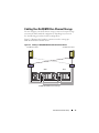 13
13
-
 14
14
-
 15
15
-
 16
16
-
 17
17
-
 18
18
-
 19
19
-
 20
20
-
 21
21
-
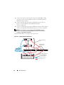 22
22
-
 23
23
-
 24
24
-
 25
25
-
 26
26
-
 27
27
-
 28
28
-
 29
29
-
 30
30
-
 31
31
-
 32
32
-
 33
33
-
 34
34
-
 35
35
-
 36
36
-
 37
37
-
 38
38
-
 39
39
-
 40
40
-
 41
41
-
 42
42
-
 43
43
-
 44
44
-
 45
45
-
 46
46
-
 47
47
-
 48
48
-
 49
49
-
 50
50
-
 51
51
-
 52
52
-
 53
53
-
 54
54
-
 55
55
-
 56
56
-
 57
57
-
 58
58
-
 59
59
-
 60
60
-
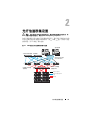 61
61
-
 62
62
-
 63
63
-
 64
64
-
 65
65
-
 66
66
-
 67
67
-
 68
68
-
 69
69
-
 70
70
-
 71
71
-
 72
72
-
 73
73
-
 74
74
-
 75
75
-
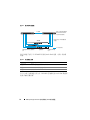 76
76
-
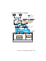 77
77
-
 78
78
-
 79
79
-
 80
80
-
 81
81
-
 82
82
-
 83
83
-
 84
84
-
 85
85
-
 86
86
-
 87
87
-
 88
88
-
 89
89
-
 90
90
-
 91
91
-
 92
92
-
 93
93
-
 94
94
-
 95
95
-
 96
96
-
 97
97
-
 98
98
-
 99
99
-
 100
100
-
 101
101
-
 102
102
-
 103
103
-
 104
104
-
 105
105
-
 106
106
-
 107
107
-
 108
108
-
 109
109
-
 110
110
-
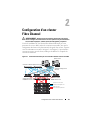 111
111
-
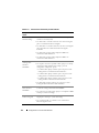 112
112
-
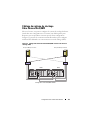 113
113
-
 114
114
-
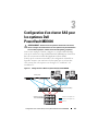 115
115
-
 116
116
-
 117
117
-
 118
118
-
 119
119
-
 120
120
-
 121
121
-
 122
122
-
 123
123
-
 124
124
-
 125
125
-
 126
126
-
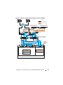 127
127
-
 128
128
-
 129
129
-
 130
130
-
 131
131
-
 132
132
-
 133
133
-
 134
134
-
 135
135
-
 136
136
-
 137
137
-
 138
138
-
 139
139
-
 140
140
-
 141
141
-
 142
142
-
 143
143
-
 144
144
-
 145
145
-
 146
146
-
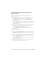 147
147
-
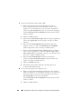 148
148
-
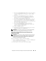 149
149
-
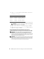 150
150
-
 151
151
-
 152
152
-
 153
153
-
 154
154
-
 155
155
-
 156
156
-
 157
157
-
 158
158
-
 159
159
-
 160
160
-
 161
161
-
 162
162
-
 163
163
-
 164
164
-
 165
165
-
 166
166
-
 167
167
-
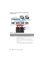 168
168
-
 169
169
-
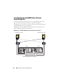 170
170
-
 171
171
-
 172
172
-
 173
173
-
 174
174
-
 175
175
-
 176
176
-
 177
177
-
 178
178
-
 179
179
-
 180
180
-
 181
181
-
 182
182
-
 183
183
-
 184
184
-
 185
185
-
 186
186
-
 187
187
-
 188
188
-
 189
189
-
 190
190
-
 191
191
-
 192
192
-
 193
193
-
 194
194
-
 195
195
-
 196
196
-
 197
197
-
 198
198
-
 199
199
-
 200
200
-
 201
201
-
 202
202
-
 203
203
-
 204
204
-
 205
205
-
 206
206
-
 207
207
-
 208
208
-
 209
209
-
 210
210
-
 211
211
-
 212
212
-
 213
213
-
 214
214
-
 215
215
-
 216
216
-
 217
217
-
 218
218
-
 219
219
-
 220
220
-
 221
221
-
 222
222
-
 223
223
-
 224
224
-
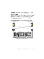 225
225
-
 226
226
-
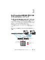 227
227
-
 228
228
-
 229
229
-
 230
230
-
 231
231
-
 232
232
-
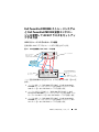 233
233
-
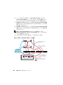 234
234
-
 235
235
-
 236
236
-
 237
237
-
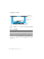 238
238
-
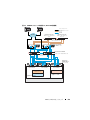 239
239
-
 240
240
-
 241
241
-
 242
242
-
 243
243
-
 244
244
-
 245
245
-
 246
246
-
 247
247
-
 248
248
-
 249
249
-
 250
250
-
 251
251
-
 252
252
-
 253
253
-
 254
254
-
 255
255
-
 256
256
-
 257
257
-
 258
258
-
 259
259
-
 260
260
-
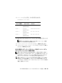 261
261
-
 262
262
-
 263
263
-
 264
264
-
 265
265
-
 266
266
-
 267
267
-
 268
268
-
 269
269
-
 270
270
-
 271
271
-
 272
272
-
 273
273
-
 274
274
-
 275
275
-
 276
276
-
 277
277
-
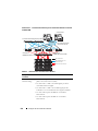 278
278
-
 279
279
-
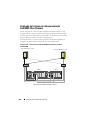 280
280
-
 281
281
-
 282
282
-
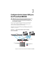 283
283
-
 284
284
-
 285
285
-
 286
286
-
 287
287
-
 288
288
-
 289
289
-
 290
290
-
 291
291
-
 292
292
-
 293
293
-
 294
294
-
 295
295
-
 296
296
-
 297
297
-
 298
298
-
 299
299
-
 300
300
-
 301
301
-
 302
302
-
 303
303
-
 304
304
-
 305
305
-
 306
306
-
 307
307
-
 308
308
-
 309
309
-
 310
310
-
 311
311
-
 312
312
-
 313
313
-
 314
314
-
 315
315
-
 316
316
-
 317
317
-
 318
318
-
 319
319
-
 320
320
-
 321
321
-
 322
322


Dell Supported Configurations for Oracle Database 10g R2 for Windows Guía del usuario
- Tipo
- Guía del usuario
en otros idiomas
- français: Dell Supported Configurations for Oracle Database 10g R2 for Windows Mode d'emploi
- English: Dell Supported Configurations for Oracle Database 10g R2 for Windows User guide
- Deutsch: Dell Supported Configurations for Oracle Database 10g R2 for Windows Benutzerhandbuch
- 日本語: Dell Supported Configurations for Oracle Database 10g R2 for Windows ユーザーガイド
Artículos relacionados
-
Dell /EMC CX4i El manual del propietario
-
Dell PowerVault 3000 Guía de instalación
-
-
-
-
-
-
-
-
Otros documentos
-
Bosch Appliances 1200 Manual de usuario
-
Promise Technology SUPERTRAK EX4350 Manual de usuario
-
Optimus TP-10/V Manual de usuario
-
 Oracle Audio Technologies SG-XPCIE2FC-ATCA-Z Manual de usuario
-
-
Oracle StorageTek SG-PCIE2FC-ATCA-Z Manual de usuario
-
promethean ActiVote Guía de inicio rápido
