Faber Inca Smart 28 Stainless Steel 240 El manual del propietario
- Categoría
- Campanas de cocina
- Tipo
- El manual del propietario
Este manual también es adecuado para

INSP28SS400
INSP28SS600
INCA SMART
Installation Instructions
Use and Care Information
Instructions d'installation
Utilisez et d'entretien
Instrucciones de instalación
Información de uso y cuidado

2
READ AND SAVE THESE INSTRUCTIONS BEFORE YOU START
INSTALLING THIS RANGE HOOD
WARNING: - TO REDUCE THE RISK OF A RANGE TOP GREASE FIRE:
a) Never leave surface units unattended at high settings. Boilovers cause smoking and greasy
spillovers that may ignite. Heat oils slowly on low or medium setting.
b)AlwaysturnhoodONwhencookingathighheatorwhenambeingfood(i.e.Crepes
Suzette, Cherries Jubilee, Peppercorn Beef Flambé).
c) Clean ventilating fans frequently. Grease should not be allowed to accumulate on fan or
lter.
d) Use proper pan size. Always use cookware appropriate for the size of the surface element.
WARNING: - TO REDUCE THE RISK OF INJURY TO PERSONS IN THE EVENT OF A RANGE
TOP GREASE FIRE, OBSERVE THE FOLLOWING*:
a)SMOTHERFLAMESwithaclose-ttinglid,cookiesheet,ormetaltray,thenturnoffthe
burner.BECAREFULTOPREVENTBURNS.Iftheamesdonotgooutimmediately
EVACUATE AND CALL THE FIRE DEPARTMENT.
b) NEVER PICK UP A FLAMING PAN - You may be burned.
c) DO NOT USE WATER, including wet dishcloths or towels - a violent steam explosion will
result.
d) Use an extinguisher ONLY if:
1. You know you have a Class ABC extinguisher, and you already know how to operate
it.
2. Thereissmallandcontainedintheareawhereitstarted.
3. Theredepartmentisbeingcalled.
4. Youcanghttherewithyourbacktoanexit.
* Based on "Kitchen Firesafety Tips" published by NFPA
WARNING - TO REDUCE THE RISK OF FIRE OR ELECTRIC SHOCK, do not use this fan with
any solid-state speed control device.
WARNING - TO REDUCE THE RISK OF FIRE, ELECTRICAL SHOCK, OR INJURY TO PERSONS,
OBSERVE THE FOLLOWING:
1. Use this unit only in the manner intended by the manufacturer. If you have any questions,
contact the manufacturer.
2. Before servicing or cleaning unit, switch power off at service panel and lock the service
disconnecting means to prevent power from being switched on accidentally. When the
service disconnecting means cannot be locked, securely fasten a prominent warning
device, such as a tag, to the service panel.
CAUTION: For General Ventilating Use Only. Do Not Use To Exhaust Hazardous or Explosive
Materials and Vapors.
WARNING - TO REDUCE THE RISK OF FIRE, ELECTRICAL SHOCK, OR INJURY TO PERSONS,
OBSERVE THE FOLLOWING:
1. InstallationWorkAndElectricalWiringMustBeDoneByQualiedPerson(s)InAccordance
With All Applicable Codes And Standards, Including Fire-Rated Construction.
2. Sufcientairisneededforpropercombustionandexhaustingofgasesthroughthe
ue(chimney)offuelburningequipmenttopreventbackdrafting.Followtheheating
equipment manufacturer's guideline and safety standards such as those published by
theNationalFireProtectionAssociation(NFPA),andtheAmericanSocietyforHeating,
RefrigerationandAirConditioningEngineers(ASHRAE),andthelocalcodeauthorities.
3. When cutting or drilling into wall or ceiling, do not damage electrical wiring and other
hidden utilities.

3
4. Ducted fans must always be vented to the outdoors.
ALL WALL AND FLOOR OPENINGS WHERE THE RANGE HOOD IS INSTALLED MUST
BE SEALED.
This Range Hood requires at least 24" of clearance between the bottom of the Range Hood
and the cooking surface or countertop. This hood has been approved by UL at this distance from
the cooktop.
This minimum clearance may be higher depending on local building codes. For gas cooktops and
combination ranges, a minimum of 30" is recommended and may be required.
Overhead cabinets on both sides of this unit must be a minimum of 18" above the cooking surface
or countertop. Consult the cooktop or range installation instructions given by the manufacturer
before making any cutouts.
MOBILE HOME INSTALLATION The installation of this Range Hood must conform to the Manufactured
Home Construction and Safety Standards, Title 24 CFR, Part 3280 (formerly Federal Standard
for Mobile Home Construction and Safety, Title 24, HUD, Part 280). See Electrical Requirements.
• Venting system MUST terminate outside the home.
• DO NOT terminate the ductwork in an attic or other enclosed space.
• DO NOT use 4" laundry-type wall caps.
• Flexible-type ductwork is not recommended.
• DO NOT obstruct the ow of combustion and ventilation air.
• Failure to follow venting requirements may result in a re.
WARNING
!
VENTING REQUIREMENTS
Determine which venting method is best for your application. Ductwork can extend either through
the wall or the roof.
The length of the ductwork and the number of elbows should be kept to a minimum to provide efcient
performance. The size of the ductwork should be uniform. Do not install two elbows together. Use
duct tape to seal all joints in the ductwork system. Use caulking to seal exterior wall or oor opening
around the cap.
Flexible ductwork is not recommended. Flexible ductwork creates back pressure and air turbulence that
greatly reduces performance.
Make sure there is proper clearance within the wall or oor for exhaust duct before making cutouts.
Do not cut a joist or stud unless absolutely necessary. If a joist or stud must be cut, then a supporting
frame must be constructed.
WARNING - To Reduce The Risk Of Fire, Use Only Metal Ductwork.
CAUTION-Toreduceriskofreandtoproperlyexhaustair,besuretoductairoutside–Do
not vent exhaust air into spaces within walls or ceilings or into attics, crawl spaces, or garages.
Cold Weather installations
An additional back draft damper should be installed to minimize backward cold air ow and a
nonmetallic thermal break should be installed to minimize conduction of outside temperatures
as part of the vent system. The damper should be on the cold air side of the thermal break.
The break should be as close as possible to where the vent system enters the heated portion
of the house.

4
• Electrical ground is required on this Range Hood.
• If cold water pipe is interrupted by plastic, nonmetallic gaskets or other materials, DO NOT
use for grounding.
• DO NOT ground to a gas pipe.
• DO NOT have a fuse in the neutral or grounding circuit. A fuse in the neutral or grounding
circuit could result in electrical shock.
• Check with a qualied electrician if you are in doubt as to whether the Range Hood is
properly grounded.
• Failure to follow electrical requirements may result in a re.
WARNING
!
StateofCaliforniaProposition65Warning(USonly)
WARNING
This product contains chemicals known to the State of California to cause cancer and birth
defects or other reproductive harm.
For more information go to www.P65Warnings.ca.gov
ELECTRICAL REQUIREMENTS
A 120 volt, 60 Hz AC-only electrical supply is required on a separate 15 amp fused circuit. A time-de-
lay fuse or circuit breaker is recommended. The fuse must be sized per local codes in accordance
with the electrical rating of this unit as specied on the serial/rating plate located inside the unit near
the eld wiring compartment.

5
RANGE HOOD DIMENSIONS 28"
47 "

6
MIN. 24" OVER ELECTRIC
INSTALLATION HEIGHT REQUIREMENTS
MIN. 30" OVER GAS

7
12a Pozi Screws (1/8" x 5/8")
10
12b Pozi Screws (1/8" x 1/2")
4
12e Torx Screws (1/8" x 3/8")
2
Torx Screwdriver
Pozi Screwdriver
H
I
H
I
H
I
12b
12e
8
12a
MAIN PARTS
Components
Ref. Qty. Product Components
1 1 Hood Body, complete with: Controls, Light, Filters,Blower.
8 1 Recirculation Vent Grill
10 2 Flap
11 1 Ring
Ref. Qty. Installation Components
12a 10 Screws (for hood installation)
12b 4 Screws 1/8"x1/2" (for Cover installation)
12e 2 Screws 1/8"x3/8" (for Recirculation Vent Grill mounting)
Qty. Documentation
1 Instruction Manual
H
I
10
H
I
11

8
Available Accessories
Parts needed
- 6" Round Metal ductwork .
Direct Connect Wiring Box sku # WIREBOX
Liner 30" Stainless #LINE30ST
Liner 36" Stainless #LINE36ST
Activated Charcoal Filter sku #; FILTER1
Activated Charcoal Filter sku #; FILTER1LL
Created by
-
Denomination
-
Lang EN
Sheet
1
/1
Modif.by
Approved by
Approval date
Doc. status
Drawing N.
NEW_DRAWING_BOX
Rev
01
Two men required for installation Wear work gloves for safety

9
LINER DIMENSIONS
Version 09/14 - Page 4
SIDE VIEW / LA PERSPECTIVE DE CÔTÉ
FRONT VIEW / LA PERSPECTIVE DE FRONT
BOTTOM VIEW / LA PERSPECTIVE DE BAS
Standard Liner 36 Stainless (LINE36ST)
designed for 36” wide installations
Cadre Standard 36 Axier Inoxydable (LINE36ST)
peut être employée les hottes encastrable sur mesure de 36"
Standard Liner 30 Stainless (LINE30ST)
designed for 30” wide installations
Cadre Standard 30 Axier Inoxydable (LINE30ST)
peut être employée les hottes encastrable sur mesure de 30"
Note: Standard Liners are pre-cut for installation of Inca Smart. For installations with the Inca HC SS, remove the additional perforated section.
Note: Les Cadres Standard sont précoupés pour l'installation de l'Inca Smart. Pour des installations avec L'Inca HC SS, enlevez la section perforée
additionnelle.
RANGEHOOD DIMENSIONS / DIMENSIONS DE LA HOTTE
LINER DIMENSIONS / DIMENSIONS DU CADRE
Pre-Planning Your Installation -
Important: The recommended height to install this hood off the cooktop is
a minimum of 24" and a maximum of 30” for maximum effectiveness. Also consult the cooktop manufacturer’s
recommendation.
Planiez votre installation - Important : La hauteur recommandée pour installer cette hotte au-dessus de la
surface de cuisson est d’un minimum de 24” et d’un maximum de 30” pour un maximum d’efcacité. De plus,
nous vous recommandons consulter le manuel de recommandations du fabricant de la surface de cuisson.
NOTE: Remove the metal packaging support
piece from the top of the hood before
installation (SEE RIGHT)
NOTE : Enlevez le morceau de empaquetage de
soutien en métal du dessus du hotte avant
installation (VOYEZ BIEN)
Pre-Planning your Installation - Important: The recommended height to install this hood off the
cooktop is a minimum of 24" and a maximum 30" for maximum effectiveness. Also consult the
cooktop manufacturer's recommendation.
StandardLiner30Stainless(LINE30ST)designedfor30”wideinstallations
StandardLiner36Stainless(LINE36ST)designedfor36”wideinstallations

10
FOR INSTALLATION WITH LINERS
When building a custom hood, always
follow all applicable codes and
standards.
WARNING
!
The Inca Smart can be used in
standard 30" or 36" wide cabinetry
or with custom hoods 30" wide
and up.
For custom/wood hoods,
choose either YOUR OWN
custom liner or our Standard
Liner designed for 30" and
36" wide installations. Liners
create a perfectly - sealed,
non-combustible nish for the
underside of your custom/
wood hood.
The Standard Liners are made
up of two sections: a larger,
rear section (pre-cut out for
insertion of the Inca Smart)
and a front section for a total
adjustable depth between 16"
and 17 7/8".
!!! IMPORTANT NOTE: DO NOT
REMOVE THE ADDITIONAL
PERFORATED SECTION AROUND
THE PRE-CUT-OUT WHEN
INSTALLING THE STANDARD
LINER WITH THE INCA SMART
MODEL.
Consider the shape, size,
and weight of the Inca Smart
and Liner to determine the
conguration of the custom/
wood hood.
See RANGEHOOD DIMENSIONS
AND LINER DIMENSIONS.
1. The custom/wood hood must have a sturdy base (3/4" plywood
recommended) to accomodate the cut-out for the Inca Smart. The base
must be recessed to accomodate the height of the Liner (see LINER
DIMENSIONS). The Liner attaches to the bottom of the base using
screws appropriate for the size and material of your custom/wood hood.
The Inca Smart inserts into the cut-out in the Liner and base.
2. Position the rear section of the Liner so that it abuts the back edge of
your custom/wood hood. Using a pen, trace the outline of the pre-cut out.
Remove the Liner and proceed to MAKE YOUR CUT-OUTS.
Install both sections of the Liner and proceed to INSTALL THE
RANGEHOOD.
Version 09/14 - Page 5
The Inca Smart requires 5" round ductwork. To ensure that the blower performs to its
highest possible capacity, ductwork should be as short and straight as possilbe.
Make your ductrun as straight and short as possible. The ductrun should not exceed 25
equivalent feet if ducted with the required minimum of 5" round duct. Count 45º angles
as 3 feet, 90º elbows as 5 feet, and 90º at elbows as 12 feet.
For best results, use no more than three 90° elbows. Make sure that there is a minimum
of 24" of straight duct between elbows if more than one is used. Do not install two
elbows together. If you must elbow right away, do it as far away from the hood's
exhaust opening as possible.
TOOLS NEEDED FOR INSTALLATION
• Saber Saw or Jig Saw
• Drill
• 1 1/4" Wood Drill Bit
• Pliers
• Phillips Screwdriver
• Wire Stripper or Utility Knife
• Metal Snips
• Measuring Tape or Ruler
• Level
• Pencil
• Caulking Gun
• Duct Tape
PLAN YOUR DUCTWORK
The Inca Smart can be used in
standard 30" or 36" wide cabinetry
or with custom hoods 30" wide
and up.
For custom/wood hoods, choose
either YOUR OWN custom liner or
our Standard Liner designed for 30"
and 36" wide installations. Liners
create a perfectly-sealed, non-
combustible nish for the underside
of your custom/wood hood.
The Standard Liners are made
up of two sections: a larger, rear
section (pre-cut out for insertion of
the Inca Smart) and a front section
for a total adjustable depth between
16" and 17
7/8".
!!! IMPORTANT NOTE: DO NOT
REMOVE THE ADDITIONAL
PERFORATED SECTION
AROUND THE PRE-CUT-
OUT WHEN INSTALLING
THE STANDARD LINER WITH
THE INCA SMART MODEL.
THIS PERFORATION IS ONLY
REMOVED FOR USE WITH THE
INCA HC SS MODEL.
Consider the shape, size, and
weight of the Inca Smart and Liner
to determine the configuration
of the custom/wood hood. See
RANGEHOOD DIMENSIONS AND
LINER DIMENSIONS on Page 4.
FOR INSTALLATIONS WITH LINERS
PARTS SUPPLIED FOR INSTALLATION
• 1 Backdraft Damper
• 10 Screws
• Field Wiring Box
• 1 Literature Package
PARTS NEEDED FOR INSTALLATION
• 2 Conduit Connectors
• Power Supply Cable
• Scews for Field Wiring Box
• 1 Wall or Roof Cap
• All Metal Ductwork
OPTIONAL ACCESSORIES AVAILABLE
• Charcoal Filter Kit
For recirculating installations only,
replace charcoal lters as needed
part # FILTER4
• Liners
Create a perfectly-sealed, non-combustible
perimeter around the Inca Smart. Depth adjustable
from 16" - 17
7/8"
.
Standard Liner 30 Stainless - part #
LINE30ST
Standard Liner 36 Stainless - part # LINE36ST
CUSTOM/WOOD
HOOD
STANDARD LINER
INCA SMART
WARNING
!
When building a custom hood,
always follow all applicable
codes and standards.
1. The custom/wood hood must have a sturdy base (3/4" plywood recommended) to accomodate
the cut-out for the Inca Smart. The base must be recessed to accomodate the height of the
Liner (see LINER DIMENSIONS on Page 4). The Liner attaches to the bottom of the base
using screws appropriate for the size and material of your custom/wood hood. The Inca Smart
inserts into the cut-out in the Liner and base.
2. Position the rear section of the Liner so that it abuts the back edge of your custom/wood
hood. Using a pen, trace the outline of the pre-cut out. Remove the Liner and proceed to MAKE
YOUR CUT-OUTS on Page 6. Install both sections of the Liner and proceed to INSTALL THE
RANGEHOOD on Page 6.
CUSTOM/WOODH
HOOD
STANDARD LINER
INCA SMART

11
Choose your ducting method
Rear
Top
6"
Non Ducted - RecirculationDucted Venting Installation
Requires purchase of Activated
Charcoal Accessory #Filter1
Caution: If an elbow is required,
do it as far away from the hood's
exhaust opening as possible.

12
1
Remove grease lters and set aside.
INSTALL THE RANGE HOOD
2
Remove the bottom of the Range Hood by pulling as shown.

13
3
The Hood can be installed directly on the underside of the cabinet (minimum 24" for electric ranges
and 30" for gas ranges).
Create an opening in the bottom of the Cabinet, as shown.
10 1/2”
1/2”
26” 5/8
10 1/2”
1/2”
26” 5/8
1/2”
10 1/4”
26” 5/8
1/2”
Attention: The cabinet must be accessible so that you can access the hood cable and
plug in the future, after installing the product

14
10 1/2”
1/2”
26” 5/8
Min.9/16"
Max 1" 3/16
Vf
Insert the hood until the side supports snap into place.
Lock in position by tightening the screws Vf from underneath the hood.
4
Fasten using the 10 screws 12a provided.
5

15
Replace the bottom of the Range Hood by 4 screws 12b as shown.
Place the grease lters in the hood
6
7
12b

16
Ducted Venting Installation
8
Non Ducted -
Recirculation Option
Install the 2 Flap 10 included with the
Range Hood as shown.
Break the 4 pre-cutting pieces and install
the Ring 11 included with the Range
Hood before connecting to the ductwork.
Install Roof or Wall Cap purchased
separately. Connect the 6" metal duct-
work to the Roof or Wall Cap and then
attach ductwork.
´
For Non-Ducted Recirculation venting route
the ductwork to a location above the hood
where the discharge is vented back into the
room.
Use the included Recirculation Vent Grill to
cover the opening. Secure the grill with the
2 screws provided in the Install Kit.
Required Activated Charcoal
Filter Accessory - sku #FILTER1
or #FILTER1LL
CHOOSE YOUR DUCTING METHOD
12e
8
Torx Screwdriver
10
11

17
Direct Connect Wiring Box
Accessory sku # WIREBOX
(purchased separately)
Created by
-
Denomination
-
Lang EN
Sheet
1
/1
Modif.by
Approved by
Approval date
Doc. status
Drawing N.
NEW_DRAWING_BOX
Rev
01
ELECTRICAL INSTALLATION WITH
OPTIONAL WIRING BOX
For Permanent wiring Installation-Use only
with Listed Range Hood Wiring Box kit
sku # WIREBOX, manufactured by Faber.
Max. 33 7/16”
9
ELECTRICAL INSTALLATION WITH CONNECTION CABLE
GROUNDING INSTRUCTIONS
This appliance must be grounded. In the event of an electrical short circuit, grounding
reduces the risk of electric shock by providing an escape wire for the electric current.
This appliance is equipped with a cord having a grounding wire with a grounding
plug. The plug must be plugged into an outlet that is properly installed and grounded.
WARNING - Improper grounding can result in a risk of electric shock.
Consult a qualied electrician if the grounding instructions are not completely under-
stood, or if doubt exists as to whether the appliance is properly grounded.
Do not use an extension cord. If the power supply cord is too short, have a qualied
electrician install an outlet near the appliance.

18
1
2
10
For Non-Ducted Recirculation Option
Attach each charcoal lter to the black
grid on each side of the blower. Press the
charcoal lter tightly to the black grid on the
blower side and rotate the lter clockwise
(towards the front of the insert hood) until
it locks into place. Turn counterclockwise
(towards the back of the insert hood) to
remove.
Required Activated Charcoal Filter
Accessory - sku sku #FILTER1 or
#FILTER1LL

19
USE AND CARE INFORMATION
For Best Results
Start the Range Hood several minutes before cooking to develop proper airow. Allow the
Range Hood to operate for several minutes after cooking is complete to clear all smoke and
odors from the kitchen.
Button Function
LED indicator light (L) - indicates current speed with color
Green - speed 1
Orange - speed 2
Red - speed 3
Flashing Red - intensive speed
Light On/Off Button
On/Off switch for the lights.
Press the button to turn the light ON and press again to turn it OFF.
Blower On/Off Button
On/Off button for the blower.
Press the button to turn the blower ON to speed one (indicated by green LED)
and press again to turn the hood off.
Blower Speed 2
Press this button to turn the hood onto speed #2. (indicated by orange LED).
Blower Speed 3 / Intensive
Press this button to turn the hood onto speed #3. (indicated by solid red LED)
Hold down the speed 3 button for 2 seconds to activate the intensive speed.
The intensive speed setting is indicated by a blinking red light.
This operates the hood for 10 minutes on the highest speed and then returns to
the previous speed.

20
Cleaningmetalgreaselters
The metal grease lters can be cleaned in hot detergent
solution or washed in the dishwasher. They should be
cleaned every 2 months use, or more frequently if use
is particularly heavy.
• Remove the lter, pushing the lever towards the back
of the unit and at the same time pulling downward.
• Wash the lter without bending it, leave it to dry
thoroughly before replacing (if the surface of the lter
changes color over time, this will have absolutely no
effect on its efciency).
• Replace, taking care to ensure that the handle faces
forward.
• Cleaning in dishwasher may dull the nish of the
metal grease lter.
• No water can be present in lters before installing
back in hood.
Cleaning Exterior surfaces
Cleaning Exterior surfaces:
Please note, abrasives and scouring agents can scratch
range hood nishes and should not be used to clean
nished surfaces.
Stainless Steel nish cleaning instructions:
Clean exterior surfaces with a commercially available
stainless steel cleaner.
Painted Gray nish cleaning instructions:
Clean exterior surfaces with hot soapy water.
Replacing Activated Charcoal Filter
The Activated Charcoal Filters are not washable
and cannot be regenerated, and must be replaced
approximately every 4 months of operation, or more
frequently with heavy usage.
• Remove the Filter, pushing it towards the back of the
unit and at the same time pulling downward.
• Remove the saturated Activated Charcoal Filters,
as indicated (A).
• Fit the new Filters, as indicated (B).
• Replace, taking care to ensure that the handle faces
forwards.
Caution: When used in recirculation mode, to
Reduce the Risk of Fire and Shock use only con-
version kit Model FILTER1 or FILTER1LL.

21
Light Bulb Replacement
• Remove grease lters and set aside.
• Remove the bottom of the Range Hood by 4 screws 12b as shown.
• Replace the lamp with a new one of the same type.
• Replace the bottom of the Range Hood by 4 screws 12b.
• Replace the grease lters.
E12 self-ballasted led lamps –
listed in accordance with ul 1993/
nmxj-578/1-ance/ csa c22.2 No.
1993
12b

22
WIRING DIAGRAM
0 1 2 3 4 5 6 7 8 9
R
P
P
H90_617
01
Drawing N : Rev :
Modif. by
Doc.status
Do not get quotas from the drawing do not bring
modifications without authorization of techincal office.
According to the law we reserve the own of the present
drawing with reproduction prohibition partial or total.
Approved date
Modification description
Approved by
WIRING DIAGR.M8/4V ESZ LED
Doc Type
Denomination
Creation date
17.Ott.2019
DOLCE CORRADO
Created by
991.0601.656
Code
F
110-127V
60Hz
N
Y-G
123
654
987
PNK
M8-4V
BRW
ORG
BRWWHT
L-BBLU
BLK
GRY
SIDE
INSERT
CABLE
BLU
WHT
GRY
123
654
789
BLU
PNK
BRW
WHT
Y-G
L-B
BLU
1
2
3
4
5
6
BLK
BRW
WHT
Y-G
PNK
V1
MC
F
V2
ESZ
BLK
0-1 MOTOR
2 SPEED 3 SPEED 0-1 LIGHT
N
L
V4
L
V3
WHT
1
2
3
4
5
6
L-B
ORG
BLK
ORG
GRY
ORG
LED LAMP
ORG
INSP28SS400 INSP28SS600

23
January 4, 2016
FABER CONSUMER WARRANTY & SERVICE
All Faber products are warranted against any defect in materials or workmanship for the original purchaser
for a period of 1 year from the date of original purchase (requires proof of purchase). This warranty covers
labor and replacement parts. Faber, at its option, may repair or replace the product or components
necessary to restore the product to good working condition. To obtain warranty service, contact the dealer
from whom you purchased the range hood, or the local Faber distributor. If you cannot identify a local Faber
distributor, contact us at (508) 358-5353 for the name of a distributor in your area.
The following is not covered by Faber's warranty:
1. Service calls to correct the installation of your range hood, to instruct you how to use your range hood, to
replace or repair house fuses or to correct house wiring or plumbing.
2. Service calls to repair or replace range hood light bulbs, fuses or filters. Those consumable parts are
excluded from warranty coverage.
3. Repairs when your range hood is used for other than normal, single-family household use.
4. Damage resulting from accident, alteration, misuse, abuse, fire, flood, acts of God, improper installation,
installation not in accordance with electrical or plumbing codes or Faber documentation, or use of products
not approved by Faber.
5. Replacement parts or repair labor costs for units operated outside the United States or Canada, including
any non-UL or C-UL approved Faber range hoods.
6. Repairs to the hood resulting from unauthorized modifications made to the range hood.
7. Expenses for travel and transportation for product service in remote locations and pickup and delivery
charges. Faber range hoods should be serviced in the home.
THIS WARRANTY DOES NOT ALLOW RECOVERY OF INCIDENTAL OR CONSEQUENTIAL DAMAGES, INCLUDING, WITHOUT
LIMITATION, DIRECT, INDIRECT, INCIDENTAL, SPECIAL OR CONSEQUENTIAL DAMAGES, PERSONAL INJURY/WRONGFUL
DEATH OR LOST PROFITS FABER WARRANTY IS LIMITED TO THE ABOVE CONDITIONS AND TO THE WARRANTY PERIOD
SPECIFIED HEREIN AND IS EXCLUSIVE. EXCEPT AS EXPRESSLY SPECIFIED IN THIS AGREEMENT, FABER DISCLAIMS ALL
EXPRESS OR IMPLIED CONDITIONS, REPRESENTATIONS, AND WARRANTIES INCLUDING, WITHOUT LIMITATION, ANY
IMPLIED WARRANTIES OF MERCHANTABILITY OR FITNESS FOR A PARTICULAR PURPOSE
.
This warranty gives you specific legal rights that may vary from state to state.
Model#: ______________________________ Serial #: _____________________________

24
VEUILLEZ LIRE ET CONSERVER LA PRÉSENTE NOTICE AVANT
DE COMMENCER L'INSTALLATION DE LA HOTTE DE CUISINE
AVERTISSEMENT : - POUR RÉDUIRE LE RISQUE D'UN FEU DE GRAISSE SUR LA
TABLE DE CUISSON :
a) Ne laissez jamais sans surveillance les éléments de la surface de cuisson à
température élevée. Les bouillonnements excessifs peuvent provoquer de la fumée
et lesdébordementsde graisse peuvent s'enammer. L'huiledoit être chauffée
lentement, à une température basse ou moyenne.
b) Assurez-vous de toujours mettre en marche la hotte lorsque vous cuisinez à
températureélevéeoupréparezunmetsambé(p.ex.crêpesSuzette,cerisesjubilé,
bœufambé).
c) Nettoyez régulièrement les ventilateurs d'aspiration. Assurez-vous de ne pas laisser
delagraisses'accumulersurleventilateurouleltre.
d)Utiliseztoujoursdespoêlesetcasserolesdelatailleappropriée.Utiliseztoujours
des ustensiles de cuisine de la taille adaptée à celle de l'élément chauffant.
A
VERTISSEMENT : - POUR PRÉVENIR LES BLESSURES EN CAS DE FEU DE GRAISSE
SUR LA TABLE DE CUISSON, SUIVEZ LES RECOMMANDATIONS SUIVANTES* :
a) ÉTOUFFEZ LES FLAMMES à l'aide d'un couvercle hermétique, d'une plaque à
biscuits ou d'un plateau métallique, puis éteignez le brûleur. FAITES ATTENTION
AUX BRÛLURES. Si le feu ne s'éteint pas immédiatement, QUITTEZ LES LIEUX ET
APPELEZ LES POMPIERS.
b) NE PRENEZ JAMAIS UNE CASSEROLE EN FLAMME - Vous pourriez vous brûler.
c) N'UTILISEZ JAMAIS DE L'EAU, ni un linge à vaisselle ou un torchon mouillé, pour
éteindre le feu. Cela pourrait provoquer une violente explosion de vapeur.
d) Utilisez un extincteur UNIQUEMENT si :
1. Vousêtescertainqu'ils'agitd'unextincteurdeclasseABCetquevousconnaissez
bien son mode d'emploi.
2. Le feu est de faible intensité et se limite à l'endroit où il a démarré.
3. Les pompiers ont déjà été appelés.
4. Unevoiedesortiesetrouvederrièrevouspendantquevouséteignezlesammes.
*
D'après le guide « Kitchen Firesafety Tips » publié par la NFPA aux États-Unis
AVERTISSEMENT - POUR RÉDUIRE LE RISQUE D'INCENDIE OU DE CHOC ÉLECTRIQUE,
n'utilisez jamais ce ventilateur en association avec un dispositif de réglage de vitesse
à semi-conducteurs.
AVERTISSEMENT - POUR RÉDUIRE LES RISQUES D'INCENDIE, DE CHOC ÉLECTRIQUE
OU DE BLESSURE CORPORELLE, RESPECTEZ LES INSTRUCTIONS SUIVANTES :
1. Utilisez cet appareil uniquement de la façon prévue par le fabricant. Pour toute
question, communiquez avec le fabricant.
2. Avant de procéder à l'entretien ou au nettoyage de l'appareil, coupez l'alimentation
au niveau du panneau électrique et verrouillez-le pour vous assurer que l'électricité
n'est pas rétablie accidentellement. S'il n'est pas possible de verrouiller le dispositif
d'interruptiondel'alimentation,afchezdefaçonfermeetbienvisibleunavisde
danger, par exemple à l'aide d'une étiquette sur le panneau.
ATTENTION : Destiné à un usage de ventilation générale uniquement. N'utilisez pas
ce dispositif pour l'aspiration de vapeurs ou de matériaux dangereux ou
explosifs.

25
AVERTISSEMENT - POUR RÉDUIRE LES RISQUES D'INCENDIE, DE CHOC ÉLECTRIQUE
OU DE BLESSURE CORPORELLE, RESPECTEZ LES INSTRUCTIONS SUIVANTES :
1. L'installationetlebranchementélectriquedoiventêtreréalisésparuntechnicien
qualié et conformément à tous les codes et normes en vigueur, incluant ceux
concernant la construction à l'épreuve du feu.
2. An de garantir une combustion et une évacuation adéquates des gaz par les
conduites de la cheminée des appareils à combustion, une bonne aération est
nécessaire pour éviter le refoulement. Respectez les lignes directrices fournies par
le fabricant du matériel chauffant, ainsi que les normes de sécurité comme celles
publiéesparlaNationalFireProtectionAssociation(NFPA)etlaAmericanSociety
forHeating,RefrigerationandAirConditioningEngineers(ASHRAE)auxÉtats-Unis,
ainsi que les codes en vigueur dans votre région.
3. Lorsque vous faites une ouverture ou percez dans un mur ou le plafond, veillez à ne
pasendommagerleslsélectriquesoud'autresdispositifscachés.
4. Lesventilateurscanalisésdoiventtoujoursêtreraccordésàl'extérieur.
TOUTE OUVERTURE DANS LE MUR OU LE PLANCHER À PROXIMITÉ DE LA HOTTE
DOIT ÊTRE SCELLÉE.
Un espace libre d'au moins 24" est requis entre le bas de la hotte et la surface de cuisson ou
le comptoir. Cette hotte a été homologuée par l'UL à cette distance de la surface de cuisson.
L’espace libre minimal requis peut-être plus grand, selon la réglementation en matière de
construction de votre région. Pour les cuisinières à gaz et les cuisinières combinées, un espace
minimal de 30" est recommandé et pourrait être exigé.
Les armoires suspendues de chaque côté de l'appareil doivent se trouver à au moins 18" de la
surface de cuisson ou du comptoir. Consultez la notice d'installation de la surface de cuisson
ou de la cuisinière fournie par le fabricant avant de pratiquer des ouvertures.
INSTALLATION DANS UNE MAISON MOBILE L'installation de cette hotte doit être conforme
à la Partie 3280 de la norme Manufactured Home Construction and Safety Standards, Title 24
CFR (précédemment la partie 280 de la norme Federal Standard for Mobile Home Construction
and Safety, Title 24, HUD). Consultez la che technique électrique.
CRITÈRES DE VENTILATION
Déterminez quelle méthode de ventilation est mieux adaptée à votre application. Les conduits
peuvent passer par le mur ou le toit.
Pour garantir une meilleure efcacité, la longueur des conduits et le nombre de coudes doivent être
le plus limités que possible. Le diamètre des conduits devrait être uniforme. N'installez pas deux
coudes ensemble. Utilisez un ruban pour canalisations an de sceller tous les joints du système de
conduits. Utilisez un calfeutrage pour sceller les ouvertures dans le mur extérieur ou le plancher,
autour du clapet.
Il n'est pas recommandé d'utiliser des conduits exibles. Les conduits exibles provoquent une contre-
pression et de la turbulence qui diminuent grandement l'efcacité de l'appareil.
Assurez-vous que l'espace libre dans le mur ou le plancher est sufsant pour le conduit d'évacuation
avant de pratiquer les ouvertures. Ne coupez jamais une poutre ou un chevron, sauf si c'est
absolument nécessaire. S'il s'avère nécessaire de couper une poutre ou un chevron, la construction
d'un renforcement est requise.
AVERTISSEMENT - Pour réduire le risque d'incendie, utilisez uniquement des conduits métalliques.
ATTENTION - Pour réduire le risque d'incendie et pour évacuer adéquatement l'air, assurez-
vousderaccorderlesconduitsàl'extérieur–Nediffusezpasl'aird'évacuationdansdes
espaces à l'intérieur des murs ou du plafond, ou encore à l'intérieur d'un grenier, d'une
galerie technique ou d'un garage.

26
• Le système de ventilation DOIT déboucher à l'extérieur.
• NE FAITES PAS déboucher les conduits dans un grenier ou un autre endroit fermé.
• N’UTILISEZ PAS un clapet de sécheuse mural de 4".
• Il n'est pas recommandé d'utiliser des conduits exibles.
• N’ENTRAVEZ PAS le ux de l'air de combustion et de ventilation.
• Le non-respect des exigences en matière de ventilation pourrait entraîner un incendie.
AVERTISSEMENT
!
Installation dans les climats froids
Le système de ventilation doit prévoir un registre antirefoulement supplémentaire pour réduire le
ux d'air froid inverse, ainsi qu'une barrière thermique non métallique pour réduire la conduction
des températures extérieures. Le registre doit être installé du côté air froid par rapport à la
barrière thermique. La barrière thermique doit être positionnée le plus près que possible de
l'endroit où le système de ventilation pénètre dans la partie chauffée de la maison.
• Une mise à la terre électrique est requise pour cette hotte.
• N'UTILISEZ PAS un tuyau d'eau froide pour la mise à la terre si celui-ci est branché
par des joints en plastique, par des rondelles non métalliques ou d'autres matériaux.
• N'UTILISEZ PAS une conduite de gaz pour la mise à la terre.
• N'INSTALLEZ PAS un fusible sur le circuit neutre ou le circuit de mise à la terre. La
présence d'un fusible dans le circuit neutre ou de mise à la terre peut entraîner un
choc électrique.
• Consultez un électricien qualié si vous n'êtes pas certain de la mise à la terre de la
hotte.
• Le non-respect des exigences de la che technique électrique pourrait entraîner un
incendie.
AVERTISSEMENT
!
Avertissementrelatifàlaproposition65del’ÉtatdeCalifornie(États-Unisuniquement)
AVERTISSEMENT
Ce produit contient des éléments chimiques que l’État de Californie considère comme
étant cancérigènes ou causant des malformations congénitales ou d’autres troubles de la
reproduction.
Pour de plus amples renseignements, consultez le site www.P65Warnings.ca.gov
FICHE TECHNIQUE ÉLECTRIQUE
Une alimentation de courant alternatif de 120 volts à 60 Hz est requise sur un circuit à fusible distinct
de 15 ampères. Il est recommandé d'installer un fusible temporisé ou un disjoncteur. Le fusible doit
être calibré conformément aux codes en vigueur pour les caractéristiques nominales électriques
de l'appareil, indiquées sur la plaque signalétique située à l'intérieur de l'appareil, à proximité du
compartiment des câblages externes.

27
DIMENSIONS HOTTE 28"
47 "

28
MIN. 24" AU-DESSUS
D’UNE SURFACE ÉLECTRIQUE
HAUTEUR REQUISE POUR L’INSTALLATION
MIN. 30" AU-DESSUS
D’UNE SURFACE AU GAZ

29
12a Vis à tête Pozidriv (1/8" x 5/8")
10
12b Vis à tête Pozidriv (1/8" x 1/2")
4
12e Vis à tête étoile (1/8" x 3/8")
2
Tournevis étoile
Tournevis Pozidriv
H
I
H
I
H
I
12b
12e
8
12a
PIÈCES PRINCIPALES
Composants
Réf. Qté Composants du produit
1 1 Bâti de la hotte, avec : Commandes, éclairage, ltres, ventilateur.
8 1 Grille d’évent de recyclage
10 2 Volet
11 1 Anneau
Réf. Qté Composants d’installation
12a 10 vis (pour installation de la hotte)
12b 4 vis 1/8"x1/2" (pour installation du couvercle)
12e 2 vis 1/8"x 3/8" (pour montage de la grille d’évent de recyclage)
Qté Documentation
1 Mode d’emploi
H
I
10
H
I
11

30
Accessoires disponibles
Pièces requises
- Conduit métallique 6" circulaire
Boîtier de connexion directe, no d'article WIREBOX
Caisse 30" acier inoxydable, LINE30ST
Caisse 36" acier inoxydable, LINE36ST
Filtre à charbon actif, no d'article FILTER1
Filtre à charbon actif, no d'article FILTER1LL
Created by
-
Denomination
-
Lang EN
Sheet
1
/1
Modif.by
Approved by
Approval date
Doc. status
Drawing N.
NEW_DRAWING_BOX
Rev
01
Deux personnes requises
pour
l’installation
Portez des gants
par mesure de sécurité.

31
DIMENSIONS DE LA CAISSE
Version 09/14 - Page 4
SIDE VIEW / LA PERSPECTIVE DE CÔTÉ
FRONT VIEW / LA PERSPECTIVE DE FRONT
BOTTOM VIEW / LA PERSPECTIVE DE BAS
Standard Liner 36 Stainless (LINE36ST)
designed for 36” wide installations
Cadre Standard 36 Axier Inoxydable (LINE36ST)
peut être employée les hottes encastrable sur mesure de 36"
Standard Liner 30 Stainless (LINE30ST)
designed for 30” wide installations
Cadre Standard 30 Axier Inoxydable (LINE30ST)
peut être employée les hottes encastrable sur mesure de 30"
Note: Standard Liners are pre-cut for installation of Inca Smart. For installations with the Inca HC SS, remove the additional perforated section.
Note: Les Cadres Standard sont précoupés pour l'installation de l'Inca Smart. Pour des installations avec L'Inca HC SS, enlevez la section perforée
additionnelle.
RANGEHOOD DIMENSIONS / DIMENSIONS DE LA HOTTE
LINER DIMENSIONS / DIMENSIONS DU CADRE
Pre-Planning Your Installation -
Important: The recommended height to install this hood off the cooktop is
a minimum of 24" and a maximum of 30” for maximum effectiveness. Also consult the cooktop manufacturer’s
recommendation.
Planiez votre installation - Important : La hauteur recommandée pour installer cette hotte au-dessus de la
surface de cuisson est d’un minimum de 24” et d’un maximum de 30” pour un maximum d’efcacité. De plus,
nous vous recommandons consulter le manuel de recommandations du fabricant de la surface de cuisson.
NOTE: Remove the metal packaging support
piece from the top of the hood before
installation (SEE RIGHT)
NOTE : Enlevez le morceau de empaquetage de
soutien en métal du dessus du hotte avant
installation (VOYEZ BIEN)
Planicationdel’installation-Important : Il est recommandé d'installer cette hotte à une
distance d'au moins 24" de la surface de cuisson et à une distance maximale de 30” pour une
efcacité optimale. Reportez-vous également aux recommandations du fabricant de la surface
de cuisson.
Caissestandard30enacierinoxydable(LINE30ST)conçuepourlesinstallationsd'une
largeurde30”
Caissestandard36enacierinoxydable(LINE36ST)conçuepourlesinstallationsd'une
largeurde36”

32
POUR INSTALLATIONS AVEC CAISSES
Lorsque vous construisez un habillage de hotte sur
mesure, assurez-vous de toujours respecter les codes
et normes applicables.
AVERTISSEMENT
!
Le produit Inca Smart peut être
utilisé avec des armoires standards
d’une largeur de 30" ou 36", ou
encore avec un habillage de hotte
sur mesure d’une largeur de 30" et
plus.
Pour les habillages sur mesure/
en bois, choisissez soit VOTRE
PROPRE caisse sur mesure
ou nos caisses standards
conçues pour les installations
d’une largeur de 30" et 36".
Les caisses créent une nition
non combustible parfaitement
scellée pour le dessus de votre
habillage sur mesure/en bois
.
Les caisses standards sont
formées de deux sections :
une section arrière plus large
(précoupée pour l'insertion de la
hotte Inca Smart) et une section
avant, permettant de régler la
profondeur (entre 16" et 17 7/8")
!!! REMARQUE IMPORTANTE :
N’ENLEVEZ PAS LA SECTION
SUPPLÉMENTAIRE PERFORÉE
AUTOUR DE LA SECTION
PRÉCOUPÉE LORSQUE VOUS
INSTALLEZ UNE CAISSE STANDARD
AVEC LE MODÈLE INCA SMART.
Tenez compte de la forme, de la
dimension et du poids du produit
Inca Smart et de la caisse pour
déterminer la conguration de
l’habillage sur mesure/en bois.
Consultez DIMENSIONS DE HOTTE
ET DIMENSIONS DE CAISSE.
1. L'habillage de hotte sur mesure/en bois doit présenter une base
solide (contre-plaqué de 3/4" recommandé) pour permettre l'ouverture
pour la hotte Inca Smart. La base doit être amincie pour accueillir la
hauteur de la caisse (consultez DIMENSIONS DE LA CAISSE). La
caisse se xe au bas de la base à l’aide de vis adéquates pour les
dimensions et le matériau de votre habillage de hotte sur mesure/en
bois.
La hotte Inca Smart s'insère dans l'ouverture de la caisse et de la
base.
2. Placez l’arrière de la caisse en l’adossant sur le bord arrière de
votre habillage de hotte sur mesure/en bois. À l'aide d'un stylo, tracez
le contour de l'ouverture précoupée. Retirez la caisse et PRATIQUEZ
VOS OUVERTURES.
Installez les deux sections de la caisse et passez à l’INSTALLATION
DE LA HOTTE.
Version 09/14 - Page 5
The Inca Smart requires 5" round ductwork. To ensure that the blower performs to its
highest possible capacity, ductwork should be as short and straight as possilbe.
Make your ductrun as straight and short as possible. The ductrun should not exceed 25
equivalent feet if ducted with the required minimum of 5" round duct. Count 45º angles
as 3 feet, 90º elbows as 5 feet, and 90º at elbows as 12 feet.
For best results, use no more than three 90° elbows. Make sure that there is a minimum
of 24" of straight duct between elbows if more than one is used. Do not install two
elbows together. If you must elbow right away, do it as far away from the hood's
exhaust opening as possible.
TOOLS NEEDED FOR INSTALLATION
• Saber Saw or Jig Saw
• Drill
• 1 1/4" Wood Drill Bit
• Pliers
• Phillips Screwdriver
• Wire Stripper or Utility Knife
• Metal Snips
• Measuring Tape or Ruler
• Level
• Pencil
• Caulking Gun
• Duct Tape
PLAN YOUR DUCTWORK
The Inca Smart can be used in
standard 30" or 36" wide cabinetry
or with custom hoods 30" wide
and up.
For custom/wood hoods, choose
either YOUR OWN custom liner or
our Standard Liner designed for 30"
and 36" wide installations. Liners
create a perfectly-sealed, non-
combustible nish for the underside
of your custom/wood hood.
The Standard Liners are made
up of two sections: a larger, rear
section (pre-cut out for insertion of
the Inca Smart) and a front section
for a total adjustable depth between
16" and 17
7/8".
!!! IMPORTANT NOTE: DO NOT
REMOVE THE ADDITIONAL
PERFORATED SECTION
AROUND THE PRE-CUT-
OUT WHEN INSTALLING
THE STANDARD LINER WITH
THE INCA SMART MODEL.
THIS PERFORATION IS ONLY
REMOVED FOR USE WITH THE
INCA HC SS MODEL.
Consider the shape, size, and
weight of the Inca Smart and Liner
to determine the configuration
of the custom/wood hood. See
RANGEHOOD DIMENSIONS AND
LINER DIMENSIONS on Page 4.
FOR INSTALLATIONS WITH LINERS
PARTS SUPPLIED FOR INSTALLATION
• 1 Backdraft Damper
• 10 Screws
• Field Wiring Box
• 1 Literature Package
PARTS NEEDED FOR INSTALLATION
• 2 Conduit Connectors
• Power Supply Cable
• Scews for Field Wiring Box
• 1 Wall or Roof Cap
• All Metal Ductwork
OPTIONAL ACCESSORIES AVAILABLE
• Charcoal Filter Kit
For recirculating installations only,
replace charcoal lters as needed
part # FILTER4
• Liners
Create a perfectly-sealed, non-combustible
perimeter around the Inca Smart. Depth adjustable
from 16" - 17
7/8"
.
Standard Liner 30 Stainless - part #
LINE30ST
Standard Liner 36 Stainless - part # LINE36ST
CUSTOM/WOOD
HOOD
STANDARD LINER
INCA SMART
WARNING
!
When building a custom hood,
always follow all applicable
codes and standards.
1. The custom/wood hood must have a sturdy base (3/4" plywood recommended) to accomodate
the cut-out for the Inca Smart. The base must be recessed to accomodate the height of the
Liner (see LINER DIMENSIONS on Page 4). The Liner attaches to the bottom of the base
using screws appropriate for the size and material of your custom/wood hood. The Inca Smart
inserts into the cut-out in the Liner and base.
2. Position the rear section of the Liner so that it abuts the back edge of your custom/wood
hood. Using a pen, trace the outline of the pre-cut out. Remove the Liner and proceed to MAKE
YOUR CUT-OUTS on Page 6. Install both sections of the Liner and proceed to INSTALL THE
RANGEHOOD on Page 6.
SUR MESURE/EN BOIS
HOTTE
CAISSE STANDARD
INCA SMART

33
Choisissez la méthode de canalisation
Arrière
Haut
6"
Sans canalisation - recyclage
Installation avec ventilation canalisée
Nécessite l'achat de l'accessoire à
charbon actif Filter1
Attention : Si vous devez installer un
coude, placez-le le plus loin possible
de l’ouverture d’évacuation de la
hotte.

34
1
Retirez les ltres à graisse et mettez-les à part.
INSTALLATION DE LA HOTTE
2
Retirez le fond de la hotte en tirant comme illustré.

35
3
La hotte peut être installée directement en dessous de l’armoire (distance minimale de 24" des surfaces
de cuisson électriques et de 30" pour les surfaces de cuisson au gaz).
Pratiquez une ouverture sur le fond de l’armoire, comme illustré.
10 1/2”
1/2”
26” 5/8
10 1/2”
1/2”
26” 5/8
1/2”
10 1/4”
26” 5/8
1/2”
À noter : L’armoire doit être accessible, pour vous permettre d’atteindre le câble de la
hotte et le brancher plus tard, après l’installation du produit.

36
10 1/2”
1/2”
26” 5/8
Min. 9/16"
Max 1" 3/16
Vf
Insérez la hotte jusqu'à ce que les appuis latéraux s'enclenchent.
Verrouillez en serrant les vis Vf à partir du dessous de la hotte.
4
Fixez-la à l’aide des 10 vis 12a fournies.
5

37
Remettez en place le fond de la hotte à l’aide de 4 vis 12b comme illustré.
Placez les ltres à graisse dans la hotte
6
7
12b

38
Installation avec ventilation canalisée
8
Option de recyclage
sans canalisation
Installez les 2 volets 10 inclus avec la
hotte comme illustré.
Brisez les 4 pièces prédécoupées et
installez l’anneau 11 inclus avec la hotte,
avant de la raccorder aux conduits.
Installez le clapet de toiture ou le clapet
mural acheté séparément. Raccordez
le conduit métallique de 6" au clapet
de toiture ou au clapet mural, puis
raccordez les conduits.
´
Pour la ventilation avec recyclage sans
canalisation, dirigez les conduits à un
emplacement au-dessus de la hotte où
l'air évacué est retourné dans la pièce.
Utilisez la grille d'évent de recyclage
pour couvrir l'ouverture. Fixez la grille à
l'aide des 2 vis fournies dans la trousse
d'installation.
Filtre à charbon actif requis - No
d'article FILTER1 ou FILTER1LL
CHOISIR LA MÉTHODE DE CANALISATION
12e
8
Tournevis étoile
10
11

39
Boîtier de connexion directe
accessoire, no d'article
WIREBOX
(acheté séparément)
Created by
-
Denomination
-
Lang EN
Sheet
1
/1
Modif.by
Approved by
Approval date
Doc. status
Drawing N.
NEW_DRAWING_BOX
Rev
01
INSTALLATION ÉLECTRIQUE AVEC
BOÎTIER DE CONNEXION EN OPTION
Pour une installation avec connexion xe,
utilisez uniquement la trousse de boîtier de
connexion pour hotte indiquée,
no d'article WIREBOX, fabriquée par Faber.
Max. 33 7/16”
9
INSTALLATION ÉLECTRIQUE AVEC CÂBLE DE CONNEXION
INSTRUCTIONS DE MISE À LA TERRE
Cet appareil doit être mis à la terre. La mise à la terre réduit le risque de choc électrique
en cas de court-circuit, car elle fournit un l d'évacuation au courant électrique. Cet
appareil est muni d'un cordon présentant un l de mise à la terre, avec une che de
mise à la terre. La che doit être insérée dans une prise correctement installée et
mise à la terre.
AVERTISSEMENT - Une mise à la terre inadéquate peut entraîner un choc électrique.
Consultez un électricien qualié si vous ne comprenez pas parfaitement les instructions
de mise à la terre ou si vous avez des doutes quant à la mise à la terre de l'appareil.
N'utilisez pas de rallonge. Si le cordon d’alimentation est trop court, demandez à un
électricien qualié d’installer une prise à proximité de l'appareil.

40
1
2
10
Pour option sans canalisation, avec
recyclage d'air
Fixez les ltres à charbon à la grille noire
de chaque côté du ventilateur. Pressez
fermement le ltre à charbon contre la grille
noire de chaque côté du ventilateur et faites
tourner le ltre dans le sens des aiguilles
d'une montre (vers l'avant de la hotte
encastrable) jusqu'à ce qu'il soit verrouillé en
place. Faites tourner dans le sens contraire
des aiguilles d'une montre (vers l'arrière de
la hotte encastrable) pour l'enlever.
Filtre à charbon actif requis - No
d'article FILTER1 ou FILTER1LL

41
INFORMATION RELATIVE À L'UTILISATION ET L'ENTRETIEN
Pour de meilleurs résultats
Activez la hotte quelques minutes avant de commencer à cuisiner pour créer un ux d'air
adéquat. Laissez la hotte fonctionner quelques minutes après avoir ni de cuisiner pour
absorber toute la fumée et les odeurs de la cuisine.
Bouton Fonction
Témoin DEL (L) - la couleur permet de connaître la vitesse sélectionnée
Vert - vitesse 1
Orange - vitesse 2
Rouge - vitesse 3
Rouge clignotant - vitesse intensive
Interrupteur d’éclairage
Interrupteur Marche/Arrêt pour l'éclairage.
Appuyez sur le bouton pour mettre l'éclairage en marche, et une nouvelle fois
pour l’éteindre.
Interrupteur du ventilateur
Interrupteur Marche/Arrêt pour le ventilateur.
Appuyez sur le bouton pour mettre le ventilateur en marche à la première vitesse
(signalée par le témoin DEL vert) et appuyez de nouveau pour éteindre la hotte.
Ventilateur vitesse 2
Appuyez sur ce bouton pour faire passer la hotte à la vitesse 2 (signalée par le
témoin DEL orange).
Ventilateur vitesse 3/intensive
Appuyez sur ce bouton pour faire passer la hotte à la vitesse 3 (signalée par le
témoin DEL rouge xe)
Tenez le bouton vitesse 3 enfoncé pendant 2 secondes pour activer la vitesse
intensive.
Le réglage « vitesse intensive » est signalé par le clignotement du témoin rouge.
La hotte fonctionne alors à la vitesse maximale pendant 10 minutes, après quoi
elle retourne à la vitesse précédente.

42
Nettoyagedesltresàgraisse
métalliques
Les ltres à graisse métalliques peuvent être lavés
dans une solution d'eau chaude savonneuse ou dans le
lave-vaisselle. Ils devraient être nettoyés tous les 2 mois
d'utilisation, ou plus fréquemment en cas d'utilisation
particulièrement intensive.
• Retirez le ltre, en poussant simultanément le levier
vers l'arrière de l'appareil et en le tirant vers le bas.
• Lavez le filtre sans le plier. Laissez-le sécher
complètement avant de le réinstaller (un changement
de la couleur à la surface du ltre au l du temps n'a
aucun impact sur son efcacité).
• Remettez-le en place, en vous assurant que la poignée
se trouve vers l'avant.
• Le lave-vaisselle pourrait ternir le ni du ltre à
graisse métallique.
• Les ltres doivent être totalement secs lorsqu’ils sont
réinstallés dans la hotte.
Nettoyage des surfaces extérieures
Nettoyage des surfaces extérieures :
Veuillez noter que l’utilisation de produits abrasifs ou
solvants peut endommager la supercie de la hotte; ils ne
devraient pas être utilisés pour le nettoyage des surfaces.
Instructions pour le nettoyage de l’acier inoxydable :
Nettoyez les surfaces extérieures avec un agent
nettoyant pour l’acier inoxydable disponible sur le
marché.
Instructions pour le nettoyage des surfaces peintes
en gris :
Les surfaces extérieures doivent être lavées à l’aide
d’eau chaude savonneuse.
Remplacementdultre
à charbon actif
Les ltres à charbon actif ne sont pas lavables et ne
peuvent être régénérés. Ils doivent être remplacés
environ tous les 4 mois d'utilisation, ou plus souvent
en cas d'utilisation intensive.
• Retirez le ltre, en le poussant simultanément vers
l'arrière de l'appareil et en le tirant vers le bas.
• Retirez les ltres à charbon actif saturés comme
indiqué (A).
• Posez les nouveaux ltres, comme indiqué (B).
• Remettez-le en place, en vous assurant que la poignée
se trouve vers l'avant.
Attention : Pour réduire le risque d’incendie
ou de choc électrique lorsque l’appareil est
en mode recyclage, utilisez uniquement le
modèle FILTER1 ou FILTER1LL pour trousse de
conversion.

43
Remplacement des ampoules
• Retirez les ltres à graisse et mettez-les à part.
• Retirez le fond de la hotte avec les 4 vis 12b comme illustré.
• Remplacez l'ampoule avec une nouvelle du même type.
• Remettez en place le fond la hotte à l’aide de 4 vis 12b.
• Remettez en place les ltres à graisse.
Ampoules E12 à ballast intégré
– répondant à la norme UL 1993/
nmxj-578/1-ance/csa c22.2
No 1993
12b

44
SCHÉMA DE CÂBLAGE
0 1 2 3 4 5 6 7 8 9
R
P
P
H90_617
01
Drawing N : Rev :
Modif. by
Doc.status
Do not get quotas from the drawing do not bring
modifications without authorization of techincal office.
According to the law we reserve the own of the present
drawing with reproduction prohibition partial or total.
Approved date
Modification description
Approved by
WIRING DIAGR.M8/4V ESZ LED
Doc Type
Denomination
Creation date
17.Ott.2019
DOLCE CORRADO
Created by
991.0601.656
Code
F
110-127V
60Hz
N
Y-G
123
654
987
PNK
M8-4V
BRW
ORG
BRWWHT
L-BBLU
BLK
GRY
SIDE
INSERT
CABLE
BLU
WHT
GRY
123
654
789
BLU
PNK
BRW
WHT
Y-G
L-B
BLU
1
2
3
4
5
6
BLK
BRW
WHT
Y-G
PNK
V1
MC
F
V2
ESZ
BLK
0-1 MOTOR
2 SPEED 3 SPEED 0-1 LIGHT
N
L
V4
L
V3
WHT
1
2
3
4
5
6
L-B
ORG
BLK
ORG
GRY
ORG
LED LAMP
ORG
INSP28SS400 INSP28SS600

45
January 4, 2016
FABER CONSUMER WARRANTY & SERVICE
All Faber products are warranted against any defect in materials or workmanship for the original purchaser
for a period of 1 year from the date of original purchase (requires proof of purchase). This warranty covers
labor and replacement parts. Faber, at its option, may repair or replace the product or components
necessary to restore the product to good working condition. To obtain warranty service, contact the dealer
from whom you purchased the range hood, or the local Faber distributor. If you cannot identify a local Faber
distributor, contact us at (508) 358-5353 for the name of a distributor in your area.
The following is not covered by Faber's warranty:
1. Service calls to correct the installation of your range hood, to instruct you how to use your range hood, to
replace or repair house fuses or to correct house wiring or plumbing.
2. Service calls to repair or replace range hood light bulbs, fuses or filters. Those consumable parts are
excluded from warranty coverage.
3. Repairs when your range hood is used for other than normal, single-family household use.
4. Damage resulting from accident, alteration, misuse, abuse, fire, flood, acts of God, improper installation,
installation not in accordance with electrical or plumbing codes or Faber documentation, or use of products
not approved by Faber.
5. Replacement parts or repair labor costs for units operated outside the United States or Canada, including
any non-UL or C-UL approved Faber range hoods.
6. Repairs to the hood resulting from unauthorized modifications made to the range hood.
7. Expenses for travel and transportation for product service in remote locations and pickup and delivery
charges. Faber range hoods should be serviced in the home.
THIS WARRANTY DOES NOT ALLOW RECOVERY OF INCIDENTAL OR CONSEQUENTIAL DAMAGES, INCLUDING, WITHOUT
LIMITATION, DIRECT, INDIRECT, INCIDENTAL, SPECIAL OR CONSEQUENTIAL DAMAGES, PERSONAL INJURY/WRONGFUL
DEATH OR LOST PROFITS FABER WARRANTY IS LIMITED TO THE ABOVE CONDITIONS AND TO THE WARRANTY PERIOD
SPECIFIED HEREIN AND IS EXCLUSIVE. EXCEPT AS EXPRESSLY SPECIFIED IN THIS AGREEMENT, FABER DISCLAIMS ALL
EXPRESS OR IMPLIED CONDITIONS, REPRESENTATIONS, AND WARRANTIES INCLUDING, WITHOUT LIMITATION, ANY
IMPLIED WARRANTIES OF MERCHANTABILITY OR FITNESS FOR A PARTICULAR PURPOSE
.
This warranty gives you specific legal rights that may vary from state to state.
Model#: ______________________________ Serial #: _____________________________

46
LEA Y GUARDE ESTAS INSTRUCCIONES ANTES DE COMENZAR
A INSTALAR ESTA CAMPANA EXTRACTORA
ADVERTENCIA: - PARA REDUCIR EL RIESGO DE INCENDIO DE GRASA:
a)Nuncadejelasunidadesdesuperciedesatendidasenajustesaltos.Lasebulliciones
causan humo y derrames grasientos que pueden encenderse. Caliente los aceites
lentamente en ajustes bajos o medios.
b)Siempreenciendalacampanacuandococineafuegoaltoocuandoameealimentos
(porej.CrepesSuzette,CherriesJubilee,PeppercornBeefFlambé).
c) Limpie los sopladores con frecuencia. No se debe permitir que la grasa se acumule
enelsopladoroltro.
d)Use un tamaño de olla adecuado. Siempre use utensilios de cocina apropiados para
eltamañodelelementodesupercie.
ADVERTENCIA: - PARA REDUCIR EL RIESGO DE LESIONES A PERSONAS EN CASO
DE INCENDIO DE GRASA, TENGA CUENTA LO SIGUIENTE*:
a) APAGUE LAS LLAMAS con una tapa ajustada, bandeja para hornear galletas o bandeja
de metal, luego apague el quemador. TENGA CUIDADO PARA EVITAR QUEMADURAS.
Si las llamas no se apagan de inmediato, EVACUE Y LLAME AL DEPARTAMENTO DE
BOMBEROS.
b) NUNCA RECOJA UNA OLLA EN LLAMAS - Puede quemarse.
c) NO USE AGUA, incluidos paños de cocina húmedos o toallas; se producirá una
violenta explosión de vapor.
d) Use un extintor SOLAMENTE si:
1. Usted sabe que tiene un extintor Clase ABC y ya sabe cómo operarlo.
2. El fuego es pequeño y está contenido en el área donde comenzó.
3. Llame al departamento de bomberos.
4. Puede luchar contra el fuego con su espalda hacia una salida.
*
Basado en "Kitchen Firesafety Tips" publicado por NFPA
ADVERTENCIA - PARA REDUCIR EL RIESGO DE DESCARGA ELÉCTRICA O INCENDIO,
no use este soplador con ningún dispositivo de control de velocidad de estado.
ADVERTENCIA - PARA REDUCIR EL RIESGO DE INCENDIOS, DESCARGAS ELÉCTRICAS
O LESIONES PERSONALES, OBSERVE LO SIGUIENTE:
1. Use esta unidad solo de la manera prevista por el fabricante. Si tiene alguna
pregunta, comuníquese con el fabricante.
2. Antes de reparar o limpiar la unidad, apague el equipo en el panel de servicio
y bloquee los medios de desconexión del servicio para evitar que la energía se
encienda accidentalmente. Cuando los medios de desconexión del servicio no se
puedanbloquear,jedeformaseguraundispositivodeadvertenciaprominente,
como una etiqueta, al panel de servicio.
PRECAUCIÓN: Para uso general de ventilación solamente. No lo use para expulsar
materiales y vapores peligrosos o explosivos.
ADVERTENCIA - PARA REDUCIR EL RIESGO DE INCENDIOS, DESCARGAS ELÉCTRICAS
O LESIONES PERSONALES, OBSERVE LO SIGUIENTE:
1. El trabajo de instalación y el cableado eléctrico deben realizarlo las personas
calicadasdeacuerdocontodosloscódigosyestándaresaplicables,incluidala
construcciónconclasicacióndeincendio.
2. Senecesitasucienteaireparalacombustiónadecuadayelescapedegasesatravés

47
deltubodehumos(chimenea)delequipoquequemacombustibleparaevitarla
retrogresión. Siga las directrices del fabricante del equipo de calefacción y las normas
de seguridad tales como los publicados por la National Fire Protection Association
(NFPA),laAmericanSocietyforHeating,RefrigerationandAirConditioningEngineers
(ASHRAE)ylasautoridadesdeloscódigoslocales.
3. Al cortar o perforar la pared o el techo, no dañe el cableado eléctrico ni otros
servicios ocultos.
4. Los sopladores con conductos siempre deben tener salida al exterior.
TODAS LAS ABERTURAS DE LA PARED Y EL PISO DONDE ESTÁ INSTALADA LA
CAMPANA EXTRACTORA SE DEBEN SELLAR.
Esta campana extractora requiere al menos 24" de espacio libre entre la parte inferior de
la campana y la supercie de cocción o encimera. Esta campana ha sido aprobada por UL a
esta distancia de la placa.
Esta separación mínima puede ser mayor dependiendo de los códigos de construcción locales.
Para placas de gas y cocinas combinadas, se recomienda y puede ser necesario un mínimo
de 30 ".
Los armarios superiores a ambos lados de esta unidad deben estar a un mínimo de 18" por
encima de la supercie de cocción o la encimera. Consulte las instrucciones de instalación de
la placa o la campana proporcionadas por el fabricante antes de hacer cualquier corte.
INSTALACIÓN EN CASA MÓVIL La instalación de esta campana extractora debe cumplir con
las Normas de seguridad y construcción de viviendas prefabricadas, Título 24 CFR, Parte 3280
(anteriormente Norma federal para construcción y seguridad de casas móviles, Título 24, HUD,
Parte 280). Vea los requisitos eléctricos.
REQUISITOS DE VENTILACIÓN
Determine qué método de ventilación es mejor para su aplicación. Los conductos pueden extenderse
a través de la pared o el techo.
La longitud de los conductos y la cantidad de codos se deben mantener al mínimo para proporcionar
un rendimiento eciente. El tamaño de los conductos debe ser uniforme. No instales dos codos
juntos. Use cinta adhesiva para sellar todas las juntas en el sistema de conductos. Use masilla
para sellar la pared exterior o la abertura del piso alrededor de la tapa.
No se recomiendan conductos exibles. Los conductos exibles crean una contrapresión y turbulencias
de aire que reducen en gran medida el rendimiento.
Asegúrese de que haya espacio libre adecuado dentro de la pared o el piso para el conducto de
escape antes de hacer los cortes. No corte una vigueta o poste a menos que sea absolutamente
necesario. Si se debe cortar una vigueta o poste, entonces se debe construir un marco de soporte.
ADVERTENCIA - Para reducir el riesgo de incendio, use solamente conductos de metal.
PRECAUCIÓN - Para reducir el riesgo de incendio y para descargar adecuadamente el aire,
asegúrese de sacar el aire - No expulse los humos en espacios dentro de paredes o techos,
áticos, espacios angostos o garajes.

48
• El sistema de ventilación DEBE terminar fuera del hogar.
• NO termine el conducto en un espacio ático o en otro espacio cerrado.
• NO use tapones de pared de 4" tipo lavadero.
• No se recomiendan conductos exibles.
• NO obstruya el ujo del aire de combustión y ventilación.
• El incumplimiento de los requisitos de ventilación puede provocar un incendio.
ADVERTENCIA
!
Instalaciones para clima frío
Se debe instalar un registro de retrogresión para minimizar el ujo de aire frío hacia atrás y se
debe instalar un interruptor térmico no metálico para minimizar la conducción de temperaturas
externas como parte del sistema de ventilación. El registro debe estar en el lado del aire frío
del interruptor térmico. El interruptor debe estar lo más cerca posible de donde el sistema de
ventilación ingrese a la parte calentada de la casa.
• Esta campana extractora requiere conexión eléctrica de tierra.
• Si la tubería de agua fría está interrumpida por juntas de plástico, de materiales no
metálicos u otros materiales, NO la utilice para conexión a tierra.
• NO conecte a tierra a una tubería de gas.
• NO tenga un fusible en el circuito neutro o de tierra. Un fusible en el circuito neutro o
de tierra podría provocar una descarga eléctrica.
• Consulte con un electricista calicado si tiene dudas acerca de si la campana
extractora está correctamente conectada a tierra.
• El incumplimiento de los requisitos eléctricos puede provocar un incendio.
ADVERTENCIA
!
AdvertenciadelaPropuesta65delEstadodeCalifornia(soloEE.UU.)
ADVERTENCIA
Este producto contiene sustancias químicas que el Estado de California considera que
causan cáncer y defectos de nacimiento u otros daños reproductivos.
Para obtener más información, vaya a www.P65Warnings.ca.gov
REQUISITOS ELÉCTRICOS
Se requiere un suministro eléctrico de 120 voltios, 60 Hz solo CA en un circuito separado con
fusible de 15 amperios. Se recomienda un fusible de retardo o un cortacircuitos. El fusible se debe
dimensionar según los códigos locales de acuerdo con la clasicación eléctrica de esta unidad, tal
como se especica en la placa de número de serie/clasicación ubicada dentro de la unidad, cerca
del compartimento de cableado de campo.

49
DIMENSIONES DE LA CAMPANA EXTRACTORA 28"
47 "

50
MÍN. 24" SOBRE ELÉCTRICO
REQUISITOS DE ALTURA DE INSTALACIÓN
MÍN. 30" SOBRE GAS

51
12a Tornillos Pozi (1/8" x 5/8")
10
12b Tornillos Pozi (1/8" x 1/2")
4
12e Tornillos Torx (1/8" x 3/8")
2
Destornillador Torx
Destornillador Pozi
H
I
H
I
H
I
12b
12e
8
12a
PARTES PRINCIPALES
Componentes
Ref. Cdad. Componentes del producto
1 1 Cuerpo de la campana, completo de: Controles, Luz, Filtros, Soplador.
8 1 Rejilla de ventilación de recirculación
10 2 Aleta
11 1 Anillo
Ref. Cdad. Componentes del Instalación
12a 10 Tornillos (para la instalación de la campana)
12b 4 Tornillos 1/8"x1/2" (para la instalación de la cubierta)
12e 2 Tornillos 1/8"x3/8" (para el montaje de la rejilla de ventilación de recirculación)
Cdad. Documentación
1 Manual de instrucciones
H
I
10
H
I
11

52
Accesorios disponibles
Piezas necesarias
- Conducto metálico redondo de 6".
Caja de cableado de conexión directa sku # WIREBOX
Forro de 30" de acero inoxidable #LINE30ST
Forro de 36" de acero inoxidable #LINE36ST
Filtro de carbón activado sku #; FILTER1
Filtro de carbón activado sku #; FILTER1LL
Created by
-
Denomination
-
Lang EN
Sheet
1
/1
Modif.by
Approved by
Approval date
Doc. status
Drawing N.
NEW_DRAWING_BOX
Rev
01
Se requieren dos hombres
para la instalación
Use guantes de trabajo
por seguridad

53
DIMENSIONES DEL FORRO
Version 09/14 - Page 4
SIDE VIEW / LA PERSPECTIVE DE CÔTÉ
FRONT VIEW / LA PERSPECTIVE DE FRONT
BOTTOM VIEW / LA PERSPECTIVE DE BAS
Standard Liner 36 Stainless (LINE36ST)
designed for 36” wide installations
Cadre Standard 36 Axier Inoxydable (LINE36ST)
peut être employée les hottes encastrable sur mesure de 36"
Standard Liner 30 Stainless (LINE30ST)
designed for 30” wide installations
Cadre Standard 30 Axier Inoxydable (LINE30ST)
peut être employée les hottes encastrable sur mesure de 30"
Note: Standard Liners are pre-cut for installation of Inca Smart. For installations with the Inca HC SS, remove the additional perforated section.
Note: Les Cadres Standard sont précoupés pour l'installation de l'Inca Smart. Pour des installations avec L'Inca HC SS, enlevez la section perforée
additionnelle.
RANGEHOOD DIMENSIONS / DIMENSIONS DE LA HOTTE
LINER DIMENSIONS / DIMENSIONS DU CADRE
Pre-Planning Your Installation -
Important: The recommended height to install this hood off the cooktop is
a minimum of 24" and a maximum of 30” for maximum effectiveness. Also consult the cooktop manufacturer’s
recommendation.
Planiez votre installation - Important : La hauteur recommandée pour installer cette hotte au-dessus de la
surface de cuisson est d’un minimum de 24” et d’un maximum de 30” pour un maximum d’efcacité. De plus,
nous vous recommandons consulter le manuel de recommandations du fabricant de la surface de cuisson.
NOTE: Remove the metal packaging support
piece from the top of the hood before
installation (SEE RIGHT)
NOTE : Enlevez le morceau de empaquetage de
soutien en métal du dessus du hotte avant
installation (VOYEZ BIEN)
Planicaciónpreviadesuinstalación-Importante: La altura recomendada para instalar esta
campana arriba de la encimera es de un mínimo de 24 " y un máximo de 30" para una ecacia
máxima. También consulte la recomendación del fabricante de la encimera.
Forroestándarde30deaceroinoxidable(LINE30ST)diseñadoparainstalacionesanchasde30"
Forroestándarde36deaceroinoxidable(LINE36ST)diseñadoparainstalacionesanchasde36"

54
PARA LA INSTALACIÓN CON FORROS
Siempre siga todos los códigos y estándares aplicables
al construir una campana personalizad.
ADVERTENCIA
!
La Inca Smart puede ser utilizada
en gabinetes estándar de 30" o
36" de ancho o con campanas
personalizadas de 30" de ancho
y más.
Para campanas de madera o
a medida, elija SU PROPIO
revestimiento a medida o
nuestro revestimiento estándar
diseñado para instalaciones
de 30" y 36" de ancho. Los
forros crean un acabado
perfectamente sellado e
incombustible para la parte
inferior de su campana de
madera personalizada.
Los forros estándar se
componen de dos secciones:
una sección trasera más
grande (pre recortada para la
inserción de la Inca Smart) y
una sección frontal para una
profundidad ajustable total
entre 16" y 17 7/8".
!!! NOTA IMPORTANTE: NO
RETIRE LA SECCIÓN PERFORADA
ADICIONAL ALREDEDOR DEL
PRE-CORTE CUANDO INSTALE
EL FORRO ESTÁNDAR CON EL
MODELO INCA SMART.
Considere la forma, tamaño
y peso de la Inca Smart y
el Forro para determinar la
conguración de la campana
de madera/personalizada.
Ver DIMENSIONES DE LA
CAMPANA EXTRACTORA Y DEL
FORRO.
1. La campana personalizada/de madera debe tener una base resistente
(se recomienda madera contrachapada de 3/4 ") para alojar el recorte
para Inca Smart. La base debe estar rebajada para alojar la altura del
forro (consulte DIMENSIONES DEL FORRO). El forro se ja a la parte
inferior de la base con tornillos adecuados para el tamaño y el material
de la campana de madera/personalizada.
La Inca Smart se inserta en el recorte en el forro y la base.
2. Coloque la sección posterior del forro de forma que quede en el borde
posterior de la campana de madera/personalizada. Con un bolígrafo,
trace el contorno del pre recorte. Retire el forro y proceda a HACER LOS
RECORTES.
Instale ambas secciones del forro y proceda a INSTALAR LA
CAMPANA EXTRACTORA.
Version 09/14 - Page 5
The Inca Smart requires 5" round ductwork. To ensure that the blower performs to its
highest possible capacity, ductwork should be as short and straight as possilbe.
Make your ductrun as straight and short as possible. The ductrun should not exceed 25
equivalent feet if ducted with the required minimum of 5" round duct. Count 45º angles
as 3 feet, 90º elbows as 5 feet, and 90º at elbows as 12 feet.
For best results, use no more than three 90° elbows. Make sure that there is a minimum
of 24" of straight duct between elbows if more than one is used. Do not install two
elbows together. If you must elbow right away, do it as far away from the hood's
exhaust opening as possible.
TOOLS NEEDED FOR INSTALLATION
• Saber Saw or Jig Saw
• Drill
• 1 1/4" Wood Drill Bit
• Pliers
• Phillips Screwdriver
• Wire Stripper or Utility Knife
• Metal Snips
• Measuring Tape or Ruler
• Level
• Pencil
• Caulking Gun
• Duct Tape
PLAN YOUR DUCTWORK
The Inca Smart can be used in
standard 30" or 36" wide cabinetry
or with custom hoods 30" wide
and up.
For custom/wood hoods, choose
either YOUR OWN custom liner or
our Standard Liner designed for 30"
and 36" wide installations. Liners
create a perfectly-sealed, non-
combustible nish for the underside
of your custom/wood hood.
The Standard Liners are made
up of two sections: a larger, rear
section (pre-cut out for insertion of
the Inca Smart) and a front section
for a total adjustable depth between
16" and 17
7/8".
!!! IMPORTANT NOTE: DO NOT
REMOVE THE ADDITIONAL
PERFORATED SECTION
AROUND THE PRE-CUT-
OUT WHEN INSTALLING
THE STANDARD LINER WITH
THE INCA SMART MODEL.
THIS PERFORATION IS ONLY
REMOVED FOR USE WITH THE
INCA HC SS MODEL.
Consider the shape, size, and
weight of the Inca Smart and Liner
to determine the configuration
of the custom/wood hood. See
RANGEHOOD DIMENSIONS AND
LINER DIMENSIONS on Page 4.
FOR INSTALLATIONS WITH LINERS
PARTS SUPPLIED FOR INSTALLATION
• 1 Backdraft Damper
• 10 Screws
• Field Wiring Box
• 1 Literature Package
PARTS NEEDED FOR INSTALLATION
• 2 Conduit Connectors
• Power Supply Cable
• Scews for Field Wiring Box
• 1 Wall or Roof Cap
• All Metal Ductwork
OPTIONAL ACCESSORIES AVAILABLE
• Charcoal Filter Kit
For recirculating installations only,
replace charcoal lters as needed
part # FILTER4
• Liners
Create a perfectly-sealed, non-combustible
perimeter around the Inca Smart. Depth adjustable
from 16" - 17
7/8"
.
Standard Liner 30 Stainless - part #
LINE30ST
Standard Liner 36 Stainless - part # LINE36ST
CUSTOM/WOOD
HOOD
STANDARD LINER
INCA SMART
WARNING
!
When building a custom hood,
always follow all applicable
codes and standards.
1. The custom/wood hood must have a sturdy base (3/4" plywood recommended) to accomodate
the cut-out for the Inca Smart. The base must be recessed to accomodate the height of the
Liner (see LINER DIMENSIONS on Page 4). The Liner attaches to the bottom of the base
using screws appropriate for the size and material of your custom/wood hood. The Inca Smart
inserts into the cut-out in the Liner and base.
2. Position the rear section of the Liner so that it abuts the back edge of your custom/wood
hood. Using a pen, trace the outline of the pre-cut out. Remove the Liner and proceed to MAKE
YOUR CUT-OUTS on Page 6. Install both sections of the Liner and proceed to INSTALL THE
RANGEHOOD on Page 6.
CAMPANA DE
MADERA/
PERSONALIZADA
FORRO ESTÁNDAR
INCA SMART

55
Elija su método de conducción
Parte
trasera
Parte
superior
6"
Sin conducto - RecirculaciónInstalación de ventilación con conducto
Requiere compra de accesorio de
carbón activado #Filter1
Precaución: Si se requiere un codo,
hágalo lo más lejos posible de la
abertura de escape de la campana.

56
1
Retire los ltros de grasa y déjelos a un lado.
INSTALE LA CAMPANA EXTRACTORA
2
Retire la parte inferior de la campana extractora tirando como se muestra.

57
3
La campana se puede instalar directamente en la parte inferior del gabinete (mínimo 24 "para cocinas
eléctricas y 30" para cocinas de gas).
Cree una abertura en la parte inferior del gabinete, como se muestra.
10 1/2”
1/2”
26” 5/8
10 1/2”
1/2”
26” 5/8
1/2”
10 1/4”
26” 5/8
1/2”
Atención: El gabinete debe ser accesible para que se pueda acceder al cable de la
campana y enchufarlo en el futuro, después de instalar el producto

58
10 1/2”
1/2”
26” 5/8
Mín. 9/16"
Máx. 1" 3/16
Vf
Inserte la campana hasta que los soportes laterales encajen en su lugar.
Bloquee en posición apretando los tornillos Vf debajo de la campana.
4
Sujete usando los 10 tornillos 12a provistos.
5

59
Vuelva a colocar la parte inferior de la campana extractora con 4 tornillos 12b como se muestra.
Coloque los ltros de grasa en la campana
6
7
12b

60
Instalación de ventilación
con conducto
8
Sin conducto -
Opción de recirculación
Instale las 2 aletas 10 incluidas con la
campana extractora como se muestra.
Rompa las 4 piezas de precorte e instale
el anillo 11 incluido con la campana
extractora antes de conectarla al
conducto.
Instale el techo o la tapa de pared
comprados por separado. Conecte el
conducto metálico de 6" al techo o a
la tapa de pared y luego conecte el
conducto.
´
Para la ventilación de recirculación sin
conducto, dirija la tubería a una ubicación
por encima de la campana donde la
descarga se ventila de regreso a la sala.
Use la rejilla de ventilación de
recirculación incluida para cubrir la
abertura. Fije la rejilla con los 2 tornillos
provistos en el kit de instalación.
Accesorio de ltro de carbón
activado requerido - sku
#FILTER1 o #FILTER1LL
ELIJA SU MÉTODO DE
CONDUCCIÓN
12e
8
Destornillador Torx
10
11

61
Accesorio de caja de
cableado de conexión directa
sku # WIREBOX
(comprado por separado)
Created by
-
Denomination
-
Lang EN
Sheet
1
/1
Modif.by
Approved by
Approval date
Doc. status
Drawing N.
NEW_DRAWING_BOX
Rev
01
INSTALACIÓN ELÉCTRICA CON CAJA
DE CABLEADO OPCIONAL
Para la instalación de cableado permanente:
utilice solo con el kit de caja de cableado de
la campana extractora
sku # WIREBOX, fabricado por Faber.
Max. 33 7/16”
9
INSTALACIÓN ELÉCTRICA CON CABLE DE CONEXIÓN
INSTRUCCIONES DE CONEXIÓN A TIERRA
Este equipo se debe conectar a tierra. En el caso de un cortocircuito eléctrico, la
conexión a tierra reduce el riesgo de descarga eléctrica al proporcionar un cable de
escape para la corriente eléctrica. Este equipo está provisto de un cable que tiene un
cable de conexión a tierra con un enchufe de conexión a tierra. El enchufe debe estar
enchufado a un tomacorriente que esté instalado y conectado a tierra correctamente.
ADVERTENCIA: una conexión a tierra incorrecta puede provocar un riesgo de
descarga eléctrica.
Consulte a un electricista calicado si las instrucciones de conexión a tierra no
se comprenden completamente o si existe una duda acerca de si el equipo está
correctamente conectado a tierra.
No utilice un cable de extensión. Si el cable de alimentación es demasiado corto,
solicite a un electricista calicado que instale un tomacorriente cerca del dispositivo.

62
1
2
10
Para la opción de recirculación sin conducto
Fije cada ltro de carbón a la rejilla negra
a cada lado del soplador. Presione el ltro
de carbón rmemente contra la rejilla negra
en el lado del soplador y gire el ltro en
sentido horario (hacia la parte delantera de
la campana a insertar) hasta que encaje en
su lugar. Gire en sentido antihorario (hacia
la parte posterior de la campana a insertar)
para quitar.
Accesorio de ltro de carbón
activado requerido - sku sku
#FILTER1 o #FILTER1LL

63
INFORMACIÓN DE USO Y CUIDADO
Para mejores resultados
Encienda la campana extractora varios minutos antes de cocinar para desarrollar un ujo de
aire adecuado. Deje que la campana extractora funcione durante varios minutos después de
que se complete la cocción para eliminar todo el humo y los olores de la cocina.
Botón Función
Luz indicadora LED (L): indica la velocidad actual con color
Verde - velocidad 1
Naranja - velocidad 2
Rojo - velocidad 3
Rojo destellando - velocidad intensiva
Botón de encendido/apagado de luz
Interruptor de encendido/apagado de luces.
Presione el botón para encender la luz y presiónelo nuevamente para apagarla.
Botón de encendido/apagado del soplador
Botón de encendido/apagado para el soplador.
Presione el botón para encender el soplador a velocidad uno (indicada por el
LED verde) y vuelva a presionar para apagar la campana.
Velocidad del soplador 2
Presione este botón para encender la campana a la velocidad #2. (indicada por
el LED naranja).
Velocidad del soplador 3 / Intensiva
Presione este botón para encender la campana a la velocidad #3. (indicada por
el LED rojo encendido jo).
Mantenga presionado el botón de velocidad 3 durante 2 segundos para activar la
velocidad intensiva.
El ajuste de velocidad intensiva se indica mediante una luz roja parpadeante.
Esto hace funcionar la campana durante 10 minutos a la velocidad más alta y
luego vuelve a la velocidad anterior.

64
Limpiezadelosltros
de grasa metálicos
Los ltros de grasa metálicos se pueden limpiar en solución
de detergente caliente o lavarse en el lavavajillas. Se deben
limpiar cada 2 meses de uso, o más frecuentemente si el
uso es particularmente pesado.
• Retire el ltro, empujando la palanca hacia la parte
posterior de la unidad y al mismo tiempo tirando hacia
abajo.
• Lave el filtro sin doblarlo, deje que se seque
completamente antes de reemplazarlo (si la supercie
del ltro cambia de color con el tiempo, esto no tendrá
ningún efecto sobre su eciencia).
• Reemplace, asegurándose de que la manija mire hacia
adelante.
• La limpieza en el lavavajillas puede estropear el acabado
del ltro de grasa metálico.
• No puede haber agua en los ltros antes de volver a
instalarlos en la campana.
Limpiezadesuperciesexteriores
Limpieza de supercies exteriores:
Tenga en cuenta que los abrasivos y los agentes de limpieza
pueden rayar los acabados de la campana extractora y no
deben usarse para limpiar supercies acabadas.
Instrucciones de limpieza del acabado de acero
inoxidable:
Limpie las supercies exteriores con un limpiador para
acero inoxidable disponible en el mercado.
Instrucciones de limpieza del acabado gris pintado:
Limpie las supercies exteriores con agua jabonosa caliente.
Reemplazodelltro
de carbón activado
Los ltros de carbón activado no son lavables y no
pueden ser regenerados, y deben ser reemplazados
aproximadamente cada 4 meses de operación, o más
frecuentemente con uso intensivo.
• Retire el ltro, empujándolo hacia la parte posterior de la
unidad y al mismo tiempo tirando hacia abajo.
• Retire los ltros de carbón activado saturados, como
se indica (A).
• Coloque los nuevos ltros, como se indica (B).
• Reemplace, teniendo cuidado de asegurarse de que la
manija mire hacia adelante.
Precaución: Cuando se usa en el modo de
recirculación, para reducir el riesgo de incendio
y descarga eléctrica, utilice únicamente el kit de
conversión Modelo FILTER 1 o FILTER1LL.

65
Reemplazo de la bombilla
• Retire los ltros de grasa y déjelos a un lado.
• Retire la parte inferior de la campana extractora con 4 tornillos
12b como se muestra.
• Reemplace la bombilla con una nueva del mismo tipo.
• Vuelva a colocar la parte inferior de la campana extractora con 4
tornillos 12b.
• Reemplace los ltros de grasa.
Lámparas led autobalastradas E12
- homologadas de acuerdo con ul
1993/nmxj-578/1-ance/ csa c22.2
No. 1993
12b

66
DIAGRAMA DE CABLEADO
0 1 2 3 4 5 6 7 8 9
R
P
P
H90_617
01
Drawing N : Rev :
Modif. by
Doc.status
Do not get quotas from the drawing do not bring
modifications without authorization of techincal office.
According to the law we reserve the own of the present
drawing with reproduction prohibition partial or total.
Approved date
Modification description
Approved by
WIRING DIAGR.M8/4V ESZ LED
Doc Type
Denomination
Creation date
17.Ott.2019
DOLCE CORRADO
Created by
991.0601.656
Code
F
110-127V
60Hz
N
Y-G
123
654
987
PNK
M8-4V
BRW
ORG
BRWWHT
L-BBLU
BLK
GRY
SIDE
INSERT
CABLE
BLU
WHT
GRY
123
654
789
BLU
PNK
BRW
WHT
Y-G
L-B
BLU
1
2
3
4
5
6
BLK
BRW
WHT
Y-G
PNK
V1
MC
F
V2
ESZ
BLK
0-1 MOTOR
2 SPEED 3 SPEED 0-1 LIGHT
N
L
V4
L
V3
WHT
1
2
3
4
5
6
L-B
ORG
BLK
ORG
GRY
ORG
LED LAMP
ORG
INSP28SS400 INSP28SS600

67
Esta garantia Aplica para USA y Canada
January 4, 2016
FABER CONSUMER WARRANTY & SERVICE
All Faber products are warranted against any defect in materials or workmanship for the original purchaser
for a period of 1 year from the date of original purchase (requires proof of purchase). This warranty covers
labor and replacement parts. Faber, at its option, may repair or replace the product or components
necessary to restore the product to good working condition. To obtain warranty service, contact the dealer
from whom you purchased the range hood, or the local Faber distributor. If you cannot identify a local Faber
distributor, contact us at (508) 358-5353 for the name of a distributor in your area.
The following is not covered by Faber's warranty:
1. Service calls to correct the installation of your range hood, to instruct you how to use your range hood, to
replace or repair house fuses or to correct house wiring or plumbing.
2. Service calls to repair or replace range hood light bulbs, fuses or filters. Those consumable parts are
excluded from warranty coverage.
3. Repairs when your range hood is used for other than normal, single-family household use.
4. Damage resulting from accident, alteration, misuse, abuse, fire, flood, acts of God, improper installation,
installation not in accordance with electrical or plumbing codes or Faber documentation, or use of products
not approved by Faber.
5. Replacement parts or repair labor costs for units operated outside the United States or Canada, including
any non-UL or C-UL approved Faber range hoods.
6. Repairs to the hood resulting from unauthorized modifications made to the range hood.
7. Expenses for travel and transportation for product service in remote locations and pickup and delivery
charges. Faber range hoods should be serviced in the home.
THIS WARRANTY DOES NOT ALLOW RECOVERY OF INCIDENTAL OR CONSEQUENTIAL DAMAGES, INCLUDING, WITHOUT
LIMITATION, DIRECT, INDIRECT, INCIDENTAL, SPECIAL OR CONSEQUENTIAL DAMAGES, PERSONAL INJURY/WRONGFUL
DEATH OR LOST PROFITS FABER WARRANTY IS LIMITED TO THE ABOVE CONDITIONS AND TO THE WARRANTY PERIOD
SPECIFIED HEREIN AND IS EXCLUSIVE. EXCEPT AS EXPRESSLY SPECIFIED IN THIS AGREEMENT, FABER DISCLAIMS ALL
EXPRESS OR IMPLIED CONDITIONS, REPRESENTATIONS, AND WARRANTIES INCLUDING, WITHOUT LIMITATION, ANY
IMPLIED WARRANTIES OF MERCHANTABILITY OR FITNESS FOR A PARTICULAR PURPOSE
.
This warranty gives you specific legal rights that may vary from state to state.
Model#: ______________________________ Serial #: _____________________________
GARANTÍA Y SERVICIO AL CONSUMIDOR FABER
Todos los productos Faber están garantizados contra cualquier defecto de materiales o mano de obra para el
comprador original por un período de 1 año a partir de la fecha de compra original (requiere prueba de compra).
Esta garantía cubre mano de obra y piezas de repuesto. Faber, a su elección, puede reparar o reemplazar el
producto o componentes necesarios para restaurar el producto en buenas condiciones de trabajo. Para obtener
el servicio de garantía, póngase en contacto con el distribuidor de quien adquirió la campana extractora o con el
distribuidor local de Faber. Si no puede identicar a un distribuidor local de Faber, comuníquese con nosotros al
(508) 358-5353 para obtener el nombre de un distribuidor en su área.
Lo siguiente no está cubierto por la garantía de Faber:
1. Llamadas de servicio para corregir la instalación de su campana extractora, para instruirle sobre cómo usar su
campana extractora, para reemplazar o reparar fusibles de la casa o para corregir el cableado de la casa o la
plomería.
2. Llamadas de servicio para reparar o reemplazar las bombillas, fusibles o ltros de la campana extractora. Estas
partes de consumibles están excluidas de la cobertura de la garantía.
3. Reparaciones, cuando su campana extractora se utiliza para uso doméstico distinto al normal.
4. Daños resultantes de accidente, alteración, mal uso, abuso, incendio, inundación, eventos naturales, instala-
ción incorrecta, instalación no conforme a los códigos eléctricos o de plomería o la documentación de Faber, o
uso de productos no aprobados por Faber.
5. Piezas de repuesto o costos de mano de obra de reparación para unidades operadas fuera de los Estados
Unidos o Canadá, incluyendo cualquier campana de cocina Faber no aprobada por UL o C-UL.
6. Reparaciones a la campana resultantes de modicaciones no autorizadas a la misma.
7. Gastos de viaje y transporte para el servicio del producto en lugares remotos, y gastos de recogida y entrega.
Las campanas de cocina Faber deben ser reparadas en el hogar.
ESTA GARANTÍA NO PERMITE LA RECUPERACIÓN DE DAÑOS INCIDENTALES O CONSECUENTES, IN-
CLUYENDO, SIN LIMITACIÓN, DAÑOS DIRECTOS, INDIRECTOS, INCIDENTALES, ESPECIALES O CONSE-
CUENTES, LESIONES PERSONALES O MUERTE INCORRECTA O BENEFICIOS PERDIDOS. LA GARANTÍA
DE FABER SE LIMITA A LAS CONDICIONES ANTERIORES Y AL PERÍODO DE GARANTÍA ESPECIFICADO
AQUÍ Y ES EXCLUSIVA. EXCEPTO DADO LO EXPRESAMENTE ESPECIFICADO EN ESTE ACUERDO, FABER
RENUNCIA A TODAS LAS CONDICIONES, REPRESENTACIONES Y GARANTÍAS EXPRESAS O IMPLÍCITAS
INCLUYENDO, SIN LIMITACIÓN, CUALQUIER GARANTÍA IMPLÍCITA DE COMERCIABILIDAD O ADECUACIÓN
PARA UN PROPÓSITO PARTICULAR.
Esta garantía le otorga derechos legales especícos que pueden variar de estado a estado.
Modelo: ____________________________ Número de serie ____________________________

991.0601.378_03 - 200327
D00000082_02
-
 1
1
-
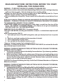 2
2
-
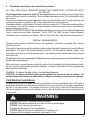 3
3
-
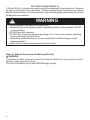 4
4
-
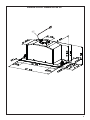 5
5
-
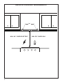 6
6
-
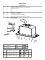 7
7
-
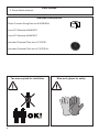 8
8
-
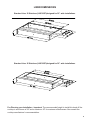 9
9
-
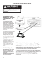 10
10
-
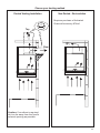 11
11
-
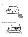 12
12
-
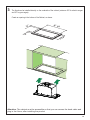 13
13
-
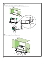 14
14
-
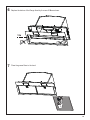 15
15
-
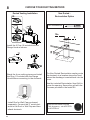 16
16
-
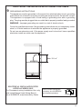 17
17
-
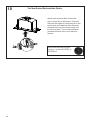 18
18
-
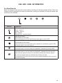 19
19
-
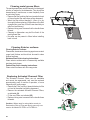 20
20
-
 21
21
-
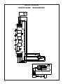 22
22
-
 23
23
-
 24
24
-
 25
25
-
 26
26
-
 27
27
-
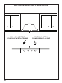 28
28
-
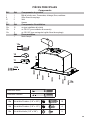 29
29
-
 30
30
-
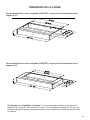 31
31
-
 32
32
-
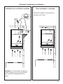 33
33
-
 34
34
-
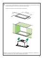 35
35
-
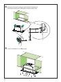 36
36
-
 37
37
-
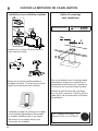 38
38
-
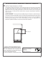 39
39
-
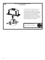 40
40
-
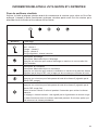 41
41
-
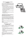 42
42
-
 43
43
-
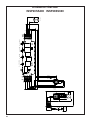 44
44
-
 45
45
-
 46
46
-
 47
47
-
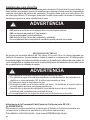 48
48
-
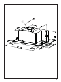 49
49
-
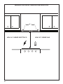 50
50
-
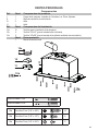 51
51
-
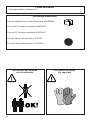 52
52
-
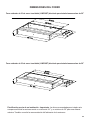 53
53
-
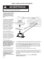 54
54
-
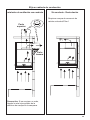 55
55
-
 56
56
-
 57
57
-
 58
58
-
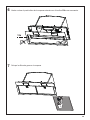 59
59
-
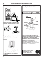 60
60
-
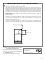 61
61
-
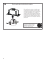 62
62
-
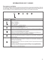 63
63
-
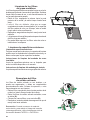 64
64
-
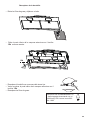 65
65
-
 66
66
-
 67
67
-
 68
68


Faber Inca Smart 28 Stainless Steel 240 El manual del propietario
- Categoría
- Campanas de cocina
- Tipo
- El manual del propietario
- Este manual también es adecuado para
en otros idiomas
Artículos relacionados
-
Faber Inca HC 29 SSV with VAM Guía de instalación
-
-
-
-
-
-
-
-
-