
1002 959 145 # metI
Model # 17898
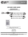
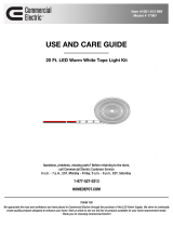
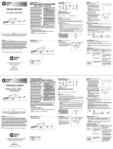
USE AND CARE GUIDE
12" RGBW LED Strip Kit (4-Pack)
Questions, problems, missing parts? Before returning to the store,
call Commercial Electric Customer Service
8 a.m. - 7 p.m., EST, Monday - Friday, 9 a.m. - 6 p.m., EST, Saturday
1-877-527-0313
HOMEDEPOT.COM
create quality products designed to enhance your home. Visit us online to see our full line of products available for your home
strive to continually
improvement needs.
Thank you for choosing Commercial Electric!
THANK YOU
R G B
WW
Flash
Strobe
Fade
Smooth
OFF ON
+12V
R
G
B
W
+12V
R
G
B
W
+12V
R
G
B
W
+12V
R
G
B
W
+12V
R
G
B
W
+12V
R
G
B
W
+1
2V
R
G
B
W
+12V
R
G
B
W

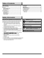
Table of Contents
Table of Contents .......................................................... 2
Safety Information ......................................................... 2
Warranty ......................................................................... 3
Three (3) Year Warranty..............................................................3
What is Covered .........................................................................3
What is Not Covered ...................................................................3
Pre-Installation ............................................................... 3
Planning Installation ...................................................................3
Tools Required.............................................................................3
Hardware Included ......................................................................3
Package Contents ........................................................................4
Installation.................................................................... 5
Care and Cleaning ........................................................9
Troubleshooting ............................................................9
FCC Statement................................................................9
Service Parts ................................................................ 10
Model Type .............................................................................. 10
Safety Information
Always keep the user manual within reach while installing this LED
tape. Please read and understand the user manual to ensure proper
installation and use. Always pay attention to the technical data shown
on the product. We reserve the right to make technical changes.
Fitting and maintenance work may only be carried out by a
professional or an electrician in accordance with local safety
regulations.
All electrical connections must have good contact in order for
this product to have a long, useful life.
The LED chips of this LED tape cannot be replaced.
This LED tape includes a linkable connector. Only link a maximum
of one LED tape. Do not link multiple tapes together.
Please only use the LED driver which has been provided with this
LED tape.
Never use the unit in a room where there is a danger of explosion
Do not bend, crush or pull the cable. Protect from sharp
edges, oil and heat.
Do not touch the LED strip or electrical connector directly
with hands.
For indoor use only.
Ensure the connectors are securely fastened before operating the tape.
Electrical waste should not be disposed of with household waste.
Please recycle where facilities exist.
IMPORTANT: Main power voltage and fuse must meet the
that the main cable is not live. Switch off the fuse.
NOTICE: LED lighting tape rating : 12V DC
2
CAUTION: Do not submerge any part of this unit.
Do not cut the LED tape.
WARNING:
Risk of electric shock. Mount the adaptor at a
height greater than 30 cm / 11.8 in. from the ground surface.
CAUTION: Danger of eye damage! Never look directly at
the LED chips of this LED tape.
Operation ...................................................................8
Maintenance...............................................................8

Warranty
WHAT IS NOT COVERED
lar
for any
consequential or incidental loss or damage, including but not limited to any labor/expense costs involved in the replacement or repair of
said product.
Contact the Customer Service Team at 1-877-527-0313 or visit www.HOMEDEPOT.COM.
3
THREE (3) YEAR WARRANTY
date of purchase.
This warranty applies only to the original consumer purchaser and only to products used in normal use and service. If this product is found to be
defective, the manufacturer’s only obligation, and your exclusive remedy, is the repair or replacement of the product at the manufacturer’s
or mishandling.
This warranty shall not apply to any product that is found to have been improperly installed, set-up, or used in any way not in accordance with the
instructions supplied with the product. This warranty shall not apply to a failure of the product as a result of an accident, misuse, abuse.
negligence, alteration, faulty installation, or any other failure not relating to faulty material or workmanship. This warranty shall not apply to the
WHAT IS COVERED
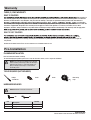
Pre-Installation
Read all instructions before installing.
To avoid damaging this product, place it on a soft, non-abrasive surface, such as carpet or cardboard.
:
Phillips
screwdriver
Pencil Brush
Measuring
tape
NOTE: Hardware not shown to actual size.
AA Screw 18
BB Clip (type MH1) 8
Personal injury and damage to the LED strip
and/or mounting surface may result if the LED strip is
pulled from the surface. To reduce the likelihood of
injury or damage, mount only on a surface that is
structurally sound.
AA BB
NOTE
Part
Description
Quantity
HARDWARE INCLUDED
TOOLS REQUIRED (NOT INCLUDED)
PLANNING INSTALLATION
HOMEDEPOT.COM
Please contact 1-877-527-0313 for further assistance.

4
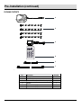
Pre-Installation (continued)
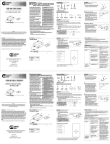
PACKAGE CONTENTS
A
B
C
F
E
D
Description
A Adaptor
B
C
D
Infrared receiver (Assembled to the adaptor (A))
Remote
4
1
1
1
Part
Quantity
12” LED strip
E
F
Connector wire (39”)
1
2
Connector wire (3.9”)
+12V
R
G
B
W
+12V
R
G
B
W
+12V
R
G
B
W
+12V
R
G
B
W
+12V
R
G
B
W
+12V
R
G
B
W
+12V
R
G
B
W
+12V
R
G
B
W
R G B
WW
Flash
Strobe
Fade
Smooth
OFF ON

5
Installation
1
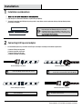
How will you run and conceal the wires to your LED tape lighting?
Temporarily mounting the LED light strip using painter’s tape allows you to experiment with tape light positioning before
permanent installation.
2
Installation considerations
Connecting LED tape and adaptor
IMPORTANT: Using painter’s tape or masking tape,
temporarily place the LED light strip into your desired
mounting position. Power on the LEDs to make sure you are
achieving the desired lighting effect before removing the 3M
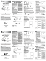
Connect connector to connector
HOMEDEPOT.COM
Please contact 1-877-527-0313 for further assistance.
NOTE: Connect connector to connector by aligning at
the arrows on the connectors.
NOTE: Connect connector to LED tape by aligning at the
arrow on the connector and the +12V on the LED tape
NOTE: Connect LED tape to LED tape by aligning at the
+12V on the LED tape.
NOTE: Connect LED tape to connector by aligning at the
+12V on the LED tape and the arrow on the connector.
Connect connector to LED tape
Connect LED tape to connector
Use the following four ways to connect the LED tape and adapter according to installation requirements.
Connect connector to LED tape
Connect LED tape to LED tape
Connect connector to connector
.
.
.
.
Connect LED tape to connector
Connect LED tape to LED tape
+12V
R
G
B
W
+12V
R
G
B
W
+12V
R
G
B
W
+12V
R
G
B
W

6
Installation (continued)
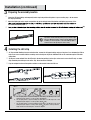
4
4A Tape method: Working from one end to the other, remove the 3M paper backing and press into place. Press between the LEDs to
help ensure secure contact with the mounting surface. Avoid pressing on the individual LEDs as this could damage the LED solder
connections.
4B Clip and screw method: Place the LED strip in the desired position. Use the clips and screws to secure the LED strip as shown.
Clips should be placed in open areas of the strip. Do not cover the LED lights.
Plug the adaptor into the wall receptacle and then use the remote to turn the LED's on.
Installing the LED strip
a.
b.
c.
a. Use an angle greater or equal to 90 degrees when there is an LED chip on the corner
while placing the strip in a concave position. (Angle 90 )
b. Use an angle greater or equal to 60 degrees when there is no LED chip on the corner
while placing the strip in a concave position. (Angle 60 )
c. Use an angle greater or equal to 60 degrees when there is an LED chip on the corner
while placing the strip in a convex position. (Angle 60 ) In the convex position the
angle should not reach 90 degrees. See above diagram.
Note :
LED Chip
Correct lncorrect lncorrect
Angle 90
o
Angle 60
o
4A 4B
3
Preparing the assembly location
Power the LED tape lighting and temporarily hold or tape into position with painter's tape or masking tape - do not remove
the 3M paper backing.
Adjust the lighting to various angles and positions to get the desired level of illumination and lighting appearance. If the
erly.
try a different mounting angle.
IMPORTANT: Before removing the 3M paper backing, it is
important to test the LED strip in the space you intend to light.
Once the 3M paper backing is removed and the lighting is fully
installed, you cannot reposition or move the LED tape light to
another location. The tape may not stick securely.

7
Installation (continued)
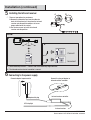
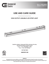
Installing the Infrared receiver
A
B
There are two options for you choose:
A: Remove the protective tape from the adhesive
back of infrared receiver, then place the infrared
receiver onto the position and press to insure
proper adhesion to the surface.
B: Use the two screws to install the infrared
receiver onto the position.
A:
Sensor efciency distance
≤
5 meters and sensor efciency angle about 60°.
The infrared receiver face to transmitter is correct.B:
A
B
Correct
Incorrect
Note:
5
+12V
R
G
B
W
+12V
R
G
B
W
5m
60°
3m 3m
R G B
WW
Flash
Strobe
Fade
Smooth
OFF ON
R
G B
WW
Flash
Strobe
Fade
Smooth
OFF
ON
R
G
B
WW
Flash
Strobe
Fade
Smooth
OFF ON
HOMEDEPOT.COM
Please contact 1-877-527-0313 for further assistance.
Connecting to the power supply
6
Connect adaptor to power outlet
Adaptor with plug
Infrared receiver controller
LED strip light
Infrared receiver
Connect the plug of adaptor to
infrared receiver controller

8
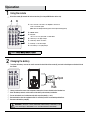
Push
Open
The remote contains a CR2025 DC 3V button battery. If swallowed, it could
cause severe injury or death within 2 hours. Seek medical attention immediately.
WARNING :
Maintenance
D
Always purchase the correct size and grade of battery that is most suitable for the intended use.
Clean the battery contacts and also those of the device prior to battery installation.
Ensure the batteries are installed correctly with regard to polarity (+ and -).
Remove batteries from the equipment when it is not being used for an extended period of time.
Remove used batteries promptly.
R G B
WW
Flash
Strobe
Fade
Smooth
OFF ON
Operation
1
Using the remote
2
Changing the battery
Direct the remote (D) towards the infrared receiver (C) to change RGBW colors of the strip.
To replace the battery, unscrew the small screw on the back side of the remote (D), and refer to the diagram on the back side of
the remote.
A--- Use to increase or decrease color brightness and to slow
down or accelerate speed.
B--- ON/OFF switch.
C--- R,G,B,W :
Choose color : red, green, blue or warm white.
D--- Flash key: 7 color jump change.
E--- Strobe key: Strobe color effect.
F--- Fade key: 7 color fade change.
G--- Smooth key: 3 color jump change.
NOTE:
(NOTE: there are 10 light intensity options and 10 speed setting options)
R G B
WW
Flash
Strobe
Fade
Smooth
OFF ON
A B
E
C
D
F
G
5

9
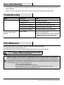
Care and Cleaning
Do not use any cleaners with chemicals, harsh abrasives, or solvents. Use only a dry soft cloth to dust or wipe carefully.
Troubleshooting
FCC Statement
The connector has faulty connections.
Check the connections of the connectors.
This device complies with part 15 of the FCC Rules. Operation is subject to the following two conditions:
(1) This device may not cause harmful interference, and
(2) this device must accept any interference received, including interference that may cause undesired operation.
CAUTION:
compliance could void the user’s authority to operate the equipment.
NOTE:
This equipment has been tested and found to comply with the limits for a Class B digital device, pursuant to part 15 of the FCC Rules.
These limits are designed to provide reasonable protection against harmful interference in a residential installation. This equipment generates,
uses and can radiate radio frequency energy and, if not installed and used in accordance with the instructions, may cause harmful interference
to radio communications. However, there is no guarantee that interference will not occur in a particular installation. If this equipment does cause
harmful interference to radio or television reception, which can be determined by turning the equipment off and on, the user is encouraged to try
to correct the interference by one or more of the following measures:
Reorient or relocate the receiving antenna.
Increase the separation between the equipment and receiver.
Connect the equipment into an outlet on a circuit different from that to which the receiver is connected.
Consult the dealer or an experienced radio/TV technician for help.
The LED will not light.
Problem
Possible Cause
Solution
The LED is burned out.
The power is off.
The power cord is not plugged in.
Discontinue use of the lamp.
Ensure the power supply is turned on.
Ensure the power cord is plugged into the outlet.
To clean the xture, disconnect the power by unplugging the adapter. Use a dry or slightly dampened, clean cloth to wipe the exterior
surface of the xture.
The circuit breaker is turned off.
Ensure the circuit breaker is in the “ON”
position.
The fuse blows or a circuit
breaker trips when the light is
turned on.
A wire is exposed.
Discontinue use of the lamp.
Unplug the unit from the
Contact a qualied electrician or call the Customer Care
wall.
Service 8 a.m. - 7 p.m., EST,
Monday - Friday, 9 a.m. - 6 p.m., EST, Saturday.
Team at 1-877-527-0313
HOMEDEPOT.COM
Please contact 1-877-527-0313 for further assistance.

10
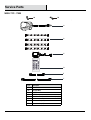
Service Parts
AA Screw
BB Clip (type MH1)
A
AA BB
MODEL TYPE : 17898
Part
Description
Adaptor
B
C
12” LED strip
D
E
F
Infrared receiver (Assembled to the adaptor (A))
Remote
Connector wire (39”)
Connector wire (3.9”)
A
C
F
E
D
B
+12V
R
G
B
W
+12V
R
G
B
W
+12V
R
G
B
W
+12V
R
G
B
W
+12V
R
G
B
W
+12V
R
G
B
W
+12V
R
G
B
W
+12V
R
G
B
W
R G B
WW
Flash
Strobe
Fade
Smooth
OFF ON

Questions, problems, missing parts? Before returning to the store,
call Commercial Electric Customer Service
8 a.m. - 7 p.m., EST, Monday - Friday, 9 a.m. - 6 p.m., EST, Saturday
1-877-527-0313
HOMEDEPOT.COM
Retain this manual for future use.

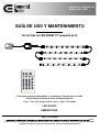
Artículo núm. 1002 959 145
Modelo núm. 17898
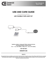
GUÍA DE USO Y MANTENIMIENTO
Kit de tiras de LED RGBW 12" (paquete de 4)
¿Tiene alguna pregunta o algún problema? ¿Le faltan piezas? Antes de volver a la tienda,
llame al Servicio de atención al cliente de Commercial Electric
8 a.m. - 7 p.m., EST, de lunes a viernes; 9 a.m. - 6 p.m., EST, sábados
1-877-527-0313
HOMEDEPOT.COM
zamos
continuamente por crear productos de calidad diseñados para realzar su hogar. Visítenos en línea para ver nuestra línea completa de productos
disponibles para todas las mejoras que su hogar necesita. ¡Gracias por elegir Commercial Electric!
GRACIAS POR TU COMPRA.
R G B
WW
Flash
Strobe
Fade
Smooth
OFF ON
+12V
R
G
B
W
+12V
R
G
B
W
+12V
R
G
B
W
+12V
R
G
B
W
+12V
R
G
B
W
+12V
R
G
B
W
+1
2V
R
G
B
W
+12V
R
G
B
W

Tabla de contenidos
Tabla de contenidos....................................................... 2
Información de seguridad.............................................. 2
Garantía........................................................................... 3
Garantía de tres (3) años.............................................................. 3
¿Qué cubre?................................................................................. 3
¿Qué no cubre?............................................................................ 3
Preinstalación................................................................. 3
Herramientas necesarias............................................................. 3
Tornillería incluida....................................................................... 3
Contenidos del paquete............................................................... 4
Instalación..................................................................... 5
Funcionamiento.............................................................8
Mantenimiento.............................................................. 8
Mantenimiento y limpieza............................................ 9
Reparación de averías.................................................. 9
Declaración de cumplimiento de la FCC (Comisión
Federal de Comunicaciones)................................... 9
Piezas de repuesto..................................................... 10
Tipo de Modelo.......................................................................... 10
Información de seguridad
Tenga siempre a mano el manual del usuario mientras instala esta
cinta de LED. Lea y comprenda el manual del usuario para asegurar
una instalación y uso correctos. Siempre preste atención a los datos
técnicos indicados en el producto. Nos reservamos el derecho de
Los trabajos de montaje y mantenimiento solo podrán ser
acuerdo con las normas de seguridad locales.
Para que este producto tenga una larga vida útil, todas las
conexiones eléctricas deben hacer buen contacto.
Los chips LED de esta cinta de LED no pueden reemplazarse.
Esta cinta de LED incluye un conector acoplable. No conecte más
de una cinta de LED. No conecte múltiples cintas.
Utilice solamente el controlador LED que se suministra con esta
cinta de LED.
Nunca utilice la unidad en una habitación donde exista peligro de
No doble, aplaste ni tire del cable. Manténgalo alejado de bordes
No toque la tira de LED ni ningún conector eléctrico directamente
con las manos.
Solo para uso en interior.
utilizar la cinta.
Los residuos eléctricos no deben desecharse junto con los residuos
domésticos. Recicle en las instalaciones correspondientes.
IMPORTANTE: La tensión de la alimentación principal y el
técnicos. Antes de comenzar a trabajar, asegúrese de que el
cable principal no tiene tensión.
AVISO: Potencia de la cinta de iluminación LED: 12 V CC
2
PRECAUCIÓN: No sumerja ninguna parte de esta unidad.
No corte la cinta de LED.
ADVERTENCIA: Riesgo de descargas eléctricas. Instale el
adaptador a una altura de más de 30 cm/11,8 pulgadas de
PRECAUCIÓN: Peligro de lesiones oculares. Nunca mire
directamente a los chips LED de la cinta de LED.

Garantía
¿QUÉ NO CUBRE?
El fabricante no otorga y renuncia expresamente a cualquier garantía, ya sea explícita o implícita, de idoneidad para un n determinado, distinta
de la garantía que incluye este producto. El fabricante renuncia expresamente a cualquier responsabilidad y no se hará responsable de ninguna
pérdida ni daño consiguientes o imprevistos, incluidos pero sin limitarse a, los costes de mano de obra o los gastos derivados de la sustitución
o la reparación de dicho producto.
Póngase en contacto con el equipo del Servicio de atención al cliente llamando al 1-877-527-0313 o visite www.HOMEDEPOT.COM.
3
GARANTÍA DE TRES (3) AÑOS
El fabricante garantiza que esta lámpara no presentará defectos de material ni de mano de obra durante un período de tres (3) años a partir de
la fecha de compra. Esta garantía se aplica solo al comprador original y únicamente a los productos que se utilicen en condiciones normales y
reciban un mantenimiento adecuado. Si este producto resulta defectuoso, la única obligación del fabricante, y la única solución, es reparar o
sustituir el producto a discreción del fabricante, siempre que el producto no se haya dañado por uso indebido, abuso, accidente, modicaciones,
alteración, negligencia o mal manejo. Esta garantía no se aplicará a ningún producto que se haya instalado, congurado o utilizado de forma
incorrecta sin haber seguido las instrucciones que incluye el producto. Esta garantía no se aplicará a ningún fallo del producto ocasionado por
accidentes, mal uso, abuso, negligencia, alteración, instalación defectuosa o cualquier otro fallo que no esté relacionado con el material
defectuoso ni la mano de obra. Esta garantía no se aplicará al acabado de ninguna parte del producto, como la supercie y/o partes erosionadas,
ya que se considera uso y desgaste normal.
¿QUÉ CUBRE?
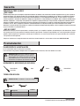
Preinstalación
Lea las instrucciones antes de comenzar la instalación.
Para evitar dañar este producto, colóquelo sobre una supercie suave, no abrasiva, como una alfombra o un cartón.
Destornillador
de estrella
Lápiz Brocha
Cinta métrica
OBSERVACIÓN: La tornillería no se muestra en tamaño real.
AA Tornillo 18
BB Enganche (tipo MH1) 8
AA BB
OBSERVACIÓN: Retirar la tira de LED de la supercie
de montaje podría producir lesiones, así como daños en
la tira de LED y/o en la supercie de montaje. Para reducir
la probabilidad de lesiones o daños, lleve a cabo el montaje
únicamente en una supercie cuya estructura sea sólida.
Pieza
Descripción
Cantidad
TORNILLERÍA INCLUIDA
HERRAMIENTAS NECESARIAS (NO INCLUIDAS)
PLANIFICACIÓN DE LA INSTALACIÓN
HOMEDEPOT.COM
Por favor, llame al 1-877-527-0313 para más información.

4
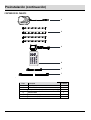
Preinstalación (continuación)
CONTENIDOS DEL PAQUETE
A
B
C
F
E
D
Descripción
A Adaptador
B
C
D
Receptor de infrarrojos (instalado en el adaptador [A])
Control remoto
4
1
1
1
Pieza
Cantidad
Tira de LED 12”
E
F
Cable conector (39”)
1
2
Cable conector (3,9”)
+12V
R
G
B
W
+12V
R
G
B
W
+12V
R
G
B
W
+12V
R
G
B
W
+12V
R
G
B
W
+12V
R
G
B
W
+12V
R
G
B
W
+12V
R
G
B
W
R G B
WW
Flash
Strobe
Fade
Smooth
OFF ON

5
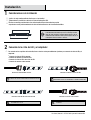
Instalación
1
¿Cuál es la mejor conguración de diseño para su instalación?
¿Cómo colocará y ocultará los cables de la cinta de iluminación LED?
Realizar un montaje provisional de la tira de iluminación LED con cinta adhesiva permite
experimentar con el posicionamiento de la cinta de iluminación antes de la instalación denitiva.
2
Consideraciones de instalación
Conexión de la cinta de LED y el adaptador
IMPORTANTE: Con cinta adhesiva, coloque provisionalmente
la tira de iluminación LED en la posición de montaje deseada.
Antes de retirar el papel de respaldo 3M para llevar a cabo la
instalación nal, encienda los ledes para asegurarse de que se
está logrando el efecto luminoso deseado.
Conectar el conector a otro conector
HOMEDEPOT.COM
Por favor, llame al 1-877-527-0313 para más información.
OBSERVACIÓN: Conecte ambos conectores alineando
sus echas.
OBSERVACIÓN: Conecte el conector a la cinta de LED alineando
la echa del conector con el indicador de +12 V de la cinta de LED.
OBSERVACIÓN: Conecte las cintas de LED alineando
sus indicadores de +12 V.
Conectar el conector a la cinta de LED
Conectar la cinta de LED al conector
De acuerdo con los requisitos de instalación, lleve a cabo los cuatro procedimientos siguientes para conectar la cinta de LED y el
adaptador.
Conectar el conector a la cinta de LED
Conectar la cinta de LED a otra cinta de LED
Conectar el conector a otro conector
.
.
.
.
Conectar la cinta de LED al conector
Conectar la cinta de LED a otra cinta de LED
+12V
R
G
B
W
+12V
R
G
B
W
+12V
R
G
B
W
+12V
R
G
B
W
OBSERVACIÓN: Conecte la cinta de LED al conector alineando
el indicador de +12 V de la cinta de LED con la echa del conector.

6
Instalación (continuación)
4
4A Método de jación con cinta: trabajando de un extremo al otro, retire el papel de respaldo 3M y presione para jar en la posición
adecuada. Presione el espacio entre los ledes para asegurar un contacto rme con la supercie de montaje. Evite presionar los ledes
de forma individual, ya que esto podría dañar las conexiones de soldadura de LED.
4B Método de enganche y tornillo: coloque la tira de LED en la posición deseada. Utilice los enganches y tornillos para asegurar la tira
de LED tal y como se muestra. Los enganches deben colocarse en áreas abiertas de la tira. No cubra las luces de LED.
Conecte el adaptador al receptáculo de pared y, a continuación, utilice el control remoto para encender el LED.
Instalación de la tira de LED
a.
b.
c.
a. En posición cóncava, coloque la tira en un ángulo mayor que o igual a 90 grados
cuando haya un chip LED en la esquina de esta. (Ángulo de ≥ 90
)
b. En posición cóncava, coloque la tira en un ángulo mayor que o igual a 60 grados
cuando no haya un chip LED en la esquina de esta. (Ángulo de ≥ 60 )
c. En posición convexa, coloque la tira en un ángulo mayor que o igual a 60 grados
cuando haya un chip LED en la esquina de esta. (Ángulo de ≥ 60 ) En posición
convexa, el ángulo no debe alcanzar los 90 grados. Consulte el diagrama de arriba.
Observación:
Chip LED
Correcto lncorrecto lncorrecto
Ángulo de 90
o
Ángulo de 60
o
4A 4B
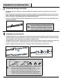
3
Preparación del lugar de montaje
Encienda la cinta de LED y sujétela por un momento o colóquela en la posición deseada con cinta adhesiva. No retire el papel de
respaldo 3M.
Ajuste la iluminación en varios ángulos y posiciones para obtener la apariencia y el nivel de iluminación que desee. Si los ledes crean
reejos o puntos de luz no deseados en las paredes, cambie la posición de la tira de iluminación de la cinta, de manera que esté más
lejos de las supercies. También puede probar con un ángulo de montaje diferente.
Una vez que haya determinado la posición nal de montaje, limpie la supercie para asegurarse de que el respaldo autoadhesivo 3M
se adhiera correctamente.
IMPORTANTE: Antes de retirar el papel de respaldo 3M, es
importante probar la tira de LED en el lugar que desea iluminar.
Una vez que se haya retirado el papel de respaldo 3M y la
iluminación esté completamente instalada, no podrá cambiar
la posición de la cinta de LED ni trasladarla a otro lugar. De
hacerlo, es posible que la cinta no se adhiera de forma segura.

7
Instalación (continuación)
Instalación del receptor de infrarrojos
A
B
Puede elegir entre dos opciones:
A: Retire la cinta protectora de la parte trasera adhesiva
del receptor de infrarrojos y, a continuación, coloque
el receptor de infrarrojos en la posición deseada y
presione para asegurarse de que se ha adherido
correctamente a la supercie.
B: Utilice los dos tornillos para instalar el receptor de
infrarrojos en la posición deseada.
A: Distancia de eciencia del sensor ≤5 metros y ángulo de eciencia del sensor de aprox. 60°.
B: La instalación del receptor de infrarrojos de cara al transmisor es la correcta.
A
B
Correcto
Incorrecto
Observación:
5
+12V
R
G
B
W
+12V
R
G
B
W
5m
60°
3m 3m
R G B
WW
Flash
Strobe
Fade
Smooth
OFF ON
R
G
B
WW
Flash
Strobe
Fade
Smooth
OFF
ON
R
G
B
WW
Flash
Strobe
Fade
Smooth
OFF
ON
HOMEDEPOT.COM
Por favor, llame al 1-877-527-0313 para más información.
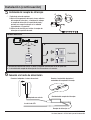
Conexión a la fuente de alimentación
6
Conecte el adaptador a la toma de corriente
Adaptador con enchufe
Controlador del receptor de infrarrojos
Luz de tira de LED
Receptor de infrarrojos
Conecte el enchufe del adaptador al
controlador del receptor de infrarrojos

8
Empujar
Abrir
ADVERTENCIA: El control remoto contiene una pila de botón CR2025 de 3 V CC. Si se ingiere, puede
ocasionar lesiones graves o la muerte en un lapso de 2 horas. Busque atención médica inmediatamente.
Maintenance
D
Adquiera siempre pilas del tamaño y el grado más adecuado para el uso previsto.
Limpie los contactos de las pilas y los del dispositivo antes de instalar las pilas.
Asegúrese de que las pilas estén instaladas correctamente de acuerdo a la polaridad (+ y -).
Retire las pilas del equipo si este no se usa por un largo período de tiempo.
Retire inmediatamente las pilas usadas.
R G B
WW
Flash
Strobe
Fade
Smooth
OFF ON
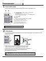
Funcionamiento
1
Uso del control remoto
2
Cambio de pilas
Apunte el control remoto (D) hacia el receptor de infrarrojos (C) para cambiar los colores RGBW de la tira.
Para cambiar la pila, desatornille el tornillo pequeño en la parte trasera del control remoto (D) y consulte el diagrama en la parte
trasera del control remoto.
A--- Se utiliza para aumentar o disminuir el brillo del color y para reducir
o acelerar la velocidad.
B--- Interruptor ON/OFF.
C--- R,G,B,W :
Elija el color: rojo (R), verde (G), azul (B) o blanco cálido (WW).
D--- Botón Flash: cambio rápido de 7 colores.
E--- Botón Strobe: efecto estroboscópico de color
F--- Botón Fade: cambio gradual de 7 colores.
G--- Botón Smooth: cambio rápido de 3 colores.
OBSERVACIÓN: distancia de eciencia del sensor ≤5 metros.
(OBSERVACIÓN: puede elegir entre 10 opciones de intensidad de la luz y 10
opciones de conguración de velocidad)
R G B
WW
Flash
Strobe
Fade
Smooth
OFF ON
A B
E
C
D
F
G

9
Mantenimiento y limpieza
No emplee productos de limpieza que contengan químicos, abrasivos fuertes ni disolventes. Utilice únicamente un paño seco para
quitar el polvo o limpiar con cuidado.
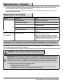
Reparación de averías
Declaración de cumplimiento de la FCC (Comisión Federal de Comunicaciones)
El conector presenta conexiones defectuosas.
Inspeccione las conexiones de los conectores.
Este aparato cumple con la sección 15 de las normas de la FCC. El funcionamiento depende de las dos condiciones siguientes:
(1) Este aparato no puede provocar interferencias perjudiciales, y
(2) este aparato debe aceptar todas las interferencias recibidas, incluidas las interferencias que puedan provocar un funcionamiento no deseado.
PRECAUCIÓN: Los cambios o modicaciones no aprobadas expresamente por la parte responsable
del cumplimiento podrían anular la autoridad del usuario para poner en funcionamiento este equipo.
OBSERVACIÓN: Las pruebas efectuadas en este equipo han servido para determinar que cumple los límites exigidos para los dispositivos
digitales de Clase B, especicados en la parte 15 de las normas de la FCC. Dichos límites se han establecido con el n de conceder un margen
razonable de protección contra interferencias perjudiciales en caso de instalación en áreas residenciales. Este equipo genera, utiliza y puede
irradiar energía de radiofrecuencia y, si no se instala y utiliza de acuerdo con las instrucciones, puede provocar interferencias perjudiciales en
las radiocomunicaciones. No obstante, no se garantiza que no se producirán interferencias en una instalación determinada. Si este equipo
provoca interferencias en la recepción radiofónica o televisiva, lo que puede determinarse encendiendo y apagando el equipo, se recomienda al
usuario que trate de corregirlas tomando una o más de las siguientes medidas:
Cambiar la orientación o ubicación de la antena receptora.
Aumentar la separación entre el equipo y el receptor.
Conectar el equipo en una toma de corriente que pertenezca a un circuito distinto de aquel en el que está conectado el receptor.
Consultar al distribuidor o a un técnico experto en radio y televisión para obtener ayuda.
El LED no se enciende.
Problema
Posible causa
Solución
El LED está quemado.
La alimentación está apagada.
El cable de alimentación no está conectado.
Interrumpa el uso de la lámpara.
Asegúrese de que la fuente de alimentación está encendida.
Asegúrese de que el cable de alimentación esté conectado
a la toma de corriente.
Para limpiar el dispositivo de iluminación, desconecte la alimentación desenchufando el adaptador. Utilice un paño suave seco o
ligeramente mojado para limpiar la supercie exterior del dispositivo.
El disyuntor está apagado.
Asegúrese de que el disyuntor está en la posición de
encendido.
El fusible se quema o se
activa el disyuntor cuando
se enciende la luz.
Hay un cable expuesto.
Interrumpa el uso de la lámpara.
Desenchufe la unidad de la pared.
Póngase en contacto con un electricista cualicado o
llame al 1-877-527-0313 para contactar con el equipo
del Servicio de atención al cliente de 8 a.m. - 7 p.m., EST,
de lunes a viernes; 9 a.m. - 6 p.m., EST, sábados.
HOMEDEPOT.COM
Por favor, llame al 1-877-527-0313 para más información.

10
Piezas de repuesto
AA Tornillo
BB Enganche (tipo MH1)
A
AA BB
TIPO DE MODELO: 17898
Pieza
Descripción
Adaptador
B
C
Tira de LED 12”
D
E
F
Receptor de infrarrojos (instalado en el adaptador [A])
Control remoto
Cable conector (39”)
Cable conector (3,9”)
A
C
F
E
D
B
+12V
R
G
B
W
+12V
R
G
B
W
+12V
R
G
B
W
+12V
R
G
B
W
+12V
R
G
B
W
+12V
R
G
B
W
+12V
R
G
B
W
+12V
R
G
B
W
R G B
WW
Flash
Strobe
Fade
Smooth
OFF ON

¿Tiene alguna pregunta o algún problema? ¿Le faltan piezas? Antes de volver a la tienda,
llame al Servicio de atención al cliente de Commercial Electric
8 a.m. - 7 p.m., EST, de lunes a viernes; 9 a.m. - 6 p.m., EST, sábados
1-877-527-0313
HOMEDEPOT.COM
Conserve este manual para futuras consultas.
-
 1
1
-
 2
2
-
 3
3
-
 4
4
-
 5
5
-
 6
6
-
 7
7
-
 8
8
-
 9
9
-
 10
10
-
 11
11
-
 12
12
-
 13
13
-
 14
14
-
 15
15
-
 16
16
-
 17
17
-
 18
18
-
 19
19
-
 20
20
-
 21
21
-
 22
22


Commercial Electric 1002 959 145 Instrucciones de operación
- Tipo
- Instrucciones de operación
- Este manual también es adecuado para
En otros idiomas
Documentos relacionados
-
 Commercial Electric DC5237WH-A Manual de usuario
-
 Commercial Electric 17067 Instrucciones de operación
-
 Commercial Electric 16508 Guía de instalación
-
 Commercial Electric DC5184WH-A Guía del usuario
-
 Commercial Electric DC5185WH-A Manual de usuario
-
 Commercial Electric DC9521WH-A Manual de usuario
-
 Commercial Electric 54581141 Instrucciones de operación
-
 Commercial Electric 54259141 Guía de instalación


