LG DLE1310W El manual del propietario
- Categoría
- Secadoras
- Tipo
- El manual del propietario
Este manual también es adecuado para

To contact LG Electronics, 24 hours a day,
7 days a week:
1=800=243=0000
Or visit us on the Web at: us.lge.com
DRYERS
USER'SGUIDE&
INSTA//MIONINSTRUCTIONS
Before beginning installation, read these
instructions carefully. This wll simplify installation
and ensure that the dryer is installed correctly and
safely. Leave these instructions near the dryer
after installation for future reference.
Pour contacter LG Electronics, 24 heures
par jour, 7 jours par semaine
1-800-243-0000
ou visitez notre site Web a I'adresse
us.lge.com
SECADORAS
GUIADE[ USUARIOE
INSTRUCCIONESDEINSTA/ACION
Antes de comenzar [a JnstalacJ6n, lea atentamente
estas instrucciones. Esto simplificara [a instalaciOn
y asegurara que [a secadora esta instalada
en forma correcta Y segura. Conserve estas
instrucciones cerca de [a secadora [uego de [a
instalaciOn para futuras consultas.
Models/Modelos
Electric/Electrica Cas/Cas
DLE1310W DLG1320W
P/No. 3828EL3004L

INTP,ODUCflON
IMPORTANT SAFETY INSTRUCTIONS
Basic Safety Precautions ....................................... 3
What to Do if You Smell Gas .................................. 4
Grounding Instructions ........................................... 5
Safety Instructions for Installation ...................... 5, 6
Safety Instructions for Connecting Electricity ....... 7
PARTS AND FEATURES
Key Parts and Components ................................... 8
INSTALLATION INSTRUCTIONS
Choose the Proper Location .................................. 9
Clearances ............................................................. 9
Installation With Optional
Pedestal Base or Stacking Kit.............................. 10
Leveling the Dryer ................................................ 11
Reversing the Door Swing .................................... 11
Changing the Dryer Vent Location ....................... 12
Venting the Dryer ............................................ 13, 14
Connecting Gas Dryers .................................. 15, 16
Connecting Electric Dryers .............................. 17-21
Special Requirements for Manufactured
or Mobile Homes .................................................. 22
Final Installation Check ....................................... 22
HOW TO USE
Sorting Loads ....................................................... 23
Loading the Dryer ................................................. 23
Check the Lint Filter Before Every Load ............... 23
Control Panel Features ......................................... 24
Cycle Guide .......................................................... 25
Operating the Dryer .............................................. 26
Cycle Setting Buttons .......................................... 27
Cycle Option Buttons .......................................... 28
USER-MAINTENANCE INSTRUCTIONS
Regular Cleaning .................................................. 29
TROUBLESHOOTING
Before Calling for Service ................................ 30.31
SPECIFICATIONS/OPTIONAL
ACCESSORIES
Key Dimensions and Specifications ..................... 32
Optional Accessories ........................................... 32
Pedestal Installation ....................................... 33, 34
Stacking Kit Installation .................................. 35, 36
WARRANTY ...................................................37
f_
THANKYOU
Congratulations on your purchase
and welcome to the LG family. Your
new LG Dryer combines the most
advanced drying sensor technology
with simple operation and high
efficiency. By following the
operating and care instructions
in this manual, your dryer will
provide you with many years of
reliable service.
Product Registration Information
Model:
Serial Number:
Date of Purchase:
The model and serial number can be located on the rating
plate inside the front door.
2

IMPORTANTSAFETYiNSTRUCTiONS
READ ALL iNSTRUCTiONS BSFORE USE
WARNING For your safety,the information in this manual must be
followed to minimize the risk of fire or explosion, electric shock, or to prevent
property damage, personal injury, or loss of life.
Your Safety and the safety of others is very important.
We have provided many important safety messages in this manual and on your appliance. Always read
and obey all safety messages.
This isthe safety alert symbol.
This symbol alerts you to potential hazards that can kill or hurt you and others.
All safety messages will follow the safety alert symbol and either the word DANGER or WARNING.
These words mean:
_DANGER: You can be killed or seriously injured if you don't immediately follow instructions.
_WARN|_G: You can be killed or seriously injured ifyou don't follow instructions.
All safety messages will tell you what the potential hazard is, tell you how to reduce the chance of
injury, and tell you what can happen if the instructions are not followed.
BASIC SAFETY PRECAUTIONS
WARNING=
appliance, follow basic precautions, including the following:
• Read all instructions before using the dryer.
Before use, the dryer must be properly installed
as described in this manual.
Do not place items exposed to cooking oils in
your dryer. Items contaminated with cooking
oils may contribute to a chemical reaction that
could cause a load to catch fire.
Do not dry articles that have been previously
cleaned in, washed in, soaked in, or spotted
with gasoline, dry-cleaning solvents, or other
flammable or explosive substances as they give
off vapors that could ignite or explode.
• Do not reach intothe dryer if the drum or any
other part is moving.
Do not repair or replace any part of the dryer
or attempt any servicing unless specifically
recommended in this Use and Care Guide or
in published user-repair instructions that you
understand and have the skills to carry out.
• Do not tamper with controls.
Before the dryer is removed from service or
discarded, remove the door to the drying
compartment.
To reduce the risk of fire, electric shock, or injury to persons when using this
Do not allow children to play on or in the dryer.
Close supervision of children is necessary when
the dryer is used near children.
Do not use fabric softeners or products to
eliminate static unless recommended by the
manufacturer of the fabric softener or product.
Do not use heat to dry articles containing
foam rubber or similarly textured rubber-like
materials.
Keep area around the exhaust opening and
adjacent surrounding areas free from the
accumulation of lint, dust, and dirt.
The interior of the dryer and exhaust vent
should be cleaned periodically by qualified
service personnel.
Do not install or store the dryer where it will be
exposed to the weather.
Always check the inside of the dryer for foreign
objects.
Clean lint screen before or after each load.
5

I PORTANTSAFETYiNSTRUcTiONS
R_:AD ALL iNSTRUCTiONS BSFORS USS
_WARNING For your safety,the information in this manual must be
followed to minimize the risk of fire or explosion, electric shock, or to prevent
property damage, personal injury, or loss of life.
• Do not store or use gasoline or other
flammable vapors and liquids in the
vicinity of this appliance or any other
appliances.
• installation and service must be
performed by a qualified installer,
service agency, or the gas supplier.
WHAT TO DO IF YOU SMELL GAS:
1. Do not try to light a match or cigarette,
or turn on any gas or electrical
appliance.
2. Do not touch any electrical switches.
Do not use any phone in your building.
3. Clear the room, building, or area of all
occupants.
4. Immediately call your gas supplier
from a neighbor's phone. Follow the
gas supplier's instructions carefully.
5. if you cannot reach your gas
supplier, call the fire department.
CALiFORNiA SAFE DRINKING WATER AND TOXIC ENFORCEMENT ACT
This act requires the governor of California to publish a list of substances known to the state to cause
cancer, birth defects, or other reproductive harm and requires businesses to warn customers of potential
exposure to such substances.
Gas appliances can cause minor exposure to four of these substances, namely benzene, carbon monoxide,
formaldehyde, and soot, caused primarily by the incomplete combustion of natural gas or LP fuels.
Properly adjusted dryers will minimize incomplete combustion. Exposure to these substances can be
minimized further by properly venting the dryer to the outdoors.
4

I PORTANTSAFETYINSTRUCTIONS
READ ALL iNSTRUCTiONS BSFORE USE
WARNING For your safety,the information in this manual must be
followed to minimize the risk of fire or explosion, electric shock, or to prevent
property damage, personal injury, or loss of life.
GROUNDING iNSTRUCTiONS
This appliance must be grounded. In the event
of malfunction or breakdown, grounding will
reduce the risk of electric shock by providing
a path of least resistance for electric current.
This appliance must be equipped with a cord
having an equipment-grounding conductor and
a grounding plug. The plug must be plugged into
an appropriate outlet that is properly installed and
grounded in accordance with all local codes and
ordinances.
WARNING
improper connection of the equipment=
grounding conductor can result in a risk of
electric shock. Check with a qualified electrician
or service person ifyou are in doubt as to whether
the appliance is properly grounded.
Do not modify the plug provided with the
appliance. If it will not fit the outlet, have a proper
outlet installed by a qualified electrician.
This appliance must be connected to a grounded
metal, permanent wiring system or an equipment-
grounding conductor must be run with the circuit
conductors and connected to the equipment-
grounding terminal or lead on the appliance.
Electrical shock can result if the dryer is not
properly grounded.
SAFETY INSTRUCTIONS FOR INSTALLATION
WARNING: To reduce the risk of fire, electric shock, or injury to persons when using this
appliance, follow basic precautions, including the following:
• Properly ground dryer to conform with all
governing codes and ordinances. Follow
details in the installation instructions. Electrical
shock can result if the dryer is not properly
grounded.
• Before use, the dryer must be properly
installed as described in this manual.
Electrical shock can result if the dryer is not
properly grounded.
, install and store the dryer where it will not be
exposed to temperatures below freezing or
exposed to the weather.
• All repairs and servicing must be performed
by an authorized servicer unless specifically
recommended in this Owner's Guide. Use
only authorized factory parts. Failure to follow
this warning can cause serious injury, fire,
electrical shock or death.
, To reduce the risk of electric shock, do not
install the dryer in humid spaces. Failure to
follow this warning can cause serious injury, fire,
electrical shock, or death.
• Oonnect to a properly rated, protected,
and sized power circuit to avoid electrical
overload, improper power circuit can melt,
creating electrical shock and/or fire hazard.
Remove all packing items and dispose of all
shipping materials properly. Failure to do so
can result in death, explosion, fire, or burns.
Place dryer at least 18 in. above the floor
for a garage installation. Failure to do so can
result in death, explosion, fire, or burns.
Keep all packaging from children. Packaging
material can be dangerous for children. There is
a risk of suffocation.
5

I PORTANTSAFETYiNSTRUcTiONS
R :AD ALL iNSTRUCTiONS BI=FORI: USS
WARNING For your safety,the information in this manual must be
followed to minimize the risk of fire or explosion, electric shock, or to prevent
property damage, personal injury, or loss of life.
SAFETY iNSTRUCTiONS FOR iNSTALLATiON
Exhaust/Ducting:
• Gas dryers MUST be exhausted to the
outside. Failure to follow these instructions
can result in fire or death.
• The dryer exhaust system must be exhausted
to the outside of the dwelling, if the dryer is
not exhausted outdoors, some fine lint and
large amounts of moisture will be expelled
into the laundry area. An accumulation of
lint in any area of the home can create a health
and fire hazard.
• Use only rigid metal or flexible metal 4=in.
diameter ductwork inside the dryer cabinet
or for exhausting to the outside. Use of
plastic or other combustible ductwork can
cause a fire. Punctured ductwork can cause
a fire if itcollapses or becomes otherwise
restricted in use or during installation.
• Ductwork is not provided with the dryer, and
you should obtain the necessary ductwork
locally. The end cap should have hinged
dampers to prevent backdraft when the dryer
is not in use. Failure to follow these instructions
can result in fire or death.
• The exhaust duct must be 4 in. (10 cm) in
diameter with no obstructions. The exhaust
duct should be kept as short as possible.
Make sure to clean any old ducts before
installing your new dryer. Failure to follow
these instructions can result in fire or death.
• Rigid or semi rigid metal ducting is
recommended for use between the
dryer and the wall. in special installations
when it is impossible to make a connection
with the above recommendations, a UL-
listed flexible metal transition duct may be
used between the dryer and wall connection
only. The use of this ducting will affect drying
time. Failure to follow these instructions can
result in fire or death.
• DO NOT use sheet metal screws or other
fasteners which extend into the duct that
could catch lint and reduce the efficiency
of the exhaust system. Secure all joints with
duct tape. For complete details, follow the
installation Instructions. Failure to follow these
instructions can result in fire or death.
6

I PORTANTSAFETYINSTRUCTIONS
READ ALL INSTRUCTIONS BEFORE USE
WARNING For your safety,the information in this manual must be
followed to minimize the risk of fire or explosion, electric shock, or to prevent
property damage, personal injury, or loss of life.
SAFETY iNSTRUCTiONS FOR CONNECTING ELECTRiCiTY
WARNING: To reduce the risk of fire, electric shock, or injury to persons when using this
appliance, follow basic precautions, including the following:
, Do not, under any circumstances, cut or
remove the ground prong from the power
cord. To prevent personal injury or damage to
the dryer, the electrical power cord must be
plugged into a properly grounded outlet.
, For personal safety, this dryer must be
properly grounded. Failure to do so can result
in electrical shock or injury.
• Refer to the installation instructions in this
manual for specific electrical requirements
for your model. Failure to follow these
instructions can create an electrical shock
hazard and/or a fire hazard.
• This dryer must be plugged into a properly
grounded outlet. Electrical shock can result if
the dryer is not properly grounded. Have the
wall outlet and circuit checked by a qualified
electrician to make sure the outlet is properly
grounded. Failure to follow these instructions
can create an electrical shock hazard and/or a
fire hazard.
• The dryer should always be plugged into
its own individual electrical outlet which
has a voltage rating that matches the rating
plate. This provides the best performance
and also prevents overloading house wiring
circuits which could cause a fire hazard from
overheated wires.
, Never unplug your dryer by pulling on the
power cord. Always grip plug firmly and pull
straight out from the outlet. The power cord
can be damaged, resulting in a risk of fire and
electrical shock.
• Repair or replace immediately all power
cords that have become frayed or otherwise
damaged. Do not use a cord that shows
cracks or abrasion damage along its length
or at either end. The power cord can melt,
creating electrical shock and/or fire hazard.
• When installing or moving the dryer, be
careful not to pinch, crush, or damage
the power cord. This will prevent injury and
prevent damage to the dryer from fire and
electrical shock.
SAVE THESE INSTRUCTIONS
7

PARTSANDFEATU ES
KEY PARTSAND COMPONENTS
O
O
EASY-TO-USE CONTROL PANEL
Rotate the Cycle Selector Knob to select the
desired dry cycle. Add cycle options or adjust
settings with the touch of a button.
LED DISPLAY
The easy-to-read LED display shows cycle
options and information and provides status
messages during operation.
O
EASY-ACCESS REVERSIBLE DOOR
Wide-opening door provides easy access for
loading and unloading. Door swing can be
reversed to adjust for installation location.
O
FRONT-MOUNT LiNT FILTER
Front-mounted lintfilter allows for easy access
and cleaning after every load.
O
LEVELING FEET
Four leveling feet (two in the front, and two in
the back) adjust to improve dryer stability on
uneven floors.
Q
I......_....._
O(_OkOOS _
\,
\\
Power Cord Location
(Gas Models)
Terminal Block
Access Panel
(Electric Models)
Gas /
Connection
Location
(Gas Models)
Exhaust Duct
Outlet
Rear of Dryer
8

INSTALLATIONINSTRUCTIONS
iMPORTANT: Read all installation instructions completely before
installing and operating your dryer!
it is important that you review this entire manual before installing and using your dryer. Detailed instructions
concerning electrical connections, gas connections, and exhaust requirements are provided on the
following pages.
CHOOSE THE PROPER LOCATION
• Store and install the dryer where it will not be
exposed to temperatures below freezing or
exposed to outdoor weather conditions.
• Choose a location with a solid, level floor.
• if the dryer is being installed in a garage,
place the dryer at least 18 in. (46 cm) above
the floor.
• Properly ground dryer to conform with all
governing codes and ordinances.
• To reduce the risk of electric shock, do not
install the dryer in damp or wet locations.
• if you are installing your dryer in a manufactured
or mobile home, please refer to the section
Special Requirements for Manufactured or
Mobile Homes.
CLEARANCES
20"_
(50.8 cm)
0
(45.72 cm)_
| ' , , ,
4"_,q1_,_30"_ 1_4"
(10 cm) (76.1 cm) (10 cm)
50"_
(127 cm)
1"-_1I-_ 27"-_1 _I"
(2.54 cm) (68.6 cm) (2.54 cm)
3"
_-
48 in} -
(310 crn 2)
24 in}
(155 crn2)
3"
(7.6 crn)
I
Closet Door Vent
Requirements
• Most installations require a minimum 51/2in.
(14 cm) clearance behind the dryer for the
exhaust ducting.
• Allow minimum clearances of at least 1 in.
(2.5 cm) on the sides and back to minimize
vibration and noise.
• Allowing additional clearance for installation and
servicing is recommended.
• Be sure to allow for wall, door, or floor moldings
that may increase the required clearances.
• Allow at least 24 in. (61 cm) in front of the dryer
to open the door.
Additional instructions for closet installations:
• The closet door must allow for sufficient airflow.
Refer to the diagram above for minimum vent
opening requirements. A Iouvered door is also
acceptable.
• Make sure that there is at least 18 in. (46 cm) of
clearance above the dryer.
9

INSTALLATIONINST UCTIONS
iNSTALLATiON WiTH OPTIONAL
PEDESTAL BASE OR STACKING KiT
iMPORTANT: if you are installingyour dryer
using an optional pedestal base or stacking
kit, please refer to Optional Accessories in this
manual or to the instructions for your pedestal
or stacking kit before proceeding with the
installation.
Required Dimensions for installation
With Pedestal
Required Dimensions for installation
With Stacking Kit
......................f_
\J
I_ 30"_1 I-_4"
(76.1 cm) (10 cm)
0
E3
1"-_1I-_ 27" _ I_1-1"
(2.54 cm) (68.6 cm) (2.54 cm)
771/2"
(190.5 cm)
OPTIONAL ACCESSORIES
For these and other LG products, contact your local LG dealer, or visit our Web site at us.lge.com
s¢
[_% -, _3
Stacking Kit
Pedestal (sold separatelW (sold separately)
10

INSTALLATIONINSTRUCTIONS
LEVELING THE DRYER
WARN|NG
• Wear gloves during installation.
• Failureto follow these instructions can result in injury.
To ensure that the dryer provides optimal drying
performance, it must be level. To minimize
vibration, noise, and unwanted movement, the
floor must be a perfectly level, solid surface.
NOTE: Adjust the leveling feet only as far as
necessary to level the dryer. Extending the
leveling feet more than necessary can cause
the dryer to vibrate.
Leveling Feet
J
Position the dryer in the final location. Place
a level across the top of the dryer.
• All four leveling feet must rest solidly on the
floor. Gently push on the top corners of the
dryer to make sure that the dryer does not
rock from corner to corner.
If you are installing the dryer on the optional
pedestal, you must use the leveling feet on the
pedestal to level the dryer. The dryer leveling feet
should be fully retracted.
Use an adjustable wrench to turn the leveling
feet. Turn clockwise to raise the dryer or
counterclockwise to lower it. Raise or lower
the leveling feet until dryer is level from
side to side and front to back.
Make sure that all 4 leveling feet are in firm
contact with the floor.
REVERSING THE DOOR SWING
The swing of the dryer door can be reversed to fit your installation location.
Hinge
Screws
Open the dryer door. Using a Phillips
screwdriver, remove the 2 screws that secure
the door hinge to the dryer door opening.
Remove the 4 screws from the latch side of the
dryer door opening, and remove the door latch.
o©oo-o
Latch
Turn the door around so the hinge is
reversed, and reattach the door using the
2 screws previously removed. Reinstall the
door latch and the 4 screws.
Test the door swing to make sure the door
moves freely and latches securely. '1'1

INSTALLATIONINST UCTIONS
CHANGING THE DRYER VENT LOCATION
12
,&WARNING
• Use a heavy metal vent.
• Do not use plastic or thin foil duct.
Clean old ducts before installing this dryer.
Wear gloves during installation.
Failure to follow these instructions can result in
death or fire.
Your new dryer is shipped to vent to the rear.
It can also be configured to vent to the bottom
or side (right-side venting is not available on
gas models).
An adapter kit, part number 383EEL9001B,
may be purchased from your LG retailer. This
kit contains the necessary duct components
to change the dryer vent location.
OPTION 1: Side Venting
Adapter
duct _
Press the tabs on the knockout and carefully
remove the knockout for the desired vent
opening (right-side venting is not available on
gas models). Press the adapter duct onto the
blower housing and secure to the base of the
dryer as shown.
Cover
Plate
Elbow
(3.8 cnl)
Preassemble a 4-in. (10 cm) elbow to the next
4-in. (10 cm) duct section, and secure all joints
with duct tape. Be sure that the male end of
the elbow faces AWAY from the dryer.
insert the elbow/duct assembly through the
side opening and press it onto the adapter
duct. Secure in place with duct tape.
Be sure that the male end of the duct
protrudes 11/2in. (3.8 cm) to connect the
remaining ductwork.
Attach cover plate to the back of the dryer with
included screw.
Retaining
Screw
Rear
Exhaust Duct
__,,J
Remove the rear exhaust duct retaining
screw. Pull out the exhaust duct.
OPTION 2: BOttOm venting
Adapter
Duct
Bracket
Press the adapter duct onto the blower
housing and secure to the base of the dryer
as shown.
Plate
........... ' - ........
Elbow
insert the 4-in. (10 cm) elbow through the
rear opening and press it onto the adapter
duct. Be sure that the male end of the elbow
faces down through hole in the bottom of the
dryer. Secure in place with duct tape.
Attach the cover plate to the back of the
dryer with included screw.

INSTALLATIONINSTRUCTIONS
VENTING THE DRYER
WARN|NG: to reduce the risk of fire, electric shock, or injury to persons when using this
appliance, follow basic precautions, including the following:
, Do not crush or collapse ductwork. Failure
to follow these instructions can result in fire
or death.
• Do not allow ductwork to rest on or
contact sharp objects. Failure to follow these
instructions can result in fire or death.
• if connecting to existing ductwork, make
sure it is suitable and clean before installing
the dryer. Failure to follow these instructions
can result in fire or death.
• Venting must conform to local building
codes. Failure to follow these instructions can
result in fire or death.
• Gas dryers MUST exhaust to the outdoors.
Failure to follow these instructions can result
in fire or death.
• Use only 4=in. {10 era) rigid or flexible metal
ductwork inside the dryer cabinet and
for venting outside. Failure to follow these
instructions can result in fire or death.
, To reduce the risk of fire, combustion, or
accumulation of combustible gases, DO
NOT exhaust dryer air into an enclosed and
unventilated area, such as an attic, wall,
ceiling, crawl space, chimney, gas vent, or
concealed space of a building. Failure to
follow these instructions can result in fire
or death.
• To reduce the risk of fire, DO NOT exhaust
the dryer with plastic or thin foil ducting.
Failure to follow these instructions can result
in fire or death.
• The exhaust duct must be 4 in. (10 cm) in
diameter with no obstructions. The exhaust
duct should be kept as short as possible.
Make sure to clean any old ducts before
installing your new dryer. Failure to follow
these instructions can result in fire or death.
, Rigid or semirigid metal ducting is
recommended for use between the dryer
and the wall. in special installations when
it is impossible to make a connection with
the above recommendations, a UL=listed
flexible metal transition duct may be used
between the dryer and wall connection only.
The use of this ducting will affect drying
time. Failure to follow these instructions can
result in fire or death.
• DO NOT use sheet metal screws or other
fasteners which extend into the duct that
could catch lint and reduce the efficiency
of the exhaust system. Secure all joints
with duct tape. Failure to follow these
instructions can result in fire or death.
• To maximize operating results, please
observe the duct length limitations noted in
the chart on page 14. Failure to follow these
instructions can result in fire or death.
• Ductwork is not provided with the dryer.
You should obtain the necessary ductwork
locally. The end cap should have hinged
dampers to prevent backdraft when the
dryer is not in use. Failure to follow these
instructions can result in fire or death.
15

INSTAllATION INST UCTIONS
VENTING THE DRYER (cont.)
DUCtWOrk
0 65 ft. (19.8 m) 45 ft. (13.7 m)
Recommended
1 55 ft. (16.8 m) 35 ft. (10.7 m)
_ 2 47 ft. (13.7 m) 30 ft. (9.1 m)3 36 ft. (11.0 m) 25 ft. (7.6 m)
/_02om/ /_02om/ 4 28 ft. (8.5 m) 20 ft. (6.1 m)
Use Only for Short 0 55 ft. (16.8 m) 35 ft. (10.7 m)
Run Installations 1 47 ft. (13.7 m) 27 ft. (8.1 m)
2 41 ft. (12.5 m) 21 ft. (6.4 m)
3 30 ft. (9.1 m) 17 ft. (5.2 m)
/63sore/ 4 22 ft. (6.7 m) 15 ft. (4.5 m)
NOTE: Deduct 6 ft. (1.8 m) for each additional elbow. It is not recommended to use more than four 90° elbows.
ROuting and Connecting Ductwork
Follow the guidelines below to maximize drying
performance and reduce tint buildup and
condensation in the ductwork.
NOTE: Ductwork and fittings are NOT included
and must be purchased separately.
• Use 4-in. (10 cm) diameter rigid or semirigid
metal ductwork.
The exhaust duct run should be as short as
possible.
Use as few elbow joints as possible.
The male end of each section of exhaust duct
must point away from the dryer.
Use duct tape on all duct joints.
Insulate ductwork that runs through unheated
areas in order to reduce condensation and lint
buildup on duct surfaces.
IMPORTANT: Failure to exhaust the dryer
correctly will void the dryer's warranty.
Correct Venting
f_
\J
Incorrect Venting
14

INSTALLATIONINSTRUCTIONS
cONNEcTiNG GAS DRYERS
_I_WAR_I_ |NG =--To reduce the risk of fire, electric shock, or injury to persons when using this
appliance, follow basic precautions, including the following:
• Gas supply requirements:
As shipped from the factory, this dryer
is configured for use with natural gas.
it can be converted for use with LP
(Liquefied Propane} gas. Gas pressure
must not exceed 13 in. water column.
= A qualified service or gas company
technician must connect the dryer to the
gas service. Failure to do so can result in fire,
explosion, or death.
• isolate the dryer from the gas supply system
by closing its individual manual shutoff
valve during any pressure testing of the
gas supply. Failure to do so can result in fire,
explosion, or death.
• Supply line requirements:
Your laundry room must have a rigid gas
supply line to your dryer. In the United
States, an individual manual shutoff valve
MUST be installed within at least 6 ft. (1.8 m}
of the dryer, in accordance with the National
Fuel Gas Code ANSi Z223.1. A 1/8-in. NPT
pipe plug must be installed. Failure to do so
can result in fire, explosion, or death.
• if using a rigid pipe, the rigid pipe should be
1/2-in. IPS. if acceptable under local codes
and ordinances and when acceptable to
your gas supplier, 3/8=in. approved tubing
may be used where lengths are less than 20
ft. (6.1 m). Larger tubing should be used for
lengths in excess of 20 ft. (6.1 m). Failure to
do so can result in fire, explosion, or death.
= Connect the dryer to the type of gas shown
on the nameplate. Failure to do so can result
in fire, explosion, or death.
• To prevent contamination of the gas valve,
purge the gas supply of air and sediment
before connecting the gas supply to the
dryer. Before tightening the connection
between the gas supply and the dryer,
purge remaining air until the odor of gas is
detected. Failure to do so can result in fire,
explosion, or death.
= DO NOT use an open flame to inspect
for gas leaks. Use a noncorrosive leak=
detection fluid. Failure to do so can result in
fire, explosion, or death.
• Use only a new AGA= or CSA=certified gas
supply line with flexible stainless steel
connectors. Failure to do so can result in fire,
explosion, or death.
• Securely tighten all gas connections. Failure
to do so can result in fire, explosion, or death.
• Use Teflon ®tape or a pipe=joint compound
that is insoluble in Liquefied Petroleum (LP)
gas on all pipe threads. Failure to do so can
result in fire, explosion, or death.
• DO NOT attempt any disassembly of
the dryer; any disassembly requires the
attention and tools of an authorized and
qualified service person or company. Failure
to do so can result in fire, explosion, or death.
Electrical Requirements for Gas MOdelS Only
WARN|NG: To reduce the risk of fire, electric shock, or injury to persons when using this
appliance, follow basic precautions, including the following:
• Do not, under any circumstances, cut or
remove the third (ground} prong from the
power cord. Failure to follow this warning can
result in fire, explosion, or death.
For personal safety, this dryer must be
properly grounded. Failure to follow this
warning can result in fire, explosion, or death.
The power cord of this dryer is equipped with
a 3=prong (grounding} plug which mates with
a standard 3-prong (grounding} wall outlet
to minimize the possibility of electric shock
hazard from this appliance. Failure to follow
this warning can result in fire, explosion,
or death.
This dryer must be plugged into a
120=VAC, 60=Hz. grounded outlet protected
by a 15=ampere fuse or circuit breaker.
Failure to follow this warning can result in fire,
explosion, or death.
Where a standard 2-prong wall outlet
is encountered, it is your personal
responsibility and obligation to have it
replaced with a properly grounded 3-prong
wall outlet. Failure to follow this warning can
result in fire, explosion, or death.
15

INSTALLATIONINSTRUCTIONS
CONNECTING GAS DRYERS (cont.)
WARN|NG:
appliance, follow basic precautions, including the following:
• Installation and service must be performed
by a qualified installer, service agency, or the
gas supplier. Failure to do so can result in fire,
explosion, or death.
• Use only a new stainless steel flexible
connector and a new AGA-certified
connector. Failure to do so can result in fire,
explosion, or death.
• A gas shutoff valve must be installed within
6 ft. (1.8 m) of the dryer. Failure to do so can
result in fire, explosion, or death.
The dryer is configured for Natural Gas when
shipped from the factory. Make sure that the
dryer is equipped with the correct burner
nozzle for the type of gas being used (Natural
Gas or Liquefied Petroleum). Failure to do so
can result in fire, explosion, or death.
To reduce the risk of fire, electric shock, or injury to persons when using this
If necessary, the correct nozzle (for the LP
nozzle kit order part number 4948EL4002B)
should be installed by a qualified technician
and the change should be noted on the dryer.
Failure to do so can result infire, explosion,
or death.
All connections must be in accordance with
local codes and regulations, Failure to do so
can result infire, explosion, or death.
Gas dryers MUST exhaust to the outdoors.
Failure to do so can result infire, explosion,
or death.
Connecting the Gas Supply
O Make sure that the gas supply to the laundry
room is turned OFR Confirm that the type
of gas available in your laundry room is
appropriate for the dryer. The dryer is
prepared for Natural Gas with a 3/8qn. NPT
gas connection.
O Remove the shipping cap from the gas
connection at the back of the dryer. Be
careful not to damage the threads of the gas
connector when removing the shipping cap.
_ Connect the dryer to your laundry room's gas
supply using a new flexible stainless steel
connector with a 3/8-in. NPT fitting.
_ Securely all connections between the
tighten
dryer and your laundry room's gas supply.
Turn on your laundry room's gas supply and
check all pipe connections (both internal and
external) for gas leaks with a noncorrosive
leak-detection fluid.
Electrical Connection
Plug dryer into a
120-VAC, 60-Hz.
grounded 3-prong
outlet.
1/8" NPT Pipe
3/8" NPT Gas Plug
Connection Supply
Shutoff Valve
AGA/CSA-Certified
Stainless Steel
Flexible Connector
Hig#-Altitude Installations
The BTU rating of this dryer is AGA-certified for
elevations below 10,000 feet.
If your gas dryer is being installed at an elevation
above 10,000 feet, it must be derated by a
qualified technician or gas supplier.
16

INSTALLATIONINSTRUCTIONS
cONNEcTiNG ELEcTRic DRYERS
_WARN|_I_G -= To help prevent fire, electric shock, serious injury, or death, the wiring and
grounding must conform to the latest edition of the National Electrical Code, ANSI/NFPA 70 and all
applicable local regulations. Please contact a qualified electrician to check your home's wiring and
fuses to ensure that your home has adequate electrical power to operate the dryer.
Electrical Requirements for Electric MOdelS Only
WARN|NG: To reduce the risk of fire, electric shock, or injury to persons when using this
appliance, follow basic precautions, including the following:
• This dryer must be connected to a grounded
metal, permanent wiring system, or an
equipment=grounding conductor must be run
with the circuit conductors and connected
to the equipment=grounding terminal or lead
on the dryer. Failure to do so can result in fire,
explosion, or death.
The dryer has its own terminal block that
must be connected to a separate 240 VAC,
60=Hertz, single-phase circuit, fused at 30
amperes (the circuit must be fused on both
sides of the line). ELECTRICAL SERVICE
FOR THE DRYER SHOULD BE OF THE
MAXIMUM RATE VOLTAGE LISTED ON THE
NAMEPLATE. DO NOT CONNECT DRYER TO
110=, 115=, OR 120=VOLT CIRCUIT. Heating
elements are available for field installation
in dryers which are to be connected to an ,
electrical service of a different voltage than
that listed on the rating plate. Failure to follow
these instructions can result in fire, explosion,
or death.
If branch circuit to dryer is 15 ft. (4.5 m)
or less in length, use UL (Underwriters
Laboratories) listed No.=10 AWG wire
(copper wire only), or as required by local
codes. If over 15 ft. (4.50 m), use UL=listed
No.=8 AWG wire (copper wire only), or as
required by local codes. Allow sufficient
slack in wiring so dryer can be moved from
its normal location when necessary. Failure
to do so can result in fire, explosion, or death.
The power cord (pigtail) connection between
wall receptacle and dryer terminal block
IS NOT supplied with dryer. Type of pigtail
and gauge of wire must conform to local
codes and with instructions on the following
pages. Failure to follow these instructions can
result in fire, explosion, or death.
A 4-wire connection is required for all mobile
and manufactured home installations, as
well as all new construction after January
1, 1996. A 4=wire connection must be used
where local codes do not permit grounding
through the neutral wire. Failure to do so can
result in fire, explosion, or death.
Special Electrical Requirements for Mobile or Manufactured Homes
_WAR_I_ |_I!_G --- To reduce the risk of fire, electric shock, or injury to persons when using this
appliance, follow basic precautions, including the following:
Any installation in a manufactured or mobile
home must comply with the Manufactured
Home Construction and Safety Standards
Title 24 CFR, Part 32-80 or Standard CAN/
CSAOZ240 MH and local codes and ordinances.
• A 4-wire connection is required for all mobile
and manufactured home installations, as well
as all new construction after January 1, 1996.
Failure to do so can result in fire, explosion,
or death.
17

INSTALLATIONINSTRUCTIONS
CONNECTING ELECTRIC DRYERS (cont.)
,AWARN|NG:
. Connect the power cord to the terminal block. Each colored wire should be connected to
same color screw. Wire color indicated on manual is connected to the same color screw
in block. Failure to follow these instructions may result in a short or overload.
. Grounding through the neutral conductor is prohibited for: (1) new branch=circuit
installations, (2) mobile homes, (3) recreational vehicles, and (4) areas where local
codes prohibit grounding through the neutral conductor.
FOur-Wife Connection for Electric Dryers: Power Cord
• A 4-wire connection is required for all mobile
and manufactured home installations, as well
as all new construction after January 1, 1996.
• A UL-listed strain relief is required.
• Use a 30-amp, 240V, UL-listed power cord
with #10 AWG-minimum copper conductor
and closed loop or forked terminals with
upturned ends.
Terminal
Block
UL-Listed
Strain Relief
UUListed
4-Wire
Power Cord
Remove the terminal block access cover
on the upper back of the dryer, install a
UL-listed strain relief into the power cord
through-hole; then thread a UL-listed, 30A,
240V, 4-wire, #10 AWG-minimum copper
conductor power cord through the
strain relief.
Hot
......... J_
:Neutral _Hot
(White) (Red)
Ground
Power Cord
Ground Wire
Transfer the dryer's ground wire from behind
the green ground screw to the center screw
of the terminal block. Attach the two hot
leads of the power cord to the outer terminal
block screws. Attach the white neutral wire
to the center terminal block screw. Attach the
power cord ground wire to the green ground
screw. TIGHTEN ALL SCREWS SECURELY.
Reinstall the terminal block access cover.
18

INSTA[[MION INSTRUCTIONS
cONNEcTiNG ELEcTRic DRYERS {cont.)
WARNING:
• Connect the power cord to the terminal block. Each colored wire should be connected to
same color screw. Wire color indicated on manual is connected to the same color screw
in block. Failure to follow these instructions may result in a short or overload.
= Grounding through the neutral conductor is prohibited for: (1) new branch-circuit
installations, (2) mobile homes, (3) recreational vehicles, and (4) areas where local
codes prohibit grounding through the neutral conductor.
Four-wire Connection for Electric Dryers: Direct wire
• A 4-wire connection is required for all mobile
and manufactured home installations, as well
as all new construction after January 1, 1996.
A UL-listed strain relief is required.
Use UL-listed 4-wire #10 AWG-minimum copper
conductor cable.
Allow at least 5 ft (1.5 m) length to allow for
removal and reinstallation of the dryer.
1" (2.5 cm)
I-4
_i_._ j _rOund Wire
Remove 5 inches (12.7 cm) of the outer
covering from the wire. Remove 5 inches
of insulation from the ground wire. Cut off
approximately 11/2inches (3.8 cm) from the
the other three wires and strip 1 inch (2.5
cm) insulation from each wire. Bend
the ends of the three shorter wires into
a hook shape.
Terminal
Block
UL-Listed
Strain Relief
UL-Listed
4-Wire
Power Cord
Remove the terminal block access cover
on the upper back of the dryer. Install a
UL-listed strain relief into the power cord
through-hole; then thread the power cable
prepared in Step 1 through the strain relief.
Hot
_y'_
:Neutral _Hot
0Nhite) (Red)
Ground Wire
_J
Transfer the dryer's ground wire from behind
the green ground screw to the center screw
of the terminal block. Attach the two hot
leads of the power cable to the outer terminal
block screws. Attach the white neutral wire
to the center terminal block screw. Attach the
power cable ground wire to the green ground
screw. TIGHTEN ALL SCREWS SECURELY.
Reinstall the terminal block access cover.
19

INSTALLATIONINSTRUCTIONS
CONNECTING ELECTRIC DRYERS (cont.)
,AWARN|NG:
. Connect the power cord to the terminal block. Each colored wire should be connected to
same color screw. Wire color indicated on manual is connected to the same color screw
in block. Failure to follow these instructions may result in a short or overload.
. Grounding through the neutral conductor is prohibited for: (1) new branch=circuit
installations, (2) mobile homes, (3) recreational vehicles, and (4) areas where local
codes prohibit grounding through the neutral conductor.
_ Three-wire Connection for Electric Dryers: Power Cord
• A 3-wire connection is NOT permitted on new
construction after January 1, 1996.
• A UL-listed strain relief is required.
Terminal
Block
, UL-Listed
Strain Relief
UL-Listed
3-Wire
Power Cord
the terminal block access cover
on the upper back of the dryer, install a
UL-listed strain relief into the power cord
through-hole; then thread a UL-listed, 30A,
240V, 3-wire, #10 AWG-minimum copper
conductor power cord through the strain
relief.
J
• Use a 30-amp, 240V, UL-listed power cord
with #10 AWG-minimum copper conductor
and closed loop or forked terminals with
upturned ends.
!Black) (W___hite)(Red)
O
Attach the two hot leads of the power cord
to the outer terminal block screws. Attach
the neutral wire to the center terminal block
screw. Connect the external ground (if
required by local codes) to the green ground
screw. TIGHTEN ALL SCREWS SECURELY.
Reinstall the terminal block access cover.
20

INSTA[LMION INSTRUCTIONS
cONNEcTiNG ELEcTRic DRYERS {cont.)
WARNING:
• Connect the power cord to the terminal block. Each colored wire should be connected to
same color screw. Wire color indicated on manual is connected to the same color screw
in block. Failure to follow these instructions may result in a short or overload.
= Grounding through the neutral conductor is prohibited for: (1) new branch-circuit
installations, (2) mobile homes, (3) recreational vehicles, and (4) areas where local
codes prohibit grounding through the neutral conductor.
Three-wire Connection for Electric Dryers: Direct wire
• A 3-wire connection is NOT permitted on new
construction after January 1, 1996.
A UL-listed strain relief is required.
Use UL-listed 3-wire #10 AWG-minimum copper
conductor cable.
Allow at least 5 ft (1.5 m) length to allow for
removal and reinstallation of the dryer.
1" (2.5 cm)
I-4
Remove 31/2inches (8.9 cm) of the outer
covering from the wire. Strip 1 inch (2.5 cm)
insulation from each wire. Bend the ends of
the three wires into a hook shape.
Terminal
Block
UL-Listed
Strain Relief
UL-Listed
3-Wire
Power Cord
Remove the terminal block access cover
on the upper back of the dryer. Install a
UL-listed strain relief into the power cord
through-hole; then thread the power cable
prepared in Step 1 through the strain relief.
.... ::::2:::--:::::::::::_ot ::Neutral
Ground Wire
Attach the two hot leads of the power cord
to the outer terminal block screws. Attach
the neutral wire to the center terminal block
screw. Connect the external ground (if
required by local codes) to the green ground
screw. TIGHTEN ALL SCREWS SECURELY.
Reinstall the terminal block access cover.
21

INSTA[[ATIONINSTRUCTIONS
SPECIAL REQUIREMENTS FOR MANUFACTURED OR MOBILE HOMES
Any installation in a manufactured or mobile
home must comply with the Manufactured Home
Construction and Safety Standards Title 24 CFR,
Part 32-80 or Standard CAN/CSAOZ240 MH and
local codes and ordinances. If you are uncertain
whether your proposed installation will comply
with these standards, please contact a service
and installation professional for assistance.
• A gas dryer must be permanently attached to
the floor.
• The electrical connection for an electric dryer
must be a 4-wire connection. More detailed
information concerning the electrical connection
is provided in the section Connecting Electric
Dryers.
To reduce the risk of combustion and fire, the
dryer must be vented to the outside.
DO NOT vent the dryer under a manufactured
home or mobile home.
Electric dryers may be vented to the outside
using the back, left, right, or bottom panel.
Gas dryers may be vented to the outside using
the back, left, or bottom panel. Gas dryers may
not be vented to the outside using the right side
panel because of the burner housing.
• The dryer exhaust duct must be affixed securely
to the manufactured or mobile home structure,
and the exhaust duct must be made of a
material that will resist fire and combustion.
It is recommended that you use a rigid or
flexible metal duct.
DO NOT connect the dryer exhaust duct
to any other duct, vent, chimney, or other
exhaust duct.
Make sure the dryer has adequate access to
outside fresh air to ensure proper operation.
The opening for outside fresh air must be at
least 25 in2 (163 cm2).
It is important that the clearance of the duct
from any combustible construction be at least
2 in. (5 cm), and when venting the dryer to
the outdoors, the dryer can be installed with a
clearance of 1 in. (2.5 cm) at the sides and back
of the dryer.
Please be aware that venting materials are
not supplied with the dryer. You should obtain
the venting materials necessary for proper
installation.
22
FINAL INSTALLATION CHECK
Once you have completed the installation of
the dryer and it is in its final location, confirm
proper operation with the following tests.
Testing Dryer Heating
GAS MODELS
Close the dryer door, press the ON/OFF switch
to turn the dryer on, and start the dryer on a heat
setting. When the dryer starts, the igniter should
ignite the main burner.
NOTE: if all air is not purged from the gas line,
the gas igniter may turn off before the main
burner ignites. If this happens, the igniter will
reattempt gas ignition after approximately
two minutes.
ELECTRIC MODELS
Close the dryer door, press the ON/OFF switch
to turn the dryer on, and start the dryer on a heat
setting. The exhaust air should be warm after the
dryer has been operating for 3 minutes.
Checking AirflOw
Effective dryer operation requires proper airflow.
The adequacy of the airflow can be measured
by evaluating the static pressure. Static pressure
in the exhaust duct can be measured with
a manometer, placed on the exhaust duct
approximately 2 ft. (60.9 cm) from the dryer.
Static pressure in the exhaust duct should not
exceed 0.6 in. (1.5 cm). The dryer should be
checked while the dryer is running with no load.
Checking Levelness
once the dryer is in its final location, recheck
the dryer to be sure it is level. Make sure it is
level front to back and side to side, and that
all 4 leveling feet are firmly on the floor.

HOWTO USE
Following are instructions for starting and using your new dryer. Please refer to specific sections of this
manual for more detailed information. Important Warning: To reduce the risk of fire, electric shock,
or injury to persons, read this entire manual, including the important Safety instructions, before
operating this dryer.
SORTING LOADS
FaDri¢ Care LaDels
Most articles of clothing feature fabric care labels
that include instructions for proper care.
Grouping Similar Items
For best results, sort clothes into loads that can
be dried with the same drying cycle.
Different fabrics have different care
requirements, and some fabrics will dry
more quickly than others.
Fabric Care Labels
dry
Dry Normal PermanentPress/
wrinkle resistant
Donot dry
Gentle/ Donot tumble dry (usedwith
delicate do notwash)
Heat (_ (_ Q O
setting
High Medium Low No heat/air j
LOADING THE DRYER
WARN|NG" To reduce the risk of fire, electric shock, or injury to persons when using this
appliance, follow basic precautions, including the following:
• Check all pockets to make sure that they are
empty. Items such as clips, pens, coins, and
keys can damage both your dryer and your
clothes. Flammable objects such as lighters
or matches could ignite, causing a fire.
Failure to do so can result in fire, explosion,
or death.
• Never dry clothes that have been exposed to
oil, gasoline, or other flammable substances.
Washing clothes will not completely remove
oil residues. Failure to obey this warning can
result in fire, explosion, or death.
• Combine large and small items in a load.
Damp clothes will expand as they dry. Do not
overload the dryer; clothes require room to
tumble dry properly.
Close zippers, hooks, and drawstrings to
prevent these items from snagging or tangling
on other clothes.
CHECK THE LINT FILTER BEFORE EVERY LOAD
Always make sure the lint filter is clean before
starting a new load; a clogged lint filter will
increase drying times.
To clean, pull the lint filter straight up and roll any
lint off the filter with your fingers. Do not rinse or
wash the filter to remove lint. Push the lint filter
firmly back into place. See "Care and Cleaning"
for more information.
Always ensure the lint filter is properly installed
before running the dryer. Running the dryer with
a loose or missing lint filter may damage the
dryer and articles in the dryer.
Lint Filter
25

flOW TO USE
CONTROL PANEL FEATURES
Following are instructions for starting and using your new dryer. Please refer to specific sections
of this manual for more detailed information, important Warning: TO reduce the risk of fire,
electric shock, or injury to persons, read this entire manual, including the important Safety
instructions, before operating this dryer.
O
e
O
O
24
POWER ON/OFF BUTTON
Press to turn the dryer ON. Press again to
turn the dryer OrE
NOTE: Pressing the ON/OFF button during
a cycle will cancel that cycle and any load
settings will be lost.
CYCLE SELECTOR KNOB
Turn this knob to select the desired cycle.
Once the desired cycle has been selected,
the standard presets will be shown in the
display. On MANUAL DRY cycles, these
settings can be adjusted using the cycle
settings buttons anytime before starting
the cycle.
START/PAUSE BUTTON
Press this button to START the selected
cycle. If the dryer is running, use this button
to PAUSE the cycle without losing the
current settings.
NOTE: if you do not press the START/PAUSE
button to resume a cycle within 4 minutes,
the dryer automatically turns off.
CHECK FILTER REMINDER
The display will show CHECK FILTER when
the dryer is turned on as a reminder to check
the filter. It turns off when the START/PAUSE
button is pressed.
O
O
O
O
ESTIMATED TiME REMAiNiNG
When the START/PAUSE button is pressed,
the dryer will display the estimated (SENSOR
DRY) or set time (TIME DRY) remaining, and
begin tumbling.
NOTE: The cycle time on SENSOR
DRY cycles may fluctuate as the dryer
recalculates drying time for optimal results.
CYCLE SETTINGS BUTTONS
Use these buttons to select the desired cycle
settings for the selected cycle. The current
settings are shown in the display. Press the
button for that option to view and select
other settings.
MORE TIME/LESS TiME BUTTONS
Use these buttons with MANUAL DRY and
TIME DRY cycles to adjust the drying time.
Press the MORE TIME button to increase
the selected manual cycle time by a minute;
press LESS TIME to decrease the cycle time
by a minute.
OPTION BUTTONS
The option buttons allow you to select
additional cycle options.
For detailed information about the individual
options, please see the following pages.

HOWTO USE
CYCLE GUIDE
The cycle guide below shows the options and recommended fabric types for each cycle.
Normal
COTTON/ Denims,towels, MIDHIGH 55
I_ TOWELS heavycottons Adjustable
Workclothes, Normal
NORMAL corduroys,etc. Adjustable MEDIUM 41
Z
Lingerie,sheets, Normal
DELICATESblouses LOW 32
Adjustable
Forsmallloads HIGH 25
SPEEDDRY with short off _
dryingtimes Adjustable Adjustable
AiRDRY
TIMEDRY
Foriremsthat 30
requireheat-free off NoHeat
dryingsuchas
plasticsor rubber Adjustable
Forgeneraldrying; HIGH 40
time,temperature,
andoptionscan be off
set manually Adjustable Adjustable
o
J
Sensor Dry Cycles
Sensor Dry cycles utilize LG's unique dual sensor
system to detect and compare the moisture level
in clothes and in the air and adjust the drying
time as needed to ensure superior results. The
dryer automatically sets the dryness level and
temperature at the recommended setting for
each cycle. The estimated time remaining will
be shown in the display.
Manual Dry Cycles
Use Manual Dry cycles to select a specific
amount of drying time and a drying temperature.
When a Manual Dry cycle is selected, the
ESTIMATED TIME REMAINING display shows
the actual time remaining in your cycle. You can
change the actual time in the cycle by pressing
MORE TIME or LESS TIME.
NOTE: To protect your garments, not every dry level, temperature, or option is available
with every cycle.
25

OWTO USE
OPERATING THE DRYER
once you have loaded the dryer:
O Press the ON/OFF button to turn on the
dryer. The lights around the cycle
selector knob will illuminate.
O Turn the selector knob to the desired
cycle
cycle. The display will show
the preset Dry Level,
Temperature, Time, and
Option settings for that cycle.
O If you to change settings
would like the
for that cycle, press the option button(s)
to display additional settings for that option.
Press the button again to cycle through
the settings until the desired setting is
highlighted.
NOTE: To protect your garments, not every
dry level, temperature, or option is available
with every cycle.
Select any additional cycle options,
such
as CHILD LOCK,
WRINKLE CARE, by
pressing the button
for that option.
NOTE: To protect your
garments, not every dry level, temperature, or
option is available with every cycle.
Press the START/PAUSE button to begin the
cycle. The display will change,
and the dryer will display the
estimated (SENSOR DRY) or set
time (MANUAL DRY) remaining
and start tumbling. To pause the cycle at any
time, open the dryer door or press PAUSE.
To resume the cycle where it was stopped,
press START/PAUSE again.
NOTE: If the dryer has been stopped for
more than 8 minutes, the dryer will turn
off automatically.
O
When the load is finished, the beeper (if
set) will sound. If you have set the Wrinkle
Care option, the dryer will tumble the load
periodically for up to 3 hours.
To prevent wrinkling, remove items from the
dryer immediately after the end of the cycle.
O
Always clean the lint filter after every cycle.
To clean, pull the lint filter straight up and
roll any lint off the filter with your fingers.
Do not rinse or wash the filter to remove lint.
Push the lint filter firmly back into place.
26

HO TOUSE
CYCLE SETTING BUTTONS
SENSOR DRY cycles have preset settings
that are selected automatically and cannot be
changed. MANUAL DRY cycles have default
settings, but you may also customize the settings
using the cycle setting buttons. Press the button
for that option to view and select other settings.
BEEPER
Adjusts the volume of the end-of-cycle
beeper, or turns off the beeper.
NOTE: To protect your garments, not every
dryness level, temperature, or option is available
with every cycle. See the Cycle Guide for details.
TEMP. CONTROL
Adjusts the temperature setting from
ULTRA LOW to HIGH. This allows
precise care of your fabrics
and garments. Press the TEMR
CONTROL button repeatedly to scroll through
available settings.
DRY LEVEL
Selects the level of dryness for the
cycle. Press the DRY LEVEL button
repeatedly to scroll through available
settings.
• This option is only available with SENSOR DRY
cycles.
The dryer will automatically adjust the cycle
time. Selecting VERY DRY or MORE DRY will
increase the cycle time, while LESS DRY or
DAMP DRY will decrease the cycle time.
Use a LESS DRY or DAMP DRY setting for
items that you wish to iron.
TIME DRY
Allows you to manually select the drying
time, from 20 to 60 minutes, in 10-
minute increments. Use this for small
loads or to remove wrinkles. Use the
MORE TIME/LESS TIME buttons to add or reduce
the drying time in 1-minute increments.
27

HOWTO USE
CYCLE OPTION BUTTONS
Your dryer features several additional cycle
options to customize cycles to meet your
individual needs. Certain option buttons also
feature a special function (see the following page
for details) that can be activated by pressing and
holding that option button for 3 seconds.
TOAdd Cycle Options to a Cycle:
@
@
0
Turn on the dryer and turn the cycle selector
knob to select the desired cycle.
Use the cycle settings buttons to adjust the
settings for that cycle.
Press the cycle option button(s) for the
option you would like to add. A confirmation
message will be shown in the display.
O Press the START/PAUSE button start the
to
cycle. The dryer wiII start automatically.
CHILD LOCK
Use this option to prevent unwanted
use of the dryer or to keep cycle
settings from being changed while the
dryer is operating. Press and hold the
CHILD LOCK button for 3 seconds to activate or
deactivate the CHILD LOCK function.
The lock icon will be shown in the display, and all
controls are disabled.
WRINKLE CARE
Selecting this option will tumble the
load periodically for up to 3 hours after
the selected cycle, or until the door is
opened. This is helpful in preventing
wrinkles when you are unable to immediately
remove items from the dryer.
28

USER-MAINTENANcEINSTRUCTIONS
REGULAR CLEANING
_WARN|NG -= To reduce the risk of fire, electric shock, or injury to persons when using this
appliance, follow basic precautions, including the following:
• Unplug the dryer before cleaning to avoid the risk of electric shock. Failure to follow this warning can
cause serious injury, fire, electrical shock, or death.
• Never use harsh chemicals, abrasive cleaners, or solvents to clean the washer.
They will damage the finish.
Cleaning the Exterior
Proper care of your dryer can extend its life.
The outside of the machine can be cleaned with
warm water and a mild, nonabrasive household
detergent.
immediately wipe off any spills with a soft,
damp cloth.
iMPORTANT: Do not use methylated spirits,
solvents, or similar products.
Never use steel wool or abrasive cleansers; they
can damage the surface.
Cleaning the Lint Filter
Lint Filter
Cleaning the Interior
Wipe around the door opening and seal with a
soft, damp cloth to prevent lint and dust buildup
that could damage the door seal.
Clean the window with a soft cloth dampened
with warm water and a mild, nonabrasive
household detergent; then wipe dry.
The stainless steel drum can be cleaned with
a conventional stainless steel cleaner, used
according to the manufacturer's specifications.
Never use steel wool or abrasive cleansers; they
can scratch or damage the surface.
Cleaning Around and Under the Dryer
Vacuum lint and dust from around the dryer and
underneath it regularly. Vent ductwork should be
checked for lint buildup and cleaned at least once
per year. if any noticeable reduction in airflow or
drying performance occurs, immediately check
ductwork for obstructions and blockages.
Maintaining Ductwork
Vent ductwork should be checked for lint
buildup and cleaned at least once per year. if
any noticeable reduction in airflow or drying
performance occurs, immediately check ductwork
for obstructions and blockages. Contact a
qualified technician or service provider.
Always clean the lint filter after every cycle.
To clean, open the dryer door and pull the lint
filter straight up. Then:
_) Roll any lint off the filter with
your fingers, or
O Vacuum the lint filter, or
O Wash the lint filter in warm,
soapy water and allow to dry
thoroughly before reinstalling.
NOTE: NEVER operate the dryer without the lint
filter in place.
29

f OU [[S OOTING
BEFORE CALLING FOR SERVICE
Your dryer is equipped with an automatic error-monitoring system to detect and diagnose problems at an
early stage. If your dryer does not function properly or does not function at all, check the following before
you call for service.
Dryer will not
turn on
Dryer does not heat
Greasy or dirty spots
on clothes
• Power cord is not properly
plugged in.
• House fuse is blown, circuit
breaker has tripped, or
power outage has occurred.
• House fuse is blown, circuit
breaker has tripped, or
power outage has occurred.
® Gas supply or service turned
off (gas models only).
• Fabric softener used
incorrectly.
• Clean and dirty clothes being
dried together.
• Clean and dirty clothes being
dried together.
• Make sure that the plug is plugged securely into a
grounded outlet matching the dryer's rating plate.
• Reset circuit breaker or replace fuse. Do not increase
fuse capacity. Ifthe problem is a circuit overload,
have it corrected by a qualified electrician.
• Reset circuit breaker or replace fuse. Do not
increase fuse capacity. If the problem is a
circuit overload, have it corrected by a qualified
electrician.
• Confirm that the house gas shutoff and the dryer
gas shutoff are both fully open.
• Confirm and follow the instructions provided with
your fabric softener.
• Make sure to use your dryer to dry only clean
items, because dirty items can soil clean clothes
placed in the same or subsequent loads.
• Stains on dried clothes are actually stains that
weren't removed during the washing process.
Make sure that clothes are being completely
cleaned according to the instructions for your
washer and detergent.
Display shows error • Thermistor is malfunctioning. • Turn off the dryer and call for service.
code tel or tE2
Lint on clothes
• Lint filter not cleaned
properly.
• Laundry not sorted properly.
• Excess static in clothes.
• Dryer is overloaded.
• Tissue, paper, etc., left
in pockets.
• Fabric softener not used or
used incorrectly.
• Clothes dried too long
(overdried).
Excess static in
clothes after drying
• Drying synthetics, permanent
press, or synthetic blends.
Make sure the lint filter is cleaned before every
load. With some loads that produce high amounts
of lint, it may be necessary to clean the filter
during the cycle.
• Some fabrics are lint producers (i.e., a fuzzy white
cotton towel) and should be dried separately from
clothes that are lint trappers (i.e., a pair of black
linen pants).
• See the Excess static in clothes after drying
section below.
• Divide larger loads into smaller loads for drying.
• Check pockets thoroughly before washing and
drying clothes.
• Use a fabric softener to reduce static electricity.
Be sure to follow the manufacturer's instructions.
• Overdrying a load of laundry can cause a buildup
of static electricity. Adjust settings and use a
shorter drying time, or use SENSOR DRY cycles.
• These materials can cause static buildup. Try
using a fabric softener.
5O

TflOU [ESHOOTING
BEFORE cALLiNG FOR SERVICE {cont.)
Drying time is not
consistent
Clothes take too
long to dry
Clothes are wrinkled
Clothes are shrinking
• Heat settings, load size, or
dampness of clothing is not
consistent.
Load is not properly sorted.
• Large load of heavy fabrics.
Dryer controls are not set
properly.
Lint filter needs to be
cleaned.
Exhaust ducts blocked, dirty,
or duct run is too long.
House fuse is blown, circuit
breaker has tripped, or
power outage has occurred.
Dryer is overloaded.
Dryer is underloaded.
Clothes dried too long
(overdried).
Clothes left in dryer too long
after cycle ends.
Garment care instructions
are not being followed.
The drying time for a load will vary depending on the
heat setting, the type of heat used (electric, natural,
or LP gas), the size of the load, the type of fabrics,
the wetness of the clothes, and the condition of the
exhaust ducts and lint filter.
Separate heavy items from lightweight items. Larger
and heavier items take longer to dry.
Heavy fabrics take longer to dry because they tend
to retain more moisture. To help reduce and maintain
more consistent drying times for large and heavy
fabrics, separate these items into smaller loads of
a consistent size.
Use the appropriate control settings for the type of
load you are drying.
Make sure the lint filter is cleaned before every load.
With some loads that produce high amounts of lint, it
may be necessary to clean the filter during the cycle.
Confirm that the exhaust ductwork is properly
configured and free of debris, lint, and obstructions.
Make sure that outside wall dampers can open
properly and are not blocked, jammed, or damaged.
Reset circuit breaker or replace fuse. Do not
increase fuse capacity. If the problem is a circuit
overload, have it corrected by a qualified electrician.
Divide larger loads into smaller loads for drying.
Ifyou are drying avery small load, add a few extra
items to ensure proper tumbling action.
Overdrying a load of laundry can lead to wrinkled
clothes. Try a shorter drying time, and remove items
while they still retain a slight amount of moisture.
Remove items from the dryer immediately at the
end of the cycle. Use the WRINKLE CARE option to
continue tumbling clothes at the end of the cycle, for
up to 3 hours.
To avoid shrinkage, please carefully follow the fabric
care instructions for your garment, because some
fabrics will naturally shrink when washed. Other
fabrics can be washed but will shrink when dried
in a dryer. Use a low or no heat setting and/or the
RACK DRY option.
.J
5t

SPECIFICATIONS/OPTIONAl_ACCESSOIES
KEY DiMENSiONS AND SPECiFiCATiONS
The appearance and specifications listed in this guide may vary due to constant product improvements.
Description
Electrical Requirements*
Gas Requirements*
Dimensions
Net Weight
\.._Drying Capacity
Dryer
Please refer to the rating label regarding detailed information.
NG: 10-13 in. WC/LP: 10-13 in. WC (Gas Models only)
27"(W) X 30"(D) X 3811/16"(H),50" (D with door open)
68.6 cm (W) X 76.1 cm (D) X 98.3 cm (H),127 cm (D with door open)
120 lb. (54.6 kg)
IEC 7.0 cu. ft. (22.5 Ibs./10.2 kg)
*Refer to the rating plate on your dryer.
OPTIONAL ACCESSORIES
For these and other LG products, contact your local LG dealer,
or visit our Web site at usJge.com
Pedestal
Give your LG washer
and dryer a boost with
matching 14-inch high
pedestals. They feature
a storage drawer for
added convenience.
14" Pedestal Color
WDP3W White
WDP3B Black
WDP3S Titanium
WDP3N Navy Blue
WDP3R Wild Cherry Red
LrDit= ......
Stacking Kit
If space is at a premium,
use this kit to securely
stack your LG front-load
washer and dryer.
Bracket Kit Color
WSTK1 White
BSTK1 Black
SSTK1 Titanium
NSTK1 Navy Blue
RSTK1 Wild Cherry Red
52

OPTIONA[ ACCESSORIES
PEDESTAL iNSTALLATiON
The pedestal accessory includes:
= Drawer divider (1) = Wrench (1)
• Screws (18) 1- • Retainers (4) 1-1-
1 Dryer installation only uses 8 screws
1"1-For dryer only
TOOLSNeeded for Installation:
= Phillips-head screwdriver
• Wrench (supplied)
To ensure safe and secure installation, please
thoroughly follow the instructions below.
,WARNING
• incorrect installation can cause serious
accidents.
= The appliances are heavy. Two or more
people are required when installing the
pedestal. There is a risk of serious back injury
or other injuries.
Do not allow children to play in or on the
drawer. There is a risk of suffocation or injury.
Do not step on the handle. There is a risk of
serious injury.
• If appliances are already installed,
disconnect them from all power, water, or
gas lines and from draining or venting
connections. Failure to do so can result in
electrical shock, fire, explosion, or death.
When installing, gloves must be put on.
Retract fully
Then loosen
1-1/2 turns
J
To set the dryer to the same height as the
washer, fully retract the leveling feet of the
dryer by turning them counterclockwise, then
turn them clockwise 1-1/2 turns.
NOTE: The appliance and pedestal assembly
must be placed on a solid, sturdy, level floor
for proper operation.
T-clip
\
Retainer
_J
insert the T-clip of the 4 retainers into the
dryer base as shown. Press up on the
back of the clip and pull outward to lock
into place.
55

OPTIONAl ACCESSOIES
PEDESTAL iNSTALLATIONccont.)
For dryer
For washer/combo
Place the dryer on the pedestal. Make sure
the front and back feet are in the correct
positions. The dryer feet will fit into the
innermost positions as shown.
J
J
Make sure the screws on the pedestal align
with the holes in the retainers, then install 4
screws at each corner to securely attach the
appliance to the pedestal.
NOTE: If the screws are not installed
properly, noise and vibration may result.
Move the appliance to the desired location.
Raise
Lower
Loosen the Iocknuts on all 4 leveling feet
of the pedestal until you can turn them
with the wrench. Turn clockwise to raise or
counterclockwise to lower until the pedestal
is level and all 4 feet are solidly against the
floor.
NOTE: Noise and vibration may result if
Iocknuts are not tightened.
Be sure to connect the appliances to all
water, power, or gas lines and draining or
venting connections before operation.
If there is excessive vibration during the
first operation after installation, slightly
adjust the leveling feet.
54

OPTIONALACCESSORIES
STACKING KIT iNSTALLATiON
This stacking kit includes:
=Two (2) side rails
= One (1) front rail
,, Four (4) screws
TOOLSNeeded for Installation:
= Phillips-head screwdriver
To ensure safe and secure installation, please
observe the following instructions.
WARNING
= incorrect installation can cause serious
accidents.
= The weight of the dryer and the height of
installation make this stacking procedure too
risky for one person. Two or more people are
required when installing the stacking kit.
There is a risk of serious back injury or other
injuries.
• Do not use the stacking kit with a gas dryer
in potentially unstable conditions such as a
mobile home. Failure to follow this warning can
result in serious injury.
Place the washer on a solid, stable, level
floor capable of supporting the weight of
both appliances. Failure to follow this warning
can result in serious injury.
• If appliances are already installed,
disconnect them from all power, water,
or gas lines and from draining or venting
connections. Failure to do so can result
in electrical shock, fire, explosion, or death.
Make sure the surface of the washer isclean
and dry. Remove paper backing from the
tape on one of the stacking kit side brackets.
topas2
press the adhesive area of the bracket to the
washer surface. Secure the side bracket to
the washer with a screw on the back side of
the bracket. Repeat steps 1 and 2 to attach
the other side bracket.
55

OPTIONAl ACCESSOIES
STACKING KiT iNSTALLATiON _cont._
C
Dryer
I Washer
fitting the dryer feet into the side brackets as
illustrated. Avoid finger injuries; do not allow
fingers to be pinched between the washer
and dryer. Slowly slide the dryer toward the
back of the washer until the side bracket
stoppers catch the dryer feet.
Insert the front rail between the bottom of
the dryer and the top of the washer. Push the
front rail toward the back of the washer until it
comes in contact with the side rail stoppers.
Install the two remaining screws to secure the
front rail to the side rails.
56

Your LG Dryer will be will repaired or replaced, at LG's option, if it proves to be defective in material or workmanship under
normal use, during the warranty period ("Warranty Period") set forth below, effective from the date ("Date of Purchase") of
original consumer purchase of the product. This warranty is good only to the original purchaser of the product and
effective only when used in the United States, including Alaska, Hawaii, and U.S. Territories.
WARRANTY PERIOD:
LABOR: One Year from the Date of Purchase.
PARTS: One Year from the Date of Purchase.
Replacement Units and Repair Parts may be new or
remanufactured.
Replacement Units and Repair Parts are warranted for the
remaining portion of the original unit's warranty period.
HOW SERVICE IS HANDLED:
In=Home Service:
Please retain dealer's dated bill of sale or delivery
ticket as evidence of the Date of Purchase for proof of
warranty, and submit a copy of the bill of sale to the
service person at the time warranty service is provided.
Please call 1=800=243=0000 and choose the
appropriate option to locate your nearest LG
Authorized Service Center.
Or visit our Web site at: http://www.lgservice.com.
THIS WARRANTY IS IN LIEU OF ANY OTHER WARRANTY, EXPRESS OR IMPLIED, INCLUDING WITHOUT LIMITATION,
ANY WARRANTY OF MERCHANTABILITY OR FITNESS FOR A PARTICULAR PURPOSE. TO THE EXTENT ANY IMPLIED
WARRANTY IS REQUIRED BY LAW, IT IS LIMITED IN DURATION TO THE EXPRESS WARRANTY PERIOD ABOVE.
NEITHER THE MANUFACTURER NOR ITS U.S. DISTRIBUTOR SHALL BE LIABLE FOR ANY INCIDENTAL, CONSEQUENTIAL,
INDIRECT, SPECIAL, OR PUNITIVE DAMAGES OF ANY NATURE, INCLUDING WITHOUT LIMITATION, LOST REVENUES OR
PROFITS, OR ANY OTHER DAMAGE WHETHER BASED IN CONTRACT, TORT, OR OTHERWISE. Some states do not allow
the exclusion or limitation of incidental or consequential damages or limitations on how long an implied warranty lasts, so the above
exclusion or limitation may not apply to you. This warranty gives you specific legal rights and you may also have other rights that vary
from state to state.
THIS LIMITED WARRANTY DOES NOT APPLY TO:
= Service trips to your home to deliver, pick up, and/or install the product, instruct, or replace house fuses or correct wiring, or
correction of unauthorized repairs.
• Damages or operating problems that result from misuse, abuse, operation outside environmental specifications or contrary to the
requirements of precautions in the Operating Guide, accident, vermin, fire, flood, improper installation, acts of God, unauthorized
modification or alteration, incorrect electrical current or voltage, or commercial use, or use for other than intended purpose.
The cost of repair or replacement under these excluded circumstances shall be borne by the consumer.
CUSTOMER INTERACTIVE CENTER NUMBERS
To obtain Customer Assistance, Product
information, or Dealer or Authorized Service
Center location:
Call 1=800=243=0000 (24 hours a day, 365 days per
year), and select the appropriate option from the menu.
Or visit our Web site at: http://wwwJgservice.com.
TO CONTACT LG ELECTRONICS
BY MAIL:
LG Customer Interactive Center
R O. Box 240007
201 James Record Road
Huntsville, Alabama 35824
A-N-N: CIC
Product Registration Information
Model:
Serial Number:
Date of Purchase:
The model and serial number be located on the rating
plate inside the front door.
57

INTRODUCCION
INSTRUCClONES IMPORTANTE DE
SEGURIDAD
Precauciones basicas de seguridad .................... 39
Qu6 hacer si huele gas ......................................... 40
Instrucciones de conexi6n a tierra ....................... 41
Instrucciones importante para la instalaci6n.. 41,42
Instrucciones importante para conectar
la electricidad ....................................................... 43
PIEZAS Y CARACTERJSTICAS
Piezas y componentes clave ................................ 44
INSTRUCClONES PARA LA INSTALAClON
Escoja el lugar adecuado ..................................... 45
Espacios de instalaci6n ........................................ 45
Instalaciones con la base pedestal
o kit de apilado opcionales .................................. 46
Nivelaci6n de la secadora .................................... 47
C6mo invertir el sentido de la puerta ................... 47
C6mo cambiar la ubicaci6n del conducto
de ventilaci6n de la secadora ............................... 48
Conexi6n del conducto de ventilaci6n de
la secadora ..................................................... 49, 50
Conexi6n de secadoras a gas ........................ 51,52
C6mo conectar las secadoras el6ctricas ....... 53-57
Requisitos especiales para viviendas
m6viles o prefabricadas ....................................... 58
Revisi6n de instalaci6n final ................................. 58
C0MO USAR
Clasificaci6n de cargas ....................................... 59
Como cargar de la secadora ............................... 59
Revise el filtro de pelusa antes
de cada carga ...................................................... 59
Caracteristicas del panel de control ..................... 60
Guia de ciclos ...................................................... 61
Funcionamiento de la secadora .......................... 62
Botones de ajuste de ciclos ................................ 63
Botones de opci6n de ciclo ................................. 64
INSTRUCClONES DEL MANTENIMENTO
PARA EL USARIO
Limpieza regular ................................................... 65
RESOLUClON DE PROBLEMAS
Antes de Ilamar a mantenimiento ................... 66, 67
ESPECIF:ICACiONES/ACCESORIOS
OPClONALES
bimensiones y especificaciones clave ................. 68
Accesorios opcionales ......................................... 68
InstalacJ6n del pedestal .................................. 69, 70
Instalaci6n del kit de apilado .......................... 71,72
GARANTiA .....................................................73
58
f_
iGRACIAS!
Felicitaciones por su compra y
bienvenido a la familia LG. Su
nueva Secadora LG combina la
tecnologia de sensor de secado mas
avanzada con un funcionamiento
sencillo y muy eficiente. AI seguir las
instrucciones de funcionamiento y
mantenimiento de este manual, su
secadora le brindara muchos ahos
de servicio fiable.

INSTBUcclONESIMPOBTANTEDE SEGUBIDAD
I.SA TODAS LA INSTRUCCIONSS ANTSS DS USAR
ADVERTENCiA Por su seguridad, debe seguir la informaci6n indicada
en este manual para minimizar el riesgo de incendio o e×plosi6n, descarga el_ctrica,
o para prevenir dahos a la propiedad, lesiones personales, o muerte.
Su Seguridad y la de los dem;_s son de suma importancia.
En este manual y en su electrodomestico figuran muchos mensajes importantes de seguridad. Lea y
cumpla siempre con todos los mensajes de seguddad.
I_ste es el s_mboio de alerta de seguridad.
El mismo alerta sobre potenciales riesgos de muerte o heridas tanto para usted como para
otras personas.
Todos los mensajes de seguridad estaran a continuaci6n del simbolo de alerta de seguridad y con la
palabra PELIGRO o ADVERTENCIA. Estas palabras significan:
_P_L|GR_): Corre riesgo de muerte o de sufrir heridas serias si no sigue ias instrucciones
inmediatamente.
ADVlERTIENCIA: Corre riesgo de muerte o de sufrir heridas serias si no sigue las
instrucciones.
Todos los mensajes de seguridad le indicaran cual es el riesgo potencial, le diran c6mo reducir las
posibilidades de sufrir heridas y que puede suceder si no se siguen las instrucciones.
J
PRECAUClONES BASICAS DE SEGURIDAD
ADVIERTENCIA: Para minimizar el riesgo de incendio o explosi6n, descarga electrica,
o para prevenir lesiones personales cuando use electrodomesticos, se deben seguir precauciones
basicas de seguridad, incluyendo las siguientes:
• Lea todas las instrucciones antes de usar
la secadora.
• Antes de usar, la secadora debe estar correctamente
instalada como se describe en este manual.
• No seque articulos que hayan sido limpiados,
lavados, remojados, o salpicados previamente con
gasolina, disolventes de limpieza en seco, u otras
substancias inflamables o explosivas, ya que emanan
vapores que podrian encenderse o explotar, incluso
despu6s del lavado.
• No coloque articulos que hayan sido expuestos
a aceites, incluyendo aceites comestibles, en su
secadora. Los articulos contaminados con aceites
comestibles podrian contribuir a la generaci6n de
una reacci6n quimica que podria ocasionar que una
carga se incendie.
• No introduzca las manos en la secadora cuando
el tambor o las otras partes est6n en movimiento.
• No deje que los nifios jueguen en la secadora ni
dentro de ella. Cuando se usa la secadora cerca de
los nifios, se necesita una supervisi6n estricta.
• No repare o reemplace ninguna parte de la secadora
ni intente reparar la misma a menos que esto se
recomiende en forma especifica en esta Guia de
Uso y Cuidado o en instrucciones de reparaci6n
publicadas las cuales comprende y sabe aplicar.
• No altere los controles.
• Antes de poner la secadora fuera de servicio o de
tirarla, quite la puerta para prevenir que los ni_os se
metan dentro.
• No use calor para secar articulos que contienen
caucho espumoso o materiales de textura similar
al caucho.
• Use suavizadores de tela o productos para eliminar
est_tica Onicamente del modo recomendado por el
fabricante.
• Evite la acumulaci6n de pelusa, polvo, o tierra
alrededor del _rea de la apertura de ventilaci6n
y _reas adyacentes.
• La parte interior de la secadora y el conducto de
ventilaci6n se deber_n limpiar peri6dicamente, y la
misma deber_ ser realizada por personal calificado
del servicio.
• No instale ni coloque esta secadora en lugares donde
pueda estar expuesta a variables clim_ticas.
• Antes de cargar la secadora, siempre revise que no
haya objetos extra_os en su interior.
• Retire la pelusa del filtro antes o despu6sde
cada carga.
59

INSTRUccIONESI PO TANTEDE SEGURIDAD
LEA TODAS LA |NSTRUCC|ONES ANTES DE USAR
_ADVERTENC|A po,_u_gurid_d,_ d_b__g_,iri_infor_oi6n
indicada en este manual para rninirnizar el riesgo de incendio o explosi6n, descarga
el_ctrica, o para prevenir dahos a la propiedad, lesiones personales, o rnuerte.
• No alrnacene o use gasolina ni
ning_n otto tipo de vapores o
liquidos inflarnables cerca de este
electrodorn_stico ni de ning_n otto
electrodorn_stico.
• Unicarnente un t_cnico calificado
de rnantenirniento, agencia de
rnantenirniento, o compahia de gas
deber_n realizar el rnantenirniento
y la instalaci6n.
QUa" HACER SI HUELE GAS:
1. No intente encender un cigarrilio
o f6sforo, ni encender ning_n
electrodom_stico a gas o ei_ctrico.
2. No toque ning_n interruptor ei_ctrico.
No use ning_n tel_fono en su edificio.
3. No perrnita que ninguna persona
se encuentre en la habitaci6n,
edificio, o _rea.
4. Liame a su compahia de gas
inmediatamente desde el tei_fono de
un vecino. Siga las instrucciones de
su compa_ia de gas al pie de Is letra.
5. Si no puede comunicarse con
su cornpa_ia de gas, ilame al
departamento de bornberos.
LEY EJECUTIVA PARA LA SEGURIDAD DEL AGUA POTABLE Y LOS
TOXICOS DE CALiFORNiA (CALiFORNiA SAFE DRiNKiNG WATER AND
TOXIC ENFORCEMENT ACT)
Esta ley requiere que el gobernador de California publique un listado de sustancias conocidas en el estado
que causan cancer, defectos congenitos, u otras lesiones reproductivas, y obliga a los negocios a alertar a
los clientes sobre la posible exposici6n a tales sustancias.
Los electrodomesticos a gas pueden causar exposici6n leve a cuatro de estas sustancias, principalmente
benceno, monOxido de carbono, formaldehido, y hollfn, generado principalmente pot la combusti6n parcial
del gas natural o los combustibles LP (petr61eo ffquido).
Las secadoras calibradas adecuadamente minimizaran la combusti6n parcial. Para minimizar incluso mas
la exposici6n a estas sustancias, se puede dotar a la secadora de la ventilaci6n adecuada al exterior.
4O

INSTBUccIONESIMPOBTANTEDE SEGUBIDAD
LSA TODAS LA |NSTRUCCiONES ANTSS DS USAR
ADVERTENCiA i.fo oi6.
indicada en este manual para minimizar el riesgo de incendio o e×plosi6n, descarga
el_ctrica, o para prevenir dahos a la propiedad, lesiones personales, o muerte.
INSTRUCClONES DE CONEXI0N A TIERRA
Este electrodomestico deber_, estar conectado
a tierra. En caso de averia o mal funcionamiento,
la conexi6n a tierra reducir_, el riesgo de
descargas electricas al brindar un camino con una
resistencia menor para la corriente electrica. Este
electrodom6stico debe estar equipado con un
cable con un conductor para la conexi6n a tierra
del equipo y un enchufe con conexi6n a tierra.
El enchufe deber_, estar conectado a una toma
de corriente instalada en forma adecuada y con
conexi6n a tierra de acuerdo con todos los c6digos
y ordenanzas locales.
ADVERTENCiA --Una
cone×i6n inapropiada del conductor de cone×i6n
a tierra del equipo puede provocar riesgos de
descargas el_ctricas. Consulte a un electricista
calificado o personal del servicio si tiene dudas
de que el electrodomestico se encuentre conectado
a tierra apropiadamente.
No modifique el enchufe que se entrega con el
electrodom6stico. Si no coincide con la toma
de corriente, contrate a un electricista calificado
para que instale una toma de corriente en forma
adecuada.
Este electrodom6stico debe estar conectado a
un sistema de cableado de metal permanente con
conexi6n a tierra o se debe tender un conducto
para la conexi6n a tierra del equipo con los
conductores del circuito y conectado al terminal
de tierra del equipo o al conductor de suministro
del electrodom6stico.
Si la secadora no se encuentra adecuadamente
conectada a tierra se pueden producir descargas
electricas.
INSTRUCClONES IMPORTANTE PARA LA INSTALAClON
ADVERTENCiA" Para reducir el riesgo de incendio, descargas electricas,
o heridas al usar su electrodomestico, siga las precauciones basicas, incluyendo Io siguiente:
* Conecte la secadora adecuadamente a tierra
seg_n todos los c6digos y las regulaciones
vigentes. Siga los detalles en las instrucciones
de instalaci6n. Si la secadora no se encuentra
adecuadamente conectada a tierra se pueden
producir descargas electricas.
. Antes de usar, la secadora debe estar
correctamente instalada como se describe
en este manual. Si la secadora no se encuentra
adecuadamente conectada a tierra se pueden
producir descargas electricas.
* Instale y almacene la secadora en un lugar no
e×puesto a temperaturas inferiores al punto de
congelaci6n ni e×puesto a la intemperie.
. Todas las reparaciones y controles deberan set
realizados per un centro de servicio autorizado
a menos que se den otras recomendaciones
especificas en el Manual del Usuario. Utilice
s61o piezas de fabrica autorizadas. Si no se
cumple con esta advertencia se podr_.n producir
heridas graves, incendios, descargas electricas
o muerte.
* Con el fin de reducir el riesgo de descargas
el6ctricas, no instale la secadora en espacios
h_medos. Si no se cumple con esta advertencia
se podr_.n producir heridas graves, incendios,
descargas electricas, o muerte.
. Conecte un circuito el6ctrico clasificado,
protegido, y adecuado para evitar sobrecarga
el_ctrica. Un circuito electrico inadecuado se
puede fundir, creando descargas electricas y/o
riesgo de incendio.
* Quite todos los elementos de embalaje y
deseche adecuadamente todos los materiales
de envio. Si no se cumple con esto se podr_.
producir una explosi6n, incendio, quemaduras
o muerte.
* Coloque la secadora a un altura minima de 18
pulgadas encima del piso para una instalaci6n
en el garaje. Si no se cumple con esto se podr_.
producir una explosi6n, incendio, quemaduras,
o muerte.
* Mantenga todos los envoltorios alejados de los
ni5os. Los materiales de los envoltorios pueden
resultar peligrosos para los niSos. Existe riesgo
de asfixia.
41

INSTRUcclONESI PO TANTEDE SEGURIDAD
LEA TODAS LA |NSTRUCC|ONSS ANTSS DS USAR
indicada en este manual para rninirnizar el riesgo de incendio o explosi6n, descarga
el_ctrica, o para prevenir dahos a la propiedad, lesiones personales, o rnuerte.
INSTRUCCIONES IMPORTANTE PARA LA INSTALACION
Conducto de escape/Tuberia:
• Las secadoras a gas DEBEN tener un
conducto de ventilaci6n al exterior. Si no se
siguen estas instrucciones se podra producir
incendio o muerte.
• Para prevenir el ingreso de grandes
cantidades de humedad y pelusa a la
habitaci6n, se recomienda enf_ticamente
dotar las secadoras de un conducto de
ventilaci6n al exterior. La acumulaci6n de
pelusa en cualquier parte de la casa puede
crear riesgos de salud e incendio.
• Use _nicamente sistemas de ventilaci6n
de metal rigido o flexible de 4 pulgadas de
di_metro dentro del gabinete de la secadora
o para ventilaci6n al exterior. Los sistemas
de ventilaci6n de pl&stico u otto material
pueden causar incendios. Los sistemas
de ventilaci6n agujereados pueden causar
incendios si se colapsan o bloquean durante
el uso o la instalaci6n.
No se provee el sistema de ventilaci6n con
la secadora; el mismo deber& obtenerse
Iocalmente. La tapa terminal deber& tenet
reguladores de tiro con bisagras para
prevenir el retorno de descarga cuando no
se usa la secadora. Si no se siguen estas
instrucciones se podra producir incendio
o muerte.
• El conducto de escape deber& tenet 10 cm
(4 pulg.) de di&metro sin obstrucciones. El
conducto de escape deber& mantenerse
Io m&s corto posible. AsegQrese de limpiar
cualquier tipo de conducto antiguo antes de
instalar su secadora nueva. Si no se siguen
estas instrucciones se podra producir incendio
o muerte.
Se recomiendan conductos r{gidos o
semingidos para usar entre la secadora
y la pared. En instalaciones particulates
cuando es imposible realizar una conexi6n
siguiendo las recomendaciones antes
indicadas, Qnicamente se puede utilizar un
conducto met&lico de transici6n aprobado
pot UL entre la secadora y la conexi6n de
pared. Usar este tipo de conducto afectar&
el tiempo de secado. Si no se siguen estas
instrucciones se podra producir incendio
o muerte.
• NO utilice tornillos de I&mina de metal ni otto
tipo de aseguradores que extiendan dentro
del conducto y puedan atrapar pelusa y
reducir la eficiencia del sistema de escape.
Asegure todas las uniones con cinta adhesiva
impermeable. Para mas detalles, siga las
Instrucciones de Instalaci6n. Si no se siguen
estas instrucciones se podra producir incendio
o muerte.
42

INSTBUcclONESIMPOBTANTEDE SEGUBIDAD
LSA TODAS LA |NSTRUCC|ONES ANTSS DS USAR
_ADVERTENC|A po,_._g._id_d._ d_b__g.i_I_i.fo,_oi6.
indicada en este manual para minimizar el riesgo de incendio o e×plosi6n, descarga
el_ctrica, o para prevenir dahos a la propiedad, lesiones personales, o muerte.
INSTRUCClONES IMPORTANTE PARA CONECTAR LA ELECTRlClDAD
,_ADVlERTIENC|A: Parareducirelriesgodeincendio,desoargaseleotricas
o heridas al usar su electrodomestico, siga las precauciones basicas, incluyendo Io siguiente:
• Bajo ninguna circunstancia, corte o quite
la tercera pata (puesta a tierra) del cable
el_ctrico. Para evitar heridas a nivel personal o
dados sobre la secadora, el cable de corriente
electrica debe estar conectado en una conexi6n
a tierra en condiciones adecuadas.
• Pot motivos de seguridad personal, este
electrodom_stico debe estar conectado a
tierra adecuadamente. Si esto no se cumple
se podran producir descargas electricas o
heridas.
• Consulte las instrucciones de instalaci6n
de este manual para obtener los requisitos
el6ctricos especificos de su modelo. Si estas
instrucciones no se cumplen se podran producir
descargas electricas y/o riesgo de incendio.
Esta secadora debe estar enchufada
a un tomacorriente conectado a tierra
adecuadamente. Si la secadora no se
encuentra adecuadamente conectada
a tierra se pueden producir descargas
el_ctricas. Contrate a un electricista
calificado para que controle el tomacorriente
y el circuito el_ctrico para asegurarse que
el enchufe est,_ correctamente conectado
a tierra. Esto evitara riesgos de descargas
y asegurara la estabilidad durante el
funcionamiento.
• La secadora siempre debe estar enchufada
a su tomacorriente individual, con la
clasificaci6n de tensi6n correspondiente
a la placa de datos de servicio. Esto
proporciona el mejor desempedo y previene a
la vez sobrecarga de los circuitos de cableado
del hogar, Io que podr[a producir un incendio
debido a los cables sobrecalentados.
Nunca desenchufe su secadora empujando
el cable de corriente. Siempre tome su
enchufe firmemente y empuje el mismo
hacia fuera para retirarlo. El cable de corriente
se puede cortar debido a cualquier movimiento
de su parte central, resultando en una descarga
electrica.
• Repare o reemplace de inmediato todos
los cables de corriente pelados o con
cualquier tipo de da_o. No use un cable con
cortaduras o abrasi6n sobre su extensi6n
o extremos. Este cable de corriente se puede
fundir, creando descargas electricas y/o riesgo
de incendio.
• AI instalar o cambiar de lugar la secadora,
evite todo tipo de cortes u otros dahos en
el cable de corriente. Esto evitara heridas
o dados debido a incendios o descargas
electricas sobre la secadora.
GUARDS ESTAS |NSTRUCClONES
45

PIEZASY cARAcTE
[STICAS
PIEZAS Y COMPONENTES CLAVE
O
PANEL DE CONTROL FAClL PARA USAR
Gire la perilla selectora de ciclos al ciclo de
secado deseado. Afiada los ajustes de ciclo o
programe las opciones con el toque de un bot6n.
O
PANTALLA DE LED
La pantalla LED de facil lectura muestra las
opciones e informaci6n de ciclo e indica
mensajes de estado durante el funcionamiento.
O
PUERTA REVERSIBLE DE FAClL ACCESO
La amplia puerta provee acceso para carga
y descarga. Se puede invertir el sentido de la
puerta para adaptarlo al lugar de la instalaci6n.
_}t FILTRO DE PELUSA MONTADO AL FRENTE
El filtro de pelusa montado al frente permite un
facil acceso y Iimpieza despues de cada carga.
O
PATAS NIVELADORAS
Cuatro patas niveladoras (dos en la parte frontal
y dos en la trasera) ajustables para mejorar la
estabilidad de la secadora en pisos desnivelados.
Ubicaci6n del cable
el6ctrico (Modelos a gas)
Panel de
acceso del
bloque terminal
(Modelos
el6ctricos)
/
Ubicaci6n de
la toma de
gas (Modelos
a gas)
Salida del
conducto de
escape
Parte trasera de
la secadora
44

INSTRUcclONESPARA[A INSTA[AclON
IMPORTANTE: iLea todas las instrucciones de instalacion
completamente antes de instalar y hacer funcionar su secadora!
Es importante que revise todo este manual antes de instalar y usar su secadora. Se proporcionan
instrucciones detalladas pertinentes alas conexiones electricas, de gas, y los requisitos de escape
en las siguientes paginas.
ESCOJA EL LUGAR ADECUADO
• AImacene e instale la secadora en un lugar no
expuesto a temperaturas inferiores alas de
congelaci6n ni a la intemperie.
Escoja una ubicaci6n con un piso rigido y
nivelado.
Siva a instalar la secadora en el garaje,
col6quela a una altura minima de 18 pulgadas
(46 cm) pot encima del piso.
Conecte la secadora adecuadamente a tierra
seg0n todos los c6digos y las regulaciones
vigentes.
Para reducir el riesgo de descarga electrica,
no instale la secadora en sitios h0medos ni
mojados.
Si instala la secadora en una vivienda m6vil o
prefabricada, pot favor consulte la secci6n de
Requisitos especiales para viviendas mdviles o
prefabricadas.
ESPAClOS DE INSTALAClON
o
_, 20"_
(50,8 cm)
18 _' .....
(45,72 cm)_
| ' , , ,
4"_,,--I1_30"_ I-_4"
(10 cm) (76,1 cm) (10 cm)
50"_
(127 cm)
99
0
1"-_1I_ 27"-_1 _1'
(2,54 cm) (68,6 cm) (2,54 cm)
La mayoria de instalaciones requieren un
espacio minimo de 5 1/2 pulgadas (14 cm)
detras de la secadora para la instalaci6n
del conducto de escape.
Deje espacios minimos de pot Io menos
1 pulgada (2,5 cm) a los lados y parte trasera
para minimizar la vibraci6n y el ruido.
Se recomienda disponer de espacio adicional
para la instalacion y el mantenimiento.
No olvidar prever espacio para las molduras
de pared, puerta, o piso que podrian aumentar
los espacios de instalaci6n requeridos.
Deje por Io menos 24 pulgadas (61,2 cm) al
frente de la secadora para abrir la puerta.
3"
(7,6 crn)
48 in 2 - --
(310 crn 2)
24 in.2 i"
(155 crn2)
3"
(7,6 crn)
Requisitos de ventilacidn
de la puerta del armario
Instrucciones adicionales para las instalaciones
en armarios:
La puerta del armario debe disponer de flujo de
aire suficiente. Consulte el diagrama indicado
mas arriba para obtener los requisitos minimos
de abertura para ventilaci6n. Tambien es
aceptable una puerta tipo persian&
AsegOrese que se dispone de por Io menos
18 pulgadas (46 cm) de espacio de instalaci6n
sobre la secadora.
45

INSTRUcclONESPARA[A INSTA[AclON
INSTALACIONESCON LA BASE PEDESTAL
O KIT DE APILADO OPCIONALES
IMPORTANTE: Siesta instalando su secadora
con una base de pedestal o un kit de apilado
opcionales, consulte la secci6n de Accesorios
opcionales incluida en este manual o las
instrucciones de su pedestal o kit de apilado
antes de continuar con la instalaci6n.
Dimensiones requeridas para
la instalaci6n con pedestal
Dimensiones requeridas para
la instalaci6n con el kit de apilado
......................J f-_
\)
I_ 30"_1 I-_4"
(76,1 cm) (10 cm)
illlln: :_
E3
1,,_11-,--27,,_ I_1,,
(2,54 cm) (68,6 cm) (2,54 cm)
771/2"
(190,5 cm)
ACCESORIOSOPCIONALES
Para estos y otros productos LG, Ilame a su distribuidor LG local, o visite nuestro sitio Web en us.lge.com.
l"_, .......................'
Pedestal Kit de apilado
(Adquirido pot separado) (Adquirido pot separado)
. ,,J
46

INSTRUcclONESPARA/A INSTA[AclON
BilVELACl0N DE LA SECADORA
ADVERTENC|A
• Use guantes durante la instalaci6n.
Si no se cumple con esta advertencia se podran
producir heridas.
Para asegurar que la secadora brinde un
desempedo 6ptimo de secado, debe estar
nivelada. Para minimizar la vibraci6n, el ruido, y
movimiento no deseados, el piso debera ser una
superficie perfectamente nivelada y s61ida.
NOTA: Fije las patas niveladoras solo en la
medida necesaria para nivelar la secadora. La
extensi6n de las patas niveladoras mas de Io
necesario puede causar vibraci6n de la secadora.
Nivelador ....
@ @ @
Patas niveladorasj
Coloque la secadora en la posici6n final.
Coloque un nivelador sobre la secadora.
Las 4 patas niveladoras deberan apoyarse
firmemente en el piso. Empuje suavemente
las esquinas superiores de la secadora para
asegurarse de que su secadora no se mece
de esquina a esquina.
Siesta instalando la secadora sobre el accesorio
de pedestal opcional, debera usar las patas
niveladoras del pedestal para nivelarla. Las
patas niveladoras de la secadora deberan estar
completamente retrddas.
Use una Ilave de tuercas ajustable para girar
las patas niveladoras. Gire en la direcci6n
de las manecillas del reloj para levantar
la secadora o en direcci6n contraria para
bajarla. Suba o baje las patas niveladoras
hasta que la secadora este nivelada de lado
a lado y de adelante hacia atras.
AsegOrese de que las 4 patas niveladoras
se encuentran haciendo contacto firme
con el piso.
COMO INVERTIR EL SENTIDO DE LA PUERTA
Se puede invertir el sentido de la puerta para que se adapte a su lugar de instalaci6n.
Tornillos del pasador -------_ la bisagra
Abra la puerta de la secadora. Utilizando un
destornillador Phillips, quite los 2 tornillos que
aseguran la bisagra de la puerta a la abertura
de la puerta de la secadora. Quite los 4 tornillos
del lado del pasador de la abertura de la puerta
de la secadora, y quite el pasador.
Tornillos
del
pasador
Tornillos de
_/ la bisagra
De vuelta a la puerta de modo que se invierta
la bisagra, y vuelva a colocar la puerta usando
los dos tornillos que quit6 anteriormente.
Reinstale el pasador de la puerta y los cuatro
tornillos.
Pruebe el movimiento de la puerta
asegurandose de que se mueve libremente
y se asegura correctamente. 47

INSTRUcclONESPARAI_AINSTAI_AclON
48
COMO CAMBIAR LAUBiCACl0N DEL CONDUCTO
DE VENTILACiON DE LA SECADORA
, ADVIERTENC|A
• Utilice material para ventilaci6n de metal pesado.
• No utilice conductos de plastico o aluminio delgado.
Use guantes durante la instalaci6n.
Si no cumple con estas instrucciones puede
resultar en muerte o incendio.
Su secadora esta equipada de fabrica para
ventilar en la parte trasera. Tambien puede
configurarse para ventilar en la parte inferior o
lateralmente (no esta disponible la ventilaci6n del
lado derecho en los modelos a gas).
Puede adquirirse el kit adaptador, nL_mero de
pieza 383EEL9001 B, de su distribuidor LG.
Este kit contiene los componentes de conducto
necesarios para cambiar la ubicaci6n de la
ventilaci6n de la secadora.
OPCION 1: ventilacidn lateral
f
Tornillo de
Apriete las lengOetas en el dispositivo de
expulsi6n y retirelo cuidadosamente para
obtener la ventilaci6n adecuada (no estA
disponible ventilaci6n lateral derecho en los
modelos a gas). Apriete el conducto adaptador
en la carcasa del ventilador y asegure la base
de la secadora como se indica.
Placa
de cubierta
Codo (3.8 ore)
J
Conecte un codo de 4 pulgadas (10 cm) a la siguiente
secci6n de conducto de 4 pulgadas (10 cm), y
asegure todas las conexiones con cinta adhesiva
impermeable. AsegQrese de que el extremo macho
del codo apunte hacia AFUERA de la secadora.
Inserte el montaje de codo/conducto atrav6s de
la abertura lateral y presi6nelo en el conducto
adaptador. AsegQrelo en su lugar con cinta adhesiva
impermeable.
AsegQrese de que el extremo macho del conducto
sobresalga 1 172pulgadas (3,8 cm) para conectar el
resto del sistema de ventilaci6n.
Conecte la placa de cubierta a la parte trasera de la
secadora con el tornillo provisto.
Conducto de
ventilaci6n trasero
Quite el tornillo de seguridad del conducto
de ventilaci6n trasero. Tire del conducto de
ventilaci6n hacia afuera.
OPCION 2: ventilacion inferior
Conducto
adaptador --...
Abrazadera
Apriete el conducto adaptador en la carcasa
del ventilador y asegure la base de la secadora
como se indica.
de cubierta
Codo
Inserte el codo de 4 pulgadas (10 cm) a
trav6s de la abertura trasera y apri6telo en
el conducto adaptador. AsegQrese de que el
extremo macho y el codo apunten hacia abajo
por el orificio ubicado en la parte inferior de
la secadora. AsegQrelo en su lugar con cinta
adhesiva impermeable.
Conecte la placa de cubierta a la parte trasera
de la secadora con el tornillo provisto.

INSTRUcclONESPARA/A INSTA[AclON
CONEXION DEL CONDUCTO DE VENTILACION DE LA SECADORA
,ADVERTENC|A: Para reducir el riesgo de incendio, descargas electricas, o heridas
al usar su electrodomestico, siga las precauciones basicas, incluyendo Io siguiente:
• No aplaste ni doble el sisterna de conducto.
Si no se siguen estas instrucciones se podra
producir incendio o muerte.
• No perrnita que el sisterna de conducto se
asiente sobre objetos puntiagudos ni entre
en contacto con los rnisrnos. Si no se siguen
estas instrucciones se podra producir incendio
o muerte.
• Si conecta a un sisterna de conducto
existente, asegurese de que sea adecuado
y de que est_ lirnpio antes de instalar la
secadora. Si no se siguen estas instrucciones
se podra producir incendio o muerte.
• El sisterna de ventilaci6n debe seguir los
c6digos de construcci6n. Si no se siguen
estas instrucciones se podra producir incendio
o muerte.
Las secadoras de gas DEBEN ventilar hacia
el exterior. Si no se siguen estas instrucciones
se podra producir incendio o muerte.
• 0nicarnente use un sisterna de conducto
rigido y de metal flexible de 10 crn (4 pulg.)
dentro del gabinete de la secadora y para
ventilaci6n al exterior. Si no se siguen estas
instrucciones se podra producir incendio
o muerte.
Para reducir el riesgo de incendio,
cornbusti6n, o acurnulaci6n de gases
combustibles, NO descargue el escape
de la secadora en un area cerrada o no
ventilada, tal corno un desvan, pared, cielo
raso, espacio entre el cirniento y la tierra,
chirnenea, conducto de gas, o espacios
ocultos de un edificio. Si no se siguen estas
instrucciones se podra producir incendio
o muerte.
Para reducir el riesgo de incendio, NO
descargue el escape de la secadora usando
conductos de plastico ni de lamina rnetalica.
Si no se siguen estas instrucciones se podra
producir incendio o muerte.
• El conducto de escape debera tenet 10 crn
(4 pulg.) de diarnetro sin obstrucciones. El
conducto de escape debera rnantenerse
Io rnas corto posible. Asegurese de lirnpiar
cualquier tipo de conducto antiguo antes de
instalar su secadora nueva. Si no se siguen
estas instrucciones se podra producir incendio
o muerte.
• Se recorniendan conductos rigidos o
sernirigidos para usar entre la secadora
y la pared. En instalaciones particulares
cuando es irnposible realizar una conexi6n
siguiendo las recornendaciones antes
indicadas, unicarnente se puede utilizar un
conducto rnet&lico de transici6n aprobado
pot UL entre la secadora y la conexi6n de
pared. Usar este tipo de conducto afectara
el tiernpo de secado. Si no se siguen estas
instrucciones se podra producir incendio
o muerte.
• NO utilice tornillos de lamina de metal ni
otto tipo de aseguradores que extiendan
dentro del conducto y puedan atrapar
pelusa y reducir la eficiencia del sisterna de
escape. Asegure todas las uniones con cinta
adhesiva impermeable. Si no se siguen estas
instrucciones se podra producir incendio
o muerte.
Para rnaxirnizar los resultados de
funcionarniento, siga las lirnitaciones de
Iongitud del conducto indicadas en el
cuadro en p,Cgina 52. Si no se siguen estas
instrucciones se podra producir incendio o
muerte.
= No se provee el sisterna de ventilaci6n con
la secadora; el rnisrno debera obtenerse
Iocalrnente. La tapa terminal debera tenet
reguladores de tiro con bisagras para
prevenir el retorno de descarga cuando no
se usa la secadora. Si no se siguen estas
instrucciones se podra producir incendio
o muerte.
49

INSTRUcciONESPARA[A iNSTA[AciON
CONEXI0N DEL CONDUCTO DE VENTiLACi0N DE LA SECADORA ccont.)
$istema de conducto
Recomendado
(10.2 crn) (10.2 cm)
Solamente por el uso en
los instalaciones de
conducto cortos
0
1
2
3
4
0
1
2
3
4
65 pies (19,8 m)
55 pies (16,8 m)
47 pies (13,7 m)
36 pies (11,0 m)
28 pies (8,5 m)
55 pies (16,8 m)
47 pies (13,7 m)
41 pies (12,5 m)
30 pies (9,1 m)
22 pies (6,7 m)
45 pies (13,7 m)
35 pies (10,7 m)
30 pies (9,1 m)
25 pies (7,6 m)
20 pies (6,1 m)
35 pies (10,7 m)
27 pies (8,1 m)
21 pies (6,4 m)
17 pies (5,2 m)
15 pies (4,5 m)
,%_ (6.35 crn) y
NOTA: Reste 6 pies (1,8 m) por cada codo adicional. No se recomienda usar mas de cuatro codos de 90°.
Direcdonamiento y conexidn del
sistema de conducto de escape
Siga las pautas indicadas mas abajo para
maximizar el desempe_o de secado y reducir
la acumulaci6n de pelusa en el sistema de
conducto.
NOTA" El sistema de conducto y las conexiones
NO estan incluidas y deben adquidrse pot
separado.
• Use un sistema de conducto metalico rigido o
semirigido de 10 cm (4 pulg.).
• El conducto de escape debera tenderse Io mas
corto posible.
• Use la menor cantidad de conexiones de codo
que sea posible.
• El extremo macho de cada secci6n del
conducto de escape deber,_ apuntar hacia
afuera de la secadora.
• Use cinta adhesiva impermeable en todas las
conexiones de conducto.
• Aisle el sistema de conducto que se tiende a
traves de Areas sin calefacciOn para reducir la
condensaci6n y acumulaci6n de pelusa en las
superficies del conducto.
IMPORTANTE: Si no se instala correctamente
la ventilaci6n de escape de la secadora, se
anulara la garantia.
f
Ventilaci6n de escape
correcta
J©
Ventilaci6n de escape
incorrecta
5O

INSTRUcclONESPARA/A INSTA[AclON
CONEXION DE SECADORAS A GAS
ADVERTENCiA: Para reducir el riesgo de incendio, descargas electricas
o heridas al usar su electrodomestico, siga las precauciones basicas, incluyendo Io siguiente:
= Requisitos de suministro de gas:
Como enviado de fabrica, si configura la secadora
para uso con gas natural. Puede convertirse para
usar con gas LP (propano liquido). La presi6n de
gas no debe sobrepasar la columna de agua
de 13 pulgadas.
= Un t_cnico calificado de mantenimiento o de la
compa_ia de gas debe conectar la secadora al
suministro de gas. Si no se cumple con esto se
podr& producir una explosi6n, incendio, o muerte.
= Aisle la secadora del sistema de suministro
de gas cerrando su valvula de corte individual
manual durante cualquier tipo de prueba de
presi6n del suministro de gas. Si no se cumple
con esto se podra producir una explosi6n, incendio,
o muerte.
= Requisitos de la linea de suministro: Su cuarto
de lavado debe tenet una linea rigida de
suministro de gas para la secadora. En los
EE. UU., se debe instalar una v_lvula de corte
manual individual a una distancia de por Io
menos 6 pies (1,8 m) de la secadora, de acuerdo
con el C6digo Nacional de Gas Combustible
ANSI Z223.1. Se debe instalar un tap6n de
tuberia de 1/8 pulgadas NPT. Si no se cumple
con esto se podr& producir una explosi6n,
incendio, o muerte.
= Si se usa tuberia rigida, la tuberia rigida debera
set de 1/2 pulgadas IPS. Si es aceptable seg_n
los c6digos y las regulaciones locales, y cuando
sea aceptable segQn su compaSia proveedora
de gas, se puede usar tuberia de 3/8 pulgadas
aprobada, cuando las longitudes sean menores
de 20 pies (6,1 m). Se debe usar tuberia mas
larga en caso de longitudes que exceden los 20
pies (6,1 m). Si no se cumple con esto se podr&
producir una explosi6n, incendio, o muerte.
Conecte la secadora al tipo de gas indicado en
la placa del hombre. Si no se cumple con esto se
podr& producir una explosi6n, incendio, o muerte.
Para prevenir la contaminaci6n de la valvula de
gas, elimine el aire y sedimento del suministro de
gas antes de conectar el suministro de gas a la
secadora. Antes de ajustar la conexi6n entre el
suministro de gas y la secadora, purgue el aire
hasta que se detecte olor a gas. Si no se cumple
con esto se podr& producir una explosi6n, incendio,
o muerte.
= NO use una llama abierta para inspeccionar las
fugas de gas. Use un fluido anticorrosivo para
detecci6n de fugas. Si no se cumple con esto se
podr& producir una explosi6n, incendio, o muerte.
= Utilice _nicamente una linea de suministro
de gas nueva certificada pot AGA o CSA, con
conectores flexibles de acero inoxidable. Si
no se cumple con esto se podr& producir una
explosi6n, incendio, o muerte.
= Ajuste bien todas las conexiones de gas.
Si no se cumple con esto se podr& producir una
explosi6n, incendio, o muerte.
= Use cinta de Tefl6n ®o un compuesto para
conexiones de tuberia insoluble en gas de
petr61eo liquido (LP) en todas las roscas de
tuberia. Si no se cumple con esto se podr&
producir una explosi6n, incendio, o muerte.
= NO intente desmontar ningQn componente de
la secadora; cualquier desmontaje requiere de
la atenci6n y herramientas de un t_cnico o
compaSia de mantenimiento autorizado y
calificado. Si no se cumple con esto se podr&
producir una explosi6n, incendio, o muerte.
RequisitOS electri¢os para modelos a gas unicamente
ADVERTENCiA: Para reducir el riesgo de incendio, descargas electricas
o heridas al usar su electrodomestico, siga las precauciones basicas, incluyendo Io siguiente:
= Bajo ninguna circunstancia, corte o quite
la tercera pata (puesta a tierra) del cable
el_ctrico. Si no se cumple con esto se podr&
producir una explosi6n, incendio, o muerte.
= Pot motivos de seguridad personal, la
secadora debe estar conectada a tierra
adecuadamente. Si no se cumple con esto
se podr& producir una explosi6n, incendio,
o muerte.
El cable el_ctrico de esta secadora esta
equipado con un enchufe de 3 patas
(conexi6n a tierra) que se conecta a un
tomacorriente de pared de tres paras
(con conexi6n a tierra) para minimizar la
posibilidad de peligro de descarga el_ctrica
de este electrodom_stico. Si no se cumple con
esto se podr& producir una explosi6n, incendio,
o muerte.
= Se debe enchufar esta secadora a un
tomacorriente conectado a tierra de 120
V CA, 60 Hz protegido pot un fusible o
cortacircuitos de 15 amperios. Si no se
cumple con esto se podr& producir una
explosi6n, incendio, o muerte.
= En caso de disponer de un tomacorriente de
pared estandar de 2 patas, debe cambiarlo
pot uno de 3 patas conectado a tierra
adecuadamente. Si no se cumple con esto
se podr& producir una explosi6n, incendio,
o muerte.
51

INSTRUcclONESPARALAINSTALAclON
CONEXI0N DE SECADORAS A GAS ccont.)
ADVERTENC|A: Parareduoirelriesgodeincendio, descargas electricas
o hefidas al usar su electrodomestico, siga las precauciones basicas, incluyendo Io siguiente:
= La instalaci6n y ei mantenimiento deben
proveerse por un instalador calificado, agencia
de mantenimiento, o cornpa_ia de gas. Si no se
cumple con esto se podr_ producir una explosi6n,
incendio, o muerte.
= Use _nieamente un eoneetor flexible de acero
inoxidable nuevo y un conector eertifieado pot
AGA nuevo. Si no se cumple con esto se podr_
producir una explosi6n, incendio, o muerte.
= Se debe instalar una v_lvula de eorte de gas
a una distancia m_xima de 6 pies (1,8 m) de
la secadora. Si no se cumple con esto se podrA
producir una explosi6n, incendio, o muerte.
, La secadora est_ configurada para gas natural
euando se envia de f_briea. Aseg_rese de que
la secadora est_ equipara con la boquilla de
quemador correcta para ei tipo de gas que
se usar_ (gas natural o petr61eo liquido, LP).
Si no se cumple con esto se podrA producir una
explosi6n, incendio, o muerte.
o De ser necesario, un t_cnico calificado debe
instalar la boquilla correcta (para el kit de
boquilla LP, ordene la pieza de pedido NUm.
4948EL4002B) y se debe anotar el cambio en
la secadora. Si no se cumple con esto se podrA
producir una explosi6n, incendio, o muerte.
o Se deben realizar todas las eonexiones seg_n
los c6digos y las regulaciones locales. Si no se
cumple con esto se podrA producir una explosi6n,
incendio, o muerte.
Las secadoras de gas DEBEN ventilar hacia
el exterior. Si no se cumple con esto se podrA
producir una explosi6n, incendio, o muerte.
¢onexidn del suministro de gas
_t AsegQrese de que el suministro de gas al
cuarto de lavado se encuentre APAGADO.
Confirme que el tipo de gas disponible en
su cuarto de lavado sea el adecuado para
la secadora. La secadora esta lista para la
conexi6n de gas natural de 3/8 pulgadas NPT.
Quite la tapa de envio de la conexi6n de gas
Iocalizada de la parte trasera de la secadora.
AsegQrese de no da_ar la rosca del conector
de gas al quitar la tapa de envb.
O Conecte la secadora al suministro de
gas
de su cuarto de lavado usando un conector
de acero inoxidable flexible nuevo con una
conexi6n de 3/8 pulgadas NPT.
Ajuste bien todas las conexiones entre la
secadora y el suministro de gas de su cuarto
de lavado. Abra el suministro de gas de su
cuarto de lavado y verifique que no haya
fugas en todas las conexiones de tuberia
(tanto interiores como exteriores) usando un
fluido anticorrosivo para detecci6n de fugas.
¢onexidn electrica
Enchufe la secadora
en un tomacorfiente
de 120 V CA, 60 Hz
de tres patas
conectado a tierra.
de tuberia
Conexi6n de de 1/8" NPT
gas 3/8" NPT
Conector flexible de acero suministro de gas
inoxidable certificado por
Instaladones en lugares de gran altitud
La clasificaci6n BTU para esta secadora es
certificaci6n AGA para elevaciones por debajo
de los 10.000 pies.
Si va a instalar su secadora a mas de 10.000
pies, debe set desclasificada pot un tecnico
calificado o compaS[a de gas.
52

INSTRUcclONESPARA/A INSTA[AclON
C0MO CONECTAR LASSECADORAS ELECTRlCAS
ADVERTENCiA: Para ayudar a evitar incendios, descargas electricas, heridas
graves, o muerte, el cableado e instalaci6n a tierra deben cumplir con la L_ltimaedici6n del C6digo
Electrico Nacional, ANSI/NFPA 70 y todas las regulaciones locales aplicables. Pot favor comuniquese
con un electricista calificado para que controle el cableado y los fusibles y asi asegurar que su casa
posee energia electrica adecuada para operar la secadora.
Requisitos electricos unicamente para modelos electricos
ADVERTENCiA: Para reducir el riesgo de incendio, descargas electricas
o heridas al usar su electrodomestico, siga las precauciones basicas, incluyendo Io siguiente:
• Esta secadora debe estar conectada a un
sistema de cableado metalico permanente
conectado a tierra, o se debe tender un
conductor de cone×i6n a tierra de equipo con
los conductores de circuito y conectado a
la terminal de conexi6n a tierra del equipo o
conductor de la secadora. Si no se cumple con
esto se podr& producir una explosi6n, incendio,
o muerte.
• La secadora tiene su propio bloque terminal,
el cual debe conectarse a un circuito de una
sola fase de 240 V CA, de 60 Hz, protegido con
fusible de 30 amperios (el circuito debe tenet
protecci6n de fusible a ambos terminales de
la linea). EL SUMINISTRO ELI_CTRICO DE LA
SECADORA DEBERA SER DE LA MAXIMA
CLASIFICAClON DE VOLTAJE LISTADA EN LA
PLACA DE CARACTERiSTICAS. NO CONECTE
LA SECADORA A UN ClRCUITO DE 110, 115,
120 VOLTIOS. Se dispone de elementos
de calentamiento para instalaci6n de campo
en secadoras que deben conectarse a un
suministro el_ctrico de voltaic diferente al
listado en la placa de datos de servicio. Si
no se cumple con esto se podr& producir una
explosi6n, incendio, o muerte.
• Si un circuito de ramal a la secadora es de 15
pies (4,5 m) o menos de Iongitud, use alambre
listado pot UL (Underwriters Laboratories)
N_m.-10 AWG ((Jnicamente alambre de cobre),
o segQn Io requieran las leyes locales. Si es
mas largo de 15 pies (4,50 m), use alambre
listado por UL (Underwriters Laboratories)
NQm.-8 AWG (Qnicamente alambre de cobre), o
segQn Io requieran las leyes locales. Disponga
de suficiente dotaci6n de cableado, de manera
de poder mover la secadora de su ubicaci6n
normal cuando sea necesario. Si no se cumple
con esto se podr& producir una explosi6n,
incendio, o muerte.
NO se provee la cone×i6n en espiral del cable
el6ctrico entre la caja de pared y el bloque
terminal de la secadora con la misma. El
tipo de conexi6n en espiral y el calibre del
alambre deben seguir los c6digos locales y
las instrucciones indicadas en las siguientes
paginas. Si no se cumple con esto se podr_
producir una explosi6n, incendio, o muerte.
Se requiere una conexi6n de 4 hilos en
todas las instalaciones de viviendas m6viles
y prefabricadas, asi como en todas las
construcciones nuevas posteriores al 1 de
enero de 1996. Se debe usar una cone×i6n de
4 hilos si los c6digos locales no permitan la
cone×i6n a tierra utilizando el alambre neutro.
Si no se cumple con esto se podra producir
una explosi6n, incendio, o muerte.
Requisitos electri¢os especiales para viviendas moviles o prefabricadas
ADVERTENCIA: Para reducir el riesgo de incendio, descargas electricas
o heridas al usar su electrodomestico, siga las precauciones basicas, incluyendo Io siguiente:
• Cualquier instalaci6n en una vivienda m6vil o
prefabricada debe realizarse de conformidad
con los Estandares de seguridad y construcci6n
de viviendas prefabricadas, Titulo 24 CFR, Parte
32-80 o estandar CAN/CSAOZ240 MH y con los
c6digos y regulaciones locales.
• Se requiere una cone×i6n de 4 hilos en
todas las instalaciones de viviendas rn6viles
y prefabricadas, as{ como en todas las
construcciones nuevas posteriores al
1 de enero de 1996. Si no se cumple con
esto se podra producir una explosi6n,
incendio, o muerte.
55

INSTRUcclONESPARAI_AINSTA[AclON
C0MO CONECTAR LASSECADORAS ELECTRICAS(cont.)
ADVERTENCiA:
Conecte el cable de suministro de corriente ai bioque terminal. Cada cable se debe
conectar al tornilio del mismo color. El color del cable que figura en el manual se conecta
el torniilo del rnisrno color en el bioque. De otto rnodo se podr_ producir un flujo de
corriente corto o excesivo.
o Contacto por conductor neutro esta prohibido por: (1) nuevas instalaciones de branch=
circuito, (2) ias casas mobiles, (3) vehiculos recreacionales, y (4) areas donde los codigos
prohibe una cone×i6n a tierra por el conductor neutro.
_ Conexidn de cuatfo #ilos para secadoras electricas: Cable electrico con enchufe
• Se requiere una conexiOn de 4 hilos en
todas las instalaciones de viviendas m6viles
y prefabdcadas, as[ como en todas las
construcciones nuevas posteriores al
1 de enero de 1996.
• Se requiere un protector de tensi6n listado pot UL
• Instaie un cable electrico de 30 amp, 240 V,
listado pot UL con un conductor de cobre
NOm.-10 AWG como m[nimo y terminales de
bucle cerrado o de horquilla con extremos
doblados hacia arriba.
Protector de tensi6n
listado por UL
de cuatro hilos
listado por UL
Quite la cubierta de acceso al bloque
terminal Iocalizado en la parte superior
trasera de la secadora. Instale un protector
de tensi6n listado pot UL en el orificio de
pase del cable electrico; luego pase un
cable electrico conductor de cobre NOm. 10
AWG de pot Io menos 4 hilos, 30 A listado
pot UL pot el protector de tensi6n.
Calient_Neutro ..Caliente
(negro) (b_a?co)(rojo)j
To ........_ __
AI I
tie
Transfiera el alambre de conexi6n a tierra de
la secadora detras del tornillo de conexi6n
a tierra de color verde al tornillo central del
bloque terminal. Conecte los dos conductores
calientes del cable electrico a los tornillos
del bloque terminal exterior. Conecte el cable
neutro de color blanco al tornillo del bloque
terminal central. Conecte el alambre de
conexi6n a tierra del cable electrico al tornillo
de conexi6n a tierra de color verde. AJUSTE
BIEN TODOS LOS TORNILLOS. Reinstale la
cubierta de acceso del bloque terminal.
54

INSTRUcCIONESPARA/A INSTA/AclON
C0MO CONECTAR LASSECADORASELI CTRlCAS (cont.)
ADVERTENC|A:
Conecte el cable de suministro de corriente al bloque terminal. Cada cable se debe
conectar al tornillo del mismo color. El color del cable que figura en el manual se conecta
el tornillo del mismo color en el bloque. De otro modo se podra producir un flujo de
corriente corto o excesivo.
• Contacto por conductor neutro esta prohibido por: (1) nuevas instalaciones de branch-
circuito, (2) las casas mobiles, (3) vehiculos recreacionales, y (4) areas donde los codigos
prohibe una cone×i6n a tierra por el conductor neutro.
Conexion de cuatro #ilos para secadoras electricas: Conexion directa
• Se requiere una conexi6n de 4 hilos en
todas las instalaciones de viviendas m6viles
y prefabricadas, asi como en todas las
construcciones nuevas posteriores al
1 de enero de 1996.
Se requiere un protector de tensi6n listado pot UL.
1" (2,5 cm)
I-4
Alambre de
conexi6n a
/ l__._ .. ;ierra
oJ
Despegue 5 pulg. (12,7 cm) de la cubierta
del cable del final. Descubra 5 pulg. del
cable de tierra. Corte 11/2pulg. (3,8 cm) de
los otros 3 cables y despuega 1 pulg. (2,5
cm) del aislamiento del cado uno. Haga los
finales del 3 cables en forma de gancho.
Instale un cable electrico listado por UL con
4 conductores de cobre NL_m.-10AWG como
minimo.
Prepare un minimo de 5 pies (1,5 m) de Iongitud
para poder quitar y reemplazar la secadora.
Bloque "X
terminal
Protector de tensi6n
listado por UL
Cable el6ctric
de cuatro hilos
listado per UL _ I ....oj
Quite la cubierta de acceso al bloque
terminal Iocalizado en la parte superior
trasera de la secadora. Instale un protector
de tensi6n listado pot UL en el orificio de
pase del cable electrico; luego pase el cable
electrico fabricado en el Paso 1 pot
el protector de tensi6n.
...............................Caliente zNeutro Caliente
(blanco) (rojo)
Tornillo de
conexi6n a tierra
Alambre de conexi6n a
tierra del cable el6ctrico
Transfiera el alambre de conexi6n a tierra de
la secadora detras del tornillo de conexi6n
a tierra de color verde al tornillo central del
bloque terminal. Conecte los dos conductores
calientes del cable electrico a los tornillos del
bloque terminal exterior. Conecte el cable neutro
de color blanco al tornillo del bloque terminal
central. Conecte el alambre de conexi6n a tierra
del cable electrico al tornillo de conexi6n a tierra
de color verde. AJUSTE BIEN TODOS LOS
TORNILLOS. Reinstale la cubierta de acceso
del bloque terminal.
55

INSTRUcclONESPARA[A INSTA[AclON
C0MO CONECTAR LASSECADORASELECTRICAS(cont.)
ADVERTENCiA:
, Conecte el cable de surninistro de corriente ai bioque terminal. Cada cable se debe
conectar al tornilio del mismo color. El color del cable que figura en el manual se conecta
el tornillo dei misrno color en el bioque. De otto modo se podr_ producir un flujo de
corriente corto o excesivo.
, Contacto por conductor neutro esta prohibido por: (1) nuevas instalaciones de branch=
circuito, (2) ias casas mobiles, (3) vehiculos recreacionales, y (4) areas donde los codigos
prohibe una conexi6n a tierra por el conductor neutro.
Conexion de ires #ilos para secadoras electricas: Cable electrico con enchufe
• NO se permite una conexiOn de 3 hilos en
construcciones nuevas despues del 1 de
enero de 1996.
• Se requiere un protector de tensi6n listado
pot UL.
• Instale un cable electrico de 30 amp, 240 V,
listado por UL con un conductor de cobre
NOm. 10 AWG como minimo y terminales
de bucle cerrado o de horquilla con
extremos doblados hacia arriba.
Bloque
terminal
Protector de tensi6n
listado por UL
tres hilos
Quite la cubierta de acceso al bloque
terminal Iocalizado en la parte superior
trasera de la secadora. Instale un protector
de tensi6n listado pot UL en el orificio de
pase del cable electrico; luego pase un cable
electrico conductor de cobre NOm. 10 AWG
de pot Io menos 3 hilos, 30 A, 240 V, listado
pot UL pot el protector de tensi6n.
f _Neutro "Caliente
................... Ca ente .-, .
................. (negr [_lanco) (rojo)
Tornillo de
conexi6n a tierra
Alambre
conexi6n a tierra
Conecte los dos conductores calientes del
cable electrico a los tornillos del bloque
terminal exterior. Conecte el cable neutro
al tornillo del bloque terminal central.
Conecte la conexi6n a tierra exterior (de ser
requeddo por los c6digos locales) al tornillo
de color verde. AJUSTE BIEN TODOS LOS
TORNILLOS. Reinstale la cubierta de
acceso del bloque terminal.
56

INSTRUcclONESPARA[A INSTA[AclON
C0MO CONECTAR LASSECADORASELECTRlCAS(cont.)
ADVERTENCiA:
Conecte el cable de suministro de corriente al bloque terminal. Cada cable se debe
conectar al tornillo del mismo color. El color del cable que figura en el manual se conecta
el tornillo del mismo color en el bloque. De otro modo se podra producir un flujo de
corriente corto o e×cesivo.
Contacto por conductor neutro esta prohibido por: (1) nuevas instalaciones de branch-
circuito, (2) las casas mobiles, (3) vehiculos recreacionales, y (4) areas donde los codigos
prohibe una cone×i6n a tierra por el conductor neutro.
Conexion de tres #ilos para secadoras electricas: Conexion directa
= NO se permite una conexi6n de 3 hilos en
construcciones nuevas despues del 1 de enero
de 1996.
• Se requiere un protector de tensi6n listado pot UL
1" (2,5 cm)
I-q
..... J
Despegue 31/2pulg. (8,9 cm) de la cubierta
del cable del final. Despuega 1 pulg. (2,5
cm) del aislamiento de los tres alambres.
Haga los finales del 3 cables en forma de
gancho.
..... ..... Caliente iNeutro Caliente,
(negro) (blanco) (rojo)
o "ode
conexi6n a tierra
Alambre de_
Conecte los dos conductores calientes del
cable electrico a los tornillos del bloque
terminal exterior. Conecte el cable neutro
al tornillo del bloque terminal central.
Conecte la conexi6n a tierra exterior (de ser
requerido pot los c6digos locales) al tornillo
de color verde. AJUSTE BIEN TODOS LOS
TORNILLOS. Reinstale la cubierta de
acceso del bloque terminal.
Instale un cable electrico listado pot UL con
3 conductores de cobre NL_m.-10AWG como
minimo.
Prepare un minimo de 5 pies (1,5 m) de Iongitud
para poder quitar y reemplazar la secadora.
Bloque
terminal
listado por UL
Quite la cubierta de acceso al bloque
terminal Iocalizado en la parte superior
trasera de la secadora. Instale un protector
de tensi6n listado pot UL en el orificio de
pase del cable electrico; luego pase el cable
electrico fabricado en el Paso 1 pot
el protector de tensi6n.
57

INSTRUcclONESPARA[A INSTA[AclON
58
REOUISITOS ESPE¢iALES PARA VIVIENDAS MOVILES 0 PREFABRICADAS
Cualquier instalaciOnen una vivienda mOvil o
prefabricada debe realizarse de conformidad con
los Estandares de seguridad y construcciOn de
viviendas prefabricadas, Titulo 24 CFR, Parte
32-80 o estandar CAN/CSAOZ240 MH y con los
cOdigos y regulaciones locales. Si no esta seguro
de si la instalaciOnque ha propuesto cumple
con estos estandares, Ilame a un tecnico de
mantenimiento e instalaci6n para obtener ayuda.
®
®
Una secadora de gas deber[a fijarse
permanentemente sobre el piso.
La conexi6n electrica de una secadora electrica
debe set una conexiOn de 4 hilos. Se provee
informaci6n m,_s detallada pertinente a la
conexi6n electrica en la secci6n Cdmo conectar
las secadoras elOctricas.
• Para reducir el riesgo de combustion e incendio,
se debe ventilar la secadora hacia el exterior.
• NO ventile la secadora debajo de una vivienda
mOvil o prefabricada.
• Las secadoras electricas deben ventilarse hacia
el exterior usando el panel trasero, izquierdo,
derecho, o inferior.
Las secadoras a gas deben ventilarse al exterior
usando el panel trasero, izquierdo, o inferior.
Las secadoras a gas no deben ventilarse hacia
el exterior usando el panel derecho debido a la
carcasa del quemador.
• El conducto de escape de la secadora debe
estar bien fijado a la estructura de la vivienda
m0vil o prefabricada, y el conducto de escape
debe estar fabricado de un material resistente
al fuego y la combusti6n. Se recomienda el
uso de un conducto de metal r[gido o flexible.
NO conecte el conducto de escape de la
secadora a ningOn otto conducto, respiradero,
chimenea, ni a ningOn otto tipo de conducto
de escape.
AsegOrese de que la secadora disponga de
acceso adecuado al aire fresco del exterior
para garantizar un funcionamiento adecuado.
La abertura para la toma de aire fresco
exterior debe set de pot Io menos
25 pulgadas 2(163 cm2).
Es importante que el espacio libre del conducto
con respecto a cualquier material combustible
de construcci6n sea de pot Io menos 2
pulgadas (5 cm) y que, cuando se ventile
la secadora al exterior, se pueda instalar la
secadora dejando un espacio libre de
1 pulgadas (2,5 cm) a los lados y la parte
trasera de la secadora.
Tenga en cuenta que los materiales de
ventilaciOn no se proveen con la secadora.
Debe obtener los materiales de ventilaciOn
necesarios para una instalaci6n adecuada.
REViSi0NDEINSTALACi0N FINAL
Una vez que haya completado la instalaciOn
de la secadora y la misma se encuentre en
su ubicaciOn final, confirme que funcione
correctamente realizando las siguientes pruebas.
¢omproDaddn del ¢alentamiento
de la secadora
MODELOS A GAS
Cierre la puerta de la secadora, apriete el
interruptor ON/OFF para encender la secadora,
e iniciar la secadora en un ajuste de calor.
Cuando inicia la secadora, el encendedor debera
encender el quemador principal.
NOTA: Si no se purga todo el aire de la linea de
gas, el encendedor de gas podr[a apagarse antes
de que se encienda el quemador. Si esto sucede,
el encendedor volvera a intentar encender el gas
despues de aproximadamente dos minutos.
MODELOS ELI_CTRICOS
Cierre la puerta de la secadora, apriete el
interruptor ON/OFF para encender la secadora, e
iniciar la secadora en un ajuste de calor. El escape
de aire deber,_ estar caliente despues de que la
secadora haya funcionado durante 3 minutos.
RevisiOn del flujo de aire
El funcionamiento efectivo de la secadora
requiere de un fiujo de aire adecuado. La
correcci6n del fiujo de aire puede medirse
evaluando la presi6n estatica. La presi6n estatica
del conducto del escape se puede medir con un
manOmetro, colocado en el conducto de escape
aproximadamente a 2 pies (60,9 cm) de distancia
de la secadora. La presiOn estatica del conducto
de escape no deber[a exceder las 0,6 pulgadas
(1,5 cm). Se debe revisar la secadora mientras
esta funcionando sin carga.
RevisiOn del nivelado
Una vez que la secadora se encuentra en su
ubicaciOn final, vuelva a revisar que la misma
se encuentre nivelada. AsegOrese de que este
nivelada de adelante hacia arras y de lado a
lado, y de que las cuatro patas niveladoras se
encuentren asentadas en el piso firmemente.

cOmousaR
A continuaci6n encontrara instrucciones para comenzar a usar su secadora nueva. Para mas informaci6n
pot favor consulte las secciones especificas de este manual. Advertencia importante: Para reducir el
riesgo de incendios, descargas el_ctricas, o heridas, lea este manual en su totalidad, incluyendo las
Instrucciones Importantes de Seguridad, antes de operar la secadora.
CLASIFICACl0N DE CARGAS
Etiquetas de mantenimiento de las telas
La mayoria de las prendas de vestir tienen etiquetas
de mantenimiento de las telas para Iograr un
mantenimiento adecuado.
Agrupamiento de prendas similares
Para obtener los mejores resultados, clasifique
las prendas en cargas que puedan secarse con
el mismo ciclo de secado.
Los diferentes tipos de telas tienen diferentes
requisitos de cuidado, y algunas telas se
secaran mas rapido que otras.
Etiquetas de cuidado de las telas
Secadoa [_ [O-] r_
maqulna
Seco Normal Planchadopermanentd
antiarrugas
Suave/ No seear No secar
delicsdo amgguina (utilizado junto
a "no lavar"}
Ajuste (_ (_ QO
decalor
Alto Mediano Bajo Sin calor/aire
COMO CARGAR DE LA SECADORA
,ADVERTENC|A: Para reducir el riesgo de incendio, descargas electricas
o heridas al usar su electrodomestico, siga las precauciones basicas, incluyendo Io siguiente:
Revise todos los bolsillos para asegurarse • Combine prendas grandes y pequedas
de que est6n vacios. Los articulos como clips,
f6sforos, plumas, monedas, y Ilaves pueden
dahar su secadora o sus prendas. Los objetos
inflamables tales como encendedores o
f6sforos podrian encenderse y provocar
un incendio. Si no se cumple con esto se podra
producir una explosi6n, incendio, o muerte.
Nunca seque prendas que hayan sido
e×puestas a aceite, gasolina, u otras
substancias inflamables. Lavar las prendas
no eliminar,'_ completamente los residuos
de aceite. Si no se cumple con esto se podra
producir una explosi6n, incendio, o muerte.
en una carga.
• Las prendas hOmedas se extenderan mientras
se secan. No sobrecargue ia secadora; ias
prendas necesitan de espacio para girar y secar
adecuadamente.
• Cierre ias cremaileras, ganchos, y cordones
para prevenir que estos articulos se enganchen
o enreden en otras prendas.
REVISE EL FILTRO DE PELUSA ANTES DE CADA CARGA
AsegOrese siempre de que el filtro de pelusa este
limpio antes de iniciar una carga nueva; un fiitro
de peiusa bloqueado incrementara los tiempos
de secado.
Para iimpiario, tire del filtro de peiusa Filtrode
verticalmente y, con los dedos, enrolle cualquier pelusa
pelusa para retiraria dei filtro. No enjuague ni lave
ei filtro para eiiminar ia pelusa. Empuje el filtro de
pelusa firmemente en su iugar. Para informacai6n
adicional, vea ia secci6n "Cuidado y Limpieza'.
AsegOrese siempre de que ei filtro de pelusa
este instalado adecuadamente antes de poner
en funcionamiento ia secadora. Hacer funcionar
la secadora sin o con un filtro de peiusa suelto
podria da_ar la secadora y los articulos en el
interior de la misma.
59

cO
0 USAR
¢ARACTER|STiCAS DEL PANEL DE CONTROL
A continuaci6n encontrara instrucciones para comenzar a usar su secadora nueva. Para mas informaci6n
pot favor consulte las secciones especificas de este manual. Advertencia importante: Para reducir el
riesgo de incendios, descargas el_ctricas, o heridas, lea este manual en su totalidad, incluyendo las
Instrucciones Importantes de Seguridad, antes de operar la secadora.
NORMAL
[ SENSOR DRYJ
SPEED DRY
G MID HIGH G 50
6O
O BOTON DE ENCENDIDO/APAGADO
(ON/OFF)
e
o
o
Apriete el bot6n para encender la secadora.
Apriete nuevamente para apagar la secadora.
NOTA: Apretar el bot6n de ENCENDIDO/
APAGADO durante un ciclo cancelara ese ciclo
y borrara cualquier ajuste de carga.
PERILLA SELECTORA DE CICLOS
Gire esta perilla para seleccionar el ciclo deseado.
Una vez que se haya seleccionado el ciclo
deseado, los preajustes estandar se mostraran
en la pantalla. En los ciclos de secado manual
(MANUAL DRY) se pueden programar estos
ajustes usando los botones de ajuste de ciclos
en cualquier momento antes de iniciar el ciclo.
BOTON DE INICIO/PAUSA (START/PAUSE)
Apriete este bot6n para iniciarel ciclo
seleccionado. Si la secadora esta funcionando,
utilice este bot6n para hacer una PAUSA en el
ciclo, sin perder los ajustes actuales.
NOTA: Si no aprieta el bot6n INICIO/PAUSA
para detener un ciclo en 4 minutos, la secadora
se apagara automaticamente.
RECORDATORIO DE REVISION DE
FILTRO (CHECK FILTER REMINDER)
La pantalla mostrara CHK. FILTER cuando
se ha encendido la secadora como un
recordatorio para revisar el filtro. Se apaga
cuando se aprieta el bot6n START/PAUSE.
TIEMPO RESTANTE ESTIMADO (ESTIMATED
TIME REMAINING)
O
O
O
Cuando se apriete el bot6n inicio/pausa (START/
PAUSE), la secadora mostrara el tiempo estimado
de secado con sensor (SENSOR DRY) o el tiempo
programado de secado cronometrado (TIME DRY)
restante, y comenzara a girar.
NOTA: El tiempo de ciclo en los ciclos secado con
sensor (SENSOR DRY) poddan fluctuar a medida
que la secadora vuelve a calcular el tiempo de
secado para obtener resultados 6ptimos.
BOTONES DE AJUSTE DE ClCLOS
Utilice estos botones para seleccionar los ajustes
de ciclo deseados para el ciclo seleccionado.
Los ajustes actuales se muestran en la
pantalla. Apriete el bot6n para ver esa opci6n
y seleccionar otros ajustes.
BOTONES DE MAS TIEMPO/MENOS
TIEMPO (MORE TIME/LESS TIME)
Use estos botones con los ciclos de secado
manual (MANUAL DRY) y de secado
cronometrado (TIME DRY) para programar el
tiempo de secado. Apriete el bot6n MORE
TIME para aumentar el tiempo del ciclo manual
seieccionado en intervalos de un minuto; apriete
LESS TIME para disminuir el tiempo del ciclo en
intervalos de un minuto.
BOTONES DE OPClONES
Los botones de opciones le permiten seleccionar
opciones de ciclo adicionales.
Para obtener informaci6n detallada sobre las
opciones individuales, consulte las siguientes
paginas.

cOmousaR
GU|A DE ClCLOS
La guia de ciclos indicada mas abajo muestra las opciones y tipos de telas recomendadas Data cada ciclo.
COTTON/
TOWELS Vaquera,toallas, Normal
(Algod6n/ algodonespesados Mediaalta
ToalJas AjustaNe
NORMAL Ropadetrabajo, Normal Media 41
pana,etc. AjustaNe
DELICATES Lenceria, Normal
Baja 32
(Delicado) sabanas,blusas Ajustable
Paracargas AIta 25
SPEEDDRY pequeSascon
(Secado tiemposcortos Apagado
veloz) desecado Ajustable AjustaNe
Paraarticulosque 30
AIRDRY requierensecado Apagado Sincalor
(Secado sin calortalescomo
conaire) plasticosocauchos AjustaNe
Parasecadogeneral; Alta 40
TIMEDRY sepuedenprogramar
(Secado manualmentelas Apagad0
cronometrado)operacionesde
tiempoy temperatura AjustaNe AjustaNe
55
@ @
@ @
@ @
J
Ciclos de secado con sensor (sensor dry)
Los ciclos de secado por sensor utilizan el sistema
exclusivo de sensor doble de LG para detectar y
comparar el nivel de humedad en las prendas yen
el aire, y programar ei tiempo de secado dei modo
necesario para asegurar resultados superiores.
La secadora ajusta automaticamente ei nivei de
sequedad y temperatura dei ajuste recomendado
para cada ciclo. Ei tiempo restante estimado se
mostrara en la pantalla.
Ciclos de secado manual (manual dry)
Use los ciclos de secado manual para
seieccionar una cantidad especifica de tiempo y
temperatura de secado. Cuando se selecciona
el cicio de secado manual, la pantalla de
tiempo restante estimado (ESTIMATED TIME
REMAINING) muestra ei tiempo restante real en
su cicio. Puede cambiar el tiempo real en el ciclo
apretando MORE TIME (mas tiempo) o LESS
TIME (menos tiempo).
NOTA: Para proteger sus prendas, no todos los niveles, temperatura, u opciones estan
disponible con cada ciclo.
6t

cO 0 USAR
FUN¢iONAMIENTO DE LA SECADORA
Una vez que ha cargado la secadora:
O Apriete el bot6n encendido/apagado (ON/
OFF) para encender la secadora.
Las luces alrededor de la perilla
selectora de ciclos se iluminaran.
Gire la perilla selectora al ciclo deseado.
La pantalla mostrara los ajustes
preseleccionados de nivel de
secado (DRY LEVEL), Temperatura
(TEMPERATURE), Tiempo (TIME),
y Opci6n (OPTION) para ese ciclo.
Si desea cambiar los ajustes para ese ciclo,
apriete el(los) bot6n(es) para mostrar ajustes
adicionales para esa opci6n. Apdete el bot6n
nuevamente para alternar entre los ajustes
hasta que se haya resaltado el deseado.
NOTA: Para proteger sus prendas, no todos
los niveles de secado, temperatura, u opci6n
estan disponibles en todos los ciclos.
_!i Seleccione cualquier opci6n
de ciclo
adicional, tal como seguro
infantil (CHILD LOCK),
cuidado de arrugas
(WRINKLE CARE),
apretando el bot6n para
esa opci6n.
NOTA: Para proteger sus
prendas, no todos los niveles
de secado, temperatura, u
opci6n estan disponibles en todos los ciclos.
Apriete el bot6n de inicio/pausa (START/
PAUSE) para iniciarel ciclo. La
pantalla cambiar& y la secadora
mostrara el secado con sensor
(SENSOR DRY) estimado o el
tiempo programado de secado manual
(MANUAL DRY) restante e iniciara el giro.
Para detener el ciclo en cualquier momento,
abra la puerta de la secadora o apriete
pausa (PAUSE). Para continuar con el ciclo,
desde el punto en que se detuvo, apriete
START/PAUSE nuevamente.
NOTA: Si se ha detenido la secadora pot
mas de 8 minutos, la secadora se apagara
automaticamente.
O
Cuando se ha terminado la carga, sonara
la alarma (de haberse programado). Si ha
programado la opci6n de cuidado de arrugas
(WRINKLE CARE), la secadora girara la carga
de manera peri6dica pot un plazo de hasta 3
horas.
Para prevenir las arrugas, retire los articulos
de la secadora inmediatamente despues del
termino de un ciclo.
O Limpie siempre pelusa despues
el filtro de
de cada ciclo.
Para limpiarlo, tire del filtro de pelusa
verticalmente y, con los dedos, enrolle
cualquier pelusa para retirarla del filtro.
No enjuague ni lave el filtro para eliminar
la pelusa. Empuje el filtro de pelusa
firmemente en su lugar.
62

cOmousaR
BOTONES DE AJUSTE DE ClCLOS
Los ciclos de secado por sensor tienen
ajustes preprogramados que se seleccionan
automaticamente y no pueden cambiarse.
Los ciclos de secado manual tienen ajustes
predeterminados, pero pueden personalizarse
usando los botones de ajustes de ciclos. Apriete
el bot6n de esa opci6n para very seleccionar
otros ajustes.
ALARMA (BEEPER)
Ajusta el volumen de la alarma de
finalizaci6n de ciclo o Io apaga.
NOTA: Para proteger las prendas, no todos los
niveles de secado, temperatura, u opci6n estan
disponibles en todos los ciclos. Vea la Guia de
ciclos para obtener mas detalles.
CONTROL DEL TEMPERATURA
(TEMP. CONTROL)
Regula el ajuste de temperatura desde
ultra bajo (ULTRA LOW) a calor alto
(HIGH HEAT). Esto permite el cuidado
preciso de sus telas y prendas.
Apriete el bot6n control del tempuratura (TEMR
CONTROL) varias veces para navegar pot los
ajustes disponibles.
NIVEL DE SECADO (DRY LEVEL)
Selecciona el nivel de sequedad para
el ciclo. Apriete el bot6n de nivel de
secado (DRY LEVEL) varias veces para
navegar pot los ajustes disponibles.
• Esta opci6n esta disponible L_nicamente
en los ciclos de secado con sensor
(SENSOR DRY).
• La secadora ajustara el tiempo de ciclo
automaticamente. AI seleccionar muy seco
(VERY DRY) o mas seco (MORE DRY) se
incrementara el tiempo del ciclo, mientras que
menos seco (LESS DRY) o hOmedo seco (DAMP
DRY) disminuira el tiempo del ciclo.
• Use un ajuste menos seco (LESS DRY) o
hOmedo seco (DAMP DRY)en los articulos que
desee planchar.
TIEMPO DE SECADO (TIME DRY)
Le permite seleccionar el tiempo de
secado manualmente, de 20 a 60
minutos, en incrementos de 10 minutos.
Use esta opcion en cargas pequedas
o para eliminar arrugas. Use los botones de mas
tiempo/menos tiempo (MORE TIME/LESS TIME)
para adadir o reducir el tiempo de secado en
incrementos de 1 minuto.
65

cO 0 USA
BOTONES DE OPCiON DE CiCLO
Su secadora dispone de varias opciones de ciclo
adicionales, las cuales personalizan los ciclos
para satisfacer sus necesidades individuales.
Ciertos botones de opci6n tambien incorporan
una funci6n especial (vea la siguiente pagina para
obtener mayor informaci6n) que puede activarse
apretando y manteniendo apretado ese bot6n de
opci6n por 3 segundos.
Para afiadir opciones de ciclo al ciclo:
O
O
Encienda la secadora y gire la perilla
selectora de ciclos para seleccionar el ciclo
deseado.
Use los botones de programaci6n de ciclo
para fijar los ajustes para ese ciclo.
Apriete el(los) bot6n(es) de opci6n de ciclo
para la opci6n que desea afiadir. Aparecera
en la pantalla un mensaje de confirmaci6n.
Apriete el bot6n inicio/pausa (START/PAUSE)
para iniciar el ciclo. La secadora iniciara
automaticamente.
SEGURO INFANTIL (CHILD LOCK)
Use esta funci6n para prevenir el uso
no deseado de la secadora o para que
se cambien los ajustes de un ciclo
mientras la secadora se encuentra en
funcionamiento.
Se mostrara seguro infantil (CHILD LOCK) en
la pantalla, y todos los controles permaneceran
desactivados a excepci6n del bot6n encendido/
apagado (ON/OFF). Se puede bloquear a la
secadora durante un ciclo.
CUIDADO DE ARRUGAS (WRINKLE CARE)
AI seleccionar esta opci6n, hara
girar la carga peri6dicamente pot
un plazo de hasta 3 horas despues
del ciclo seleccionado, o hasta
que se abra la puerta. Esto es de ayuda para
prevenir la formaci6n de arrugas cuando no le
sea posible retirar las prendas de la secadora
inmediatamente.
64

INSTRUCCIONESDELMANTENIMENTOPARAE/USA I0
LilVlPIEZA REGULAR
ADVERTENC|A: Para reducir el riesgo de incendio, descargas electricas,
o heridas al usar su electrodomestico, siga las precauciones basicas, incluyendo Io siguiente:
• Desenchufe la secadora antes de lirnpiar la misma para evitar el riesgo de descargas el_ctricas.
Si no se cumple con esta advertencia se podran producir heridas graves, incendios, descargas
electricas, o muerte.
• AI limpiar la secadora nunca utilice quimicos de corte, limpiadores abrasivos, o solventes.
Los mismos dadaran su aspecto.
Limpieza del exterior
El mantenimiento adecuado de su secadora
podria prolongar su vida 0til. El exterior de la
unidad puede limpiarse con agua tibia y un
detergente de jab6n medio, no abrasivo.
Limpie inmediatamente cualquier clase de fuga,
con un trapo suave y h0medo.
IMPORTANTE: No use alcohol desnaturalizado,
disolventes, o productos similares.
Nunca use limpiadores abrasivos o de lana
metalica; pueden dadar la superficie.
Limpieza del filtro de pelusa
Filtro de
pelusa
Limpieza del interior
Limpie con un pado alrededor de la abertura y el
sello de la puerta con un pado suave h0medo para
prevenir la acumulaci6n de pelusa y polvo que
podrian dadar el sello de la puerta.
Limpie la ventanilla con un pado suave humedecido
con agua caliente y un detergente suave no
abrasivo para el hogar; luego seque con un pado.
Se puede limpiar el tambor de acero inoxidable
con un limpiador de acero inoxidable convencional,
usado seg0n las especificaciones del fabricante.
Nunca use limpiadores abrasivos ni de lana
metalica; pueden raspar o dadar la superficie.
Limpie siempre el filtro de pelusa despues de
cada ciclo.
Para limpiarlo, abra la puerta
de la secadora y tire del filtro _-
de pelusa verticalmente. Luego:
O Con los dedos, enrolle
cualquier pelusa para retirarla
del filtro, o
Limpieza airededor y debajo
de la secadora
Aspire la pelusa y polvo alrededor de la secadora
y debajo de ella con regularidad. Se debe revisar
que el sistema de conductos de ventilaci6n no
tenga acumulaci6n de pelusa y se debe limpiar
una vez pot ado. Si se percibe una reducci6n del
flujo de aire o desempedo del secado notorios,
revise que el sistema de conductos no este
bloqueado ni tenga obstrucciones.
Mantenimiento dei sistema de ¢onductos
Se debe revisar que el sistema de conductos de
ventilaci6n no tenga acumulaci6n de pelusa y se
debe limpiar una vez pot ado. Si se percibe una
reducci6n del flujo de aire o desempedo del secado
notorios, revise que el sistema de conductos no
este bloqueado ni tenga obstrucciones. Llame a un
tecnico o proveedor de mantenimiento calificados.
Limpie el filtro de
pelusa
con un aspirador, o
O Lave el filtro de pelusa en una
soluci6n de agua caliente y
jabonosa y luego deje que se
seque profundamente antes
de reinstalar.
NOTA: NUNCA opere la secadora sin haber
colocado antes el filtro de pelusa.
65

BESOLLIcION DE P 0 [EMAS
ANTES DE LLAMAR A MANTENIMIENTO
Su secadora esta equipada con un sistema de monitoreo de errores automatico para la detecci6n y el
diagn6stico de problemas en una etapa temprana. Si su secadora no funciona adecuadamente o no
funciona en Io absoluto revise Io siguiente antes de Ilamar a mantenimiento.
La secadora no se
enciende
La secadora no
calienta
Manchas de grasa
o suciedad en las
prendas
o
o
El cable el6ctrico no ester
enchufado adecuadamente.
El fusible del hogar ester
quemado, el cortacircuitos se
ha accionado, o ha ocurrido
una interrupci6n el6ctrica.
• El fusible del hogar esta
quemado, el cortacircuitos se
ha accionado, o ha ocurrido
una interrupci6n el6ctrica.
• Se ha apagado el suministro o
servicio de gas (solo modelos
a gas).
• Suavizador de telas usado
incorrectamente.
• Prendas limpias y sucias
secadas juntas.
Prendas limpias y sucias
secadas juntas.
® AsegOrese de que el enchufe est6 conectado de manera
segura en un tomacorriente con conexi6n a tierra, que se
corresponda con la placa de clasificaci6n.
• Reactive el disyuntor o cambie el fusible. No aumente
la capacidad del fusible. Si el problema se debe a una
sobrecarga de circuito, pida a un electricista calificado
que solucione el problema.
• Reactive el disyuntor o cambie el fusible. No aumente
la capacidad del fusible. Si el problema se debe a una
sobrecarga de circuito, pida a un electricista calificado
que solucione el problema.
• Confirme que la vAlvula de corte de gas de la vivienda
y la valvula de corte de gas de la secadora est6n
completamente abiertas.
• Confirme y siga las instrucciones provistas con su
suavizador de telas.
• AsegQrese de usar su secadora solo para secar articulos
limpios, ya que los artfculos sucios pueden ensuciar las
prendas limpias en la misma carga o en las subsiguientes.
• Las manchas en ropas secas son en realidad manchas
que no se eliminaron durante los procesos de lavado.
AsegQrese de que las ropas queden completamente
limpias de acuerdo con las instrucdones de su lavadora
y detergente.
La pantalNa muestra • No esta funcionando el • Apague la secadora y Ilame a mantenimiento.
los errores tel o rE2 calefactor.
• •
No se ha limpiado
correctamente el filtro de
pelusa.
Prendas de lavado no •
clasificadas adecuadamente.
• Exceso de estAtica en las
prendas.
• La secadora estA
sobrecargada.
• Pa_uelos de papel, papeles,
etc. dejados en los bolsillos.
o
o
o
Pelusa en las
prendas
Exceso de est_tica
en las prendas
despu_s del secado
• No se usa suavizador de tela
o se usa incorrectamente.
• Las prendas se secaron
por demasiado tiempo
(excesivamente secas).
• Secado de telas sint6ticas,
planchado permanente, o
combinaci6n de materiales
sint6ticos.
AsegOrese de limpiar el filtro de pelusa antes de
cada carga. Con algunas cargas que producen altas
cantidades de pelusa, puede ser necesario limpiar el
filtro durante el ciclo.
AIgunas telas producen pelusas (por ejemplo: una
toalla de algod6n peluda blanca) y deben secarse
aparte de las prendas que atrapan pelusa (por ejemplo:
un par de pantalones de lino negro).
Observe el exceso de est#tica en /as prendas despu6s
del secado indicado de la secci6n mas abajo.
Divida las cargas grandes en cargas mas peque_as
para realizar el secado.
Revise los bolsillos minuciosamente antes de lavar y
secar prendas.
• Use un suavizador de telas para reducir la
electricidad estatica. AsegQrese de seguir las
instrucciones del fabricante.
• Sobrecargar una carga de lavado puede causar la
acumulaci6n de electricidad estatica. Programe
los ajustes y use un tiempo de secado menos
prolongado; o use los ciclos secado con sensor
(SENSOR DRY).
• Estos materiales pueden causar acumulaci6n de
estAtica. Intente usar un suavizador de telas.
66

BESOLUCIONDE PBOBLEMAS
ANTES DE LLAMAR A MANTENIMIENTO {cont.)
El tiempo de
secado rio es
constante
Las preridas
tardari demasiado
tiempo eri
secarse
Las preridas
est_ri arrugadas
Las preridas
ericogeri
Los ajustes de calor, el
tamar]o de la carga, o la
humedad de las prendas
no son constantes.
• La carga no esta
correctamente
clasificada.
Carga grande de telas
pesadas.
No se han programado
adecuadamente los
controles de la secadora.
Se necesita limpiar el
filtro de pelusa.
o
o
Los conductos de escape
est&n bloqueados, sucios,
o el tendido de los conductos
es demasiado largo.
El fusible del hogar est&
quemado, el cortacircuitos se
ha accionado, o ha ocurrido
una interrupci6n el6ctrica.
La secadora est_
sobrecargada.
Hay muy poca carga en
la secadora.
Las prendas se secaron
por demasiado tiempo
(excesivamente secas).
Se han dejado las
prendas en la secadora
por demasiado tiempo
una vez finalizado el ciclo.
No se siguen las
instrucciones de la
etiqueta de la prenda.
El tiempo de secado para una carga variar& dependiendo
del ajuste de calor, tipo de calor utilizado (el6ctrico,
natural, o gas LP), el tama_o de la carga, el tipo de tela,
el nivel de humedad de las prendas, y la condici6n de los
conductos de escape y el filtro de pelusa.
Separe los articulos pesados de los livianos. Los articulos
mas grandes y pesados requieren de mayor tiempo de
secado.
Las telas pesadas requieren de mayor tiempo de secado
ya que tienden a retener mayor humedad. Para ayudar a
reducir y mantener tiempos de secado m&s constantes
para telas pesadas y de mayor tama_o, separe estos
articulos en cargas mas peque_as de un tama_o
sistem_tico.
Use los ajustes de control adecuados para el tipo de
carga que est6 secando.
AsegQrese de limpiar el filtro de pelusa antes de
cada carga. Con algunas cargas que producen altas
cantidades de pelusa, puede ser necesario limpiar el filtro
durante el ciclo.
Confirme que el sistema de conducto de escape se
encuentre configurado correctamente y no tenga
desechos, pelusa, ni obstrucciones. AsegQrese de que los
reguladores de tiro exteriores abran adecuadamente y no
est6n bloqueados, atascados, ni da_ados.
Reactive el disyuntor o cambie el fusible. No aumente
la capacidad del fusible. Si el problema se debe a una
sobrecarga de circuito, pida a un electricista calificado
que solucione el problema.
Divida las cargas grandes en cargas m&s peque_as para
realizar el secado.
Si est& secando una carga muy peque_a, a_ada algunos
articulos adicionales para asegurar una acci6n de giro
apropiada.
• Secar excesivamente una carga de lavandeda puede
provocar arrugas en lasprendas. Intente secar por
un periodo menos prolongado y retire los articulos
mientras aOn retienen una cantidad leve de humedad.
• Retire inmediatamente todos los articulos de la
secadora al final del ciclo. Use laopci6n cuidado
de arrugas (WRINKLE CARE) para continuar
girando las prendas al final de un ciclo, por un plazo
m&ximo de 3 horas.
Para evitar que las prendas encojan, siga cuidadosamente
las instrucciones de cuidado de telas correspondiente a
su prenda, ya que algunas telas encogen naturalmente
cuando se lavan. Otras telas se pueden lavar, pero
encogen cuando se secan en una secadora. Use un
ajuste de calor bajo o sin calor y/o la opci6n estante de
secado (RACK DRY). J
67

ESPECIFICACIONES/ACCESORIOSOPCIONA[ES
DIMENSIONES Y ESPECIFICACIONESCLAVE
El aspecto y las especificaciones enumeradas en esta guia poddan variar debido a mejoras constantes
del producto.
Descripci6n Secadora
Requisitos el_ctricos* Consulte la placa de clasificaci6n para informaci6n en detalles.
Requisitos de gas* NG: 10 a 13 pulgadas WC/LP: 10 a 13 pulgadas WC (Solo modelos a gas)
Dimensiones 27"(ancho) X 30"(profundidad) X 3811/16" (altura), 50" (P con la puerta abierta)
68,6 cm (ancho) X 76,1 cm (profundidad) X 98,3 cm (altura), 127 cm (P con
la puerta abierta)
Peso neto 120 libra (54,6 kg)
\ Capacidad de secado IEC 7,0 pies cObicos (22,5 Ib/10,2 kg) j
*Consulte la placa de clasificaci6n colocada en su secadora.
ACCESORIOSOPCIONALES
Para estos y otros productos LG, Ilame a su distribuidor LG
local, o visite nuestro sitio Web en us.lge.com.
f
Pedestal Kit de apilado
Incremente el desempefio
de su lavadora LG con los
pedestales de 35,5 centimetros
(14 pulgadas) de alto
correspondientes. Proveen un
cajon de almacenamiento para
brindar mayor comodidad.
Pedestal 14" Color
WDP3W Blanco
WDP3B Negro
WDP3S Titanic
WDP3N Azul Marino
WDP3R Rojo Cereza
Si no se dispone de espacio,
utilice este kit para apilar de
manera segura su lavadora de
carga frontal y secadora LG.
Kit de
abrazadera Color
WSTK1 Blanco
BSTK1 Negro
SSTK1 Titanic
NSTK1 Azul Madno
RSTK1 Rojo Cereza
68

ACCESOfllOSOPCIONALES
INSTALACION DEL PEDESTAL
El a¢cesorio de pedestal in¢luye:
• Divisor de caj6n (1) • Llave (1)
=TomiNos (18) 1- • Sujetadores (4) 1-1-
1 Se necesita 8 tornillos para la secadora
1"1"Para secadora solamente
Herramientas necesarias para
la instalacidn:
= DestorniNador Phillips
• Llave (provista)
Para asegurar la instalaci6n segura, siga
cuidadosamente las siguientes instrucciones.
,ADVERTENC|A
• La instalaci6n incorrecta puede causar
accidentes graves.
• Los electrodom_sticos son muy pesados.
Se requiere de dos o m,Cs personas para
instalar del pedestal. Si esto no se cumple
se podran sufrir dados en la espalda u
otras heridas.
• No permita que los nifios jueguen en el
caj6n. Existe riesgo de asfixia y heridas.
• Nunca se debe parar sobre la manija. Si Io
hace se podran producir heridas graves.
• Si los electrodom6sticos ya se encuentran
instalados, descon_ctelos de cualquier fuente
de alimentaci6n, tuberias de gas o agua, y de
las conexiones de drenaje o ventilaci6n. Si no
se cumple con esta advertencia se podran
producir incendios, explosi6n, descargas
electricas, o muerte.
• Use guantes durante la instalaci6n.
Replagade
completmente
Luego afloje
1-1/2 revoluciones
..... _J
Para ajustar la secadora a la misma altura
como la lavadora, aseg0rese de que las
patas niveladoras de la secadora estan
replegadas completamente girandolas
en sentido de las agujas del reloj, luego
girandolas en sentido contrario de las agujas
del reloj 1-1/2 revoluciones.
NOTA: El conjunto del electrodomestico y el
pedestal deben estar colocados en un piso
s61ido, resistente y nivelado para obtener el
funcionamiento adecuado.
Extremo
en T
\
Sujetador
Inserte el extremo en T de los 4 sujetadores
dentro de la base de la secadora como se
muestra. Presione el extremo trasera hacia
arriba y tire hacia el exterior para asegurar en
su lugar.
69

ACCESo lOS oPCIONA[ES
INSTALACi0N DEL PEDESTAL ccont.)
Coloque el electrodomestico encima del
pedestal. Aseg0rese que los pies frentes y
traseros se encuentren en las posiciones
correctas. Las patas de la secadora
coincidir_n con las posiciones extremas
interiores como indicado.
J
AsegOrese de que los orifi cios del
pedestal se alinean con los orifi icios de los
sujetadores, luego instale 2 tornillos en cada
esquina para ajustar en forma segura el ele-
ctrodomestico al pedestal.
NOTA: Si los tornillos no se instalan de
manera adecuada, es posible que se
produzcan ruidos y vibraciones.
Mueva el electrodomestico hacia
la ubicaci6n deseada.
7O
f'
Raise
Bajar
Afloje las tuercas en las 4 patas niveladoras
del pedestal hasta que pueda girarlos con la
Ilave. Gire en el sentido de las manecillas del
reloj o al contrario para bajar hasta vez que
el pedestal este nivelado y todas las 4 patas
esten apoyadas firmemente en el piso.
Cdmo Usar las Aimohadillas
para Piso
Si instalara el pedestal en un piso de
madera, coloque las almohadillas para
piso debajo de las patas del pedestal. Esto
ayudara a reducir la vibraci6n cuando la
lavadora este en funcionamiento.
J
Asegure de manera segura las tuercas
manualmente.
NOTA: Puede haber ruido y vibraci6n si las
tuercas no estan aseguradas.
AsegOrese de conectar los electrodomesticos
a todas las tuberias de agua o gas o a la
fuente de poder o conexiones de ventilaci6n
antes de poner en funcionamiento.
Si hay vibraci6n excesiva durante el primer
ciclo de funcionamiento despues de la
instalaci6n, ajuste levemente las patas
niveladoras.

ACCESOfllOSOPCIONALES
INSTALA¢ION DEI_ KiT DE APILADO
Este kit de apilado in¢luye:
• Dos (2) rieles laterales.
• Un (1) riel frontal.
• Cuatro (4) tornillos.
Herramientas necesarias para
la instala¢ion:
• Destornillador Phillips
Para asegurar la instalaci6n segura, siga las
siguientes instrucciones.
ADVERTENCiA
• La instalaci6n incorrecta puede causar
accidentes graves.
= El peso de la secadora y la altura de la
instalaci6n hacen que el procedimiento de
apilado sea demasiado riesgoso para que Io
realice una sola persona. Se requiere de dos
a m,_s personnas para instalar el kit de
apilado. Si esto no se cumple se podran sufrir
dafios en la espalda u otras heridas.
• No utilizar el kit de apilado con un secadora
a gas en condiciones potencialmente
inestables tales como una casa rodante.
Si Io hace se podran producir heridas graves.
• Coloque la lavadora sobre un piso s61ido,
estable, y nivelado para soportar el peso
de ambos electrodom_sticos. Si Io hace
se podran producir heridas graves.
• Si los electrodom_sticos ya se encuentran
instalados, descon_ctelos de cualquier
fuente de alimentaci6n, tuberias de gas o
agua, y de las cone×Jones de drenaje o
ventilaci6n. Si no se cumple con esta
advertencia se podran producir incendios,
explosi6n, descargas electricas, o muerte.
Aseg0rese de que la superficie de la
lavadora este limpia y seca. Quite el papel
de respaldo de la cinta ubicado en una de
las abrazaderas laterales del kit de apilado.
como se indica en la ilustraci6n anterior.
Apriete firmemente el area adhesiva de la
abrazadera a la superficie de la lavadora.
Asegure la abrazadera lateral a la lavadora
con un tornillo en su lado trasero. Repita los
pasos 1 y 2 para conectar la abrazadera del
otro lado.
71

ACCESORIOSOPCIONALES
INSTALACION DEL KIT DE APILADO
Secadora
I Lavadora
haciendo coincidir las patas en las
abrazaderas laterales como se indica.
Evite lesionarse los dedos; no deje que los
dedos queden atrapados entre la lavadora
y la secadora. Deslice despacio la secadora
hacia la parte trasera de la lavadora hasta
que los topes de la abrazadera lateral
coincidan con las patas de la secadora.
Inserte el riel frontal entre la parte inferior
de la secadora y la parte superior de la
lavadora. Empuje el riel frontal hacia la parte
trasera de la lavadora hasta que entre en
contacto con los topes del riel lateral. Instale
los dos tornillos restantes para asegurar el
riel frontal a los laterales.
72

Su secadora LG sera reparada o reemplazada, a discreci6n de LG, si se comprueba que existe un defecto en el material
o la mano de obra bajo condiciones de uso normales, durante el periodo de garantia ("Periodo de garantia') establecido
mas abajo, vigente desde la fecha ("Fecha de compra') de la compra del cliente original de producto. Esta garantia es
valida L_nicamente para el comprador original del producto y cuando se usa en EE. UU., incluyendo Alaska, Hawaii, y los
territorios de los EE. UU., exclusivamente.
PERJODO DE GARANTJA:
MANO DE OBRA: Un aSo desde la Fecha de compra.
PIEZAS: Un aSo desde la Fecha de compra.
Las unidades de reemplazo y piezas de reparaci6n
podrian ser nuevas o refabricadas.
Las unidades de reemplazo o piezas de reparaci6n
estan garantizadas por la porci6n restante del periodo
de garantia de la unidad original.
COMO SE ADMINISTRA EL MANTENIMIENTO:
Mantenimiento en el hogar "in=Home":
Guarde la factura fechada del distribuidor o la boleta de
entrega como evidencia de la Fecha de compra como
prueba para la garantia, y entregue una copia de la
factura al tecnico de mantenimiento al momento que
se presta el mantenimiento.
Llame al 1=800-243-0000 y escoja la opci6n adecuada
para ubicar a su Centro de Mantenimiento Autorizado
LG m,_s cercano.
O visite nuestro sitio Web en: http://wwwJgservice.com.
ESTA GARANTJA REEMPLAZA CUALQUIER OTRA, EXPRESA O IMPLJCITA, INCLUYENDO SIN LIMITACION, CUALQUIER
GARANTJA DE COMERCIALIZACION O ADECUACION PARA UN PROPOSITO DETERMINADO. EN LA MEDIDA REQUERIDA
POR LA LEY, CUALQUIER GARANTJA IMPLJCITA SE LIMITA EN SU VIGENCIA AL PERJODO DE GARANTJA EXPRESA INDICADO
MAS ARRIBA. NI EL FABRICANTE NI EL DISTRIBUIDOR DE LOS EE. UU. SERAN RESPONSABLES POR DAI_OS INCIDENTALES,
CONSECUENCIALES, INDIRECTOS, ESPECIALES, O PUNITIVOS DE CUALQUIER NATURALEZA, INCLUYENDO SIN LIMITACION,
PERDIDA DE GANACIAS O INGRESOS, O CUALQUIER OTRA CLASE DE DAI_OS, CONTRACTUALES, EXTRACONTRACTUALES,
O DE CUALQUIER TIPO. Algunos estados no permiten la exclusi6n o limitaci6n de da_os incidentales o consecuenciales o limitaci6n
en la duraci6n de una garantia implicita, de modo que la exclusi6n o limitaci6n indicada anteriormente podria no aplicar en su caso. Esta
garantia le brinda derechos legales especificos y podria tambi6n tener otros derechos que varian segOn el estado.
ESTA GARANTJA UMITADA NO APUOA A:
• Viajes de mantenimiento desde su hogar para entrega, recepci6n, y/o instalaci6n del producto, instrucci6n o reemplazo de fusibles
del hogar o cableado adecuado o correcci6n de reparaciones no autorizadas.
Los da_os o problemas operativos que resulten de la negligencia en el uso, el abuso, el funcionamiento fuera de las especificaciones
medioambientales o inconsistentes con los requisitos de precauciones establecidos en la Guia de funcionamiento, accidente, insectos,
incendio, inundaci6n, instalaci6n inadecuada, casos de fuerza mayor, modificaci6n o alteraci6n no autorizada, corriente o voltaje
incorrectos, o uso comercial, o uso diferente al indicado.
El costo de reparaci6n o reemplazo bajo estas circunstancias excluidas ser& responsabilidad del cliente.
NUMEROS DE CENTROS INTERACTIVOS DE CUENTE
Para obtener Asistencia para el cliente,
informaci6n del producto, o mantenimiento
o distribuidor autorizado:
PARA CONTACTAR A LG ELECTRONICS
POR CORREO:
LG Customer Interactive Center
R O. Box 240007
201 James Record Road
Huntsville, Alabama 35824
A-FrN: CIC
Uame al 1=800=243=0000 (24 horas al dia, 365 dias al ado),
y seleccione la opci6n adecuada a partir del men&
O visite nuestro sitio Web en: http://wwwJgservice.com.
Informa¢idn de registro del producto
Modelo:
Numero de serie:
Fecha de compra:
El modelo y nOmero de serie figuran en la placa de
clasificaci6n en la parte interna de la puerta del frente.
75

NOTES
74

NOTES
75

NOTES
76
-
 1
1
-
 2
2
-
 3
3
-
 4
4
-
 5
5
-
 6
6
-
 7
7
-
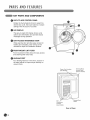 8
8
-
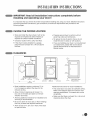 9
9
-
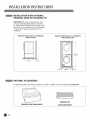 10
10
-
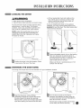 11
11
-
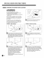 12
12
-
 13
13
-
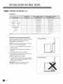 14
14
-
 15
15
-
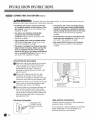 16
16
-
 17
17
-
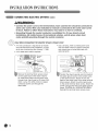 18
18
-
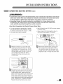 19
19
-
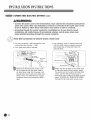 20
20
-
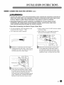 21
21
-
 22
22
-
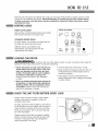 23
23
-
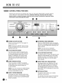 24
24
-
 25
25
-
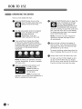 26
26
-
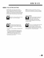 27
27
-
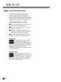 28
28
-
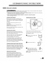 29
29
-
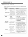 30
30
-
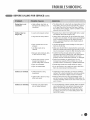 31
31
-
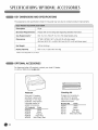 32
32
-
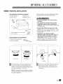 33
33
-
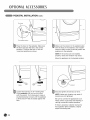 34
34
-
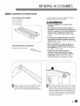 35
35
-
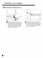 36
36
-
 37
37
-
 38
38
-
 39
39
-
 40
40
-
 41
41
-
 42
42
-
 43
43
-
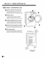 44
44
-
 45
45
-
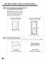 46
46
-
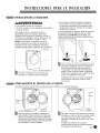 47
47
-
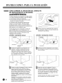 48
48
-
 49
49
-
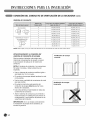 50
50
-
 51
51
-
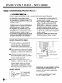 52
52
-
 53
53
-
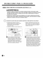 54
54
-
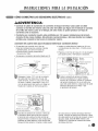 55
55
-
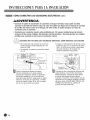 56
56
-
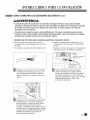 57
57
-
 58
58
-
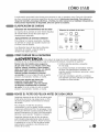 59
59
-
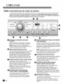 60
60
-
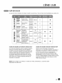 61
61
-
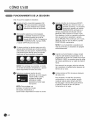 62
62
-
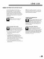 63
63
-
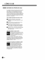 64
64
-
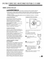 65
65
-
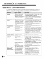 66
66
-
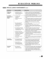 67
67
-
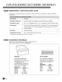 68
68
-
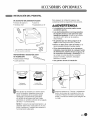 69
69
-
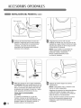 70
70
-
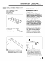 71
71
-
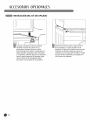 72
72
-
 73
73
-
 74
74
-
 75
75
-
 76
76


LG DLE1310W El manual del propietario
- Categoría
- Secadoras
- Tipo
- El manual del propietario
- Este manual también es adecuado para
En otros idiomas
- English: LG DLE1310W Owner's manual
Documentos relacionados
-
LG DLGX3002P El manual del propietario
-
LG DLGX2802W El manual del propietario
-
LG DLG5966W El manual del propietario
-
LG DLE2301W El manual del propietario
-
-
LG DLGX7188RM El manual del propietario
-
-
-
-
LG DLEX2901V El manual del propietario