LG DLG5966W El manual del propietario
- Categoría
- Secadoras de ropa eléctricas
- Tipo
- El manual del propietario

TROM TM
DRYE S
USER'SGUIDE&
INSTALLMiONINSTRUCTIONS
Before beginning Installation, read these
Instructions carefully. This wll simplify installation
and ensure that the dryer is installed correctly and
safely. Leave these instructions near the dryer
after installation for future reference.
TRO ,M
SECADORAS
To contact LG Electronics, 24 hours a day,
7 days a week:
1=800=243=0000
Or visit us on the Web at: us.lge.com
Pour contacter LG Electronics, 24 heures
par jour, 7 jours par semaine :
1=800=243=0000
ou visitez notre site Web &I'adresse :
us./ge.com
GLIIADE[ LISUARIOE
INSTRUcCiONESDE INSTA[AclON
Antes de comenzar la instalacion, lea atentamente
estas instrucciones. Esto simplificara la instalaciOn
y asegurara que la secadora esta instalada
en forma correcta y segura. Conserve estas
instrucciones cerca de la secadora luego de la
instalacion para futuras consultas.
M0dels/M0del0s
[-le¢[ri€/El(_€[rica
DLE5955W
DLE5955G
C,as/C,as
DLGBg66w
DLGBg66G
P/No. 3828EL3003S

INTRODUCTION
IMPORTANT SAFETY INSTRUCTIONS
Basic Safety Precautions ....................................... 3
What to Do if You Smell Gas .................................. 4
Grounding Instructions .......................................... 5
Safety Instructions for Installation ...................... 5, 6
Safety Instructions for Connecting Electricity ....... 7
PARTSAND FEATURES
Special Features ..................................................... 8
Key Parts and Components ................................... 9
INSTALLATION INSTRUCTIONS
Choose the Proper Location ................................ 10
Clearances ........................................................... 10
Installation With Optional
Pedestal Base or Stacking Kit.............................. 11
Leveling the Dryer ................................................ 12
Reversing the Door Swing .................................... 12
Changing the Dryer Vent Location ....................... 13
Venting the Dryer ............................................ 14, 15
Connecting Gas Dryers ................................... 16 17
Connecting Electric Dryers ................................... 18
Special Requirements for Manufactured
or Mobile Homes .................................................. 19
Final Installation Check ....................................... 19
Duct Condition Testing ......................................... 20
HOW TO USE
Sorting Loads ....................................................... 21
Loading the Dryer ................................................. 21
Check the Lint Filter Before Every Load ............... 21
Control Panel Features ......................................... 22
Cycle Guide .......................................................... 23
The Time and Status Display ............................... 24
The Duct Blockage Sensing System .................... 24
Operating the Dryer .............................................. 25
Cycle Setting Buttons .......................................... 26
Cycle Option Buttons .......................................... 27
Special Functions ................................................. 28
Custom Program .................................................. 28
CARE AND CLEANING
Regular Cleaning .................................................. 29
TROUBLESHOOTING
Before Calling for Service ............................... 30-32
SPECIFICATIONS/OPTIONAL
ACCESSORIES
Optional Accessories ........................................... 32
Pedestal Installation ....................................... 33, 34
Stacking Kit installation .................................. 35, 36
Key Dimensions and Specifications ..................... 36
WARRANTY
Product Information Registration ......................... 37
2
THANKYOU!
Congratulations on your purchase
and welcome to the LG family. Your
new LG Dryer combines the most
advanced drying sensor technology
with simple operation and high
efficiency. By following the
operating and care instructions
in this manual, your dryer will
provide you with many years of
reliable service.

! PORTANTSAFETYINSTRUCTIONS
READ ALL iNSTRUCTiONS BEFORE USE
WARNING Foryo.rsafeW,theinformationinthisman,alre,stbe
followed to minimize the risk of fire or explosion, electric shock, or to prevent
property damage, personal injury, or loss of life.
YOur Safety and the safety of others is very important.
We have provided many important safety messages in this manual and on your appliance. Always read
and obey all safety messages.
This iSthe safety alert symbol.
This symbol alerts you to potential hazards that can kill or hurt you and others.
All safety messages will follow the safety alert symbol and either the word DANGER or WARNING.
These words mean:
kDANGER: Youcanbe killed or seriously injured if you don't immediately follow instructions.
_h_WARN|NG-" You can be killed or seriously injured if you don't follow instructions.
All safety messages will tell you what the potential hazard is, tell you how the reduce the chance of
injury, and tell you what can happen if the instructions are not followed.
BASIC SAFETY PRECAUTIONS
&WARNING; To reduce the risk of fire, electric shock, or injury to persons when using this
appliance, follow basic precautions, including the following:
• Read all instructions before using the dryer.
• Before use, the dryer must be properly installed
as described in this manual.
Do not place items exposed to cooking oils in
your dryer. Items contaminated with cooking
oils may contribute to a chemical reaction that
could cause a load to catch fire.
Do not dry articles that have been previously
cleaned in, washed in, soaked in, or spotted
with gasoline, dry-cleaning solvents, other
flammable or explosive substances as they give
off vapors that could ignite or explode.
Do not reach into the dryer if the drum or any
other part is moving.
Do not repair or replace any part of the dryer
or attempt any servicing unless specifically
recommended in this Use and Care Guide or
in published user-repair instructions that you
understand and have the skills to carry out.
Do not tamper with controls.
Before the dryer is removed from service or
discarded, remove the door to the drying
compartment.
Do not allow children to play on or in the dryer.
Close supervision of children is necessary when
the dryer is used near children.
• Do not use fabric softeners or products to
eliminate static unless recommended by the
manufacturer of the fabric softener or product.
Do not use heat to dry articles containing
foam rubber or similarly textured rubber-like
materials.
Keep area around the exhaust opening and
adjacent surrounding areas free from the
accumulation of lint, dust, and dirt.
The interior of the dryer and exhaust vent
should be cleaned periodically by qualified
service personnel.
Do not install or store the dryer where it will be
exposed to the weather.
Always check the inside of the dryer for foreign
objects
Clean lint screen before or after each load.
The dryer must not be installed or stored in an
area where it will be exposed to water.

I PORTANTSAFETYINST UcTIONS
READ ALL iNSTRUCTiONS BEFORB USE
_WARNING Foryoursafe_,theinformationinthismanualmustbe
followed to minimize the risk of fire or explosion, electric shock, or to prevent
property damage, personal injury, or loss of life.
• Do not store or use gasoline or other
flammable vapors and liquids in the
vicinity of this appliance or any other
appliances.
• Installation and service must be
performed by a qualified installer,
service agency, or the gas supplier.
WHAT TO DO iF YOU SMELL GAS:
1. Do not try to light a match or cigarette,
or turn on any gas or electrical
appliance.
2. Do not touch any electrical switches.
Do not use any phone in your building.
3. Clear the room, building, or area of all
occupants.
4. immediately call your gas supplier from
a neighbor's phone. Follow the gas
supplier's instructions carefully.
5. if you cannot reach your gas
supplier, call the fire department.
CALIFORNIA SAFE DRINKING WATER AND TOXIC ENFORCEMENT ACT
This act requires the governor of California to publish a list of substances known to the state to cause
cancer, birth defects, or other reproductive harm and requires businesses to warn customers of potential
exposure to such substances.
Gas appliances can cause minor exposure to four of these substances, namely benzene, carbon monoxide,
formaldehyde, and soot, caused primarily by the incomplete combustion of natural gas or LP fuels.
Properly adjusted dryers will minimize incomplete combustion. Exposure to these substances can be
minimized further by properly venting the dryer to the outdoors.
4

! PORTANTSAFETYINSTRUCTIONS
READ ALL iNSTRUCTiONS BEFORE USE
WARNING Foryo.rsafe ',theinformationinthisman.alre,stbe
followed to minimize the risk of fire or explosion, electric shock, or to prevent
property damage, personal injury, or loss of life.
GROUNDING INSTRUCTIONS
This appliance must be grounded. In the event
of malfunction or breakdown, grounding will
reduce the risk of electric shock by providing
a path of least resistance for electric current.
This appliance must be equipped with a cord
having an equipment-grounding conductor and
a grounding plug. The plug must be plugged into
an appropriate outlet that is properly installed and
grounded in accordance with all local codes and
ordinances.
WARNING --,mproper
connection ofthe equipment-grounding
conductor can resultina riskofelectricshock.
Check with a qualified electrician or service
person ifyou are in doubt as to whether the
appliance is properly grounded.
Do not modify the plug provided with the
appliance. If it will not fit the outlet, have a proper
outlet installed by a qualified electrician.
This appliance must be connected to a grounded
metal, permanent wiring system or an equipment-
grounding conductor must be run with the circuit
conductors and connected to the equipment-
grounding terminal or lead on the appliance.
Electrical shock can result ifthe dryer is not
properly grounded.
SAFETY INSTRUCTIONS FOR INSTALLATION
,WARNING: To reduce the risk of fire, electric shock, or injury to persons when using this
appliance, follow basic precautions, including the following:
• Properly ground dryer to conform with all
governing codes and ordinances. Follow
details in the installation instructions. Electrical
shock can result ifthe dryer is not properly
grounded.
• Before use, the dryer must be properly
installed as described in this manual.
Electrical shock can result if the dryer is not
properly grounded.
• install and store the dryer where it will not be
exposed to temperatures below freezing or
exposed to the weather.
• All repairs and servicing must be performed
by an authorized servicer unless specifically
recommended in this Owner's Guide. Use
only authorized factory parts. Failure to follow
this warning can cause serious injury,fire,
electrical shock or death.
• To reduce the risk of electric shock, do not
install the dryer in humid spaces. Failure to
follow this warning can cause serious injury, fire,
electrical shock or death.
• Connect to a properly rated, protected,
and sized power circuit to avoid electrical
overload. Improper power circuit can melt,
creating electrical shock and/or fire hazard.
• Remove all packing items and dispose of all
shipping materials properly. Failure to do so
can result in death, explosion, fire or burns.
• Place dryer at least 18 in. above the floor
for a garage installation. Failure to do so can
result in death, explosion, fire or burns.
• Keep all packaging from children. Packaging
material can be dangerous for children. There is
a risk of suffocation.

I PORTANTSAFETYINST UcTIONS
READ ALL iNSTRUCTiONS BEFORE USE
WARNING Foryo.rsafew,theinformationinthisman.alre.stbe
followed to minimize the risk of fire or explosion, electric shock, or to prevent
property damage, personal injury, or loss of life.
SAFETY INSTRUCTIONS FOR INSTALLATION
Exhaust/Ducting:
• Gas dryers MUST be exhausted to the
outside. Failure to follow these instructions
can result in fire or death.
• The dryer exhaust system must be exhausted
to the outside of the dwelling, if the dryer is
not exhausted outdoors, some fine lint and
large amounts of moisture will be expelled
into the laundry area. An accumulation of
lint in any area of the home can create a health
and fire hazard.
,,Use only rigid metal or flexible metal 4-in.
diameter ductwork inside the dryer cabinet
or for exhausting to the outside. Use of
plastic or other combustible ductwork can
cause a fire. Punctured ductwork can cause
a fire if itcollapses or becomes otherwise
restricted in use or during installation.
• Ductwork is not provided with the dryer, and
you should obtain the necessary ductwork
locally. The end cap should have hinged
dampers to prevent backdraft when the dryer
is not in use. Failure to follow these instructions
can result infire or death.
• The exhaust duct must be 4 in. (10 cm) in
diameter with no obstructions. The exhaust
duct should be kept as short as possible.
Make sure to clean any old ducts before
installing your new dryer. Failure to follow
these instructions can result in fire or death.
',Rigid or semi rigid metal ducting is
recommended for use between the
dryer and the wall. in special installations
when it is impossible to make a connection
with the above recommendations, a UL=
listed flexible metal transition duct may be
used between the dryer and wall connection
only. The use of this ducting will affect drying
time. Failure to follow these instructions can
result in fire or death.
• DO NOT use sheet metal screws or other
fasteners which extend into the duct that
could catch lint and reduce the efficiency
of the exhaust system. Secure all joints with
duct tape. For complete details, follow the
Installation Instructions. Failure to follow these
instructions can result in fire or death.
6

! PORTANTSAFETYINSTRUCTIONS
READ ALL iNSTRUCTiONS BEFORE USE
_WARNING Foryo.rsafe_',theinformationinthisman.alre,stbe
followed to minimize the risk of fire or e×plosion, electric shock, or to prevent
property damage, personal injury, or loss of life.
SAFETY iNSTRUCTiONS FOR CONNECTING ELECTRiCiTY
&WARNING: To reduce the risk of fire, electric shock, or injury to persons when using this
appliance, follow basic precautions, including the following:
• Do not, under any circumstances, cut or
remove the ground prong from the power
cord. To prevent personal injury or damage to
the dryer, the electrical power cord must be
plugged into a properly grounded outlet.
• For personal safety, this dryer must be
properly grounded. Failure to do so can result
in electrical shock or injury.
• Refer to the installation instructions in this
manual for specific electrical requirements
for your model. Failure to follow these
instructions can create an electrical shock
hazard and/or a fire hazard.
• This dryer must be plugged into a properly
grounded outlet. Electrical shock can result if
the dryer is not properly grounded. Have the
wall outlet and circuit checked by a qualified
electrician to make sure the outlet is properly
grounded. Failure to follow these instructions
can create an electrical shock hazard and/or a
fire hazard.
• The dryer should always be plugged into
its own individual electrical outlet which
has a voltage rating that matches the rating
plate. This provides the best performance
and also prevents overloading house wiring
circuits which could cause a fire hazard from
overheated wires.
• Never unplug your dryer by pulling on the
power cord. Always grip plug firmly and pull
straight out from the outlet. The power cord
can be damaged, resulting in a risk of fire and
electrical shock.
• Repair or replace immediately all power
cords that have become frayed or otherwise
damaged. Do not use a cord that shows
cracks or abrasion damage along its length
or at either end. These power cord can melt,
creating electrical shock and/or fire hazard.
= When installing or moving the dryer, be
careful not to pinch, crush, or damage
the power cord. This will prevent injury and
prevent damage to the dryer from fire and
electrical shock.
SAVE THESB iNSTRUCTiONS

PARTSAND FEATURES
SPECIAL FEATURES
O EASY-TO-USE CONTROL PANEL
Rotate the Cycle Selector Knob to select the
desired dry cycle. Adjust settings and add cycle
options with the touch of a button.
O
O
EASY-ACCESS REVERSIBLE DOOR
Wide-opening door provides easy access for
loading and unloading. Door swing can be
reversed to adjust for installation location.
ULTRA=CAPACITY STAINLESS STEEL DRUM
WITH DRUM LIGHT
The ultra-large stainless steel drum offers
superior durability. The drum is equipped with a
yellow light that illuminates when the dryer door
is open and turns off when the door is closed.
O
FLOWSENSE MDUCT/FILTER BLOCKAGE
SENSING SYSTEM
The FlowSense TMduct/filter blockage sensing
system detects and alerts you to blockages in the
filter and ductwork that reduce exhaust flow from
the dryer. This not only helps prevent fires and
save lives, it can improve operating efficiency and
help minimize service calls, saving you money.
8

PARTSAND FEATURES
KEY PARTS AND COMPONENTS
In addition to the special features and
components outlined in the Special Features
section, there are several other important
components that are referenced in this manual.
O FRONT=MOUNT LiNT FILTER
Front-mounted lint filter allows for easy access
and cleaning after every load.
O
O
LEVELING FEET
Four leveling feet (two in the front, and two in
the back) adjust to improve dryer stability on
uneven floors.
DRYING RACK
Use the drying rack with the RACK DRY cycle
option. The drying rack allows items, such as
sweaters, delicates, and gym shoes, to be placed
in a flat position for drying. Terminal Block
Access Panel
(Electric Models)
Power
Cord
Location
(Gas
Models)
Included Accessories
O Drying Rack
Gas
Connection
Location
(Gas Models)
Exhaust Duct
Outlet
Rear of Dryer
(Electric Model
Shown)

INSTAL[ATION INST UCTIONS
iMPORTANT: Read all installation instructions completely before
installing and operating your dryer!
It is important that you review this entire manual before installing and using your dryer. Detailed instructions
concerning electrical connections, gas connections, and exhaust requirements are provided on the
following pages.
CHOOSE THE PROPER LOCATION
• Store and install the dryer where it will not be
exposed to temperatures below freezing or
exposed to outdoor weather conditions.
Choose a location with a solid, level floor.
If the dryer is being installed in a garage,
place the dryer at least 18 in. (46 cm) above
the floor.
Properly ground dryer to conform with all
governing codes and ordinances.
To reduce the risk of electric shock, do not
install the dryer in damp or wet locations.
If you are installing your dryer in a manufactured
or mobile home, please refer to the section
Special Requirements for Manufactured or
Mobile Homes.
CLEARANCES
18"
o20c Ti 45;7g
4"_ 1_30"_ 1_-4"
(10 cm) (76.1 cm) (10 cm)
50"_
(127 cm)
oo
1"_11_ 27-_11_1"
(2.54 cm) (68,6 cm) (2.54 cm)
3"
(7.6_m)
48 in.2
(310 cm2)
24 in.2
(155 cm _)
3"
(7.6cm)
Closet Door Vent
Requirements
....J
• Most installations require a minimum 5V2in.
(14 cm) clearance behind the dryer for the
exhaust ducting.
Allow minimum clearances of at least 1 in.
(2.5 cm) on the sides and back to minimize
vibration and noise.
Allowing additional clearance for installation and
servicing is recommended.
Be sure to allow for wall, door, or floor moldings
that may increase the required clearances.
Allow at least 24 in. (61 cm) in front of the dryer
to open the door.
Additional Instructions for closet installations:
The closet door must allow for sufficient airflow.
Refer to the diagram above for minimum vent
opening requirements. A Iouvered door is also
acceptable.
Make sure that there is at least 18 in. (46 cm) of
clearance above the dryer.
10

INSTALLATIONINSTRUCTIONS
INSTALLATIONS WITH OPTIONAL
PEDESTAL BASE OR STACKING KIT
iMPORTANT: If you are installing your dryer
using an optional pedestal base or stacking
kit, please refer to Optional Accessories in this
manual or to the instructions for your pedestal
or stacking kit before proceeding with the
installation.
Required Dimensions for installation
With Pedestal
Required Dimensions for Installation
With Stacking Kit
77V2"
[190.5 cm)
I_ 30,,_1 -_4,,
(76.1 cm) (10 cm)
1"_--II_ 27-_11_1"
(2.54 cm) (68.6 cm) (2.54 cm)
OPTIONAL ACCESSORIES
For these and other LG products, contact your local LG dealer, or visit our Web site at us.lge.com.
_q
Pedestal (sold separately) Stacking Kit (sold separately)
1t

iNSTALLATIONINST UCTIONS
LEVELING THE DRYER
To ensure that the dryer provides optimal drying
performance, it must be level. To minimize
vibration, noise, and unwanted movement, the
floor must be a perfectly level, solid surface.
NOTE: Adjust the leveling feet only as far as
necessary to level the dryer. Extending the
leveling feet more than necessary can cause
the dryer to vibrate.
• All four leveling feet must rest solidly on the
floor. Gently push on the top corners of the
dryer to make sure that the dryer does not
rock from corner to corner.
If you are installing the dryer on the optional
pedestal, you must use the leveling feet on the
pedestal to level the dryer. The dryer leveling feet
should be fully retracted.
g Feet
Position the dryer in the final location. Place
a level across the top of the dryer.
Use an adjustable wrench to turn the leveling
feet. Turn clockwise to raise the dryer or
counterclockwise to lower it. Raise or lower
the leveling feet until dryer is level from
side to side and front to back.
Make sure that all 4 leveling feet are in firm
contact with the floor.
REVERSING THE DOOR SWING
The swing of the dryer door can be reversed to fit your installation location.
12
Door
Latch
Hinge
Latch Screws ---'-'_% Screws
........................ ,/
Open the dryer door. Using a Phillips screw-
driver, remove the 2 screws that secure
the door hinge to the dryer door opening.
Remove the 4 screws from the latch side of the
dryer door opening, and remove the door latch.
Latch
Screws
"_-. /
\x _x
xx x
_ Hinge
_f Screws
Turn the door around so the hinge is
reversed, and reattach the door using the
2 screws previously removed. Reinstall the
door latch and the 4 screws.
Test the door swing to make sure the door
moves freely and latches securely.

INSTALLATIONINSTRUCTIONS
CHANGING THE DRYER VENT LOCATION
Your new dryer is shipped to vent to the rear.
It can also be configured to vent to the bottom
or side (right-side venting is not available on
gas models).
An adapter kit, part number 383EEL9001 B,
may be purchased from your LG retailer. This
kit contains the necessary duct components to
change the dryer vent location.
Retaining
Screw
Rear
Exhaust Duct
I
Remove the rear exhaust duct retaining
screw. Pull out the exhaust duct.
OPTION 1: Side Venting
Press the tabs on the knockout and carefully
remove the knockout for the desired vent
opening (right-side venting is not available on
gas models). Press the adapter duct onto the
blower housing and secure to the base of the
dryer as shown.
Cover
Plate
Elbow <38 om)
,/
Preassemble a 4-in. (10 cm) elbow to the next
4-in. (10 cm) duct section, and secure all joints
with duct tape. Be sure that the male end of
the elbow faces AWAY from the dryer.
Insert the elbow/duct assembly through the
side opening and press it onto the adapter
duct. Secure in place with duct tape.
Be sure that the male end of the duct
protrudes 1V2in. (3.8 cm) to connect the
remaining ductwork.
Attach cover plate to the back of the dryer with
included screw.
OPTION 2: Bottom Venting
f"_ Adapter
Duct
Bracket
Press the adapter duct onto the blower
housing and secure to the base of the dryer
as shown.
Cover
Plate
Elbow
__J
Insert the 4-in. (10 cm) elbow through the
rear opening and press it onto the adapter
duct. Be sure that the male end of the elbow
faces down through hole in the bottom of the
dryer. Secure in place with duct tape.
Attach the cover plate to the back of the
dryer with included screw.
15

INSTALLATIONINST UCTIONS
VENTING THE DRYER
&WARN|NG: To reduce the risk of fire, electric shock, or injury to persons when using this
appliance, follow basic precautions, including the following:
• Do not crush or collapse ductwork. Failure
to follow these instructions can result in fire or
death.
• Do not allow ductwork to rest on or
contact sharp objects. Failure to follow these
instructions can result in fire or death.
• if connecting to existing ductwork, make
sure it is suitable and clean before installing
the dryer. Failure to follow these instructions
can result in fire or death.
• Venting must conform to local building
codes. Failure to follow these instructions can
result in fire or death.
• Gas dryers MUST exhaust to the outdoors.
Failure to follow these instructions can result in
fire or death.
= Use only 4-in. (10 cm} rigid or flexible metal
ductwork inside the dryer cabinet and
for venting outside. Failure to follow these
instructions can result in fire or death.
• To reduce the risk of fire, combustion, or
accumulation of combustible gases, DO
NOT exhaust dryer air into an enclosed and
unventilated area, such as an attic, wall,
ceiling, crawl space, chimney, gas vent, or
concealed space of a building. Failure to
follow these instructions can result in fire
or death.
• To reduce the risk of fire, DO NOT exhaust
the dryer with plastic or thin foil ducting.
Failure to follow these instructions can result in
fire or death.
• The exhaust duct must be 4 in. {10 cm) in
diameter with no obstructions. The exhaust
duct should be kept as short as possible.
Make sure to clean any old ducts before
installing your new dryer. Failure to follow
these instructions can result in fire or death.
• Rigid or semirigid metal ducting is
recommended for use between the dryer
and the wall. in special installations when it
is impossible to make a connection with the
above recommendations, a UL-listed flexible
metal transition duct may be used between
the dryer and wall connection only. The use
of this ducting will affect drying time. Failure
to follow these instructions can result in fire or
death.
= DO NOT use sheet metal screws or other
fasteners which extend into the duct that
could catch lint and reduce the efficiency of
the exhaust system. Secure all joints with
duct tape. Failure to follow these instructions
can result in fire or death.
• To maximize operating results, please
observe the duct length limitations noted
in the chart above. Failure to follow these
instructions can result in fire or death.
• Ductwork is not provided with the dryer.
You should obtain the necessary ductwork
locally. The end cap should have hinged
dampers to prevent backdraft when the
dryer is not in use. Failure to follow these
instructions can result in fire or death.
14

INSTALLATIONINSTRUCTIONS
VENTING THE DRYER (cont.)
Ductwork
0 65 ft. (19.8 m) 45 ft. (13.7 m)
Recommended 1 55 ft. (16.8 m) 35 ft. (10.7 m)
2 47 ft. (13.7 m) 30 ft. (9.1 m)
3 36 ft. (11.0 m) 25 ft. (7.6 m)
/_02o,nl /_02oml 4 28 ft. (8.5 m) 20 ft. (6.1 m)
Use Only for Short 0 55 ft. (16.8 m) 35 ft. (10.7 m)
Run Installations 1 47 ft. (13.7 m) 27 ft. (8.1 m)
2 41 ft. (12.5 m) 21 ft. (6.4 m)
3 30ft. (9.1 m) 17ft. (5.2 m)
/........, 4 22 ft. (6.7 m) _../
NOTE: Deduct 6 ft. (1.8 m) for each additional elbow. It is not recommended to use more than four 90° elbows.
Routing and Connecting Ductwork
Follow the guidelines below to maximize drying
performance and reduce lint buildup and
condensation in the ductwork.
NOTE: Ductwork and fittings are NOT included
and must be purchased separately.
• Use 4-in. (10 cm) diameter rigid or semirigid
metal ductwork.
• The exhaust duct run should be as short as
possible.
• Use as few elbow joints as possible.
The male end of each section of exhaust duct
must point away from the dryer.
Use duct tape on all duct joints.
Insulate ductwork that runs through unheated
areas in order to reduce condensation and lint
buildup on duct surfaces.
iMPORTANT: Failure to exhaust the dryer
correctly will void the dryer's warranty.
Correct Venting
incorrect Venting
15

INSTALLATIONINST UCTIONS
CONNECTING GAS DRYERS
4_I_WARNING -! To reduce the risk of fire, electric shock, or injury to persons when using this
appliance, follow basic precautions, including the following:
• Gas supply requirements:
As shipped from the factory, this dryer
is configured for use with natural gas.
It can be converted for use with LP (Liquefied
Propane) gas. Gas pressure
must not exceed 13 in. water column.
• A qualified service or gas company technician
must connect the dryer to the gas service.
Failure to do so can result in fire, explosion, or
death.
• Isolate the dryer from the gas supply system
by closing its individual manual shutoff valve
during any pressure testing of the gas supply.
Failure to do so can result in fire, explosion, or
death.
• Supply line requirements:
Your laundry room must have a rigid gas
supply line to your dryer, in the United States,
an individual manual shutoff valve MUST be
installed within at least 6 ft. (1.8 m) of the
dryer, in accordance with the National Fuel
Gas Code ANSI Z223.1. A 1/8=in. NPT pipe
plug must be installed. Failure to do so can
result in fire, explosion, or death.
= If using a rigid pipe, the rigid pipe should be
1/2=in. IPS. If acceptable under local codes
and ordinances and when acceptable to your
gas supplier, 3/8=in. approved tubing may be
used where lengths are less than 20 ft. (6.1
m). Larger tubing should be used for lengths
in excess of 20 ft. (6.1 m). Failure to do so can
result in fire, explosion, or death.
• Connect the dryer to the type of gas shown
on the nameplate. Failure to do so can result in
fire, explosion, or death.
• To prevent contamination of the gas valve,
purge the gas supply of air and sediment
before connecting the gas supply to the dryer.
Before tightening the connection between the
gas supply and the dryer, purge remaining air
until the odor of gas is detected. Failure to do
so can result infire, explosion, or death.
DO NOT use an open flame to inspect for
gas leaks. Use a noncorrosive leak-detection
fluid. Failure to do so can result infire, explosion,
or death.
• Use only a new AGA- or CSA-certified gas
supply line with flexible stainless steel
connectors. Failure to do so can result in fire,
explosion, or death.
• Securely tighten all gas connections. Failure to
do so can result infire, explosion, or death.
Use Teflon®tape or a pipe=joint compound
that is insoluble in Liquefied Petroleum (LP)
gas on all pipe threads. Failure to do so can
result in fire, explosion, or death.
DO NOT attempt any disassembly of the
dryer; any disassembly requires the attention
and tools of an authorized and qualified
service person or company. Failure to do so
can result infire, explosion, or death.
Electrical Requirements for Gas Models Only
• Do not, under any circumstances, cut or
remove the third (ground) prong from the
power cord. Failure to follow this warning can
result infire, explosion, or death.
For personal safety, this dryer must be
properly grounded. Failure to follow this warning
can result in fire, explosion, or death.
• The power cord of this dryer is equipped with
a 3=prong (grounding) plug which mates with
a standard 3=prong (grounding) wall outlet
to minimize the possibility of electric shock
hazard from this appliance. Failure to follow
this warning can result in fire, explosion,
or death.
• This dryer must be plugged into a
120=VAC, 60=Hz. grounded outlet protected by
a 15=ampere fuse or circuit breaker. Failure to
follow this warning can result infire, explosion, or
death.
Where a standard 2=prong wall outlet is
encountered, it is your personal responsibility
and obligation to have it replaced with a
properly grounded 3-prong wall ouUet. Failure
to follow this warning can result in fire, explosion,
or death.
16

INSTALLATIONINSTRUCTIONS
CONNECTING GAS DRYERS (cont.)
_!_WARNING: To reduce the risk of fire, electric shock, or injury to persons when using this
appliance, follow basic precautions, including the following:
• installation and service must be performed
by a qualified installer, service agency, or the
gas supplier. Failure to do so can result in fire,
explosion, or death.
• Use only a new stainless steel flexible
connector and a new AGA-certified
connector. Failure to do so can result in fire,
explosion, or death.
• A gas shutoff valve must be installed within
6 ft. (1.8 m) of the dryer. Failure to do so can
result in fire, explosion, or death.
• The dryer is configured for Natural Gas when
shipped from the factory. Make sure that the
dryer is equipped with the correct burner
nozzle for the type of gas being used (Natural
Gas or Liquefied Petroleum). Failure to do so
can result in fire, explosion, or death.
• If necessary, the correct nozzle (for the LP
nozzle kit order part number 4948EL4002B}
should be installed by a qualified technician
and the change should be noted on the dryer.
Failure to do so can result in fire, explosion,
or death.
• All connections must be in accordance with
local codes and regulations. Failure to do so
can result in fire, explosion, or death.
• Gas dryers MUST exhaust to the outdoors.
Failure to do so can result in fire, explosion, or
death.
Connecting the Gas Supply
O Make sure that the gas supply to the laundry
room is turned OFR Confirm that the type
of gas available in your laundry room is
appropriate for the dryer. The dryer is
prepared for Natural Gas with a 3/8-in. NPT
gas connection.
O Remove the shipping cap from the gas
connection at the back of the dryer. Be
careful not to damage the threads of the gas
connector when removing the shipping cap.
O Connect the dryer to your laundry room's gas
supply using a new flexible stainless steel
connector with a 3/8-in. NPT fitting.
O Securely all connections between the
tighten
dryer and your laundry room's gas supply.
Turn on your laundry room's gas supply and
check all pipe connections (both internal and
external) for gas leaks with a noncorrosive
leak-detection fluid.
Electrical Connection
Plug dryer into a
120-VAC, 60-Hz.
grounded 3-prong
outlet.
Flexible Connector
High-Altitude Installations
The BTU rating of this dryer is AGA-certified for
elevations below 10,000 feet.
If your gas dryer is being installed at an elevation
above 10,000 feet, it must be derated by a
qualified technician or gas supplier.
17

INSTALLATIONINST UCTIONS
CONNECTING ELECTRICDRYERS
&WAI:ININ6: To help prevent fire, electric shock, serious injury or death, the wiring and
grounding must conform to the latest edition of the National Electrical Code, ANSl/NFPA 70 and all
applicable local regulations. Please contact a qualified electrician to check your home's wiring and
fuses to ensure that your home has adequate electrical power to operate the dryer.
Electrical Requirements for Electric Models Only
WARI ilI iG" Toreducetheriskoffire,electricshock,orinjurytopersonswhenusingthis
appliance, follow basic precautions, including the following:
This dryer must be connected to a grounded
metal, permanent wiring system, or an
equipment= rounding conductor must be run
with the circuit conductors and connected
to the equipment=grounding terminal or lead
on the dryer. Failure to do so can result in fire,
explosion, or death.
The dryer has its own terminal block that
must be connected to a separate 240 VAC,
60-Hertz, single=phase circuit, fused at 30
amperes (the circuit must be fused on both
sides of the line). ELECTRICAL SERVICE
FOR THE DRYER SHOULD BE OF THE
MAXIMUM RATE VOLTAGE LISTED ON THE
NAMEPLATE. DO NOT CONNECT DRYER TO
110-, 115-, OR 120-VOLT CIRCUIT. Heating
elements are available for field installation
in dryers which are to be connected to an
electrical service of a different voltage than
that listed on the rating plate. Failure to follow
these instructions can result in fire, explosion,
or death.
• If branch circuit to dryer is 15 ft. (4.5 m)
or less in length, use UL (Underwriters
Laboratories) listed No.-10 AWG wire
(copper wire only), or as required by local
codes, if over 15 ft. (4.50 m), use UL=listed
No.=8 AWG wire (copper wire only), or as
required by local codes. Allow sufficient
slack in wiring so dryer can be moved from
its normal location when necessary. Failure
to do so can result in fire, explosion, or death.
= The power cord (pigtail) connection between
wall receptacle and dryer terminal block
IS NOT supplied with dryer. Type of pigtail
and gauge of wire must conform to local
codes and with instructions on the following
pages. Failure to follow these instructions can
result in fire, explosion, or death.
• A 4-wire connection is required for all mobile
and manufactured home installations, as
well as all new construction after January
1, 1996. A 4=wire connection must be used
where local codes do not permit grounding
through the neutral wire. Failure to do so can
result in fire, explosion, or death.
Special Electrical Requirements for Mobile or Manufactured Homes
&WARN|NG; To reduce the risk of fire, electric shock, or injury to persons when using this
appliance, follow basic precautions, including the following:
• Any installation in a manufactured or mobile • A 4=wire connection is required for all mobile
home must comply with the Manufactured and manufactured home installations, as well
Home Construction and Safety Standards as all new construction after January 1, 1996.
Title 24 CFR, Part 32-80 or Standard CAN/ Failure to do so can result in fire, explosion, or
CSA0Z240 MH and local codes and ordinances, death.
18

INSTALLATIONINSTRUCTIONS
SPECIAL REOUIREMENTS FOR MANUFACTURED OR MOBILE HOMES
Any installation in a manufactured or mobile
home must comply with the Manufactured Home
Construction and Safety Standards Title 24 CFR,
Part 32-80 or Standard CAN/CSAOZ240 MH and
local codes and ordinances. If you are uncertain
whether your proposed installation will comply
with these standards, please contact a service
and installation professional for assistance.
• A gas dryer must be permanently attached to
the floor.
The electrical connection for an electric dryer
must be a 4-wire connection. More detailed
information concerning the electrical connection
is provided in the section Connecting Electric
Dryers.
To reduce the risk of combustion and fire, the
dryer must be vented to the outside.
DO NOT vent the dryer under a manufactured
home or mobile home.
Electric dryers may be vented to the outside
using the back, left, right, or bottom panel.
Gas dryers may be vented to the outside using
the back, left, or bottom panel. Gas dryers may
not be vented to the outside using the right side
panel because of the burner housing.
The dryer exhaust duct must be affixed securely
to the manufactured or mobile home structure,
and the exhaust duct must be made of a
material that will resist fire and combustion.
It is recommended that you use a rigid or
flexible metal duct.
DO NOT connect the dryer exhaust duct
to any other duct, vent, chimney, or other
exhaust duct.
Make sure the dryer has adequate access to
outside fresh air to ensure proper operation.
The opening for outside fresh air must be at
least 25 in2 (163 cm2).
It is important that the clearance of the duct
from any combustible construction be at least
2 in. (5 cm), and when venting the dryer to
the outdoors, the dryer can be installed with a
clearance of 1 in. (2.5 cm) at the sides and back
of the dryer.
Please be aware that venting materials are
not supplied with the dryer. You should obtain
the venting materials necessary for proper
installation.
FINAL iNSTALLATiON CHECK
Once you have completed the installation of
the dryer and it is in its final location, confirm
proper operation with the following tests.
Testing Dryer Heating
GAS MODELS
Close the dryer door, press the ON/OFF switch
to turn the dryer on, and start the dryer on a heat
setting. When the dryer starts, the igniter should
ignite the main burner.
NOTE: If all air is not purged from the gas line,
the gas igniter may turn off before the main
burner ignites. If this happens, the igniter will
reattempt gas ignition after approximately
two minutes.
ELECTRIC MODELS
Close the dryer door, press the ON/OFF switch
to turn the dryer on, and start the dryer on a heat
setting. The exhaust air should be warm after the
dryer has been operating for 3 minutes.
Checking Airflow
Effective dryer operation requires proper airflow.
The adequacy of the airflow can be measured
by evaluating the static pressure. Static pressure
in the exhaust duct can be measured with
a manometer, placed on the exhaust duct
approximately 2 ft. (60.9 cm) from the dryer.
Static pressure in the exhaust duct should not
exceed 0.6 in. (1.5 cm). The dryer should be
checked while the dryer is running with no load.
Checking Levelness
Once the dryer is in its final location, recheck
the dryer to be sure it is level. Make sure it is
level front to back and side to side, and that
all 4 leveling feet are firmly on the floor.
19

iNSTALLATIONINST UCTIONS
DUCT CONDITION TESTING
Your dryer features FIowSense TM, an innovative
sensor system that automatically detects
blockages and restrictions in dryer ductwork.
Keeping ductwork clean of lint build-up and free
of restrictions allows clothes to dry faster, reduces
energy use, and helps prevent fires.
When the dryer is first installed, the duct condition
test must be performed. This alerts you to any
existing problems before the dryer is used. The
dryer also saves this information to compare and
measure future changes.
To activate the duct condition test cycle:
O Press and hold the DAMP DRY BEEP and
TEMP CONTROL buttons at the same time.
While holding these buttons, press POWER
ON/OFR
O The dryer will show InS in the number display
to indicate that it is in duct condition testing
mode.
O Press START/PAUSE. The dryer win run for
approximately 2 minutes to test
for blockages or restrictions to air
flow in the ductwork.
If no bars are shown in the display,
the ductwork is free from blockages or
restrictions.
If all bars are Nt,the dryer ductwork
has a blockage that needs to be
removed immediately.
Correct Venting
:TcJ
I
f_
Restricted or Blocked Airflow
Avoid long runs or runs with multiple elbows
or bends.
Check for blockages and lint buildup.
Make sure the ductwork is not crushed
or restricted.
0 %...................................................................................................................................................................................................................................................................................................................................................................._J

OWTO USE
SORTING LOADS
Fabric care Labels
Most articles of clothing feature fabric care labels
that include instructions for proper care.
Grouping Similar Items
For best results, sort clothes into loads that can
be dried with the same drying cycle.
Different fabrics have different care requirements,
and some fabrics will dry
more quickly than others.
f careLa els
Tumble
dry
Dry Normal PermanentPress/
wrinkle resistant
Donotdry
Gentle/ DonottumNedry (usedwith
delicate do not wash}
Heat (_) (_ Q O
setting
LOADING THE DRYER
WARNING: To reduce the risk of fire, electric shock, or injury to persons when using this
appliance, follow basic precautions, including the following:
• Check all pockets to make sure that they are
empty. Items such as clips, pens, coins, and
keys can damage both your dryer and your
clothes. Flammable objects such as lighters
or matches could ignite, causing a fire.
Failure to do so can result in fire, explosion, or
death.
• Never dry clothes that have been exposed to
oil, gasoline, or other flammable substances.
washing clothes will not completely remove
oil residues. Failure to obey this warning can
result in fire, explosion, or death.
• Combine large and small items in a load.
• Damp clothes will expand as they dry. Do not
overload the dryer; clothes require room to
tumble to dry properly.
• Close zippers, hooks, and drawstrings to
prevent these items from snagging or tangling
on other clothes.
CHECK THE LINT FILTER BEFORE EVERY LOAD
The CHECK FILTER indicator will light before
each load to remind you to make sure
the lint filter is clean before starting a
new load. It will also come on during
a load if the lint filter is clogged to let
you know that the lint filter needs to be cleaned;
a clogged lint filter will increase drying times.
To clean, pull the lint filter straight up and roll any
lint off the filter with your fingers. Do not rinse or
wash the filter to remove lint. Push the lint filter
firmly back into place. See "Care and Cleaning"
for more information.
Always ensure the lint filter is properly installed
before running the dryer. Running the dryer with
a loose or missing lint filter may damage the
dryer and articles in the dryer.
f ........................................................................................................................................... %
Lint Filter
21

OWTO USE
CONTROL PANEL FEATURES
Following are instructions for starting and using your new dryer. Please refer to specific sections
of this manual for more detailed information. Important warning: TO reduce the risk of fire,
electric shock, or injury to persons, read this entire manual, including the Important Safety
Instructions, before operating this dryer.
O
0
e
O
POWER ON/OFF BUTTON
Press to turn the dryer ON. Press again to
turn the dryer OFR
NOTE: Pressing the ON/OFF button during
a cycle will cancel that cycle and any load
settings will be lost.
CYCLE SELECTOR KNOB
Turn this knob to select the desired cycle.
Once the desired cycle has been selected,
the standard presets will be shown in the
display. On MANUAL DRY cycles, these
settings can be adjusted using the cycle
settings buttons anytime before starting
the cycle.
START/PAUSE BUTTON
Press this button to START the selected
cycle. If the dryer is running, use this button
to PAUSE the cycle without losing the
current settings.
NOTE: If you do not press the START/PAUSE
button to resume a cycle within 8 minutes,
the dryer automatically turns off.
O CYCLE SETTING BUTTONS
Use these buttons to adjust the desired cycle
settings for the selected cycle.
O
O
TiME AND STATUS DISPLAY
The display shows the settings, estimated
time remaining, options, and status messages
for your dryer.
OPTION BUTTONS
The option buttons allow you to select
additional cycle options. Certain buttons
also allow you to activate special functions
by pressing and holding the button for
3 seconds.
For detailed information about the individual
options, please see the following pages.
O
MORE TIME/LESS TIME BUTTONS
Use these buttons with MANUAL DRY and
TIME DRY cycles to adjust the drying time.
Press the MORE TIME button to increase
the selected manual cycle time by a minute;
press LESS TIME to decrease the cycle time
by a minute.
22

OWTO USE
CYCLE GUIDE
The cycle guide below shows the options and recommended fabric types for each cycle.
HeavyDub]
Co,on/
Towels
Normal
Perm,Press
Delicates
Ultra
Delicate
Speed Dry
FreshenUp
Air Dry
Time Dry
Jeans,
heavyweightitems
Denims,towels,
heavycottons
Workclothes,
corduroys,etc.
Permanentpress,
syntheticitems
Lingerie,sheets,
blouses
Workoutwear,
sheeror lacy
garments
Forsmallloads
with short
dryingtimes
Forremoving
lightwrinkles
fromclothing
Foritemsthat
requireheat-free
dryingsuchas
plasticsor rubber
Forgeneraldrying;
time,temperature,
andoptionscan be
setmanually
Normal
Adjustable
Normal
Adjustable
Normal
Adjustable
Normal
Adjustable
Normal
Adjustable
Normal
Adjustable
Off
Off
Off
Off
High
Med.High
Medium
High
Low
UltraLow
High
Adjustable
High
Adjustable
NoHeat
High
Adjustable
54
55
41
36
32
34
25
Adjustable
20
Adjustable
30
Adjustable
40
Adjustable
Sensor Dry Cycles
Sensor Dry cycles utilize LG's unique dual sensor
system to detect and compare the moisture level
in clothes and in the air and adjust the drying
time as needed to ensure superior results. The
dryer automatically sets the dryness level and
temperature at the recommended setting for each
cycle. The estimated time remaining will
be shown in the display.
Manual Dry Cycles
Use Manual Dry cycles to select a specific
amount of drying time and a drying temperature.
When a Manual Dry cycle is selected, the
ESTIMATED TIME REMAINING display shows
the actual time remaining in your cycle. You can
change the actual time in the cycle by pressing
MORE TIME or LESS TIME.
NOTE: To protect your garments, not every dry level, temperature, or option is available
with every cycle.
J
25

OWTO USE
THE TIME AND STATUS DISPLAY
The display shows the settings, estimated time remaining, options, and status messages for
your dryer.
_]_ ESTIMATED TiME REMAiNiNG
When the START/PAUSE button is pressed,
the display will indicate the estimated time
remaining for the selected drying cycle.
O
CYCLE COMPLETION INDICATOR WITH
CHECK RLTER REMINDER
This portion of the display shows which
stage of the drying cycle is currently
underway (CHECK FILTER, DRYING,
COOLING, or WRINKLE CARE).
O
CHILD LOCK INDEATOR
When CHILD LOCK is set, the Child Lock
indicator will appear and all buttons are
disabled except the ON/OFF button. This
prevents children from changing settings
while the dryer is operating.
O
FLOW SENSE TM DUCT BLOCKAGE
SENSING SYSTEM INDICATOR
The FLOW SENSE TM duct blockage sensing
system detects and alerts you to blockages
in the ductwork that reduce exhaust flow
from the dryer. This not only helps prevent
fires and save lives, it can improve operating
efficiency and help minimize service calls,
saving you money.
lf no bars are shown in the
display, the ductwork is free from
blockages.
The more bars displayed, the
greater the blockage.
If all bars are lit, the dryer
ductwork has a blockage that
needs to be removed immediately.
24
O
LINT FETER INDICATOR
The dryer automatically detects reduced air
flow caused by a full lint filter. The
CHECK FILTER indicator will light
before each load as a reminder to
check the lint filter before starting
each load. If the lint filter becomes clogged
during a load, the indicator will come on to
let you know that the filter should be cleaned
immediately for maximum efficiency.
Always clean the lint filter before every cycle.

OWTO USE
OPERATING THE DRYER
once you have loaded the dryer:
O Press the ON/OFF button to turn the
on
dryer. The lights around the cycle
selector knob will illuminate.
O Turn the selector knob to the desired
cycle
cycle. The display will show
the preset Dry Level,
Temperature, Time, and
Option settings for that cycle.
Oil you to change settings
would like the
for that cycle, such as the dry level or
temperature, press the appropriate cycle
settings button(s) until the indicator light for
the desired setting is lit.
NOTE: To protect your garments, not every
dry level, temperature, or option is available
with every cycle.
O
Select any additional cycle options, such
as WRINKLE CARE, ANTI BACTERIAL, or
DAMP DRY BEEP, by pressing the button
for that option. The indicator light on the
button will light to show that option has been
selected. To deselect an option, press the
button again.
O Press the START/PAUSE button to begin the
cycle. The display will change,
and the dryer will display the
estimated (SENSOR DRY) or set
time (MANUAL DRY) remaining
and start tumbling. To pause the cycle at any
time, for example to clean the lint filter or to
remove a garment, open the dryer door or
press PAUSE. To resume the cycle where it
was stopped, press START/PAUSE again.
NOTE: If the dryer has been stopped for
more than 8 minutes, the dryer will turn
off automatically.
O
O
When the load is finished, the beeper (if
set) will sound. If you have set the Wrinkle
Care option, the dryer will tumble the load
periodically for up to 3 hours.
To prevent wrinkling, remove items from the
dryer immediately after the end of the cycle.
Always clean the lint filter after every cycle.
To clean, pull the lint filter straight up and
roll any lint off the filter with your fingers.
Do not rinse or wash the filter to remove lint.
Push the lint filter firmly back into place.
NOTE: To protect your garments, not every
dry level, temperature, or option is available
with every cycle.
25

OWTO USE
CYCLE SETTING BUTTONS
sensor Dry cycles have preset settings that are
selected automatically and cannot be changed.
Manual Dry cycles have default settings, but you
may also customize the settings using the cycle
setting buttons. Press the button for that setting
until the indicator light for the desired value is lit.
DRY LEVEL
Selects the level of
dryness for the cycle.
Press the DRY LEVEL
button until the indicator
light for the desired
setting is lit.
• This option is only available with SENSOR DRY
cycles.
The dryer will automatically adjust the cycle
time. Selecting VERY DRY or MORE DRY will
increase the cycle time, while LESS DRY or
DAMP DRY will decrease the cycle time.
Use a LESS DRY or DAMP DRY setting for
items that you wish to iron.
NOTE: To protect your garments, not every
dryness level, temperature, or option is available
with every cycle. See the Cycle Guide for details.
TIME DRY
Allows you to manually
select the drying time,
from 20 to 60 minutes, in
1O- minute increments.
Use this for small loads
or to remove wrinkles.
Press the TIME DRY
button until the indicator light for the desired
drying time is lit. Use the MORE TIME/
LESS TIME buttons to add or reduce the
drying time in 1-minute increments.
TEMP. CONTROL
Adjusts the temperature
setting from ULTRA LOW
to HIGH. This allows
precise care of your
fabrics and garments.
Press the TEMP
CONTROL button until
the indicator light for the desired setting is lit.
26

HO TO USE
CYCLE OPTION BUTTONS
Your dryer features several additional cycle
options to customize cycles to meet your
individual needs. Certain option buttons also
feature a special function (see the following page
for details) that can be activated by pressing and
holding that option button for 3 seconds.
To Add Cycle Options to a Cycle:
O Turn the and turn the selector
on
dryer cycle
knob to select the desired cycle.
O Use the buttons to the
cycle settings adjust
settings for that cycle.
O Press the cycle option button(s) for the
option you would like to add. A confirmation
message will be shown in the display.
O Press the START/PAUSE button to start the
cycle. The dryer will start automatically.
RACK DRY
Use RACK DRY with items, such as
wool sweaters, silk, and lingerie, that
should dry flat. RACK DRY can also
be used with items that should not be
tumbled dry, such as gym shoes or
stuffed animals.
NOTE: NEVER use the rack with a tumble
dry cycle.
To Install the Drying Rack
O With the dryer door open, slide the rack into
the dryer drum.
WRINKLE CARE
Selecting this option will tumble the
load periodically for up to 3 hours after
the selected cycle, or until the door is
opened. This is helpful in preventing
wrinkles when you are unable to immediately
remove items from the dryer.
ANTI BACTERIAL
This option will add a high heat setting
to reduce bacteria. It can only be used
with the HEAVY DUTY, COTTON/
TOWELS, and NORMAL cycles.
NOTE: Do not use this cycle with
delicate fabrics.
e Make sure it is seated evenly on the edge
of the inner door rim and resting flat on the
inside of the dryer.
NOTE: Be sure to remove the drying rack
after using the RACK DRY cycle.
DAMP DRY BEEP
With this option, the dryer will beep
when the load is approximately 80%
dry. This allows you to remove
faster- drying lightweight items or
items that you would like to iron or hang while still
slightly damp.
27

OWTO USE
SPEciAL FUNCTIONS
The option buttons also activate special
functions, including CHILD LOCK and
BEEPER ON/OFF. Press and hold the option
button marked with the special function
for 3 seconds to activate.
CHILD LOCK
Use this option to prevent unwanted
use of the dryer or to keep cycle
settings from being changed while the
dryer is operating. Press and hold the
RACK DRY button for 3 seconds to activate or
deactivate CHILD LOCK.
The lock icon will be shown in the display, and all
controls are disabled except the ON/OFF button.
The dryer can be locked during a cycle.
BEEPER ON/OFF
To turn the beeper off, press and hold
DAMP DRY BEEP for 3 seconds. Press
and hold again for 3 seconds to turn
the beeper back on.
* CUSTOM PROGRAM
If you have a special combination of
settings that you use frequently, you
can save these settings as a CUSTOM
PROGRAM.
To Save a Custom Program:
0 Turn on the dryer and turn the cycle selector
knob to select the desired cycle.
e Use the knobs to the
cycle setting adjust
settings for that cycle.
O Press cycle option button(s)
the for the
option(s) you would like to add.
O Press and hold the CUSTOM PROGRAM
button for 3 seconds.
NOTE: You may only save one custom
program at a time. Pressing and holding the
CUSTOM PROGRAM button will overwrite
any previously saved custom program.
To Recall a Custom Program:
t_ Turn on the dryer.
e Press the CUSTOM PROGRAM button.
O Press the START/PAUSE button to start
the cycle.
28

CAREANDclEANING
REGULAR CLEANING
_WARNING= To reduce the risk of fire, electric shock, or injury to persons when using this
appliance, follow basic precautions, including the following:
• Unplug the dryer before cleaning to avoid the risk of electric shock. Failure to follow this warning can
cause serious injury,fire, electrical shock or death.
= Never use harsh chemicals, abrasive cleaners, or solvents to clean the washer.
They will damage the finish.
Cleaning the Exterior
Proper care of your dryer can extend its life.
The outside of the machine can be cleaned with
warm water and a mild, nonabrasive household
detergent.
Immediately wipe off any spills with a soft,
damp cloth.
IMPORTANT: Do not use methylated spirits,
solvents, or similar products.
Never use steel wool or abrasive cleansers; they
can damage the surface.
Cleaning the Lint Filter
Lint Filter
Cleaning the Interior
Wipe around the door opening and seal with a
soft, damp cloth to prevent lint and dust buildup
that could damage the door seal.
Clean the window with a soft cloth dampened
with warm water and a mild, nonabrasive
household detergent; then wipe dry.
The stainless steel drum can be cleaned with
a conventional stainless steel cleaner, used
according to the manufacturer's specifications.
Never use steel wool or abrasive cleansers; they
can scratch or damage the surface.
Always clean the lint filter before every cycle or
when the CHECK FILTER indicator
lights during a cycle.
To clean, open the dryer door and
pull the lint filter straight up.
Then:
O Roll any lint off the filter with
your fingers, or
Cleaning Around and Under the Dryer
Vacuum lint and dust from around the dryer and
underneath it regularly. Vent ductwork should be
checked for lint buildup and cleaned at least once
per year. If any noticeable reduction in airflow or
drying performance occurs, immediately check
ductwork for obstructions and blockages.
Maintaining Ductwork
Vent ductwork should be checked for lint
buildup and cleaned at least once per year. If
any noticeable reduction in airflow or drying
performance occurs, immediately check ductwork
for obstructions and blockages. Contact a
qualified technician or service provider.
O Vacuum the lint filter, or
f_
O Wash the lint filter in warm, soapy water and
allow to dry thoroughly before reinstalling.
NOTE: NEVER operate the dryer without the lint
filter in place.
29

TROU [ES OOTING
BEFORE CALLING FOR SERVICE
Your dryer is equipped with an automatic error-monitoring system to detect and diagnose problems at an
early stage. If your dryer does not function properly or does not function at all, check the following before
you call for service.
50
Dryer will not
turn on
Dryer does not heat
Greasy or dirty spots
on clothes
• Power cord is not properly
plugged in.
House fuse is blown, circuit
breaker has tripped, or
power outage has occurred.
House fuse is blown, circuit
breaker has tripped, or
power outage has occurred.
Gas supply or service turned
off (gas models only).
Fabric softener used
incorrectly.
Clean and dirty clothes being
dried together.
Clean and dirty clothes being
dried together.
Make sure that the plug is plugged securely into a
grounded outlet matching the dryer's rating plate.
Reset circuit breaker or replace fuse. Do not increase
fuse capacity. If the problem is a circuit overload,
have it corrected by a qualified electrician.
o
o
o
Reset circuit breaker or replace fuse. Do not
increase fuse capacity. If the problem is a circuit
overload, have it corrected by a qualified electrician.
Confirm that the house gas shutoff and the dryer
gas shutoff are both fully open.
Confirm and follow the instructions provided with
your fabric softener.
Make sure to use your dryer to dry only clean
items, because dirty items can soil clean clothes
placed in the same or subsequent loads.
Stains on dried clothes are actually stains that
weren't removed during the washing process.
Make sure that clothes are being completely
cleaned according to the instructions for your
washer and detergent.
Display shows error • Thermistor is malfunctioning. • Turn off the dryer and call for service.
code tel or tE2
Lint on clothes =
Lint filter not cleaned
properly.
Laundry not sorted properly.
Excess static in clothes.
Dryer is overloaded.
Tissue, paper, etc., left
in pockets.
Fabric softener not used or
used incorrectly.
Clothes dried too long
(overdried).
Excess static in
clothes after drying
o
o
o
o
o
o
o
Drying time is not
consistent
Drying synthetics, permanent
press, or synthetic blends.
Heat settings, load size, or
dampness of clothing is not
consistent.
Make sure the lint filter is cleaned before every
load. With some loads that produce high amounts
of lint, it may be necessary to clean the filter
during the cycle.
Some fabrics are lint producers (i.e., a fuzzy white
cotton towel) and should be dried separately from
clothes that are lint trappers (i.e., a pair of black
linen pants).
See the Excess static in clothes after drying
section below.
Divide larger loads into smaller loads for drying.
Check pockets thoroughly before washing and
drying clothes.
Use a fabric softener to reduce static electricity.
Be sure to follow the manufacturer's instructions.
Overdrying a load of laundry can cause a buildup
of static electricity. Adjust settings and use a
shorter drying time, or use SENSOR DRY cycles.
These materials can cause static buildup. Try
using a fabric softener.
The drying time for a load will vary depending on the
heat setting, the type of heat used (electric, natural,
or LP gas), the size of the load, the type of fabrics,
the wetness of the clothes, and the condition of the
exhaust ducts and lint filter.
J

T OU [ESHOOTING
BEFORE CALLING FOR SERVICE {cont.)
Clothes take too • Load is not properly sorted. • Separate heavy items from lightweight items. Larger
long to dry and heavier items take longer to dry.
Large load of heavy fabrics. • Heavy fabrics take longer to dry because they tend
to retain more moisture. To help reduce and maintain
more consistent drying times for large and heavy
fabrics, separate these items into smaller loads of
a consistent size.
Dryer controls are not set • Use the appropriate control settings for the type of
properly, load you are drying.
Lint filter needs to be • Make sure the lint filter is cleaned before every load.
cleaned. With some loads that produce high amounts of lint, it
may be necessary to clean the filter during the cycle.
Exhaust ducts blocked, dirty, • Confirm that the exhaust ductwork is properly
or duct run is too long. configured and free of debris, lint, and obstructions.
Make sure that outside wall dampers can open
properly and are not blocked, jammed, or damaged.
House fuse is blown, circuit • Reset circuit breaker or replace fuse. Do not
breaker has tripped, or increase fuse capacity. If the problem is a circuit
power outage has occurred, overload, have it corrected by a qualified electrician.
Dryer is overloaded. • Divide larger loads into smaller loads for drying.
Dryer is underloaded. • Ifyou are drying a very small load, add a few extra
items to ensure proper tumbling action.
Clothes are wrinkled • Clothes dried too long • Overdrying a load of laundry can lead to wrinkled
(overdried). clothes. Try a shorter drying time, and remove items
while they still retain a slight amount of moisture.
Clothes left in dryer too long • Remove items from the dryer immediately at the
after cycle ends. end of the cycle. Use the WRINKLE CARE option to
continue tumbling clothes at the end of the cycle, for
up to 3 hours.
Clothes are shrinking o Garment care instructions • To avoid shrinkage, please carefully follow the fabric
are not being followed, care instructions for your garment, because some
fabrics will naturally shrink when washed. Other
fabrics can be washed but will shrink when dried
in a dryer. Use a low or no heat setting and/or the
RACK DRY option.
CHECK FILTER light • Lint filter is almost clogged • Pause the drying cycle and clean the lint filter.
is on during the or full.
drying cycle
2 bars are displayed • Ductwork is slightly too long • Install a shorter or straighter duct run. See the
in FLOW SENSE or has too many turns/ Installation Instructions.
indicator restrictions.
Partial blockage of the • Ductwork should be checked/cleaned soon.
ductwork due to lint buildup. Dryer can be used in this condition, but drying
times may be longer.
4 bars are displayed • Ductwork is too long or has • Install a shorter or straighter duct run. See the
in FLOW SENSE too many turns/restrictions. Installation Instructions.
indicator • Significant blockage of the • Ductwork should be checked/cleaned immediately
ductwork due to lint buildup to remove lint build up and other blockages. Dryer
or debris, can be used, but performance and efficiency will be
greatly reduced.
............................................................................................................................................................................................................................................................................................................................................................................................................................................................J
31

TROU [ES OOTING
BEFORE CALLING FOR SERVICE (cont.)
Ductwork is clean
and properly installed
as described in
the installation
instructions, but the
FLOW SENSE display
shows 4 bars.
Dryer is being used for
the first time, or after an
extended power outage.
This is normal. After the first cycle, the bars in the
FLOW SENSE display will disappear.
OPTIONAL ACCESSORIES
OPTIONAL ACCESSORIES
For these and other LG products, contact your local LG dealer,
or visit our Web site at us.lge.com.
32
_q
Pedestal
Stacking Kit
Give your LG washer and dryer a boost If space is at a premium, use this kit to
with matching 14-inch high pedestals, securely stack your LG front-load
They feature a storage drawer for washer and dryer.
added convenience. Bracket Kit Color
14" Pedestal Color WSTK1 White
WDP3W White BSTK1 Black
WDP3B Black SSTK1 Titanium
WDP3S Titanium NSTK1 Navy Blue
WDP3N Navy Blue RSTK1 Wild Cherry Red
WDP3R Wild Cherry Red GSTK1 Pearl Gray
WDP3G Pearl Gray

OPTIONAL ACCESSORIES
PEDESTALiNSTALLATiON
The pedestal accessory includes:
• Pedestal base • Eight (8) screws
• One (1) drawer divider • Wrench
• Four (4) brackets
f ....
Tools Needed for Installation:
• Phillips-head screwdriver
• Wrench (supplied)
To ensure safe and secure installation, please
thoroughly follow the instructions below.
WARNING
• incorrect installation can cause serious
accidents.
• The appliances are heavy. Two or more
people are required when installing the
pedestal. There is a risk of serious back injury
or other injuries.
• Do not allow children to play in or on the
drawer. There is a risk of suffocation or injury.
• Do not step on the handle. There is a risk of
serious injury.
if appliances are already installed,
disconnect them from all power, water, or
gas lines and from draining or venting
connections. Failure to do so can result in
electrical shock, fire, explosion, or death.
For dryer
For washer/combo
Make sure the leveling feet of the appliance
are fully retracted (see detail for leveling
washer feet in Step 2); then position the
appliance on top of the pedestal.
The washer feet will fit into the outermost
corner positions and the dryer feet will fit into
the innermost positions as shown.
NOTE: The appliance and pedestal assembly
must be placed on a solid, sturdy, level floor
for proper operation.
Tighten all 4
Iocknuts securely
................................................. J
Once the leveling feet of the washer are fully
retracted, tighten all Iocknuts securely.
NOTE: The leveling feet on the dryer do not
have Iocknuts.
55

OPTIONAL ACCESSORIES
PEDESTAL iNSTALLATiON (cont.)
Make sure the side surface of the appliance
is clean and dry. Remove paper backing from
the tape on the bracket.
Position the bracket as shown. The bent part
of the bracket should rest along the edge
of the pedestal, and the holes in the bottom
part of the bracket should align with the
holes in the pedestal.
34
oJ
Install 2 screws to securely attach the bracket
to the pedestal.
Once properly attached, firmly press the top
part of the bracket with the double-sided
tape to the side of the appliance. Repeat
steps 2-4 to attach the other brackets.
NOTE: If the brackets are not installed
properly, noise and vibration may result. Be
sure to remove paper backing and to use all
screws to install the brackets.
Move the appliance to the desired location.
J
J
Raise Lower
_J
Loosen the Iocknuts on all 4 leveling feet
of the pedestal until you can turn them
with the wrench. Turn clockwise to raise
or counterclockwise to lower. Once the
pedestal is level and all 4 feet are solidly
against the floor, securely tighten all Iocknuts
by hand.
NOTE: Noise and vibration may result if
Iocknuts are not tightened.
Be sure to connect the appliances to all
water, power, or gas lines and draining or
venting connections before operation.
If there is excessive vibration during the
first operation after installation, slightly
adjust the leveling feet.

OPTIONAL ACCESSORIES
STACKING KIT INSTALLATION
This stacking kit includes:
• Two (2) side rails
One (1) front rail
• Four (4) screws
Tools Needed for Installation:
• Phillips-head screwdriver
To ensure safe and secure installation, please
observe the following instructions.
WARNING
• incorrect installation can cause serious
accidents.
= The weight of the dryer and the height of
installation make this stacking procedure
too risky for one person. Two or more
people are required when installing the
stacking kit. There is a risk of serious back
injury or other injuries.
• Do not use the stacking kit with a gas dryer
in potentially unstable conditions such as a
mobile home. Failure to follow this warning can
result in serious injury.
• Place the washer on a solid, stable, level
floor capable of supporting the weight of
both appliances. Failure to follow this warning
can result in serious injury.
• If appliances are already installed,
disconnect them from all power, water, or
gas lines and from draining or venting
connections. Failure to do so can result in
electrical shock, fire, explosion, or death.
Make sure the surface of the washer is clean
and dry. Remove paper backing from the
tape on one of the stacking kit side brackets. press the adhesive area of the bracket to the
washer surface. Secure the side bracket to
the washer with a screw on the back side of
the bracket. Repeat steps 1 and 2 to attach
the other side bracket.
55

OPTIONAL ACCESSORIES
STACKING KiT iNSTALLATiON (cont.)
Washer
Place the dryer on top of the washer by
fitting the dryer feet into the side brackets as
illustrated. Avoid finger injuries; do not allow
fingers to be pinched between the washer
and dryer. Slowly slide the dryer toward the
back of the washer until the side bracket
stoppers catch the dryer feet.
Insert the front rail between the bottom of
the dryer and the top of the washer. Push the
front rail toward the back of the washer until it
comes in contact with the side rail stoppers.
Install the two remaining screws to secure the
front rail to the side rails.
SPECIFICATIONS
KEY DIMENSIONS AND SPECIFICATIONS
The appearance and specifications listed in this guide may vary due to constant product improvements.
56
Description TROMM Series Dryer
Electrical Requirements* Please refer to the rating label regarding detailed information.
Gas Requirements* NG: 10-13 in. WC/LP: 10-13 in. WC (Gas Models only)
Dimensions 27"(W) X 30"(D) X 3811/16"(H),50" (D with door open)
68.6 cm (W) X 76.1 cm (D) X 98.3 cm (H), 129.1 cm (D with door open)
Net Weight 126 lb. (57.2 kg)
Drying Capacity IEC 7.3 cu. ft. (22.5 Ibs./10.1 kg)
*Refer to the rating plate on your dryer.

Should your product prove to be defective in materials or workmanship under normal use during the warranty period listed
below, which warranty period runs from the original date of purchase, LG Electronics will, at its option, repair or replace
the product at no charge to you.
This warranty is valid only to the original purchaser of the product, during the warranty period, as long as it is in Canada.
WARRANTY PERIOD:
LABOR: Two Years from the Date of Purchase.
PARTS (except as listed below):
Two Years from the Date of Purchase.
Electronic Control Board and Drum Motor:
Three Years from the Date of Purchase.
Stainless Steel Drum:
Five Years from the Date of Purchase.
HOW SERVICE IS HANDLED:
In=Home Service:
Please retain dealer's dated bill of sale as evidence of
the Date of Purchase for proof of warranty, and submit a
copy of the bill of sale to the service person at the time
warranty service is provided. This warranty isvoid if the
factory applied serial number has been altered or
removed from the product.
No other warranty is applicable to this product. THE DURATION OF ANY IMPLIED WARRANTIES, INCLUDING THE IMPLIED
WARRANTY OF MERCHANTABILITY, IS LIMITED TO THE EXPRESS WARRANTY PERIOD HEREIN. LG ELECTRONICS
SHALL NOT BE LIABLE FOR THE LOSS OF USE OF THE PRODUCT, INCONVENIENCE, LOSS OR ANY OTHER DAMAGES,
DIRECT OR CONSEQUENTIAL, ARISING OUT OF THE USE OF OR INABILITY TO USE, THIS PRODUCT OR ANY BREACH OF
ANY EXPRESS OR IMPLIED WARRANTY, INCLUDING THE IMPLIED WARRANTY OF MERCHANTABILITY OR FITNESS FOR
A PARTICULAR PURPOSE, APPLICABLE TO THIS PRODUCT.
Some Provinces or Territories do not allow the exclusion or limitation of incidental or consequential damages or limitations on how
long an implied warranty lasts, so the above exclusion or limitation may not apply to you. This warranty gives you specific legal rights
and you may also have other rights that vary from province to province or territory to territory.
THE ABOVE WARRANTY DOES NOT APPLY TO:
• Service trips to your home to deliver, pick up, and/or install the product, instruct, replace house fuses or correct house wiring or
plumbing, or correction of unauthorized repairs.
Damage to the product caused by accident, pest, fire, floods, or acts of God.
Repairs when your LG product is used in other than normal, single-family household use or contrary to the instructions outlined in the
product's owner's manual.
Damage resulting from accident, alteration, misuse, abuse, or improper installation or maintenance.
Products with altered or removed serial numbers.
Ifthe product is installed outside the normal service area, any cost of transportation involved in the repair of the product or replacement of
a defective part shall be borne by you (the owner).
To obtain Product or Customer Service Assistance:
Please call 1-888-LG-CANADA (888-542-2623) and select the appropriate menu option. Please have your product's
model and serial numbers and your postal code ready.
To locate the nearest Authorized Service Center:
Access our website at: www.LG.ca and select "Service Option". Please call 1-888-LG-CANADA (888-542-2623) and
select the appropriate menu option. Please have your product's model and serial numbers and your postal code ready.
Product Registration Information
Model:
Serial Number:
Date of Purchase:
The model and serial number be located on the rating
plate inside the front door.
37

INTRODUCTION
38
INFORMACION IMPORTANTE DE
SEGURIDAD
Precaucionesbasicasde seguridad....................39
Que hacersihuelegas .........................................40
Instruccionesde conexi6na tierra.......................41
Instrucciones importante para la instalaci6n.. 41, 42
Instrucciones importante para conectar
la electricidad ....................................................... 43
PlEZAS Y CARACTER|STICAS
Caracterfsticasespeciales....................................44
Piezasy componentes clave................................45
INSTRUCClONESPARA LAINSTALACION
Elija la ubicaci&n adecuada .................................. 46
Espacios de instalacion ........................................ 46
Instalaciones con la base pedestal
o kit de apilado opcionales .................................. 47
Nivelaci6n de la secadora .................................... 48
C6mo invertir el sentido de la puerta ................... 48
C6mo cambiar la ubicacion del conducto
de ventilaci6n de la secadora ............................... 49
Instalaci6n del conducto de ventilaci6n ......... 50, 51
C6mo conectar las secadoras a gas .............. 52, 53
C6mo conectar las secadoras electricas ....... 54-58
Requisitos especiales para viviendas
m6viles o prefabricadas ....................................... 59
Inspecci6n de instalaci6n final ............................. 59
Sistema de evaluaci6n del estado del conducto. 60
C0MO USAR
Clasificaci6nde cargas........................................61
C6mo cargarlasecadora.....................................61
Inspeccione el filtro de pelusa antes
de cada carga ....................................................... 61
Detalles del panel de control ................................ 62
Guia de ciclos ....................................................... 63
Time/Status Display ............................................. 64
Funcionamiento de la secadora ........................... 65
Botones de ajuste de ciclo ................................... 66
Programa personalizado ...................................... 67
Botones de opcion de ciclo ................................. 67
Funciones especiales ........................................... 68
MANTENIMIENTO Y LIMPIEZA
Limpieza regular ................................................... 69
RESOLUCION DE PROBLEMAS
Antes de Ilamar a
mantenimiento ................................................ 70-72
ESPECiFICACIONES/ACCESORIOS
OPCIONALES
Acceserios opcionales ......................................... 72
Instalaci&n del pedestal ................................. 73, 74
Instalacion del kit de apilado .......................... 75, 76
Dimensiones y especificaciones clave ................. 76
f .....
iGRACIAS!!
Felicitaciones pot su compra y
bienvenido a la familia LG. Su
nueva Secadora LG combina la
tecnologia de sensor de secado m;_s
avanzada con un funcionamiento
sencillo y muy eficiente. AI seguir las
instrucciones de funcionamiento y
mantenimiento de este manual, su
secadora le brindar_, muchos afios
de servicio fiable.
%
GARANTiA
Informacionde registrodelproducto...................77

INST UcCIONES IMPORTANTEDE SEGUP,IDAD
LEA TODAS LA iNSTRUCC|ONS$ ANTIE$ DE USAR
ADVERTENC|A Potsuseg.ridad,debe,eg.i ,ainfo m.ci6,i.dic.d
en este rnanual para minimizar el riesgo de incendio o explosi6n, descarga el_ctrica,
o para prevenir dahos a la propiedad, lesiones personales o muerte.
f
Su Seguridad y la de los dem;_s son de suma importancia.
En este manual yen su electrodom6stico figuran muchos mensajes importantes de seguridad. Lea y
cumpla siempre con todos los mensajes de seguridad.
Este es el simbolo de alerta de seguridad.
El mismo alerta sobre potenciales riesgos de muerte o heridas tanto para usted como para
otras personas.
Todos los mensajes de seguridad estarAn a continuaci6n del simbolo de alerta de seguridad y con la
palabra PELIGRO o ADVERTENCIA. Estas palabras significan:
_I_P_L|GRO"- Corre riesgo de muerte o de sufrir heridas serias si no sigue las instrucciones
inmediatamente.
ADVERTENCiA: Corre riesgo de muerte o de sufrir heridas serias si no sigue las
instrucciones.
Todos los mensajes de seguridad le indicarAn cu_l es el riesgo potencial, le dirAn c6mo reducir las
posibilidades de sufrir heridas y qu6 puede suceder si no se siguen las instrucciones.
PRECAU¢IONES BASICAS DE SEGURIDAD
AADV{RT{NC|A Paramin,mizare,r,esgoae,ncend,ooexp,os, n,descarga el6ctrica,
o para prevenir lesiones personales cuando use electrodom6sticos, se deben seguir precauciones
bAsicas de seguridad, incluyendo las siguientes:
Lea todas las instrucciones antes de usar la
secadora.
Antes de usar, la secadora debe estar correctamente
instalada come se describe en este manual.
• No seque articulos que hayan sido limpiados,
lavados, remojados o salpicados previamente con
gasolina, disolventes de limpieza en seco u otras
substancias infiamables o explosivas, ya que emanan
vapores que podrian encenderse o explotar, incluso
despues del lavado.
No coloque artfculos que hayan sido expuestos
a aceites, incluyendo aceites comestibles, en su
secadora. Los articulos contaminados con aceites
comestibles podrian contribuir a la generaci6n de
una reacci6n quimica que podria ocasionar que una
carga se incendie.
No introduzca las manes en la secadora cuando el
tambor o las otras partes esten en movimiento.
• No deje que los nihos jueguen en la secadora ni
dentro de ella. Cuando se usa la secadora cerca de
los nihos, se necesita una supervision estricta.
No repare o reemplace ninguna parte de la secadora
ni intente reparar la misma a menos que esto se
recomiende en forma especffica en esta Guia de
Uso y Cuidado o en instrucciones de reparaci6n
publicadas las cuales comprende y sabe aplicar.
No altere los controles.
Antes de poner la secadora fuera de servicio o de
tirarla, quite la puerta para prevenir que los nihos se
metan dentro.
No use calor para secar articulos que contienen
caucho espumoso, plasticos o materiales de textura
similar al caucho. Estos deben secarse en un ciclo
sin calor.
Use suavizadores de tela o productos para eliminar
estatica Onicamente del mode recomendado per el
fabricante.
Evite la acumulaci6n de pelusa, polvo o tierra
alrededor del area de la apertura de ventilaci6n y
areas adyacentes.
La parte interior de la secadora y el conducto de
ventilaci6n se deberan limpiar peri6dicamente, y la
misma debera ser realizada por personal calificado
del servicio.
No instale ni coloque esta secadora en lugares donde
pueda estar expuesta a variables climaticas.
Antes de cargar la secadora, siempre revise que no
haya objetos extrafios en su interior. Mantenga la
puerta cerrada cuando no se use.
Retire la pelusa del filtro antes de cada carga.
No instale ni coloque esta secadora en lugares donde
pueda estar expuesta a agua.
59

INST UCclONES IMPOP,TANTEDE SEGU IDAD
L_A TODAS LA |NSTRUCC|ONSS ANTSS DS USAR
_ADVERTENC|A Potsusegu.da¢,edebe_egui_lainfo_maciOn
indicada en este manual para minimizar el riesgo de incendio o explosi6n, descarga
el_ctrica, o para prevenir dahos a la propiedad, lesiones personales o muerte.
• No almacene o use gasolina ni
ningun otto tipo de vapores o
liquidos inflamables cerca de este
electrodom_stico ni de ningun otro
electrodom_stico.
• Unicamente un t_cnico calificado
de mantenimiento, agencia de
mantenimiento o compahia de gas
deber&n realizar el mantenimiento
y la instalaciOn.
QUE HAC£R SI HU£L£ GAS:
1. No intente encender un cigarrillo o
f6sforo, ni encender ning_n
electrodom_stico a gas o el_ctrico.
2. No toque ning_n interruptor el_ctrico.
No use ning_n tel_fono en su edificio.
3. No permita que ninguna persona
se encuentre en la habitaci6n,
edificio o &tea.
4. Llame a su compaffia de gas
inmediatamente desde el tel_fono de
un vecino. Siga las instrucciones de su
compaffia de gas al pie de la letra.
5. Si no puede comunicarse con su
compaffia de gas, Ilame al
departamento de bomberos,
LEY EJECUTIVA PARA LA SEGURIDAD DEL AGUA POTABLE Y LOS
TOXICOS DE CALIFORNIA (CALIFORNIA SAFE DRINKING WATER AND
TOXIC ENFORCEMENT ACT)
Esta ley requiere que el gobernador de California publique un listado de sustancias conocidas en el estado
que causan cancer, defectos cong6nitos u otras lesiones reproductivas, y obliga a los negocios a alertar a
los clientes sobre la posible exposici6n a tales sustancias.
Los electrodom6sticos a gas pueden causar exposici6n leve a cuatro de estas sustancias, principalmente
benceno, mon6xido de carbono, formaldehido y hollin, generado principalmente por la combusti6n parcial
del gas natural o los combustibles LP (petr61eo liquido).
Las secadoras calibradas adecuadamente minimizarAn la combusti6n parcial. Para minimizar incluso mAs la
exposici6n a estas sustancias, se puede dotar a la secadora de la ventilaci6n adecuada al exterior.
40

INST UcCIONES IMPORTANTEDE SEGURIDAD
TODAS LA INSTRUCCIONSS ANTSS DS USAR
ADVBRTENCIA Potsuseguridad,,edebe egui ,ainfo maciOn
indicada en este manual para minimizar el riesgo de incendio o explosi6n, descarga
el_ctrica, o para prevenir dahos a la propiedad, lesiones personales o muerte.
INSTRUCClONES DE CONEXION A TIERRA
Este electrodom_stico deberA estar conectado a
tierra. En caso de averia o mal funcionamiento,
la conexi6n a tierra reducir& el riesgo de
descargas el_ctricas al brindar un camino con una
resistencia menor para la corriente el_ctrica. Este
electrodom6stico debe estar equipado con un
cable con un conductor para la conexi6n a tierra
del equipo y un enchufe con conexi6n a tierra.
El enchufe deberA estar conectado a una toma
de corriente instalada en forma adecuada y con
conexi6n a tierra de acuerdo con todos los c6digos
y ordenanzas locales.
ADVIERTIENCIA --Ona
conexi6n inapropiada del conductor de conexi6n
a tierra del equipo puede provocar riesgos de
descargas el_ctricas. Consulte a un electricista
calificado o personal del servicio si tiene dudas de
que el electrodom_stico se encuentre conectado a
tierra apropiadamente.
No modifique el enchufe que se entrega con el
electrodom_stico. Si no coincide con la toma
de corriente, contrate a un electricista calificado
para que instale una toma de corriente en forma
adecuada.
Este electrodom_stico debe estar conectado a un
sistema de cableado de metal permanente con
conexi6n a tierra o se debe tender un conducto
para la conexi6n a tierra del equipo con los
conductores del circuito y conectado al terminal de
tierra del equipo o al conductor de suministro del
electrodom_stico.
Si la secadora no se encuentra adecuadamente
conectada a tierra se pueden producir descargas
el_ctricas.
INSTRUCClONES IMPORTANTE PARA LAINSTALACION
ADVERTENCIA p°ro reducir el riesgo de incendio, descargas el_ctricas o
heridas al usar su electrodom_stico, siga las precauciones b&sicas, incluyendo Io siguiente:
• Conecte la secadora adecuadamente a tierra
seg_n todos los c6digos y las regulaciones
vigentes. Siga los detalles en las instrucciones
de instalaci6n. Si la secadora no se encuentra
adecuadamente conectada a tierra se pueden
producir descargas el_ctricas.
- Antes de usar, la secadora debe estar
correctamente instalada como se describe
en este manual. Si la secadora no se encuentra
adecuadamente conectada a tierra se pueden
producir descargas el_ctricas.
- Todas las reparaciones y controles deberan set
realizados pot un centro de servicio autorizado
a menos que se den otras recomendaciones
especificas en el Manual del Usuario, Utilice
s61o piezas de fAbrica autorizadas. Si no se
cumple con esta advertencia se podr&n producir
heridas graves, incendios, descargas el_ctricas o
muerte.
Instale y almacene la secadora en un lugar no
e×puesto a temperaturas inferiores al punto
de congelaci6n ni expuesto a la intemperie.
Si no se cumple con esta advertencia se podr&n
producir heridas graves, incendios, descargas
el_ctricas o muerte.
- Con el fin de reducir el riesgo de descargas
el_ctricas no instale la secadora en espacios
humedos. Si no se cumple con esta advertencia
se podr&n producir heridas graves, incendios,
descargas el_ctricas o muerte.
• Conecte un circuito el_ctrico clasificado,
protegido y adecuado para evitar sobrecarga
el_ctrica. Un circuito el_ctrico inadecuado se
puede fundir, creando descargas el_ctricas y/o
riesgo de incendio.
• Quite todos los elementos de embalaje y
deseche adecuadamente todos los materiales
de envio. Si no se cumple con esto se podr&
producir una explosi6n, incendio, quemaduras o
muerte.
Coloque la secadora a un altura minima de 18
pulgadas encima del piso para una instalaci6n
en el garaje. Si no se cumple con esto se podr&
producir una explosi6n, incendio, quemaduras o
muerte.
Mantenga todos los envoltorios alejados de los
niSos. Los materiales de los envoltorios pueden
resultar peligrosos para los niSos. Existe riesgo
de asfixia.
41

INST UCCIONESIMPORTANTEDE SEGU IDAD
LEA TODAS LA |NSTRUCC|ONES ANTES DE USAR
,ADVBRTENC|A potsuseguridad, lai.fom,.ci6n
indicada en este manual para minimizar el riesgo de incendio o e×plosiSn, descarga
ei_ctrica, o para prevenir dahos a la propiedad, lesiones personales o muerte.
iNSTRUCCIONES iMPORTANTE PARA LA iNSTALACION
AADVERTIENCIA Para reducir el riesgo de incendio, descargas el_ctricas o
heridas al usar su electrodom_stico, siga las precauciones b_sicas, incluyendo iosiguiente:
Conducto de escape/Tuberia:
• Las secadoras a gas DEBEN tener un
conducto de ventilacibn al exterior. Si no se
siguen estas instrucciones se podr_ producir
incendio o muerte.
• Para prevenir el ingreso de grandes
cantidades de humedad y pelusa a la
habitaci6n, se recomienda enf&ticamente
dotar las secadoras el_ctricas de un
conducto de ventiiaci6n al exterior. La
acumulaci6n de pelusa en cualquier parte de la
casa puede crear riesgos de salud e incendio.
• Use _nicamente sistemas de ventilaci6n
de metal rigido o flexible de 4 pulgadas de
all,metro dentro del gabinete de la secadora
o para ventilaci6n al exterior. Los sistemas de
ventilaci6n de pl_stico u otro material pueden
causar incendios. Los sistemas de ventilaci6n
agujereados pueden causar incendios si
se colapsan o bloquean durante el uso o la
instalaci6n.
• No se provee el sistema de ventilaci6n con
la secadora; el mismo deber& obtenerse
Iocalmente. La tapa terminal deber& tener
reguladores de tiro con bisagras para
prevenir el retorno de descarga cuando no
se usa la secadora. Si no se siguen estas
instrucciones se podrA producir incendio
o muerte.
• El conducto de escape deber_ tener 10 cm
(4 pulg.) de di&metro sin obstrucciones. El
conducto de escape deber& mantenerse
Io m&s corto posible. AsegQrese de limpiar
cualquier tipo de conducto antiguo antes de
instalar su secadora nueva. Si no se siguen
estas instrucciones se podr& producir incendio
o muerte.
• Se recomiendan conductos rigidos o
semirigidos para usar entre la secadora
y la pared. En instalaciones particulates
cuando es imposible realizar una conexi6n
siguiendo las recomendaciones antes
indicadas, _nicamente se puede utilizar un
conducto met_lico de transici6n aprobado
pot UL entre la secadora y la conexi6n de
pared. Usar este tipo de conducto afectar&
el tiempo de secado. Si no se siguen estas
instrucciones se podrA producir incendio
o muerte.
= NO utilice tornillos de I&mina de metal ni
otro tipo de aseguradores que extiendan
dentro del conducto y puedan atrapar
pelusa y reducir la eficiencia del sistema de
escape. Asegure todas las uniones con cinta
adhesiva impermeable. Para mAs detalles,
siga las Instrucciones de Instalaci6n. Si no se
siguen estas instrucciones se podr_ producir
incendio o muerte.
42

INST UcCIONES IMPORTANTEDE SEGURIDAD
TODAS LA |NSTRUCC|ONSS ANTSS DS USAR
ADVERTENC|A Potsusegu.da¢,edebe egui ,ainfo maciOn
indicada en este manual para minimizar el riesgo de incendio o explosi6n, descarga
el6ctrica, o para prevenir dahos a la propiedad, lesiones personales o muerte.
INSTRUCClONES IMPORTANTE PARA CONECTAR LAELECTRIClDAD
ADVERTENCIA Para reducir e, riesgo de incendio, descargas el_ctricas o
heridas al usar su electrodom_stico, siga las precauciones b_sicas, incluyendo Io siguiente:
• Bajo ninguna circunstancia, corte o quite
la tercera pata (puesta a tierra) del cable
el_ctrico. Para evitar heridas a nivel personal o
da_os sobre la secadora, el cable de corriente
el6ctrica debe estar conectado en una conexidn
a tierra en condiciones adecuadas.
• Por motivos de seguridad personal, este
electrodom_stico debe estar conectado a
tierra adecuadamente. Si esto no se cumple
se podr_n producir descargas el6ctricas o
heridas.
• Consulte las instrucciones de instalaci6n
de este manual para obtener los requisJtos
el6ctricos especfficos de su modelo. Siestas
instrucciones no se cumplen se podr_n producir
descargas el6ctricas y/o riesgo de incendio.
• Esta secadora debe estar enchufada
a un tomacorriente conectado a tierra
adecuadamente. Si la secadora no se
encuentra adecuadamente conectada
a tierra se pueden producir descargas
el_ctricas. Contrate a un electricista
calificado para que controle el tomacorriente
y el circuito eJ6ctrico para asegurarse que
el enchufe est& correctamente conectado
a tierra. Esto evitar_ riesgos de descargas
y asegurar_ la estabilidad durante el
funcionamiento.
• La secadora siempre debe estar enchufada
a su tomacorriente individual, con la
clasificaci6n de tensi6n correspondiente
a la placa de datos de servicio. Esto
proporciona el mejor desempe5o y previene a
la vez sobrecarga de los circuitos de cabieado
del hogar, Io que podria producir un incendio
debido a los cables sobrecalentados.
• Nunca desenchufe su secadora empujando
el cable de corriente. SJempre tome su
enchufe firmemente y empuje el mismo
hacia fuera para retirarlo. El cable de corriente
se puede cortar debido a cualquier movimiento
de su parte central, resultando en una descarga
el6ctrica.
• Repare o reemplace de inmediato todos
los cables de corriente pelados o con
cualquier tipo de da_o. No use un cable con
cortaduras o abrasi6n sobre su extensi6n
o extremos. Este cable de corriente se puede
fundir, creando descargas el6ctricas y/o riesgo
de incendio.
• AI instalar o cambiar de lugar la secadora,
evite todo tipo de cortes u otros da_os en
el cable de corriente. Esto evitar_ heridas
o daSos debido a incendios o descargas
el6ctricas sobre la secadora.
GUARDB IESTAS |NSTRUCC|ONES
45

PIEZAS Y CARACTE ISTICAS
e
o
o
CARACTERiSTICAS ESPEClALES
PANEL DE CONTROL FACIL PARA USAR
Gire la perilla selectora de ciclos al ciclo de
secado deseado. A_ada los ajustes de ciclo o
programe las opciones con el toque de un bot6n.
PUERTA REVERSIBLE DE FAClL ACCESO
La amplia puerta provee acceso para carga
y descarga. Se puede invertir el sentido de la
puerta para adaptarlo al lugar de la instalaci6n.
TAMBOR DE ACERO INOXIDABLE DE
CAPAClDAD SUPERIOR ILUMINADO
El tambor de acero inoxidable de gran capacidad
ofrece durabilidad superior. El tambor estA
equipado con una luz amarilla que se ilumina al
abrir la puerta de la secadora y se apaga cuando
se cierra.
SISTEMA DE SENSOR DE BLOQUEO DE
CONDUCTO/FILTRO FLOWSENSE"
El sistema de sensor de bloqueo de conducto/
filtro FlowSense T'_detecta y Io alerta sobre
bloqueos en el filtro y la tuberia, Io cual reduce el
flujo de combusti6n de la secadora. Esto no s61o
ayuda a prevenir incendios y salvar vidas, sino
que puede mejorar el funcionamiento y ayudar
a minimizar el numero de Ilamadas al servicio
t6cnico, ahorr_.ndole dinero.
Q
i
44

PIEZAS Y cA AcTE ISTlcAS
PIEZAS Y COMPONENTES CLAVE
AdemAs de las caracteristicas y componentes
descritos en la secci6n de Caracterfsticas
especiales, hay varios componentes importantes
adicionales a los cuales se hace referencia en
este manual.
O FILTRO DE PELUSA MONTADO AL FRENTE
El filtro de pelusa montado al frente permite un
fAcil acceso y limpieza despu6s de cada carga.
0
PATAS NIVELADORAS
Cuatro patas niveladoras (dos en la parte frontal
y dos en la trasera) ajustables para mejorar la
estabilidad de la secadora en pisos desnivelados.
O ESTANTE DE SECADO
Use el estante de secado con la opci6n de ciclo
RACK DRY (estante de secado). El estante de
secado permite colocar los articulos como sacos,
prendas delicadas, calzado deportivo, en una
posici6n horizontal para secarlos.
Accesorios incluidos
O stante de
secado
Panel de
acceso del
bloque terminal
(Modelos
el6ctricos)
Ubicaci6n
del cable
el6ctrico
(Modelos
a gas)
Ubicaci6n de
la toma de
gas (Modelos
a gas)
conducto de
escape
Parte trasera de
la secadora
(Se muestra el
modelo el_ctrico)
45

INST UCCiONESPARA LA INSTA[ACiON
IMPORTANTE: iLea todas las instrucciones de instalacion
completamente antes de instalar y hacer funcionar su secadora!
Es importante que revise todo este manual antes de instalar y usar su secadora. Se proporcionan
instrucciones detalladas pertinentes alas conexiones el6ctricas, de gas y los requisitos de escape en las
siguientes piginas.
ESCOJA EL LUGAR ADECUADO
• AImacene e instale la secadora en un lugar no
expuesto a temperaturas inferiores alas de
congelaci6n ni a la intemperie.
• Escoja una ubicaci6n con un piso rigido y
nivelado.
• Siva a instalar la secadora en el garaje,
coldquela a una altura minima de 18 pulgadas
(46 cm) por encima del piso.
Conecte la secadora adecuadamente a tierra
segun todos los cddigos y las regulaciones
vigentes.
Para reducir el riesgo de descarga el6ctrica,
no instale la secadora en sitios hOmedos ni
mojados.
• Si instala la secadora en una vivienda m6vil o
prefabricada, por favor consulte la seccidn de
Requisitos especiales para viviendas mdviles o
prefabricadas.
ESPACIOS DE INSTALACl0N
4"_-I1_30,,_ I-_.4"
(10 cm) (76,1 cm) (10 cm)
•_ 50"_
(127 cm)
I O0
1"_11_ 27"_11_1"
(2.54 cm) (68.6 cm) (2.54 cm)
3"
(7,_cm)
48 #_.2 1
(310 cm 2)
24 in.2
(155 cm 2)
÷
" I
Requisitos de ventilaci6n
s"
(7,6cm) de la puerta del armario
• La mayoria de instalaciones requieren un
espacio minimo de 5 1/2 pulgadas (14 cm)
detris de la secadora para la instalaci6n del
conducto de escape.
Deje espacios minimos de por Io menos
1 pulgada (2,5 cm) a los lados y parte trasera
para minimizar la vibracidn y el ruido.
Se recomienda disponer de espacio adicional
para la instalaci6n y el mantenimiento.
No olvidar prever espacio para las molduras de
pared, puerta o piso que podrian aumentar los
espacios de instalacidn requeridos.
Deje por Io menos 24 pulgadas (61,2 cm) al
frente de la secadora para abrir la puerta.
Instrucciones adicionales para las instalaciones
en armarios:
La puerta del armario debe disponer de fiujo de
aire suficiente. Consulte el diagrama indicado
mils arriba para obtener los requisitos minimos
de abertura para ventilacidn. Tambi6n es
aceptable una puerta tipo persiana.
Asegurese que se dispone de pot Io menos
18 pulgadas (46 cm) de espacio de instalacidn
sobre la secadora.
46

INSTRUcclONES PA A [A INSTA[AclON
INSTALACIONESCON LA BASE PEDESTAL
0 KiT DE APILADO OPCIONALES
IMPORTANTE: Si estfi instalando su secadora
con una base de pedestal o un kit de apilado
opcionales, consulte la secci6n de Accesorios
opcionales incluida en este manual o las
instrucciones de su pedestal o kit de apilado
antes de continuar con la instalaci6n.
Dimensiones requeridas para
la instalacidn con pedestal
Dimensiones requeridas para
la instalacidn con el kit de apilado
77V2"
[190.5 cm)
I_ 30._1 -_4,,
(76,1 cm) (10 cm)
r'_l I_ 27"_11_r'
(2.54 cm) (68.6 cm) (2.54 cm)
ACCESORIOSOPCIONALES
Para estos y otros productos LG, Ilame a su distribuidor LG local, o visite nuestro sitio Web en us.lge.com.
Pedestal Kit de apilado
(Adtluirido pot separado) (Adtluirido pot separado)
47

INST UCCIONESPARA LA INSTA[ACION
NIVELACION DE LA SECADORA
Para asegurar que la secadora brinde un
desempe_o 6ptimo de secado, debe estar
nivelada. Para minimizar la vibraci6n, el ruido y
movimiento no deseados, el piso deberA ser una
superficie perfectamente nivelada y s61ida.
NOTA: Fije las patas niveladoras solo en la
medida necesaria para nivelar la secadora. La
extensi6n de las patas niveladoras mAs de Io
necesario puede causar vibraci6n de la secadora.
Coloque la secadora en la posici6n final.
Coloque un nivelador sobre la secadora.
• Las 4 patas nJveladoras deberAn apoyarse
firmemente en el piso. Empuje suavemente
las esquinas superiores de la secadora para
asegurarse de que su secadora no se mece de
esquina a esquina.
Si est_ instalando la secadora sobre el accesorio
de pedestal opcional, deber_ usar las patas
niveladoras del pedestal para nivelarla. Las
patas niveladoras de la secadora deberan estar
completamente retraidas.
una Ilave de tuercas ajustable para girar
las patas niveladoras. Gire en la direccidn
de las manecillas del reloj para levantar
la secadora o en direccidn contraria para
bajarla. Suba o baje las patas niveladoras
hasta que la secadora est6 nivelada de lado
a lado y de adelante hacia atrfis.
Asegurese de que las 4 patas niveladoras
se encuentran haciendo contacto firme
con el piso.
COMO INVERTIR ELSENTIDO DE LA PUERTA
Se puede invertir el sentido de la puerta para que se adapte a su lugar de instalaci6n.
Pasador
de la
puerta
Tornillos del pasador
Tornillos de
la bisagra
Abra la puerta de la secadora. Utilizando un
destornillador Phillips, quite los 2 tornillos que
aseguran la bisagra de la puerta a la abertura
de la puerta de la secadora. Quite los 4 tornillos
del lado del pasador de la abertura de la puerta
de la secadora, y quite el pasador.
Tornillos
del
pasador
Tornillos de
"_-_" la bisagra
__,J
D6 vuelta a la puerta de modo que se invierta
la bisagra, y vuelva a colocar la puerta usando
los dos tornillos que quit6 anteriormente.
Reinstale el pasador de la puerta y los cuatro
tornillos.
Pruebe el movimiento de la puerta
asegurAndose de que se mueve libremente
y se asegura correctamente.
48

INSTRUcclONES PA A [A INSTA[AclON
C0MO CAMBIAR LA UBICACION DEL CONDUCTO
DE VENTILACl0N DE LA SECADORA
Su secadora estA equipada de f&brica para f
ventilar en la parte trasera. Tambi6n puede
configurarse para ventilar en la parte inferior o
lateralmente (no estA disponible la ventilaci6n del
lado derecho en los modelos a gas).
Puede adquirirse el kit adaptador, numero de
pieza 383EEL9001 B, de su distribuidor LG.
Este kit contiene los componentes de conducto
necesarios para cambiar la ubicaci6n de la
ventilaci6n de la secadora.
OP¢ION 1: Ventilation lateral
Conducto
adaptador .--.
Apriete las lengOetas en el dispositivo de
expulsi6n y retirelo cuidadosamente para
obtener la ventilaci6n adecuada (no est&
disponible ventilaci6n lateral en los modelos
a gas). Apriete el conducto adaptador en la
carcasa del ventilador y asegure la base de la
secadora como se indica.
de cubierta
Codo 438o,T,)
.......................................................................................................................................................................................................................j,,J
Conecte un codo de 4 pulgadas (10 cm) a lasiguiente
secci6n de conducto de 4 pulgadas (10 cm), y
asegure todas las conexiones con cinta adhesiva
impermeable. AsegOrese de que elextremo macho
del codo apunte hacia AFUERA de la secadora.
Inserte el montaje de codo/conducto a traves de
la abertura lateral y presi6nelo en el conducto
adaptador. AsegOrelo en su lugar con cinta adhesiva
impermeable.
AsegOrese de que el extremo macho del conducto
sobresalga 1 1/2 pulgadas (3,8 cm) para conectar el
resto del sistema de ventilaci6n.
Conecte la placa de cubierta a la parte trasera de la
secadora con el tornillo provisto.
Tornillo de
seguridad
Quite el tornillo de seguridad del conducto
de ventilaci6n trasero. Tire del conducto de
ventilaci6n hacia afuera.
OP¢ION 2: Ventilacion inferior
f"_ Conducto
/ adaptad,_._
Abrazadera
Apriete las lengOetas en el dispositivo de
expulsi6n y retirelo cuidadosamente para
obtener la ventilaci6n adecuada (no est&
disponible ventilaci6n lateral en los modelos
a gas). Apriete el conducto adaptador en la
carcasa del ventilador y asegure la base de la
secadora como se indica.
/ ["
I- _7-.- - -.. "-..
Placa
de cubierta
Codo
__J
Inserte el codo de 4 pulgadas (10 cm) a
trav_s de la abertura trasera y apri_telo en
el conducto adaptador. AsegOrese de que el
extremo macho y el codo apunten hacia abajo
por el orificio ubicado en la parte inferior de
la secadora. AsegOrelo en su lugar con cinta
adhesiva impermeable.
Conecte la placa de cubierta a la parte trasera
de la secadora con el tornillo provisto.
49

INST UCCiONESPARA LA INSTA[ACiON
CONEXION DEL CONDUCTO DE VENTILACION DE LA SECADORA
ADVERTIENCiA arared.cir.esgodeincendio,descargase +ct.caso
heridas al usar su electrodom_stico, siga las precauciones b_sicas, incluyendo Io siguiente:
• No aplaste ni doble el sistema de conducto.
Si no se siguen estas instrucciones se podrA
producir incendio o muerte.
• No permita que el sistema de conducto se
asiente sobre objetos puntiagudos ni entre
en contacto con los mismos. Si no se siguen
estas instrucciones se podrA producir incendio
o muerte.
Si conecta a un sistema de conducto
existente, asegQrese de que sea adecuado
y de que est_ limpio antes de instalar la
secadora. Si no se siguen estas instrucciones
se podrA producir incendio o muerte.
• El sistema de ventilaci6n debe seguir los
c6digos de construcci6n. Si no se siguen
estas instrucciones se podrA producir incendio
o muerte.
+ Las secadoras de gas DEBEN ventilar hacia
el exterior. Si no se siguen estas instrucciones
se podrA producir incendio o muerte.
• Unicamente use un sistema de conducto
rigido y de metal flexible de 10 cm (4 pulg.)
dentro del gabinete de la secadora y para
ventilaci6n al exterior. Si no se siguen estas
instrucciones se podrA producir incendio
o muerte.
Para reducir el riesgo de incendio,
combusti6n o acumulaci6n de gases
combustibles, NO descargue el escape
de la secadora en un Area cerrada o no
ventilada, tal como un desv&n, pared, cielo
raso, espacio entre el cimiento y la tierra,
chimenea, conducto de gas o espacios
ocultos de un edificio. Si no se siguen estas
instrucciones se podrA producir incendio
o muerte.
+ Para reducir el riesgo de incendio, NO
descargue el escape de la secadora usando
conductos de pl&stico ni de I&mina met&lica.
Si no se siguen estas instrucciones se podrA
producir incendio o muerte.
• El conducto de escape deber& tenet 10 cm
(4 pulg.) de di&metro sin obstrucciones. El
conducto de escape deber& mantenerse
Io m_s corto posible. AsegQrese de limpiar
cualquier tipo de conducto antiguo antes de
instalar su secadora nueva. Si no se siguen
estas instrucciones se podr_ producir incendio
o muerte.
+ Se recomiendan conductos rigidos o
semirigidos para usar entre la secadora
y la pared. En instalaciones particulates
cuando es imposible realizar una conexi6n
siguiendo las recomendaciones antes
indicadas, Qnicamente se puede utilizar un
conducto met_lico de transici6n aprobado
pot UL entre la secadora y la conexi6n de
pared. Usar este tipo de conducto afectar&
el tiempo de secado. Si no se siguen estas
instrucciones se podrA producir incendio
o muerte.
• NO utilice tornillos de lamina de metal ni
otto tipo de aseguradores que extiendan
dentro del conducto y puedan atrapar
pelusa y reducir la eficiencia del sistema de
escape. Asegure todas las uniones con cinta
adhesiva impermeable. Si no se siguen estas
instrucciones se podrA producir incendio
o muerte.
+ Para maximizar los resultados de
funcionamiento, siga las limitaciones de
Iongitud del conducto indicadas en el cuadro
de arriba. Si no se siguen estas instrucciones
se podrA producir incendio o muerte.
+ No se provee el sistema de ventilaci6n con
la secadora; el mismo deber& obtenerse
Iocalmente. La tapa terminal deber& tenet
reguladores de tiro con bisagras para
prevenir el retomo de descarga cuando no
se usa la secadora. Si no se siguen estas
instrucciones se podrA producir incendio o
muerte.
50

INSTRUcclONES PA A [A INSTALAclON
CONEXION DEL CONDUCTO DE VENTILACION DE LA SECADORA (cont.)
$istema de conducto
Recomendado
(10 2 cm) (10 2era)
Solamente per el uso en
los instalaciones de
conducto cortes
0
1
2
3
4
0
1
2
3
4
65 pies (19,8 m)
55 pies (16,8 m)
47 pies (13,7 m)
36 pies (11,0 m)
28 pies (8,5 m)
55 pies (16,8 m)
47 pies (13,7 m)
41 pies (12,5 m)
30 pies (9,1 m)
22 pies (6,7 m)
45 pies (13,7 m)
35 pies (10,7 m)
30 pies (9,1 m)
25 pies (7,6 m)
35 pies (10,7 m) [
27 pies (8,1 m) [
21 pies (6,4 m) [
17 pies (5,2 m) [
.....................................!_it_!t:£2! .................................J
NOTA: Reste 6 pies (1,8 m) por cada codo adicional. No se recomienda usar m_s de cuatro codos de 90°.
Direccionamiento y conexion del
sistema de conducto de escape
Siga las pautas indicadas m&s abajo para
maximizar el desempe_o de secado y reducir
la acumulaci6n de pelusa en el sistema de
conducto.
NOTA: El sistema de conducto y las conexiones
NO estAn incluidas y deben adquirirse por
separado.
• Use un sistema de conducto metAlico rigido o
semirigido de 10 cm (4 pulg.).
El conducto de escape deberA tenderse Io mAs
corto posible.
Use la menor cantidad de conexiones de codo
que sea posible.
El extremo macho de cada secci6n del
conducto de escape deberA apuntar hacia
afuera de la secadora.
Use cinta adhesiva impermeable en todas las
conexiones de conducto.
Afsle el sistema de conducto que se tiende a
trav6s de Areas sin calefacci6n para reducir la
condensaci6n y acumulaci6n de pelusa en las
superficies del conducto.
IMPORTANTE: Si no se instala correctamente
la ventilaci6n de escape de la secadora, se
anularA la garantia.
V:_,Jcatai6. de escape /_
I
Ventilaci6n de escape
incorrecta
............................................................................................................................................................................................................................................j1,
51

INST UCCIONESPARA LA INSTA[ACION
CONEXION DE SECADORAS A GAS
heridas al usar su electrodom_stico, siga las precauciones b&sicas, incluyendo Io siguiente:
=Requisites de suministro de gas:
Come enviado de f_brica, si configura la secadora
para use con gas natural Puede convertirse para
usar con gas LP (propane I{quido). La presi6n de
gas no debe sobrepasar la columna de agua
de 13 pulgadas.
=Un tecnico calificado de mantenimiento o de la
compa_ia de gas debe conectar la secadora al
suministro de gas. Si no se cumple con esto se
podra producir una explosi6n, incendio o muerte.
• Aisle la secadora del sistema de suministro
de gas cerrando su valvula de corte individual
manual durante cualquier tipo de prueba de
presi6n del suministro de gas. Si no se cumple
con esto se podr& producir una explosi6n, incendio
o muerte.
• Requisites de la linea de suministro: Su cuarto
de lavado debe tenet una linea r{gida de
suministro de gas para la secadora. En los
EE. UU., se debe instalar una v_lvula de corte
manuam individual a una distancia de per Io
menos 6 pies (1,8 m) de la secadora, de acuerdo
con el C6digo Nacional de Gas Combustible
ANSI Z223.1. Se debe instalar un tapbn de
tuberia de 1/8 pulgadas NPT. Si no se cumple
con esto se podra producir una explosi6n, incendio
o muerte.
• Si se usa tuberia r{gida, la tuber{a rigida debera
set de 1/2 pulgadas IPS. Si es aceptable segQn
los c6digos y las regumaciones locales, y cuando
sea aceptabme segQn su compaSfa proveedora
de gas, se puede usar tubeda de 3/8 pulgadas
aprobada, cuando las longitudes sean menores
de 20 pies (6,1 m). Se debe usar tuberia mas
larga en case de longitudes que exceden los 20
pies (6,1 m). Si no se cumple con esto se podra
producir una explosibn, incendio o muerte.
• Conecte la secadora al tipo de gas indicado en
la placa del hombre. Si no se cumple con esto se
podra producir una explosi6n, incendio o muerte.
• Para prevenir la contaminaci6n de la v_lvula de
gas, elimine el aire sedimento del suministro de
gas antes de conectar el suministro de gas a la
secadora. Antes de ajustar la conexi6n entre el
suministro de gas y la secadora, purgue el aire
hasta que se detecte olor a gas. Si no se cumple
con esto se podra producir una explosion, incendio
o muerte.
NO use una llama abierta para inspeccionar las
fugas de gas. Use un fmuido anticorrosivo para
detecci6n de fugas. Si no se cumple con esto se
podra producir una explosion, incendio o muerte.
Utilice _nicamente una linea de suministro de
gas nueva certificada per AGA o CSA, con
conectores flexibles de acero inoxidable. Si
no se cumple con esto se podra producir una
explosi6n, incendio o muerte.
• Ajuste bien todas las conexiones de gas.
Si no se cumple con esto se podra producir una
explosi6n, incendio o muerte.
• Use cinta de TeflOn ® o un compuesto para
conexiones de tuberia insoluble en gas de
petr61eo Hquido (LP) en todas las roscas de
tubeda. Si no se cumple con esto se podra
producir una explosi6n, incendio o muerte.
NO intente desmontar ning_n componente de
la secadora; cualquier desmontaje requiere
de la atenci6n y herramientas de un t_cnico
o compaSia de mantenimiento autorizado y
calificado. Si no se cumple con esto se podra
producir una explosi6n, incendio o muerte.
52
Requisites electricos para modelos a gas unicamente
= Bajo ninguna circunstancia, corte o quite
la tercera pata (puesta a tierra) del cable
el_ctrico. Si no se cumple con esto se podra
producir una explosi6n, incendio o muerte.
Per motives de seguridad personal, la
secadora debe estar conectada a tierra
adecuadamente. Si no se cumple con esto
se podra producir una explosi6n, incendio
o muerte.
• El cable el_ctrico de esta secadora est_
equipado con un enchufe de 3 patas
(conexi6n a tierra) que se conecta a un
tomacorriente de pared de tres patas
(con conexi6n a tierra) para minimizar la
posibilidad de peligro de descarga el_ctrica
de este electrodom_stico. Si no se cumple con
esto se podra producir una explosi6n, incendio o
muerte.
Se debe enchufar esta secadora a un
tomacorriente conectado a tierra de 120
V CA, 60 Hz protegido per un fusible o
cortacircuitos de 15 amperios. Si no se
cumple con esto se podra producir una
explosion, incendio o muerte.
• En case de disponer de un tomacorriente de
pared est_ndar de 2 patas, debe cambiarlo
per uno de 3 patas conectado a tierra
adecuadamente. Si no se cumple con esto
se podra producir una explosion, incendio o
muerte.

INSTRUcclONES PA A [A INSTALAclON
¢ONEXION DE SECADORAS A GAS (cont.)
ADVBRTENCiA
La instalaci6n y el mantenimiento deben
proveerse pot un instalador calificado, agencia
de mantenimiento o compahia de gas. Si no se
cumple con esto se podr& producir una explosi6n,
incendio o muerte.
- Use unicamente un conector de acero
inoxJdabJe nuevo y un conector certificado pot
AGA nuevo. Si no se cumple con esto se podr&
producir una explosi6n, incendio o muerte.
- Se debe instalar una valvula de corte de gas
a una distancia minima de 6 pies (1,8 m) de la
secadora. Si no se cumple con esto se podr&
producir una explosi6n, incendio o muerte.
• La secadora esta configurada para gas natural
cuando se envia de fabrica. Asegerese de que
la secadora esta equipara con la boquilJa de
quemador correcta para eJ tipo de gas que
se usara (gas natural o petr61eo IJquJdo, LP).
Si no se cumple con esto se podr& producir una
explosi6n, incendio o muerte.
• De set necesario, un t6cnico calificado debe
instalar la boquJUa correcta (para el kit de
boquiUa LP, ordene la pieza de pedJdo NUm.
4948EL4002B) y se debe anotar el cambio en
la secadora. Si no se cumple con esto se podr&
producir una explosi6n, incendio o muerte.
- Se deben realizar todas las conexiones seg_n
los c6digos y 1as regulaciones locales. Si no se
cumple con esto se podr_ producir una explosi6n,
incendio o muerte.
- Las secadoras de gas DEBEN ventilar hacia
el exterior. Si no se cumple con esto se podrA
producir una explosi6n, incendio o muerte.
Conexidn del suministro de gas
O Asegurese de que el suministro de gas al
cuarto de lavado se encuentre APAGADO.
Confirme que el tipo de gas disponible en
su cuarto de lavado sea el adecuado para
la secadora. La secadora estA lista para la
conexi6n de gas natural de 3/8 pulgadas NPT.
O Quite la de envio de la conexi6n de
tapa gas
Iocalizada de la parte trasera de la secadora.
Asegurese de no da_ar la rosca del conector
de gas al quitar la tapa de envio.
O Conecte la secadora al suministro de
gas
de su cuarto de lavado usando un conector
de acero inoxidable flexible nuevo con una
conexi6n de 3/8 pulgadas NPT.
O Ajuste bien todas las conexiones entre la
secadora y el suministro de gas de su cuarto
de lavado. Abra el suministro de gas de su
cuarto de lavado y verifique que no haya
fugas en todas las conexiones de tuberia
(tanto interiores como exteriores) usando un
fluido anticorrosivo para detecci6n de fugas.
Conexidn electrica
Enchufe la secadora
en un tomacorriente
de 120 V CA, 60 Hz
de tres patas
conectado a tierra.
............................................................................................................................................................J
Tap6nde tuberia
Conexi6n de _ de 1/8" NPT
gas 3/8" NPT ----- Wlvula de corte de
suministro de gas
Conector flexible de"dcero
inoxidable certificado per
Instalaciones en lugares de gran altitud
La clasificaci6n BTU para esta secadora es
certificaci6n AGA para elevaciones pot debajo de
los 10.000 pies.
SJ va a instalar su secadora a mAs de 10.000
pies, debe ser desclasificada por un t6cnico
calificado o compa_ia de gas.
53

INST UCCiONESPARA LA INSTA[ACiON
C0MO CONECTAR LASSECADORASELECTRICAS
ADVBRTENCiA: araa odaraevitari°ce°dios,descargase ctricas,.eridas
graves o muerte, el cableado e instalaci6n a tierra deben cumplir con la _ltima edici6n deJ C6digo
El_ctrico Nacional, ANSI/NFPA 70 y todas las reguJaciones JocaJes apJicabJes. Por favor comunJquese
con un eJectricista caJificado para que controle el cabJeado y los fusibJes y asi asegurar que su casa
posee energia el_ctrica adecuada para operar la secadora.
Requisitos electricos unicamente para modelos electricos
a,ADVERTENCiA - Para reducir eJ riesgo de incendio, descargas eJ_ctricas o
heridas al usar su electrodom_stico, siga las precauciones b_sicas, incluyendo Io siguiente:
Esta secadora debe estar conectada a un
sistema de cableado metalico permanente
conectado a tJerra, o se debe tender un
conductor de cone×i6n a tierra de equipo con
los conductores de circuito y conectado a
la terminaJ de cone×J6n a tJerra del equipo o
conductor de la secadora. Si no se cumple con
esto se podr& producir una explosi6n, incendio o
muerte.
• La secadora tiene su propio bloque terminaJ,
el cual debe conectarse a un cJrcuito de una
sola fase de 240 V CA, de 60 Hz, protegido con
fusible de 30 amperios (el circuito debe tener
proteccJ6n de fusible a ambos terminaJes de
la IJnea). EL SUMINISTRO ELC:CTRICO DE LA
SECADORA DEBERA SER DE LA M._0qMA
CLASIFICACION DE VOLTAJE LISTADA EN LA
PLACA DE CARACTERJSTICAS. NO CONECTE
LA SECADORA A UN CIRCUITO DE 110, 115
6 120 VOLTIOS. Se dispone de elementos
de calentamiento para instalaci6n de campo
en secadoras que deben conectarse a un
sumJnJstro el6ctrico de voJtaje diferente al
listado en la piaca de datos de servicio. Si
no se cumple con esto se podr& producir una
explosi6n, incendio o muerte.
• Si un circuJto de ramal a la secadora es de 15
pies (4,5 m) o menos de IongJtud, use alambre
IJstado por UL (Underwriters Laboratories)
Num.=10 AWG (unicamente alambre de cobre),
o segen Io requieran las leyes locales. Si es
mas largo de 15 pies (4,50 m), use alambre
listado por UL (Underwriters Laboratories)
Num.=8 AWG (unicamente aJambre de cobre), o
segun Io requieran las leyes locales. Disponga
de suficJente dotaci6n de cableado, de manera
de poder mover la secadora de su ubicaci6n
normal cuando sea necesario. Si no se cumple
con esto se podr& producir una explosi6n,
incendio o muerte.
NO se provee la cone×i6n en espiral deJ cable
eJ6ctrico entre la caja de pared y eJbloque
terminal de la secadora con la misma. El
tipo de cone×i6n en espiral y el calibre del
alambre deben seguir los c6dJgos locales y
las Jnstrucciones indicadas en las siguientes
paginas. Si no se cumple con esto se podrA
producir una explosi6n, incendio o muerte.
Se requJere una conexi6n de 4 hilos en
todas Jas instalaciones de viviendas m6viJes
y prefabricadas, as{ como en todas las
construcciones nuevas posteriores al 1 de
enero de 1996. Se debe usar una conexi6n de
4 hilos sJ los c6digos locales no permitan la
conexi6n a tierra utilizando el alambre neutro.
Si no se cumple con esto se podr_ producir
una explosi6n, incendio o muerte.
Requisitos electricos especiales para viviendas moviles o prefabricadas
, ADVERTENCIA - Para reducir eJ riesgo de incendio, descargas ei_ctricas o
heridas al usar su electrodom_stico, siga las precauciones bbsicas, incluyendo Io siguiente:
• Cualquier instalaci6n en una vivienda m6vil o
prefabricada debe reaJizarse de conformidad
con los Estbndares de seguridad y
construcci6n de viviendas prefabricadas,
Titulo 24 CFR, Parte 32-80 o est&ndar
CAN/CSAOZ240 MH y con los c6digos y
regulaciones locales.
• Se requiere una conexi6n de 4 hilos en
todas Jas instalaciones de viviendas m6viles
y prefabricadas, asJ como en todas las
construcciones nuevas posteriores al
1 de enero de 1996. Si no se cumple con
esto se podr_ producir una explosi6n,
incendio o muerte.
54

INSTRUcclONES PA A [A INSTA[AclON
COMO CONECTAR LAS SECADORAS ELECTRICAS (cont.)
ADVIERTENC|A:
g Conecte el cable de suministro de corriente al bloque terminal. Cada cable se debe
conectar al tornillo del mlsmo color. B color del cable que figi.lra en el manual se conecta
el torniilo del mismo color en el bioque. De otto modo se podr& producir un flujo de
corriente corto o excesivo,
= Contacto pot conductor meutro esta prohibido pot: (1) nuevas instalaciones de branch=
circuito, (2) lab cases mobiles, (3) vehiculos recreacionales, y (4) areas donde los codigos
prohibe una conexi6n a tierra pot el conductor neutro.
_ Conexi6n de cuatro hilos para secadoras electricas: Cable electrico con enchufe
• Se requiere una conexbn de 4 hilos en • Instale un cable el6ctrico de 30 amp, 240 V,
todas las instalaciones de viviendas m6viles listado por UL con un conductor de cobre
y prefabricadas, asi como en todas las N0m.-10 AWG como mfnimo y terminales de
construcciones nuevas posteriores al bucle cerrado o de horquilla con extremos
1 de enero de 1996. doblados hacia arriba.
• Se requiere un protector de tensi6n listado pot UL
Je
terminal
Protector de tensi6n
listado por UL
Quite la cubierta de acceso al bloque
terminal Iocalizado en la parte superior
trasera de la secadora. Instale un protector
de tensi6n listado por UL en el orificio de
pase del cable el6ctrico; luego pase un
cable el6ctrico conductor de cobre Num. 10
AWG de por Io menos 4 hilos, 30 A listado
por UL pot el protector de tensi6n.
........: -- ::::ZCaiiente Neutro Caliente
(negro) (bla_ ,nco)(rojo)j
Transfiera el alambre de conexi6n a tierra de
la secadora detr_s del tornillo de conexi6n
a tierra de color verde al tornillo central del
bloque terminal. Conecte los dos conductores
calientes del cable el6ctrico a los tornillos
del bloque terminal exterior. Conecte el cable
neutro de color blanco al tornillo del bloque
terminal central. Conecte el alambre de
conexi6n a tierra del cable el6ctrico al tornillo
de conexi6n a tierra de color verde. AJUSTE
BIEN TODOS LOS TORNILLOS. Reinstale la
cubierta de acceso del bloque terminal.
55

INST UCCIONESPARA LA INSTA[ACION
COMO CONECTAR LASSECADORASELECTRICAS(cont.)
ADVERTENC|A:
= Conecte eJ cabJe de suministro de corriente al bloque terminaJ. Cada cabJe se debe
conectar aJ tomiHo deJ mlsmo color. EJ coJor del cabJe que figura en eJ manuaJ se conecta
eJ tornilJo del mismo coJor en eJ bJoque. De otto modo se podra producJr Un fJujO de
corriente corto o excesivo.
• Contacto pot conductor meutro esta prohJbido pot: (1) nuevas instalaciones de branch-
circuito, (2) las casas mobiJes, (3) vehiculos recreacionales, y (4) areas donde los codigos
prohibe una conexi6n a tierra pot el conductor neutro.
Conexion de cuatro hilos para secadoPas electricas: Conexion directa
• Se requiere una conexidn de 4 hilos en
todas las instalaciones de viviendas m6viles
y prefabricadas, asi como en todas las
construcciones nuevas posteriores al
1 de enero de 1996.
Se requiere un protector de tensidn listado por UL.
1" (2.5 cm)
14
rC On x ende
a
__J
Despegue pulg. (12.7 cm) de la cubierta
del cable del final. Descubra 5 pulg. del
cable de tierra. Corte 11/2pulg. (3.8 cm) de
los otros 3 cables y despuega 1 pulg. (2.5
cm) del aislamiento del cado uno. Haga los
finales del 3 cables en forma de gancho.
Instale un cable el6ctrico listado por UL con
4 conductores de cobre N0m.-10 AWG como
minimo.
Prepare un minimo de 5 pies (1.5 m) de Iongitud
para poder quitar y reemplazar la secadora.
Bloque
terminal
)or UL
Cable el6ctric
de cuatro hilos
listado por UL
Quite la cubierta de acceso al bloque
terminal Iocalizado en la parte superior
trasera de la secadora. Instale un protector
de tensi6n listado por UL en el orificio de
pase del cable el6ctrico; luego pase el cable
el6ctrico fabricado en el Paso 1 pot
el protector de tensidn.
Caliente zNeutro Caliente
(negr, (blanco) (rojo)
Tornillo de
conexi6n a tierra
56
Alambre de conexlon a
tierra
Transfiera el alambre de conexi6n a tierra de
la secadora detrAs del tornillo de conexi6n
a tierra de color verde al tornillo central del
bloque terminal. Conecte los dos conductores
calientes del cable el6ctrico a los tornillos del
bloque terminal exterior. Conecte el cable neutro
de color blanco al tornillo del bloque terminal
central. Conecte el alambre de conexi6n a tierra
del cable el6ctrico al tornillo de conexi6n a tierra
de color verde. AJUSTE BIEN TODOS LOS
TORNILLOS. Reinstale la cubierta de acceso
del bloque terminal.

INSTRUcclONES PA A [A INSTA[AclON
C0MO CONECTAR LASSECADORAS ELECTRICAS(cont.)
ADVERTBNCiA:
• Conecte el cabJe de suministro de corriente aJ bJoque terminal Cada cabJe se debe
conectar aJ tornillo del mismo color. El color del cabJe que {igura en el manual se conecta
eJ tornillo deJ mismo coJor en el bJoque. De otto modo se podr_ producir un flujo de
corriente corto o excesivo,
= Contacto pot conductor meutro esta prohibido pot: (1) nuevas instalaciones de branch=
circuito, (2) las casas mobiles, (3) vehiculos recreacionaJes, y (4) areas donde Jos codigos
prohibe una conexi6n a tierra pot el conductor neutro.
Conexion de tres hilos para secadoras electricas: Cable electrico con enchufe
• NO se permite una conexi6n de 3 hilos en
construcciones nuevas despu6s de1 I de
enero de 1996.
• Se requiere un protector de tensi6n listado
por UL
Instale un cable el6ctrico de 30 amp, 240 V,
listado por UL con un conductor de cobre
NOm. 10 AWG como minimo y terminales
de bucle cerrado o de horquilla con
extremos doblados hacia arriba.
Bloque
terminal
Protector de tensi6n
listado per UL
la cubierta de acceso al bloque
terminal Iocalizado en la parte superior
trasera de la secadora. Instale un protector
de tensi6n listado por UL en el orificio de
pase del cable el6ctrico; luego pase un cable
el6ctrico conductor de cobre NUm. 10 AWG
de pot Io menos 3 hilos, 30 A, 240 V, listado
por UL por el protector de tensi6n.
Caliente -Neutro Caliente
(negro) (blanco) (rojo)
Tornillode O ___
conexi6__
conexi6n a tierra _ J
Conecte los dos conductores calientes del
cable el6ctrico a los tornillos del bloque
terminal exterior. Conecte el cable neutro
al tornillo del bloque terminal central.
Conecte la conexi6n a tierra exterior (de ser
requerido pot los c6digos locales) al tornillo
de color verde. AJUSTE BIEN TODOS LOS
TORNILLOS. Reinstale la cubierta de
acceso del bloque terminal.
57

INST UCCIONESPARA LA INSTA[ACION
COMO CONECTAR LASSECADORAS ELECTRICAS(cont.)
ADVERTENC|A:
= Conecte el cable de suministro de corriente al bloque terminal. Cada cable se debe
conectar aJ torniHo deJ mJsmo color. EJ coJor del cable que figura en eJ manual se conecta
el tornillo del mismo color en eJ bloque. De otto modo se podra producJr Un fJujo de
corrlente corto o excesivo.
• Contacto pot conductor meutro esta prohJbido pot: (1) nuevas instalaciones de branch-
circuito, (2) las casas mobiles, (3) vehiculos recreacionales, y (4) areas donde los codigos
prohibe una conexi6n a tierra pot el conductor neutro.
Conexion de tres hilos para secadoras electricas: Conexion directa
= NO se permite una conexi6n de 3 hilos en = Instale un cable el6ctrico listado por UL con
construcciones nuevas despu6s del 1 de enero 4 conductores de cobre NQm.-10 AWG como
de 1996. mfnimo.
• Se requiere un protector de tensi6n listado pot UL Prepare un mfnimo de 5 pies (1.5 m) de Iongitud
para poder quitar y reemplazar la secadora.
1" (2.5 cm)
14
Bloque
terminal
Protector de tensi6n
listado por UL
;able electrico
de tres hilos
Despegue 31/2pulg. (8.9 cm) de la cubierta
del cable del final. Despuega 1 pulg. (2.5
cm) del aislamiento de los tres alambres.
Haga los finales del 3 cables en forma de
gancho.
Calient_Neutro Caliente
(neg (blanco) (rojo)
©
Tornillo de
conexi6n a tierra
Quite la cubierta de acceso al bloque
terminal Iocalizado en la parte superior
trasera de la secadora. Instale un protector
de tensi6n listado pot UL en el orificio de
pase del cable el6ctrico; luego pase el cable
el6ctrico fabricado en el Paso 1 pot
el protector de tensi6n.
58
Alambre de
conexi6n a tierra
Conecte los dos conductores calientes del
cable el6ctrico a los tornillos del bloque
terminal exterior. Conecte el cable neutro
al tornillo del bloque terminal central.
Conecte la conexi6n a tierra exterior (de ser
requerido por los c6digos locales) al tornillo
de color verde. AJUSTE BIEN TODOS LOS
TORNILLOS. Reinstale la cubierta de
acceso del bloque terminal.

INSTRUcclONES PA A [A INSTA[AclON
REOUISITOS ESPECIALES PARA VlVlENDAS MOVlLES 0 PREFABRICADAS
Cualquier instalaci6n en una vivienda m6vil o
prefabricada debe realizarse de conformidad con
los Est_ndares de seguridad y construccidn de
viviendas prefabricadas, Titulo 24 CFR, Parte
32-80 o estAndar CAN/CSAOZ240 MH y con los
c6digos y regulaciones locales. Si no estA seguro
de si la instalacidn que ha propuesto cumple
con estos estAndares, Ilame a un t6cnico de
mantenimiento e instalacidn para obtener ayuda.
• Una secadora de gas deberia fijarse
permanentemente sobre el piso.
• La conexi6n el6ctrica de una secadora el6ctrica
debe ser una conexidn de 4 hilos. Se provee
informacidn mAs detallada pertinente a la
conexidn el6ctrica en la secci6n Cdmo conectar
/as secadoras e/6ctricas.
Para reducir el riesgo de combustidn e incendio,
se debe ventilar la secadora hacia el exterior.
• NO ventile la secadora debajo de una vivienda
mdvil o prefabricada.
Las secadoras el6ctricas deben ventilarse hacia
el exterior usando el panel trasero, izquierdo,
derecho o inferior.
• Las secadoras a gas deben ventilarse al exterior
usando el panel trasero, izquierdo o inferior. Las
secadoras a gas no deben ventilarse hacia el
exterior usando el panel derecho debido a la
carcasa del quemador.
El conducto de escape de la secadora debe
estar bien fijado a la estructura de la vivienda
mdvil o prefabricada, y el conducto de escape
debe estar fabricado de un material resistente al
fuego y la combustidn. Se recomienda el uso de
un conducto de metal rigido o flexible.
NO conecte el conducto de escape de la
secadora a ningun otro conducto, respiradero,
chimenea ni a ningun otro tipo de conducto
de escape.
Asegurese de que la secadora disponga de
acceso adecuado al aire fresco del exterior
para garantizar un funcionamiento adecuado.
La abertura para la toma de aire fresco
exterior debe ser de por Io menos
25 pulgadas 2(163 cm2).
Es importante que el espacio libre del conducto
con respecto a cualquier material combustible
de construccidn sea de por Io menos 2
pulgadas (5 cm) y que, cuando se ventile
la secadora al exterior, se pueda instalar la
secadora dejando un espacio libre de
1 pulgadas (2,5 cm) a los lados y la parte
trasera de la secadora.
Tenga en cuenta que los materiales de
ventilacidn no se proveen con la secadora.
Debe obtener los materiales de ventilaci6n
necesarios para una instalaci6n adecuada.
REVISION DE INSTALACION FINAL
Una vez que haya completado la instalaci6n
de la secadora y la misma se encuentre en
su ubicacidn final, confirme que funcione
correctamente realizando las siguientes pruebas.
Comprobacion del calentamiento
de la secadora
MODELOS A GAS
Cierre la puerta de la secadora, apriete el
interruptor ON/OFF para encender la secadora,
e iniciar la secadora en un ajuste de calor.
Cuando inicia la secadora, el encendedor deber_
encender el quemador principal.
NOTA: Si no se purga todo el aire de la linea de
gas, el encendedor de gas podria apagarse antes
de que se encienda el quemador. Si esto sucede,
el encendedor volverA a intentar encender el gas
despu6s de aproximadamente dos minutos.
MODELOS ELE_CTRICOS
Cierre la puerta de la secadora, apriete el
interruptor ON/OFF para encender la secadora, e
iniciar la secadora en un ajuste de calor. El escape
de aire deberA estar caliente despu6s de que la
secadora haya funcionado durante 3 minutos.
59

INST UCCIONESPARA LA INSTA[ACION
EVALUACION DEL ESTADO DEL CONDUCTO
La secadora incluye FlowSense TM, un sistema
de sensor innovador que detecta en forma
automAtica bloqueos y restricciones en la
tuberia de su secadora. Mantener la tuberia sin
acumulaci6n de pelusa y libre de restricciones
hace posible que la ropa se seque mAs r_pido,
reduce el uso de corriente y ayuda a prevenir
incendios.
AI instalar la secadora por primera vez, se debe
realizar la evaluaci6n del estado del conducto.
Esto Io alerta sobre cualquier problema existente
antes de que la secadora sea usada. AdemAs la
secadora guarda esta informaci6n para realizar
comparaciones y mediciones sobre cambios
futuros.
Para activar el ciclo de evaluaci6n del estado
del conducto:
Presione y sostenga los botones DAMP DRY
BEEP y TEMP CONTROL al mismo tiempo.
AI sostener estos botones, presione el bot6n
ENCENDIDO/APAGADO.
O La secadora le mostrar_ InS en la pantalla
num_rica para indicar que se encuentra en el
modo de evaluaci6n del estado del conducto.
Presione START/PAUSE. La
secadora evaluarA durante
aproximadamente 2 minutos.
Si no aparecen barras en la pantalla,
significa que la tuberia estA libre de
bloqueos o restricciones.
Cuantas mas barras aparezcan, mayor
serA el bloqueo.
Si todas las barras estAn encendidas,
la tuberia de la secadora posee un
bloqueo que deberA ser eliminado
de inmediato.
Ventilaci6n
Correcta
m
Flujo de Aire Restringido
o BIoqueado
Evite funcionamientos prolongados o
funcionamientos con mL_ltiplesformaciones
de torceduras o codos.
Controle los bloqueos y la acumulaci6n
de pelusa.
©
I
AsegL_rese que la tuberia no posea cortes
ni restricciones.
0 " /

cO o usaR
CLASIFICACl0N DE CARGAS
Etiquetas de mantenimiento de las telas
La mayoria de las prendas de vestir tienen etiquetas
de mantenimiento de las telas para Iograr un
mantenimiento adecuado.
Agrupamiento de prendas similares
Para obtener los mejores resultados, ciasifique
las prendas en cargas que puedan secarse con
el mismo ciclo de secado.
Los diferentes tipos de telas tienen diferentes
requisitos de cuidado, y algunas telas se
secarAn m_.s rApido que otras.
Etiquetas de cuidado de las telas
I--I b--1|
maquma
Sec0 fl0rmal Planchad0 permane_te/
all_ar[ug_
Suave/ Nosecar Nosecar
delicad0 a mAquina (utilizad0 junto
a "no lavar")
Ajuste _) (_ QO
decai0r
Air0 Median0 Baj0 Sin cal0r/aire
CARGA DE LA SECADORA
ADVERTENCiA
Revise todos los bolsillos para asegurarse
de que est_n vac[os. Los articulos como clips,
f6sforos, plumas, monedas y Ilaves pueden
daSar su secadora o sus prendas. Los objetos
inflamables tales como encendedores o
f6sforos podrian encenderse y provocar
un incendio. Si no se cumple con esto se podr_
producir una explosi6n, incendio o muerte.
Nunca seque prendas que hayan sido
expuestas a aceite, gasolina u otras
substancias inflamables. Lavar las prendas
no eliminar_ completamente los residuos
de aceite. Si no se cumple con esto se podrA
producir una explosi6n, incendio o muerte.
o
o
Combine prendas grandes y peque5as en una
carga.
Las prendas humedas se extenderAn mientras
se secan. No sobrecargue la secadora; las
prendas necesitan de espacio para girar y secar
adecuadamente.
Cierre las cremalleras, ganchos y cordones para
prevenir que estos articulos se enganchen o
enreden en otras prendas.
REVISE EL FILTRO DE PELUSA ANTES DE CADA USO
El Indicador del CHECK FILTER (control del filtro)
se encenderA antes de cada carga,
record_.ndoie que se debe asegurar
que el filtro de pehsa est6 limpio
antes de comenzar una nueva carga.
Tambi6n se encenderA durante una carga si el
filtro de pelusa estA obstruido a fin de indicarle
que el mismo se debe limpiar; un filtro de pehsa
bloqueado incrementarA los tiempos de secado.
Para limpiarlo, tire del filtro de pehsa
verticalmente y, con los dodos, enrolle cualquier
pehsa para retirarla del filtro. No enjuague ni lave
el filtro para eliminar la pehsa. Empuje el filtro de
pehsa firmemente en su hgar. Para informacai6n
adicional, vea la secci6n "Cuidado y Limpieza".
AsegOrese siempre de que el filtro de pehsa
est6 instalado adecuadamente antes de poner
en funcionamiento la secadora. Hacer funcionar
Filtro de
pelusa
,J
la secadora sin o con un filtro de pehsa suelto
podria da_ar la secadora y los articulos en el
interior de la misma.
61

cO o usa
CARACTER|STICAS DEL PANEL DE CONTROL
A continuacidn encontrarA instrucciones para comenzar a usar su secadora nueva. Para mAs informacidn
por favor consulte las secciones especificas de este manual. Advertencia importante: Para reducir el
riesgo de incendios, descargas el(_)ctricas o heridas, lea este manual en su totalidad, incluyendo las
Instrucciones Importantes de Seguridad, antes de operar la secadora.
-O
O
O
O
62
BOTON DE ENCENDIDO/APAOADO n
(ON/OFF)
Apriete el bot6n para encender la secadora.
Apriete nuevamente para apagar la secadora.
NOTA: Apretar el bot6n de ENCENDIDO/
APAGADO durante un ciclo cancelarA ese ciclo y
borrar_ cualquier ajuste de carga. O
PERILLA SELECTORA DE ClCLOS
Gire esta perilla para seleccionar el ciclo deseado.
Una vez que se haya seleccionado el ciclo
deseado, los preajustes estAndar se mostrarAn
en la pantalla. En los ciclos de secado manual
(MANUAL DRY) se pueden programar estos
ajustes usando los botones de ajuste de ciclos en
cualquier momento antes de iniciar el ciclo.
BOTON DE INICIO/PAUSA (START/PAUSE)
Apriete este botdn para iniciar el ciclo
seleccionado. Si la secadora estA funcionando,
utilice este botdn para hacer una PAUSA en el
ciclo, sin perder los ajustes actuales.
NO'[A: Si no aprieta el botdn INICIO/PAUSA
para detener un ciclo en 8 minutos, la secadora se
apagarA automAticamente.
BOTONES DE AJUSTE DE ClCLOS
Utilice estos botones para seleccionar los
ajustes de ciclo deseados para el ciclo
seleccionado.
O
LA PANTALLA DE HORA Y ESTADO
La pantalla de hora y estado muestra el
progreso del ciclo y el tiempo restante
estimado, opciones de ciclos y otros
mensajes del estado actual de su secadora.
BOTONES DE OPClONES
Los botones de opciones le permiten
seleccionar opciones de ciclo adicionales.
Determinados botones tambi6n le permitirAn
activar funciones especiales al apretar
y mantener apretado el bot6n durante 3
segundos.
Para obtener informaci6n detallada sobre las
opciones individuales, consulte las siguientes
pAginas.
O BOTONES DE MAS TIEMPO/MENOS
TIEMPO (MORE TIME/LESS TIME)
Use estos botones con los ciclos de secado
manual (MANUAL DRY) y de secado
cronometrado (TIME DRY) para programar el
tiempo de secado. Apriete el bot6n MORE
TIME para aumentar el tiempo del ciclo
manual seleccionado en intervalos de un
minuto; apriete LESS TIME para disminuir el
tiempo del ciclo en intervalos de un minuto.

cO o usaR
GU|A DE ¢ICLOS
La guia de ciclos indicada m_s abajo muestra las opciones y tipos de telas recomendadas para cada ciclo.
Pesado
Algod6n/
Toallas
Normal
Planchado
permanente
Delicado
Ultra
delicado
Secado
veloz
Refrescado
Secado
conaire
$ecado
cronometrado
Vaquera,a_icul0s
pesad0s
Vaquera,t0allas,
alg0d0nespesad0s
Ropadetrab_o,
pana,etc.
Planchado
permanente,
prendasdetela
sintetica
Lencerh,
sabanas,blusas
Lenceria,
sabanas,blusas
Paracargas
peque_ascon
tiemposco_os
desecado
Paraquitar
arrugasmen0res
de lar0pa
Paraarticulosque
requierensecado
sincalortalescomo
pl_tsticoso cauchos
Parasecadogeneral;
sepuedenprogramar
manualmentelas
operacionesde
tiempoytemperatura
Normal
Ajustable
Normal
Ajustable
Normal
Ajustable
Normal
Ajustable
Normal
Ajustable
Normal
Ajustable
Apagado
Apagado
Apagado
Apagado
Alta
Mediaalta
Media
Alta
Baja
Ultrabaja
Alta
Ajustable
Alta
Ajustable
Sincalor
Alta
Ajustable
54
55
36
32
34
25
Ajustable
20
Ajustable
30
Ajustable
40
Ajustable
J
¢iclos de secado con sensor (sensor dry)
Los ciclos de secado por sensor utilizan el sistema
exclusivo de sensor doble de LG para detectar y
comparar el nivel de humedad en las prendas yen
el aire, y programar el tiempo de secado del modo
necesario para asegurar resultados superiores.
La secadora ajusta automAticamente el nivel de
sequedad y temperatura del ajuste recomendado
para cada ciclo. El tiempo restante estimado se
mostrar_ en la pantalla.
¢iclos de secado manual (manual dry)
Use los ciclos de secado manual para
seleccionar una cantidad especifica de tiempo y
temperatura de secado. Cuando se selecciona
el ciclo de secado manual, la pantalla de
tiempo restante estimado (ESTIMATED TIME
REMAINING) muestra el tiempo restante real en
su ciclo. Puede cambiar el tiempo real en el ciclo
apretando MORE TIME (mAs tiempo) o LESS
TIME (menos tiempo).
NOTA: Para proteger sus prendas, no todos los niveles, temperatura u opciones est&n
disponible con cada ciclo.
65

cO o usa
LA PANTALLADE HORA Y ESTADO
La pantalla muestra los ajustes, el tiempo restante estimado, las opciones y los mensajes de
estado correspondientes a su secadora.
64
@
@
TiEMPO RESTANTE ESTiMADO
(ESTIMATED TiME REMAiNiNG)
Cuando se apriete eJbot6n inicio/pausa
(START/PAUSE), la secadora mostrarA
el secado con sensor (SENSOR DRY)
estimado o el tiempo programado de sacado
cronometrado (TIME DRY) restante, y
comenzarA a girar.
INDICADOR DE FINALIZACl0N DE
ClCLO CON RECORDATORIO DE
CONTROL DE FiLTRO
Esta opcJ6n de la pantalla muestra qu6
etapa del ciclo de secado se estA Ilevando
a cabo: CHECK FILTER (control del filtro),
DRYING (secado), COOLING (enfriamiento),
o WRINKLE CARE (cuidado antiarrugas).
O
JNDJCADOR DE SEGURO JNFANTJL
(CHILD LOCK)
Cuando se ha fJjado el seguro infantil,
aparecerA el indicador de seguro infantil y
se desactivarAn todos los botones excepto
el bot6n de encendido/apagado (ON/OFF).
Esto prevJene que los nJ_os cambien los
ajustes mientras la secadora se encuentra
en funcionamiento.
_) JNDICADOR DEL FILTRO DE PELUSA
La secadora detecta en forma autom_tica la
reducci6n del flujo de aire producida
pot un filtro de pelusa completo. EJ
indicador de CHECK FILTER (control
del fltro) se encender_, permiti6ndole
saber que el filtro se debe limpiar de inmediato
para una m_xima eficiencia.
Siempre limpie el filtro de pelusa antes de cada
ciclo.
O JNDICADOR DEL SJSTEMA DE SENSOR DE
BLOOUEO DE CONDUCTO FLOW SENSE TM
El sistema de sensor de bloqueo de conducto/
filtro FlowSense TM detecta y Io alerta sobre
bloqueos en el filtro y la tuberia, Io cual reduce el
flujo de combusti6n de la secadora. Esto no s61o
ayuda a prevenir incendios y salvar vJdas, sino
que puede mejorar el funcionamiento y ayudar
a minimizar el nOmero de Ilamadas al servicio
t6cnico, ahorr_ndole dinero.
Si no aparecen barras en la pantalla,
significa que la tuberia est_ libre de
bloqueos.
Cuantas m_s barras aparezcan, mayor
ser_. el bloqueo.
Si todas las barras est_n encendidas,
la tuberia de la secadora posee un
bloqueo que deber_ ser eliminado de
inmediato.

cO o usaR
FUNCIONAMIENTO LA SECADORA
Una vez que ha cargado la secadora:
O Apriete el bot6n encendido/apagado (ON/
OFF) para encender la secadora.
Las luces alrededor de la perilla
selectora de ciclos se iluminarAn.
O Gire la selectora al ciclo deseado.
perilla
La pantalla mostrarA los ajustes
preseleccionados de nivel de
secado (DRY LEVEL), Temperatura
(TEMPERATURE), Tiempo (TIME),
y Opci6n (OPTION) para ese ciclo.
O Si ajustes para ese ciclo,
desea modificar los
ya sea sobre el nivel de secado o la tempera-
tura, presione el bot6n(es) de ajustes de ciclo
adecuado hasta que la luz indicadora para el
ajuste adecuado se encienda.
NOTA: Para proteger sus prendas, no todos
los niveles de secado, temperatura u opci6n
est_.n disponibles en todos los ciclos.
O
Seleccione cualquier opci6n de ciclo
adicional, tal como cuidado de arrugas
(WRINKLE CARE), antibacterial, o pitido de
secado hQmedo bip (DAMP DRY BEEP),
presione el bot6n para esa opci6n. La luz
indicadora en el bot6n se encienda. Para
deseleccione esa opci6n, presione
nuevamente el bot6n.
O Apriete el bot6n de inicio/pausa (START/
PAUSE) para iniciar el ciclo. La
pantalla cambiarA, y la secadora
mostrar_ el secado con sensor
(SENSOR DRY) estimado o el
tiempo programado de secado manual
(MANUAL DRY) restante e iniciarA el giro.
Para detener el ciclo en cualquier momento,
abra la puerta de la secadora o apriete
pausa (PAUSE). Para continuar con el ciclo,
desde el punto en que se detuvo, apriete
START/PAUSE nuevamente.
NOTA: Si se ha detenido la secadora por
mAs de 8 minutos, la secadora se apagarA
automAticamente.
O
Cuando se ha terminado la carga, sonata
la alarma (de haberse programado). Si ha
programado la opci6n de cuidado de arrugas
(WRINKLE CARE), la secadora girarA la carga
de manera peri6dica pot un plazo de hasta 3
horas.
Para prevenir las arrugas, retire los articulos
de la secadora inmediatamente despu6s del
t6rmino de un ciclo.
O Limpie siempre pelusa despu6s
el filtro de
de cada ciclo.
Para limpiarlo, tire del filtro de pelusa
verticalmente y, con los dedos, enrolle
cualquier pelusa para retirarla del filtro.
No enjuague ni lave el filtro para eliminar
la pelusa. Empuje el filtro de pelusa
firmemente en su lugar.
NOTA: Para proteger sus prendas, no todos
los niveles de secado, temperatura u opci6n
estAn disponibles en todos los ciclos.
65

cO o usa
BOTONES DE AJUSTE DE CICLOS
Los ciclos de secado por sensor tienen
ajustes preprogramados que se seleccionan
automAticamente y no pueden cambiarse.
Los ciclos de secado manual tienen ajustes
predeterminados, pero pueden personalizarse
usando los botones de ajustes de ciclos.
Presione el bot6n para ese ajuste hasta que la
luz indicadora del valor deseado se encienda.
NIVEL DE SECADO (DRY LEVEL)
Selecciona el nivel
de sequedad para el
ciclo. Presione el bot6n
nivel de secado (DRY
LEVEL) hasta que la luz
indicadora del ajuste
deseado se encienda.
• Esta opci6n estA disponible Qnicamente en
los ciclos de secado con sensor
(SENSOR DRY).
• La secadora ajustarA el tiempo de ciclo
automaticamente. AI seleccionar muy seco
(VERY DRY) o mAs seco (MORE DRY) se
incrementarA el tiempo del ciclo, mientras que
menos seco (LESS DRY) o humedo seco (DAMP
DRY) disminuirA el tiempo del ciclo.
Use un ajuste menos seco (LESS DRY) o
humedo seco (DAMP DRY) en los arficulos que
desee planchar
NOTA: Para proteger las prendas, no todos los
niveles de secado, temperatura u opci6n estAn
disponibles en todos los ciclos. Vea la Guia de
ciclos para obtener mAs detalles.
CONTROL DEL TEMPERATURA
(TEMP. CONTROL)
Regula el ajuste de
temperatura desde ultra
bajo (ULTRA LOW) a
calor alto (HIGH HEAT).
Esto permite el cuidado
preciso de sus telas
y prendas. Presione
el bot6n control de termperaturea (TEMP
CONTROL) hasta que la luz indicadora del tiempo
de secado deseado se encienda.
TIEMPO DE SECADO
(TIME DRY)
Le permite seleccionar
el tiempo de secado
manualmente, de
20 a 60 minutos, en
incrementos de 10
minutos.Use esta opci6n
en cargas peque_as o para eliminar arrugas.
Presione el bot6n tiempo de secado (TIME DRY)
hasta que la luz indicadora del ajuste deseado se
encienda. Use los botones de mas tiempo/menos
tiempo (MORE TIME/LESS TIME) para a_adir o
reducir el tiempo de secado en incrementos de 1
minuto.
66

cO o Usa
BOTONES DE OPtiON DE CICLO
Su secadora dispone de varias opciones de ciclo
adicionales, las cuales personalizan los ciclos
para satisfacer sus necesidades individuales.
Ciertos botones de opcidn tambi6n incorporan
una funcidn especial (vea la siguiente pAgina para
obtener mayor informacidn) que puede activarse
apretando y manteniendo apretado ese bot6n de
opci6n por 3 segundos.
Para afiadir opciones de ciclo al ciclo:
O Encienda la secadora y gire la perilla
selectora de ciclos para seleccionar el ciclo
deseado.
Use los botones de de ciclo
programacidn
para fijar los ajustes para ese ciclo.
O Apriete el(los) botdn(es) de opcidn
de ciclo
para la opci6n que desea a_adir. AparecerA
en la pantalla un mensaje de confirmaci6n.
O Apriete el bot6n inicio/pausa (START/PAUSE)
para iniciar el ciclo. La secadora iniciarA
automAticamente.
CUIDADO DE ARRUGAS (WRINKLE CARE)
AI seleccionar esta opcidn, harA girar
la carga periddicamente por un plazo
de hasta 3 horas despu6s del ciclo
seleccionado, o hasta que se abra
la puerta. Esto es de ayuda para prevenir la
formacidn de arrugas cuando no le sea posible
retirar las prendas de la secadora inmediatamente.
ANTI BACTERIAL
Esta opci6n afiadir_ un ajuste de calor
alto para eliminar bacterias. Puede
utilizarse con los ciclos de uso industrial
(HEAVY DUTY), algoddn/toallas
(COTTON/TOWELS) y NORMAL.
NOTA: No use este ciclo con telas
delicadas.
BIP DE SECADO HUMEDO
(DAMP DRY BEEP)
Con esta opcidn, la secadora har_
sonar la alarma cuando la carga estA
80% seca. Esta funcidn le permite
retirar el(los) art[culo(s) liviano(s) que
seca(n) rApidamente o que desea planchar o
colgar mientras aQn se encuentran hQmedos.
ESTANTE DE SECADO (RACK DRY')
Use el ciclo RACK DRY con art[culos
tales como su6teres de lana, sedas
y lencer[a, que se deber[an secar en
posicidn horizontal. Tambi6n se puede
usar RACK DRY con art[culos que no deben
secarse girando, tales como calzado deportivo o
animales de peluche.
NOTA: NUNCA use el este ciclo en combinacidn
con un ciclo de secado giratorio.
Para instalar el estante de secado
Manteniendo abierta la puerta de la
secadora, deslice el estante en el
tambor de la secadora.
Asegurese de que est6 asentado
uniformemente sobre el borde interior de la
puerta y descanse horizontalmente sobre el
interior de la secadora.
NOTA: Asegurese de quitar el estante de
secado despu6s de usar el ciclo RACK DRY.
67

cO o usa
FUNCIONES ESPECIALES
Los botones de opciones tambi6n activan
funciones especiales, incluyendo el seguro infantil
(CHILD LOCK) y el pitido encendido!apagado
(BEEP ON/OFF (LANGUAGE). Apriete y mantenga
apretado el bot6n de opci6n marcado con la
funci6n especial pot 3 segundos para activar.
SEGURO INFANTIL (CHILD LOCK)
Use esta funci6n para prevenir el uso
no deseado de la secadora o para que
se cambien los ajustes de un ciclo
mientras la secadora se encuentra en
funcionamiento. Apriete y mantenga apretado
el bot6n de estante de secado (RACK DRY) pot
3 segundos para activar o desactivar el seguro
infantil (CHILD LOCK).
Se mostrarA seguro infantil (CHILD LOCK) en
la pantalla, y todos los controles permanecer_n
desactivados a excepci6n del bot6n encendido/
apagado (ON/OFF). Se puede bloquear a la
secadora durante un ciclo.
PITIDO ENCENDIDO/APAGADO (BEEPER
ON/OFF)
Para apagar el pitido, presione y
sostenga el bot6n pitido hOmedo seco
(DAMP DRY BEEP) for 3 seconds.
por 3 segundos. Presione y sostenga
nuevamente durante 3 segundos para volver a
encender el pitido.
PROGRAMA PERSONALIZADO
Si tiene una combinaci6n especial de
ajustes que usa con frecuencia, puede
guardar estos ajustes a manera de
programa personalizado (CUSTOM
PROGRAM).
Para guardar un programa
personalizado:
O Encienda la secadora y gire la perilla selectora
de ciclos para seleccionar el ciclo deseado.
e Use los botones de programaci6n de ciclo para
fijar los ajustes para ese ciclo.
O Apriete el(los) bot6n(es) de opci6n de ciclo
para la opci6n que desea a_adir. Aparecer_ en
la pantalla un mensaje de confirmaci6n.
O Apriete y mantenga apretado el bot6n
CUSTOM PROGRAM durante 3 segundos.
NOTA: Puede guardar solo un programa
personalizado a la vez. AI apretar y mantener
apretado el bot6n CUSTOM PROGRAM,
reemplazar_ cualquier programa personalizado
que haya guardado anteriormente.
Para recuperar un programa
personalizado
Encienda la secadora.
O Apriete el bot6n CUSTOM PROGRAM.
O Apriete el bot6n inicio/pausa (START/PAUSE)
para iniciar el ciclo.
68

ANTEN! lENTO Y [IMPIEZA
LIMPIEZA REGULAR
heridae al uear su electrodom_etico, siga lae precaucionee b&sicas, incluyendo Io eiguiente:
= Deeenchufe la secadora antes de limpiar la misma para evitar el rieego de deecargae el6ctricae.
Si no se cumple con esta advertencia se podr_n producir heridas graves, incendios, descargas
el6ctricas o muerte.
= AI limpiar la secadora nunca utilice quimicoe de corte, limpiadoree abrasivoe o eolventee.
Los mismos dadarAn su aspecto.
Limpieza del exterior
El mantenimiento adecuado de su secadora
podria prolongar su vida util. El exterior de la
unidad puede limpiarse con agua tibia y un
detergente de jab6n medio, no abrasivo.
Limpie inmediatamente cualquier clase de fuga,
con un trapo suave y h0medo.
IMPORTANTE: No use alcohol desnaturalizado,
disolventes o productos similares.
Nunca use limpiadores abrasivos o de lana
metAlica; pueden dadar la superficie.
Limpieza del interior
Limpie con un pado alrededor de la abertura y el
sello de la puerta con un pado suave humedo para
prevenir la acumulaci6n de pelusa y polvo que
podrian dadar el sello de la puerta.
Limpie la ventanilla con un pado suave humedecido
con agua caliente y un detergente suave no
abrasivo para el hogar; luego seque con un pado.
Se puede limpiar el tambor de acero inoxidable
con un limpiador de acero inoxidableconvencional,
usado segun las especificaciones del fabricante.
Nunca use limpiadores abrasivos nide lana
met_lica; pueden raspar o dadar la supedicie.
Limpieza del filtro de pelusa
Filtro de
pelusa
Limpieza alrededor y debajo de la
secadora
Aspire la pelusa y polvo alrededor de la secadora
y debajo de ella con regularidad. Se debe revisar
que el sistema de conductos de ventilaci6n no
tenga acumulaci6n de pelusa y se debe limpiar
una vez por ado. Si se percibe una reducci6n del
flujo de aire o desempedo del secado notorios,
revise que el sistema de conductos no est6
bloqueado ni tenga obstrucciones.
Mantenimiento del sistema de conductos
Se debe revisar que el sistema de conductos de
ventilaci6n no tenga acumulaci6n de pelusa y se
debe limpiar una vez por ado. Si se percibe una
reducci6n del flujo de aire o desempedo del secado
notorios, revise que el sistema de conductos no
est6 bloqueado ni tenga obstrucciones. Llame a un
t6cnico o proveedor de mantenimiento calificados.
Limpie siempre el filtro de pelusa antes
de cada ciclo o cuando el indicador
CHECK FILTER se encender_ durante
una carga.
Para limpiarlo, tire del filtro de pelusa
verticalmente. Luego:
O Con los dedos, enrolle
cualquier pelusa para retirarla
del filtro, o
O Limpie el filtro de pelusa con
un aspirador, o
O Lave el filtro de pelusa en una
soluci6n de agua caliente y
jabonosa y luego deje que se
seque profundamente antes
de reinstalar.
NOTA: NUNCA opere la secadora sin haber
colocado antes el filtro de pelusa.
69

ESOLUCiON E PBOBLE AS
ANTES DE LLAMARA MANTENIMIENTO
Su secadora est_ equipada con un sistema de monitoreo de errores autom_tico para la detecci6n y el
diagn6stico de problemas en una etapa temprana. Si su secadora no funciona adecuadamente o no
funciona en Io absoluto, revise Io siguiente antes de Ilamar a mantenimiento.
70
La secadora no se
enciende
La secadora no
calienta
El tiempo de
secado no es
constante
o
o
El cable electrico no esta
enchufado adecuadamente.
El fusible del hogar esta
quemado, el cortacircuitos se
ha accionado, o ha ocurrido
una interrupci6n electrica.
• El fusible del hogar esta
quemado, el cortacircuitos se
ha accionado, o ha ocurrido
una interrupci6n electrica.
Se ha apagado el suministro o
servicio de gas (solo modelos
a gas).
Manchas de grasa •
o suciedad en las
prendas •
o
La pantalla muestra •
los errores tel o tE2
Pelusa en las •
prendas
e
e
e
e
E×ceso de est_tica •
en las prendas
despu6s del secado .
o
o
Suavizador de telas usado
incorrectamente.
Prendas limpias y sucias
secadas juntas.
Prendas limpias y sucias
secadas juntas.
AsegL_resede que el enchufe este conectado de manera
segura en un tomacorriente con conexi6n a tierra, que se
corresponda con la placa de clasificacion.
Reactive el disyuntor o cambie el fusible. No aumente
la capacidad del fusible. Si el problema se debe a una
sobrecarga de circuito, pida a un electricista calificado
que solucione el problema.
Reactive el disyuntor o cambie el fusible. No aumente
la capacidad del fusible. Si el problema se debe a una
sobrecarga de circuito, pida a un electricista calificado
que solucione el problema.
Confirme que la valvula de corte de gas de la vivienda
y la valvula de corte de gas de la secadora esten
completamente abiertas.
Confirme y siga las instrucciones provistas con su
suavizador de telas.
Asegt]rese de usar su secadora solo para secar artfculos
limpios, ya que los articulos sucios pueden ensuciar las
prendas limpias en la misma carga o en las subsiguientes.
Las manchas en ropas secas son en realidad manchas
que no se eliminaron durante los procesos de lavado.
Asegurese de que las ropas queden completamente
limpias de acuerdo con las instrucciones de su lavadora
y detergente.
No esta funcionando el • Apague la secadora y Ilame a mantenimiento.
calefactor.
No se ha limpiado
correctamente el filtro de
pelusa.
Prendas de lavado no
clasificadas adecuadamente.
Exceso de estatica en las
prendas.
La secadora esta
sobrecargada.
PaSuelos de papel, papeles,
etc. dejados en los bolsillos.
No se usa suavizador de tela
o se usa incorrectamente.
has prendas se secaron
por demasiado tiempo
(excesivamente secas).
Secado de telas sinteticas,
planchado permanente o
combinaci6n de materiales
sinteticos.
Los ajustes de calor, el
tamaSo de la carga o la
humedad de las prendas
no son constantes.
Asegurese de limpiar el filtro de pelusa antes de
cada carga. Con algunas cargas que producen altas
cantidades de pelusa, puede ser necesario limpiar el
filtro durante el ciclo.
Algunas telas producen pelusas (por ejemplo: una
toalla de algodon peluda blanca) y deben secarse
aparte de las prendas que atrapan pelusa (per ejemplo:
un par de pantalones de line).
Observe el exceso de estbtica en las prendas despu_s
del secadora indicado de la secci6n mas abajo.
Divida las cargas grandes en cargas mas pequeSas
para realizar el secado.
Revise los bolsillos minuciosamente antes de lavar y
secar prendas.
Use un suavizador de telas para reducir la
electricidad estatica. AsegL_rese de seguir las
instrucciones del fabricante.
Sobrecargar una carga de lavado puede causar la
acumulacion de electricidad estatica. Programe
los ajustes y use un tiempo de secado menos
prolongado; o use los ciclos secado con sensor
(SENSOR DRY).
Estos materiales pueden causar acumulaci6n de
estatica. Intente usar un suavizador de telas.
El tiempo de secado para una carga variara dependiendo
del ajuste de calor, tipo de calor utilizado (electrico,
natural, o gas LP), el tama_o de la carga, el tipo de tela,
el nivel de humedad de las prendas y la condici6n de los
conductos de escape y el filtro de pelusa.

ESO[UCION DE P 0 [EMAS
ANTES DE LLAMAR A MANTENINUENTO {cont.)
Las prendas
tardan demasiado
tiempo en
secarse
Las prendas
est_n arrugadas
Las prendas
encogen
La luz de CHECK
FILTER esta
encendida durante
el ciclo de secado
2 barras aparecen
en el indicador del
FLOW SENSE
o La carga no esta
correctamente
clasificada.
o Carga grande de telas
pesadas.
, No se hart programado
adecuadamente los
controles de la secadora.
o Se necesita limpiar el
filtro de pelusa.
Los conductos de escape
estan bloqueados, sucios
o el tendido de los conductos
es demasiado largo.
o El fusible del hogar esta
quemado, el cortacircuitos se
ha accionado, o ha ocurrido
una interrupci6n electrica.
• La secadora esta
sobrecargada.
• Hay muy poca carga en
la secadora.
• Las prendas se secaron
pot demasiado tiempo
(excesivamente secas).
Se han dejado las
prendas en la secadora
pot demasiado tiempo
una vez finalizado el ciclo.
• No se siguen las
instrucciones de la
etiqueta de la prenda.
• El filtro de pelusa esta casi
atascado o Ileno.
o La tuberfa es un poco larga
y posee muchos giros/
restricciones.
o BIoqueo parcial de la tuberia
per acumulaci6n de pelusa.
° Separe los articulos pesados de los livianos. Los articulos
mas grandes y pesados requieren de mayor tiempo de
secado.
• Las telas pesadas requieren de mayor tiempo de secado
ya que tienden a retener mayor humedad. Para ayudar a
reducir y mantener tiempos de secado mas constantes para
telas pesadas y de mayor tamafio, separe estos articulos en
cargas mas pequeNas de un tamaSo sistematico.
• Use los ajustes de control adecuados para el tipo de carga
que este secando.
° Asegt_rese de limpiar el filtro de pelusa antes de cada carga.
Con algunas cargas que producen altas cantidades de
pelusa, puede ser necesario limpiar el filtro durante el ciclo.
• Confirme que el sistema de conducto de escape se
encuentre configurado correctamente y no tenga desechos,
pelusa ni obstrucciones. AsegL]rese de que los reguladores
de tiro exteriores abran adecuadamente y no esten
bloqueados, atascados ni dafiados.
° Reactive el disyuntor o cambie el fusible. No aumente
la capacidad del fusible. Si el problema se debe a una
sobrecarga de circuito, pida a un electricista calificado que
solucione el problema.
, Divida las cargas grandes en cargas mas pequefias para
realizar elsecado.
° Siesta secando una carga muy pequeSa, aSada algunos
articulos adicionales para asegurar una accion de giro
apropiada.
• Secar excesivamente una carga de lavanderia puede
provocar arrugas en las prendas. Intente secar por un
perfodo menos prolongado y retire los artfculos mientras
at]n retienen una cantidad leve de humedad.
• Retire inmediatamente todos los artfculos de la secadora
al final del ciclo. Use la opci6n cuidado de arrugas
(WRINKLE CARE) para continuar girando las prendas al
final de un ciclo, por un plazo mb,ximo de 3 horas.
Para evitar que las prendas encojan, siga cuidadosamente
las instrucciones de cuidado de telas correspondiente a
su prenda, ya que algunas telas encogen naturalmente
cuando se lavan. Otras telas se pueden lavar, pero
encogen cuando se secan en una secadora. Use un
ajuste de calor bajo o sin calor y/o la opci6n estante de
secado (RACK DRY).
• Pause el ciclo de secado y limpie el filtro de pelusa.
• Instale un conducto mas corto o mas derecho. Lea
las Instrucciones de Instalacion.
• La tuberfa se debera controlar/limpiar Io antes
posible. La secadora se puede usar en estas
condiciones, pero es posible que los tiempos de
secado sean mas prolongados.
71

ESPECIFICACIONES/ACCESO lOS OPCIONALES
ANTES DE LLAMAR A MANTENIMIENTO (cont.)
\
4 barras aparecen
en el indicader del
FLOWSENSE
La tuberfa
est_ limpia y
adecuadamente
instalada come
se describe en
las instrucciones
de instalaci6n,
perc la pantalla
del FLOWSENSE
muestra 4 barras.
• La tuberia es demasiado
larga o posee muchos giros/
restricciones.
Bloqueo significativo de la
tuberia por acumulaci6n de
pelusa o escombros.
La secadora se esta usando
por primera vez o luego de
estar fuera de usc por un
perfodo prolongado.
Instale un conducto mas corto o mas derecho. Lea
las Instrucciones de Instalaci6n.
La tuberfa se debera controlar/limpiar de inmediatc
para eliminar la pelusa acumulada y otros bloqueos.
La secadora se puede usar, pero su funcicnamiento
y eficacia se veran reducidos de forma importante.
Esto es normal. Luego del primer ciclo, las barras
desapareceran de la pantalla del FLOWSENSE.
.... /
ACCESORIOSOPCIONALES
Para estos y otros productos LG, Ilame a su distribuidor LG
local, o visite nuestro sitio Web en us.lge.com.
Pedestal
Kit de apilado
Si no se dispone de espacio,
utilice este kit para apilar de
manera segura su lavadora de
carga frontal y secadora LG.
Incremente el desempe_o de su lavadora
LG con los pedestales de 35,5 cenfimetros
(14 pulgadas) de alto correspondientes.
Proveen un caj6n de almacenamiento para
brindar mayor comodidad. Kit de
Pedestal 14" Color abrazadera Color
WDP3W Blanco WSTK1 Blanco
WDP3B Negro BSTK1 Negro
WDP3S Titanic SSTK1 Titanic
WDP3N Azul Marine NSTK1 Azul Marine
WDP3R Rojo Cereza RSTK1 Rojo Cereza
WDP3G Gris Perla GSTK1 Gris Perla
...... J
72

ACCESO lOS OPCIONALES
INSTALACION DEL PEDESTAL
El accesorio de pedestal incluye:
• Base de pedestal
Un (1) divisor de caj6n
Cuatro (4) abrazaderas
• Ocho (8) tornillos
• Llave
Herramientas necesarias para la
instalacion:• Destornillador Phillips
• Llave (provista)
Para asegurar la Jnstalaci6n segura, siga
cuidadosamente las siguientes instrucciones.
ADVBRTENCiA
• LB instalaci6n incorrecta puede causar
accidentes graves.
= Los electrodom_sticos son muy pesados.
Se requiere de dos o m_s personas para
instalar del pedestal. Si esto no se cumple se
podrAn sufrir daSos en la espalda u otras
heridas.
• No permita que los ni_os jueguen en el
caj6n. Existe riesgo de asfixia y heridas.
• Nunca se debe parar sobre la manija. Si Io
hace se podr&n producir heridas graves.
• Si los electrodom6sticos ya se encuentran
instalados, descon6ctelos de cuaJquier fuente
de alimentaci6n, tuberias de gas o agua y de
las conexiones de drenaje o ventilaci6n. Si no
se cumple con esta advertencia se podrAn
producir incendios, explosi6n, descargas
el6ctricas o muerte.
Para la secadora
Para la lavadora/combinaci6n
Asegurese de que las patas niveladoras
del electrodom6stico est&n replegadas
completamente (ver los detalles de nivelaci6n
de la lavadora en el Paso 2); luego coloque
el electrodom6stico encima del pedestal.
Las patas de la lavadora coincidirAn en las
posiciones esquineras extremas y las de
la secadora coincidirAn con las posiciones
extremas interiores como indicado.
NOTA: El conjunto del electrodom6stico y el
pedestal deben estar colocados en un piso
s61ido, resistente y nivelado para obtener el
funcionamiento adecuado.
Pata niveladora de
la secadora
.J
vez que las patas niveladoras de la
lavadora est6n completamente replegadas,
ajustar todas las tuercas de manera segura.
NOTA: Las patas niveladores de la secadora
no contienen tuercas.
75

ACCESORiOS OPCIONALES
INSTALA¢ION DEL PEDESTAL
j_
Asegurese de que la superficJe lateral de la
lavadora est6 limpia y seca. Quite el papel de
respaldo de la cinta en la abrazadera.
Coloque la abrazadera la manera Jndicada.
La parte doblada de la abrazadera deberA
reposar en todo el borde del pedestal, y los
orificios en la parte inferior de la abrazadera
deberAn alinearse con los orificios en el
pedestal.
74
Instale los 2 torniflos para conectar
firmemente la abrazadera al pedestal.
Una vez que se han conectado
adecuadamente, apretar firmemente la parte
superior de la abrazadera con la cJnta de
doble lado a un lado del electrodom6stico.
Repita los pasos 2 al 4 para conectar las
demAs abrazaderas.
NOTA: Si las abrazaderas no estAn
adecuadamente instaladas, podria
ocurrJr vibraci6n y ruido. Asegurese de
quitar el respaldo de papel y utilizar todos
los tornillos para instalar las abrazaderas.
Transporte el electrodom6stico al sitio
deseado.
I
J
Levantar Bajar
J
Afloje las tuercas en las 4 patas niveladoras
del pedestal hasta que pueda gJrarlos con la
Ilave. Gire en el sentido de las manecillas del
reloj o al contrario para bajar. Una vez que
el pedestal est6 nivelado y todas las 4 patas
est6n apoyadas firmemente en el piso, asegure
de manera segura las tuercas manualmente.
NOTA: Puede haber ruido y vibraci6n si las
tuercas no est&n aseguradas.
Asegurese de conectar los electrodom6sticos
a todas las tuberias de agua o gas o a la
fuente de poder o conexiones de ventilaci6n
antes de poner en funcionamiento.
Si hay vibraci6n excesiva durante el primer
ciclo de funcionamiento despu6s de la
instalaci6n, ajuste levemente las patas
niveladoras.

ACCESO lOS OPCIONALES
INSTALACION DEL KIT DE APILADO
Este kit de apilado incluye:
• Dos (2) deles laterales.
Un (1) riel frontal.
Cuatro (4) tornillos.
Herramientas necesarias para la
instalacion:
• Destornillador Phillips
Para asegurar la instalaci6n segura, siga las
siguientes instrucciones.
ADVERTENC|A
• La instalaci6n incorrecta puede causar
accidentes graves.
• El peso de la secadora y la altura de la
instalaci6n hacen que el procedimiento de
apilado sea demasiado riesgoso para que Io
realice una sola persona. Si esto no se cumple
se podr&n sufrir dados en la espalda u otras
heridas.
• No utilizar el kit de apilado con un secadora
a gas en condiciones potencialmente
inestables tales como una casa rodante. Si Io
hace se podr_n producir heridas graves.
• Nunca coloque una lavadora sobre la
secadora. Si no se cumple con esta
advertencia se podr&n producir heridas graves
• Coloque la lavadora sobre un piso s61ido,
estable y nivelado para soportar el peso de
ambos electrodom_sticos. Si Io hace se
podr_n producir heridas graves.
• Si los electrodom_sticos ya se encuentran
instalados, descon_ctelos de cualquier
fuente de alimentaci6n, tuberias de gas o
agua y de las conexiones de drenaje o
ventilaci6n. Si no se cumple con esta
advertencia se podr_n producir incendios,
explosi6n, descargas el6ctricas o muerte.
Asegurese de que la superficie de la
lavadora est6 limpia y seca. Quite el papel
de respaldo de la cinta ubicado en una de
las abrazaderas laterales del kit de apilado.
como se indica en la ilustraci6n anterior.
Apriete firmemente el Area adhesiva de la
abrazadera a la superficie de la lavadora.
Asegure la abrazadera lateral a la lavadora
con un tornillo en su lado trasero. Repita los
pasos 1 y 2 para conectar la abrazadera del
otro lado.
75

ACCESORiOS OPCiONA[ES
INSTALACl0N DEL KiT DE APILADO
Secadora
Lavadora
Coloque la secadora sobre la lavadora
haciendo coincidir las patas en las
abrazaderas laterales como se indica.
Evite lesionarse los dedos; no deje que los
dedos queden atrapados entre la lavadora
y la secadora. Deslice despacio la secadora
hacia la parte trasera de la lavadora hasta
que los topes de la abrazadera lateral
coincidan con las patas de la secadora.
}
Insterte el riel frontal entre la parte inferior
de la secadora y la parte superior de la
lavadora. Empuje el riel frontal hacia la parte
trasera de la lavadora hasta que entre en
contacto con los topes del riel lateral. Instale
los dos tornillos restantes para asegurar el
riel frontal a los laterales.
DIMENSIONES Y ESPECIFICACIONES CLAVE
El aspecto y las especifioaciones enumeradas en esta guia podr[an variar debido a mejoras constantes
del producto.
Descripci6n
Requisitos el_ctricos*
Requisitos de gas*
Dimensiones
Peso neto
Capacidad de secado
Secadora serie TROM M
Consulte la placa de clasificaci6n para informaci6n en detalles.
NG: 10 a 13 pulgadas WC/LP: 10 a 13 pulgadas WC (Solo modelos a gas)
27"(ancho) X 30"(profundidad) X 3811/16"(alto),50" (Dcon la puerta abierta)
68,6 cm (ancho) X 76,1 cm (profundidad) X98,3 cm (alto), 129,1 cm (con
la puerta abierta)
126 libra (57,2 kg)
IEC 7,3 pies cubicos (22,5 Ib/10,1 kg)
*Consulte la placa de clasificaci6n colocada en su secadora.
76

Su secadora LG serA reparada o reemplazada, a discreci6n de LG, si se comprueba que existe un defecto en el material
o la mano de obra bajo condiciones de uso normales, durante el periodo de garantia ("Periodo de garantia') establecido
mAs abajo, vigente desde la fecha ("Fecha de compra') de la compra del cliente original de producto. Esta garantia es
vAlida unicamente para el comprador original del producto y cuando se usa en EE. UU., incluyendo Alaska, Hawaii, y los
territorios de los EE. UU., exclusivamente.
PERJODO DE GARANTJA:
IVIANO DE OBRA: Un aSo desde la Fecha de compra.
PIEZAS: Un aSo desde la Fecha de compra.
Las unidades de reemplazo y piezas de reparaci6n
podrian ser nuevas o refabricadas.
Las unidades de reemplazo o piezas de reparaci6n
estAn garantizadas por la porci6n restante del periodo
de garantia de la unidad original.
COMO SE ADMJNJSTRA EL MANTENJMJENTO:
Mantenimiento en el hogar "In-Home":
Guarde la factura fechada del distribuidor o la boleta de
entrega como evidencia de la Fecha de compra como
prueba para la garantia, y entregue una copia de la
factura al tecnico de mantenimiento al momento que se
oresta el mantenimiento.
Uame al 1-800-243-0000 y escoja la opci6n adecuada
para ubicar a su Centro de Mantenimiento Autorizado
LG m&s cercano.
O visite nuestro sitio Web en: http://www.lgservice.com.
ESTA GARANTJA REEMPLAZA CUALQUIER OTRA, EXPRESA 0 IMPLJCITA, INCLUYENDO SIN LIMJTACION, CUALQUIER
GARANTJA DE COMERCIAUZACION 0 ADECUACION PARA UN PROPOSITO DETERMINADO. EN LA MEDIDA REQUERJDA
POR LA LEY, CUALQUIER GARANTJA IMPLJCITA SE LJMITA EN SU VIGENCIA AL PERJODO DE GARANTJA EXPRESA INDICADO
MAS ARRIBA. NI EL FABRICANTE NI EL DISTRIBUIDOR DE LOS EE. UU. SERAN RESPONSABLES POR DAI_IOS INCIDENTALES,
CONSECUENCIALES, INDIRECTOS, ESPECIALES 0 PUNITIVOS DE CUALQUIER NATURALEZA INCLUYENDO SiN UMITACION,
P_:RDIDA DE GANACIAS 0 INGRESOS, 0 CUALQUIER OTRA CLASE DE DAI_IOS, CONTRACTUALES, EXTRACONTRACTUALES,
O DE CUALQUIER TIPO. AIgunos estados no permiten la exclusi6n o limitaci6n de da_os incidentales o consecuenciales o limitaci6n
en la duraci6n de una garantia implfcita, de modo que la exclusion o limitaci6n indicada anteriormente podria no aplicar en su caso. Esta
garantfa le brinda derechos legales especificos y podria tambien tener otros derechos que varfan segun el estado.
ESTA GARANTJA UMITADA NO APLICA A:
= Viajes de mantenimiento desde su hogar para entrega, recepci6n y/o instalacion del producto, instrucci6n o reemplazo de fusibles
del hogar o cableado adecuado o correcci6n de reparaciones no autorizadas.
• Los dahos o problemas operativos que resulten de la negligencia en el uso, el abuso, el funcionamiento fuera de las especificacio-
nes medioambientales o inconsistentes con los requisitos de precauciones establecidos en la Guia de funcionamiento, accidente,
insectos, incendio, inundaci6n, instalaci6n inadecuada, casos de fuerza mayor, modificaci6n o alteraci6n no autorizada, corriente o
voltaje incorrectos, o uso comercial, o uso diferente al indicado.
El costo de reparaci6n o reemplazo bajo estas circunstancias excluidas sera responsabilidad del cliente.
NUMEROS DE CENTROS INTERACTIVOS DE CLIENTE
Para obtener Asistencia para el cliente,
informaci6n del producto o mantenimiento o
distribuidor autorizado:
PARA CONTACTAR A LG ELECTRONICS
POR CORREO:
LG Customer Interactive Center
P. O. Box 240007
201 James Record Road
Huntsville, Alabama 35824
ATTN: CIC
Uame al 1-800=243=0000 (24 horas al dia, 365 dias al ado),
y seleccione la opci6n adecuada a partir del menu.
O visite nuestro sitio Web en: http://www.lgservice.com.
Informacidn de registro del producto
Modelo:
N_mero de serie:
Fecha de compra:
El modelo y numero de serie figuran en la placa de
clasificaci6n en la parte interna de la puerta del frente.
77

NOTES• NOTAS
78

NOTES• NOTAS
79

P/No. 3828EL30035
-
 1
1
-
 2
2
-
 3
3
-
 4
4
-
 5
5
-
 6
6
-
 7
7
-
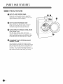 8
8
-
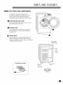 9
9
-
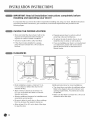 10
10
-
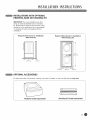 11
11
-
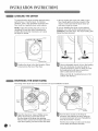 12
12
-
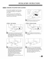 13
13
-
 14
14
-
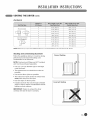 15
15
-
 16
16
-
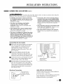 17
17
-
 18
18
-
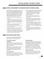 19
19
-
 20
20
-
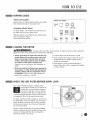 21
21
-
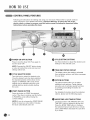 22
22
-
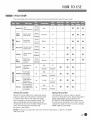 23
23
-
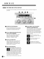 24
24
-
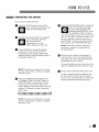 25
25
-
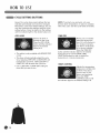 26
26
-
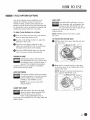 27
27
-
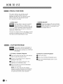 28
28
-
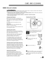 29
29
-
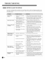 30
30
-
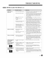 31
31
-
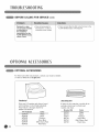 32
32
-
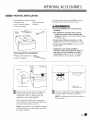 33
33
-
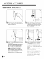 34
34
-
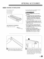 35
35
-
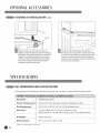 36
36
-
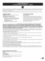 37
37
-
 38
38
-
 39
39
-
 40
40
-
 41
41
-
 42
42
-
 43
43
-
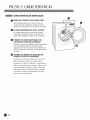 44
44
-
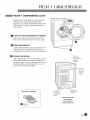 45
45
-
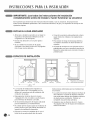 46
46
-
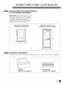 47
47
-
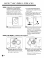 48
48
-
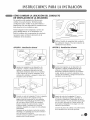 49
49
-
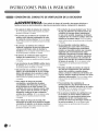 50
50
-
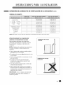 51
51
-
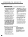 52
52
-
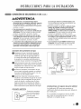 53
53
-
 54
54
-
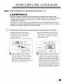 55
55
-
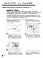 56
56
-
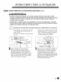 57
57
-
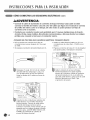 58
58
-
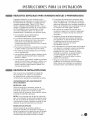 59
59
-
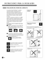 60
60
-
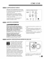 61
61
-
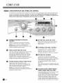 62
62
-
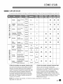 63
63
-
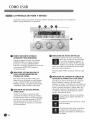 64
64
-
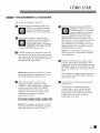 65
65
-
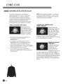 66
66
-
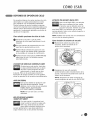 67
67
-
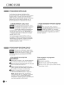 68
68
-
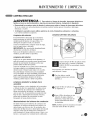 69
69
-
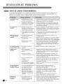 70
70
-
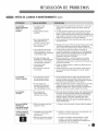 71
71
-
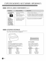 72
72
-
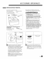 73
73
-
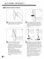 74
74
-
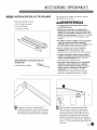 75
75
-
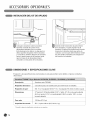 76
76
-
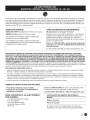 77
77
-
 78
78
-
 79
79
-
 80
80


LG DLG5966W El manual del propietario
- Categoría
- Secadoras de ropa eléctricas
- Tipo
- El manual del propietario
en otros idiomas
- English: LG DLG5966W Owner's manual
Artículos relacionados
-
LG DLE2601W El manual del propietario
-
-
LG DLGX2802W El manual del propietario
-
LG DLG1320W El manual del propietario
-
LG DLE2301W El manual del propietario
-
LG DLGX7188RM El manual del propietario
-
-
-
LG DLEY1701W El manual del propietario
-
LG DLEY1701WE El manual del propietario