Invacare LYNX LX-3 Unpacking And Setup Instructions
- Categoría
- Scooters
- Tipo
- Unpacking And Setup Instructions
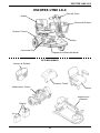
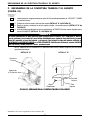
El Invacare LYNX LX-3 es un scooter eléctrico que puede ayudarte a desplazarte fácilmente. Tiene una cesta delantera para guardar tus pertenencias y una trasera para llevar objetos más pesados. El asiento es ajustable para mayor comodidad y el manillar es plegable para facilitar su transporte. El LYNX LX-3 también tiene un sistema de iluminación para que puedas conducirlo de forma segura incluso de noche.
El Invacare LYNX LX-3 es un scooter eléctrico que puede ayudarte a desplazarte fácilmente. Tiene una cesta delantera para guardar tus pertenencias y una trasera para llevar objetos más pesados. El asiento es ajustable para mayor comodidad y el manillar es plegable para facilitar su transporte. El LYNX LX-3 también tiene un sistema de iluminación para que puedas conducirlo de forma segura incluso de noche.


-
 1
1
-
 2
2
-
 3
3
-
 4
4
-
 5
5
-
 6
6
-
 7
7
-
 8
8
-
 9
9
-
 10
10
-
 11
11
-
 12
12
-
 13
13
-
 14
14
-
 15
15
-
 16
16
-
 17
17
-
 18
18
-
 19
19
-
 20
20
-
 21
21
-
 22
22
-
 23
23
-
 24
24
-
 25
25
-
 26
26
-
 27
27
-
 28
28


Invacare LYNX LX-3 Unpacking And Setup Instructions
- Categoría
- Scooters
- Tipo
- Unpacking And Setup Instructions
El Invacare LYNX LX-3 es un scooter eléctrico que puede ayudarte a desplazarte fácilmente. Tiene una cesta delantera para guardar tus pertenencias y una trasera para llevar objetos más pesados. El asiento es ajustable para mayor comodidad y el manillar es plegable para facilitar su transporte. El LYNX LX-3 también tiene un sistema de iluminación para que puedas conducirlo de forma segura incluso de noche.
en otros idiomas
- English: Invacare LYNX LX-3
Otros documentos
-
Sunrise Medical Ruby Manual de usuario
-
Pride Victory 10DX El manual del propietario
-
Pride Jazzy Zero Turn El manual del propietario
-
 Pride Mobility Travel Scooter Owner's Manual El manual del propietario
-
Pride FULL-SIZE 613 El manual del propietario
-
 Pride Mobility iRIDE S25 El manual del propietario
-
 Pride Mobility Mid-Size Scooter El manual del propietario
-
Razor E200 Series El manual del propietario
-
Honda FES150A S-wing El manual del propietario
-


