QSC Audio CXD4.5 Manual de usuario
- Categoría
- Mezcladores de audio
- Tipo
- Manual de usuario
Este manual también es adecuado para

CXD Amplifiers
User Manual
CXD4.2 — 4 Channel, 1600 W Amplifier
CXD4.3 — 4 Channel, 2500 W Amplifier
CXD4.5 — 4 Channel, 5000 W Amplifier
TD-000367-00-A
*TD-000367-00*

2
EN EN
TD-000367-00-A
EXPLANATION OF SYMBOLS
The term “WARNING!” indicates instructions regarding personal safety. If the instructions are not followed the result may be bodily injury or death.
The term “CAUTION!” indicates instructions regarding possible damage to physical equipment. If these instructions are not followed, it may result in
damage to the equipment that may not be covered under the warranty.
The term “IMPORTANT!” indicates instructions or information that are vital to the successful completion of the procedure.
The term "NOTE" is used to indicate additional useful information.
The intent of the lightning flash with arrowhead symbol in a triangle is to alert the user to the presence of un-insulated "dangerous"
voltage within the product's enclosure that may be of sufficient magnitude to constitute a risk of electric shock to humans.
The intent of the exclamation point within an equilateral triangle is to alert the user to the presence of important safety, and operating
and maintenance instructions in this manual.
IMPORTANT SAFETY INSTRUCTIONS
WARNING!:
TO PREVENT FIRE OR ELECTRIC SHOCK, DO NOT EXPOSE THIS EQUIPMENT TO RAIN OR MOISTURE.
• Keep these instructions.
• Heed all warnings.
• Follow all instructions.
• Do not use this apparatus near water.
• Clean only with a dry cloth.
• Do not block any ventilation opening. Install in accordance with the manufacturer's instructions.
• Do not install near any heat sources such as radiators, heat registers, stoves, or other apparatus (including amplifiers) that produce heat.
• Do not defeat the safety purpose of the polarized or grounding-type plug. A polarized plug has two blades with one wider than the other. A
grounding type plug has two blades and a third grounding prong. The wide blade or the third prong are provided for your safety. If the provided
plug does not fit into your outlet, consult an electrician for replacement of the obsolete outlet.
• Protect the power cord from being walked on or pinched particularly at plugs, convenience receptacles, and the point where they exit from
the apparatus.
• Only use attachments/accessories specified by the manufacturer.
• Unplug this apparatus during lightning storms or when unused for long periods of time.
• Refer all servicing to qualified service personnel. Servicing is required when the apparatus has been damaged in any way, such as power-supply
cord or plug is damaged, liquid has been spilled or objects have fallen into the apparatus, the apparatus has been exposed to rain or moisture,
does not operate normally, or has been dropped.
• The appliance coupler, or the AC Mains plug, is the AC mains disconnect device and shall remain readily operable after installation.
• Adhere to all applicable, local codes.
• Consult a licensed, professional engineer when any doubt or questions arise regarding a physical equipment installation.

3
EN EN
TD-000367-00-A
FCC Statement
NOTE:
This equipment has been tested and found to comply with the limits for a Class A digital device, pursuant to Part 15 of the FCC
Rules. These limits are designed to provide reasonable protection against harmful interference when the equipment is operated in a
commercial environment. This equipment generates, uses, and can radiate radio frequency energy and, if not installed and used in
accordance with the instruction manual, may cause harmful interference to radio communications. Operation of this equipment in a
residential area is likely to cause harmful interference in which case the user will be required to correct the interference at his
own expense.
RoHS STATEMENT
The QSC CXD4.2, CXD4.3 and CXD4.5 amplifiers are in compliance with European Directive 2002/95/EC – Restriction of Hazardous
Substances (RoHS).
The QSC CXD4.2, CXD4.3 and CXD4.5 amplifiers are in compliance with “China RoHS” directives. The following chart is provided for product use in
China and its territories:
QSC CXD4.2, CXD4.3, and CXD4.5 Amplifiers
部件名称
(Part Name)
有毒有害物质或元素
(Toxic or hazardous Substances and Elements)
铅
(Pb)
汞
(Hg)
镉
(Cd)
六价铬
(Cr(vi))
多溴联苯
(PBB)
多溴二苯醚
(PBDE)
电路板组件
(PCB Assemblies)
X O O O O O
机壳装配件
(Chassis Assemblies)
X O O O O O
O: 表明这些有毒或有害物质在部件使用的同类材料中的含量是在 SJ/T11363_2006 极限的要求之下。
(O: Indicates that this toxic or hazardous substance contained in all of the homogeneous materials for this part is below the limit requirement
in SJ/T11363_2006.)
X: 表明这些有毒或有害物质在部件使用的同类材料中至少有一种含量是在 SJ/T11363_2006 极限的要求之上。
(X: Indicates that this toxic or hazardous substance contained in at least one of the homogeneous materials used for this part is above the
limit requirement in SJ/T11363_2006.)

4
EN EN
TD-000367-00-A
Warranty (USA only; other countries, see your dealer or distributor)
QSC Audio Products 3 Year Limited Warranty
QSC Audio Products, LLC (”QSC”) guarantees its products to be free from defective material and/or workmanship and will replace defective parts
and repair malfunctioning products under this warranty when the defect occurs under normal installation and use, provided the unit is returned to
our factory, one of our authorized service stations or an authorized QSC International Distributor via pre-paid transportation with a copy of proof
of purchase (i.e., sales receipt). This warranty provides that the examination of the return product must indicate, in our judgment, a manufacturing
defect. This warranty does not extend to any product which has been subjected to misuse, neglect, accident, improper installation, or where the
date code has been removed or defaced. QSC shall not be liable for incidental and/or consequential damages. This warranty gives you specific legal
rights. This limited warranty is freely transferable during the term of the warranty period. The warranty on QSC products is NOT VALID if the products
have been purchased from an unauthorized dealer/online e-tailer, or if the original factory serial number has been removed, defaced, or replaced in
any way. Damage to, or loss of any software or data residing on the product is not covered. When providing repair or replacement service, QSC will
use reasonable efforts to reinstall the product’s original software configuration and subsequent update releases, but will not provide any recovery or
transfer of software or data contained on the serviced unit not originally included in the product.
Customers may have additional rights, which vary from state to state or from country to country. In the event that a provision of this limited warranty is
void, prohibited or superseded by local laws, the remaining provisions shall remain in effect.
The QSC limited warranty is valid for a period of three (3) years from date of purchase in the United States and many (but not all)
other countries.
For QSC warranty information in countries other than the United States, contact your authorized QSC international distributor. A list of QSC
International distributors is available at www.qsc.com.
To register your QSC product online, go to www.qsc.com and select ”Product Registration”. Other questions regarding this warranty can be answered
by calling, e-mailing or contacting your authorized QSC distributor.
Phone: 1-800-854-4079 within US and Canada, +1-714-754-6175 international, Email: [email protected], Website: www.qsc.com.

5
EN EN
TD-000367-00-A
Introduction
Built for system integrators, the CXD series amplifiers provide multi-channel amplification with built-in DSP and enough power to drive wide varieties
of speaker systems with optimal energy efficiency. The CXD Series consists of three light-weight, 2RU, four-channel amplifiers with on-board DSP and
flexible channel combining as well as 70V and 100V direct drive. These amplifiers not only provide the power and processing to make your system
perform better, they offer outstanding efficiency ensuring that energy costs are kept to a minimum over the life of the installation.
CXD amplifiers feature Flexible Amplifier Summing Technology (FAST). Depending on the model, 1600, 2500, or 5000 Watts of total power can be
distributed across one to four outputs. In addition, the CXD4.3 and CXD4.5, can drive 70V or 100V speaker lines directly from any one or all of the four
outputs. This flexibility allows CXD Series amplifiers to drive (for example) two full-range, surface-mounted loudspeakers along with a subwoofer and
one 100 V distributed loudspeaker line; or a high-power subwoofer and a bi-amplified full-range loudspeaker; three 70V distributed loudspeaker lines
and a subwoofer; or a single very high-power channel to drive monster subwoofers.
The CXD Series amplifiers use QSC’s third-generation class-D power amp design in combination with a custom power stage utilizing a new output
device. In addition, CXD amplifiers employ the proven PowerLight power supply in conjunction with Power Factor Correction (PFC) which aligns the
current waveform with the AC mains voltage waveform. PFC enables the CXD Series amplifiers to draw current from the wall in a more efficient and
controlled manner resulting in very high power from a single standard AC breaker. Additionally, the CXD Series amplifiers offer multi-stage sleep
modes saving energy when possible without sacrificing performance. The result is an exceptionally powerful and flexible platform that offers low
weight and efficiency.
With four channels of amplification plus signal processing in just 2RUs, the CXD series replaces equipment taking up as much as three times
the rack-space.
A single CXD Series amplifier is a capable and sophisticated loudspeaker processor. Integration of processing and amplification means that the DSP
knows exactly what the amplifier is doing so dynamics processing can be far more accurate and effective. This approach employs both RMS and Peak
Limiters that allow the amplifier and loudspeaker to produce more output without being pushed to distortion or destruction.
The on-board DSP offers four channels of cross-over filters, parametric EQ/Low-shelf/High-shelf, alignment delay and dynamics processing —
everything needed to optimize a loudspeaker system. Additionally when using QSC loudspeakers, CXD amplifiers provide Intrinsic Correction™, a
combination of filtering, limiting and loudspeaker knowhow that was first developed for QSC's WideLine line-array loudspeakers. Intrinsic Correction
compensates for the non-linearity in array and horn design resulting in exceptional performance.
The CXD also includes manufacturers' recommended tunings for the most popular passive loudspeakers. A system setup wizard helps you select the
right preset, or select one of the 20 configuration templates and create tunings that you can save in the user preset library.
With a dedicated front panel user interface, complete with LED meters and indicators, a 400 x 240 TFT color display, a rotary encoder and navigation
buttons, the CXD amplifiers provide an intuitive means to control the system.
Unpacking
There are no special unpacking instructions. You may want to keep the shipping material for the unlikely event that the amplifier should need
returning for service.
Package Contents
1. Quick-Start Guide TD-000350-00
2. Warning Information Sheet TD-000420-00
3. CXD Amplifier
4. IEC AC Power Cord
5. Euro-style Connector Plug, 3-pin (4)
6. Euro-style Connector Plug, 8-pin (1)
7. Euro-style Connector Plug, 3.5 mm, 2-pin (1)
8. Euro-style Connector Plug, 3.5 mm, 3-pin (1)
9. USB Cable (1)

6
EN EN
TD-000367-00-A
Features
Amplifier Front Panel
— Figure 1 —
1
2
3
4
5
6
7
8
12
13
14
15
16
9
10
11
1. Output channels are labeled A, B, C, and D
2. Output Channel Mute Buttons and LEDs (Red)
3. Output Channel Limiter LEDs (Red)
4. Output Channel -10 dB Below Limiter Activation LEDs (Blue)
5. Output Channel -20 dB Below Clip LEDs (Blue)
6. Soft Power Button (Blue/Red)
7. Channel Select Buttons and LEDs (Amber for Input, Blue for Output)
8. Input Channel Clip LEDs (Red)
9. Input Channel Signal-Present LEDs (Blue)
10. Input channels are labeled 1, 2, 3, and 4
11. LCD Graphic Display
12. HOME Button
13. ENTER Button
14. MASTER CONTROL Knob
15. EXIT Button
16. GAIN Button
Amplifier Rear Panel
NOTE:
The CXD4.3, and CXD4.5 models have a different rear panel configuration than the CXD4.2 rear panel. The difference is that the
position of the fan and the eight-pin Euro-style connector and associated information are interchanged.
— Figure 2 —
CH AB
T1+
T3+
T2-
T4-
CH CD
T5+
T7+
T6-
T8-
CH ABC
T1
+
T3+
T5+
T2-
T4-
T6-
CH ABCD
T1
+
T3+
T5+
T7+
T2-
T4-
T6-
T8-
CH AB+CD
T1
+
T3+
T5-
T7-
CH C
+
D
T5+
T7-
CH A
+
B
T1+ T3-
BRIDGED
OUTPUTS TO SPEAKERS
CH A
CH D
CH C
CH B
+
+
+
+
-
-
-
-
T1
T4
T3
T2
T5
T8
T7
T6
SETTINGS CAN BE
CONFIGURED FOR
70V, 100V AND
200V DIRECT
OUTPUT.
PARALLEL CHANNEL
COMBINING APPLICATIONS
THIS PRODUCT SHOULD BE SUPPORTED ON ALL
FOUR CORNERS WHEN INSTALLED IN A RACK
USB
HEARTBEAT
GPO
GPI
1 4 5 6 7 8 102 93
1. USB Type B, four-pin
2. GPO/Heartbeat (output) Euro-style Connector, 3-pin
3. GPI (input) Euro-style Connector, 2-pin
4. Four three-pin Euro-style Connectors
5. One eight-pin Euro-style Loudspeaker Connector
6. Cooling fan
7. AC Power Switch
8. Locking IEC Power Connection
9. Rear Rack-mount Bracket (CXD4.3 and CXD4.5)
10. Front Rack-mount Brackets

7
EN EN
TD-000367-00-A
Amplifier Control
— Figure 3 —
OUTPUT
HOME
MASTER
CONTROL
-10
-20
LIM
SEL
MUTE
A
1
SEL
MUTE
B
2
SEL
MUTE
C
3
SEL
MUTE
D
4
CLIP
SIG
INPUT
ENTER
EXIT
GAIN
Off Mode
• Rear power switch is off, the amplifier is not operable. The power
switch is the AC Mains disconnect.
• The power button is not illuminated.
• Turn the power switch to on. The amplifier enters the mode it was in
when power was removed. The power button is illuminated based on
the mode.
• If GPI is enabled, the Off Mode button is disabled.
Run Mode
• From Standby or Mute All modes, press and release the power button
on the front panel.
• The power button is illuminated blue.
• The amplifier is fully operable; audio can pass.
• If GPI is enabled, the Run Mode button is disabled.
Standby Mode
• From Mute All or Run modes, press and hold the power button on
the front panel for two to three seconds.
• The power button illuminates solid red.
• The front panel LCD is off.
• The amplifier is not operable; audio will not pass.
• If GPI is enabled, the Standby Mode button is disabled.
Mute All Mode
• From the Run Mode, quickly press and release the power button.
• The power button flashes red.
• The outputs are muted and amplifiers are off.
• The front panel and DSP functionality are fully operable. Any changes
you make are saved and take effect in the Run Mode.
• If GPI is enabled, the Mute All Mode button is disabled.
Master Control Knob
• Scrolls up/down and right/left to select menu items and parameters
• Adjusts parameters
ENTER Button
• Navigates into the menu structure
• Enters the edit mode for adjusting parameters
• Confirms the changes you make, and exits the edit mode.
EXIT Button
• Navigates out of the menu structure and parameter selection.
• In the edit mode, pressing EXIT reverts the value back to its prior
state, and exits the edit mode.
HOME Button
• If you are on the Home screen, pressing HOME displays the alternate
Home screen. Pressing HOME again returns you to the primary
Home screen.
• If you are on a navigation screen, pressing HOME takes you to the
home screen.
• If you are on an edit screen, pressing HOME will confirm any value
being edited and take you to the Home screen.
GAIN Button
• Pressing the GAIN button from any screen takes you to the output
gain screen for the most recently accessed output channel.
• Pressing GAIN again confirms the gain change and returns to the
screen you were on when you pressed GAIN.
• The Gain button illuminates green when selected.
SEL Buttons
• Use these buttons to navigate between input channels or output
channels. For example, if you are adjusting output gain on channel A,
pressing the channel B SEL button takes you to the gain adjustment
for channel B.
• The SEL buttons are active only when the LCD screen is on an input
or output parameter adjustment screen.
• The SEL buttons illuminate blue for output channels, and amber for
input channels.
LIM LEDs
• Illuminates red when the Limiter is engaged.
-10 and -20 LEDs
• Indicates the output level of the channel.
CLIP LEDs
• Illuminates red when the input signal is being clipped.
SIG LEDs
• Illuminates blue when a signal is present.
ENTER
EXIT
HOME
GAIN GAIN
SEL SEL
LIM
-10 & -20
CLIP
SIG

8
EN EN
TD-000367-00-A
CXD Amplifier Signal Flow
Screen Types
— Figure 5 —
Informational
Informational screens, like the HOME screen, are
designed to provide you with a good amount of
useful information at a glance.
F1: A B C D
Full
+1.5 dB
A - FR
+1.5 dB
C - FR
Full
+1.5 dB
D - FR
Full
121 V 7.2 AAC Voltage: AC Current:
Home (Press HOME for more information)
+3.5 dB
B - FR
Full
Amp Status:
OK
Preset # and Configuration
Location and breadcrumbs
Channel Configuration
and Gain
AC Voltage and Current
Amplifier Status
— Figure 6 —
Preset Recall and Save
Menu
PRESETS
INPUT S
F1: A B C D
Preset # and Configuration
Location and breadcrumbs
Current Menu Selection
Empty area indicates no
selections above (CCW).
Next Menu selection below
(CW)
Navigational
Navigational screens provide the means to move
around and select menu items. Use the Master
Control knob, ENTER and EXIT buttons for navigation.
This is an example of one type of navigational screen,
there are others.
— Figure 7 —
Parameter Editing
Parameter editing screens allow you to select, edit,
and confirm changes for various system parameters.
Use the ENTER button to edit and confirm changes
to parameters. Use the Master Control knob to select
parameter, and make adjustments. Use the EXIT
button to exit the edit mode without saving changes.
Gain
-7.0 dB
Gn/Pol
F1: A B C D
Polarity
POL+
Output
A
20 dB
-60 dB
Gain
-7.0 dB
Parameter being edited
Parameter not selected
Parameter selected
— Figure 4 —
Input Settings Output Processing
Gain
Gain
Gain
Gain
1
4
3
2
Mute
Mute
Mute
Mute
Gain /
Polarity
Gain /
Polarity
Gain /
Polarity
Gain /
Polarity
Low-
pass
Filter
Mixer
Mixer
Mixer
Mixer
Sensitivity
Switch
Sensitivity
Switch
Sensitivity
Switch
Sensitivity
Switch
Sensitivity
Switch
Sensitivity
Switch
A/D
A/D
A/D
A/D
Meter
Meter
Meter
Meter
5-Band
PEQ
5-Band
PEQ
5-Band
PEQ
5-Band
PEQ
Delay
Delay
Delay
Delay
Meter
Meter
Meter
Meter
D/A
D/A
D/A
D/A
Crossover
Button
Actuated
Amp Config.
A
D
B
C
Set by
Preset or Wizzard
RMS
Peak
Limiter
RMS
Peak
Limiter
RMS
Peak
Limiter
RMS
Peak
Limiter
Low-
pass
Filter
Low-
pass
Filter
Low-
pass
Filter
High-
pass
Filter
High-
pass
Filter
High-
pass
Filter
High-
pass
Filter

9
EN EN
TD-000367-00-A
Menu Tree
*For QSC Line Arrays only
Presets
Preset Wizard
Preset Recall
Preset Save
Inputs
Input Sensitivity
Input Gain
Outputs
Mixer w/Noise & Tone
Mode (Lo-Z, 70V, 100V)
Save Speaker
Load Speaker
Array Correction*
Limiter
Delay
PEQ
Crossover
Spkr Processing
Utilities
Display
Status
Amp ID
Password
Lockout
GPIO
About Presets
The CXD amplifiers are preset driven. In order to get the most out of the amplifiers, an understanding of how presets work is essential. A Preset, in the
context of the CXD amplifiers, is a combination of amplifier configuration (inputs and outputs), DSP and loudspeaker assignments. When a preset is
recalled it can change the output routing and wiring and/or any of the DSP settings.
The CXD amplifiers come with 20 unchangeable factory presets, and 50 user-defined presets. The factory presets are designed to be starting points
for creating the presets you need for your particular installation. Factory presets F1: thru F9: have no DSP or loudspeaker assignments, only output
configurations. Factory presets F10: thru F20: include basic settings along with the output configurations.
Creating User-defined Presets
A preset can be created in two ways, the first is to modify an existing preset, then save this as a new preset. The second is to use the Preset Wizard to
create a Preset from scratch.
Save As a New Preset
After selecting a starting preset, navigate through the Input and Output menus to select and modify the parameters needed for your system. After
modifying the parameters for each channel, return to the Preset menu and save your work. If you started with a user-defined preset, you can update
the preset you started with using the SAVE function or, you can use the SAVE AS function.
Preset Wizard
The Preset Wizard simplifies the preset creation process, and allows you to create a preset from the ground up. The Preset Wizard provides a
mechanism for you to select the desired power and load. Based on these selections, the best amplifier configuration is selected and you are then
allowed to select and assign loudspeakers to each output.
NOTE:
By default, all 50 of the user-defined presets are configured the same as factory preset F1. Either method described above
"overwrites" some existing preset. The main difference is the SAVE function overwrites only the preset number you started with, and the
SAVE AS function allows you to save to a different user preset number and change the name.

10
EN EN
TD-000367-00-A
Installation
The following steps are written in the recommended installation order.
Mount the CXD Amplifier
The CXD Series amplifiers are designed to be mounted in a standard rack-mount unit.
The amplifiers are 2RU high, the CXD4.3 and CXD4.5 are 381 mm (15 in) deep, the
CXD4.2 is 229 mm (9 in) deep.
Depending on the depth of your rack, the Rear Rack Ear Support kit (FG-000031-00)
may be required for rack mounting. Refer to http://qsc.com/products/ under
Accessories for details.
CAUTION!:
Be sure that nothing is blocking the front or rear
ventilation openings, and that each side has a minimum of
2 cm clearance.
1. Use the proper fastening hardware (not included) to secure the amplifier in the rack. The CXD4.3 and CXD4.5 have four front and four rear
mounting tabs. The CXD4.2 has four front mounting tabs.
AC Mains
WARNING!:
When the AC Power is on, there is a potential of having
dangerous voltage at the output terminals on the rear of the amplifier. Use
caution not to touch these contacts. Turn off the AC Mains disconnect switch
prior to making any connections.
The CXD amplifiers have a Universal power supply 100 – 240 VAC, 50 – 60 Hz, with an IEC
locking connector.
1. Connect the IEC AC cable between the amplifier rear AC connector and the AC source.
AC Power
NOTE:
If the amplifier has no audio for fifteen minutes, the amplifier stops switching. The amplifier returns to the Run mode the instant audio is
present.”
When you remove power from the amplifier, then re-apply the power, the amplifier returns to its last state.
— Figure 8 —
— Figure 9 —

11
EN EN
TD-000367-00-A
Inputs
Connect the Audio Inputs
— Figure 10 —
HEARTBEAT
GPO
GPI
USB
ROUTABLE INPUTS
21 43
— Figure 11 —
Unbalanced
— Figure 12 —
Balanced
There are four three-pin Euro-style connectors labeled 1 through 4 providing the audio inputs on the CXD Amplifiers. A single input can be mixed to
one or a combination of outputs. You can use from one to four of the inputs. The inputs
are 10 kΩ balanced or unbalanced, with a sensitivity of either +4 or +14 dBu.
1. Make sure your audio source devices are powered off.
2. Connect the input source wires to the Euro-style connectors as shown. (Figure 11 and
Figure 12)
3. The CXD Series has the capability of routing the inputs to different outputs. Be sure that
the connections you make here match the configuration of the amplifier.
4. Plug the Euro-style audio connectors into the appropriate inputs on the rear of
the amplifier.
USB (Optional)
The USB cable (supplied) connects to a Mac or PC for use with the Amplifier Navigator
software. You can update the amplifier firmware, save and deploy configuration files, and
more. Refer to the Amplifier Navigator online help for details.
GPIO/Heartbeat
There are two 3.5 mm Euro-style connectors on the rear of the amplifier.
• Heartbeat — The heartbeat output supplies a square wave signal of 1 Hz @ 3.3 V. This signal can connect to a life-safety system to monitor the
go/no-go condition of the amplifier. The amplifier must be completely incapable of producing output for the heartbeat signal to stop. A missing
heartbeat alerts the life-safety system of the disabled condition. A user-initiated condition such as muting the outputs, placing the amplifier in
Standby mode, or placing the amplifier in Mute All mode, does not stop the heartbeat.
• GPO — The functionality of this general purpose output pin has not been determined as of the release of this document.
• GPI — This input is used to put the amplifier into Standby from a remote location. When the GPI is enabled in the Utilities menu, then is shorted to
ground, the amplifier goes into the Standby mode. The front-panel power button is disabled when GPI is enabled.
— Figure 13 —
+
-
+
-
+
-
+
-

12
EN EN
TD-000367-00-A
Outputs
The CXD amplifiers have four configurable outputs. You can set the power, combine outputs (bridged and parallel), and adjust the DSP for each
output. When the output configuration of the amplifier changes, the output terminals, controlled by relays, change accordingly. Use the diagrams
shown in Figure 15 thru Figure 23 as a reference for wiring the loudspeakers.
Select the Output Configuration
The first step in configuring your amplifier is to select a Preset based on the loudspeakers being connected to the amplifier. You can use a factory
preset, and then adjust the parameters as needed, then save the configuration as a user-defined preset. In addition, you can use the "Preset Wizard"
on page 16 to create presets from the ground up. When the configuration is changed, all four channels are automatically muted.
— Figure 14 —
F1: A B C D
F7: ABC D
M
ABC
M
D
Input number
Sub-woofer
Mid-Frequency
Full Range
High-Frequency
Low-Frequency
Current Configuration
Selected Configuration
Input Mixer
Output Configuration
Frequency Range color
Frequency Range Color Codes
WARNING!:
When the AC Power is on, there is a potential of having dangerous voltage at the output terminals on the rear of
the amplifier. Use caution not to touch these contacts. Turn off the AC Mains disconnect switch prior to making any connections.
IMPORTANT:
QSC recommends that you connect jumpers between the output terminals where the terminals are the same points
electrically. When configuring your amplifier, there are going to be some loudspeaker connections that are noted as being "electrically
the same point". In Figure 15, all four channels are in parallel with the "electrically the same" terminals jumpered as recommended. In
addition, you can connect one loudspeaker to each of the four output channel terminals, and the four loudspeakers are in parallel; in this
case you would not need to jumper the terminals. You can connect four loudspeakers to one channel's output terminals (i.e. T1 and T2),
and the four loudspeakers are in parallel; in this case you would want to jumper the terminals. In all of the examples below, the
"electrically the same" terminals are shown with jumpers installed.
1. Turn the AC Mains power switch on the back of the amplifier to on. The amplifier starts in the Run mode.
2. Press and release the front-panel power button. The button flashes red, the amplifier is in Mute All mode.
3. Select the configuration appropriate for your loudspeakers, using either Preset Recall, or the Preset Wizard.
The following is a list of configurations for 1, 2, 3, and 4-channel outputs. This is not an exhaustive list, but is intended to give you an idea of what is
available and how the outputs would be wired.
One-Channel Configurations
— Figure 15 —
F9: ABCD
F9: ABCD
ABCD Parallel
M
ABCD
The following are electrically
the same point
T1+, T3+, T5+, and T7+
T2-, T4-, T6-, and T8-

13
EN EN
TD-000367-00-A
— Figure 16 —
F8: AB+CD
F8: AB+CD
AB Parallel
Bridged with
CD Parallel
The following are electrically
the same point
T1+and T3+
T5- and T7-
M
AB+CD
Two-Channel Configurations
— Figure 17 —
F6: A+B C+D
F6: A+B C+D
A+B Bridged
C+D Bridged
A+B
C+D
M M
— Figure 18 —
F5: AB C+D
F5: AB C+D
AB Parallel
C+D Bridged
AB
C+D
M M
The following are electrically
the same point
T1+ and T3+
T2- and T4-
— Figure 19 —
F4: AB CD
F4: AB CD
The following are electrically
the same point
T1+ and T3+
T5+ and T7+
T2- and T4-
T6- and t8-
AB Parallel
CD Parallel
AB
CD
M M

14
EN EN
TD-000367-00-A
— Figure 20 —
F7: ABC D
F7: ABC D
ABC
D
M M
The following are electrically
the same point
T1+, T3+, and T5+
T2-, T4-, and T6-
ABC Parallel
D Single
Three-Channel Configurations
— Figure 21 —
F3: A+B C D
F3: A+B C D
A+B Bridged
C Single
D Single
A+B C D
M M M
— Figure 22 —
F2: AB C D
F2: AB C D
AB Parallel
C Single
D Single
M
AB
M
C
M
D
The following are electrically
the same point
T1+ and T3+
T2- and T4-
Four-Channel Configuration
— Figure 23 —
F1: A B C D
F1: A B C D
A Single
B Single
C Single
D Single
M M
A B
M
C
M
D

15
EN EN
TD-000367-00-A
Connect the Loudspeakers
WARNING!:
When the AC Power is on, there is a potential of having
dangerous voltage at the output terminals on the rear of the amplifier. Use
caution to not touch these contacts. Turn off the AC Mains disconnect switch
prior to making any connections.
1. Turn the AC Mains power switch, on the back of the amplifier, to OFF.
2. Connect the loudspeaker wiring to the 8-pin Euro-style connector. Refer to Figure 15
thru Figure 23. When combining channels, QSC recommends that you connect jumpers
between the electrically same output terminals. Refer to Figure 15 and the WARNING
above the figure.
3. Install the Euro-style connector onto the rear of the amplifier as shown in Figure 24.
4. Use a Phillips screwdriver to secure the connector.
AC Power On
After connecting the outputs to the loudspeakers, you may turn the amplifier on.
1. Make sure the output gain settings for all audio-source devices (CD Players, Mixers, Instruments, etc.) at the lowest output (max attenuation).
2. Turn on all audio sources.
3. Turn the AC Mains power switch on the back of the amplifier to ON. The amplifier starts in the state it was in when power was removed.
4. You can now bring up the outputs of your audio sources.
Power Distribution Charts
The following charts show the maximum power output for each channel in each configuration, and under different loads.
CXD 4.3 — Total Power: 2500W
8Ω Load 4Ω Load 2Ω Load
Configuration
A B C D A B C D A B C D
4 CH (A B C D) 625 625 625 625 650 650 650 650 600 600 600 600
3 CH (AB C D) 1000 625 625 1200 650 650 1200 600 600
3 CH (A+B C D) 1250 625 625 1150 650 650 625 600 600
2 CH (AB CD) 1000 1000 1200 1200 1200 1200
2 CH (AB C+D) 1000 1250 1200 1150 1200 625
2 CH (A+B C+D) 1250 1250 1150 1150 625 625
2 CH Alt (ABC D) 1100 625 2000 650 2500 600
1 CH (ABCD) 1100 2100 2500
1 CH (AB+CD) 2500 2370 2230
— Table 1 —
CXD 4.5 — Total Power: 5000W
8Ω Load 4Ω Load 2Ω Load
Configuration A B C D A B C D A B C D
4 CH (A B C D) 1150 1150 1150 1150 1250 1250 1250 1250 625 625 625 625
3 CH (AB C D) 1200 1150 1150 2250 1250 1250 2100 625 625
3 CH (A+B C D) 2250 1150 1150 1150 1250 1250 625 625 625
2 CH (AB CD) 1200 1200 2250 2250 2100 2100
2 CH (AB C+D) 1200 2250 2250 1150 2100 625
2 CH (A+B C+D) 2250 2250 1150 1150 625 625
2 CH Alt (ABC D) 1150 1150 2400 1250 4100 625
1 CH (ABCD) 1150 2300 4200
1 CH (AB+CD) 4200 4250 2250
— Table 2 —
— Figure 24 —

16
EN EN
TD-000367-00-A
Preset Wizard
NOTE:
The power levels shown in this procedure are taken from the CXD4.3 unless indicated otherwise. CXD4.2 will show less power
and CXD4.5 will show greater power. For complete details refer to the "Specifications" on page 28.
HOME > PRESETS > PRESET WIZARD > ENTER
Step 1 —
Adjust Impedance and Power
OUTPUTS SPEAKERS SAVE
A B C D
Output:
8.0 - - - - - -
Imped:
625 - - - - - -
Power:
Remaining Power Available: 1875 W
Enter Load Profile (Impedance and Power)
Default = 8 Ω
Default = min. for amp
Adjust Impedance based on
the total loudspeaker load
connected to the channel.
Scroll to select (Imped or Power)
To edit, press
ENTER
Repeat for remaining
output channels
To confirm, press
ENTER
Turn to adjust parameter
Impedance and Power
are dynamically linked
for adjustments.
— Figure 25 —
Possible Output Mode Combinations using the Preset Wizard
Modes: A B = Separate Channels / A+B = Bridge Mode / AB = Parallel Mode
* Precentages are used to represent the power for different amplifier models.
- - -
B
25%
A
- - -
25%
D
- - -
25%
C
- - -
25%
AB
- - -
50%
D
- - -
25%
C
- - -
25%
CD
- - -
50%
AB
- - -
50%
A+B
- - -
50%
D
- - -
25%
C
- - -
25%
D
- - -
25%
ABC
- - -
75%
ABCD
- - -
100%
AB + CD
- - -
100%
A+B
- - -
50%
C+D
- - -
50%
*
Step 2 —
Select Output Channel for Speaker Assignment
OUTPUTS SPEAKERS SAVE
Assign
AssignAssign
Output:
A DCB
Imped:
8.0 8.08.08.0
Spkr:
- - - - - - - -- - - -- - - -
Assign
Power:
625 625625625
Loudspeaker assignment is optional,
you can assign a loudspeaker to one
or more channels, or none at all.
When you are finished setting
the Impedance and Power for
each output, continue to scroll
to access the SPEAKERS tab.
To Assign a loudspeaker, press
Continue to Step 3.
Scroll to select Output channel
ENTER
Step 3 —
Select Speaker Type for Channel
OUTPUTS SPEAKERS SAVE
Output:
A
ASSIGN
2-Way LF
Speaker:
80 Hz
Band:
WL2102 BiLFNS
Filter:
Scroll to select a Speaker model
To edit Speaker, press
ENTER
Scroll to select (Band, Filter)
To confirm, press
ENTER
Turn to adjust parameter
ENTER
To edit, press
To confirm, press
ENTER
Band and Filter
selections are based on
the Speaker you select.
You must select a
loudspeaker before
selecting Band and Filter.
Scroll to select ASSIGN
ENTER
To assign the speaker to the output channel, press

17
EN EN
TD-000367-00-A
Step 4 —
Save Wizard Preset
Edit preset number or press EXIT
User Preset Number:
21
SAVE
New Preset Name
C o n f i g - A
OUTPUTS SPEAKERS SAVE
Scroll to the Save screen
To edit User Preset number, press
ENTER
When you have finished
selecting loudspeakers,
continue to scroll to
access the SAVE tab.
Turn to adjust parameter
To confirm, press
ENTER
Create New Preset from an Existing Preset
To create a preset from an existing preset, recall the preset with the desired output configuration, modify the Input parameters, Output parameters,
then save the preset. In addition, you can save the preset as you are going thru the creation process.
Recall a Preset
A Preset includes the output configuration, input parameters, and loudspeaker profiles (DSP, load, and assignments). There are 20 factory presets
that can be recalled, but not overwritten. Factory presets F1: Config thru F9: Config contain output configurations only. Factory presets F10: thru F20:
contain the output configurations and basic DSP for the configurations. There are 50 user presets that can be recalled and overwritten.
HOME > PRESETS > PRESET RECALL > ENTER
Step 1 —
Select Preset
A B C D
M M M M
F1: A B C D
F1: A B C D
Indicates more Presets
Input Sub MF FullHFLF
Scroll to desired Preset
20 Factory, 50 User-defined
Step 2 —
Confirm Selection
F1: A B C D
F18: 3-Way
Press ENTER to confirm selection
A+B
C D
M M M
The message at the bottom changes to: “Recalling Preset now...”
You may hear relays clicking
To conrm the selection, press
ENTER
To select the Preset conguration, press
ENTER

18
EN EN
TD-000367-00-A
Set up the Inputs
NOTE:
Changes made to input levels are in real time.
HOME > INPUTS > INPUT SENS > ENTER
Step 1 —
Select Input Sensitivity
F1: A B C D
Inputs > Input Sens
INPUT SENS +14 dBu
Press ENTER to confirm
Input
1
Scroll to select (+14 or +4 dBu)
(The background turns to green.)
To confirm selection, press
ENTER
SEL
To move to the next input, press
Repeat procedure for
remaining input channels.
HOME > INPUTS > INPUT GAIN > ENTER
Step 2 —
Set Input Gain
F1: A B C D
Inputs > Input Gain
INPUT GAIN -11.8 dB
Press ENTER to confirm
Input
1
Scroll to select (-100 thru 20 dB)
(0.1 dB increments)
ENTER
To confirm selection, press
SEL
To move to the next input, press
Repeat procedure for
remaining input channels.
Set up the Outputs
NOTE:
Changes made to outputs are in real time.
Mixer
The CXD amplifiers are equipped with an internal mixer that allows you to
adjust the signals from each input to each of the four outputs. Figure 26 is a
diagram of the Mixer for Output Channel A.
• The default setting for the Input Gain is 0.0 dB, and is set in the
INPUTS section.
• Each output channel has four inputs, each controlled by a Mixer Gain.
• The Input Gain and Mixer Gain are cumulative. For example, if you set the
Input Gain to +2.0 dB, and the Mixer Gain to -5.0 dB, the resulting output
is -3.0 dB
As a default one channel is mixed to each output: 1 - A, 2 - B, 3 - C, 4 - D, all
other input channels are set to -100. Adjusting an Input Gain changes that
channel's input to the mixers of all channels. Changing a Mixer Gain affects only
that input for the selected output channel.
— Figure 26 —
Input 1
Input 2
Input 3
Input 4
Output
A
Output Mixers
B
D
C
Output Mixers
B
D
C
Output Mixers
B
D
C
Output Mixers
B
D
C
INPUTS OUTPUT
MIXER A
0.0 dB
-100 dB
-100 dB
-100 dB
0.0 dB
0.0 dB
0.0 dB
0.0 dB

19
EN EN
TD-000367-00-A
HOME > OUTPUTS > MIXER > ENTER
Step 1 —
Set Mixer Gains
F1: A B C D
Output
A
MIXER
Adjust the Mixer Gain for the selected Input
After confirming all settings, press
EXIT
To confirm, press
ENTER
Scroll to remaining Inputs and repeat
Input 1
4.2
Input 2
-100.0
Input 3
2.7
Input 4
-100.0
SEL
To move to the next output, press
Mode Select
HOME > OUTPUTS > MODE > ENTER
Step 2 —
Select the Output Mode
F1: A B C D
Outputs > Mode
MODE SELECT Mode:
Press ENTER to confirm
Output
A
Low-Z, 70V, 100V
Low-Z
Scroll to select Low-Z, 100V, or 70V
ENTER
To confirm selection, press
Loudspeaker Processing
The Speaker Processing section allows you to make adjustments to the Crossover, EQ, Delay, Limiter, and QSC Array details for each output channel.
In addition, you can load a pre-defined loudspeaker then make any adjustments needed, and save the changes as a user-defined loudspeaker.
Depending on the loudspeaker selection, various parameters are not available for adjustment. When you make adjustments, you are making them in
real time. If audio is passed while making changes, it is affected by the change.
The following instructions are not all in menu order, and all are optional. Repeat the following procedure for each output channel as necessary.
Load Speaker Profile
A loudspeaker profile includes all the DSP and loudspeaker characteristics available in the SPKR PROC section. When you LOAD a loudspeaker, you
are loading all of the DSP and characteristics of that loudspeaker. You can start by loading a loudspeaker and then make modifications and save your
new profile, or you can build the profile without loading a loudspeaker, and then save it as a new profile. If you load a QSC loudspeaker, the amplifier
is set for that specific loudspeaker and some parameters may be locked out because they are set to their optimal value by the Intrinsic Correction
Calculator, and should not be adjusted. The CXD comes with a number of supported loudspeakers from other manufacturers. Refer to the list under
"Supported Loudspeakers" on page 27. There may be additions to this list in the futrue that can be loaded with firmware updates.
NOTE:
If you make changes to any of the loudspeaker processing parameters, and then LOAD a loudspeaker profile, all the changes
you made are overwritten.

20
EN EN
TD-000367-00-A
HOME > OUTPUTS > SPKR PROC > LOAD SPKR > ENTER
Step 1 —
Load an Existing Loudspeaker for the Selected Output
ABOUT SPEAKERS LOAD
Output:
A
CONFIRM
2-Way LF
Speaker:
80 Hz
Band:
WL2102 BiLFNS
Filter:
Band and Filter
selections are
displayed and
constrained based
on the loudspeaker.
Scroll to select Speaker model
To edit Speaker, press
ENTER
Scroll to (Band, Filter)
To confirm, press
ENTER
Adjust selected parameter
ENTER
To adjust, press
To confirm, press
ENTER
Scroll to LOAD
ENTER
To Load the speaker profile to the selected output, press
Crossover
HOME > OUTPUTS > SPKR PROC > CROSSOVER > HIGH-PASS (OR LOW-PASS) > ENTER
Step 1 —
Set the Crossover High- and/or Low-pass filters
Freq
70.0
HPF
F1: A B C D
Type
BWrth
Output
A
20 dB
-60 dB
Slope
24dB/oct
Type:
• Butterworth
• Linkwitz-Riley,
• Bessel-Thomson
Slope:
6dB to 48dB/oct
depending on Type
Freq: 20 - 20 kHz
Scroll to select (Freq, Type, Slope)
Turn to adjust parameter
ENTER
To edit, press
To confirm, press
ENTER
EXIT
To exit, press
HOME > OUTPUTS > SPKR PROC > CROSSOVER > GAIN/POL > GAIN > ENTER
Step 2 —
Set the Crossover Gain and Polarity
Gain
-5.5 dB
Gn/Pol
F1: A B C D
Polarity
POL +
Output
A
20 dB
-60 dB
+
Gain -100 to +20 dB
–
Scroll to select (Gain or Polarity)
Turn to adjust parameter
ENTER
To edit, press
To confirm, press
ENTER
EXIT
To exit, press
Polarity + or -

21
EN EN
TD-000367-00-A
EQ
HOME > OUTPUTS > SPKR PROC > PEQ > BAND 1, 2, 3, 4, OR 5 > ENTER
The graph is a composite of all five bands. Each band has a full range of 20 Hz to 20 kHz.
Step 1 —
Set the EQ
Type
Parametrc
Band 1
F1: A B C D
Gain
-35 dB
Output
A
20 dB
-60 dB
Freq
100
BW
.01
Type: Bypass, Parametric, Low Shelf,
High Shelf (Default Bypass)
Gain: -40 to +20 dB (Default 0.00)
Freq: 20 to 20kHz (Band 1 Def 100 Hz)
(Band 2 Def 500 Hz)
(Band 3 Def 1 kHz)
(Band 4 Def 2.5 kHz)
(Band 5 Def 5 kHz)
BW: 0.01 to 3.00 Octive
(Default 1.00 Oct.)
Scroll to select
(Type, Gain, Freq, BW)
Turn to adjust parameter
ENTER
To edit, press
To confirm, press
ENTER
EXIT
To exit, press
Delay
HOME > OUTPUTS > SPKR PROC > DELAY > ENTER
Step 1 —
Set the Output Delay Time
F1: A B C D
Outputs > Spkr Proc > Delay
DELAY TIME 14.0 ms
Press ENTER to confirm
Output
A
Bypassed
Scroll to (Delay Time or Bypass)
ENTER
To edit, press
Turn to adjust parameter
To exit, press
EXIT
Delay:
0.0 ms to
50.00 ms
1.0 ms increments
Bypass:
Bypassed or
Enabled
ENTER
To confirm, press
Limiter
HOME > OUTPUTS > SPKR PROC > LIMITER > ENTER > ENTER
Step 1 —
Set the Limiter Mode
F1: A B C D
Output
A
Turn to select the mode for the Limiter
To confirm setting, press
ENTER
Type
Med
AUTO
SpkrPwr
200W
SpkrImp
8.0
AUTO
ADV
OFF
To edit the Limiter mode, press
ENTER

22
EN EN
TD-000367-00-A
HOME > OUTPUTS > SPKR PROC > LIMITER > AUTO
NOTE:
SpkrPwr maximum output depends on the amplifier and the output configuration you select. The maximum for separate
channels is 1250 W, a single combined channel (ABCD or AB+CD) can be up to 5000 W depending on the amplifier.
Step 2 —
Set the AUTO Mode Parameters
F1: A B C D
Output
A
AUTO
SpkrPwr
200W
SpkrImp
8.0
Type
Med
Type:
Aggressive
Medium
Mild
SpkrPwr:
10.0 W to 1250 KW
SpkrImpd:
2.0 Ω to 32.0 Ω
Scroll to select (Type, SpkrPwr, SpkrImp)
Turn to adjust parameter
ENTER
To edit, press
To confirm, press
ENTER
EXIT
To exit, press
Type
- the Auto Limiter Type is a protection level and its values are, Mild, Medium and Aggressive. This Type parameter, along with the Power Rating
and Impedance drive an algorithm designed to maximize the performance of your loudspeakers. They set the RMS and Peak threshold values as well
as their attack and release setting.
SpkrPwr
- if a single speaker is being driven, the SpkrPwr should be the continuous power rating of that loudspeaker. If multiple speakers are being
driven this value should be the combined power rating for the load.
SpkrImp
- if a single speaker is being driven, the SpkrImp should be the nominal impedance of that loudspeaker. If multiple speakers are being
driven this value should be the combined impedance for the load.
HOME > OUTPUTS > SPKR PROC > LIMITER > ADV
Step 3 —
Set the ADV Mode Parameters
F1: A B C D
Output
A
ADV
PkThr
155.0V
RMSThr
100.0V
RMSThr: 3.0V to 100.0V
PkThr: 5.0V to 155.0V
PkAttk: 0.10 ms to 20.0 ms
PkRel: 1.00 ms to 1.0 s
RMSAttk: 0.05 s to 10.0 s
RMSRel: 1.0 s to 60.0 s
Scroll to select (RMSThr, PkThr,
PkAttk, PkRel, RMSAttk, & RMSRel)
Turn to adjust parameter
ENTER
To edit, press
To confirm, press
ENTER
EXIT
To exit, press
Thr = Threshold, Pk = Peak, Attk = Attack, Rel = Release
Array Correction
NOTE:
You must have a QSC line array loaded in order to access the Array Correction parameters.
HOME > OUTPUTS > SPKR PROC > ARRAY > ENTER
Step 1 —
Set Splay Angle and Number of Boxes in the Array
F1: A B C D
Output
A
Boxes #
4
AC
Angle
15.0
Angle:
0.0˚ to 90.0˚
Boxes #:
0 to 24
Splay Angle: Total cumlative
angle of the array.
Array Length: Total number of
boxes in the array.
Scroll to select (Angle or Boxes#)
Turn to adjust parameter
ENTER
To edit, press
To confirm, press
ENTER
EXIT
To exit, press

23
EN EN
TD-000367-00-A
HOME > OUTPUTS > SPKR PROC > SAVE SPKR > ENTER
When you Save a speaker profile, you are saving all of the Output settings currently active for the channel. The new profile you save does not need to
be Loaded, it is already active.
Step 1 —
Save a Loudspeaker with Custom Load Profile
ABOUT SPEAKERS SAVE
Output Data:
AB + CD
16.0Nominal Imped:
1000
Band: 2-Way LF
Power Rating:
Enter Speaker Info
After confirming settings, Scroll to SAVE
Nominal Impedance and
Power Rating are the nominal
settings for a single loudspeaker
of this type.
Scroll to select (Band,
Nominal Imped, Power Rating)
Turn to adjust parameter
ENTER
To edit, press
To confirm, press
ENTER
Step 2 —
Name the Loudspeaker Profile
Press ENTER to edit name
SAVE
Speaker Profile Name
M y S p k r
SAVE
SPEAKERSABOUT
To add Speaker Profile Name, press
ENTER
Scroll to desired letter position press
ENTER
Turn to select desired character press
ENTER
When finished, scroll to SAVE press
ENTER
Up to 21 characters
A - Z / a - z / 0 - 9 /
_ / - / space
Indicates “Speaker
Profile Name”
is selected
Indicates editing
Save the Preset
After modifying the Inputs and Outputs for all channels, save the current settings as one of the 50 user-defined presets (U1: thru U50:). Each of the
user presets, by default, is the same as factory preset F1: A B C D, so when you save the preset you are "overwriting" the preset currently in that
numbered position. If you started by recalling a factory preset, you must use the SAVE AS feature. If you started with a user-defined preset, you can
overwrite the preset you started with using the SAVE feature, or use the SAVE AS feature to overwrite a different user preset.
HOME > PRESETS > PRESET SAVE> SAVE AS > ENTER
Step 1 —
Save a New Preset - Select and Edit Preset Number
Edit preset number or press EXIT
U1: A B C D
User Preset Number:
21
SAVE
New Preset Name
C o n f i g - A
Turn to select desired number (1 thru 50)
To confirm User Preset Number, press
ENTER
To edit User Preset number, press
ENTER

24
EN EN
TD-000367-00-A
Step 2 —
Name the Preset
Press ENTER to edit preset name
U1: A B C D
User Preset Number:
21
SAVE
New Preset Name
C o n f i g X A
Scroll to New Preset Name
press
ENTER
Scroll to desired letter position
press
ENTER
Turn to select desired character
press
ENTER
Up to 21 characters
A - Z / a - z / 0 - 9 /
_ / - / space
Indicates “New
Preset Name”
is selected
Indicates editing
Step 3 —
Save Preset
Press ENTER to save preset
U1: A B C D
User Preset Number:
21
SAVE
New Preset Name
C o n f i g X A
Press
ENTER
When you are finished naming, press
EXIT
Scroll to SAVE
SAVE
To confirm Save, press
ENTER
HOME > PRESETS > PRESET SAVE > SAVE > ENTER
Use this procedure when you are saving the preset by overwriting the currently active user preset. After you use the SAVE AS feature to save the preset
you are working on, it then becomes the currently active preset, and you can use the SAVE feature to save as you work on the preset.
Step 1 —
Overwrite Preset
Press ENTER to save preset
U1: A B C D
SAVE
To save, press
To exit without saving, press
EXIT
ENTER
To confirm the save, press
ENTER

25
EN EN
TD-000367-00-A
Utilities
The Utilities section provides the following amplifier information and functionality:
HOME > UTILITIES > STATUS > ENTER
Check the Amplifier's Health
UTILITY - STATUS
Amp Total Run Time: 22:37:48 Hrs
Hardware: V12
Firmware: V1.0.22
DC Status: OK
VRail 1: 148V
VRail 2: -150V
Temperature:
CH1 & CH3: 27C
CH2 & CH3: 29C
Power Supply: 24C
Temperature (CXD 4.3 & 4.5)
Thermal Limiting starts at 69ºC
Thermal Shutdown at 80ºC
Amp Total Run Time:
HH:MM:SS
Hardware version
Firmware version
update thru Amplifier Navigator
DC Status:
VRail 1 = +147VDC +/- 5V typical
VRail 2 = -147VDC +/- 5V typical
HOME > UTILITIES > AMP ID > ENTER
Name the Amplifier
UTILITY - AMP ID
CONFIRM
Change Amp ID to:
Serial #: 123abc Amp ID: my amp ID
m y a m p I D
Press
ENTER
Scroll to CONFIRM
To edit “Change Amp ID to:”, press
ENTER
Scroll to desired letter position
press
ENTER
Turn to select desired character
press
ENTER
Up to 21 characters
A - Z / a - z / 0 - 9 /
_ / - / space
Indicates “New
Preset Name”
is selected
Indicates editing
When you are finished, press
EXIT
HOME > UTILITIES > PASSWORD > ENTER
Add or Change the Password
UTILITY - CHANGE PASSWORD
CONFIRM
Current Password:
Q S C
M Y p a s w os r
New Password:
Press
ENTER
Scroll to CONFIRM
To enter “Current Password:”, press
ENTER
With the first letter position selected, press
ENTER
Turn to select desired character
press
ENTER
When you complete the current password,
the “New Password:” is automatically selected
Repeat the procedure for the “New Password:”
The default password for all ampliers is QSC – all uppercase.
The password can be up to 10 characters long, and contain, A — Z a — z 0 — 9 _ - space

26
EN EN
TD-000367-00-A
HOME > UTILITIES > LOCKOUT > ENTER
All controls are locked except the Mute buttons, the front-panel and rear power buttons, the Enter button and Master Control knob to unlock the amplifier.
Enter Password to Lock or Unlock
UTILITY - LOCKOUT
CONFIRM
Enter Password:
m y p a s w os r
To lock or unlock the amplifier, press
ENTER
With “Enter Password:” selected, press
ENTER
With the first letter position selected
press
ENTER
Scroll to desired character
press
ENTER
When you complete the password correctly,
CONFIRM is automatically selected.
GPIO Connections
Step 1 —
Connect 3-pin and 2-pin Euro-style Connectors on the Back Panel of the Amplifier
Heartbeat
GPO
GPI
Heartbeat
— 1 Hz square wave @ 3.3 V output
GPO
— Functionality is to be added.
GPI
— Standard logic trigger with 1.5 V threshold.
Short pin 1 to ground to put amplifier in Standby mode. GP Input must be Enabled.
(Switch is not included.)
HOME > UTILITIES > GPIO > ENTER
Step 2 —
Enable or Disable the GP Input Feature
UTILITY - GPIO
GP INPUT:
DISABLED
Enable
Disable
ENTER
To confirm your selection, Press
Scroll to Enable or Disable
Current status
Enable button
selected
Disable button
not selected
After pressing ENTER, the LCD
returns to the HOME page.

27
EN EN
TD-000367-00-A
QSC Audio
AP-5102
AP-5122
AP-5122m FOH
AP-5122m MON
AP-5152
GP118-sw
GP212-sw
GP218-sw
S8T
S10T
S12
WL118-sw
WL-2102
WL212-sw
WL218-sw
B52
LX1515V3
LX18V3
MX1515
MX18S
Cerwin-Vega (CV)
EL-36C
TS-42
EV
ELX112
ELX115
ELX215
TX2152
TX2181
JBL
JRX112M
JRX115
JRX118S
JRX125
MRX515
MRX518S
MRX525
MRX528S
PRX415M
PRX425
SRX712M
SRX715
SRX718S
SRX722
SRX725
SRX728S
SRX738
VRX932LA
Peavey
PR10
PR12
PR15
PV115
PV118
PV12M
PV215
PVX12
PVX15
SP218
SP4
Yamaha
BR12
BR12M
BR15
C115V
S115V
S215V
SM15V
SW218V
Supported Loudspeakers

28
EN EN
TD-000367-00-A
Specifications
CXD4.2 CXD4.3 CXD4.5
4 Ch. Continuous
1
8Ω
4Ω
2Ω
400 Watts
400 Watts
325 Watts
625 Watts
625 Watts
625 Watts
1150 Watts
1250 Watts
625 Watts
2 Ch. Continuous
1
8Ω
4Ω
2Ω
800 Watts
800 Watts
650 Watts
1250 Watts
1200 Watts
1200 Watts
2250 Watts
2250 Watts
2100 Watts
1 Ch. Continuous
1
8Ω
4Ω
2Ω
1Ω
1600 Watts
1600 Watts
1600 Watts
1600 Watts
2500 Watts
2500 Watts
2500 Watts
2500 Watts
4200 Watts
4200 Watts
4250 Watts
3700 Watts
Typical Distortion
8Ω
4Ω
0.01 - 0.03%
0.03 - 0.06%
0.01 - 0.03%
0.03 - 0.06%
0.01 - 0.03%
0.03 - 0.06%
Maximum Distortion 4Ω - 8Ω 1.0% 1.0% 1.0%
Frequency response (8Ω) 20 Hz - 15 kHz +/- 0.2 dB
20 Hz - 20 kHz +0.2 dB / -0.7 dB
20 Hz - 15 kHz +/- 0.2 dB
20 Hz - 20 kHz +0.2 dB / -0.7 dB
20 Hz - 15 kHz +/- 0.2 dB
20 Hz - 20 kHz +0.2 dB / -0.7 dB
Noise
Unweighted Output Unmuted
Weighted Output Muted
-101 dB
-109 dB
-101 dB
-109 dB
-101 dB
-109 dB
Gain (1.2V setting) 34.0 dB 38.4 dB 38.4 dB
Damping factor >150 >150 >150
Input impedance >10k, balanced or unbalanced >10k, balanced or unbalanced >10k, balanced or unbalanced
Maximum input level
(3.9V setting)
(1.2V setting)
12.28V (+24 dBu)
3.88V (+14 dBu)
12.28V (+24 dBu)
3.88V (+14 dBu)
12.28V (+24 dBu)
3.88V (+14 dBu)
Controls and indicators (front) Power•ChannelMUTEButtons•ChannelSELECTButtons•ChannelInputSignalandCLIPLEDIndicators•ChannelOutputand
LIMITLEDMeters•HOME,ENTER,EXIT,GAINNavigationButtons•ControlKnob
Controls and indicators (rear) AC Power Disconnect AC Power Disconnect AC Power Disconnect
Input connectors
Line Input
GPI Input
3-pin Euro-style
2-pin Euro-style 3.5 mm
3-pin Euro-style
2-pin Euro-style 3.5 mm
3-pin Euro-style
2-pin Euro-style 3.5 mm
Output connectors
Loudspeaker Output
GPIO Output
8-pin Euro-style
3-pin Euro-style 3.5 mm
8-pin Euro-style
3-pin Euro-style 3.5 mm
8-pin Euro-style
3-pin Euro-style 3.5 mm
Amplifier and load protection Short circuit, open circuit, thermal, RF protection. On/Off muting, DC fault shutdown, active inrush limiting, input current limiting
AC Power Input Universal Power Supply 100 - 240 VAC, 50 - 60 Hz
Dimensions (HWD) 3.5” x 19” x 12” (89 x 482 x 305 mm) 3.5” x 19” x 16” (89 x 482 x 406 mm) 3.5” x 19” x 16” (89 x 482mm x 406mm)
Weight, Net / Shipping 18.5 lb (8.4 kg) / 22 lb (10.0 kg) 21.0 lb (9.5 kg) / 25 lb (11.3 kg) 22.0 lb (10.0 kg) / 26 lb (11.8 kg)
1 - 1.0 kHz sine wave, 1% THD, 1 channel driven

29
EN EN
TD-000367-00-A
Heat Loss Charts
Heat losses are the thermal emissions from an amplifier while it is operating. It comes from dissipated waste power—i.e., real AC power in minus audio
power out. Measurements are provided for various loads at idle, 1/8 of average full power, 1/3 of average full power, and full power, with all channels
driven simultaneously. For typical usage, use the idle and 1/8 power figures. This data is measured from representative samples; due to production
tolerances, actual heat emissions may vary slightly from one unit to another. Bridged mono into 8 ohms is equivalent to 4 ohms per channel; into 4
ohms is equivalent to 2 ohms per channel.
BTU/hr kcal/hr
Idle
CXD 4.3 225 57
CXD 4.5 286 72
Load per Channel 8Ω 4Ω 2Ω 25V-70V-100V
BTU/hr kcal/hr BTU/hr kcal/hr BTU/hr kcal/hr BTU/hr kcal/hr
1/8th Power
CXD 4.3 684 172 794 200 1040 262 794 200
CXD 4.5 811 204 1144 288 1124 283 1144 288
1/3rd Power
CXD 4.3 983 248 1261 318 1869 471 1261 318
CXD 4.5 881 222 170 8 430 1737 438 1708 430
Full Power
CXD 4.3 2498 629 2925 737 4198 1058 2925 737
CXD 4.5 3116 785 5318 1340 4208 1060 5318 1340
Idle
Thermal loss at idle or with very low signal level.
1/8 Power
Thermal loss at 1/8 of full power is measured with pink noise. It approximates operating with music or voice with light clipping and represents the
amplifier's typical "clean" maximum level, without audible clipping. Use these figures for typical maximum level operation.
1/3 Power
Thermal loss at 1/3 of full power is measured with pink noise. It approximates operating with music or voice with very heavy clipping and a very
compressed dynamic range.
Full Power
Thermal loss at full power is measured with a 1 kHz sine wave. However, it does not represent any real-world operating condition.

Mailing Address:
QSC Audio Products, LLC
1675 MacArthur Boulevard
Costa Mesa, CA 92626-1468 USA
Telephone Numbers:
Main Number: (714) 754-6175
Sales & Marketing: (714) 957-7100 or toll free (USA only) (800) 854-4079
Customer Service: (714) 957-7150 or toll free (USA only) (800) 772-2834
Facsimile Numbers:
Sales & Marketing FAX: (714) 754-6174
Customer Service FAX: (714) 754-6173
World Wide Web:
www.qsc.com
E-mail:
© 2013 QSC Audio Products, LLC. All rights reserved. QSC and the QSC logo are registered trademarks of QSC Audio
Products, LLC in the U.S. Patent and Trademark office and other countries.
All other trademarks are the property of their respective owners.
http://patents.qsc.com.

Amplificadores CXD
Manual del usuario
CXD4.2 — Amplificador de 4 canales y 1600 W
CXD4.3 — Amplificador de 4 canales y 2500 W
CXD4.5 — Amplificador de 4 canales y 5000 W
TD-000367-02-A
*TD-000367-02*

2
TD-000367-02-A
ES ES
EXPLICACIÓN DE LOS SÍMBOLOS
El término “¡ADVERTENCIA!” indica instrucciones con respecto a la seguridad personal. Si no se siguen dichas instrucciones, se pueden ocasionar
lesiones corporales o la muerte.
El término “¡PRECAUCIÓN!” indica instrucciones con respecto a posibles daños al equipo físico. Si no se siguen dichas instrucciones, se pueden
ocasionar daños al equipo que pueden no estar cubiertos bajo la garantía.
El término “¡IMPORTANTE!” indica instrucciones o información que son vitales para completar satisfactoriamente el procedimiento.
El término “NOTA” se utiliza para indicar información adicional de utilidad.
La intención del símbolo de un rayo con punta de flecha dentro de un triángulo equilátero es alertar al usuario de la presencia de voltaje
“peligroso” no aislado dentro de la carcasa del producto, que puede ser de suficiente magnitud para constituir un riesgo de descarga
eléctrica a los seres humanos.
La intención del signo de exclamación dentro de un triángulo equilátero es alertar al usuario de la presencia de importantes
instrucciones de seguridad, operación y mantenimiento en este manual.
INSTRUCCIONES IMPORTANTES DE SEGURIDAD
¡ADVERTENCIA!:
PARA PREVENIR INCENDIOS O DESCARGAS ELÉCTRICAS, NO EXPONGA ESTE EQUIPO A LA LLUVIA NI
A LA HUMEDAD.
• Conserve estas instrucciones.
• Ponga atención a todas las advertencias.
• Siga todas las instrucciones.
• No use este aparato cerca del agua.
• Límpielo sólo con un paño seco.
• No obstruya ninguna abertura de ventilación. Instale el equipo de acuerdo con las instrucciones del fabricante.
• No lo instale cerca de fuentes de calor tales como radiadores, registros térmicos, estufas ni otros aparatos (inclusive amplificadores) que
produzcan calor.
• No anule la característica de seguridad del enchufe polarizado o con conexión a tierra. Un enchufe polarizado tiene dos hojas, una más ancha
que la otra. Un enchufe con conexión a tierra tiene dos hojas y un tercer terminal de conexión a tierra. La hoja ancha o el tercer terminal
se proporcionan para su seguridad. Si el enchufe que se le proporciona no cabe en su tomacorriente, consulte con un electricista para reemplazar
el tomacorriente obsoleto.
• Proteja el cable de alimentación para que no lo pisen ni se le comprima, particularmente en los enchufes, los receptáculos y el punto en donde
éstos salen del aparato.
• Use sólo piezas/accesorios especificados por el fabricante.
• Desconecte el aparato durante tormentas eléctricas o cuando no lo vaya a usar durante periodos prolongados.
• Refiera todo el servicio a personal calificado. Es necesario dar servicio al aparato cuando sufra algún daño, como cuando se daña el cable de
alimentación eléctrica o el enchufe, cuando se derraman líquidos o caen objetos sobre el aparato, cuando éste haya estado expuesto a la lluvia
o humedad, cuando no opere normalmente o cuando se haya caído.
• El acoplador del equipo, o el enchufe de la red principal de CA, es el dispositivo de desconexión de la línea principal de CA y debe permanecer
fácilmente operable después de la instalación.
• Cumpla con todos los códigos locales aplicables.
• Consulte a un ingeniero profesional con la debida licencia cuando surjan dudas o preguntas referentes a la instalación física del equipo.

3
TD-000367-02-A
ES ES
Declaración de la FCC
NOTA:
Este equipo ha sido probado y se ha determinado que cumple con los límites de un dispositivo digital Clase A, en virtud de
la parte 15 de las reglas de la FCC. Estos límites están diseñados para proporcionar una protección razonable contra interferencias
perjudiciales cuando se opera el equipo en un entorno comercial. Este equipo genera, utiliza y puede irradiar energía de radiofrecuencia
y por lo tanto, si no se instala y utiliza de conformidad con el manual de instrucciones, podría causar interferencias perjudiciales para las
radiocomunicaciones. La operación de este equipo en un área residencial es probable que provoque interferencias perjudiciales, en cuyo
caso se requerirá que el usuario corrija la interferencia a su propio gasto.
DECLARACIÓN DE LA RoHS
Los amplificadores QSC CXD4.2, CXD4.3 y CXD4.5 cumplen con la Directiva Europea 2002/95/EC: Restricción de Sustancias Peligrosas (RoHS).
Los amplificadores QSC CXD4.2, CXD4.3 y CXD4.5 cumplen con las directivas “China RoHS”. Se proporciona el cuadro siguiente para la utilización del
producto en China y sus territorios:
Amplificadores QSC CXD4.2, CXD4.3 y CXD4.5
部件名称
(Nombre de la pieza)
有毒有害物质或元素
(Sustancias y elementos tóxicos o peligrosos)
铅
(Pb)
汞
(Hg)
镉
(Cd)
六价铬
(Cr(vi))
多溴联苯
(PBB)
多溴二苯醚
(PBDE)
电路板组件
(Conjuntos PCB)
X O O O O O
机壳装配件
(Conjuntos de chasis)
X O O O O O
O: 表明这些有毒或有害物质在部件使用的同类材料中的含量是在 SJ/T11363_2006 极限的要求之下。
(O: Indica que esta sustancia tóxica o peligrosa contenida en todos los materiales homogéneos de esta pieza se encuentra por debajo
del requisito límite de SJ/T11363_2006.)
X: 表明这些有毒或有害物质在部件使用的同类材料中至少有一种含量是在 SJ/T11363_2006 极限的要求之上。
(X: Indica que esta sustancia tóxica o peligrosa contenida en al menos uno de los materiales homogéneos usados en esta pieza supera
el requisito límite de SJ/T11363_2006.)

4
TD-000367-02-A
ES ES
Garantía (solo para EE.UU.; para otros países, consulte con su vendedor
o distribuidor)
Garantía limitada de 3 años de QSC Audio Products
QSC Audio Products, LLC (“QSC”) garantiza que sus productos estarán libres de materiales y/o mano de obra defectuosos y reemplazará las piezas
defectuosas y reparará los productos que funcionen mal bajo esta garantía cuando el defecto ocurra bajo condiciones normales de instalación y uso,
siempre y cuando la unidad se devuelva a nuestra fábrica, a una de nuestras estaciones autorizadas de servicio o a un distribuidor autorizado de QSC
International mediante envío prepagado con una copia del comprobante de compra (por ejemplo, el recibo de la compra). Esta garantía requiere
que la inspección del producto devuelto indique, en nuestra opinión, un defecto de fabricación. Esta garantía no se extiende a ningún producto que
haya estado sometido a uso indebido, negligencia, accidente, instalación incorrecta, o al que se haya quitado o modificado el código de la fecha.
QSC tampoco será responsable por daños incidentales y/o emergentes. Esta garantía le otorga derechos legales específicos. Esta garantía limitada es
transferible durante el período de la misma. La garantía de los productos QSC NO ES VÁLIDA si los productos se compraron de un distribuidor no
autorizado o de un comerciante en línea, o si el número de serie original de fábrica se quita, altera o reemplaza de alguna manera. El daño o pérdida
de cualquier software o datos que residan en el producto no está cubierto por la garantía. Al proporcionar servicio de reparación o reemplazo, QSC
hará todos los esfuerzos razonables para reinstalar la configuración original del software del producto y las versiones de actualización subsiguientes,
pero no ofrece la recuperación ni la transferencia del software o de los datos contenidos en la unidad a la que se dio servicio que no estaban incluidos
originalmente en el producto.
Los clientes podrían tener derechos adicionales, que varían de un estado a otro o de un país a otro. En el caso de que las leyes locales anulen,
prohíban o suspendan una disposición de esta garantía limitada, las disposiciones remanentes permanecerán en vigencia.
La garantía limitada de QSC es válida por un periodo de tres (3) años a partir de la fecha de compra en Estados Unidos y en muchos otros
países (pero no en todos).
Si desea información sobre la garantía de QSC en países que no sean Estados Unidos, comuníquese con su distribuidor internacional de QSC
autorizado. Puede encontrar una lista de los distribuidores internacionales de QSC en www.qsc.com.
Para registrar su producto QSC en línea, visite www.qsc.com y seleccione ”Product Registration” (Registro del producto). Puede recibir respuesta
a otras preguntas referentes a esta garantía llamando, enviando un mensaje electrónico o comunicándose con su distribuidor de QSC autorizado.
Teléfono: 1-800-854-4079 en EE.UU. y Canadá, +1-714-754-6175 internacional. Correo electrónico: [email protected]. Sitio web: www.qsc.com.

5
TD-000367-02-A
ES ES
Introducción
Construidos para integradores de sistemas, los amplificadores serie CXD proporcionan una amplificación multicanal con DSP incorporado y suficiente
potencia como para excitar un sinnúmero de sistemas de altavoces con una óptima eficiencia energética. La serie CXD consta de tres amplificadores
livianos de cuatro canales, de 2 unidades de bastidor (RU), con un DSP incorporado y combinación flexible de canales, así como una salida directa
de 70 V y de 100 V. Estos amplificadores no sólo proporcionan la potencia y el procesamiento que permiten que su sistema funcione mejor, sino
que también ofrecen una eficiencia sobresaliente que asegura que los costos de energía se mantengan en un mínimo durante toda la vida útil
de la instalación.
Los amplificadores CXD cuentan con la tecnología de suma flexible de amplificadores (Flexible Amplifier Summing Technology, FAST). Según el
modelo, pueden distribuirse 1600, 2500 o 5000 vatios de potencia total a lo largo de una a cuatro salidas. Además, los modelos CXD4.3 y CXD4.5,
pueden excitar líneas de altavoces de 70 V o 100 V directamente desde cualquiera de las cuatro salidas, o desde todas ellas. Esta flexibilidad permite
que los amplificadores de la serie CXD operen (por ejemplo) dos altavoces de espectro completo montados en superficie, junto con un subwoofer
y una línea de altavoces distribuidos de 100 V; o un subwoofer de alta potencia y un altavoz de espectro completo biamplificado; tres líneas de
altavoces distribuidos de 70 V y un subwoofer; o un canal individual de muy alta potencia para excitar subwoofers de muy gran tamaño.
Los amplificadores serie CXD utilizan el diseño de amplificadores de potencia de tercera generación de clase D de QSC, junto con una etapa
personalizada de potencia que emplea un nuevo dispositivo de salida. Además, los amplificadores CXD emplean la comprobada fuente de
alimentación PowerLight junto con la función de corrección del factor de potencia (Power Factor Correction, PFC) que alinea la forma de onda
actual con la forma de onda de voltaje del suministro eléctrico principal de CA. La función PFC permite a los amplificadores de la serie CXD extraer
corriente desde la pared de manera más eficiente y controlada, dando como resultado una muy alta potencia desde un único disyuntor estándar
de CA. Asimismo, los amplificadores de la serie CXD ofrecen modos de suspensión multietapa, cuando esto sea posible, sin sacrificar el rendimiento.
El resultado es una plataforma excepcionalmente potente y flexible que ofrece un bajo peso y una gran eficiencia.
Con cuatro canales de amplificación además del procesamiento de la señal en sólo 2 unidades de bastidor (RU), la serie CXD reemplaza equipos que
ocupan tanto como tres veces el espacio en el bastidor.
Un único amplificador de la serie CXD es un procesador de altavoces con gran capacidad y sofisticación. La integración del procesamiento y la
amplificación significa que el DSP sabe exactamente lo que está haciendo el amplificador de modo que el procesamiento dinámico pueda ser más
exacto y eficaz. Este enfoque emplea tanto RMS como limitadores de picos, lo cual permite al amplificador y al altavoz producir más salida sin ser
empujados hacia la distorsión o la destrucción.
El DSP incorporado ofrece cuatro canales de filtros de cruce, ecualización paramétrica/estante bajo/estante alto, retardo de la alineación
y procesamiento dinámico: todo lo que se requiere para optimizar un sistema de altavoces. Además, al utilizar altavoces QSC, los amplificadores
proporcionan la corrección intrínseca mediante Intrinsic Correction™, una combinación de filtrado, limitación y conocimientos sobre altavoces que
fue desarrollada por primera vez para los altavoces de formación en línea WideLine de QSC. Intrinsic Correction compensa la no linealidad en la
formación y en el diseño del cuerno, dando como resultado un rendimiento excepcional.
El modelo CXD también incluye las afinaciones recomendadas por el fabricante para los altavoces pasivos más populares. Un asistente de configuración
del sistema le ayuda a seleccionar el valor preestablecido correcto, o puede seleccionar una de las 20 plantillas de configuración para crear afinaciones
que podrá guardar en la biblioteca de valores preestablecidos del usuario.
Con una interfaz de usuario mediante un panel frontal dedicado, que incluye medidores e indicadores LED, una pantalla TFT a color de 400 x 240,
un codificador giratorio y botones de navegación, los amplificadores CXD proporcionan un medio intuitivo para controlar el sistema.
Desembalaje
No hay instrucciones especiales de desembalaje. Tal vez desee guardar el material de embalaje para el caso poco probable de que resulte necesario
devolver el amplificador para recibir servicio técnico.
Contenido de la caja
1. Guía de inicio rápido TD-000350-00
2. Hoja de información de advertencia TD-000420-00
3. Amplificador CXD
4. Cable de alimentación de CA compatible con IEC
5. Enchufe conector de estilo europeo, 3 patillas (4)
6. Enchufe conector de estilo europeo, 8 patillas (1)
7. Enchufe conector de estilo europeo, 3,5 mm, 2 patillas (1)
8. Enchufe conector de estilo europeo, 3,5 mm, 3 patillas (1)
9. Cable USB (1)

6
TD-000367-02-A
ES ES
Características
Panel frontal del amplificador
— Figura 1 —
1
2
3
4
5
6
7
8
12
13
14
15
16
9
10
11
1. Los canales de salida están rotulados A, B, C y D
2. Botones e indicadores LED de silencio en el canal de salida (rojo)
3. Indicadores LED del limitador en el canal de salida (rojo)
4. Indicadores LED a -10 dB por debajo de la activación del limitador
en el canal de salida (azul)
5. Indicadores LED a -20 dB por debajo del recorte en el canal
de salida (azul)
6. Botón programable de encendido (azul/rojo)
7. Botones e indicadores LED de selección del canal (ámbar para
entrada, azul para salida)
8. Indicadores LED de recorte en el canal de entrada (rojo)
9. Indicadores LED de señal presente en el canal de entrada (azul)
10. Los canales de entrada están rotulados 1, 2, 3 y 4
11. Pantalla gráfica de LCD
12. Botón HOME (INICIO)
13. Botón ENTER (INTRO)
14. Perilla MASTER CONTROL (CONTROL MAESTRO)
15. Botón EXIT (SALIR)
16. Botón GAIN (GANANCIA)
Panel posterior del amplificador
NOTA:
Los modelos CXD4.3 y CXD4.5 tienen una configuración diferente del panel posterior que el modelo CXD4.2. La diferencia
es que la posición del ventilador y del conector de estilo europeo de ocho patillas y de la información asociada está intercambiada.
— Figura 2 —
CH AB
T1+
T3+
T2-
T4-
CH CD
T5+
T7+
T6-
T8-
CH ABC
T1
+
T3+
T5+
T2-
T4-
T6-
CH ABCD
T1
+
T3+
T5+
T7+
T2-
T4-
T6-
T8-
CH AB+CD
T1
+
T3+
T5-
T7-
CH C
+
D
T5+
T7-
CH A
+
B
T1+ T3-
BRIDGED
OUTPUTS TO SPEAKERS
CH A
CH D
CH C
CH B
+
+
+
+
-
-
-
-
T1
T4
T3
T2
T5
T8
T7
T6
SETTINGS CAN BE
CONFIGURED FOR
70V, 100V AND
200V DIRECT
OUTPUT.
PARALLEL CHANNEL
COMBINING APPLICATIONS
THIS PRODUCT SHOULD BE SUPPORTED ON ALL
FOUR CORNERS WHEN INSTALLED IN A RACK
USB
HEARTBEAT
GPO
GPI
1 4 5 6 7 8 102 93
1. USB de tipo B, de cuatro patillas
2. Conector de estilo europeo GPO/Latido (salida), 3 patillas
3. Conector de estilo europeo GPI (entrada), 2 patillas
4. Cuatro conectores de estilo europeo de tres patillas
5. Un conector de altavoz de estilo europeo de ocho patillas
6. Ventilador de enfriamiento
7. Interruptor eléctrico de la alimentación de CA
8. Conexión de alimentación tipo IEC con anclaje de seguridad
9. Soporte para montaje posterior en bastidor (CXD4.3 y CXD4.5)
10. Soportes para montaje frontal en bastidor

7
TD-000367-02-A
ES ES
Control del amplificador
— Figura 3 —
OUTPUT
HOME
MASTER
CONTROL
-10
-20
LIM
SEL
MUTE
A
1
SEL
MUTE
B
2
SEL
MUTE
C
3
SEL
MUTE
D
4
CLIP
SIG
INPUT
ENTER
EXIT
GAIN
Modo Off (Apagado)
• El interruptor eléctrico posterior está apagado, el amplificador está
en estado inoperante. El interruptor eléctrico es la desconexión del
suministro eléctrico principal de CA.
• El botón de encendido no está iluminado.
• Coloque el interruptor de alimentación en la posición de encendido.
El amplificador se enciende en el modo en el que se encontraba
cuando se desconectó la alimentación. El botón de encendido se
ilumina según el modo.
• Si GPI está activado, el botón del modo Off (Apagado) estará desactivado.
Modo Run (Funcionamiento)
• Desde los modos Standby (En espera) o Mute All (Silenciar todo),
pulse y suelte el botón de encendido en el panel frontal.
• El botón de encendido está iluminado de color azul.
• El amplificador está en estado completamente operativo; puede
transmitirse el audio.
• Si GPI está activado, el botón del modo Run (Funcionamiento) estará
desactivado.
Modo Standby (En espera)
• Desde los modos Mute All (Silenciar todo) o Run (Funcionamiento),
pulse y mantenga pulsado el botón de encendido en el panel frontal
durante dos a tres segundos.
• El botón de encendido se ilumina de color rojo sólido.
• La pantalla LCD del panel frontal está apagada.
• El amplificador no está en estado operativo; no se transmitirá el audio.
• Si GPI está activado, el botón del modo Standby (En espera) estará
desactivado.
Modo Mute All (Silenciar todo)
• Desde el modo Run (Funcionamiento), pulse y suelte
rápidamente el botón de encendido.
• El botón de encendido parpadea de color rojo.
• Las salidas están silenciadas y los amplificadores están apagados.
• El panel frontal y la funcionalidad DSP están en estado
completamente operativo. Se guardará cualquier cambio que hubiera
hecho, el cual tendrá efecto en el modo Run (Funcionamiento).
• Si GPI está activado, el botón del modo Mute All (Silenciar todo)
estará desactivado.
Perilla Master Control (Control maestro)
• Se desplaza hacia arriba/abajo y hacia la derecha/izquierda
para seleccionar elementos y parámetros del menú.
• Ajusta los parámetros.
Botón ENTER (INTRO)
• Permite la navegación dentro de la estructura de menús.
• Accede al modo de edición para ajustar los parámetros.
• Confirma los cambios que usted ha hecho y sale del modo de edición.
Botón EXIT (SALIR)
• Permite navegar fuera de la estructura de menús y de la selección
de parámetros.
• En el modo de edición, pulsar EXIT (SALIR) revierte el valor
nuevamente a su estado anterior, y sale del modo de edición.
Botón HOME (INICIO)
• Si usted se encuentra en la pantalla de inicio, pulsar HOME
(INICIO) mostrará la pantalla de inicio alternativa. Volver a pulsar
HOME (INICIO) lo devolverá a la pantalla principal de inicio.
• Si se encuentra en una pantalla de navegación, pulsar HOME
(INICIO) lo llevará a la pantalla de inicio.
• Si se encuentra en una pantalla de edición, pulsar HOME (INICIO)
confirmará cualquier valor que se esté editando y lo llevará
a la pantalla de inicio.
Botón GAIN (GANANCIA)
• Pulsar el botón GAIN (GANANCIA) desde cualquier pantalla lo llevará
a la pantalla de ganancia de salida para el canal de salida al cual se
tuvo acceso más recientemente.
• Pulsar GAIN (GANANCIA) una vez más confirma el cambio en
la ganancia y vuelve a la pantalla en la cual se encontraba en el
momento de pulsar GAIN (GANANCIA).
• El botón Gain (Ganancia) se ilumina de color verde cuando se
lo selecciona.
Botones SEL
• Utilice estos botones para navegar entre los canales de entrada y los
canales de salida. Por ejemplo, si está ajustando la ganancia de salida
en el canal A, pulsar el botón SEL del canal B lo llevará al ajuste de
ganancia para el canal B.
• Los botones SEL están activos únicamente cuando la pantalla LCD está
activada en una pantalla de ajuste de parámetros de entrada o salida.
• Los botones SEL se iluminan de color azul para los canales de salida,
y de color ámbar para los canales de entrada.
Indicadores LED LIM
• Se ilumina de color rojo al activarse el limitador.
Indicadores LED de -10 y -20
• Indica el nivel de salida del canal.
Indicadores LED CLIP (DE RECORTE)
• Se ilumina de color rojo cuando se recorta la señal de entrada.
Indicadores LED SIG (DE SEÑAL)
• Se ilumina de color azul cuando hay una señal presente.
ENTER
EXIT
HOME
GAIN GAIN
SEL SEL
LIM
-10 & -20
CLIP
SIG

8
TD-000367-02-A
ES ES
Flujo de señales del amplificador CXD
Tipos de pantalla
— Figura 5 —
Información
Las pantallas de información, como la pantalla HOME
(INICIO), están diseñadas para proporcionarle
una buena cantidad de información de utilidad
a simple vista.
F1: A B C D
Full
+1.5 dB
A - FR
+1.5 dB
C - FR
Full
+1.5 dB
D - FR
Full
121 V 7.2 AAC Voltage: AC Current:
Home (Press HOME for more information)
+3.5 dB
B - FR
Full
Amp Status:
OK
Preset # and Configuration
Location and breadcrumbs
Channel Configuration
and Gain
AC Voltage and Current
Amplifier Status
— Figura 6 —
Preset Recall and Save
Menu
PRESETS
INPUT S
F1: A B C D
Preset # and Configuration
Location and breadcrumbs
Current Menu Selection
Empty area indicates no
selections above (CCW).
Next Menu selection below
(CW)
Navegación
Las pantallas de navegación proporcionan el medio
para desplazarse alrededor de los elementos
del menú y seleccionarlos. Utilice la perilla Master
Control (Control maestro), así como los botones
ENTER (INTRO) y EXIT (SALIR), para la navegación.
Este es un ejemplo de un tipo de pantalla de
navegación; existen otros.
— Figura 7 —
Edición de parámetros
Las pantallas de edición de parámetros le permiten
seleccionar, editar y confirmar cambios para diversos
parámetros del sistema. Utilice el botón ENTER
(INTRO) para editar y confirmar los cambios a los
parámetros. Utilice la perilla Master Control (Control
maestro) para seleccionar el parámetro y para hacer
ajustes. Utilice el botón EXIT (SALIR) para salir del
modo de edición sin guardar los cambios.
Gain
-7.0 dB
Gn/Pol
F1: A B C D
Polarity
POL+
Output
A
20 dB
-60 dB
Gain
-7.0 dB
Parameter being edited
Parameter not selected
Parameter selected
— Figura 4 —
Input Settings Output Processing
Gain
Gain
Gain
Gain
1
4
3
2
Mute
Mute
Mute
Mute
Gain /
Polarity
Gain /
Polarity
Gain /
Polarity
Gain /
Polarity
Low-
pass
Filter
Mixer
Mixer
Mixer
Mixer
Sensitivity
Switch
Sensitivity
Switch
Sensitivity
Switch
Sensitivity
Switch
Sensitivity
Switch
Sensitivity
Switch
A/D
A/D
A/D
A/D
Meter
Meter
Meter
Meter
5-Band
PEQ
5-Band
PEQ
5-Band
PEQ
5-Band
PEQ
Delay
Delay
Delay
Delay
Meter
Meter
Meter
Meter
D/A
D/A
D/A
D/A
Crossover
Button
Actuated
Amp Config.
A
D
B
C
Set by
Preset or Wizzard
RMS
Peak
Limiter
RMS
Peak
Limiter
RMS
Peak
Limiter
RMS
Peak
Limiter
Low-
pass
Filter
Low-
pass
Filter
Low-
pass
Filter
High-
pass
Filter
High-
pass
Filter
High-
pass
Filter
High-
pass
Filter
N° del valor preestablecido
y configuración
N° del valor preestablecido
y configuración
Parámetro que se está editando
Ubicación y rutas
de navegación
Ubicación y rutas de navegación
Parámetro no seleccionado
Estado del amplificador
Voltaje y corriente de CA
Selección actual del menú
Configuración de canales
y ganancia
Un área vacía indica que no se
hicieron las selecciones indicadas
más arriba (hacia la izquierda).
Parámetro seleccionado
Selección siguiente del menú
a continuación
(hacia la derecha)
Ajustes de entrada Procesamiento de salida Conf. amp.
Activado
por botón
Cruce

9
TD-000367-02-A
ES ES
Árbol de menús
*For QSC Line Arrays only
Presets
Preset Wizard
Preset Recall
Preset Save
Inputs
Input Sensitivity
Input Gain
Outputs
Mixer w/Noise & Tone
Mode (Lo-Z, 70V, 100V)
Save Speaker
Load Speaker
Array Correction*
Limiter
Delay
PEQ
Crossover
Spkr Processing
Utilities
Display
Status
Amp ID
Password
Lockout
GPIO
Acerca de los valores preestablecidos
Los amplificadores CXD son controlados mediante valores preestablecidos. Para obtener el máximo provecho de los amplificadores, resulta esencial
tener un entendimiento de cómo funcionan los valores preestablecidos. Un valor preestablecido, en el contexto de los amplificadores CXD, es una
combinación de configuraciones del amplificador (entradas y salidas), y de asignaciones de DSP y altavoces. Al recuperarse un valor preestablecido,
éste podrá cambiar el enrutamiento y cableado de la salida y/o cualquiera de los ajustes del DSP.
Los amplificadores CXD vienen con 20 valores preestablecidos de fábrica que no se pueden cambiar, y con 50 valores preestablecidos definidos
por el usuario. Los valores preestablecidos en la fábrica están diseñados como puntos de partida para crear los valores preestablecidos que usted
necesita para su instalación en particular. Los valores preestablecidos en la fábrica F1: a F9: no tienen asignaciones de DSP ni de altavoces, sólo tienen
configuraciones de salida. Los valores preestablecidos en la fábrica F10: a F20: incluyen ajustes básicos, junto con las configuraciones de salida.
Creación de valores preestablecidos definidos por el usuario
Un valor preestablecido puede crearse de dos maneras; la primera es modificar un valor preestablecido existente y luego guardarlo como un nuevo
valor preestablecido. La segunda es utilizar el asistente para definir valores preestablecidos para crear un nuevo valor preestablecido sin utilizar otro
como modelo.
Guardar como nuevo valor preestablecido
Después de seleccionar un valor preestablecido inicial, navegue a través de los menús Input (Entrada) y Output (Salida) para seleccionar y modificar
los parámetros necesarios para su sistema. Después de modificar los parámetros para cada canal, regrese al menú Preset (Valores preestablecidos)
y guarde su trabajo. Si comenzó con un valor preestablecido definido por el usuario, podrá actualizarlo utilizando la función SAVE (GUARDAR) o bien,
puede utilizar la función SAVE AS (GUARDAR COMO).
Asistente para definir valores preestablecidos
El asistente para definir valores preestablecidos simplifica el proceso de creación de valores preestablecidos, y le permite crear un valor preestablecido
sin utilizar otro como modelo. El asistente para definir valores preestablecidos proporciona un mecanismo mediante el cual puede seleccionar la
potencia y carga deseadas. Basándose en estas selecciones, se selecciona la mejor configuración del amplificador y a continuación se le permite
seleccionar y asignar altavoces en cada salida.
NOTA:
De manera predeterminada, los 50 valores preestablecidos definidos por el usuario están configurados de la misma manera
que el valor preestablecido en fábrica F1. Cualquiera de los métodos descritos anteriormente “sobrescribirá” algún valor preestablecido
existente. La diferencia principal es que la función SAVE (GUARDAR) sobrescribe sólo el número preestablecido con el que comenzó,
mientras que la función SAVE AS (GUARDAR COMO) le permite guardar a un número preestablecido de usuario diferente y cambiar
el nombre.
Recuperación de
valores preestablecidos
Mezclador con ruido y tono Estado
Bloqueo
Sensibilidad
de entrada
Guardado de valores
preestablecidos
Modo (Lo-Z, 70 V, 100 V) ID amp
Contraseña
Ganancia
de entrada
Asistente para definir
valores preestablecidos
*Exclusivamente para formaciones de línea de QSC
Procesamiento de altavoces Pantalla
GPIO
Cruce
PEQ
Retardo
Limitador
Corrección de formaciones*
Cargar altavoz
Guardar altavoz
Salidas UtilidadesEntradas
Valores
preestablecidos

10
TD-000367-02-A
ES ES
Instalación
Los siguientes pasos se han redactado en el orden de instalación recomendado.
Montar el amplificador CXD
Los amplificadores de la serie CXD están diseñados para ser montados en una
unidad estándar montada en bastidor. Los amplificadores ocupan 2 unidades
de bastidor (RU) de alto, los modelos CXD4.3 y CXD4.5 tienen 381 mm (15 pulg)
de profundidad, mientras que el CXD4.2 tiene 229 mm (9 pulg) de profundidad.
Según la profundidad del bastidor, puede requerirse el juego de apoyo de oreja
posterior del bastidor (FG-000031-00) para realizar el montaje en bastidor. Consulte
http://qsc.com/products/ bajo Accesorios para conocer los detalles pertinentes.
¡PRECAUCIÓN!:
Asegúrese de que nada esté bloqueando las
aberturas frontales o posteriores de ventilación, y que cada lado
tenga una separación mínima de 2 cm.
1. Utilice la quincallería apropiada de sujeción (no incluida) para fijar el amplificador en el bastidor. Los modelos CXD4.3 y CXD4.5 tienen cuatro
lengüetas frontales de montaje y cuatro lengüetas posteriores de montaje. El modelo CXD4.2 tiene cuatro lengüetas frontales de montaje.
Línea eléctrica de CA
¡ADVERTENCIA!:
Cuando la alimentación de CA está activada, es posible
que exista un voltaje peligroso en los terminales de salida en la parte
posterior del amplificador. Tenga cuidado de no tocar estos contactos. Apague
el interruptor de desconexión de la línea de alimentación eléctrica principal
de CA antes de hacer ninguna conexión.
Los amplificadores CXD tienen una fuente de alimentación universal de 100 – 240 VCA,
50 – 60 Hz, con un conector de cierre IEC.
1. Conecte el cable IEC de CA entre el conector posterior de CA del amplificador y la fuente de CA.
Alimentación de CA
NOTA:
Si el amplificador no tiene audio durante quince minutos, el amplificador dejará de conmutar. El amplificador vuelve al modo Run
(Funcionamiento) en el preciso momento en que haya presencia de audio.
Cuando quita la alimentación del amplificador y luego vuelve a aplicar la alimentación, el amplificador vuelve a su estado anterior.
— Figura 8 —
— Figura 9 —

11
TD-000367-02-A
ES ES
Entradas
Conectar las entradas de audio
— Figura 10 —
HEARTBEAT
GPO
GPI
USB
ROUTABLE INPUTS
21 43
— Figura 11 —
No equilibrado
— Figura 12 —
Equilibrado
Hay cuatro conectores de estilo europeo de tres patillas rotulados del 1 al 4 que proporcionan entradas de audio en los amplificadores CXD.
Una entrada individual puede mezclarse a una salida o a una combinación de ellas.
Puede usar de una a cuatro de las entradas. Las entradas son de 10 kΩ equilibradas
o no equilibradas, con una sensibilidad de +4 o +14 dBu.
1. Asegúrese de que sus dispositivos de fuentes de audio estén apagados.
2. Conecte los cables de la fuente de entrada a los conectores de estilo europeo tal
como se muestra. (Figura 11 yFigura 12)
3. La serie CXD tiene la capacidad de enrutar las entradas a diferentes salidas. Asegúrese de
que las conexiones que usted haga aquí coincidan con la configuración del amplificador.
4. Enchufe los conectores de audio de estilo europeo en las entradas apropiadas en la parte
posterior del amplificador.
USB (Opcional)
El cable USB (suministrado) se conecta a un equipo Mac o PC para uso con el software
Amplifier Navigator. Puede actualizar el firmware del amplificador, guardar y desplegar
archivos de configuración, y mucho más. Consulte la ayuda en línea de Amplifier Navigator
para conocer más detalles.
GPIO/Latido
Hay dos conectores de estilo europeo de 3,5 mm en la parte posterior del amplificador.
• Latido: La salida tipo latido suministra una señal de onda cuadrada de 1 Hz a 3,3 V. Esta señal puede conectarse a un sistema de seguridad vital
para monitorizar la condición pasa/no pasa del amplificador. El amplificador debe ser completamente incapaz de producir una salida para que se
detenga la señal tipo latido. Un latido faltante alerta al sistema de seguridad vital de la condición desactivada. Una condición iniciada por el usuario,
tal como el silenciamiento de las salidas, la colocación del amplificador en el modo Standby (En espera) o la colocación del amplificador en el
modo Mute All (Silenciar todo), no detiene el latido.
• GPO: La funcionalidad de esta patilla de salida para usos generales no se ha determinado al momento de publicación de este documento.
• GPI: Esta entrada se utiliza para colocar al amplificador en el modo Standby (En espera) desde una ubicación remota. Cuando se activa el GPI
en el menú Utilities (Utilidades), y luego se hace un cortocircuito con la conexión a tierra, el amplificador pasa al modo Standby (En espera).
El botón de encendido del panel frontal queda desactivado cuando el GPI está activado.
— Figura 13 —
+
-
+
-
+
-
+
-
USB
LATIDO
GPO
GPI
ENTRADAS ENRUTABLES

12
TD-000367-02-A
ES ES
Salidas
Los amplificadores CXD tienen cuatro salidas configurables. Puede establecer la potencia, combinar las salidas (puenteadas y en paralelo) y ajustar
el DSP para cada salida. Cuando cambia la configuración de salida del amplificador, también cambian los terminales de salida, controlados mediante
relés. Utilice los diagramas mostrados en la Figura 15 a la Figura 23 como referencia para cablear los altavoces.
Seleccionar la configuración de salida
El primer paso para configurar el amplificador es seleccionar un valor preestablecido basado en los altavoces que van a conectar al amplificador. Puede
utilizar un valor preestablecido de fábrica, y luego ajustar los parámetros según resulte necesario, para a continuación guardar la configuración como valor
preestablecido definido por el usuario. Además, puede utilizar “Asistente para definir valores preestablecidos” en la página 16 para crear valores
preestablecidos sin utilizar ningún otro valor como modelo. Cuando se cambia la configuración, se silencian automáticamente los cuatro canales.
— Figura 14 —
F1: A B C D
F7: ABC D
M
ABC
M
D
Input number
Sub-woofer
Mid-Frequency
Full Range
High-Frequency
Low-Frequency
Current Configuration
Selected Configuration
Input Mixer
Output Configuration
Frequency Range color
Frequency Range Color Codes
¡ADVERTENCIA!:
Cuando la alimentación de CA está activada, es posible que exista un voltaje peligroso en los terminales de
salida en la parte posterior del amplificador. Tenga cuidado de no tocar estos contactos. Apague el interruptor de desconexión de
la línea de alimentación eléctrica principal de CA antes de hacer ninguna conexión.
IMPORTANT:
QSC recomienda que conecte puentes entre los terminales de salida cuando los terminales representan un mismo
punto eléctricamente. Al configurar el amplificador, existirán algunas conexiones de altavoces que se indica que representan “un mismo
punto eléctricamente”. En la Figura 15, los cuatro canales están en paralelo con los terminales que representan “un mismo punto
eléctricamente” puenteados tal como se recomienda. Además, puede conectar un altavoz a cada uno de los cuatro terminales de los
canales de salida, y los cuatro altavoces están en paralelo; en este caso, no sería necesario puentear los terminales. Puede conectar
cuatro altavoces a los terminales de salida de un canal (es decir, T1 y T2), y los cuatro altavoces están en paralelo; en este caso, sería
necesario puentear los terminales. En todos los ejemplos que aparecen a continuación, los terminales que representan “un mismo
punto eléctricamente” se muestran con los puentes instalados.
1. Coloque el interruptor eléctrico del suministro eléctrico principal de CA, en la parte posterior del amplificador, en la posición de encendido.
El amplificador arranca en el modo Run (Funcionamiento).
2. Pulse y suelte el botón de encendido del panel frontal. El botón parpadea de color rojo, y el amplificador se encuentra en el modo Mute All
(Silenciar todo).
3. Seleccione la configuración apropiada para sus altavoces, utilizando ya sea Preset Recall (Recuperación de valores preestablecidos) o el asistente
para definir valores preestablecidos.
A continuación se presenta una lista de configuraciones para salidas de 1, 2, 3 y 4 canales. No se trata de una lista exhaustiva, sino que su intención
es darle una idea de lo que está disponible y cómo se cablearían las salidas.
Configuraciones de un canal
— Figura 15 —
F9: ABCD
F9: ABCD
ABCD en paralelo
M
ABCD
Los siguientes representan
el mismo punto eléctricamente
T1+, T3+, T5+, and T7+
T2-, T4-, T6-, y T8-
Configuración actual
Configuración seleccionada
Mezclador de la entrada
Color del rango de frecuencias
Configuración de la salida
Códigos de color del rango de frecuencias
Número de entrada Frecuencia media
Subwoofer Alta frecuencia
Baja frecuencia Rango completo

13
TD-000367-02-A
ES ES
— Figura 16 —
F8: AB+CD
F8: AB+CD
AB en paralelo
puenteado con
CD en paralelo
Los siguientes representan
el mismo punto eléctricamente
T1+ y T3+
T5- y T7-
M
AB+CD
Configuraciones de dos canales
— Figura 17 —
F6: A+B C+D
F6: A+B C+D
A+B Bridged
C+D Bridged
A+B
C+D
M M
— Figura 18 —
F5: AB C+D
F5: AB C+D
AB en paralelo
C+D puenteado
AB
C+D
M M
Los siguientes representan
el mismo punto eléctricamente
T1+ y T3+
T2- y T4-
— Figura 19 —
F4: AB CD
F4: AB CD
Los siguientes representan
el mismo punto eléctricamente
T1+ y T3+
T5+ y T7+
T2- y T4-
T6- y t8-
AB en paralelo
CD en paralelo
AB
CD
M M
A+B puenteado
C+D puenteado

14
TD-000367-02-A
ES ES
— Figura 20 —
F7: ABC D
F7: ABC D
ABC
D
M M
Los siguientes representan
el mismo punto eléctricamente
T1+, T3+, y T5+
T2-, T4-, y T6-
ABC en paralelo
D individual
Configuraciones de tres canales
— Figura 21 —
F3: A+B C D
F3: A+B C D
A+B Bridged
C Single
D Single
A+B C D
M M M
— Figura 22 —
F2: AB C D
F2: AB C D
AB en paralelo
C individual
D individual
M
AB
M
C
M
D
Los siguientes representan
el mismo punto eléctricamente
T1+ y T3+
T2- y T4-
Configuración de cuatro canales
— Figura 23 —
F1: A B C D
F1: A B C D
A Single
B Single
C Single
D Single
M M
A B
M
C
M
D
A individual
B individual
C individual
D individual
A+B puenteado
C individual
D individual

15
TD-000367-02-A
ES ES
Conectar los altavoces
¡ADVERTENCIA!:
Cuando la alimentación de CA está activada, es posible
que exista un voltaje peligroso en los terminales de salida en la parte
posterior del amplificador. Tenga cuidado de no tocar estos contactos.
Apague el interruptor de desconexión de la línea de alimentación eléctrica
principal de CA antes de hacer ninguna conexión.
1. Coloque el interruptor eléctrico del suministro eléctrico principal de CA, en la parte
posterior del amplificador, en la posición OFF (APAGADO).
2. Conecte el cableado del altavoz al conector de estilo europeo de 8 patillas. Consulte
la Figura 15 a la Figura 23. Al combinar canales, QSC recomienda que conecte
puentes entre los terminales de salida que representan los mismos terminales de salida
eléctricamente. Consulte la Figura 15 y la ADVERTENCIA que aparece arriba de la figura.
3. Instale el conector de estilo europeo en la parte posterior del amplificador tal como
se muestra en la Figura 24.
4. Utilice un destornillador Phillips para fijar el conector.
Alimentación de CA encendida
Después de conectar las salidas a los altavoces, puede encender el amplificador.
1. Asegúrese de que los ajustes de ganancia de salida para todos los dispositivos de fuentes de audio (reproductores de CD, mezcladores,
instrumentos, etc.) se encuentren en la salida más baja (máxima atenuación).
2. Encienda todas las fuentes de audio.
3. Coloque el interruptor eléctrico del suministro eléctrico principal de CA, en la parte posterior del amplificador, en la posición ON (ENCENDIDO).
El amplificador arranca en el estado en el que se encontraba cuando se quitó el suministro eléctrico.
4. Puede ahora subir las salidas de sus fuentes de audio.
Cuadros de distribución de potencia
Los cuadros siguientes muestran la máxima salida de potencia para cada canal en cada configuración, y bajo cargas diferentes.
CXD 4.3 — Potencia total: 2500 W
8 Ω de carga 4 Ω de carga 2 Ω de carga
Configuración
A B C D A B C D A B C D
4 canales (A B C D) 625 625 625 625 650 650 650 650 600 600 600 600
3 canales (AB C D) 1000 625 625 1200 650 650 1200 600 600
3 canales (A+B C D) 1250 625 625 1150 650 650 625 600 600
2 canales (AB CD) 1000 1000 1200 1200 1200 1200
2 canales (AB C+D) 1000 1250 1200 1150 1200 625
2 canales (A+B C+D) 1250 1250 1150 1150 625 625
2 canales alt (ABC D) 1100 625 2000 650 2500 600
1 canal (ABCD) 1100 2100 2500
1 canal (AB+CD) 2500 2370 2230
— Tabla 1 —
CXD 4.5 — Potencia total: 5000 W
8 Ω de carga 4 Ω de carga 2 Ω de carga
Configuración A B C D A B C D A B C D
4 canales (A B C D) 1150 1150 1150 1150 1250 1250 1250 1250 625 625 625 625
3 canales (AB C D) 1200 1150 1150 2250 1250 1250 2100 625 625
3 canales (A+B C D) 2250 1150 1150 1150 1250 1250 625 625 625
2 canales (AB CD) 1200 1200 2250 2250 2100 2100
2 canales (AB C+D) 1200 2250 2250 1150 2100 625
2 canales (A+B C+D) 2250 2250 1150 1150 625 625
2 canales alt (ABC D) 1150 1150 2400 1250 4100 625
1 canal (ABCD) 1150 2300 4200
1 canal (AB+CD) 4200 4250 2250
— Tabla 2 —
— Figura 24 —

16
TD-000367-02-A
ES ES
Asistente para definir valores preestablecidos
NOTA:
Los niveles de potencia que se muestran en este procedimiento se toman del modelo CXD4.3, a menos que se indique lo
contrario. El modelo CXD4.2 mostrará menos potencia y el modelo CXD4.5 mostrará más potencia. Para obtener detalles completos
consulte “Especificaciones” en la página 28.
HOME > PRESETS > PRESET WIZARD > ENTER (INICIO > VALORES PREESTABLECIDOS > ASISTENTE PARA DEFINIR VALORES PREESTABLECIDOS > INTRO)
Paso 1 —
Ajustar la impedancia y la potencia
OUTPUTS SPEAKERS SAVE
A B C D
Output:
8.0 - - - - - -
Imped:
625 - - - - - -
Power:
Remaining Power Available: 1875 W
Enter Load Profile (Impedance and Power)
Default = 8 Ω
Default = min. for amp
Adjust Impedance based on
the total loudspeaker load
connected to the channel.
Scroll to select (Imped or Power)
To edit, press
ENTER
Repeat for remaining
output channels
To confirm, press
ENTER
Turn to adjust parameter
Impedance and Power
are dynamically linked
for adjustments.
— Figura 25 —
Possible Output Mode Combinations using the Preset Wizard
Modes: A B = Separate Channels / A+B = Bridge Mode / AB = Parallel Mode
* Precentages are used to represent the power for different amplifier models.
- - -
B
25%
A
- - -
25%
D
- - -
25%
C
- - -
25%
AB
- - -
50%
D
- - -
25%
C
- - -
25%
CD
- - -
50%
AB
- - -
50%
A+B
- - -
50%
D
- - -
25%
C
- - -
25%
D
- - -
25%
ABC
- - -
75%
ABCD
- - -
100%
AB + CD
- - -
100%
A+B
- - -
50%
C+D
- - -
50%
*
Paso 2 —
Seleccionar el canal de salida para la asignación de altavoces
OUTPUTS SPEAKERS SAVE
Assign
AssignAssign
Output:
A DCB
Imped:
8.0 8.08.08.0
Spkr:
- - - - - - - -- - - -- - - -
Assign
Power:
625 625625625
Loudspeaker assignment is optional,
you can assign a loudspeaker to one
or more channels, or none at all.
When you are finished setting
the Impedance and Power for
each output, continue to scroll
to access the SPEAKERS tab.
To Assign a loudspeaker, press
Continue to Step 3.
Scroll to select Output channel
ENTER
Paso 3 —
Seleccionar el tipo de altavoz para el canal
OUTPUTS SPEAKERS SAVE
Output:
A
ASSIGN
2-Way LF
Speaker:
80 Hz
Band:
WL2102 BiLFNS
Filter:
Scroll to select a Speaker model
To edit Speaker, press
ENTER
Scroll to select (Band, Filter)
To confirm, press
ENTER
Turn to adjust parameter
ENTER
To edit, press
To confirm, press
ENTER
Band and Filter
selections are based on
the Speaker you select.
You must select a
loudspeaker before
selecting Band and Filter.
Scroll to select ASSIGN
ENTER
To assign the speaker to the output channel, press
Posibles combinaciones del modo de salida utilizando el asistente para definir valores preestablecidos
Modos: A B = Canales separados / A+B = Modo puenteado / AB = Modo paralelo
* Los porcentajes se utilizan para representar la potencia para diferentes modelos de amplificador.
Ajuste la impedancia en función
de la base de carga total de
altavoces conectada al canal.
Desplácese para seleccionar
(impedancia o potencia)
Desplácese para seleccionar
el canal de salida
Para editar un altavoz, presione
Para confirmar, presione
Para confirmar, presione
Desplácese para seleccionar
(banda, filtro)
Desplácese para seleccionar ASSIGN
(ASIGNAR)
Para editar, presione
Para asignar el altavoz al canal de salida, presione
Desplácese para seleccionar un
modelo de altavoz
Gire para ajustar el parámetro
Para asignar un altavoz,
presione Continue to Step 3
(Continuar con el paso 3).
Para editar, presione
Gire para ajustar el parámetro
Para confirmar, presione
Repita para los canales de
salida restantes
La impedancia y la potencia
están enlazadas dinámicamente
para los ajustes.
Valor predeterminado = 8 Ω
Valor predeterminado =
mín. para amp
Cuando haya terminado
de establecer la impedancia
y la potencia para cada salida,
continúe desplazándose para
acceder a la pestaña SPEAKERS
(ALTAVOCES).
Las selecciones de banda
y filtro se basan en el altavoz
que hubiera seleccionado.
Debe seleccionar un altavoz
antes de seleccionar la
banda y el filtro.
La asignación de altavoces
es opcional; puede asignar un
altavoz a uno o más canales,
o ninguno en absoluto.

17
TD-000367-02-A
ES ES
Paso 4 —
Guardar el valor preestablecido creado con el asistente
Edit preset number or press EXIT
User Preset Number:
21
SAVE
New Preset Name
C o n f i g - A
OUTPUTS SPEAKERS SAVE
Scroll to the Save screen
To edit User Preset number, press
ENTER
When you have finished
selecting loudspeakers,
continue to scroll to
access the SAVE tab.
Turn to adjust parameter
To confirm, press
ENTER
Crear un nuevo valor preestablecido a partir de un valor preestablecido existente
Para crear un valor preestablecido a partir de un valor preestablecido preexistente, recupere el valor preestablecido con la configuración de salida
deseada, modifique los parámetros de entrada y los parámetros de salida, y luego guarde el valor preestablecido. Además, puede guardar el valor
preestablecido a medida que pasa por el proceso de creación.
Recuperar un valor preestablecido
Un valor preestablecido incluye la configuración de salida, los parámetros de entrada y los perfiles de altavoz (DSP, carga y asignaciones). Existen
20 valores preestablecidos en la fábrica que se pueden recuperar, pero no sobrescribir. Los valores preestablecidos en la fábrica F1: a F9: contienen
únicamente configuraciones de salida. Los valores preestablecidos en la fábrica F10: a F20: contienen las configuraciones de salida y el DSP básico
para las configuraciones. Existen 50 valores preestablecidos del usuario que se pueden recuperar y sobrescribir.
HOME > PRESETS > PRESET RECALL > ENTER (INICIO > VALORES PREESTABLECIDOS > RECUPERACION DE VALORES PREESTABLECIDOS > INTRO)
Paso 1 —
Seleccionar el valor preestablecido
A B C D
M M M M
F1: A B C D
F1: A B C D
Indicates more Presets
Input Sub MF FullHFLF
Scroll to desired Preset
20 Factory, 50 User-defined
Paso 2 —
Confirmar la selección
F1: A B C D
F18: 3-Way
Press ENTER to confirm selection
A+B
C D
M M M
The message at the bottom changes to: “Recalling Preset now...”
You may hear relays clicking
To conrm the selection, press
ENTER
To select the Preset conguration, press
ENTER
Desplácese a la pantalla Save
(Guardar)
Desplácese hasta el valor
preestablecido deseado
20 de fábrica, 50 definidos
por el usuario
Para seleccionar la configuración de los valores
preestablecidos, presione
Para confirmar la selección, presione
Gire para ajustar el parámetro
Para editar el número del valor
preestablecido del usuario, presione
Para confirmar, presione
Cuando haya terminado
de seleccionar altavoces,
continúe desplazándose
para acceder a la pestaña
SAVE (GUARDAR).
Indica más valores
preestablecidos
El mensaje en la parte inferior cambia a: “Recalling Preset now...”
(Recuperando valor preestablecido ahora...)
Puede oír los chasquidos de los relés
Entra-
da
Sub
Frec.
baja
Frec.
media
Frec.
alta
Total

18
TD-000367-02-A
ES ES
Configurar las entradas
NOTA:
Los cambios se hacen a los niveles de entrada en tiempo real.
HOME > INPUTS > INPUT SENS > ENTER (INICIO > ENTRADAS > SENS ENTRADA > INTRO)
Paso 1 —
Seleccionar la sensibilidad de la entrada
F1: A B C D
Inputs > Input Sens
INPUT SENS +14 dBu
Press ENTER to confirm
Input
1
Scroll to select (+14 or +4 dBu)
(The background turns to green.)
To confirm selection, press
ENTER
SEL
To move to the next input, press
Repeat procedure for
remaining input channels.
HOME > INPUTS > INPUT GAIN > ENTER (INICIO > ENTRADAS > GANANCIA DE ENTRADA > INTRO)
Paso 2 —
Establecer la ganancia de entrada
F1: A B C D
Inputs > Input Gain
INPUT GAIN -11.8 dB
Press ENTER to confirm
Input
1
Scroll to select (-100 thru 20 dB)
(0.1 dB increments)
ENTER
To confirm selection, press
SEL
To move to the next input, press
Repeat procedure for
remaining input channels.
Configurar las salidas
NOTA:
Los cambios se hacen a las salidas en tiempo real.
Mezclador
Los amplificadores CXD están equipados con un mezclador interno que le
permite ajustar las señales desde cada entrada a cada una de las cuatro salidas.
La Figura 26 es un diagrama del mezclador para el canal A de salida.
• El ajuste predeterminado para la ganancia de entrada es de 0,0 dB,
y se establece en la sección INPUTS (ENTRADAS).
• Cada canal de salida tiene cuatro entradas, cada una controlada por una
ganancia del mezclador.
• Los valores de la ganancia de entrada y de la ganancia del mezclador son
acumulativos. Por ejemplo, si establece el valor de la ganancia de entrada
en +2,0 dB y el valor de la ganancia del mezclador en -5,0 dB, la salida
resultante es -3,0 dB
A medida que se mezcla un canal predeterminado en cada salida: 1 – A, 2 – B,
3 – C, 4 – D, todos los demás canales de entrada se establecen en -100. Ajustar
un valor de la ganancia de entrada cambia la entrada de dicho canal a los
mezcladores de todos los canales. Cambiar un valor de ganancia del mezclador
afecta únicamente aquella entrada para el canal de salida seleccionado.
— Figura 26 —
Input 1
Input 2
Input 3
Input 4
Output
A
Output Mixers
B
D
C
Output Mixers
B
D
C
Output Mixers
B
D
C
Output Mixers
B
D
C
INPUTS OUTPUT
MIXER A
0.0 dB
-100 dB
-100 dB
-100 dB
0.0 dB
0.0 dB
0.0 dB
0.0 dB
Desplácese para seleccionar
(+14 o +4 dBu) (El fondo se torna verde.)
Desplácese para seleccionar (-100 a 20 dB)
(incrementos de 0,1 dB)
Para confirmar la selección, presione
Para confirmar la selección, presione
Para moverse a la entrada siguiente, presione
Para moverse a la entrada siguiente, presione
ENTRADAS
Entrada
1
Mezcladores
de salida
0,0 dB 0,0 dB
0,0 dB
-100 dB
-100 dB
-100 dB
0,0 dB
0,0 dB
Entrada
2
Entrada
3
Entrada
4
SALIDA
MEZCLADOR A
Salida
A
Repita el procedimiento para los
canales de entrada restantes.
Repita el procedimiento para los
canales de entrada restantes.
Mezcladores
de salida
Mezcladores
de salida
Mezcladores
de salida

19
TD-000367-02-A
ES ES
HOME > OUTPUTS > MIXER > ENTER (INICIO > SALIDAS > MEZCLADOR > INTRO)
Paso 1 —
Establecer ganancias del mezclador
F1: A B C D
Output
A
MIXER
Adjust the Mixer Gain for the selected Input
After confirming all settings, press
EXIT
To confirm, press
ENTER
Scroll to remaining Inputs and repeat
Input 1
4.2
Input 2
-100.0
Input 3
2.7
Input 4
-100.0
SEL
To move to the next output, press
Selección del modo
HOME > OUTPUTS > MODE > ENTER (INICIO > SALIDAS > MODO > INTRO)
Paso 2 —
Seleccionar el modo Output (Salida)
F1: A B C D
Outputs > Mode
MODE SELECT Mode:
Press ENTER to confirm
Output
A
Low-Z, 70V, 100V
Low-Z
Scroll to select Low-Z, 100V, or 70V
ENTER
To confirm selection, press
Procesamiento de altavoces
La sección Speaker Processing (Procesamiento de altavoces) le permite hacer ajustes a los detalles de Crossover (Cruce), EQ (Ecualizador), Delay
(Retardo), Limiter (Limitador) y QSC Array (Formación QSC) para cada canal de salida. Además, puede cargar un altavoz predefinido y luego hacer
cualquier ajuste que resulte necesario, y guardar los cambios como un altavoz definido por el usuario. Según la selección del altavoz, diversos
parámetros no están disponibles para el ajuste. Al realizar ajustes, los hace en tiempo real. Si se transmite audio al hacer los cambios, dicho audio
se verá afectado por el cambio.
Las instrucciones siguientes no están todas en el orden del menú, y son todas opcionales. Repita el procedimiento siguiente para cada canal de salida
según sea necesario.
Cargar el perfil del altavoz
Un perfil de altavoz incluye todas las características del DSP y del altavoz disponibles en la sección SPKR PROC (PROC ALTAVOCES). Cuando opta por
cargar un altavoz con LOAD (CARGAR), estará cargando todos los DSP y todas las características de dicho altavoz. Puede empezar cargando un altavoz
y luego haciendo modificaciones y guardando el nuevo perfil, o bien puede elaborar el perfil sin cargar un altavoz y luego guardarlo como nuevo
perfil. Si carga un altavoz QSC, el amplificador se ajusta para dicho altavoz específico y algunos parámetros pueden quedar bloqueados porque han
sido establecidos a su valor óptimo por la calculadora Intrinsic Correction, y no deben volver a ajustarse. El modelo CXD viene con un número de
altavoces compatibles de otros fabricantes. Consulte la lista bajo “Altavoces compatibles” en la página 27. En el futuro puede haber adiciones
a esta lista que podrán cargarse con actualizaciones del firmware.
NOTA:
Si hace cambios a cualquiera de los parámetros de procesamiento del altavoz, y luego carga un perfil de altavoz con LOAD
(CARGAR), se sobrescribirán todos los cambios que haya hecho.
Ajuste la ganancia del mezclador
para la entrada seleccionada
Para confirmar, presione
Desplácese a las entradas restantes y repita
Después de confirmar todos
los ajustes, presione
Para avanzar a la salida siguiente, presione
Desplácese para seleccionar Low-Z, 100 V o 70 V
Para confirmar la selección, presione

20
TD-000367-02-A
ES ES
HOME > OUTPUTS > SPKR PROC > LOAD SPKR > ENTER (INICIO > SALIDAS > PROC ALTAVOCES > CARGAR ALTAVOZ > INTRO)
Paso 1 —
Cargar un altavoz existente para la salida seleccionada
ABOUT SPEAKERS LOAD
Output:
A
CONFIRM
2-Way LF
Speaker:
80 Hz
Band:
WL2102 BiLFNS
Filter:
Band and Filter
selections are
displayed and
constrained based
on the loudspeaker.
Scroll to select Speaker model
To edit Speaker, press
ENTER
Scroll to (Band, Filter)
To confirm, press
ENTER
Adjust selected parameter
ENTER
To adjust, press
To confirm, press
ENTER
Scroll to LOAD
ENTER
To Load the speaker profile to the selected output, press
Cruce
HOME > OUTPUTS > SPKR PROC > CROSSOVER > HIGH-PASS (O LOW-PASS) > ENTER (INICIO > SALIDAS > PROC ALTAVOCES > CRUCE >
PASO ALTO (O PASO BAJO) > INTRO)
Paso 1 —
Establecer los filtros de cruce de paso alto y/o bajo
Freq
70.0
HPF
F1: A B C D
Type
BWrth
Output
A
20 dB
-60 dB
Slope
24dB/oct
Type:
• Butterworth
• Linkwitz-Riley,
• Bessel-Thomson
Slope:
6dB to 48dB/oct
depending on Type
Freq: 20 - 20 kHz
Scroll to select (Freq, Type, Slope)
Turn to adjust parameter
ENTER
To edit, press
To confirm, press
ENTER
EXIT
To exit, press
HOME > OUTPUTS > SPKR PROC > CROSSOVER > GAIN/POL > GAIN > ENTER (INICIO > SALIDAS > PROC ALTAVOCES > CRUCE >
GANANCIA/POL > GANACIA > INTRO)
Paso 2 —
Establecer la ganancia y polaridad de cruce
Gain
-5.5 dB
Gn/Pol
F1: A B C D
Polarity
POL +
Output
A
20 dB
-60 dB
+
Gain -100 to +20 dB
–
Scroll to select (Gain or Polarity)
Turn to adjust parameter
ENTER
To edit, press
To confirm, press
ENTER
EXIT
To exit, press
Polarity + or -
Para editar un altavoz, presione
Desplácese para seleccionar (Freq,
Type, Slope) (Frec., Tipo, Pendiente)
Desplácese para seleccionar (Gain
o Polarity) (Ganancia o Polaridad)
Para confirmar, presione
Gire para ajustar el parámetro
Gire para ajustar el parámetro
Para confirmar, presione
Desplácese a (Band, Filter)
(Banda, Filtro)
Para confirmar, presione
Para confirmar, presione
Desplácese a LOAD (CARGAR)
Para ajustar, presione
Para salir, presione
Para salir, presione
Para cargar el perfil del altavoz a la salida seleccionada, presione
Desplácese para seleccionar un
modelo de altavoz
Para editar, presione
Para editar, presione
Ajuste el parámetro seleccionado
Se muestran las
selecciones de
banda y filtro,
así como sus
restricciones,
según el altavoz.
Frec.: 20 – 20 kHz
Pendiente:
6 dB a 48 dB/oct
según el tipo
Polaridad + o -
+
Ganancia -100 a +20 dB
–
Tipo:
• Butterworth
• Linkwitz-Riley,
• Bessel-Thomson

21
TD-000367-02-A
ES ES
ECUALIZADOR
HOME > OUTPUTS > SPKR PROC > PEQ > BAND 1, 2, 3, 4, O 5 > ENTER (INICIO > SALIDAS > PROC ALTAVOCES > PEQ >
BANDA 1, 2, 3, 4, O 5 > INTRO)
El gráfico está compuesto de las cinco bandas. Cada banda consta de un rango completo de 20 Hz a 20 kHz.
Paso 1 —
Establecer el valor de equalización
Type
Parametrc
Band 1
F1: A B C D
Gain
-35 dB
Output
A
20 dB
-60 dB
Freq
100
BW
.01
Type: Bypass, Parametric, Low Shelf,
High Shelf (Default Bypass)
Gain: -40 to +20 dB (Default 0.00)
Freq: 20 to 20kHz (Band 1 Def 100 Hz)
(Band 2 Def 500 Hz)
(Band 3 Def 1 kHz)
(Band 4 Def 2.5 kHz)
(Band 5 Def 5 kHz)
BW: 0.01 to 3.00 Octive
(Default 1.00 Oct.)
Scroll to select
(Type, Gain, Freq, BW)
Turn to adjust parameter
ENTER
To edit, press
To confirm, press
ENTER
EXIT
To exit, press
Retardo
HOME > OUTPUTS > SPKR PROC > DELAY > ENTER (INICIO > SALIDAS > PROC ALTAVOCES > RETARDO > INTRO)
Paso 1 —
Establecer el tiempo de retardo de salida
F1: A B C D
Outputs > Spkr Proc > Delay
DELAY TIME 14.0 ms
Press ENTER to confirm
Output
A
Bypassed
Scroll to (Delay Time or Bypass)
ENTER
To edit, press
Turn to adjust parameter
To exit, press
EXIT
Delay:
0.0 ms to
50.00 ms
1.0 ms increments
Bypass:
Bypassed or
Enabled
ENTER
To confirm, press
Limitador
HOME > OUTPUTS > SPKR PROC > LIMITER > ENTER > ENTER (INICIO > SALIDAS > PROC ALTAVOCES > LIMITADOR > INTRO > INTRO)
Paso 1 —
Establecer el modo limitador
F1: A B C D
Output
A
Turn to select the mode for the Limiter
To confirm setting, press
ENTER
Type
Med
AUTO
SpkrPwr
200W
SpkrImp
8.0
AUTO
ADV
OFF
To edit the Limiter mode, press
ENTER
Desplácese para seleccionar
(Type, Gain, Freq, BW)
(Tipo, Ganancia, Frec., BW)
Gire para ajustar el parámetro
Para confirmar, presione
Para salir, presione
Para editar, presione
Tipo: Bypass (Desvío), Parametric
(Paramétrico), Low Shelf (Estante
bajo), High Shelf (Estante alto)
(desvío predeterminado)
Ganancia: -40 a +20 dB
(predeterminado 0,00)
Frec.: 20 a 20kHz (Banda 1 Def 100 Hz)
(Banda 2 Def 500 Hz)
(Banda 3 Def 1 kHz)
(Banda 4 Def 2,5 kHz)
(Banda 5 Def 5 kHz)
BW: 0,01 a 3,00 Octavas
(predeterminado 1,00 Oct.)
Desplácese a (Delay Time o Bypass)
(Tiempo de retardo o Desvío)
Para editar el modo Limiter
(Limitador), presione
Gire para ajustar el parámetro
Para confirmar, presione
Para confirmar el ajuste, presione
Para salir, presione
Para editar, presione
Gire para seleccionar
el modo para el limitador
Retardo:
0,0 ms a
50,00 ms
Incrementos de 1,0 ms
Desvío:
En derivación o
activado
AUTO ADV
OFF
(APAGADO)

22
TD-000367-02-A
ES ES
HOME > OUTPUTS > SPKR PROC > LIMITER > AUTO (INICIO > SALIDAS > PROC ALTAVOCES > LIMITADOR > AUTO)
NOTA:
La salida máxima de SpkrPwr (Potencia del altavoz) depende del amplificador y de la configuración de salida que usted
seleccione. El valor máximo para canales separados es de 1250 W, un único canal combinado (ABCD o AB+CD) puede tener hasta
5000 W, según el amplificador.
Paso 2 —
Establecer los parámetros del modo AUTO
F1: A B C D
Output
A
AUTO
SpkrPwr
200W
SpkrImp
8.0
Type
Med
Type:
Aggressive
Medium
Mild
SpkrPwr:
10.0 W to 1250 KW
SpkrImpd:
2.0 Ω to 32.0 Ω
Scroll to select (Type, SpkrPwr, SpkrImp)
Turn to adjust parameter
ENTER
To edit, press
To confirm, press
ENTER
EXIT
To exit, press
Type
(Tipo): el valor Auto Limiter Type (Tipo de limitador automático) es un nivel de protección, y sus valores son Mild (Ligero), Medium (Medio)
y Aggressive (Intenso). Este parámetro Type (Tipo), junto con los valores de Power Rating (Clasificación de potencia) e Impedance (Impedancia)
accionan un algoritmo diseñado para maximizar el rendimiento de sus altavoces. Establecen los valores umbral de RMS y Peak (Pico) así como
su configuración de ataque y liberación.
SpkrPwr
(Potencia del altavoz): si se está accionando un solo altavoz, el valor de SpkrPwr (Potencia del altavoz) debería ser la clasificación de
potencia continua de dicho altavoz. Si se accionan múltiples altavoces, este valor debería ser la clasificación de potencia combinada para la carga.
SpkrImp
(Impedancia del altavoz): si se está accionando un solo altavoz, el valor de SpkrImp (Impedancia del altavoz) debe ser la impedancia
nominal de dicho altavoz. Si se accionan múltiples altavoces, este valor debería ser la impedancia combinada para la carga.
HOME > OUTPUTS > SPKR PROC > LIMITER > ADV (INICIO > SALIDAS > PROC ALTAVOCES > LIMITADOR > ADV)
Paso 3 —
Establecer los parámetros del modo ADV
F1: A B C D
Output
A
ADV
PkThr
155.0V
RMSThr
100.0V
RMSThr: 3.0V to 100.0V
PkThr: 5.0V to 155.0V
PkAttk: 0.10 ms to 20.0 ms
PkRel: 1.00 ms to 1.0 s
RMSAttk: 0.05 s to 10.0 s
RMSRel: 1.0 s to 60.0 s
Scroll to select (RMSThr, PkThr,
PkAttk, PkRel, RMSAttk, & RMSRel)
Turn to adjust parameter
ENTER
To edit, press
To confirm, press
ENTER
EXIT
To exit, press
Thr = Threshold, Pk = Peak, Attk = Attack, Rel = Release
Corrección de formaciones
NOTA:
Debe tener cargada una formación de línea de QSC a fin de acceder a los parámetros de Array Correction (Corrección
de formaciones).
HOME > OUTPUTS > SPKR PROC > ARRAY > ENTER (INICIO > SALIDAS > PROC ALTAVOCES > FORMACION > INTRO)
Paso 1 —
Establezca los valores de Splay Angle (Ángulo de abocinado) y Number of Boxes (Número de cajas) en la formación
F1: A B C D
Output
A
Boxes #
4
AC
Angle
15.0
Angle:
0.0˚ to 90.0˚
Boxes #:
0 to 24
Splay Angle: Total cumlative
angle of the array.
Array Length: Total number of
boxes in the array.
Scroll to select (Angle or Boxes#)
Turn to adjust parameter
ENTER
To edit, press
To confirm, press
ENTER
EXIT
To exit, press
Gire para ajustar el parámetro
Gire para ajustar el parámetro
Gire para ajustar el parámetro
Para confirmar, presione
Para confirmar, presione
Para confirmar, presione
Para salir, presione
Para salir, presione
Para salir,
presione
Para editar, presione
Para editar, presione
Para editar, presione
Tipo:
Intenso
Medio
Ligero
Potencia del altavoz:
10,0 W a 1250 KW
Impedancia del altavoz:
2,0 Ω a 32,0 Ω
RMSThr: 3,0 V a 100,0 V
PkThr: 5,0 V a 155,0 V
PkAttk: 0,10 ms a 20,0 ms
PkRel: 1,00 ms a 1,0 s
RMSAttk: 0,05 s a 10,0 s
RMSRel: 1,0 s a 60,0 s
Ángulo:
0,0˚ a 90,0˚
N° cajas:
0 a 24
Thr = Umbral, Pk = Pico, Attk = Ataque, Rel = Liberación
Desplácese para seleccionar (Type,
SpkrPwr, SpkrImp) (Tipo, Potencia
del altavoz, Impedancia del altavoz)
Desplácese para seleccionar
(Angle o Boxes#) (Ángulo o N° cajas)
Desplácese para seleccionar
(RMSThr, PkThr, PkAttk,
PkRel, RMSAttk y RMSRel)

23
TD-000367-02-A
ES ES
HOME > OUTPUTS > SPKR PROC > SAVE SPKR > ENTER (INICIO > SALIDAS > PROC ALTAVOCES > GUARDAR ALTAVOZ > INTRO)
Cuando guarda un perfil de altavoz, estará guardando todos los ajustes de salida actualmente activos para el canal. No es necesario que el nuevo
perfil guardado esté cargado, dado que ya está activo.
Paso 1 —
Guardar un altavoz con un perfil de carga personalizado
ABOUT SPEAKERS SAVE
Output Data:
AB + CD
16.0Nominal Imped:
1000
Band: 2-Way LF
Power Rating:
Enter Speaker Info
After confirming settings, Scroll to SAVE
Nominal Impedance and
Power Rating are the nominal
settings for a single loudspeaker
of this type.
Scroll to select (Band,
Nominal Imped, Power Rating)
Turn to adjust parameter
ENTER
To edit, press
To confirm, press
ENTER
Paso 2 —
Nombrar el perfil del altavoz
Press ENTER to edit name
SAVE
Speaker Profile Name
M y S p k r
SAVE
SPEAKERSABOUT
To add Speaker Profile Name, press
ENTER
Scroll to desired letter position press
ENTER
Turn to select desired character press
ENTER
When finished, scroll to SAVE press
ENTER
Up to 21 characters
A - Z / a - z / 0 - 9 /
_ / - / space
Indicates “Speaker
Profile Name”
is selected
Indicates editing
Guardar el valor preestablecido
Después de modificar las entradas y salidas para todos los canales, guarde los ajustes actuales como uno de los 50 valores preestablecidos definidos
por el usuario (U1: a U50:). De manera predeterminada, cada uno de los valores preestablecidos del usuario es igual al valor F1 preestablecido en
la fábrica: A B C D, de modo que al guardar el valor preestablecido estará “sobrescribiendo” el valor preestablecido que se encuentra actualmente
en dicha posición numerada. Si comenzó recuperando un valor preestablecido en la fábrica, deberá utilizar la función SAVE AS (GUARDAR COMO).
Si comenzó con un valor preestablecido definido por el usuario, podrá sobrescribir el valor preestablecido con el que comenzó utilizando la función
SAVE (GUARDAR), o puede utilizar la función SAVE AS (GUARDAR COMO) para sobrescribir un valor preestablecido diferente del usuario.
HOME > PRESETS > PRESET SAVE> SAVE AS > ENTER (INICIO > VALORES PREESTABLECIDOS > GUARDADO VALOR PREESTABLECIDO >
GUARDAR COMO > INTRO)
Paso 1 —
Guardar un nuevo valor preestablecido - Seleccionar y editar el número del valor preestablecido
Edit preset number or press EXIT
U1: A B C D
User Preset Number:
21
SAVE
New Preset Name
C o n f i g - A
Turn to select desired number (1 thru 50)
To confirm User Preset Number, press
ENTER
To edit User Preset number, press
ENTER
Gire para ajustar el parámetro
Desplácese hasta la posición
de la letra deseada
presione
Para confirmar, presione
Gire para seleccionar
el carácter deseado
Después de confirmar los ajustes,
desplácese a SAVE (GUARDAR)
Cuando haya terminado,
desplácese hasta SAVE
(GUARDAR)
Para editar, presione
Para agregar un nombre
de perfil del altavoz, presione
Los ajustes Nominal Impedance
(Impedancia nominal)
y Power Rating (Clasificación
de potencia) son los ajustes
nominales para un altavoz
individual de este tipo.
Indica edición
Indica que “Speaker
Profile Name”
(Nombre del perfil
del altavoz) está
seleccionado
Hasta 21 caracteres
A – Z / a – z / 0 – 9 /
_ / - / espacio
Desplácese para seleccionar (Band, Nominal
Imped, Power Rating) (Banda, Impedancia
nominal, Clasificación de potencia)
Para editar el número del valor
preestablecido del usuario, presione
Gire para seleccionar el número deseado (1 a 50)
Para confirmar el número del valor
preestablecido del usuario, presione
presione
presione

24
TD-000367-02-A
ES ES
Paso 2 —
Nombrar el valor preestablecido
Press ENTER to edit preset name
U1: A B C D
User Preset Number:
21
SAVE
New Preset Name
C o n f i g X A
Scroll to New Preset Name
press
ENTER
Scroll to desired letter position
press
ENTER
Turn to select desired character
press
ENTER
Up to 21 characters
A - Z / a - z / 0 - 9 /
_ / - / space
Indicates “New
Preset Name”
is selected
Indicates editing
Paso 3 —
Guardar valores preestablecidos
Press ENTER to save preset
U1: A B C D
User Preset Number:
21
SAVE
New Preset Name
C o n f i g X A
Press
ENTER
When you are finished naming, press
EXIT
Scroll to SAVE
SAVE
To confirm Save, press
ENTER
HOME > PRESETS > PRESET SAVE> SAVE > ENTER (INICIO > VALORES PREESTABLECIDOS > GUARDADO VALOR PREESTABLECIDO >
GUARDAR> INTRO)
Utilice este procedimiento cuando guarde el valor preestablecido al sobrescribir el valor preestablecido actualmente activo del usuario. Después
de utilizar la función SAVE AS (GUARDAR COMO) para guardar el valor preestablecido sobre el cual está trabajando, éste se convierte en el valor
preestablecido actualmente activo, y podrá utilizar la función SAVE (GUARDAR) para guardar a medida que trabaja en el valor preestablecido.
Paso 1 —
Sobrescribir el valor preestablecido
Press ENTER to save preset
U1: A B C D
SAVE
To save, press
To exit without saving, press
EXIT
ENTER
To confirm the save, press
ENTER
Desplácese a New Preset
Name (Nuevo nombre del valor
preestablecido)
Desplácese hasta la posición
de la letra deseada
Gire para seleccionar el
carácter deseado
Indica edición
Indica que “New Preset
Name” (Nuevo nombre
del valor preestablecido)
está seleccionado
Hasta 21 caracteres
A – Z / a – z / 0 – 9 /
_ / - / espacio
Cuando haya terminado de crear el nombre, presione
Desplácese hasta SAVE (GUARDAR)
Para guardar, presione
Presione
Para salir sin guardar, presione
Para confirmar el guardado, presione
Para confirmar el guardado, presione
presione
presione
presione

25
TD-000367-02-A
ES ES
Utilidades
La sección Utilities (Utilidades) proporciona la siguiente información y funcionalidad del amplificador:
HOME > UTILITIES > STATUS > ENTER (INICIO > UTILIDADES > ESTADO > INTRO)
Verificar el estado del amplificador
UTILITY - STATUS
Amp Total Run Time: 22:37:48 Hrs
Hardware: V12
Firmware: V1.0.22
DC Status: OK
VRail 1: 148V
VRail 2: -150V
Temperature:
CH1 & CH3: 27C
CH2 & CH3: 29C
Power Supply: 24C
Temperature (CXD 4.3 & 4.5)
Thermal Limiting starts at 69ºC
Thermal Shutdown at 80ºC
Amp Total Run Time:
HH:MM:SS
Hardware version
Firmware version
update thru Amplifier Navigator
DC Status:
VRail 1 = +147VDC +/- 5V typical
VRail 2 = -147VDC +/- 5V typical
HOME > UTILITIES > AMP ID > ENTER (INICIO > UTILIDADES > ID AMP > INTRO)
Nombrar el amplificador
UTILITY - AMP ID
CONFIRM
Change Amp ID to:
Serial #: 123abc Amp ID: my amp ID
m y a m p I D
Press
ENTER
Scroll to CONFIRM
To edit “Change Amp ID to:”, press
ENTER
Scroll to desired letter position
press
ENTER
Turn to select desired character
press
ENTER
Up to 21 characters
A - Z / a - z / 0 - 9 /
_ / - / space
Indicates “New
Preset Name”
is selected
Indicates editing
When you are finished, press
EXIT
HOME > UTILITIES > PASSWORD > ENTER (INICIO > UTILIDADES > CONTRASEÑA > INTRO)
Añadir o cambiar la contraseña
UTILITY - CHANGE PASSWORD
CONFIRM
Current Password:
Q S C
M Y p a s w os r
New Password:
Press
ENTER
Scroll to CONFIRM
To enter “Current Password:”, press
ENTER
With the first letter position selected, press
ENTER
Turn to select desired character
press
ENTER
When you complete the current password,
the “New Password:” is automatically selected
Repeat the procedure for the “New Password:”
The default password for all ampliers is QSC – all uppercase.
The password can be up to 10 characters long, and contain, A — Z a — z 0 — 9 _ - space
Para editar “Change Amp ID to:”
(Cambiar ID amp a), presione
Para introducir el valor de “Current Password:”
(Contraseña actual), presione
Cuando complete la contraseña actual, se seleccionará
automáticamente “New Password:” (Nueva contraseña)
Con la primera posición de la letra seleccionada, presione
Repita el procedimiento para el valor
de “New Password:” (Nueva contraseña)
Desplácese hasta la posición de
la letra deseada
Gire para seleccionar el
carácter deseado
Gire para seleccionar el carácter deseado
Cuando haya terminado, presione
Desplácese hasta
CONFIRM (CONFIRMAR)
Presione
Presione
Indica edición
Indica que “New Preset
Name” (Nuevo nombre
del valor preestablecido)
está seleccionado
Hasta 21 caracteres
A – Z / a – z / 0 – 9 /
_ / - / espacio
La contraseña predeterminada para todos los amplicadores es QSC, todo en mayúsculas.
La contraseña puede tener hasta 10 caracteres de largo, y contendrá A – Z a – z 0 – 9 _ - espacio
Tiempo total de funcionamiento
del amplificador: HH:MM:SS
Versión del hardware
Versión del firmware
actualizar por medio
de Amplifier Navigator
Estado de CC:
VRiel 1 = +147 VCC +/- 5 V típico
VRiel 2 = -147 VCC +/-5 V típico
Temperatura (CXD 4.3 y 4.5)
La limitación térmica
comienza a 69 ºC
Apagado térmico a 80 ºC
presione
presione
presione
Desplácese hasta CONFIRM (CONFIRMAR)

26
TD-000367-02-A
ES ES
HOME > UTILITIES > LOCKOUT > ENTER (INICIO > UTILIDADES > BLOQUEO > INTRO)
Todos los controles están bloqueados excepto los botones Mute (Silencio), los botones de encendido del panel frontal y posterior, el botón Enter (Intro)
y la perilla Master Control (Control maestro) para desbloquear el amplificador.
Introduzca la contraseña para bloquear o desbloquear
UTILITY - LOCKOUT
CONFIRM
Enter Password:
m y p a s w os r
To lock or unlock the amplifier, press
ENTER
With “Enter Password:” selected, press
ENTER
With the first letter position selected
press
ENTER
Scroll to desired character
press
ENTER
When you complete the password correctly,
CONFIRM is automatically selected.
Conexiones GPIO
Paso 1 —
Conecte los conectores de estilo europeo de 3 y 2 patillas en el panel posterior del amplificador
Heartbeat
GPO
GPI
Latido:
Onda cuadrada de 1 Hz a 3,3 V de salida
GPO:
Su funcionalidad deberá añadirse.
GPI:
Disparador lógico estándar con umbral de 1,5 V. Coloque en cortocircuito la patilla
1 a tierra para colocar el amplificador en el modo Standby (En espera). La entrada
GP deberá estar activada. (No se incluye el conmutador.)
HOME > UTILITIES > GPIO > ENTER (INICIO > UTILIDADES > GPIO > INTRO)
Paso 2 —
Activar o desactivar la función de entrada GP
UTILITY - GPIO
GP INPUT:
DISABLED
Enable
Disable
ENTER
To confirm your selection, Press
Scroll to Enable or Disable
Current status
Enable button
selected
Disable button
not selected
After pressing ENTER, the LCD
returns to the HOME page.
Con “Enter Password:” (Introducir contraseña)
seleccionado, presione
Desplácese para activar o desactivar
Para confirmar la selección, presione
Después de presionar ENTER (INTRO),
la pantalla LCD regresa a la página
HOME (INICIO).
Estado actual
Latido
GPO
GPI
Botón Enable (Activar)
seleccionado
Botón Disable
(Desactivar)
no seleccionado
Con la posición de la primera letra seleccionada
Desplácese hasta el carácter deseado
Cuando complete la contraseña correctamente, CONFIRM
(CONFIRMAR) queda seleccionado automáticamente.
Para bloquear o desbloquear el amplificador, presione
presione
presione

27
TD-000367-02-A
ES ES
QSC Audio
AP-5102
AP-5122
AP-5122m FOH
AP-5122m MON
AP-5152
GP118-sw
GP212-sw
GP218-sw
S8T
S10T
S12
WL118-sw
WL-2102
WL212-sw
WL218-sw
B52
LX1515V3
LX18V3
MX1515
MX18S
Cerwin-Vega (CV)
EL-36C
TS-42
EV
ELX112
ELX115
ELX215
TX2152
TX2181
JBL
JRX112M
JRX115
JRX118S
JRX125
MRX515
MRX518S
MRX525
MRX528S
PRX415M
PRX425
SRX712M
SRX715
SRX718S
SRX722
SRX725
SRX728S
SRX738
VRX932LA
Peavey
PR10
PR12
PR15
PV115
PV118
PV12M
PV215
PVX12
PVX15
SP218
SP4
Yamaha
BR12
BR12M
BR15
C115V
S115V
S215V
SM15V
SW218V
Altavoces compatibles

28
TD-000367-02-A
ES ES
Especificaciones
CXD4.2 CXD4.3 CXD4.5
4 canales continuo
1
8 Ω
4 Ω
2 Ω
400 vatios
400 vatios
325 vatios
625 vatios
625 vatios
625 vatios
1150 vatios
1250 vatios
625 vatios
2 canal continuo
1
8 Ω
4 Ω
2 Ω
800 vatios
800 vatios
650 vatios
1250 vatios
1200 vatios
1200 vatios
2250 vatios
2250 vatios
2100 vatios
1 canal continuo
1
8 Ω
4 Ω
2 Ω
1 Ω
1600 vatios
1600 vatios
1600 vatios
1600 vatios
2500 vatios
2500 vatios
2500 vatios
2500 vatios
4200 vatios
4200 vatios
4250 vatios
3700 vatios
Distorsión típica
8 Ω
4 Ω
0,01 – 0,03 %
0,03 – 0,06 %
0,01 – 0,03 %
0,03 – 0,06 %
0,01 – 0,03 %
0,03 – 0,06 %
Distorsión máxima 4 Ω – 8 Ω
1,0 % 1,0 % 1,0 %
Respuesta de frecuencia (8 Ω)
20 Hz – 15 kHz +/- 0,2 dB
20 Hz – 20 kHz +0,2 dB / -0,7 dB
20 Hz – 15 kHz +/- 0,2 dB
20 Hz – 20 kHz +0,2 dB / -0,7 dB
20 Hz – 15 kHz +/- 0,2 dB
20 Hz – 20 kHz +0,2 dB / -0,7 dB
Ruido
Salida no ponderada no silenciada
Salida ponderada silenciada
-101 dB
-109 dB
-101 dB
-109 dB
-101 dB
-109 dB
Ganancia (ajuste de 1,2 V) 34,0 dB 38,4 dB 38,4 dB
Factor de amortiguamiento >150 >150 >150
Impedancia de entrada >10k, equilibrado o no equilibrado >10k, equilibrado o no equilibrado >10k, equilibrado o no equilibrado
Máximo nivel de entrada
(ajuste de 3,9 V)
(ajuste de 1,2 V)
12,28 V (+24 dBu)
3,88 V (+14 dBu)
12,28 V (+24 dBu)
3,88 V (+14 dBu)
12,28 V (+24 dBu)
3,88 V (+14 dBu)
Controles e indicadores (frontales) Encendido • Botones MUTE (SILENCIO) de los canales • Botones SELECT (SELECCIONAR) de los canales • Indicadores LED
de Input Signal (Señal de entrada) y CLIP (RECORTE) de los canales • Medidores LED de salida y LIMIT de los canales • Botones
de navegación HOME (INICIO), ENTER (INTRO), EXIT (SALIR), GAIN (GANANCIA) • Perilla de control
Controles e indicadores (posteriores) Desconexión del suministro
eléctrico de CA
Desconexión del suministro
eléctrico de CA
Desconexión del suministro
eléctrico de CA
Conectores de entrada
Entrada de línea
Entrada GPI
Estilo europeo de 3 patillas
Estilo europeo de 2 patillas y 3,5 mm
Estilo europeo de 3 patillas
Estilo europeo de 2 patillas y 3,5 mm
Estilo europeo de 3 patillas
Estilo europeo de 2 patillas y 3,5 mm
Conectores de salida
Salida del altavoz
Salida GPIO
Estilo europeo de 8 patillas
Estilo europeo de 3 patillas y 3,5 mm
Estilo europeo de 8 patillas
Estilo europeo de 3 patillas y 3,5 mm
Estilo europeo de 8 patillas
Estilo europeo de 3 patillas y 3,5 mm
Protección del amplificador
y de la carga
Cortocircuito, circuito abierto, térmico, protección contra RF. Activación / Desactivación del silenciado, apagado por
interrupción de CC, limitación de la corriente de irrupción activa, limitación de la corriente de entrada
Entrada de corriente alterna Fuente universal de alimentación de 100 – 240 VCA, 50 – 60 Hz
Dimensiones (Al, An, Pr) 3,5” x 19” x 12”
(89 x 482 x 305 mm)
3,5” x 19” x 16”
(89 x 482 x 406 mm)
3,5” x 19” x 16”
(89 x 482 mm x 406 mm)
Peso, neto / envío 18,5 lb (8,4 kg) / 22 lb (10,0 kg) 21,0 lb (9,5 kg) / 25 lb (11,3 kg) 22,0 lb (10,0 kg) / 26 lb (11,8 kg)
1 - Onda sinusoidal de 1,0 kHz, 1 % THD, 1 canal accionado

29
TD-000367-02-A
ES ES
Cuadros de pérdida térmica
Las pérdidas térmicas son las emisiones térmicas desde un amplificador mientras está en funcionamiento. Proviene de la potencia residual disipada,
es decir, la potencia de CA verdadera menos la potencia de audio de salida. Se proporcionan mediciones para diversas cargas en estado inactivo,
1/8 de la potencia total media, 1/3 de la potencia total media y la potencia total, con todos los canales excitados simultáneamente. Para una utilización
típica, utilice las cifras de estado inactivo y de 1/8 de la potencia. Estos datos se miden a partir de muestras representativas; debido a tolerancias de
producción, las emisiones reales de calor pueden variar ligeramente de una unidad a otra. El modo monopuenteado en 8 ohmios es equivalente
a 4 ohmios por canal; en 4 ohmios, es equivalente a 2 ohmios por canal.
BTU/hr kcal/hr
Inactivo
CXD 4.3 225 57
CXD 4.5 286 72
Carga por canal 8 Ω 4 Ω 2 Ω 25 V – 70 V – 100 V
BTU/hr kcal/hr BTU/hr kcal/hr BTU/hr kcal/hr BTU/hr kcal/hr
1/8 de la
potencia
CXD 4.3 684 172 794 200 1040 262 794 200
CXD 4.5 811 204 1144 288 1124 283 1144 288
1/3 de la
potencia
CXD 4.3 983 248 1261 318 1869 471 1261 318
CXD 4.5 881 222 1708 430 1737 438 170 8 430
Potencia
completa
CXD 4.3 2498 629 2925 737 4198 1058 2925 737
CXD 4.5 3116 785 5318 1340 4208 1060 5318 1340
Inactivo
Pérdida térmica en estado inactivo o con un nivel de señal muy bajo.
1/8 de la potencia
La pérdida térmica a 1/8 de la potencia total se mide con ruido rosa. Se aproxima a la operación con música o voz con un ligero recorte, y representa
el nivel máximo típico “limpio” del amplificador, sin recortes audibles. Utilice estas cifras para la operación típica al nivel máximo.
1/3 de la potencia
La pérdida térmica a 1/3 de la potencia total se mide con ruido rosa. Se aproxima a la operación con música o voz con mucho recorte y un rango
dinámico muy comprimido.
Potencia completa
La pérdida térmica a potencia completa se mide con una onda sinusoidal de 1 kHz. Sin embargo, no representa ninguna condición operativa del
mundo real.

Dirección postal:
QSC Audio Products, LLC
1675 MacArthur Boulevard
Costa Mesa, CA 92626-1468 EE.UU.
Números de teléfono:
Número principal: (714) 754-6175
Ventas y Comercialización: (714) 957-7100
o línea gratuita (sólo EE.UU.) (800) 854-4079
Servicio al cliente: (714) 957-7150
o línea gratuita (sólo en EE.UU.) (800) 772-2834
Números de fax:
Ventas y Comercialización FAX: (714) 754-6174
Servicio al cliente FAX: (714) 754-6173
World Wide Web:
www.qsc.com
Correo electrónico:
© 2013 QSC Audio Products, LLC. Reservados todos los derechos. QSC y el logotipo de QSC son marcas comerciales
registradas de QSC Audio Products, LLC en la Oficina de Patentes y Marcas Comerciales de EE.UU. y en otros países.
Todas las demás marcas comerciales son propiedad de sus respectivos propietarios.
http://patents.qsc.com.

Amplificateurs CXD
Manuel d'utilisation
CXD4.2 — Amplificateur 4 canaux, 1 600 W
CXD4.3 — Amplificateur 4 canaux, 2 500 W
CXD4.5 — Amplificateur 4 canaux, 5 000 W
TD-000387-03-A
*TD-000387-03*

2
TD-000387-03-A
FR FR
EXPLICATION DES SYMBOLES
La mention « AVERTISSEMENT ! » indique des instructions concernant la sécurité personnelle. Risque de blessures ou de mort si les instructions
ne sont pas suivies.
La mention « ATTENTION ! » indique des instructions concernant des dégâts possibles pour le matériel. Risque de dégâts matériels non couverts
par la garantie si ces instructions ne sont pas suivies.
La mention « IMPORTANT ! » indique des instructions ou des informations vitales à l'exécution de la procédure.
La mention « REMARQUE » indique des informations utiles supplémentaires.
L'éclair fléché situé dans un triangle a pour objet de signaler à l'utilisateur la présence d'une tension « dangereuse » non isolée dans
le boîtier du produit suffisante pour présenter un risque d'électrocution pour l'homme.
Le point d'exclamation dans un triangle équilatéral a pour objet de signaler à l'utilisateur la présence de consignes de sécurité
et d'instructions importantes d'utilisation et de maintenance dans ce manuel.
CONSIGNES DE SÉCURITÉ IMPORTANTES
AVERTISSEMENT ! :
POUR ÉCARTER LES RISQUES D’INCENDIE ET D’ÉLECTROCUTION, NE PAS EXPOSER CE MATÉRIEL
À LA PLUIE OU L’HUMIDITÉ.
• Conserver ces instructions.
• Respecter tous les avertissements.
• Suivre toutes les instructions.
• Ne pas utiliser cet appareil près de l'eau.
• Nettoyer uniquement avec un chiffon sec.
• Ne pas bloquer les bouches d'aération. Installer conformément aux instructions du fabricant.
• N'installer à proximité d'aucune source de chaleur comme des radiateurs, des registres de chaleur, des poêles ou d'autres appareils (y compris
des amplis) qui dégagent de la chaleur.
• Ne pas éliminer la sécurité de la fiche de terre ou polarisée. Une fiche polarisée comporte deux broches, l’une étant plus large que l’autre.
Une fiche de terre a trois broches dont une broche de terre. La broche large ou troisième broche assure la sécurité. Si la fiche fournie n'entre
pas dans la prise, consulter un électricien pour faire remplacer la prise obsolète.
• Protéger le cordon d'alimentation pour que personne ne puisse marcher dessus, qu'il ne puisse pas être pincé, surtout les fiches, les prises
de courant d'entretien et le point d'émergence du cordon de l'appareil.
• Utiliser uniquement les accessoires spécifiés par le fabricant.
• Débrancher l'appareil en cas d'orage électrique ou lorsqu'il est inutilisé pendant longtemps.
• Confier toutes les réparations à un personnel qualifié. Une réparation s'impose lorsque l'appareil a été endommagé d'une manière quelconque,
par exemple endommagement du cordon d'alimentation ou de sa fiche, déversement de liquide ou chute d'objets sur ou à l'intérieur de l'appareil,
exposition de l'appareil à la pluie ou l'humidité, fonctionnement anormal ou chute de l'appareil.
• Le coupleur de l'appareil ou la fiche secteur est le sectionneur général et il doit être immédiatement utilisable après l'installation.
• Respecter tous les codes locaux applicables.
• Consulter un technicien professionnel diplômé en cas de doute ou de question concernant l'installation physique de l'équipement.

3
TD-000387-03-A
FR FR
Déclaration FCC
REMARQUE :
Suite à des tests, cet appareil s’est avéré conforme aux limites d’un appareil numérique de classe A, dans le cadre
de la section 15 des règlements de la FCC. Ces limites ont été conçues pour fournir une protection raisonnable contre les interférences
nuisibles lorsque l'appareil est utilisé dans un cadre commercial. Cet appareil produit, utilise et peut rayonner une énergie haute
fréquence et, s'il n'est pas installé et utilisé conformément aux instructions, il risque d'interférer avec les communications radio.
L'utilisation de cet appareil dans une zone résidentielle causera probablement des interférences nuisibles, auquel cas l'utilisateur sera
tenu de corriger les interférences à ses propres frais.
DÉCLARATION RoHS
Les amplificateurs QSC CXD4.2, CXD4.3 et CXD4.5 sont conformes à la Directive européenne 2002/95/CE – Restriction d'utilisation de substances
dangereuses (RoHS).
Les amplificateurs QSC CXD4.2, CXD4.3 et CXD4.5 sont conformes aux directives RoHS chinoises. Le tableau suivant est fourni pour une utilisation
du produit en Chine et sur ses territoires :
Amplificateurs QSC CXD4.2, CXD4.3 et CXD4.5
部件名称
(nom de pièce)
有毒有害物质或元素
(substances et éléments toxiques ou dangereux)
铅
(Pb)
汞
(Hg)
镉
(Cd)
六价铬
(Cr(vi))
多溴联苯
(PBB)
多溴二苯醚
(PBDE)
电路板组件
(cartes de circuits
imprimés)
X O O O O O
机壳装配件
(châssis)
X O O O O O
O: 表明这些有毒或有害物质在部件使用的同类材料中的含量是在 SJ/T11363_2006 极限的要求之下。
(O : Indique que cette substance toxique ou dangereuse contenue dans tous les matériaux homogènes pour cette pièce se situe en dessous
de la limite exigée dans SJ/T11363_2006.)
X: 表明这些有毒或有害物质在部件使用的同类材料中至少有一种含量是在 SJ/T11363_2006极限的要求之上。
(X : indique que cette substance toxique ou dangereuse contenue dans au moins un des matériaux homogènes utilisés pour cette pièce est
au-dessus de la limite indiquée dans SJ/T11363_2006.)

4
TD-000387-03-A
FR FR
Garantie (États-Unis seulement ; dans les autres pays, consulter le revendeur
ou le distributeur)
QSC Audio Products – Garantie limitée de 3 ans
QSC Audio Products, LLC (« QSC ») garantit que ses produits sont dépourvus de tout vice de fabrication et/ou de matériel et remplacera les pièces
défectueuses et réparera les produits qui fonctionnent mal dans le cadre de cette garantie si le défaut survient dans des conditions normales
d'installation et d'utilisation – à condition que l'appareil soit retourné à l'usine, à l'un de nos centres de réparation agréés ou à un distributeur
international QSC agréé en port pré-payé, accompagné d'un justificatif d'achat (facture, par ex.). Cette garantie prévoit que l'examen du produit
retourné doit indiquer, selon notre jugement, un défaut de fabrication. Cette garantie ne s'étend à aucun produit qui a été soumis à une utilisation
abusive, un acte de négligence, un accident, une installation incorrecte ou un produit dont le code-date a été retiré ou effacé. QSC ne pourra
être tenue pour responsable de dommages accessoires et/ou indirects. Cette garantie vous accorde des droits spécifiques. Cette garantie limitée
est librement cessible durant sa période de validité. La garantie portant sur les produits QSC n'est PAS VALABLE si les produits ont été achetés
chez un revendeur/vendeur en ligne non agréé, ou si le numéro de série de l'usine a été retiré, effacé ou remplacé d'une manière quelconque.
L'altération ou la perte de tout logiciel ou toute donnée résidant sur le produit n'est pas couverte par la garantie. Pour tout service de réparation ou
de remplacement, QSC consentira des efforts raisonnables pour réinstaller le logiciel du produit à sa configuration initiale, ainsi que les mises à jour
ultérieures, mais n'assurera pas la récupération ou le transfert de logiciel ou de données contenues sur l'appareil réparé ne figurant pas au départ sur
le produit.
Les clients pourront avoir des droits supplémentaires, qui peuvent varier d'un État ou d'un pays à l'autre. Si une disposition de cette garantie limitée
est nulle, interdite ou périmée en vertu des lois locales, les dispositions restantes seront toujours en vigueur.
La garantie limitée QSC est valide pendant une période de trois (3) ans à partir de la date d'achat aux États-Unis et de nombreux autres pays
(mais pas tous).
Pour des informations sur la garantie QSC dans d'autres pays que les États-Unis, contactez votre distributeur international QSC agréé. La liste des
distributeurs internationaux QSC est disponible à www.qsc.com.
Pour enregistrer votre produit QSC en ligne, allez à www.qsc.com et sélectionnez « Product Registration ». Pour toute autre question sur cette garantie,
appelez, envoyez un courriel ou contactez votre distributeur QSC agréé.
Téléphone : 1-800-854-4079 (États-Unis et Canada), +1-714-754-6175 (international), Courriel : [email protected], Site web : www.qsc.com.

5
TD-000387-03-A
FR FR
Introduction
Conçu pour les intégrateurs de systèmes, les amplificateurs série CXD offrent une amplification multi-canal avec DSP intégré, assez de puissance
pour piloter toute une variété de systèmes de haut-parleurs et un rendement énergétique optimal. La série CXD se compose de trois amplificateurs
à 4 canaux et 2unités de bâti légers avec DSP embarqué et une combinaison de canaux flexible, de même qu'une commande directe 70 V et 100 V.
Ces amplificateurs fournissent non seulement la puissance et le traitement nécessaires pour augmenter la performance de votre système, mais ils
offrent un rendement énergétique exceptionnel, garantissant une réduction maximum de la facture énergétique sur toute la vie de l'installation.
Les amplificateurs CXD utilisent la Flexible Amplifier Summing Technology (FAST). Selon le modèle, une puissance totale de 1 600, 2 500 ou 5 000 W
peut être distribuée entre une à quatre sorties. Par ailleurs, le CXD4.3 et le CXD4.5 peuvent piloter des lignes de haut-parleur 70 ou 100 V directement
à partir d'une sortie ou des quatre. Cette flexibilité permet aux amplificateurs série CXD de piloter (par exemple) deux haut-parleurs à gamme étendue
montés en surface avec un caisson d'extrêmes graves et une ligne de haut-parleur distribuée de 100 V ; ou un caisson d'extrêmes graves de forte
puissance et un haut-parleur à gamme étendue à double amplification ; trois lignes de haut-parleur distribuées de 70 V et un caisson d'extrêmes
graves ; ou un seul canal de très forte puissance pour piloter les poids lourds des caissons d'extrêmes graves.
Les amplificateurs série CXD utilisent un concept d'amplificateur puissant de classe D de la troisième génération QSC combiné à un étage de
puissance personnalisé utilisant un nouvel appareil de sortie. Par ailleurs, les amplificateurs CXD emploient l'alimentation PowerLight qui n'a plus
à faire ses preuves, en conjonction avec la correction du facteur de puissance (PFC), qui aligne la forme d'onde actuelle sur celle de la tension
secteur (~). La PFC permet aux amplificateurs série CXD de puiser le courant du mur de manière plus efficace et maîtrisée, ce qui se traduit par
une très haute puissance d'un seul disjoncteur secteur standard. En outre, les amplificateurs série CXD proposent des modes Veille multi-étage qui
économisent l'énergie sans nuire à la performance. Il en résulte une plate-forme extrêmement puissante et flexible qui est légère et écoénergétique.
Avec quatre canaux d'amplification plus un traitement du signal dans 2 unités de bâti seulement, la série CXD remplace les équipements pouvant
occuper trois fois cet espace de bâti.
Un amplificateur série CXD est un processeur de haut-parleur capable et sophistiqué. L'intégration du traitement et de l'amplification signifie que
le DSP sait exactement ce que fait l'amplificateur ; ainsi, le traitement dynamique des signaux peut être nettement plus précis et efficace. Cette
approche emploie à la fois des limiteurs RMS et de crête qui permettent à l'amplificateur et au haut-parleur de produire plus en sortie sans être
poussés jusqu'à la distorsion ou la destruction.
Le DSP embarqué offre quatre canaux de filtre passif, égalisation paramétrique/alvéole basse/alvéole haute, retard d'alignement et traitement
dynamique des signaux — tout le nécessaire pour optimiser un système de haut-parleurs. Par ailleurs, lorsque vous utilisez des haut-parleurs QSC,
les amplificateurs CXD fournissent l'Intrinsic Correction™ – un savoir-faire en matière de filtrage, limitation et haut-parleur qui fut développé pour
les haut-parleurs de réseau linéaire WideLine de QSC. L'Intrinsic Correction compense la non-linéarité du concept à pavillon, ce qui se traduit par
une performance exceptionnelle.
Le CXD inclut également les accords recommandés par le fabricant pour la plupart des haut-parleurs passifs les plus populaires. Un assistant de
configuration du système vous permet de sélectionner le préréglage adéquat ou de sélectionner un des 20 modèles de configuration et crée des
accords que vous pouvez enregistrer dans la bibliothèque des préréglages de l'utilisateur.
Avec une interface utilisateur sur le panneau avant dédié, qui comporte des compteurs et des voyants LED, un affichage couleur TFT 400 x 240,
un encodeur rotatif et des boutons de navigation, les amplificateurs CXD fournissent un moyen intuitif de commander le système.
Déballage
Il n'y a aucune instruction de déballage particulière. Il est conseillé de conserver le matériel d'emballage dans l'éventualité peu probable que
l'amplificateur doive être renvoyé pour réparation.
Contenu du paquet
1. Guide de mise en route rapide TD-000350-00
2. Feuille d'avertissements TD-000420-00
3. Amplificateur CXD
4. Cordon d’alimentation (~) CEI
5. Fiche de style européen, 3 broches (4)
6. Fiche de style européen, 8 broches (1)
7. Fiche de style européen, 3,5 mm, 2 broches (1)
8. Fiche de style européen, 3,5 mm, 3 broches (1)
9. Câble USB (1)

6
TD-000387-03-A
FR FR
Caractéristiques
Panneau avant de l'amplificateur
— Illustration 1 —
1
2
3
4
5
6
7
8
12
13
14
15
16
9
10
11
1. Canaux de sortie libellés A, B, C et D
2. Boutons Sourdine canaux de sortie et voyants (rouges)
3. Boutons Limiteur canaux de sortie et voyants (rouges)
4. Voyants Canaux de sortie -10 dB en dessous du limiteur (rouges)
5. Voyants Canaux de sortie -20 dB en dessous de l'écrêtage (bleus)
6. Bouton de mise sous tension (bleu/rouge)
7. Boutons de sélection des canaux et voyants (orange pour entrée,
bleu pour sortie)
8. Voyant d'écrêtage des canaux d'entrée (rouges)
9. Voyants Signal présent aux canaux d'entrée (bleus)
10. Les canaux d'entrée sont étiquetés 1, 2, 3 et 4
11. Écran graphique plat
12. Bouton HOME (accueil)
13. Bouton ENTER (entrée)
14. Bouton de commande principal
15. Bouton EXIT (quitter)
16. Bouton GAIN
Panneau arrière de l'amplificateur
REMARQUE :
Les modèles CXD4.3 et CXD4.5 ont un panneau arrière différent de celui du modèle CXD4.2. La différence tient
à la position du ventilateur, au connecteur de style européen à huit broches et aux informations associées qui sont interverties.
— Illustration 2 —
CH AB
T1+
T3+
T2-
T4-
CH CD
T5+
T7+
T6-
T8-
CH ABC
T1
+
T3+
T5+
T2-
T4-
T6-
CH ABCD
T1
+
T3+
T5+
T7+
T2-
T4-
T6-
T8-
CH AB+CD
T1
+
T3+
T5-
T7-
CH C
+
D
T5+
T7-
CH A
+
B
T1+ T3-
BRIDGED
OUTPUTS TO SPEAKERS
CH A
CH D
CH C
CH B
+
+
+
+
-
-
-
-
T1
T4
T3
T2
T5
T8
T7
T6
SETTINGS CAN BE
CONFIGURED FOR
70V, 100V AND
200V DIRECT
OUTPUT.
PARALLEL CHANNEL
COMBINING APPLICATIONS
THIS PRODUCT SHOULD BE SUPPORTED ON ALL
FOUR CORNERS WHEN INSTALLED IN A RACK
USB
HEARTBEAT
GPO
GPI
1 4 5 6 7 8 102 93
1. Port USB Type B, 4 broches
2. Connecteur de style européen GPO/Heartbeat (sortie), 3 broches
3. Connecteur de style européen GPI (entrée), 2 broches
4. Quatre connecteurs de style européen, 3 broches
5. Connecteur de haut-parleur de style européen, 8 broches
6. Ventilateur
7. Interrupteur d'alimentation secteur
8. Connecteur d'alimentation CEI verrouillable
9. Support de montage sur bâti arrière (CXD4.3 et CXD4.5)
10. Supports de montage sur bâti avant

7
TD-000387-03-A
FR FR
Commande de l'amplificateur
— Illustration 3 —
OUTPUT
HOME
MASTER
CONTROL
-10
-20
LIM
SEL
MUTE
A
1
SEL
MUTE
B
2
SEL
MUTE
C
3
SEL
MUTE
D
4
CLIP
SIG
INPUT
ENTER
EXIT
GAIN
Mode Arrêt
• L'interrupteur d'alimentation (POWER) arrière est en position Arrêt et
l'amplificateur est inopérant. Cet interrupteur est l'interrupteur général.
• Le bouton POWER est éteint.
• Mettez l'interrupteur en position ON. L'amplificateur accède au mode
dans lequel il était au moment de sa mise hors tension. Le bouton
POWER s'allume en fonction du mode.
• Si GPI est activé, le bouton Mode Arrêt est désactivé.
Mode Marche
• En mode Attente ou Sourdine tous, appuyer brièvement sur le bouton
POWER du panneau avant.
• Le bouton POWER s'allume en bleu.
• L'amplificateur est entièrement opérant ; l'audio passe.
• Si GPI est activé, le bouton Mode Marche est désactivé.
Mode Attente
• En mode Sourdine tous ou Marche, appuyer pendant 2 à 3 secondes
sur le bouton POWER du panneau avant.
• Le bouton POWER s'allumine en rouge continu.
• L'écran plat du panneau avant est éteint.
• L'amplificateur est inopérant ; l'audio ne passe pas.
• Si GPI est désactivé, le bouton Mode Attente est désactivé.
Mode Sourdine tous
• En mode Marche, appuyer brièvement sur le bouton POWER.
• Le bouton POWER clignote en rouge.
• Les sorties sont mises en sourdine et les amplificateurs sont mis hors
tension.
• Le panneau avant et la fonctionnalité DSP sont entièrement
utilisables. Toute modification apportée est enregistrée et prend
effet en mode Marche.
• Si GPI est activé, le bouton Mode Sourdine tous est désactivé.
Bouton de commande principal
• Permet de faire défiler vers le haut/le bas et à droite/à gauche pour
sélectionner articles de menu et paramètres.
• Permet d'ajuster les paramètres.
Bouton ENTER
• Permet de naviguer dans la structure des menus.
• Permet d'accéder au mode Édition pour l'ajustement des paramètres.
• Confirme les modifications apportées et permet de quitter le mode
Édition.
Bouton EXIT
• Permet de quitter la structure des menus et la sélection des
paramètres.
• En mode Édition, une pression sur EXIT rétablit la valeur à ce qu'elle
était précédemment et permet de sortir du mode.
Bouton HOME
• Dans l'écran d'accueil, une pression sur HOME permet d'afficher
l'autre écran d'accueil. Une nouvelle pression sur HOME ramène
à l'écran d'accueil principal.
• Dans un écran de navigation, une pression sur HOME ramène
à l'écran d'accueil.
• Dans un écran Édition, une pression sur HOME confirme toute valeur
modifiée et ramène à l'écran d'accueil.
Bouton GAIN
• Une pression sur le bouton GAIN depuis n'importe quel écran
ramène à l'écran de gain de sortie correspondant au dernier canal
de sortie ayant fait l'objet d'un accès.
• Une nouvelle pression sur GAIN confirme le changement de gain et
ramène à l'écran qui s'affichait au moment où la pression sur GAIN
a eu lieu.
• Le bouton Gain s'allume en vert lorsqu'il est sélectionné.
Boutons SEL
• Utiliser ces boutons pour naviguer d'un canal d'entrée ou de sortie
à l'autre. Par exemple, si l'utilisateur ajuste le gain de sortie sur le
canal A, une pression sur le bouton SEL du canal B le ramène au
réglage du gain pour le canal B.
• Les boutons SEL sont actifs uniquement lorsqu'un écran de réglage
des paramètres d'entrée ou de sortie s'affiche.
• Les boutons SEL s'allument en bleu pour les canaux de sortie et en
orange pour les canaux d'entrée.
Voyants LIM
• S'allument en rouge lorsque le limiteur est enclenché.
Voyants -10 et -20
• Indiquent le niveau de sortie du canal.
Voyants CLIP
• S'allument en rouge quand le signal d'entrée est écrêté.
Voyants SIG
• S'allument en bleu lorsqu'un signal est présent.
ENTER
EXIT
HOME
GAIN GAIN
SEL SEL
LIM
-10 & -20
CLIP
SIG

8
TD-000387-03-A
FR FR
Diagramme des signaux de l'amplificateur CXD
Types d'écran
— Illustration 5 —
Écrans d'information
Les écrans d'information, tels que l'écran d'accueil,
sont conçus pour apporter un certain nombre
d'informations d'un coup d'œil.
F1: A B C D
Full
+1.5 dB
A - FR
+1.5 dB
C - FR
Full
+1.5 dB
D - FR
Full
121 V 7.2 AAC Voltage: AC Current:
Home (Press HOME for more information)
+3.5 dB
B - FR
Full
Amp Status:
OK
Preset # and Configuration
Location and breadcrumbs
Channel Configuration
and Gain
AC Voltage and Current
Amplifier Status
— Illustration 6 —
Preset Recall and Save
Menu
PRESETS
INPUT S
F1: A B C D
Preset # and Configuration
Location and breadcrumbs
Current Menu Selection
Empty area indicates no
selections above (CCW).
Next Menu selection below
(CW)
Écrans de navigation
Les écrans de navigation permettent de parcourir
l'interface et de faire des sélections. Utiliser le bouton
de commande principal et les boutons ENTER et
EXIT pour la navigation. C'est un exemple d'un type
d'écran de navigation – il y en a d'autres.
— Illustration 7 —
Écrans de modification des paramètres
Les écrans de modification des paramètres
permettent de sélectionner, modifier et confirmer les
modifications apportées à divers paramètres système.
Utiliser le bouton ENTER pour modifier et confirmer
les modifications apportées aux paramètres. Utiliser
le bouton de commande principal pour sélectionner
un paramètre et y apporter des modifications. Utiliser
le bouton EXIT pour quitter le mode Édition sans
enregistrer les modifications.
Gain
-7.0 dB
Gn/Pol
F1: A B C D
Polarity
POL+
Output
A
20 dB
-60 dB
Gain
-7.0 dB
Parameter being edited
Parameter not selected
Parameter selected
— Illustration 4 —
Paramètres d'entrée Traitement de sortie
Gain
Gain
Gain
Gain
1
4
3
2
Mute
Mute
Mute
Mute
Gain /
Polarity
Gain /
Polarity
Gain /
Polarity
Gain /
Polarity
Low-
pass
Filter
Mixer
Mixer
Mixer
Mixer
Sensitivity
Switch
Sensitivity
Switch
Sensitivity
Switch
Sensitivity
Switch
Sensitivity
Switch
Sensitivity
Switch
A/D
A/D
A/D
A/D
Meter
Meter
Meter
Meter
5-Band
PEQ
5-Band
PEQ
5-Band
PEQ
5-Band
PEQ
Delay
Delay
Delay
Delay
Meter
Meter
Meter
Meter
D/A
D/A
D/A
D/A
Filtre passif
activation
par bouton
Config. ampli
A
D
B
C
Défini par
préréglage
ou Wizard
RMS
Peak
Limiter
RMS
Peak
Limiter
RMS
Peak
Limiter
RMS
Peak
Limiter
Low-
pass
Filter
Low-
pass
Filter
Low-
pass
Filter
High-
pass
Filter
High-
pass
Filter
High-
pass
Filter
High-
pass
Filter
Numéro de préréglage
et configuration
Numéro de préréglage et
configuration
Paramètre en cours
de modification
Emplacement et fil d'Ariane
Emplacement et fil d'Ariane
Paramètre non sélectionné
État de l'amplificateur
Menu suivant
(sens horaire)
Tension et intensité secteur
Menu actuellement
sélectionné
Configuration des canaux
et gain
La zone vide indique l'absence
de sélections au-dessus (sens
anti-horaire).
Paramètre sélectionné

9
TD-000387-03-A
FR FR
Arborescence des menus
*For QSC Line Arrays only
Presets
Preset Wizard
Preset Recall
Preset Save
Inputs
Input Sensitivity
Input Gain
Outputs
Mixer w/Noise & Tone
Mode (Lo-Z, 70V, 100V)
Save Speaker
Load Speaker
Array Correction*
Limiter
Delay
PEQ
Crossover
Spkr Processing
Utilities
Display
Status
Amp ID
Password
Lockout
GPIO
À propos des préréglages
Les amplificateurs CXD sont pilotés par des préréglages. Pour en tirer le maximum, il est essentiel de comprendre comment fonctionnent les
préréglages. Un préréglage, dans le contexte des amplificateurs CXD, est une combinaison de la configuration des amplificateurs (entrées et sorties)
et des assignations de haut-parleurs et DSP. Quand un préréglage est rappelé, il peut modifier l'acheminement et le câblage de la sortie et/ou l'un
quelconque des paramètres DSP.
Les amplificateurs CXD sont fournis avec 20 préréglages usine modifiables et 50 préréglages définis par l'utilisateur. Les préréglages usine sont
destinés à servir de points de départ à la création des préréglages dont vous avez besoin pour votre installation particulière. Les préréglages usine
F1: à F9: n'ont pas d'assignations de DSP ou de haut-parleur, seulement des configurations de sortie. Les préréglages usine F10: à F20: incluent des
paramètres de base, ainsi que les configurations de sortie.
Création de préréglages définis par l'utilisateur
Un préréglage peut être créé de deux manières – la première consiste à modifier un préréglage existant, puis de l'enregistrer comme un nouveau
préréglage. La seconde consiste à utiliser l'assistant Préréglages pour créer un préréglage de A à Z.
Enregistrement comme un nouveau préréglage
Après avoir sélectionné un préréglage de départ, naviguer dans les menus Input et Output pour sélectionner et modifier les paramètres nécessaires
pour le système en question. Après avoir modifié les paramètres pour chaque canal, retourner au menu Preset et enregistrer son travail. Si l'utilisateur
part d'un préréglage qu'il a lui-même défini, il peut mettre à jour le préréglage de départ en utilisant la fonction SAVE ou SAVE AS.
Preset Wizard (assistant Préréglages)
Le Preset Wizard simplifie la procédure de création de préréglages et permet de créer un préréglage de A à Z. Le Preset Wizard permet de sélectionner
la puissance et la charge souhaitées. D'après ces sélections, la meilleure configuration d'amplificateur est sélectionnée, après quoi l'utilisateur peut
ensuite sélectionner et assigner des haut-parleurs à chaque sortie.
REMARQUE :
Par défaut, les 50 préréglages définis par l'utilisateur sont configurés comme le préréglage usine F1. Chaque méthode
décrite ci-dessus « écrase » un préréglage existant. La principale différence tient à ce que la fonction SAVE écrase seulement le numéro
de préréglage qui a servi de point de départ, alors que la fonction SAVE AS permet d'enregistrer le préréglage sous un autre numéro
de préréglage utilisateur et d'en modifier le nom.
Preset Recall Mixer w/Noise & Tone Status
Lockout
Input Sensitivity
Preset Save Mode (Lo-Z, 70 V, 100 V) Amp ID
Password
Input Gain
Preset Wizard
*Pour réseaux linéaires QSC seulement
Spkr Processing Display
GPIO
Crossover
PEQ
Delay
Limiter
Array Correction*
Load Speaker
Save Speaker
Presets
Outputs
Utilities
Inputs

10
TD-000387-03-A
FR FR
Installation
Les étapes de la procédure suivante sont écrites dans l'ordre d'installation
recommandé.
Montage de l'amplificateur CXD
Les amplificateurs série CXD sont conçus pour être montés dans un bâti standard.
Ils mesurent 2 unités de bâti de hauteur – le CXD4.3 et le CXD4.5 mesurent 381 mm
de profondeur et le CXD4.2 229 mm.
Selon la profondeur du bâti, kit de pattes pour bâti arrière (FG-000031-00) pourra
être requis pour le montage sur bâti. Pour des détails, voir http://qsc.com/products/
sous « Accessoires ».
ATTENTION ! :
Veiller à ce que rien ne bloque les ouvertures
de ventilation avant et arrière et que chaque amplificateur ait
un dégagement minimum de 2 cm de chaque côté.
1. Utiliser la visserie d'attache adéquate (non incluse) pour attacher l'amplificateur dans le bâti. Le CXD4.3 et le CXD4.5 ont quatre ergots de montage
avant et arrière. Le CXD4.2 a quatre ergots de montage sur l'avant.
Alimentation secteur (~)
AVERTISSEMENT ! :
Lorsque l'appareil est sous tension, il existe un risque
de tension dangereuse aux bornes de sortie à l'arrière de l'amplificateur.
Veiller à ne pas toucher ces contacts. Couper le secteur au niveau de
l'interrupteur général avant d'effectuer le moindre branchement.
Les amplificateurs CXD ont une alimentation universelle 100 – 240 V~, 50 – 60 Hz, avec
un connecteur verrouillable CEI.
1. Brancher le câble ~ CEI entre le connecteur d'alimentation secteur à l'arrière
de l'amplificateur et l'alimentation secteur.
Alimentation secteur
REMARQUE :
Si l'amplificateur n'a pas d'audio pendant quinze minutes, l'amplificateur cesse de commuter. L'amplificateur repasse en mode Marche
dès rétablissement de l'audio.
Lorsque l'amplificateur est mis hors tension, puis de nouveau sous tension, l'amplificateur retourne à l'état qui était le sien au moment
de la coupure.
— Illustration 8 —
— Illustration 9 —

11
TD-000387-03-A
FR FR
Entrées
Connexion des entrées audio
— Illustration 10 —
HEARTBEAT
GPO
GPI
USB
ROUTABLE INPUTS
21 43
— Illustration 11 —
Unbalanced
— Illustration 12 —
Balanced
Il y a quatre connecteurs de style européen libellés 1 à 4, qui fournissent les entrées audio sur les amplificateurs CXD. Une entrée peut être conjuguée
à une ou plusieurs sorties combinées. Il est possible d'utiliser une à quatre entrées.
Les entrées sont de 10 kΩ équilibrées ou non équilibrées, avec une sensibilité
de +4 ou +14 dBu.
1. S'assurer que les appareils de source audio sont hors tension.
2. Brancher les fils de la source d'entrée aux connecteurs de style européen, comme
illustré. ( Illustration 11 et Illustration 12)
3. La série CXD a la capacité d'acheminer les entrées à différentes sorties. Veiller à ce que
les branchements effectués ici correspondent à la configuration de l'amplificateur.
4. Brancher les connecteurs de style européen sur les entrées appropriées à l'arrière
de l'amplificateur.
USB (facultatif)
Le câble USB (fourni) se branche sur un Mac ou un PC pour permettre l'utilisation
du logiciel Amplifier Navigator. L'utilisateur peut mettre à jour le micrologiciel
de l'amplificateur, enregistrer et déployer des fichiers de configuration, et plus encore.
Pour des détails, consulter l'aide en ligne d'Amplifier Navigator.
GPIO/HEARTBEAT
Il y a deux connecteurs de style européens de 3,5 mm à l'arrière de l'amplificateur.
• HEARTBEAT (battement de cœur) — Cette sortie fournit un signal carré de 1 Hz à 3,3 V. Ce signal peut se connecter à un système de sécurité des
personnes pour surveiller la condition go/no-go de l'amplificateur. Pour que le signal HEARTBEAT s'arrête, l'amplificateur doit être absolument
incapable de produire une sortie. Un battement de cœur manquant signale la condition de désactivation au système de sécurité des personnes.
Une condition à l'initiative de l'utilisateur, telle que la mise en sourdine des sorties, la mise de l'amplificateur en mode Attente ou en mode
Sourdine tous, n'arrête pas le battement de cœur.
• GPO — À la date de publication de ce document, la fonctionnalité de cette broche de sortie tout usage n'avait pas été déterminée.
• GPI — Cette entrée permet de mettre l'amplificateur en mode Attente à partir d'un lieu distant. Lorsque GPI est activé dans le menu Utilities,
puis est mis à la terre, l'amplificateur passe en mode Attente. Lorsque GPI est activé, le bouton POWER du panneau avant est désactivé.
— Illustration 13 —
+
-
+
-
+
-
+
-
Déséquilibré Équilibré
USB
HEARTBEAT
GPO
GPI
ENTRÉES ROUTABLES

12
TD-000387-03-A
FR FR
Sorties
Les amplificateurs CXD ont quatre sorties configurables. L'utilisateur peut régler la puissance, combiner des sorties (pontées et parallèles) et ajuster
le DSP pour chaque sortie. Lorsque la configuration des sorties de l'amplificateur change, les bornes de sortie, contrôlées par des relais, changent
en conséquence. Utilisez les diagrammes de l'illustration 15 à l'illustration 23 comme référence de câblage des haut-parleurs.
Sélection de la configuration des sorties
La première étape de la configuration de votre amplificateur est la sélection d'un préréglage basé sur le branchement des haut-parleurs sur
l'amplificateur. L'utilisateur peut choisir un préréglage usine, puis ajuster ses paramètres au besoin, avant d'enregistrer la configuration sous
la forme d'un préréglage défini par l'utilisateur. Par ailleurs, vous pouvez utiliser le « Preset Wizard » à la page 16 pour créer des préréglages
de A à Z. Une fois la configuration modifiée, les quatre canaux sont automatiquement mis en sourdine.
— Illustration 14 —
F1: A B C D
F7: ABC D
M
ABC
M
D
Input number
Sub-woofer
Mid-Frequency
Full Range
High-Frequency
Low-Frequency
Current Configuration
Selected Configuration
Input Mixer
Output Configuration
Frequency Range color
Frequency Range Color Codes
AVERTISSEMENT ! :
Lorsque l'appareil est sous tension, il existe un risque de tension dangereuse aux bornes de sortie
à l'arrière de l'amplificateur. Veiller à ne pas toucher ces contacts. Couper le secteur au niveau de l'interrupteur général
avant d'effectuer le moindre branchement.
IMPORTANT:
QSC recommande à l'utilisateur de connecter les cavaliers entre les bornes de sortie si les bornes sont identiques sur
le plan électrique. Lors de la configuration de l'amplificateur, certains branchements de haut-parleurs seront qualifiés de « électriquement
identiques ». À l'illustration 15, les quatre canaux sont branchés en parallèle avec les bornes « électriquement identiques » connectées
sur les cavaliers comme recommandé. Par ailleurs, vous pouvez brancher un haut-parleur sur chacune des quatre bornes de canal de
sortie pour un branchement des haut-parleurs en parallèle ; dans ce cas, inutile de ponter les bornes. Il est possible de brancher quatre
haut-parleurs sur les bornes de sortie d'un canal (T1 et T2) pour un branchement en parallèle ; dans ce cas, il est conseillé de ponter
les bornes. Dans tous les exemples ci-dessous, les bornes « électriquement identiques » sont illustrées avec les cavaliers installés.
1. Placer l'interrupteur d'alimentation POWER à l'arrière de l'amplificateur en position ON. L'amplificateur démarre en mode Marche.
2. Appuyer brièvement sur le bouton de mise sous tension du panneau avant. Le bouton clignote en rouge ; l'amplificateur est en mode
Sourdine tous.
3. Sélectionner la configuration appropriée pour vos haut-parleurs, en utilisant la fonction Preset Recall ou Preset Wizard.
La liste suivante représente les configurations pour les sorties 1, 2, 3 et 4 canaux. Il ne s'agit pas d'une liste exhaustive – elle a pour fonction
de montrer ce qui est disponible et de la manière dont il faut câbler les sorties.
Configurations 1 canal
— Illustration 15 —
F9: ABCD
F9: ABCD
ABCD Parallel
M
ABCD
The following are electrically
the same point
T1+, T3+, T5+, and T7+
T2-, T4-, T6-, and T8-
Configuration actuelle
Configuration sélectionnée
Mixeur d'entrée
Couleur de plage de fréquence
Configuration des sorties
Codes couleur des plages de fréquence
Numéro d'entrée Moyenne fréquence
Caisson d'extrêmes
graves
Haute fréquence
Basse fréquence Gamme étendue
ABCD parallèle
Les bornes suivantes sont
électriquement identiques
T1+, T3+, T5+ et T7+
T2-, T4-, T6- et T8-

13
TD-000387-03-A
FR FR
— Illustration 16 —
F8: AB+CD
F8: AB+CD
AB Parallel
Bridged with
CD Parallel
The following are electrically
the same point
T1+and T3+
T5- and T7-
M
AB+CD
Configurations 2 canaux
— Illustration 17 —
F6: A+B C+D
F6: A+B C+D
A+B Bridged
C+D Bridged
A+B
C+D
M M
— Illustration 18 —
F5: AB C+D
F5: AB C+D
AB Parallel
C+D Bridged
AB
C+D
M M
The following are electrically
the same point
T1+ and T3+
T2- and T4-
— Illustration 19 —
F4: AB CD
F4: AB CD
The following are electrically
the same point
T1+ and T3+
T5+ and T7+
T2- and T4-
T6- and t8-
AB Parallel
CD Parallel
AB
CD
M M
AB parallèle
ponté avec
CD parallèle
AB parallèle
C+D ponté
AB parallèle
CD parallèle
A+B ponté
C+D ponté
Les bornes suivantes sont
électriquement identiques
T1+ et T3+
T5- et T7-
Les bornes suivantes sont
électriquement identiques
T1+ et T3+
T2- et T4-
Les bornes suivantes sont
électriquement identiques
T1+ et T3+
T5+ et T7+
T2- et T4-
T6- et t8-

14
TD-000387-03-A
FR FR
— Illustration 20 —
F7: ABC D
F7: ABC D
ABC
D
M M
The following are electrically
the same point
T1+, T3+, and T5+
T2-, T4-, and T6-
ABC Parallel
D Single
Configurations 3 canaux
— Illustration 21 —
F3: A+B C D
F3: A+B C D
A+B Bridged
C Single
D Single
A+B C D
M M M
— Illustration 22 —
F2: AB C D
F2: AB C D
AB Parallel
C Single
D Single
M
AB
M
C
M
D
The following are electrically
the same point
T1+ and T3+
T2- and T4-
Configurations 4 canaux
— Illustration 23 —
F1: A B C D
F1: A B C D
A Single
B Single
C Single
D Single
M M
A B
M
C
M
D
ABC parallèle
D simple
AB parallèle
C simple
D simple
A simple
B simple
C simple
D simple
A+B ponté
C simple
D simple
Les bornes suivantes sont
électriquement
identiques
T1+, T3+ et T5+
T2-, T4- et T6-
Les bornes suivantes sont
électriquement
identiques
T1+ et T3+
T2- et T4-

15
TD-000387-03-A
FR FR
Branchement des haut-parleurs
AVERTISSEMENT ! :
Lorsque l'appareil est sous tension, il existe un risque
de tension dangereuse aux bornes de sortie à l'arrière de l'amplificateur.
Veiller à ne pas toucher ces contacts. Couper le secteur au niveau de
l'interrupteur général avant d'effectuer le moindre branchement.
1. Placer l'interrupteur d'alimentation POWER à l'arrière de l'amplificateur en position OFF.
2. Connecter le câblage du haut-parleur au connecteur de style européen à 8 broches
(Illustration 15 à Illustration 23). Si l'utilisateur combine les canaux, QSC lui recommande
de connecter les cavaliers entre des bornes de sortie électriquement identiques.
Se reporter à l'illustration 15 et à l'avertissement au-dessus de la figure.
3. Installer le connecteur de style européen à l'arrière de l'amplificateur, comme illustré
à l'illustration 24.
4. Utiliser un tournevis cruciforme pour fixer le connecteur.
Mise sous tension
Une fois les sorties connectées aux haut-parleurs, mettre l'amplificateur sous tension.
1. S'assurer que les paramètre de gain de sortie pour tous les appareils de source audio
(lecteurs de CD, mixeurs, instruments, etc.) au réglage de sortie le plus bas (atténuation maximale).
2. Mettre toutes les sources audio sous tension.
3. Placer l'interrupteur d'alimentation POWER à l'arrière de l'amplificateur en position ON. L'amplificateur démarre dans l'état qui était le sien
à sa mise hors tension.
4. Le réglage des sorties des sources audio peut maintenant être augmenté.
Tableaux de distribution de puissance
Les tableaux suivants indiquent la puissance de sortie maximum pour chaque canal dans chaque configuration et sous des charges différentes.
CXD 4.3 — Puissance totale : 2 500 W
Charge 8 Ω Charge 4 Ω Charge 2 Ω
Configuration
A B C D A B C D A B C D
4 can. (A B C D) 625 625 625 625 650 650 650 650 600 600 600 600
3 can. (AB C D) 1 000 625 625 1 200 650 650 1 200 600 600
3 can. (A+B C D) 1 250 625 625 1 150 650 650 625 600 600
2 can. (AB CD) 1 000 1 000 1 200 1 200 1 200 1 200
2 can. (AB C+D) 1 000 1 250 1 200 1 150 1 200 625
2 can. (A+B C+D) 1 250 1 250 1 150 1 150 625 625
2 can. alt. (ABC D) 1 100 625 2 000 650 2 500 600
1 can. (ABCD) 1 100 2 100 2 500
1 can. (AB+CD) 2 500 2 370 2 230
— Tableau 1 —
CXD 4.5 — Puissance totale : 5 000 W
Charge 8 Ω Charge 4 Ω Charge 2 Ω
Configuration A B C D A B C D A B C D
4 can. (A B C D) 1 150 1 150 1 150 1 150 1 250 1 250 1 250 1 250 625 625 625 625
3 can. (AB C D) 1 200 1 150 1 150 2 250 1 250 1 250 2 100 625 625
3 can. (A+B C D) 2 250 1 150 1 150 1 150 1 250 1 250 625 625 625
2 can. (AB CD) 1 200 1 200 2 250 2 250 2 100 2 100
2 can. (AB C+D) 1 200 2 250 2 250 1 150 2 100 625
2 can. (A+B C+D) 2 250 2 250 1 150 1 150 625 625
2 can. alt. (ABC D) 1 150 1 150 2 400 1 250 4 100 625
1 can. (ABCD) 1 150 2 300 4 200
1 can. (AB+CD) 4 200 4 250 2 250
— Tableau 2 —
— Illustration 24 —

16
TD-000387-03-A
FR FR
Preset Wizard
REMARQUE :
Les niveaux de puissance indiqués dans cette procédure sont issus du CXD4.3, sauf indication contraire. CXD4.2 sera
moins puissant et CXD4.5 plus puissant. Pour plus de détails, voir « Caractéristiques techniques » à la page 28.
HOME > PRESETS > PRESET WIZARD > ENTER
Étape 1 —
Réglage de l'impédance et de la puissance
OUTPUTS SPEAKERS SAVE
A B C D
Output:
8.0 - - - - - -
Imped:
625 - - - - - -
Power:
Remaining Power Available: 1875 W
Enter Load Profile (Impedance and Power)
Default = 8 Ω
Default = min. for amp
Adjust Impedance based on
the total loudspeaker load
connected to the channel.
Scroll to select (Imped or Power)
To edit, press
ENTER
Repeat for remaining
output channels
To confirm, press
ENTER
Turn to adjust parameter
Impedance and Power
are dynamically linked
for adjustments.
— Illustration 25 —
Possible Output Mode Combinations using the Preset Wizard
Modes: A B = Separate Channels / A+B = Bridge Mode / AB = Parallel Mode
* Precentages are used to represent the power for different amplifier models.
- - -
B
25%
A
- - -
25%
D
- - -
25%
C
- - -
25%
AB
- - -
50%
D
- - -
25%
C
- - -
25%
CD
- - -
50%
AB
- - -
50%
A+B
- - -
50%
D
- - -
25%
C
- - -
25%
D
- - -
25%
ABC
- - -
75%
ABCD
- - -
100%
AB + CD
- - -
100%
A+B
- - -
50%
C+D
- - -
50%
*
Étape 2 —
Sélection du canal de sortie pour l'affectation du haut-parleur
OUTPUTS SPEAKERS SAVE
Assign
AssignAssign
Output:
A DCB
Imped:
8.0 8.08.08.0
Spkr:
- - - - - - - -- - - -- - - -
Assign
Power:
625 625625625
Loudspeaker assignment is optional,
you can assign a loudspeaker to one
or more channels, or none at all.
When you are finished setting
the Impedance and Power for
each output, continue to scroll
to access the SPEAKERS tab.
To Assign a loudspeaker, press
Continue to Step 3.
Scroll to select Output channel
ENTER
Étape 3 —
Sélection du type de haut-parleur pour le canal
OUTPUTS SPEAKERS SAVE
Output:
A
ASSIGN
2-Way LF
Speaker:
80 Hz
Band:
WL2102 BiLFNS
Filter:
Scroll to select a Speaker model
To edit Speaker, press
ENTER
Scroll to select (Band, Filter)
To confirm, press
ENTER
Turn to adjust parameter
ENTER
To edit, press
To confirm, press
ENTER
Band and Filter
selections are based on
the Speaker you select.
You must select a
loudspeaker before
selecting Band and Filter.
Scroll to select ASSIGN
ENTER
To assign the speaker to the output channel, press
Combinaisons de modes de sortie possibles à l'aide du Preset Wizard
Modes : A B = Canaux séparés / A+B = Mode Pont / AB = Mode parallèle
* Les pourcentages représentent la puissance pour différents modèles d'amplificateur.
Ajuster I'impédance en fonction
de la charge haut-parleurs
totale connecté au canal.
Tourner pour sélectionner
(Imped ou Power)
Tourner pour sélectionner
le canal de sortie
Pour modifier le haut-parleur,
appuyer sur
Pour confirmer, appuyer sur
Pour confirmer, appuyer sur
Tourner pour sélectionner
(Band, Filter)
Tourner pour sélectionner ASSIGN
Pour modifier, appuyer sur
Pour assigner le haut-parleur au canal de sortie, appuyer sur
Tourner pour sélectionner un modèle
de haut-parleur
Tourner pour ajuster le paramètre
Pour assigner un haut-parleur,
appuyer sur Passer à l'étape 3.
Pour modifier, appuyer sur
Tourner pour ajuster le paramètre
Pour confirmer, appuyer sur
Répéter pour les canaux
de sortie restants
Pour les réglages,
Imped et Power sont
dynamiquement liés.
Par défaut = 8 Ω
Par défaut = min. pour intensité
Une fois le réglage Imped et Power
terminé pour chaque sortie,
continuer à tourner le bouton de
commande pour accéder à l'onglet
SPEAKERS.
Les sélections pour
Band et Filter sont
fonction du haut-parleur
sélectionné. L'utilisateur
doit sélectionner un haut-
parleur avant de renseigner
les champs Band et Filter.
L'assignation d'un haut-parleur est
facultative – l'utilisateur peut assigner
un haut-parleur à un ou plusieurs
canaux, ou aucun.

17
TD-000387-03-A
FR FR
Étape 4 —
Enregistrement du préréglage de l'assistant
Edit preset number or press EXIT
User Preset Number:
21
SAVE
New Preset Name
C o n f i g - A
OUTPUTS SPEAKERS SAVE
Scroll to the Save screen
To edit User Preset number, press
ENTER
When you have finished
selecting loudspeakers,
continue to scroll to
access the SAVE tab.
Turn to adjust parameter
To confirm, press
ENTER
Création d'un préréglage à partir d'un préréglage existant
Pour créer un préréglage à partir d'un préréglage existant, rappeler le préréglage ayant la configuration de sorties souhaitée, modifier les paramètres
d'entrée et les paramètres de sortie, puis enregistrer le préréglage. Par ailleurs, le préréglage peut être enregistré au cours du processus de création.
Rappel d'un préréglage
Un préréglage inclut la configuration des sorties, les paramètres d'entrée et les profils de haut-parleur (DSP, charge et assignations). Vingt préréglages
usine peuvent être rappelés, mais pas écrasés. Les préréglages usine F1: Config à F9: Config contiennent seulement les configurations de sorties.
Les préréglages usine F10: Config à F20: Config contiennent les configurations de sorties et le DSP de base pour les configurations. Cinquante
préréglages utilisateur peuvent être rappelés et écrasés.
HOME > PRESETS > PRESET RECALL > ENTER
Étape 1 —
Sélection d'un préréglage
A B C D
M M M M
F1: A B C D
F1: A B C D
Indicates more Presets
Input Sub MF FullHFLF
Scroll to desired Preset
20 Factory, 50 User-defined
Étape 2 —
Confirmation de la sélection
F1: A B C D
F18: 3-Way
Press ENTER to confirm selection
A+B
C D
M M M
The message at the bottom changes to: “Recalling Preset now...”
You may hear relays clicking
To conrm the selection, press
ENTER
To select the Preset conguration, press
ENTER
Tourner pour atteindre l'écran Save
Tourner jusqu'au préréglage
souhaité 20 préréglages usine,
50 préréglages définis par
l'utilisateur
Pour sélectionner la configuration
prédéfinie, appuyer sur
Pour confirmer la sélection, appuyer sur
Tourner pour ajuster le paramètre
Pour modifier le numéro du
préréglage utilisateur, appuyer sur
Pour confirmer, appuyer sur
Une fois la sélection des
haut-parleurs terminée,
continuer à tourner pour
accéder à l'onglet SAVE.
Indique d'autres
préréglages
Entrée Caiss.
ext.
basses
Basse
fréq.
Fréq.
moy.
Hte
fréq.
Gamme
étendue
Le message en bas est remplacé par : « Recalling Preset now... »
Le son du cliquetis des relais pourra être audible

18
TD-000387-03-A
FR FR
Configuration des entrées
REMARQUE :
Les modifications apportées aux entrées ont lieu en temps réel.
HOME > INPUTS > INPUT SENS > ENTER
Étape 1 —
Sélection de la sensibilité d'entrée
F1: A B C D
Inputs > Input Sens
INPUT SENS +14 dBu
Press ENTER to confirm
Input
1
Scroll to select (+14 or +4 dBu)
(The background turns to green.)
To confirm selection, press
ENTER
SEL
To move to the next input, press
Repeat procedure for
remaining input channels.
HOME > INPUTS > INPUT GAIN > ENTER
Étape 2 —
Définition du gain d'entrée
F1: A B C D
Inputs > Input Gain
INPUT GAIN -11.8 dB
Press ENTER to confirm
Input
1
Scroll to select (-100 thru 20 dB)
(0.1 dB increments)
ENTER
To confirm selection, press
SEL
To move to the next input, press
Repeat procedure for
remaining input channels.
Configuration des sorties
REMARQUE :
Les modifications apportées aux sorties ont lieu
en temps réel.
Mixeur
Les amplificateurs CXD sont équipés d'un mixeur interne qui permet d'ajuster
les signaux de chaque entrée à chacune des quatre sorties. L'illustration 26 est
un diagramme du mixeur pour le canal de sortie A.
• Le paramètre par défaut pour Input Gain est 0,0 dB (section INPUTS).
• Chaque canal de sortie a quatre entrées, chacune étant contrôlée par
un gain de mixeur (Mixer Gain).
• Les options Input Gain et Mixer Gain sont cumulatives. Par exemple,
un Input Gain de +2,0 dB et un Mixer Gain de -5,0 dB donnent une
sortie de -3,0 dB
Par défaut, un canal est mélangé à chaque sortie : 1 – A, 2 – B, 3 – C, 4 – D,
tous les autres canaux d'entrée sont réglés à -100. L'ajustement d'un Input Gain
modifie l'entrée de ce canal aux mixeurs de tous les canaux. La modification du
Mixer Gain affecte seulement cette entrée pour le canal de sortie sélectionné.
— Illustration 26 —
Input 1
Input 2
Input 3
Input 4
Output
A
Output Mixers
B
D
C
Output Mixers
B
D
C
Output Mixers
B
D
C
Output Mixers
B
D
C
INPUTS OUTPUT
MIXER A
0.0 dB
-100 dB
-100 dB
-100 dB
0.0 dB
0.0 dB
0.0 dB
0.0 dB
Tourner pour sélectionner (+14 ou +4 dBu)
(Le fond devient vert.)
Tourner pour sélectionner (-100 à 20 dB)
(incréments de 0,1 dB)
Pour confirmer la sélection, appuyer sur
Pour confirmer la sélection, appuyer sur
Pour passer à l'entrée suivante, appuyer sur
Pour passer à l'entrée suivante, appuyer sur
ENTRÉES
Entrée 1
Mixeurs
de sortie
0,0 dB
0,0 dB
0,0 dB
-100 dB
-100 dB
-100 dB
-100 dB
0,0 dB
0,0 dB
SORTIE
MIXEUR A
Sortie
A
Répéter la procédure pour les
canaux d'entrée restants.
Répéter la procédure pour les
canaux d'entrée restants.
Mixeurs
de sortie
Mixeurs
de sortie
Mixeurs
de sortie
Entrée 2
Entrée 3
Entrée 4

19
TD-000387-03-A
FR FR
HOME > OUTPUTS > MIXER > ENTER
Étape 1 —
Définition des gains de mixeur
F1: A B C D
Output
A
MIXER
Adjust the Mixer Gain for the selected Input
After confirming all settings, press
EXIT
To confirm, press
ENTER
Scroll to remaining Inputs and repeat
Input 1
4.2
Input 2
-100.0
Input 3
2.7
Input 4
-100.0
SEL
To move to the next output, press
Sélection d'un mode
HOME > OUTPUTS > MODE > ENTER
Étape 2 —
Sélection du mode de sortie
F1: A B C D
Outputs > Mode
MODE SELECT Mode:
Press ENTER to confirm
Output
A
Low-Z, 70V, 100V
Low-Z
Scroll to select Low-Z, 100V, or 70V
ENTER
To confirm selection, press
Loudspeaker Processing
La section Speaker Processing permet à l'utilisateur d'effectuer des ajustements aux paramètres Crossover, EQ, Delay, Limiter et QSC Array
pour chaque canal de sortie. Par ailleurs, il peut charger un haut-parleur prédéfini puis faire les ajustements nécessaires, avant d'enregistrer
les modifications sous la forme d'un haut-parleur défini par l'utilisateur. Selon le haut-parleur sélectionné, certains paramètres ne peuvent
pas être ajustés. Les ajustements se font en temps réel. Si de l'audio passe durant les modifications, il est affecté par ces changements.
Les instructions suivantes ne sont pas toutes présentées dans l'ordre des menus et toutes sont facultatives. Répéter la procédure suivante pour chaque
canal de sortie, si nécessaire.
Chargement du profil de haut-parleur
Un profil de haut-parleur inclut toutes les caractéristiques de haut-parleur et DSP disponibles dans la section SPKR PROC. Lorsque l'utilisateur charge
(LOAD) un haut-parleur, tous les DSP et caractéristiques de ce haut-parleur sont chargés. Il peut commencer par charger un haut-parleur, puis
y apporter des modifications avant d'enregistrer son nouveau profil, ou il peut créer le profil sans charger de haut-parleur, puis l'enregistrer comme
un nouveau profil. Si un haut-parleur QSC est chargé, l'amplificateur est défini pour ce haut-parleur spécifique et certains paramètres pourront être
verrouillés, car ils sont réglés à leur valeur optimale par l'Intrinsic Correction Calculator (calculateur de correction intrinsèque), et ils ne doivent pas
être ajustés. Le CXD prend en charge un certain nombre de haut-parleurs d'autres fabricants. Voir la liste à la section « Supported Loudspeakers »
à la page 27. Cette liste pourra s'allonger à l'avenir dans les mises à jour du micrologiciel.
REMARQUE :
Si l'utilisateur apporte des modifications à l'un des paramètres de traitement du haut-parleur, puis charge (LOAD)
un profil de haut-parleur, toutes les modifications apportées sont écrasées.
Ajuster le gain du mixeur pour l'entrée sélectionnée
Pour confirmer, appuyer sur
Tourner jusqu'aux entrées restantes et répéter
Une fois tous les paramètres confirmés, appuyer sur
Pour passer à la sortie suivante, appuyer sur
Tourner pour sélectionner Low-Z, 100 V ou 70 V
Pour confirmer la sélection, appuyer sur

20
TD-000387-03-A
FR FR
HOME > OUTPUTS > SPKR PROC > LOAD SPKR > ENTER
Étape 1 —
Chargement d'un haut-parleur existant pour la sortie sélectionnée
ABOUT SPEAKERS LOAD
Output:
A
CONFIRM
2-Way LF
Speaker:
80 Hz
Band:
WL2102 BiLFNS
Filter:
Band and Filter
selections are
displayed and
constrained based
on the loudspeaker.
Scroll to select Speaker model
To edit Speaker, press
ENTER
Scroll to (Band, Filter)
To confirm, press
ENTER
Adjust selected parameter
ENTER
To adjust, press
To confirm, press
ENTER
Scroll to LOAD
ENTER
To Load the speaker profile to the selected output, press
Filtre passif
HOME > OUTPUTS > SPKR PROC > CROSSOVER > HIGH-PASS (OU LOW-PASS) > ENTER
Étape 1 —
Définition de filtres passifs passe-haut et/ou passe-bas
Freq
70.0
HPF
F1: A B C D
Type
BWrth
Output
A
20 dB
-60 dB
Slope
24dB/oct
Type:
• Butterworth
• Linkwitz-Riley,
• Bessel-Thomson
Slope:
6dB to 48dB/oct
depending on Type
Freq: 20 - 20 kHz
Scroll to select (Freq, Type, Slope)
Turn to adjust parameter
ENTER
To edit, press
To confirm, press
ENTER
EXIT
To exit, press
HOME > OUTPUTS > SPKR PROC > CROSSOVER > GAIN/POL > GAIN > ENTER
Étape 2 —
Définition du gain et de la polarité du filtre passif
Gain
-5.5 dB
Gn/Pol
F1: A B C D
Polarity
POL +
Output
A
20 dB
-60 dB
+
Gain -100 to +20 dB
–
Scroll to select (Gain or Polarity)
Turn to adjust parameter
ENTER
To edit, press
To confirm, press
ENTER
EXIT
To exit, press
Polarity + or -
Pour modifier le haut-parleur, appuyer sur
Tourner pour sélectionner
(Freq, Type, Slope)
Tourner pour sélectionner
(Gain ou Polarity)
Pour confirmer, appuyer sur
Tourner pour ajuster le paramètre
Tourner pour ajuster le paramètre
Pour confirmer, appuyer sur
Tourner jusqu'à (Band, Filter)
Pour confirmer, appuyer sur
Pour confirmer, appuyer sur
Tourner jusqu'à LOAD
Pour ajuster, appuyer sur
Pour quitter, appuyer sur
Pour quitter, appuyer sur
Pour charger le profil de haut-parleur jusqu'à la sortie sélectionnée, appuyer sur
Tourner pour sélectionner
un modèle de haut-parleur
Pour modifier, appuyer sur
Pour modifier, appuyer sur
Ajuster le paramètre sélectionnér
Les champs Band et
Filter sont renseignés
en fonction du haut-
parleur.
Freq : 20 Hz – 20 kHz
Slope :
6 dB à 48 dB/oct
selon le Type
Polarity + ou -
+
Gain -100 à +20 dB
–
Type :
• Butterworth
• Linkwitz-Riley,
• Bessel-Thomson

21
TD-000387-03-A
FR FR
Egalisation
HOME > OUTPUTS > SPKR PROC > PEQ > BAND 1, 2, 3, 4, OU 5 > ENTER
Le graphe est un composite des cinq bandes. Chaque bande une gamme étendue allant de 20 Hz à 20 kHz.
Étape 1 —
Réglage de l'égalisation
Type
Parametrc
Band 1
F1: A B C D
Gain
-35 dB
Output
A
20 dB
-60 dB
Freq
100
BW
.01
Type: Bypass, Parametric, Low Shelf,
High Shelf (Default Bypass)
Gain: -40 to +20 dB (Default 0.00)
Freq: 20 to 20kHz (Band 1 Def 100 Hz)
(Band 2 Def 500 Hz)
(Band 3 Def 1 kHz)
(Band 4 Def 2.5 kHz)
(Band 5 Def 5 kHz)
BW: 0.01 to 3.00 Octive
(Default 1.00 Oct.)
Scroll to select
(Type, Gain, Freq, BW)
Turn to adjust parameter
ENTER
To edit, press
To confirm, press
ENTER
EXIT
To exit, press
Délai
HOME > OUTPUTS > SPKR PROC > DELAY > ENTER
Étape 1 —
Définition du délai de sortie
F1: A B C D
Outputs > Spkr Proc > Delay
DELAY TIME 14.0 ms
Press ENTER to confirm
Output
A
Bypassed
Scroll to (Delay Time or Bypass)
ENTER
To edit, press
Turn to adjust parameter
To exit, press
EXIT
Delay:
0.0 ms to
50.00 ms
1.0 ms increments
Bypass:
Bypassed or
Enabled
ENTER
To confirm, press
Limiteur
HOME > OUTPUTS > SPKR PROC > LIMITER > ENTER > ENTER
Étape 1 —
Définition du mode de limiteur
F1: A B C D
Output
A
Turn to select the mode for the Limiter
To confirm setting, press
ENTER
Type
Med
AUTO
SpkrPwr
200W
SpkrImp
8.0
AUTO
ADV
OFF
To edit the Limiter mode, press
ENTER
Tourner pour sélectionner
(Type, Gain, Freq, BW)
Tourner pour ajuster
le paramètre
Pour confirmer, appuyer sur
Pour quitter, appuyer sur
Pour modifier, appuyer sur
Type : Bypass, Parametric, Low Shelf,
High Shelf (par défaut : Bypass)
Gain : -40 à +20 dB (par défaut : 0,00)
Freq : 20 à 20 kHz (Band 1 Def 100 Hz)
(Band 2 Def 500 Hz)
(Band 3 Def 1 kHz)
(Band 4 Def 2,5 kHz)
(Band 5 Def 5 kHz)
BW : 0,01 à 3,00 Octave
(par défaut : 1,00 Oct.)
Tourner jusqu'àScroll to
(Delay Time ou Bypass)
Pour modifier le mode de limiteur, appuyer sur
Tourner pour ajuster le paramètre
Pour confirmer, appuyer sur
Pour confirmer le paramètre, appuyer sur
Pour quitter, appuyer sur
Pour modifier, appuyer sur
Tourner pour sélectionner le mode pour le limiteur
Delay :
0,0 ms à
50,00 ms
Incréments de 1,0 ms
Bypass :
Bypassed ou
Enabled
AUTO ADV OFF

22
TD-000387-03-A
FR FR
HOME > OUTPUTS > SPKR PROC > LIMITER > AUTO
REMARQUE :
La sortie maximum SpkrPwr dépend de l'amplificateur et de la configuration de sorties sélectionnés. Le maximum pour
des canaux séparés est de 1 250 W ; un canal combiné simple (ABCD ou AB+CD) peut atteindre 5 000 W, selon l'amplificateur.
Étape 2 —
Définition des paramètres en mode AUTO
F1: A B C D
Output
A
AUTO
SpkrPwr
200W
SpkrImp
8.0
Type
Med
Type:
Aggressive
Medium
Mild
SpkrPwr:
10.0 W to 1250 KW
SpkrImpd:
2.0 Ω to 32.0 Ω
Scroll to select (Type, SpkrPwr, SpkrImp)
Turn to adjust parameter
ENTER
To edit, press
To confirm, press
ENTER
EXIT
To exit, press
Type
– le type de limiteur Auto est un niveau de protection et ses valeurs sont Mild, Medium et Aggressive. Ce paramètre Type, ainsi que Power
Rating et Impedance, pilotent un algorithme destiné à maximiser la performance des haut-parleurs. Ils définissent les valeurs de seuil RMS et Peak,
de même que leur réglage d'attaque et libération.
SpkrPwr
– si un seul haut-parleur est piloté, le paramètre SpkrPwr doit correspondre à la puissance nominale continue de ce haut-parleur.
Si plusieurs haut-parleurs sont pilotés, cette valeur doit correspondre aux puissances nominales combinées pour la charge.
SpkrImp
– si un seul haut-parleur est piloté, le paramètre SpkrPwr doit correspondre à l'impédance nominale de ce haut-parleur. Si plusieurs haut-
parleurs sont pilotés, cette valeur doit correspondre aux impédances nominales combinées pour la charge.
HOME > OUTPUTS > SPKR PROC > LIMITER > ADV
Étape 3 —
Définition des paramètres en mode ADV
F1: A B C D
Output
A
ADV
PkThr
155.0V
RMSThr
100.0V
RMSThr: 3.0V to 100.0V
PkThr: 5.0V to 155.0V
PkAttk: 0.10 ms to 20.0 ms
PkRel: 1.00 ms to 1.0 s
RMSAttk: 0.05 s to 10.0 s
RMSRel: 1.0 s to 60.0 s
Scroll to select (RMSThr, PkThr,
PkAttk, PkRel, RMSAttk, & RMSRel)
Turn to adjust parameter
ENTER
To edit, press
To confirm, press
ENTER
EXIT
To exit, press
Thr = Threshold, Pk = Peak, Attk = Attack, Rel = Release
Correction de réseau linéaire
REMARQUE :
Pour accéder aux paramètres Array Correction, un réseau linéaire QSC doit être chargé.
HOME > OUTPUTS > SPKR PROC > ARRAY > ENTER
Étape 1 —
Définition de l'angle de divergence et du nombre d'enceintes dans le réseau linéaire
F1: A B C D
Output
A
Boxes #
4
AC
Angle
15.0
Angle:
0.0˚ to 90.0˚
Boxes #:
0 to 24
Splay Angle: Total cumlative
angle of the array.
Array Length: Total number of
boxes in the array.
Scroll to select (Angle or Boxes#)
Turn to adjust parameter
ENTER
To edit, press
To confirm, press
ENTER
EXIT
To exit, press
Tourner pour ajuster le paramètre
Tourner pour ajuster le paramètre
Tourner pour ajuster le paramètre
Pour confirmer, appuyer sur
Pour confirmer, appuyer sur
Pour confirmer, appuyer sur
Pour quitter, appuyer sur
Pour quitter, appuyer sur
Pour modifier, appuyer sur
Pour modifier, appuyer sur
Pour modifier, appuyer sur
Type :
Aggressive
Medium
Mild
SpkrPwr :
10,0 W à 1 250 kW
SpkrImpd :
2,0 Ω à 32,0 Ω
RMSThr : 3,0V à 100,0V
PkThr : 5,0V à 155,0V
PkAttk : 0,10 ms à 20,0 ms
PkRel : 1,00 ms à 1,0 s
RMSAttk : 0,05 s à 10,0 s
RMSRel : 1,0 s à 60,0 s
Angle :
0,0˚ à 90,0˚
Boxes # :
0 à 24
Thr = Seuil, Pk = Max., Attk = Attaque, Rel = Libération
Tourner pour sélectionner
(Type, SpkrPwr, SpkrImp)
Tourner pour sélectionner (Angle ou Boxes#)
Tourner pour sélectionner (RMSThr, PkThr,
PkAttk, PkRel, RMSAttk et RMSRel)
Pour quitter, appuyer sur

23
TD-000387-03-A
FR FR
HOME > OUTPUTS > SPKR PROC > SAVE SPKR > ENTER
Lorsqu'un profil de haut-parleur est enregistré, tous les paramètres de sortie actuellement actifs pour le canal sont enregistrés. Le nouveau profil
enregistré n'a pas besoin d'être chargé, car il est déjà actif.
Étape 1 —
Enregistrement d'un haut-parleur avec un profil de chargement personnalisé
ABOUT SPEAKERS SAVE
Output Data:
AB + CD
16.0Nominal Imped:
1000
Band: 2-Way LF
Power Rating:
Enter Speaker Info
After confirming settings, Scroll to SAVE
Nominal Impedance and
Power Rating are the nominal
settings for a single loudspeaker
of this type.
Scroll to select (Band,
Nominal Imped, Power Rating)
Turn to adjust parameter
ENTER
To edit, press
To confirm, press
ENTER
Étape 2 —
Attribution d'un nom au profil de haut-parleur
Press ENTER to edit name
SAVE
Speaker Profile Name
M y S p k r
SAVE
SPEAKERSABOUT
To add Speaker Profile Name, press
ENTER
Scroll to desired letter position press
ENTER
Turn to select desired character press
ENTER
When finished, scroll to SAVE press
ENTER
Up to 21 characters
A - Z / a - z / 0 - 9 /
_ / - / space
Indicates “Speaker
Profile Name”
is selected
Indicates editing
Enregistrement du préréglage
Après modification des entrées et des sorties pour tous les canaux, enregistrez les paramètres en cours comme un des 50 préréglages définis par
l'utilisateur (U1: à U50:). Chaque préréglage utilisateur est par défaut identique au préréglage usine F1: A B C D ; par conséquent, lorsque l'utilisateur
enregistre le préréglage, il « écrase » le préréglage se trouvant actuellement dans cette position numérotée. S'il part d'un préréglage usine, il doit
utiliser la fonction SAVE AS. S'il part d'un préréglage utilisateur, il peut écraser le préréglage de départ en utilisant la fonction SAVE ou utiliser la
fonction SAVE AS pour écraser un autre préréglage utiilisateur.
HOME > PRESETS > PRESET SAVE> SAVE AS > ENTER
Étape 1 —
Enregistrement d'un nouveau préréglage – Sélection et modification d'un numéro de préréglage
Edit preset number or press EXIT
U1: A B C D
User Preset Number:
21
SAVE
New Preset Name
C o n f i g - A
Turn to select desired number (1 thru 50)
To confirm User Preset Number, press
ENTER
To edit User Preset number, press
ENTER
Tourner pour ajuster le paramètre
Tourner jusqu'à la position
de lettre souhaitée
appuyer
sur
Pour confirmer, appuyer sur
Tourner jusqu'au caractère
souhaité
Après avoir confirmé les paramètres, tourner jusqu'à SAVE
Une fois terminé, tourner
jusqu'à SAVE
Pour modifier, appuyer sur
Pour ajouter un nom de profil
de haut-parleur, appuyer sur
Nominal Imped et Power Rating
sont les paramètres nominaux
pour un haut-parleur de ce type.
Indique une
modification
Indique que
Speaker Profile
Name est
sélectionné
21 caractères max.
A – Z / a – z / 0 – 9 /
_ / - / espace
Tourner pour sélectionner (Band,
Nominal Imped, Power Rating)
Pour modifier le numéro du préréglage
utilisateur, appuyer sur
Tourner pour sélectionner le numéro souhaité (1 à 50)
Pour confirmer le numéro de préréglage
utilisateur, appuyer sur
appuyer
sur
appuyer
sur

24
TD-000387-03-A
FR FR
Étape 2 —
Attribution d'un nom au préréglage
Press ENTER to edit preset name
U1: A B C D
User Preset Number:
21
SAVE
New Preset Name
C o n f i g X A
Scroll to New Preset Name
press
ENTER
Scroll to desired letter position
press
ENTER
Turn to select desired character
press
ENTER
Up to 21 characters
A - Z / a - z / 0 - 9 /
_ / - / space
Indicates “New
Preset Name”
is selected
Indicates editing
Étape 3 —
Enregistrement du préréglage
Press ENTER to save preset
U1: A B C D
User Preset Number:
21
SAVE
New Preset Name
C o n f i g X A
Press
ENTER
When you are finished naming, press
EXIT
Scroll to SAVE
SAVE
To confirm Save, press
ENTER
HOME > PRESETS > PRESET SAVE > SAVE > ENTER
Utiliser cette procédure pour enregistrer le préréglage en écrasant le préréglage utilisateur actuellement actif. Après avoir utilisé la fonction SAVE AS
pour enregistrer le préréglage en question, il devient le préréglage actuellement actif et la fonction SAVE peut être utilisée pour l'enregistrer tout en
travaillant dessus.
Étape 1 —
Écrasement du préréglage
Press ENTER to save preset
U1: A B C D
SAVE
To save, press
To exit without saving, press
EXIT
ENTER
To confirm the save, press
ENTER
Tourner jusqu'au nom du
nouveau préréglage
Tourner jusqu'à la position de
lettre souhaitée
Tourner jusqu'au caractère
souhaité
Indique une
modification
Indique que « New
Preset Name » est
sélectionné
21 caractères maximum
A – Z / a – z / 0 – 9 /
_ / - / espace
Une fois l'attribution du nom terminée, appuyer sur
Tourner jusqu'à SAVE
Pour enregistrer, appuyer sur
Appuyer sur
Pour quitter sans enregistrer, appuyer sur
Pour confirmer l'enregistrement, appuyer sur
Pour confirmer l'enregistrement, appuyer sur
appuyer
sur
appuyer
sur
appuyer
sur

25
TD-000387-03-A
FR FR
Utilitaires
La section Utilitaires apporte les informations et fonctionnalités suivantes sur l'amplificateur :
HOME > UTILITIES > STATUS > ENTER
Contrôle de la santé de l'amplificateur
UTILITY - STATUS
Amp Total Run Time: 22:37:48 Hrs
Hardware: V12
Firmware: V1.0.22
DC Status: OK
VRail 1: 148V
VRail 2: -150V
Temperature:
CH1 & CH3: 27C
CH2 & CH3: 29C
Power Supply: 24C
Temperature (CXD 4.3 & 4.5)
Thermal Limiting starts at 69ºC
Thermal Shutdown at 80ºC
Amp Total Run Time:
HH:MM:SS
Hardware version
Firmware version
update thru Amplifier Navigator
DC Status:
VRail 1 = +147VDC +/- 5V typical
VRail 2 = -147VDC +/- 5V typical
HOME > UTILITIES > AMP ID > ENTER
Attribution d'un nom à l'amplificateur
UTILITY - AMP ID
CONFIRM
Change Amp ID to:
Serial #: 123abc Amp ID: my amp ID
m y a m p I D
Press
ENTER
Scroll to CONFIRM
To edit “Change Amp ID to:”, press
ENTER
Scroll to desired letter position
press
ENTER
Turn to select desired character
press
ENTER
Up to 21 characters
A - Z / a - z / 0 - 9 /
_ / - / space
Indicates “New
Preset Name”
is selected
Indicates editing
When you are finished, press
EXIT
HOME > UTILITIES > PASSWORD > ENTER
Ajout ou modification du mot de passe
UTILITY - CHANGE PASSWORD
CONFIRM
Current Password:
Q S C
M Y p a s w os r
New Password:
Press
ENTER
Scroll to CONFIRM
To enter “Current Password:”, press
ENTER
With the first letter position selected, press
ENTER
Turn to select desired character
press
ENTER
When you complete the current password,
the “New Password:” is automatically selected
Repeat the procedure for the “New Password:”
The default password for all ampliers is QSC – all uppercase.
The password can be up to 10 characters long, and contain, A — Z a — z 0 — 9 _ - space
Pour modifier « Change Amp ID to: », appuyer sur
Pour entrer le mot de passe actuel, appuyer sur
Une fois le mot de passe actuel entré,
« New Password: » est automatiquement sélectionné
Une fois la position de première lettre
sélectionnée, appuyer sur
Répéter la procédure pour le nouveau mot de passe
Tourner jusqu'à la position de
lettre souhaitée
Tourner jusqu'au
caractère souhaité
Tourner jusqu'au caractère souhaité
Une fois terminé, appuyer sur
Tourner jusqu'à CONFIRM
Appuyer sur
Appuyer sur
Indicates editing
Indique que « New
Preset Name » est
sélectionné
21 caractères maximum
A – Z / a – z / 0 – 9 /
_ / - / espace
Le mot de passe par défaut pour tous les amplificateurs est QSC – en lettres majuscules.
Le mot de passe peut compter 10 caractères maximum et les caractères A — Z a — z 0 — 9 _ - espace
Amp Total Run Time :
HH:MM:SS
Hardware : version
Firmware : version
mise à jour via Amplifier Navigator
DC Status :
VRail 1 = +147 VDC +/- 5 V typique
VRail 2 = -147 VDC +/- 5 V typique
Temperature (CXD 4.3 & 4.5) :
Limitation thermique à partir de 69 °C
Arrêt surchauffe à 80 °C
appuyer
sur
appuyer
sur
appuyer
sur
Tourner jusqu'à CONFIRM

26
TD-000387-03-A
FR FR
HOME > UTILITIES > LOCKOUT > ENTER
Toutes les commandes sont verrouillées, mis à part les boutons Mute, les boutons des panneaux avant et arrière, le bouton Enter et le bouton
de commande principal pour déverrouiller l'amplificateur.
Entrée d'un mot de passe de verrouillage ou déverrouillage
UTILITY - LOCKOUT
CONFIRM
Enter Password:
m y p a s w os r
To lock or unlock the amplifier, press
ENTER
With “Enter Password:” selected, press
ENTER
With the first letter position selected
press
ENTER
Scroll to desired character
press
ENTER
When you complete the password correctly,
CONFIRM is automatically selected.
Branchements GPIO
Étape 2 —
Brancher les connecteurs de style européen à 2 et 3 broches sur le panneau arrière de l'amplificateur
Heartbeat
GPO
GPI
Heartbeat
— Onde carrée 1 Hz à 3,3 V de sortie
GPO
— Fonctionnalité à venir.
GPI
— Déclencheur logique standard à un seuil de 1,5 V.
Mettre la broche 1 à la terre pour mettre l'amplificateur en mode Attente. La fonction GP
Input doit être activée. (Commutateur non inclus.)
HOME > UTILITIES > GPIO > ENTER
Étape 3 —
Activation ou désactivation de la fonction GP Input
UTILITY - GPIO
GP INPUT:
DISABLED
Enable
Disable
ENTER
To confirm your selection, Press
Scroll to Enable or Disable
Current status
Enable button
selected
Disable button
not selected
After pressing ENTER, the LCD
returns to the HOME page.
Une fois « Enter Password: » sélectionné, appuyer sur
Tourner jusqu'à Enable ou Disable
Pour confirmer la sélection, appuyer sur
Après la pression sur ENTER, l'affichage
retourne à la page d'accueil.
État actuel
Heartbeat
GPO
GPI
Bouton Enable
sélectionné
Bouton Disable
non sélectionné
Une fois la position de première lettre
sélectionnée
Tourner jusqu'au caractère souhaité
CONFIRM est automatiquement sélectionné,
dès que le mot de passe correct est entré.
Pour verrouiller et déverrouiller l'amplificateur, appuyer sur
appuyer
sur
appuyer
sur

27
TD-000387-03-A
FR FR
QSC Audio
AP-5102
AP-5122
AP-5122m FOH
AP-5122m MON
AP-5152
GP118-sw
GP212-sw
GP218-sw
S8T
S10T
S12
WL118-sw
WL-2102
WL212-sw
WL218-sw
B52
LX1515V3
LX18V3
MX1515
MX18S
Cerwin-Vega (CV)
EL-36C
TS-42
EV
ELX112
ELX115
ELX215
TX2152
TX2181
JBL
JRX112M
JRX115
JRX118S
JRX125
MRX515
MRX518S
MRX525
MRX528S
PRX415M
PRX425
SRX712M
SRX715
SRX718S
SRX722
SRX725
SRX728S
SRX738
VRX932LA
Peavey
PR10
PR12
PR15
PV115
PV118
PV12M
PV215
PVX12
PVX15
SP218
SP4
Yamaha
BR12
BR12M
BR15
C115V
S115V
S215V
SM15V
SW218V
Supported Loudspeakers

28
TD-000387-03-A
FR FR
Caractéristiques techniques
CXD4,2 CXD4,3 CXD4,5
4 can. continu
1
8 Ω
4 Ω
2 Ω
400 W
400 W
325 W
625 W
625 W
625 W
1 150 W
1 250 W
625 W
2 can. continu
1
8 Ω
4 Ω
2 Ω
800 W
800 W
650 W
1 250 W
1 200 W
1 200 W
2 250 W
2 250 W
2 100 W
1 can. continu
1
8 Ω
4 Ω
2 Ω
1 Ω
1 600 W
1 600 W
1 600 W
1 600 W
2 500 W
2 500 W
2 500 W
2 500 W
4 200 W
4 200 W
4 250 W
3 700 W
Distorsion typique
8 Ω
4 Ω
0,01 – 0,03 %
0,03 – 0,06 %
0,01 – 0,03 %
0,03 – 0,06 %
0,01 – 0,03 %
0,03 – 0,06 %
Distorsion maximum 4 – 8 Ω
1 % 1 % 1 %
Réponse en fréquence (8 Ω)
20 Hz – 15 kHz +/- 0,2 dB
20 Hz – 20 kHz +0,2 dB / -0,7 dB
20 Hz – 15 kHz +/- 0,2 dB
20 Hz – 20 kHz +0,2 dB / -0,7 dB
20 Hz – 15 kHz +/- 0,2 dB
20 Hz – 20 kHz +0,2 dB / -0,7 dB
Bruit
Sortie non pondérée non mise
en sourdine
Sortie pondérée mise en
sourdine
-101 dB
-109 dB
-101 dB
-109 dB
-101 dB
-109 dB
Gain (réglage 1,2 V) 34,0 dB 38,4 dB 38,4 dB
Facteur d'amortissement >150 >150 >150
Impédance d’entrée >10k, équilibré ou non >10k, équilibré ou non >10k, équilibré ou non
Niveau d'entrée maximum
(réglage 3,9 V)
(réglage 1,2 V)
12,28 V (+24 dBu)
3,88 V (+14 dBu)
12,28 V (+24 dBu)
3,88 V (+14 dBu)
12,28 V (+24 dBu)
3,88 V (+14 dBu)
Commandes et voyants (avant) Power•BoutonsMUTEdescanaux•BoutonsSELECTdescanaux•VoyantsSIGetCLIPd'entréedesignal•CompteursLEDSortie
decanauxetLIM•BoutonsdenavigationHOME,ENTER,EXIT,GAIN•Boutondecommande
Commandes et voyants (arrière) Interrupteur secteur Interrupteur secteur Interrupteur secteur
Connecteurs d’entrée
Entrée de ligne
Entrée GPI
Style européen 3 broches
Style européen 2 broches 3,5 mm
Style européen 3 broches
Style européen 2 broches 3,5 mm
Style européen 3 broches
Style européen 2 broches 3,5 mm
Connecteurs de sortie
Sortie de haut-parleur
Sortie GPIO
Style européen 8 broches
Style européen 3 broches 3,5 mm
Style européen 8 broches
Style européen 3 broches 3,5 mm
Style européen 8 broches
Style européen 3 broches 3,5 mm
Protection de l'amplificateur et de la
charge
Court-circuit, circuit ouvert, thermorupteur, protection RF. Marche/arrêt sourdine, arrêt erreur c.c., limitation active de courant
d'appel, limitation de courant d'entrée
Entrée d'alimentation (~) Alimentation universelle 100 à 240 V~, 50 à 60 Hz
Dimensions (HxlxP) 89 mm x 482 mm x 305 mm 89 mm x 482 mm x 406 mm 89 mm x 482 mm x 406 mm
Poids (net/brut) 8,4 kg/10 kg 9,5 kg/11,3 kg 10 kg/11,8 kg
Onde sinusoïdale 1 – 1,0 kHz, THD 1 %, 1 canal piloté

29
TD-000387-03-A
FR FR
Tableaux des déperditions thermiques
Les déperditions thermiques sont les émissions thermiques d'un haut-parleur en cours de fonctionnement. Elles résultent de la puissance gaspillée
dissipée-autrement dit, alimentation secteur réelle en entrée moins puissance en sortie audio. Les mesures sont fournies pour différentes charges
à l'état inactif, au 1/8 de la pleine puissance moyenne, au 1/3 de la pleine puissance moyenne et à pleine puissance, avec tous les canaux pilotés
simultanément. Pour une utilisation typique, utiliser les valeurs pour Inactif et 1/8 de puissance. Les données sont mesurées à partir d'échantillons
représentatifs ; étant donné les tolérances de production, les émissions thermiques réelles risquent de varier légèrement d'un appareil à l'autre.
Mono ponté en 8 ohms équivaut à 4 ohms par canal ; en 4 ohms équivaut à 2 ohms par canal.
BTU/h kcal/h
Ralenti
CXD 4,3 225 57
CXD 4,5 286 72
Charge par canal 8 Ω 4 Ω 2 Ω 25 V – 70 V – 100 V
BTU/h kcal/h BTU/h kcal/h BTU/h kcal/h BTU/h kcal/h
1/8 de puissance
CXD 4,3 684 172 794 200 1 040 262 794 200
CXD 4,5 811 204 1 144 288 1 124 283 1 144 288
1/3 de puissance
CXD 4,3 983 248 1 261 318 1 869 471 1 261 318
CXD 4,5 881 222 1 708 430 1 737 438 1 708 430
Pleine puissance
CXD 4,3 2 498 629 2 925 737 4 198 1 058 2 925 737
CXD 4,5 3 116 785 5 318 1 340 4 208 1 060 5 318 1 340
Ralenti
Déperdition thermique à l'état inactif ou à très faible niveau de signal.
1/8 de puissance
La déperdition thermique à 1/8 de la pleine puissance est mesuré avec le bruit rose. Elle correspond approximativement à une utilisation avec de la
musique ou une voix avec léger écrêtage et représente le niveau maximum « propre » typique de l'amplificateur, sans écrêtage audible. Utiliser ces
valeurs pour une utilisation au niveau maximum typique.
1/3 de puissance
La déperdition thermique à 1/3 de la pleine puissance est mesuré avec le bruit rose. Elle correspond approximativement à une utilisation avec
de la musique ou une voix avec écrêtage très prononcé et une plage dynamique très compressée.
Pleine puissance
La déperdition thermique à pleine puissance est mesurée avec une onde sinusoïdale de 1 kHz. Toutefois, elle ne représente pas une condition
d'utilisation dans le monde réel.

Adresse :
QSC Audio Products, LLC
1675 MacArthur Boulevard
Costa Mesa, CA 92626-1468 États-Unis
Téléphone :
Standard : (714) 754-6175
Ventes & Marketing : (714) 957-7100 ou numéro vert (États-Unis
seulement) (800) 854-4079
Service clientèle : (714) 957-7150 ou numéro vert (États-Unis seulement)
(800) 772-2834
Télécopieur :
Fax Ventes & Marketing : (714) 754-6174
Fax Service clientèle : (714) 754-6173
Site Web :
www.qsc.com
E-mail :
© 2013 QSC Audio Products, LLC. Tous droits réservés. QSC et le logo QSC sont des marques de QSC Audio Products, LLC
déposées auprès de l'U.S. Patent and Trademark Office et dans d'autres pays.
Toutes les autres marques de commerce appartiennent à leur propriétaire respectif.
http://patents.qsc.com.

CXD-Verstärker
Benutzerhandbuch
CXD4.2 – 4-Kanal-, 1.600-W-Verstärker
CXD4.3 – 4-Kanal-, 2.500-W-Verstärker
CXD4.5 – 4-Kanal-, 5.000-W-Verstärker
TD-000367-04-A
*TD-000367-04*

2
DE DE
TD-000367-04-A
ERLÄUTERUNG DER SYMBOLE
Der Begriff ACHTUNG! kennzeichnet Anweisungen, die die persönliche Sicherheit betreffen. Werden die Anweisungen nicht befolgt, können
Körperverletzungen oder tödliche Verletzungen die Folge sein.
Der Begriff VORSICHT! kennzeichnet Anweisungen, die mögliche Geräteschäden betreffen. Werden diese Anweisungen nicht befolgt, können
Geräteschäden verursacht werden, die eventuell nicht von der Garantie gedeckt sind.
Der Begriff WICHTIG! kennzeichnet Anweisungen oder Informationen, die zur erfolgreichen Durchführung des Verfahrens unerlässlich sind.
Der Begriff HINWEIS verweist auf weitere nützliche Informationen.
Das aus einem Blitz mit einer Pfeilspitze bestehende Symbol in einem Dreieck soll den Benutzer auf das Vorhandensein nicht isolierter,
gefährlicher Spannungen innerhalb des Gehäuses aufmerksam machen, die stark genug sein können, um einen elektrischen Schlag zu
verursachen.
Das Ausrufezeichen in einem Dreieck soll den Benutzer auf das Vorhandensein wichtiger Sicherheits-, Betriebs- und
Wartungsanleitungen in diesem Handbuch aufmerksam machen.
WICHTIGE SICHERHEITSHINWEISE
ACHTUNG!
ZUR VERMEIDUNG VON BRÄNDEN UND STROMSCHLÄGEN DARF DIESE AUSRÜSTUNG WEDER REGEN NOCH
FEUCHTIGKEIT AUSGESETZT WERDEN.
• Diese Anleitung gut aufbewahren.
• Alle Warnhinweise beachten.
• Alle Anweisungen befolgen.
• Dieses Gerät nicht in Wassernähe verwenden.
• Nur mit einem trockenen Tuch reinigen.
• Keine Lüftungsöffnungen blockieren. Zur Installation die Anleitung des Herstellers beachten.
• Nicht in der Nähe von Wärmequellen wie Heizkörpern, Warmluftschiebern, Öfen oder anderen Geräten (einschließlich Verstärkern) aufstellen,
die Wärme abstrahlen.
• Die Sicherheitsfunktion des Schutzkontaktsteckers nicht außer Kraft setzen. Ein Stecker mit Verpolschutz verfügt über zwei Stifte, von denen einer
breiter ist als der andere (nur für USA/Kanada). Ein Schutzkontaktstecker besitzt zwei Stifte und einen Erdungspol (nur für USA/Kanada). Der breite
Stift bzw. der dritte Pol ist zu Ihrer Sicherheit vorgesehen. Wenn der im Lieferumfang enthaltene Stecker nicht in Ihre Steckdose passt, ist diese
veraltet und muss von einem Elektriker ersetzt werden.
• Das Netzkabel so verlegen, dass niemand darauf treten oder es eingeklemmt werden kann. Dies gilt insbesondere für Stecker, Steckdosen und die
Stelle, an der das Kabel aus dem Gerät austritt.
• Nur vom Hersteller spezifiziertes Zubehör verwenden.
• Das Netzkabel dieses Geräts während Gewittern, oder wenn es längere Zeit nicht benutzt wird, von der Steckdose abziehen.
• Wartungsarbeiten nur von qualifiziertem Instandhaltungspersonal ausführen lassen. Das Gerät muss immer dann gewartet werden, wenn es
auf irgendeine Weise beschädigt wurde, z. B. wenn das Netzkabel oder der Netzstecker beschädigt ist, Flüssigkeiten auf dem Gerät verschüttet
wurden oder Gegenstände in das Gerät gefallen sind, das Gerät Regen oder Feuchtigkeit ausgesetzt wurde, es nicht normal funktioniert oder fallen
gelassen wurde.
• Der Gerätekoppler bzw. der Netzstecker fungiert als Netzstrom-Trennvorrichtung und muss nach der Installation jederzeit betriebsfähig sein.
• Alle anwendbaren örtlichen Vorschriften beachten.
• In Zweifelsfällen oder bei Fragen zur Installation eines Geräts sollten Sie einen qualifizierten Techniker hinzuziehen.

3
DE DE
TD-000367-04-A
FCC-Erklärung
HINWEIS:
Dieses Gerät wurde getestet und gemäß Teil 15 der FCC-Regeln als in Übereinstimmung mit den Grenzwerten für ein digitales
Gerät der Klasse A befindlich befunden. Diese Grenzwerte sollen einen angemessenen Schutz vor schädlichen Empfangsstörungen bei
einer Installation des Geräts in Gewerbegebieten bieten. Dieses Gerät erzeugt und nutzt Hochfrequenzenergie und kann diese ausstrahlen.
Wenn es nicht in Übereinstimmung mit der Gebrauchsanleitung installiert und benutzt wird, kann es Störungen der Funkkommunikation
verursachen. Der Betrieb dieses Geräts in Wohnbereichen hat wahrscheinlich Störstrahlungen zur Folge. In diesem Fall muss der Benutzer
die Störungen auf eigene Kosten beseitigen.
RoHS-HINWEIS
Die QSC-Verstärker CXD4.2, CXD4.3 und CXD4.5 erfüllen die Bestimmungen der EG-Richtlinie 2002/95/EG – Beschränkung der Verwendung
bestimmter gefährlicher Stoffe in Elektro- und Elektronikgeräten (RoHS).
Die QSC-Verstärker CXD4.2, CXD4.3 und CXD4.5 erfüllen die chinesischen RoHS-Richtlinien. Die folgende Tabelle ist zur Nutzung der Produkte
in China und seinen Hoheitsgebieten vorgesehen:
QSC-Verstärker CXD4.2, CXD4.3 und CXD4.5
部件名称
(Teilebezeichnung)
有毒有害物质或元素
(Giftige oder gefährliche Stoffe und Elemente)
铅
(Pb)
汞
(Hg)
镉
(Cd)
六价铬
(Cr(vi))
多溴联苯
(PBB)
多溴二苯醚
(PBDE)
电路板组件
(Elektronische
Leiterplatten)
X O O O O O
机壳装配件
(Gehäuseeinheiten)
X O O O O O
O: 表明这些有毒或有害物质在部件使用的同类材料中的含量是在 SJ/T11363_2006 极限的要求之下。
(O: Weist darauf hin, dass der Anteil dieses in allen gleichartigen Werkstoffen dieses Teils enthaltenen giftigen oder gefährlichen Stoffes unter
den Grenzwertanforderungen gemäß SJ/T11363-2006 liegt.)
X: 表明这些有毒或有害物质在部件使用的同类材料中至少有一种含量是在 SJ/T11363_2006 极限的要求之上。
(X: Weist darauf hin, dass der Anteil dieses in mindestens einem gleichartigen Werkstoff dieses Teils enthaltenen giftigen oder gefährlichen
Stoffes über den Grenzwertanforderungen gemäß SJ/T11363_2006 liegt.)

4
DE DE
TD-000367-04-A
Garantie (nur für die USA; wenden Sie sich zwecks Garantieinformationen für
andere Länder an Ihren Händler oder Vertriebshändler)
Beschränkte Dreijahresgarantie durch QSC Audio Products
QSC Audio Products, LLC („QSC“) gewährleistet, dass seine Produkte keine Material- und/oder Ausführungsfehler aufweisen, und QSC verpflichtet sich
zum Ersatz defekter Teile und zur Reparatur funktionsgestörter Produkte gemäß dieser Garantie, wenn dieser Fehler bei einer normalen Installation
und unter normalen Gebrauchsbedingungen auftritt – vorausgesetzt, dass das Gerät unter Vorauszahlung der Transportkosten und zusammen mit
einer Kopie des Kaufnachweises (z. B. der Kaufquittung) an unser Werk zurückgeschickt oder an eine unserer autorisierten Kundendienststellen
eingeschickt wird. Diese Garantie setzt voraus, dass die Prüfung des zurückgeschickten Produkts in unserem Ermessen einen Herstellungsdefekt
zu erkennen gibt. Diese Garantie erstreckt sich auf keine Produkte, die einer unsachgemäßen oder fahrlässigen Behandlung, Unfällen oder einer
unvorschriftsmäßigen Installation unterlagen, oder deren Datumscode entfernt oder unkenntlich gemacht wurde. QSC ist für keine Neben- und/oder
Folgeschäden haftbar. Diese Garantie gewährt Ihnen bestimmte Rechte. Diese beschränkte Garantie ist während der Garantiezeit frei übertragbar.
Die Garantie für QSC-Produkte ist NICHT GÜLTIG, wenn die Produkte von einem nicht autorisierten Händler/Online-Händler erworben wurden
oder die werkseitig angebrachte Originalseriennummer auf irgendeine Weise entfernt, unkenntlich gemacht oder ersetzt wurde. Beschädigungen
an oder Verlust von Software oder Daten, die auf dem Produkt gespeichert sind, sind nicht durch die Garantie abgedeckt. Bei Reparatur- oder
Auswechselarbeiten wird sich QSC angemessen bemühen, die Originalsoftwarekonfiguration des Geräts und darauf folgende Update-Versionen
wiederherzustellen, wird die auf dem reparierten Gerät enthaltenen Daten, die nicht ursprünglich im Produkt enthalten waren, aber nicht
wiederherstellen oder übertragen.
Manche Kunden können je nach Rechtsprechung zusätzliche und andere Rechte besitzen. Erlischt eine Klausel dieser beschränkten Garantie oder wird
sie durch die örtliche Rechtslage verboten oder außer Kraft gesetzt, bleiben die restlichen Klauseln in Kraft.
Die beschränkte Garantie von QSC gilt in den USA und vielen (aber nicht allen) anderen Ländern für einen Zeitraum von drei (3) Jahren ab
dem Kaufdatum.
QSC-Garantieinformationen für andere Länder als die USA erhalten Sie von Ihrem autorisierten QSC-Händler oder Distributor. Eine Liste der
internationalen QSC-Händler und Distributoren finden Sie unter www.qsc.com.
Um Ihr QSC-Produkt online zu registrieren, besuchen Sie www.qsc.com und wählen Sie „Product Registration“ (Produktregistrierung). Andere Fragen
zu dieser Garantie können per Telefon, E-Mail oder von Ihrem autorisierten QSC-Händler beantwortet werden.
Tel.: 1-800-854-4079 (innerhalb der USA und Kanadas), +1-714-754-6175 (international), E-Mail: [email protected], Website: www.qsc.com.

5
DE DE
TD-000367-04-A
Einführung
Die für Systemintegratoren entwickelte Verstärkerserie CXD bietet eine Mehrkanalverstärkung mit eingebautem DSP und einer ausreichenden Leistung,
um viele verschiedene Lautsprechersysteme mit optimaler Energieeffizienz anzusteuern. Die CXD-Serie besteht aus drei leichten Vierkanalverstärkern
(2 RU) mit integriertem DSP und flexiblen Kanalkombinationen sowie einem 70-V- und einem 100-V-Direct Drive. Diese Verstärker stellen nicht
nur das Leistungsvermögen und die Signalverarbeitung für eine bessere Systemleistung bereit, sondern bestechen auch durch eine hervorragende
Effizienz, womit minimale Energiekosten über die gesamte Lebensdauer der installierten Geräte hinweg gewährleistet werden.
CXD-Verstärker basieren auf der Flexible Amplifier Summing Technology (FAST). Je nach dem jeweiligen Modell kann eine Gesamtleistung von 1.600, 2.500
oder 5.000 W auf einen bis vier Ausgänge verteilt werden. Außerdem können der CXD4.3 und der CXD4.5 70-V- oder 100-V-Lautsprecherleitungen
direkt von einem oder allen der vier Ausgänge ansteuern. Dank dieser Flexibilität können die Verstärker der Serie CXD (z. B.) zwei oberflächenmontierte
Vollbereichslautsprecher sowie einen Subwoofer und eine verteilte 100-V-Lautsprecherleitung ODER einen Hochleistungs-Subwoofer und einen
Vollbereichslautsprecher mit zwei Verstärkern ODER drei verteilte 70-V-Lautsprecherleitungen und einen Subwoofer ODER einen einzigen Kanal
mit sehr hoher Leistung für die Ansteuerung von Monster-Subwoofern ansteuern.
Die Verstärker der Serie CXD beruhen auf dem Klasse-D-Leistungsverstärkerdesign der dritten Generation von QSC in Verbindung mit einer
benutzerspezifischen Leistungsstufe unter Verwendung eines neuen Ausgabegeräts. Darüber hinaus verwenden CXD-Verstärker das bewährte
PowerLight-Netzteil gemeinsam mit der Power Factor Correction (PFC), die die aktuelle Welle mit der Netzspannungswelle ausrichtet. PFC ersetzt die
Verstärker der Serie CXD, um den Strom aus der Steckdose auf effizientere und kontrolliertere Weise aufzunehmen, was dazu führt, dass ein einziger
AC-Standardtrennschalter eine sehr hohe Leistung bereitstellt. Außerdem bieten die Verstärker der Serie CXD mehrstufige Ruhemodi, die bei jeder sich
bietenden Möglichkeit Energie sparen, ohne dass die Leistung herabgesetzt wird. Dies hat eine außergewöhnlich leistungsfähige und flexible Plattform
zur Folge, die sich durch geringes Gewicht und hohe Effizienz auszeichnet.
Mit vier Verstärkungskanälen plus Signalverarbeitung in nur 2 RU ersetzt die Serie CXD ein Gerät, das bis zum Dreifachen dieses Platzes im Rack für
sich beanspruchte.
Ein einziger Verstärker der Serie CXD ist ein leistungsstarker und komplexer Lautsprecherprozessor. Die Integration von Signalverarbeitung und
Verstärkung bedeutet, dass das DSP genau weiß, was der Verstärker tut, was eine weitaus genauere und effektivere Dynamikverarbeitung ermöglicht.
Bei dieser Technologie kommen sowohl RMS als auch Spitzenbegrenzer zum Einsatz, sodass Verstärker und Lautsprecher mehr Leistung erzeugen
können, ohne dass es zu Verzerrungen oder Beschädigungen kommt.
Das integrierte DSP bietet vier Crossover-Filter-Kanäle, parametrisches Equalizer/Low-Shelf/High-Shelf, Anpassungs-Delay und Dynamikverarbeitung –
alles, was für die Optimierung eines Lautsprechersystems benötigt wird. Und wenn QSC-Lautsprecher verwendet werden, bieten -Verstärker
Intrinsic Correction™, eine Kombination aus Filterung, Begrenzungsfunktion und Lautsprecher-Knowhow, die erstmals für die WideLine Line-Array-
Lautsprecher von QSC entwickelt wurde. Intrinsic Correction kompensiert die Nichtlinearität in Array- und Horndesigns, um eine außergewöhnliche
Leistung zu erzielen.
Der CXD beinhaltet auch die vom Hersteller empfohlenen Tunings für die beliebtesten passiven Lautsprecher. Ein System-Setup-Assistent hilft bei der
Wahl der richtigen Voreinstellung. Sie können aber auch eine der 20 Konfigurationsvorlagen auswählen und Ihre eigenen Tunings erstellen, die Sie
dann in der Bibliothek der Benutzervoreinstellungen speichern können.
Mit einer eigenen Frontplatten-Benutzeroberfläche mit LED-Messanzeigen und anderen Anzeigen, einem 400x240-TFT-Farbdisplay, einem Dreh-Encoder
und Navigationstasten ermöglicht der CXD eine intuitive Bedienung des Systems.
Auspacken
Für das Auspacken muss keine besondere Anleitung beachtet werden. Es empfiehlt sich, die Versandmaterialien für den unwahrscheinlichen Fall
aufzubewahren, dass der Verstärker zur Reparatur zurückgeschickt werden muss.
Lieferumfang
1. Schnellstartanleitung TD-000350-00
2. Info-Blatt mit Warnhinweisen TD-000420-00
3. CXD-Verstärker
4. IEC-Netzkabel
5. Dreipoliger Euro-Stecker (4)
6. Achtpoliger Euro-Stecker (1)
7. Zweipoliger Euro-Stecker, 3,5 mm (1)
8. Dreipoliger Euro-Stecker, 3,5 mm (1)
9. USB-Kabel (1)

6
DE DE
TD-000367-04-A
Funktionsmerkmale
Verstärker-Frontplatte
— Abbildung 1 —
1
2
3
4
5
6
7
8
12
13
14
15
16
9
10
11
1. Ausgangskanäle sind mit A, B, C und D gekennzeichnet
2. Ausgangskanal-Stummschalttasten und LEDs (rot)
3. Ausgangskanalbegrenzer-LEDs (rot)
4. Ausgangskanal -10 dB Unter-Begrenzeraktivierungs-LEDs (blau)
5. Ausgangskanal -20 dB Unter-Clip-LEDs (blau)
6. Ein/Aus-Soft-Taste (blau/rot)
7. Kanalwahltasten und LEDs (gelb für Eingang, blau für Ausgang)
8. Eingangskanal-CLIP-LEDs (rot)
9. Eingangskanal-Signal-vorhanden-LEDs (blau)
10. Eingangskanäle sind mit 1, 2, 3 und 4 gekennzeichnet
11. LCD-Grafikdisplay
12. HOME-Taste
13. Eingabetaste (ENTER)
14. Hauptknopfregler (MASTER CONTROL)
15. Beenden-Taste (EXIT)
16. Verstärkungstaste (GAIN)
Verstärker-Rückplatte
HINWEIS:
Die Modelle CXD4.3 und CXD4.5 haben eine andere Rückplattenkonfiguration als das Modell CXD4.2. Der Unterschied liegt
darin, dass die Position des Lüfters und des achtpoligen Euro-Steckers und die zugehörigen Informationen vertauscht wurden.
— Abbildung 2 —
CH AB
T1+
T3+
T2-
T4-
CH CD
T5+
T7+
T6-
T8-
CH ABC
T1
+
T3+
T5+
T2-
T4-
T6-
CH ABCD
T1
+
T3+
T5+
T7+
T2-
T4-
T6-
T8-
CH AB+CD
T1
+
T3+
T5-
T7-
CH C
+
D
T5+
T7-
CH A
+
B
T1+ T3-
BRIDGED
OUTPUTS TO SPEAKERS
CH A
CH D
CH C
CH B
+
+
+
+
-
-
-
-
T1
T4
T3
T2
T5
T8
T7
T6
SETTINGS CAN BE
CONFIGURED FOR
70V, 100V AND
200V DIRECT
OUTPUT.
PARALLEL CHANNEL
COMBINING APPLICATIONS
THIS PRODUCT SHOULD BE SUPPORTED ON ALL
FOUR CORNERS WHEN INSTALLED IN A RACK
USB
HEARTBEAT
GPO
GPI
1 4 5 6 7 8 102 93
1. USB, Typ 4, vierpolig
2. GPO/Heartbeat (Ausgangs)-Euro-Stecker, 3-polig
3. GPI (Eingangs)-Euro-Stecker, 2-polig
4. Vier dreipolige Euro-Stecker
5. Ein achtpoliger Euro-Lautsprecherstecker
6. Lüfter
7. Netzschalter
8. Verriegelnde IEC-Netzverbindung
9. Hintere Rackmontagehalterung (CXD4.3 und CXD4.5)
10. Vordere Rackmontagehalterungen

7
DE DE
TD-000367-04-A
Verstärkerbedienung
— Abbildung 3 —
OUTPUT
HOME
MASTER
CONTROL
-10
-20
LIM
SEL
MUTE
A
1
SEL
MUTE
B
2
SEL
MUTE
C
3
SEL
MUTE
D
4
CLIP
SIG
INPUT
ENTER
EXIT
GAIN
Aus-Modus
• Hinterer Netzschalter ist aus – Verstärker kann nicht betrieben werden.
Der Netzschalter fungiert als Netzstrom-Trennvorrichtung.
• Die Ein/Aus-Taste ist nicht beleuchtet.
• Den Netzschalter einschalten. Der Verstärker schaltet in den Modus,
in dem er sich beim Ausschalten befunden hatte. Die Beleuchtung
der Ein/Aus-Taste hängt vom jeweiligen Modus ab.
• Wenn der GPI aktiviert ist, ist die Taste für den Aus-Modus deaktiviert.
Betriebsmodus
• Im Standby- oder Alle-Stummschalten-Modus die Ein/Aus-Taste an der
Frontplatte drücken und gedrückt halten.
• Die Ein/Aus-Taste leuchtet blau.
• Der Verstärker ist uneingeschränkt funktionsfähig; Audiosignale
werden weitergeleitet.
• Wenn der GPI aktiviert ist, ist die Taste für den Betriebsmodus deaktiviert.
Standby-Modus
• Im Alle-Stummschalten- oder Betriebsmodus die Ein/Aus-Taste auf der
Frontplatte drücken und 2–3 Sekunden gedrückt halten.
• Die Ein/Aus-Taste leuchtet durchgehend rot.
• Das Frontplatten-LCD-Display ist aus.
• Der Verstärker ist nicht betriebsfähig; Audiosignale werden nicht
weitergeleitet.
• Wenn der GPI aktiviert ist, ist die Taste für den Standby-Modus deaktiviert.
Alle-Stummschalten-Modus
• Im Betriebsmodus die Ein/Aus-Taste kurz drücken und wieder loslassen.
• Die Ein/Aus-Taste blinkt rot.
• Die Ausgänge sind stumm- und die Verstärker ausgeschaltet.
• Frontplatte und DSP sind uneingeschränkt betriebsfähig. Alle
vorgenommenen Änderungen werden gespeichert und im
Betriebsmodus wirksam.
• Wenn der GPI aktiviert ist, ist die Taste für den Alle-Stummschalten-
Modus deaktiviert.
Hauptknopfregler
• Durch Abrollen der Anzeige nach oben/unten und nach links/rechts
werden Menüobjekte und Parameter ausgewählt.
• Ermöglicht das Einstellen einzelner Parameter.
Eingabetaste (ENTER)
• Navigiert in die Menüstruktur
• Ruft den Bearbeitungsmodus auf, in dem Parameter eingestellt
werden können
• Bestätigt die vorgenommenen Änderungen und beendet den
Bearbeitungsmodus.
Beenden-Taste (EXIT)
• Navigiert aus der Menüstruktur und Parameterauswahl heraus
• Durch Drücken von EXIT im Bearbeitungsmodus werden der vorherige
Wert wieder hergestellt und der Bearbeitungsmodus beendet.
HOME-Taste
• Durch Drücken von HOME bei gleichzeitiger Anzeige des Home-
Bildschirms wird der alternative Home-Bildschirm aufgerufen. Durch
erneutes Drücken auf HOME wird wieder der Haupt-Home-Bildschirm
angezeigt.
• Durch Drücken von HOME bei gleichzeitiger Anzeige eines
Navigationsbildschirms wird wieder der Home-Bildschirm aufgerufen.
• Durch Drücken von HOME bei gleichzeitiger Anzeige eines
Bearbeitungsbildschirms wird jeder gerade bearbeitete Wert bestätigt
und der HOME-Bildschirm aufgerufen.
Verstärkungstaste (GAIN)
• Durch Drücken der GAIN-Taste auf einem beliebigen Bildschirm wird
der Ausgangsverstärkungsbildschirm für den zuletzt aufgerufenen
Ausgangskanal aufgerufen.
• Durch erneutes Drücken von GAIN wird die Verstärkungsänderung
bestätigt und wieder der Bildschirm aufgerufen, der beim Drücken
von GAIN angezeigt wurde.
• Die Verstärkungstaste leuchtet bei Betätigung grün.
Auswahltasten (SEL)
• Mit diesen Tasten wird zwischen Ein- und Ausgangskanälen navigiert.
Beispiel: Beim Einstellen der Ausgangsverstärkung auf Kanal A wird
durch Drücken der SEL-Taste für Kanal B die Verstärkungseinstellung
für Kanal B aufgerufen.
• Die SEL-Tasten sind nur aktiv, wenn auf dem LCD-Display ein
Eingangs- oder Ausgangsparameter-Einstellbildschirm angezeigt wird.
• Die SEL-Tasten leuchten blau für Ausgangskanäle und gelb für
Eingangskanäle.
LIM-LEDs
• Leuchtet rot, wenn der Begrenzer (Limiter) aktiviert ist.
-10- und -20-LEDs
• Gibt den Ausgangspegel des betreffenden Kanals an.
CLIP-LEDs
• Leuchtet rot, wenn das Eingangssignal geclipt wird.
SIG-LEDs
• Leuchtet blau, wenn ein Signal vorhanden ist.
ENTER
EXIT
HOME
GAIN GAIN
SEL SEL
LIM
-10 & -20
CLIP
SIG

8
DE DE
TD-000367-04-A
CXD Verstärkersignalfluss
Bildschirmarten
— Abbildung 5 —
Informativ
Informationsbildschirme wie der HOME-Bildschirm
stellen eine Menge nützlicher Informationen auf
einen Blick zur Verfügung.
F1: A B C D
Full
+1.5 dB
A - FR
+1.5 dB
C - FR
Full
+1.5 dB
D - FR
Full
121 V 7.2 AAC Voltage: AC Current:
Home (Press HOME for more information)
+3.5 dB
B - FR
Full
Amp Status:
OK
Preset # and Configuration
Location and breadcrumbs
Channel Configuration
and Gain
AC Voltage and Current
Amplifier Status
— Abbildung 6 —
Preset Recall and Save
Menu
PRESETS
INPUT S
F1: A B C D
Preset # and Configuration
Location and breadcrumbs
Current Menu Selection
Empty area indicates no
selections above (CCW).
Next Menu selection below
(CW)
Navigation
Navigationsbildschirme ermöglichen das
Navigieren auf dem Bildschirm und die Auswahl
verschiedener Menüobjekte. Zur Navigation können
der Hauptknopfregler und die Tasten ENTER
und EXIT verwendet werden. Dies ist ein Beispiel
einer bestimmten Art von Navigationsbildschirm.
(Es gibt mehrere verschiedene.)
— Abbildung 7 —
Parameterbearbeitung
Parameterbearbeitungsbildschirme ermöglichen
das Auswählen und Bearbeiten verschiedener
Systemparameter sowie das Bestätigen von
Änderungen an diesen. Mit der Eingabetaste
(ENTER) werden Änderungen an Parametern
bearbeitet und bestätigt. Mit dem Hauptknopfregler
werden Parameter ausgewählt und Einstellungen
vorgenommen. Mit der Taste EXIT wird der
Bearbeitungsmodus beendet, ohne dass evtl.
Änderungen gespeichert werden.
Gain
-7.0 dB
Gn/Pol
F1: A B C D
Polarity
POL+
Output
A
20 dB
-60 dB
Gain
-7.0 dB
Parameter being edited
Parameter not selected
Parameter selected
— Abbildung 4 —
Eingangseinstellungen Ausgangsverarbeitung
Gain
Gain
Gain
Gain
1
4
3
2
Mute
Mute
Mute
Mute
Gain /
Polarity
Gain /
Polarity
Gain /
Polarity
Gain /
Polarity
Low-
pass
Filter
Mixer
Mixer
Mixer
Mixer
Sensitivity
Switch
Sensitivity
Switch
Sensitivity
Switch
Sensitivity
Switch
Sensitivity
Switch
Sensitivity
Switch
A/D
A/D
A/D
A/D
Meter
Meter
Meter
Meter
5-Band
PEQ
5-Band
PEQ
5-Band
PEQ
5-Band
PEQ
Delay
Delay
Delay
Delay
Meter
Meter
Meter
Meter
D/A
D/A
D/A
D/A
Crossover
Betätigte
Schaltfläche
Verst.-Konfig.
A
D
B
C
Per Voreinstellung oder
durch Assistenten
konfiguriert
RMS
Peak
Limiter
RMS
Peak
Limiter
RMS
Peak
Limiter
RMS
Peak
Limiter
Low-
pass
Filter
Low-
pass
Filter
Low-
pass
Filter
High-
pass
Filter
High-
pass
Filter
High-
pass
Filter
High-
pass
Filter
Voreinstellungsnummer
undKonguration
Voreinstellungsnummer
undKonguration
Berbeiteter Parameter
Position und Brotkrümel
Position und Brotkrümel
Nicht ausgewählter Parameter
Verstärkerstatus
Nächste Menüoption unten
(Nach rechts)
Netzspannung und Strom
Aktuelle Menüoption
Kanalkonguration
und Verstärkung
Unbeschriebener Bereich gibt
an, dass oben keine Auswahl
getroffen wurde (nach links)
Ausgewählter Parameter

9
DE DE
TD-000367-04-A
Menüstruktur
*For QSC Line Arrays only
Presets
Preset Wizard
Preset Recall
Preset Save
Inputs
Input Sensitivity
Input Gain
Outputs
Mixer w/Noise & Tone
Mode (Lo-Z, 70V, 100V)
Save Speaker
Load Speaker
Array Correction*
Limiter
Delay
PEQ
Crossover
Spkr Processing
Utilities
Display
Status
Amp ID
Password
Lockout
GPIO
Voreinstellungen
Die CXD-Verstärker werden von Voreinstellungen gesteuert. Um die Verstärker optimal nutzen zu können, müssen Sie das Prinzip hinter den
Voreinstellungen verstehen. Im Zusammenhang mit den CXD-Verstärkern ist eine Voreinstellung eine Kombination aus Verstärkerkonfiguration
(Ein- und Ausgänge), DSP- und Lautsprecherzuweisungen. Wenn eine Voreinstellung aufgerufen wird, kann dies die Ausgangsführung und
-verdrahtung und/oder beliebige DSP-Einstellungen ändern.
Die CXD-Verstärker sind ab Werk mit 20 nicht veränderbaren Voreinstellungen konfiguriert; außerdem sind 50 benutzerdefinierte Voreinstellungen
möglich. Die Werksvoreinstellungen sind als Ausgangspunkte für das Definieren der Voreinstellungen gedacht, die Sie für Ihre jeweilige Installation
brauchen. Für die Werksvoreinstellungen F1: bis F9: gelten keine DSP- oder Lautsprecherzuweisungen, sondern nur Ausgangskonfigurationen.
Die Werksvoreinstellungen F10: bis F20: beinhalten grundlegende Einstellungen sowie die Ausgangskonfigurationen.
Erstellen benutzerdefinierter Voreinstellungen
Für das Erstellen einer Voreinstellung gibt es zwei Möglichkeiten: Zum einen kann eine vorhandene Voreinstellung modifiziert und dann als neue
Voreinstellung gespeichert werden. Zum anderen kann mithilfe des Voreinstellungsassistenten eine Voreinstellung von Null erstellt werden.
Als neue Voreinstellung speichern
Navigieren Sie nach Auswahl einer Ausgangsvoreinstellung durch die Ein- und Ausgangsmenüs, um die für Ihr System benötigten Parameter
auszuwählen und zu modifizieren. Kehren Sie nach dem Modifizieren der Parameter für jeden Kanal zum Voreinstellungsmenü zurück
und speichern Sie Ihre Arbeit. Wenn Sie mit einer benutzerdefinierten Voreinstellung begonnen haben, können Sie die eingangs benutzte
Voreinstellung mit der Funktion SAVE (SPEICHERN) aktualisieren oder die Funktion SAVE AS (SPEICHERN UNTER) verwenden.
Voreinstellungsassistent
Der Voreinstellungsassistent vereinfacht das Erstellen von Voreinstellungen und ermöglicht es, diese von Null zu erstellen. Der Voreinstellungsassistent
bietet einen Mechanismus, mit dem Sie die gewünschte Leistung und Last auswählen können. Auf der Basis der hier getroffenen Auswahl wird die
optimale Verstärkerkonfiguration ausgewählt. Anschließend dürfen Sie Lautsprecher auswählen und jedem Ausgang zuordnen.
HINWEIS:
Standardmäßig sind alle 50 benutzerdefinierten Voreinstellungen wie die Werksvoreinstellung F1 konfiguriert. Mit beiden
oben beschriebenen Methoden werden vorhandene Voreinstellungen überschrieben. Der Hauptunterschied besteht darin, dass die
Funktion SAVE nur die eingangs verwendete Voreinstellungsnummer überschreibt, während Sie die Voreinstellung mit der Funktion
SAVE AS unter einer anderen, vom Benutzer gewählten Nummer und mit einem anderen Namen speichern können.
Voreinstellung aufrufen Mischpult mit Rauschen und Ton Status
Sperre
Eingangsempndlichkeit
Voreinstellung speichern
Modus (Lo-Z, 70V, 100V) Verst.-ID
Kennwort
Eingangsverstärkung
Voreinstellungsassistent
*Nur für QSC-Leitungsarrays
Lautsprecherverarbeitung Display
GPIO
Crossover
PEQ
Verzögerung
Begrenzer
Array-Korrektur*
Lautsprecher belasten
Lautsprecher speichern
Voreinstellungen Ausgänge DienstprogrammeEingänge

10
DE DE
TD-000367-04-A
Installation
Die folgenden Schritte spiegeln die empfohlene Installationsreihenfolge wider.
Montieren des CXD Verstärkers
Die Verstärker der Serie CXD sind für die Befestigung in einer standardmäßigen Rack-
Montageeinheit vorgesehen. Die Verstärker sind zwei Rack-Einheiten (2RU) hoch.
Der CXD4.3 und CXD4.5 sind 381 mm tief, der CXD4.2 ist 229 mm tief.
Je nach der Tiefe des Racks ist für die Rackmontage eventuell das
Rackeinbau-Montagewinkel-Kit (FG-000031-00) erforderlich. Für Details
siehe http://qsc.com/products/ unter „Zubehör“.
VORSICHT!:
Achten Sie darauf, dass die vorderen und hinteren
Lüftungsschlitze nicht blockiert werden und dass auf jeder Seite ein
Freiraum von mindestens 2 cm vorgesehen ist.
1. Zum Befestigen des Verstärkers im Rack die richtigen Befestigungsteile (nicht im Lieferumfang enthalten) verwenden. Der CXD4.3 und der CXD4.5
haben vier vordere und vier hintere Montagelaschen. Der CXD4.2 hat vier vordere Montagelaschen.
Netzanschluss
ACHTUNG!:
Wenn die Netzversorgung eingeschaltet ist, kann es an
den Ausgangsklemmen auf der Rückseite des Verstärkers zu gefährlichen
Spannungen kommen. Ein Berühren dieser Kontakte vermeiden. Vor dem
Herstellen jeglicher Verbindungen den Netzstrom-Trennschalter ausschalten.
Die CXD-Verstärker besitzen ein Universalnetzteil (100–240 V AC, 50–60 Hz) mit einem
verriegelbaren IEC-Anschluss.
1. Das IEC-Netzkabel zwischen dem hinteren Netzanschluss des Verstärkers und der Netzquelle
anschließen.
Netzstrom
HINWEIS:
Wenn der Verstärker 15 Minuten lang kein Audiosignal empfängt, beendet er das Umschalten. Der Verstärker schaltet in dem Augenblick,
in dem wieder ein Audiosignal vorliegt, in den Betriebsmodus um.
Wenn der Verstärker aus- und dann wieder eingeschaltet wird, kehrt der Verstärker zu seinem letzten Zustand zurück.
— Abbildung 8 —
— Abbildung 9 —

11
DE DE
TD-000367-04-A
Eingänge
Anschließen der Audioeingänge
— Abbildung 10 —
HEARTBEAT
GPO
GPI
USB
ROUTABLE INPUTS
21 43
— Abbildung 11 —
Unbalanced
— Abbildung 12 —
Balanced
Vier dreipolige Euro-Stecker, die mit 1 bis 4 gekennzeichnet sind, stellen die Audioeingänge an den CXD-Verstärkern bereit. Ein einzelner Eingang kann
mit einem oder einer Kombination von Ausgängen verbunden werden. Sie können einen
bis alle vier Eingänge verwenden. Es handelt sich um symmetrische oder asymmetrische
10-kΩ-Eingänge mit einer Empfindlichkeit von +4 oder +14 dBu.
1. Darauf achten, dass die Audio-Quellgeräte ausgeschaltet sind.
2. Die Eingangsquellenleiter wie gezeigt an den Euro-Steckern anschließen.
(Abbildung 11 und Abbildung 12)
3. Die CXD-Serie kann die Eingänge zu verschiedenen Ausgängen führen. Stellen Sie
sicher, dass die hier hergestellten Verbindungen mit der Konfiguration des Verstärkers
übereinstimmen.
4. Die Euro-Audiostecker an den zugehörigen Eingängen auf der Rückseite des Verstärkers
anschließen.
USB (optional)
Das (im Lieferumfang enthaltene) USB-Kabel wird zum Gebrauch mit der Amplifier Navigator-Software mit einem Mac oder PC verbunden.
Sie können die Verstärker-Firmware aktualisieren, Konfigurationsdateien speichern und implementieren, und mehr. Details sind der Online-Hilfe
zum Amplifier Navigator zu entnehmen.
GPIO/Heartbeat
Auf der Rückseite des Verstärkers sind zwei 3,5-mm-Euro-Stecker vorgesehen.
• Heartbeat – Der Heartbeat-Ausgang liefert ein Rechtecksignal von 1 Hz bei 3,3 V. Dieses Signal kann an einem Life-Safety-System angeschlossen
werden, um den Zustand des Verstärkers (innerhalb/außerhalb der Spezifikationen) zu überwachen. Der Verstärker muss völlig außerstande sein,
eine Ausgabe zu erzeugen, damit das Heartbeat-Signal aufhört. Ein fehlendes Heartbeat-Signal macht das Life-Safety-System auf den Ausfall
aufmerksam. Ein von einem Benutzer verursachter Zustand wie das Stummschalten der Ausgänge, das Versetzen des Verstärkers in den Standby-
Modus oder in den Alle-Stummschalten-Modus bewirkt keine Unterbrechung des Heartbeat-Signals.
• GPO – Über die Funktion dieses Mehrzweck-Ausgangspols war zum Zeitpunkt der Veröffentlichung dieses Dokuments noch nicht entschieden.
• GPI – Dieser Eingang wird verwendet, um den Verstärker von einer entfernten Bedienstation aus in den Standby-Modus zu versetzen. Wenn der
GPI im Menü „Utilities“ (Dienstprogramme) aktiviert und dann mit der Masse kurzgeschlossen wird, schaltet der Verstärker in den Standby-Modus
um. Wenn der GPI aktiviert ist, ist die Frontplatten-Ein/Aus-Taste deaktiviert.
— Abbildung 13 —
+
-
+
-
+
-
+
-
Asymmetrisch Symmetrisch
USB
HEARTBEAT
GPO
GPI
VERKABELUNGSFÄHIGE EINGÄNGE

12
DE DE
TD-000367-04-A
Ausgänge
Die CXD-Verstärker haben vier konfigurierbare Ausgänge. Sie können die Leistung festlegen, Ausgänge (überbrückt und parallel) kombinieren und
das DSP für jeden Ausgang einstellen. Wenn die Ausgangskonfiguration des Verstärkers geändert wird, ändern sich auch die von Relais gesteuerten
Ausgangsklemmen entsprechend. Die Diagramme in Abbildung 15 bis einschl. Abbildung 23 veranschaulichen die Verdrahtung der Lautsprecher.
Auswählen der Ausgangskonfiguration
Der erste Schritt beim Konfigurieren des Verstärkers besteht in der Auswahl einer Voreinstellung auf der Basis der Lautsprecher, die an den Verstärker
angeschlossen werden. Sie können eine Werksvoreinstellung verwenden und die Parameter dann nach Bedarf korrigieren. Abschließend können Sie
die Konfiguration als eine benutzerdefinierte Voreinstellung speichern. Außerdem können Sie mithilfe der Voreinstellungen von Grund auf erstellen.
Wenn die Konfiguration geändert wird, werden alle vier Kanäle automatisch stummgeschaltet.
— Abbildung 14 —
F1: A B C D
F7: ABC D
M
ABC
M
D
Input number
Sub-woofer
Mid-Frequency
Full Range
High-Frequency
Low-Frequency
Current Configuration
Selected Configuration
Input Mixer
Output Configuration
Frequency Range color
Frequency Range Color Codes
ACHTUNG!:
Wenn die Netzversorgung eingeschaltet ist, kann es an den Ausgangsklemmen auf der Rückseite des Verstärkers
zu gefährlichen Spannungen kommen. Ein Berühren dieser Kontakte vermeiden. Vor dem Herstellen jeglicher Verbindungen den
Netzstrom-Trennschalter ausschalten.
WICHTIG:
QSC empfiehlt den Anschluss von Steckbrücken zwischen den Ausgangsklemmen dort, wo die Klemmen sich an den
gleichen elektrischen Punkten befinden. Beim Konfigurieren Ihres Verstärkers wird es einige Lautsprecheranschlüsse geben, bei denen
darauf hingewiesen wird, dass sie elektrisch der gleiche Punkt sind. In Abbildung 15 sind alle vier Kanäle, wie empfohlen, parallel mit
den „elektrisch gleichen“ Klemmen gebrückt. Außerdem können Sie einen Lautsprecher mit jeder der vier Ausgangskanalklemmen
verbinden, sodass die vier Lautsprecher parallel geschaltet sind; in diesem Falle müssten Sie die Klemmen nicht überbrücken. Sie können
vier Lautsprecher mit den Ausgangsklemmen (z. B. T1 und T2) eines Kanals verbinden, sodass die vier Lautsprecher parallel geschaltet
sind; in diesem Falle sollten Sie die Klemmen überbrücken. In allen folgenden Beispielen sind die „elektrisch gleichen“ Klemmen mit
aufgesetzten Steckbrücken dargestellt.
1. Den Hauptnetzschalter auf der Rückseite des Verstärkers wieder einschalten. Der Verstärker läuft im Betriebsmodus an.
2. Die Ein/Aus-Taste auf der Frontplatte drücken und loslassen. Die Taste blinkt rot – der Verstärker befindet sich im Alle-Stummschalten-Modus.
3. Mit der Voreinstellungs-Aufruffunktion (Preset Recall) oder dem Voreinstellungsassistenten die für die Lautsprecher gewünschte Konfiguration auswählen.
Es folgt eine Liste von Konfigurationen für 1-, 2-, 3- und 4-Kanal-Ausgänge. Dies ist keine vollständige Liste. Sie soll Ihnen lediglich eine Vorstellung
davon vermitteln, was verfügbar ist und wie die Ausgänge verdrahtet würden.
Ein-Kanal-Konfigurationen
— Abbildung 15 —
F9: ABCD
F9: ABCD
ABCD Parallel
M
ABCD
The following are electrically
the same point
T1+, T3+, T5+, and T7+
T2-, T4-, T6-, and T8-
Aktuelle Konguration
Ausgewählte Konguration
Eingangsmischpult
Frequenzbereichsfarbe
Ausgangskonguration
Frequenzbereich-Farbencodes
Eingangsnummer Mittelton
Subwoofer Hochton
Tiefton Vollbereich
ABCD Parallel
Die folgenden sind elektrisch
der gleiche Punkt
T1+, T3+, T5+ und T7+
T2-, T4-, T6- und T8-

13
DE DE
TD-000367-04-A
— Abbildung 16 —
F8: AB+CD
F8: AB+CD
AB Parallel
Bridged with
CD Parallel
The following are electrically
the same point
T1+and T3+
T5- and T7-
M
AB+CD
Zwei-Kanal-Konfigurationen
— Abbildung 17 —
F6: A+B C+D
F6: A+B C+D
A+B Bridged
C+D Bridged
A+B
C+D
M M
— Abbildung 18 —
F5: AB C+D
F5: AB C+D
AB Parallel
C+D Bridged
AB
C+D
M M
The following are electrically
the same point
T1+ and T3+
T2- and T4-
— Abbildung 19 —
F4: AB CD
F4: AB CD
The following are electrically
the same point
T1+ and T3+
T5+ and T7+
T2- and T4-
T6- and t8-
AB Parallel
CD Parallel
AB
CD
M M
AB parallel
überbrückt mit
CD parallel
AB parallel
C+D überbrückt
AB parallel
CD parallel
A+B überbrückt
C+D überbrückt
Die folgenden sind elektrisch
der gleiche Punkt
T1+ und T3+
T5- und T7-
Die folgenden sind elektrisch
der gleiche Punkt
T1+ und T3+
T2- und T4-
Die folgenden sind elektrisch
der gleiche Punkt
T1+ und T3+
T5+ und T7+
T2- und T4-
T6- und t8-

14
DE DE
TD-000367-04-A
— Abbildung 20 —
F7: ABC D
F7: ABC D
ABC
D
M M
The following are electrically
the same point
T1+, T3+, and T5+
T2-, T4-, and T6-
ABC Parallel
D Single
Drei-Kanal-Konfigurationen
— Abbildung 21 —
F3: A+B C D
F3: A+B C D
A+B Bridged
C Single
D Single
A+B C D
M M M
— Abbildung 22 —
F2: AB C D
F2: AB C D
AB Parallel
C Single
D Single
M
AB
M
C
M
D
The following are electrically
the same point
T1+ and T3+
T2- and T4-
Vier-Kanal-Konfiguration
— Abbildung 23 —
F1: A B C D
F1: A B C D
A Single
B Single
C Single
D Single
M M
A B
M
C
M
D
ABC parallel
D einfach
AB parallel
C einfach
D einfach
A einfach
B einfach
C einfach
D einfach
A+B überbrückt
C einfach
D einfach
Die folgenden sind elektrisch
der gleiche Punkt
T1+, T3+ und T5+
T2-, T4- und T6-
Die folgenden sind elektrisch
der gleiche Punkt
T1+ und T3+
T2- und T4-

15
DE DE
TD-000367-04-A
Anschließen der Lautsprecher
ACHTUNG!:
Wenn die Netzversorgung eingeschaltet ist, kann es an
den Ausgangsklemmen auf der Rückseite des Verstärkers zu gefährlichen
Spannungen kommen. Ein Berühren dieser Kontakte vermeiden. Vor dem
Herstellen jeglicher Verbindungen den Netzstrom-Trennschalter ausschalten.
1. Den Hauptnetzschalter auf der Rückseite des Verstärkers ausschalten (OFF).
2. Die Lautsprecherkabel am achtpoligen Euro-Stecker anschließen. Siehe Abbildung 15 bis
einschl. Abbildung 23. Wenn Kanäle kombiniert werden, empfiehlt QSC, zwischen den
elektrisch gleichen Ausgangsklemmen Steckbrücken anzuschließen. Siehe Abbildung 15
und die WARNUNG über der Abbildung.
3. Den Euro-Stecker, wie in Abbildung 24 dargestellt, an der Rückseite des Verstärkers befestigen.
4. Den Stecker mit einem Kreuzschlitzschraubenzieher sichern.
Netzstrom ein
Nach dem Verbinden der Ausgänge mit den Lautsprechern können Sie den Lautsprecher
einschalten.
1. Sicherstellen, dass die Ausgangsverstärkungseinstellungen für alle Audioquellgeräte (CD Player, Mischpulte, Instrumente usw.) auf die niedrigste
Leistung (max. Dämpfung) eingestellt sind.
2. Alle Audioquellen einschalten.
3. Den Hauptnetzschalter auf der Rückseite des Verstärkers wieder einschalten (EIN). Der Verstärker läuft in dem Zustand an, in dem er sich beim
Ausschalten befunden hatte.
4. Jetzt können die Ausgänge der Audioquellen hochgedreht werden.
Stromverteilungstabellen
Die folgenden Tabellen zeigen die maximale Leistung jedes Kanals in jeder Konfiguration und bei verschiedenen Lasten.
CXD 4.3 – Gesamtleistung: 2.500 W
8-Ω-Last 4-Ω-Last 2-Ω-Last
Konfiguration
A B C D A B C D A B C D
4 KAN. (A B C D) 625 625 625 625 650 650 650 650 600 600 600 600
3 KAN. (AB C D) 1.000 625 625 1.200 650 650 1.200 600 600
3 KAN. (A+B C D) 1.250 625 625 1.150 650 650 625 600 600
2 KAN. (AB CD) 1.000 1.000 1.200 1.200 1.200 1.200
2 KAN. (AB C+D) 1.000 1.250 1.200 1.150 1.200 625
2 KAN. (A+B C+D) 1.250 1.250 1.150 1.150 625 625
2 KAN. Alt (ABC D) 1.100 625 2.000 650 2.500 600
1 KAN. (ABCD) 1.100 2.100 2.500
1 KAN. (AB+CD) 2.500 2.370 2.230
— Tabelle 1 —
CXD 4.5 – Gesamtleistung: 5.000 W
8-Ω-Last 4-Ω-Last 2-Ω-Last
Konfiguration
A B C D A B C D A B C D
4 KAN. (A B C D) 1.150 1.150 1.150 1.150 1.250 1.250 1.250 1.250 625 625 625 625
3 KAN. (AB C D) 1.200 1.150 1.150 2.250 1.250 1.250 2.100 625 625
3 KAN. (A+B C D) 2.250 1.150 1.150 1.150 1.250 1.250 625 625 625
2 KAN. (AB CD) 1.200 1.200 2.250 2.250 2.100 2.100
2 KAN. (AB C+D) 1.200 2.250 2.250 1.150 2.100 625
2 KAN. (A+B C+D) 2.250 2.250 1.150 1.150 625 625
2 KAN. Alt (ABC D) 1.150 1.150 2.400 1.250 4.100 625
1 KAN. (ABCD) 1.150 2.300 4.200
1 KAN. (AB+CD) 4.200 4.250 2.250
— Tabelle 2 —
— Abbildung 24 —

16
DE DE
TD-000367-04-A
Voreinstellungsassistent
HINWEIS:
Die in diesem Verfahren dargestellten Strompegel stammen, wenn nichts anderes angegeben ist, vom CXD4.3. Beim
CXD4.2 ist der Strompegel geringer, beim CXD4.5 größer. Vollständige Details finden Sie unter „Technische Daten“ auf Seite 28.
HOME > PRESETS (VOREINSTELLUNGEN) > PRESET WIZARD (VOREINSTELLUNGSASSISTENT) > ENTER (EINGEBEN)
Schritt 1 —
Impedanz und Leistung einstellen
OUTPUTS SPEAKERS SAVE
A B C D
Output:
8.0 - - - - - -
Imped:
625 - - - - - -
Power:
Remaining Power Available: 1875 W
Enter Load Profile (Impedance and Power)
Default = 8 Ω
Default = min. for amp
Adjust Impedance based on
the total loudspeaker load
connected to the channel.
Scroll to select (Imped or Power)
To edit, press
ENTER
Repeat for remaining
output channels
To confirm, press
ENTER
Turn to adjust parameter
Impedance and Power
are dynamically linked
for adjustments.
— Abbildung 25 —
Possible Output Mode Combinations using the Preset Wizard
Modes: A B = Separate Channels / A+B = Bridge Mode / AB = Parallel Mode
* Precentages are used to represent the power for different amplifier models.
- - -
B
25%
A
- - -
25%
D
- - -
25%
C
- - -
25%
AB
- - -
50%
D
- - -
25%
C
- - -
25%
CD
- - -
50%
AB
- - -
50%
A+B
- - -
50%
D
- - -
25%
C
- - -
25%
D
- - -
25%
ABC
- - -
75%
ABCD
- - -
100%
AB + CD
- - -
100%
A+B
- - -
50%
C+D
- - -
50%
*
Schritt 2 —
Ausgabekanal für Lautsprecherzuweisung auswählen
OUTPUTS SPEAKERS SAVE
Assign
AssignAssign
Output:
A DCB
Imped:
8.0 8.08.08.0
Spkr:
- - - - - - - -- - - -- - - -
Assign
Power:
625 625625625
Loudspeaker assignment is optional,
you can assign a loudspeaker to one
or more channels, or none at all.
When you are finished setting
the Impedance and Power for
each output, continue to scroll
to access the SPEAKERS tab.
To Assign a loudspeaker, press
Continue to Step 3.
Scroll to select Output channel
ENTER
Schritt 3 —
Lautsprechertyp für Kanal auswählen
OUTPUTS SPEAKERS SAVE
Output:
A
ASSIGN
2-Way LF
Speaker:
80 Hz
Band:
WL2102 BiLFNS
Filter:
Scroll to select a Speaker model
To edit Speaker, press
ENTER
Scroll to select (Band, Filter)
To confirm, press
ENTER
Turn to adjust parameter
ENTER
To edit, press
To confirm, press
ENTER
Band and Filter
selections are based on
the Speaker you select.
You must select a
loudspeaker before
selecting Band and Filter.
Scroll to select ASSIGN
ENTER
To assign the speaker to the output channel, press
Mögliche Ausgangsmodus-Kombinationen mit dem Voreinstellungsassistenten
Modi: A B = separate Kanäle / A+B = Überbrückungsmodus / AB = Parallelmodus
* Die Prozentwerte geben die Leistung bei verschiedenen Verstärkermodellen an.
Impedanz auf Basis der
am Kanal angeschlossenen
Lautsprechergesamtlast
einstellen.
Zum Auswählen abrollen
(Imped. oder Leistung):
Zur Auswahl des
Ausgangskanals abrollen
Zum Bearbeiten des Lautsprechers drücken:
Zum Bestätigen drücken:
Zum Bestätigen drücken:
Zur Auswahl von (Band, Filter) abrollen:
Zum ZUWEISEN abrollen:
Zum Bearbeiten drücken:
Zum Zuweisen des Lautsprechers zum Ausgangskanal drücken:
Zur Parametereinstellung drehen:
Zum Zuweisen eines
Lautsprechers drücken:
Weiter mit Schritt 3.
Zum Bearbeiten drücken:
Zum Bestätigen drücken:
Für restliche Ausgangskanäle
wiederholen
Impedanz u. Leistung
sind für Einstellungen
dynamisch gekoppelt.
Standard = 8 Ω
Standard = Min. für Verst.
Nach erfolgter Einstellung der
Impedanz und Leistung für
jeden Ausgang bis zum Register
SPEAKERS (LAUTSPRECHER)
weiterrollen.
Lautsprecherzuweisung ist optional.
Lautsprecher können einem,
mehreren oder keinen Kanälen
zugewiesen werden.
Band- und Filterauswahl
hängen vom ausgewählten
Lautsprecher ab.
Sie müssen vor Auswahl
von Band und Filter einen
Lautsprecher auswählen.
Zur Auswahl eines Lautsprechermodells abrollen:
Zur Parametereinstellung drehen:

17
DE DE
TD-000367-04-A
Edit preset number or press EXIT
User Preset Number:
21
SAVE
New Preset Name
C o n f i g - A
OUTPUTS SPEAKERS SAVE
Scroll to the Save screen
To edit User Preset number, press
ENTER
When you have finished
selecting loudspeakers,
continue to scroll to
access the SAVE tab.
Turn to adjust parameter
To confirm, press
ENTER
Schritt 4 —
Assistenten-Voreinstellung speichern
Erstellen neuer Voreinstellungen auf der Basis bestehender Voreinstellungen
Um eine Voreinstellung auf der Basis einer bereits bestehenden Voreinstellung zu erstellen, rufen Sie die Voreinstellung mit der gewünschten
Ausgangskonfiguration auf, modifizieren die Eingangs- und Ausgangsparameter und speichern abschließend die Voreinstellung. Sie können die
Voreinstellung auch speichern, während Sie den Erstellungsprozess durchlaufen.
Aufrufen einer Voreinstellung
Eine Voreinstellung enthält die Ausgangskonfiguration, Eingangsparameter und Lautsprecherprofile (DSP, Last und Zuweisungen).
Die 20 Werksvoreinstellungen können aufgerufen, aber nicht überschrieben werden. Die Werksvoreinstellungen F1: Konfig bis F9: Konfig enthalten
nur Ausgangskonfigurationen. Die Werksvoreinstellungen F10: bis F20: enthalten die Ausgangskonfigurationen und das grundlegende DSP für die
Konfigurationen. Die insgesamt 50 Benutzervoreinstellungen können aufgerufen und überschrieben werden.
HOME > PRESETS (VOREINSTELLUNGEN) > PRESET RECALL (VOREINSTELLUNG AUFRUFEN) > ENTER (EINGEBEN)
Schritt 1 —
Voreinstellung auswählen
A B C D
M M M M
F1: A B C D
F1: A B C D
Indicates more Presets
Input Sub MF FullHFLF
Scroll to desired Preset
20 Factory, 50 User-defined
Schritt 2 —
Auswahl bestätigen
F1: A B C D
F18: 3-Way
Press ENTER to confirm selection
A+B
C D
M M M
The message at the bottom changes to: “Recalling Preset now...”
You may hear relays clicking
To conrm the selection, press
ENTER
To select the Preset conguration, press
ENTER
Zum Bildschirm „Speichern“ abrollen:
Zur Auswahl der Voreinstellungskonguration drücken:
Zum Bestätigen der Auswahl drücken:
Zur Parametereinstellung drehen:
Zum Bearbeiten der Benutzer-
Voreinstellungsnummer drücken:
Zum Bestätigen drücken:
Verweist auf weitere
Voreinstellungen
Sub NF MF HF Voll
Die Meldung am unteren Rand wird geändert zu:
„Voreinstellung wird jetzt aufgerufen...“
Evtl. hören Sie das Klicken der Relais.
Wenn alle Lautsprecher
ausgewählt wurden,
zum Register SAVE
(SPEICHERN) weiterrollen.
Zur gewünschten Voreinstellung abrollen:
20 Werks-, 50 benutzerdef.
Voreinstellungen
Ein-
gangs-
leistung

18
DE DE
TD-000367-04-A
Einrichten der Eingänge
HINWEIS:
An den Eingangspegeln vorgenommene Änderungen werden in Echtzeit implementiert.
HOME > INPUTS (EINGÄNGE) > INPUT SENS (EINGANGSEMPF.) > ENTER (EINGEBEN)
Schritt 1 —
Eingangsempfindlichkeit auswählen
F1: A B C D
Inputs > Input Sens
INPUT SENS +14 dBu
Press ENTER to confirm
Input
1
Scroll to select (+14 or +4 dBu)
(The background turns to green.)
To confirm selection, press
ENTER
SEL
To move to the next input, press
Repeat procedure for
remaining input channels.
HOME > INPUTS (EINGÄNGE) > INPUT GAIN (EINGANGSVERSTÄRKUNG) > ENTER (EINGEBEN)
Schritt 2 —
Eingangsverstärkung einstellen
F1: A B C D
Inputs > Input Gain
INPUT GAIN -11.8 dB
Press ENTER to confirm
Input
1
Scroll to select (-100 thru 20 dB)
(0.1 dB increments)
ENTER
To confirm selection, press
SEL
To move to the next input, press
Repeat procedure for
remaining input channels.
Einrichten der Ausgänge
HINWEIS:
An den Ausgängen vorgenommene Änderungen
werden in Echtzeit implementiert.
Mischpult
Die CXD-Verstärker sind mit einem internen Mischpult ausgestattet, damit Sie
die Signale von jedem Eingang an jeden der vier Ausgänge einstellen können.
Abbildung 26 zeigt ein Diagramm des Mischpults für Ausgangskanal A.
• Die Standardeinstellung der Eingangsverstärkung ist 0,0 dB; diese Einstellung
wird im Abschnitt INPUTS (EINGÄNGE) vorgenommen.
• Jeder Ausgangskanal hat vier von einer Mischpultverstärkung gesteuerte
Eingänge.
• Eingangsverstärkung und Mischpultverstärkung sind kumulativ. Beispiel:
Wenn Sie die Eingangsverstärkung auf +2,0 dB und die Mischpultverstärkung
auf -5,0 dB einstellen, ist die resultierende Ausgabe -3,0 dB.
Standardmäßig wird ein Kanal für jeden Ausgang gemischt: 1 – A, 2 – B,
3 – C, 4 – D. Alle anderen Eingangskanäle sind auf -100 gesetzt. Durch die
Anpassung einer Eingangsverstärkung wird der Eingang des betreffenden
Kanals zu den Mischpulten aller Kanäle geändert. Veränderungen an einer
Mischpultverstärkung wirken sich nur auf diesen Eingang für den ausgewählten
Ausgangskanal aus.
— Abbildung 26 —
Input 1
Input 2
Input 3
Input 4
Output
A
Output Mixers
B
D
C
Output Mixers
B
D
C
Output Mixers
B
D
C
Output Mixers
B
D
C
INPUTS OUTPUT
MIXER A
0.0 dB
-100 dB
-100 dB
-100 dB
0.0 dB
0.0 dB
0.0 dB
0.0 dB
Zur Auswahl abrollen (+14 oder +4 dBu)
(Hintergrund wird grün):
Aus Auswahl abrollen (-100 bis 20 dB)
(in Schritten von 0,1 dB):
Zum Bestätigen der Auswahl drücken:
Zum Bestätigen der Auswahl drücken:
Zum Fortfahren mit dem nächsten Eingang drücken:
Zum Fortfahren mit dem nächsten Eingang drücken:
EINGÄNGE
Eingang
1
Ausgangs-
mischpulte
Ausgangs-
mischpulte
Ausgangs-
mischpulte
Ausgangs-
mischpulte
0,0 dB 0,0 dB
0,0 dB
-100 dB
-100 dB
-100 dB
-100 dB
0,0 dB
0,0 dB
Eingang
2
Eingang
3
Eingang
4
AUSGANG
MISCHPULT A
Verfahren für die restlichen
Eingangskanäle wiederholen.
Verfahren für die restlichen
Eingangskanäle wiederholen.
Ausgangs-
leistung
A

19
DE DE
TD-000367-04-A
HOME > OUTPUTS (AUSGÄNGE) > MIXER (MISCHPULT) > ENTER (EINGEBEN)
Schritt 1 —
Mischpultverstärkungen festlegen
F1: A B C D
Output
A
MIXER
Adjust the Mixer Gain for the selected Input
After confirming all settings, press
EXIT
To confirm, press
ENTER
Scroll to remaining Inputs and repeat
Input 1
4.2
Input 2
-100.0
Input 3
2.7
Input 4
-100.0
SEL
To move to the next output, press
Modusauswahl
HOME > OUTPUTS (AUSGÄNGE) > MODE (MODUS) > ENTER (EINGEBEN)
Schritt 2 —
Ausgangsmodus auswählen
F1: A B C D
Outputs > Mode
MODE SELECT Mode:
Press ENTER to confirm
Output
A
Low-Z, 70V, 100V
Low-Z
Scroll to select Low-Z, 100V, or 70V
ENTER
To confirm selection, press
Lautsprecherverarbeitung
Im Lautsprecherverarbeitungsabschnitt können Sie Einstellungen an Details bzgl. Crossover, Equalizer, Verzögerung, Begrenzer und QSC-Array für
jeden Ausgangskanal vornehmen. Außerdem können Sie einen vordefinierten Lautsprecher laden, alle erforderlichen Einstellungen vornehmen und
die Änderungen als benutzerdefinierten Lautsprecher speichern. Je nach der Lautsprecherwahl stehen verschiedene Parameter nicht zum Einstellen
zur Verfügung. Wenn Sie Einstellungen vornehmen, tun Sie das in Echtzeit. Wenn Audiosignale weitergeleitet werden, während Sie Ihre Änderungen
vornehmen, ist die Audioqualität von diesen Änderungen unmittelbar betroffen.
Die folgenden – allesamt optionalen – Anweisungen entsprechen nicht alle der Menüreihenfolge. Wiederholen Sie das folgende Verfahren nach
Bedarf für jeden Ausgangskanal.
Laden des Lautsprecherprofils
Lautsprecherprofile enthalten alle im Abschnitt SPKR PROC verfügbaren DSP- und Lautsprechereigenschaften. Wenn Sie einen Lautsprecher LADEN,
laden Sie auch alle DSP und Eigenschaften des betreffenden Lautsprechers. Sie können zunächst einen Lautsprecher laden, dann Modifizierungen
vornehmen und Ihr neues Profil speichern, oder Sie können das Profil erstellen, ohne einen Lautsprecher zu laden, und es dann als neues Profil
speichern. Wenn Sie einen QSC-Lautsprecher laden, wird der Verstärker für diesen Lautsprecher konfiguriert. Einige Parameter können gesperrt sein,
weil sie vom Intrinsic Correction Calculator bereits auf ihren optimalen Wert eingestellt wurden und nicht weiter angepasst werden sollten. Der CXD
unterstützt eine Reihe von Lautsprechern anderer Hersteller. Beachten Sie die Liste unter „Unterstützte Lautsprecher“ auf Seite 27. In der Zukunft
können dieser Liste weitere Profile hinzugefügt werden, die mit Firmware-Aktualisierungen geladen werden können.
HINWEIS:
Wenn Sie Änderungen an Lautsprecherverarbeitungsparametern vornehmen und dann ein Lautsprecherprofil LADEN,
werden alle von Ihnen durchgeführten Änderungen überschrieben.
Mischpultverstärkung dem ausgewählten Eingang anpassen:
Zum Bestätigen drücken:
Zu restlichen Eingängen weiterrollen und wiederholen:
Nach Bestätigen aller Einstellungen drücken:
Zum Fortfahren mit dem nächsten Ausgang drücken:
Zur Auswahl von Low-Z, 100 V oder 70 V drücken:
Zum Bestätigen der Auswahl drücken:

20
DE DE
TD-000367-04-A
HOME > OUTPUTS (AUSGÄNGE) > SPKR PROC (LAUTSPR.-VERARB.) > LOAD SPKR (LAUTSPR. LADEN) > ENTER (EINGEBEN)
Schritt 1 —
Einen vorhandenen Lautsprecher für den ausgewählten Ausgang laden
ABOUT SPEAKERS LOAD
Output:
A
CONFIRM
2-Way LF
Speaker:
80 Hz
Band:
WL2102 BiLFNS
Filter:
Band and Filter
selections are
displayed and
constrained based
on the loudspeaker.
Scroll to select Speaker model
To edit Speaker, press
ENTER
Scroll to (Band, Filter)
To confirm, press
ENTER
Adjust selected parameter
ENTER
To adjust, press
To confirm, press
ENTER
Scroll to LOAD
ENTER
To Load the speaker profile to the selected output, press
Crossover
HOME > OUTPUTS (AUSGÄNGE) > SPKR PROC (LAUTSPR.-VERARB.) > CROSSOVER > HIGH-PASS (HOCHPASS) (ODER LOW-PASS (TIEFPASS)) >
ENTER (EINGEBEN)
Schritt 1 —
Die Crossover-Hochpass- und/oder Tiefpassfilter einstellen
Freq
70.0
HPF
F1: A B C D
Type
BWrth
Output
A
20 dB
-60 dB
Slope
24dB/oct
Type:
• Butterworth
• Linkwitz-Riley,
• Bessel-Thomson
Slope:
6dB to 48dB/oct
depending on Type
Freq: 20 - 20 kHz
Scroll to select (Freq, Type, Slope)
Turn to adjust parameter
ENTER
To edit, press
To confirm, press
ENTER
EXIT
To exit, press
HOME > OUTPUTS (AUSGÄNGE) > SPKR PROC (LAUTSPR.-VERARB.) > CROSSOVER > GAIN/POL (VERST./POL.) > GAIN (VERST.) > ENTER (EINGEBEN)
Schritt 2 —
Crossover-Verstärkung und Polarität einstellen
Gain
-5.5 dB
Gn/Pol
F1: A B C D
Polarity
POL +
Output
A
20 dB
-60 dB
+
Gain -100 to +20 dB
–
Scroll to select (Gain or Polarity)
Turn to adjust parameter
ENTER
To edit, press
To confirm, press
ENTER
EXIT
To exit, press
Polarity + or -
Zum Bearbeiten des Lautsprechers drücken:
Zur Auswahl (Freq., Typ, Flanke):
Zur Auswahl (Verstärkung oder Polarität) abrollen:
Zum Bestätigen drücken:
Zur Parametereinstellung drehen:
Zur Parametereinstellung drehen:
Zum Bestätigen drücken:
Zu (Band, Filter) abrollen:
Zum Bestätigen drücken:
Zum Bestätigen drücken:
Zu LOAD (LADEN) weiterrollen:
Zum Einstellen drücken:
Zum Beenden drücken:
Zum Beenden drücken:
Zum Laden des Lautsprecherprols in den ausgewählten Ausgang drücken:
Zur Auswahl eines
Lautsprechermodells abrollen:
Zum Bearbeiten drücken:
Zum Bearbeiten drücken:
Ausgewählten Parameter einstellen:
Es werden Band-
und Filteroptionen
angezeigt und
auf der Basis des
Lautsprechers
eingeschränkt.
Freq: 20–20 kHz
Flanke:
6dB bis 48dB/Okt
je nach Typ
Polarität + oder -
+
Verstärkung -100 bis +20 dB
–
Typ:
• Butterworth
• Linkwitz-Riley,
• Bessel-Thomson

21
DE DE
TD-000367-04-A
EQ
HOME > OUTPUTS (AUSGÄNGE) > SPKR PROC (LAUTSPR.-VERARB.) > PEQ > BAND 1, 2, 3, 4 ODER 5 > ENTER (EINGEBEN)
Die Grafik ist ein Kompositum aller fünf Bänder. Jedes Band hat einen Vollbereich von 20 Hz bis 20 kHz.
Schritt 1 —
Equalizer einstellen
Type
Parametrc
Band 1
F1: A B C D
Gain
-35 dB
Output
A
20 dB
-60 dB
Freq
100
BW
.01
Type: Bypass, Parametric, Low Shelf,
High Shelf (Default Bypass)
Gain: -40 to +20 dB (Default 0.00)
Freq: 20 to 20kHz (Band 1 Def 100 Hz)
(Band 2 Def 500 Hz)
(Band 3 Def 1 kHz)
(Band 4 Def 2.5 kHz)
(Band 5 Def 5 kHz)
BW: 0.01 to 3.00 Octive
(Default 1.00 Oct.)
Scroll to select
(Type, Gain, Freq, BW)
Turn to adjust parameter
ENTER
To edit, press
To confirm, press
ENTER
EXIT
To exit, press
Verzögerung
HOME > OUTPUTS (AUSGÄNGE) > SPKR PROC (LAUTSPR.-VERARB.) > DELAY (VERZÖGERUNG) > ENTER (EINGEBEN)
Schritt 1 —
Ausgangsverzögerungszeit einstellen
F1: A B C D
Outputs > Spkr Proc > Delay
DELAY TIME 14.0 ms
Press ENTER to confirm
Output
A
Bypassed
Scroll to (Delay Time or Bypass)
ENTER
To edit, press
Turn to adjust parameter
To exit, press
EXIT
Delay:
0.0 ms to
50.00 ms
1.0 ms increments
Bypass:
Bypassed or
Enabled
ENTER
To confirm, press
Begrenzer
HOME > OUTPUTS (AUSGÄNGE) > SPKR PROC (LAUTSPR.-VERARB.) > LIMITER (BEGRENZER) > ENTER (EINGEBEN) > ENTER (EINGEBEN)
Schritt 1 —
Begrenzermodus einstellen
F1: A B C D
Output
A
Turn to select the mode for the Limiter
To confirm setting, press
ENTER
Type
Med
AUTO
SpkrPwr
200W
SpkrImp
8.0
AUTO
ADV
OFF
To edit the Limiter mode, press
ENTER
Zur Auswahl abrollen:
(Typ, Verstärkung, Freq., BW)
Zum Bestätigen drücken:
Zum Beenden drücken:
Zum Bearbeiten drücken:
Typ: Umgehung, Parametrisch, Low-Shelf,
High-Shelf (Standard: Umgehung)
Verstärkung: -40 bis +20 dB
(Standard: 0,00)
Frequenzbereich: 20 bis 20kHz
(Band 1 Std.: 100 Hz)
(Band 2 Std.: 500 Hz)
(Band 3 Std.: 1 kHz)
(Band 4 Std.: 2,5 kHz)
(Band 5 Std.: 5 kHz)
BW: 0,01 bis 3,00 Oktaven
(Standard: 1.00 Okt.)
Zum Bearbeiten des Begrenzermodus drücken:
Zur Parametereinstellung drehen:
Zum Bestätigen drücken:
Zum Bestätigen der Einstellung drücken:
Zum Beenden drücken:
Zum Bearbeiten drücken:
Zur Auswahl des Begrenzermodus drehen:
Verzögerung:
0,0 ms bis
50,00 ms
1,0-ms-Schritte
Umgehung:
Umgangen oder
Aktiviert
AUTO ADV AUS
Zur Parametereinstellung drehen:
Abrollen zu (Verzögerungszeit oder Umgehung):

22
DE DE
TD-000367-04-A
HOME > OUTPUTS (AUSGÄNGE) > SPKR PROC (LAUTSPR.-VERARB.) > LIMITER (BEGRENZER) > AUTO (AUTOMATISCH)
HINWEIS:
Die maximale Lautsprecherleistung (SpkrPwr) hängt vom Verstärker und der ausgewählten Ausgangskonfiguration ab.
Die maximale Leistung für jeden separaten Kanal beträgt 1.250 W. Ein einzelner kombinierter Kanal (ABCD oder AB+CD) kann je nach
Verstärker eine Leistung bis 5.000 W erzeugen.
Schritt 2 —
Parameter für AUTO-Modus einstellen
F1: A B C D
Output
A
AUTO
SpkrPwr
200W
SpkrImp
8.0
Type
Med
Type:
Aggressive
Medium
Mild
SpkrPwr:
10.0 W to 1250 KW
SpkrImpd:
2.0 Ω to 32.0 Ω
Scroll to select (Type, SpkrPwr, SpkrImp)
Turn to adjust parameter
ENTER
To edit, press
To confirm, press
ENTER
EXIT
To exit, press
Type
(Typ) – Der Typ „Autom Begrenzer“ ist ein Schutzgrad (Leicht, Mittel oder Aggressiv) Dieser Typ-Parameter steuert zusammen mit der
Nennleistung und der Impedanz einen Algorithmus an, der die Leistung der Lautsprecher maximieren soll. Diese Parameter definieren den Eff.-
und Spitzenschwellenwert wie auch ihre Einregelzeit (Attack)- und Ausregelzeit (Release)-Einstellung.
SpkrPwr
(Lautsprecherleistung) – Wenn ein einzelner Lautsprecher angesteuert wird, sollte „SpkrPwr“ die Dauernennleistung des betreffenden
Lautsprechers sein. Wenn mehrere Lautsprecher angesteuert werden, sollte dieser Wert die kombinierte Nennleistung für die Last sein.
SpkrImp
(Lautsprecherimpedanz) – Wenn ein einzelner Lautsprecher angesteuert wird, sollte „SpkrImp“ die Nennimpedanz des betreffenden
Lautsprechers sein. Wenn mehrere Lautsprecher angesteuert werden, sollte dieser Wert die kombinierte Impedanz für die Last sein.
HOME > OUTPUTS (AUSGÄNGE) > SPKR PROC (LAUTSPR.-VERARB.) > LIMITER (BEGRENZER) > ADV
Schritt 3 —
Parameter für ADV-Modus einstellen
F1: A B C D
Output
A
ADV
PkThr
155.0V
RMSThr
100.0V
RMSThr: 3.0V to 100.0V
PkThr: 5.0V to 155.0V
PkAttk: 0.10 ms to 20.0 ms
PkRel: 1.00 ms to 1.0 s
RMSAttk: 0.05 s to 10.0 s
RMSRel: 1.0 s to 60.0 s
Scroll to select (RMSThr, PkThr,
PkAttk, PkRel, RMSAttk, & RMSRel)
Turn to adjust parameter
ENTER
To edit, press
To confirm, press
ENTER
EXIT
To exit, press
Thr = Threshold, Pk = Peak, Attk = Attack, Rel = Release
Array-Korrektur
HINWEIS:
Für den Zugriff auf die Array-Korrekturparameter muss ein QSC-Leitungsarray geladen sein.
HOME > OUTPUTS (AUSGÄNGE) > SPKR PROC (LAUTSPTR.-VERARB.) > ARRAY > ENTER (EINGEBEN)
Schritt 1 —
Spreizwinkel und Boxenzahl in das Array eingeben
F1: A B C D
Output
A
Boxes #
4
AC
Angle
15.0
Angle:
0.0˚ to 90.0˚
Boxes #:
0 to 24
Splay Angle: Total cumlative
angle of the array.
Array Length: Total number of
boxes in the array.
Scroll to select (Angle or Boxes#)
Turn to adjust parameter
ENTER
To edit, press
To confirm, press
ENTER
EXIT
To exit, press
Zur Parametereinstellung drehen:
Zur Parametereinstellung drehen:
Zur Parametereinstellung drehen:
Zum Bestätigen drücken:
Zum Bestätigen drücken:
Zum Bestätigen drücken:
Zum Beenden drücken:
Zum Beenden drücken:
Zum Beenden drücken:
Zum Bearbeiten drücken:
Zum Bearbeiten drücken:
Zum Bearbeiten drücken:
Typ:
Aggressiv
Mittel
Leicht
SpkrPwr:
10,0 W bis 1.250 KW
SpkrImpd:
2,0 Ω bis 32,0 Ω
RMSThr: 3,0 V bis 100,0V
PkThr: 5,0V bis 155,0V
PkAttk: 0,10 ms bis 20,0 ms
PkRel: 1,00 ms bis 1,0 s
RMSAttk: 0,05 s bis 10,0 s
RMSRel: 1,0 s bis 60,0 s
Winkel:
0,0˚ bis 90,0˚
Boxenzahl:
0 bis 24
Thr = Schwellenwert, Pk = Spitze,
Attk = Attack, Rel = Release
Zur Auswahl (Type, SpkrPwr, SpkrImp) abrollen:
Zur Auswahl (Winkel oder Boxenzahl) abrollen:
Zur Auswahl (RMSThr, PkThr, PkAttk,
PkRel, RMSAttk u. RMSRel) abrollen:

23
DE DE
TD-000367-04-A
HOME > OUTPUTS (AUSGÄNGE) > SPKR PROC (LAUTSPR.-VERARB.) > SAVE SPKR (LAUTSPR. SPEICHERN) > ENTER (EINGEBEN)
Wenn Sie ein Lautsprecherprofil speichern, speichern Sie alle derzeit für den Kanal aktiven Ausgangseinstellungen. Das neue Profil, das Sie speichern,
muss nicht geladen werden, weil es bereits aktiv ist.
Schritt 1 —
Einen Lautsprecher mit benutzerdefiniertem Lastprofil speichern
ABOUT SPEAKERS SAVE
Output Data:
AB + CD
16.0Nominal Imped:
1000
Band: 2-Way LF
Power Rating:
Enter Speaker Info
After confirming settings, Scroll to SAVE
Nominal Impedance and
Power Rating are the nominal
settings for a single loudspeaker
of this type.
Scroll to select (Band,
Nominal Imped, Power Rating)
Turn to adjust parameter
ENTER
To edit, press
To confirm, press
ENTER
Schritt 2 —
Das Lautsprecherprofil benennen
Press ENTER to edit name
SAVE
Speaker Profile Name
M y S p k r
SAVE
SPEAKERSABOUT
To add Speaker Profile Name, press
ENTER
Scroll to desired letter position press
ENTER
Turn to select desired character press
ENTER
When finished, scroll to SAVE press
ENTER
Up to 21 characters
A - Z / a - z / 0 - 9 /
_ / - / space
Indicates “Speaker
Profile Name”
is selected
Indicates editing
Speichern der Voreinstellung
Speichern Sie nach dem Modifizieren der Eingänge und Ausgänge für alle Kanäle die aktuellen Einstellungen als eine der 50 benutzerdefinierten
Voreinstellungen (U1: bis U50:). Jede der Benutzervoreinstellungen ist vorgabemäßig die gleiche wie die Werksvoreinstellung F1: A B C D.
Wenn Sie die Voreinstellung speichern, überschreiben Sie also die aktuelle Voreinstellung mit dieser Nummer. Wenn Sie den Vorgang mit dem
Aufrufen einer Werksvoreinstellung begonnen haben, müssen Sie die Funktion SAVE AS (SPEICHERN UNTER) verwenden. Wenn Sie ihn mit einer
benutzerdefinierten Voreinstellung begonnen haben, können Sie diese mit der Funktion SAVE (SPEICHERN) überschreiben, oder Sie können mit der
Funktion SAVE AS (SPEICHERN UNTER) eine andere Benutzervoreinstellung überschreiben.
HOME > PRESETS (VOREINSTELLUNGEN) > PRESET SAVE (VOREINSTELLUNG SPEICHERN) > SAVE AS (SPEICHERN UNTER) > ENTER (EINGEBEN)
Schritt 1 —
Eine neue Voreinstellung auswählen – Voreinstellungsnummer auswählen und bearbeiten
Edit preset number or press EXIT
U1: A B C D
User Preset Number:
21
SAVE
New Preset Name
C o n f i g - A
Turn to select desired number (1 thru 50)
To confirm User Preset Number, press
ENTER
To edit User Preset number, press
ENTER
Zur Parametereinstellung drehen:
Zur gewünschten
Buchstabenposition abrollen:
drücken:
Zum Bestätigen drücken:
Zur Auswahl des gewünschten
Zeichens drehen:
drücken:
Nach Bestätigung der Einstellungen zu SAVE
(SPEICHERN) abrollen:
Nach Beendigung zu SAVE
(SPEICHERN) weiterrollen:
drücken:
Zum Bearbeiten drücken:
Zum Hinzufügen eines Lautsprecherprol-
Namens drücken:
Nennimpedanz und Nennleistung
sind die nominellen Einstellungen
für einen einzigen Lautsprecher
dieses Typs.
Verweist auf laufende
Bearbeitung
Verweist auf
Auswahl von
„Lautsprecherprol-
Name“
Max. 21 Zeichen
A – Z / a – z / 0 – 9 /
_ / – / Leerstelle
Zur Auswahl abrollen (Band,
Nennimped., Nennleistung):
Zum Bearbeiten der Benutzer-Voreinstellungsnummer drücken:
Zur Auswahl der gewünschten Nummer (1 bis 50) drehen:
Zum Bestätigen der Benutzer-Voreinstellungsnummer drücken:

24
DE DE
TD-000367-04-A
Schritt 2 —
Die Voreinstellung benennen
Press ENTER to edit preset name
U1: A B C D
User Preset Number:
21
SAVE
New Preset Name
C o n f i g X A
Scroll to New Preset Name
press
ENTER
Scroll to desired letter position
press
ENTER
Turn to select desired character
press
ENTER
Up to 21 characters
A - Z / a - z / 0 - 9 /
_ / - / space
Indicates “New
Preset Name”
is selected
Indicates editing
Schritt 3 —
Voreinstellung speichern
Press ENTER to save preset
U1: A B C D
User Preset Number:
21
SAVE
New Preset Name
C o n f i g X A
Press
ENTER
When you are finished naming, press
EXIT
Scroll to SAVE
SAVE
To confirm Save, press
ENTER
HOME > PRESETS (VOREINSTELLUNGEN) > PRESET SAVE (VOREINSTELLUNG SPEICHERN) > SAVE (SPEICHERN) > ENTER (EINGEBEN)
Verwenden Sie dieses Verfahren, wenn Sie die Voreinstellung durch Überschreiben der aktuell aktiven Benutzervoreinstellung speichern. Nachdem
Sie die Voreinstellung, an der Sie gerade arbeiten, mit der Funktion SAVE AS (SPEICHERN UNTER) gespeichert haben, wird diese zur aktuell aktiven
Voreinstellung; dann können Sie mit der Funktion SAVE (SPEICHERN) Ihre Arbeit an der Voreinstellung nach Bedarf speichern.
Schritt 1 —
Voreinstellung überschreiben
Press ENTER to save preset
U1: A B C D
SAVE
To save, press
To exit without saving, press
EXIT
ENTER
To confirm the save, press
ENTER
Zu neuem
Voreinstellungsnamen
abrollen:
drücken:
Zur gewünschten
Buchstabenposition abrollen:
drücken:
Zur Auswahl des gewünschten
Zeichens drehen:
drücken:
Verweist auf laufende
Bearbeitung
Verweist auf
Auswahl von „Neuer
Voreinstellungsname“
Max. 21 Zeichen
A – Z / a – z / 0 – 9 /
_ / – / Leerstelle
Nach erfolgter Benennung drücken:
Zu SAVE (SPEICHERN) abrollen:
Zum Speichern drücken:
Drücken:
Zum Beenden ohne vorheriges Speichern drücken:
Zum Bestätigen des Speicherns drücken:
Zum Bestätigen des Speicherns drücken:

25
DE DE
TD-000367-04-A
Dienstprogramme
Der Dienstprogrammabschnitt enthält die folgenden Verstärkerinformationen und -funktionen:
HOME > UTILITIES (DIENSTPROGRAMME) > STATUS > ENTER (EINGEBEN)
Zustand des Verstärkers prüfen
UTILITY - STATUS
Amp Total Run Time: 22:37:48 Hrs
Hardware: V12
Firmware: V1.0.22
DC Status: OK
VRail 1: 148V
VRail 2: -150V
Temperature:
CH1 & CH3: 27C
CH2 & CH3: 29C
Power Supply: 24C
Temperature (CXD 4.3 & 4.5)
Thermal Limiting starts at 69ºC
Thermal Shutdown at 80ºC
Amp Total Run Time:
HH:MM:SS
Hardware version
Firmware version
update thru Amplifier Navigator
DC Status:
VRail 1 = +147VDC +/- 5V typical
VRail 2 = -147VDC +/- 5V typical
HOME > UTILITIES (DIENSTPROGRAMME) > AMP ID (VERST.-ID) > ENTER (EINGEBEN)
Den Verstärker benennen
UTILITY - AMP ID
CONFIRM
Change Amp ID to:
Serial #: 123abc Amp ID: my amp ID
m y a m p I D
Press
ENTER
Scroll to CONFIRM
To edit “Change Amp ID to:”, press
ENTER
Scroll to desired letter position
press
ENTER
Turn to select desired character
press
ENTER
Up to 21 characters
A - Z / a - z / 0 - 9 /
_ / - / space
Indicates “New
Preset Name”
is selected
Indicates editing
When you are finished, press
EXIT
HOME > UTILITIES (DIENSTPROGRAMME) > PASSWORD (KENNWORT) > ENTER (EINGEBEN)
Kennwort hinzufügen oder ändern
UTILITY - CHANGE PASSWORD
CONFIRM
Current Password:
Q S C
M Y p a s w os r
New Password:
Press
ENTER
Scroll to CONFIRM
To enter “Current Password:”, press
ENTER
With the first letter position selected, press
ENTER
Turn to select desired character
press
ENTER
When you complete the current password,
the “New Password:” is automatically selected
Repeat the procedure for the “New Password:”
The default password for all ampliers is QSC – all uppercase.
The password can be up to 10 characters long, and contain, A — Z a — z 0 — 9 _ - space
Zum Bearbeiten von „Verst.-ID ändern zu:“ drücken:
Zur Eingabe des „aktuellen Kennworts“ drücken:
Nach erfolgter Festlegung des aktuellen Kennworts
wird „Neues Kennwort:“ automatisch gewählt
Nach Auswahl der ersten Buchstabenposition drücken:
Das Verfahren für „Neues Kennwort:“ wiederholen
Zur gewünschten
Buchstabenposition abrollen:
drücken:
Zur Auswahl des gewünschten Zeichens drehen:
drücken:
drücken:
Abschließend drücken:
Zu CONFIRM (BESTÄTIGEN) abrollen:
Zu CONFIRM (BESTÄTIGEN) abrollen:
Drücken:
Drücken:
Verweist auf laufende
Bearbeitung
Verweist auf
Auswahl von „Neuer
Voreinstellungsname“
Max. 21 Zeichen
A – Z / a – z / 0 – 9 /
_ / – / Leerstelle
Das Standardkennwort für alle Verstärker lautet QSC (nur Großbuchstaben).
Das Kennwort kann aus max. 10 Zeichen bestehen und Folgendes enthalten:
A — Z a — z 0 — 9 _ – Leertaste
Verst.-Gesamtbetriebszeit:
HH:MM:SS
Hardware-Version
Firmware-Version
über Amplier Navigator aktualisieren
DC-Status:
VRail 1 = +147 VDC +/- 5 V typisch
VRail 2 = -147 VDC +/- 5 V typisch
Temperatur (CXD 4.3 u. 4.5)
Thermische Begrenzung beginnt
bei 69ºC
Abschaltung wegen Überhitzung
bei 80ºC
Zur Auswahl des gewünschten
Zeichens drehen:

26
DE DE
TD-000367-04-A
HOME > UTILITIES (DIENSTPROGRAMME) > LOCKOUT (SPERRE) > ENTER (EINGEBEN)
Alle Bedienelemente sind gesperrt, mit Ausnahme der Stummschalttasten, der Ein/Aus-Tasten auf der Front- und Rückplatte, der Eingabetaste und des
Hauptknopfreglers, womit der Verstärker entsperrt wird.
Zum Sperren oder Entsperren Kennwort eingeben
UTILITY - LOCKOUT
CONFIRM
Enter Password:
m y p a s w os r
To lock or unlock the amplifier, press
ENTER
With “Enter Password:” selected, press
ENTER
With the first letter position selected
press
ENTER
Scroll to desired character
press
ENTER
When you complete the password correctly,
CONFIRM is automatically selected.
GPIO-Verbindungen
Schritt 1 —
3- und 2-polige Euro-Stecker auf der Rückseite des Verstärkers anschließen
Heartbeat
GPO
GPI
Heartbeat
– 1-Hz-Rechteckwelle bei 3,3-V-Ausgabe
GPO
– Funktionalität wird erst später bestimmt.
GPI
– Standard-Logik-Trigger mit 1,5-V-Schwelle.
Pol 1 mit Masse kurzschließen, um Verstärker in Standby-Modus zu versetzen.
GP-Eingang muss aktiviert sein. (Schalter ist nicht inbegriffen.)
HOME > UTILITIES (DIENSTPROGRAMME) > GPIO > ENTER (EINGEBEN)
Schritt 2 —
GP-Eingangsfunktion aktivieren oder deaktivieren
UTILITY - GPIO
GP INPUT:
DISABLED
Enable
Disable
ENTER
To confirm your selection, Press
Scroll to Enable or Disable
Current status
Enable button
selected
Disable button
not selected
After pressing ENTER, the LCD
returns to the HOME page.
Bei Markierung von „Kennwort eingeben:“ drücken:
Zum Aktivieren oder Deaktivieren abrollen:
Zum Bestätigen der Auswahl drücken:
Aktueller Status
Taste „Aktivieren“
ausgewählt
Taste „Deaktivieren“
nicht ausgewählt
Nach Auswahl der ersten Buchstabenposition
drücken:
Zum gewünschten Zeichen abrollen:
drücken:
Nach richtiger Eingabe des Kennworts wird automatisch
CONFIRM (BESTÄTIGEN) ausgewählt.
Zum Sperren bzw. Entsperren des Verstärkers drücken:
Nach Drücken von ENTER (EINGABE) wird auf dem LCD
wieder die HOME-Seite angezeigt.

27
DE DE
TD-000367-04-A
QSC Audio
AP-5102
AP-5122
AP-5122m FOH
AP-5122m MON
AP-5152
GP118-sw
GP212-sw
GP218-sw
S8T
S10T
S12
WL118-sw
WL-2102
WL212-sw
WL218-sw
B52
LX1515V3
LX18V3
MX1515
MX18S
Cerwin-Vega (CV)
EL-36C
TS-42
EV
ELX112
ELX115
ELX215
TX2152
TX2181
JBL
JRX112M
JRX115
JRX118S
JRX125
MRX515
MRX518S
MRX525
MRX528S
PRX415M
PRX425
SRX712M
SRX715
SRX718S
SRX722
SRX725
SRX728S
SRX738
VRX932LA
Peavey
PR10
PR12
PR15
PV115
PV118
PV12M
PV215
PVX12
PVX15
SP218
SP4
Yamaha
BR12
BR12M
BR15
C115V
S115V
S215V
SM15V
SW218V
Unterstützte Lautsprecher

28
DE DE
TD-000367-04-A
Technische Daten
CXD4.2 CXD4.3 CXD4.5
4 Kan. kontinuierlich
8 Ω
4 Ω
2 Ω
400 W
400 W
325 W
625 W
625 W
625 W
1.150 W
1.250 W
625 W
2 Kan. kontinuierlich
8 Ω
4 Ω
2 Ω
800 W
800 W
650 W
1.250 W
1.200 W
1.200 W
2.250 W
2.250 W
2.100 W
1 Kan. kontinuierlich
1
8 Ω
4 Ω
2 Ω
1 Ω
1.600 W
1.600 W
1.600 W
1.600 W
2.500 W
2.500 W
2.500 W
2.500 W
4.200 W
4.200 W
4.250 W
3.700 W
Typische Verzerrung
8 Ω
4 Ω
0,01–0,03 %
0,03–0,06 %
0,01–0,03 %
0,03–0,06 %
0,01–0,03 %
0,03–0,06 %
Maximale Verzerrung 4 Ω – 8 Ω 1,0 % 1,0 % 1,0 %
Frequenzgang (8 Ω) 20 Hz–15 kHz +/- 0,2 dB
20 Hz–20 kHz +0,2 dB / -0,7 dB
20 Hz–15 kHz +/- 0,2 dB
20 Hz–20 kHz +0,2 dB / -0,7 dB
20 Hz–15 kHz +/- 0,2 dB
20 Hz–20 kHz +0,2 dB / -0,7 dB
Rauschen
Ungewichteter Ausgang,
nicht stummgeschaltet
Gewichteter Ausgang,
stummgeschaltet
-101 dB
-109 dB
-101 dB
-109 dB
-101 dB
-109 dB
Verstärkung (1,2-V-Einstellung) 34,0 dB 38,4 dB 38,4 dB
Dämpfungsfaktor >150 >150 >150
Eingangsimpedanz >10k, symmetrisch oder asymmetrisch >10k, symmetrisch oder asymmetrisch >10k, symmetrisch oder asymmetrisch
Maximaler Eingangspegel
(3,9-V-Einstellung)
(1,2-V-Einstellung)
12,28 V (+24 dBu)
3,88 V (+14 dBu)
12,28 V (+24 dBu)
3,88 V (+14 dBu)
12,28 V (+24 dBu)
3,88 V (+14 dBu)
Bedienelemente und Anzeigen (vorne) Ein/Aus•Kanalstummschaltungs-Tasten•Kanalauswahltasten•KanaleingangssignalundCLIPLED-Anzeigen•Kanalausgangs-und
LIMITLED-Messanzeigen•NavigationstastenHOME,ENTER,EXIT,GAIN•Knopfregler
Bedienelemente und Anzeigen (hinten) Netzstrom-Trennschalter Netzstrom-Trennschalter Netzstrom-Trennschalter
Eingangsanschlüsse
Leitungseingang
GPI-Eingang
3-poliger Euro-Stecker
2-poliger Euro-Stecker, 3,5 mm
3-poliger Euro-Stecker
2-poliger Euro-Stecker, 3,5 mm
3-poliger Euro-Stecker
2-poliger Euro-Stecker, 3,5 mm
Ausgangsanschlüsse
Lautsprecherausgang
GPIO-Ausgang
8-poliger Euro-Stecker
3-poliger Euro-Stecker, 3,5 mm
8-poliger Euro-Stecker
3-poliger Euro-Stecker, 3,5 mm
8-poliger Euro-Stecker
3-poliger Euro-Stecker, 3,5 mm
Verstärker- und Lastschutz Kurzschluss-, offener Schaltkreis-, Wärme- und HF-Schutz. Ein/Aus-Stummschaltung, Abschaltung bei DC-Fehler,
inaktive Einschaltstrombegrenzung, Eingangsstrombegrenzung
Wechselspannungseingang Universalnetzteil – 100 bis 240 V AC, 50–60 Hz
Abmessungen (HxBxT) 89 x 482 x 305 mm 89 x 482 x 406 mm 89 x 482 x 406 mm
Nettogewicht/Versand 8,4 kg/10,0 kg 9,5 kg/11,3 kg 10,0 kg/11,8 kg
1 – 1,0 kHz Sinuswelle, 1 % THD, 1 kanalgesteuert

29
DE DE
TD-000367-04-A
Wärmeverlusttabellen
Wärmeverluste sind die während des Betriebs von einem Verstärker abgegebenen thermischen Emissionen. Sie sind auf abgeleitete Abfallenergie
zurückzuführen – d. h. echte eingehende Netzleistung minus abgehende Audioleistung. Es sind verschiedene Messdaten für verschiedene Lasten
im Ruhezustand, bei 1/8 der vollen Durchschnittsleistung, bei 1/3 der vollen Durchschnittsleistung und bei voller Leistung angegeben, wobei alle
Kanäle angesteuert werden. Verwenden Sie für einen typischen Gebrauch die Werte für Ruhezustand und 1/8 Leistung. Diese Daten werden anhand
repräsentativer Muster gemessen; aufgrund von Produktionstoleranzen können die tatsächlichen thermischen Emissionen von einem Gerät zum
anderen geringfügig abweichen. Mono-Brücke zu 8 Ohm entspricht 4 Ohm pro Kanal; Brücke zu 4 Ohm entspricht 2 Ohm pro Kanal.
BTU/Std kcal/Std
Ruhezustand
CXD 4.3 225 57
CXD 4.5 286 72
Last pro Kanal 8 Ω 4 Ω 2 Ω 25 V – 70 V – 100 V
BTU/Std kcal/Std BTU/Std kcal/Std BTU/Std kcal/Std BTU/Std kcal/Std
1/8 Leistung
CXD 4.3 684 172 794 200 1.040 262 794 200
CXD 4.5 811 204 1.144 288 1.124 283 1.144 288
1/3 Leistung
CXD 4.3 983 248 1.261 318 1.869 471 1.261 318
CXD 4.5 881 222 1.708 430 1.737 438 1.708 430
Volle Leistung
CXD 4.3 2.498 629 2.925 737 4.198 1.058 2.925 737
CXD 4.5 3.116 785 5.318 1.340 4.208 1.060 5.318 1.340
Ruhezustand
Wärmeverlust im Ruhezustand oder bei sehr niedrigem Signalpegel.
1/8 Leistung
Wärmeverlust bei 1/8 der vollen Leistung wird anhand von Rosa-Rauschen gemessen. Er entspricht in etwa dem Betrieb mit Musik oder Stimme bei
leichtem Clipping und stellt den typischen, „sauberen“, maximalen Pegel des Verstärkers ohne hörbares Clipping dar. Verwenden Sie diese Werte für
den typischen Betrieb bei maximalem Pegel.
1/3 Leistung
Wärmeverlust bei 1/3 der vollen Leistung wird anhand von Rosa-Rauschen gemessen. Er entspricht in etwa dem Betrieb mit Musik oder Stimme bei
sehr starkem Clipping und einem sehr komprimierten dynamischen Bereich.
Volle Leistung
Wärmeverlust bei voller Leistung wird mit einer 1-kHz-Sinuswelle gemessen. Dies entspricht jedoch keinen realistischen Betriebsbedingungen.

Adresse:
QSC Audio Products, LLC
1675 MacArthur Boulevard
Costa Mesa, CA 92626-1468 USA
Telefonnummern:
Zentrale: +1 (714) 754-6175
Verkauf und Marketing: +1 (714) 957-7100 oder gebührenfrei (nur in den USA) +1 (800) 854-4079
Kundendienst: +1 (714) 957-7150 oder gebührenfrei (nur in den USA) +1 (800) 772-2834
Fax-Nummern:
Verkauf und Marketing: +1 (714) 754-6174
Kundendienst – Fax: +1 (714) 754-6173
Internet:
www.qsc.com
E-Mail:
© 2013 QSC Audio Products, LLC. Alle Rechte vorbehalten. QSC und das QSC-Logo sind eingetragene Marken von QSC
Audio Products, LLC, und beim Patent- und Markenamt der USA und anderer Länder angemeldet.
Alle anderen Marken sind Eigentum ihrer jeweiligen Inhaber.
http://patents.qsc.com.

CXD 放大器
用户手册
CXD4.2 - 四通道,1600W 放大器
CXD4.3 - 四通道,2500W 放大器
CXD4.5 - 四通道,5000W 放大器
TD-000367-05-A
*TD-000367-05*

2
CH CH
TD-000367-05-A
符号说明
“警告!”一词 指示有关人身安全的说明。如果不遵照这些说明,可能会导致人身伤亡。
“小心!”一词 指示有关可能造成物理设备损坏的说明。如果不遵照这些说明操作,可能会导致设备损坏,而且这种
损坏不在质保范围内。
“重要信息!”一词 指示对于成功完成某一过程至关重要的说明或信息。
“注意”一词用于指示其他有用信息。
三角中的闪电箭头符号是为了警告用户:在产品外壳中存在未绝缘的“危险”电压,在其达到足够电压时有
可能会造成人体触电。
等边三角形内部的惊叹号用于提醒用户注意本手册中重要的安全、操作和维护说明。
重要安全说明
警告! 为了防止火灾或电击,请勿将此设备暴露在雨中或潮湿环境中。
• 请保存好这些说明。
• 请谨记所有警告。
• 请遵守所有说明。
• 请不要在靠近水的地方使用本设备。
• 清洁设备时只能用干布擦拭。
• 不要堵塞任何通风口。根据制造商的说明进行安装。
• 不要将本产品安装在会产生热量的热源,如散热器、热调节装置、炉子或其他设备(包括放大器)附近。
• 请勿使极化或接地插头的安全性失效。极化插头有两个叶片,一个较宽,另一个较窄。接地插头有两个叶片,还有第
三个接地插脚。较宽的叶片或第三个插脚用于安全目的。如果所提供的插头不适合于您的插座,请向电工咨询以更换
过时的插座。
• 保护电源线不被踩踏或挤压,特别是在插头、电源插座处,以及从设备上的引出点处。
• 只能使用制造商指定的附件/配件。
• 在雷暴天气下或长时间不用时,请断开本设备的电源连接。
• 应由合格人员进行维护。如果本设备损坏,必须进行维修,比如电源线或插头损坏、液体溅到或物体落入设备中、
设备遭受雨淋或受潮,不能正常工作或跌落等情况。
• 电器耦合器或交流电源插头是断开交流电的装置,需要在安装完成后保持随时可用的状态。
• 严格遵守所有适用的当地法规。
• 如有任何关于物理设备安装的疑问或问题,请咨询持有执照的专业工程师。

3
CH CH
TD-000367-05-A
FCC 声明
注意
本设备经测试符合 FCC 准则第 15 部分中关于 A 类数字设备的限制。上述限制用于在商业环境安装中合
理防止有害干扰。该设备产生、使用并会辐射射频能量,如果未按照指导说明进行安装和使用,可能对无线
电通讯造成有害干扰。在住宅区操作本设备可能会造成有害干扰,修复干扰所造成的费用需要用户自己承担。
RoHS 声明
QSC CXD4.2、CXD4.3 和 CXD4.5 放大器都符合欧盟电子电气设备有害物质限用指令 (RoHS)。
QSC CXD4.2、CXD4.3 和 CXD4.5 放大器均符合“中国 RoHS”。以下图表适用于在中国及其各地区中使用的产品:
QSC CXD4.2、CXD4.3 和 CXD4.5 放大器
部件名称
(Part Name)
有毒有害物质或元素
(Toxic or hazardous Substances and Elements)
铅
(Pb)
汞
(Hg)
镉
(Cd)
六价铬
(Cr(vi))
多溴联苯
(PBB)
多溴二苯醚
(PBDE)
电路板组件
(PCB Assemblies)
X O O O O O
机壳装配件
(Chassis Assemblies)
X O O O O O
O: 表明这些有毒或有害物质在部件使用的同类材料中的含量是在 SJ/T11363_2006 极限的要求之下。
(O: Indicates that this toxic or hazardous substance contained in all of the homogeneous materials for this part is below the limit requirement
in SJ/T11363_2006.)
X: 表明这些有毒或有害物质在部件使用的同类材料中至少有一种含量是在 SJ/T11363_2006 极限的要求之上。
(X: Indicates that this toxic or hazardous substance contained in at least one of the homogeneous materials used for this part is above the
limit requirement in SJ/T11363_2006.)

4
CH CH
TD-000367-05-A
质保(仅限美国;其它国家/地区,请联系您的经销商或分销商)
QSC Audio Products 3 年有限质保
QSC Audio Products, LLC (”QSC”) 担保其产品不会出现材料和/或制造工艺缺陷;若在正常安装和使用条件下出现质量问题,QSC
将按照本质保协议更换有缺陷的零件并维修故障产品,但前提是,您需要预付运费将产品送回我们的工厂、任一授权维
修站或授权的 QSC 国际分销商,并附带购买证明(即销售收据)复印件。此质保协议规定,退回的产品必须经我们检查
断定是否存在制造缺陷。本质保不适用于任何因误用、疏忽、意外或不正确安装导致损坏的产品或日期编码被去掉或破
损的产品。QSC 不对意外和/或间接发生的损坏承担责任。此质保赋予您特定的法律权利。此有限质保在质保期内可自由
转让。如果产品购自未经授权的零售商/网上零售商,或者以任何方式去掉、破坏或覆盖了原始出厂序列号,则此 QSC
产品质保无效。对于此产品中软件或数据的损坏或丢失,不属于质保范围。在进行维修或更换服务时,QSC 将只承担重
新安装此产品原始配置软件及后续更新版本等合理范围内的工作,对于所维修设备上非此产品原始附带的软件或数据,
不进行任何恢复或传输操作。
客户可能享有更多权利,具体取决于所在的国家/地区或州/省/自治区。如果本有限质保的某一条款被当地法律视为无效、
禁止或被取代,则其余条款仍然有效。
在美国和许多(但不是全部)其他国家/地区,QSC 有限质保期限为三 (3) 年,从购买之日算起。
要了解美国之外其他国家/地区的 QSC 质保信息,请联系相应的 QSC 授权国际分销商。可在 www.qsc.com 中找到 QSC 国际
分销商列表。
若要在线注册您的 QSC 产品,请转至 www.qsc.com 并选择 “Product Registration”(产品注册)。对于此质保协议的其他问题,
可以通过电话、电子邮件寻求答复,或者联系授权的 QSC 分销商。
电话:1-800-854-4079(美国和加拿大),+1-714-754-6175(国际),电子邮件:[email protected],网址:www.qsc.com。

5
CH CH
TD-000367-05-A
前言
CXD 系列放大器专为系统集成商设计,内建的 DSP 多通道放大器和足够的功率能够以最高的能量效率驱动多种扬声器系
统。CXD 系列包含三个轻量级、2RU、四通道放大器,并配有机载 DSP 和灵活的通道合成,以及 70V 和 100V 的直接传动。
这些放大器提供的功率和进程不仅让您的系统运行处于更佳状态,而且这种高效率能让安装周期的能源消耗维持在最低
水平。
CXD 放大器采用了 Flexible Amplifier Summing Technology(FAST) 技术 根据不同的型号,总功率为 1600W、2500W 或 5000W 可通过
一到四个输出进行分配。此外,CXD4.3 和CXD4.5 能直接通过任一或所有四个输出驱动 70V 或 100V 扬声器电缆。这种灵活
性让CXD 系列放大器能够同时驱动(例如)两个全频吸顶扬声器、一个亚低音扬声器和一根 100V 的分布式扬声器电缆,
或一个大功率亚低音扬声器、双功放全频扬声器;三根 70V 分布式扬声器电缆和一个亚低音扬声器,或用一个单独的大
功率通道驱动怪兽亚低音扬声器。
CXD 系列放大器采用 QSC 第三代 D 级功率放大器设计,并使用了可自定义功率级别的全新输出设备。此外,CXD 放大器
采用了可靠的 PowerLight 供电和功率因数校正(PFC),能够根据交流电压波形调整电流波形。PFC 让CXD 系列放大器能够以
更高效和可控的方式从墙壁牵引电流,使单个标准电流断路器承载很高的功率。此外,CXD 系列放大器还可在不牺牲性
能的前提下提供节省能量的多级睡眠模式。这是一个极其强大灵活,且轻量高效的平台。
拥有四通道放大器和 2RUs 信号处理的CXD 系列,机架空间仅为同功率设备的三分之一。
单独的CXD 系列放大器是一个性能卓越且复杂的扬声器处理器。集成处理和放大功能表明了 DSP 对放大器的深刻理解,
这意味着放大器的动态过程可以变得更加准确、高效。这个方法采用了 RMS 和峰值限制器,让放大器和扬声器能够在
不被挤压变形或损坏的情况下产生更多输出。
机载的 DSP 拥有四通道的交叉过滤器、参量均衡器/低限频率/上限频率、校正延时和动态过程 - 所有能够优化扬声器
系统的配置。此外,使用 QSC 扬声器时,CXD 放大器拥有由 QSC 最初为 WideLine 线阵列扬声器开发的本征校正技术™,
集过滤、限制和扬声器专门技术于一身。本征校正技术弥补了阵列和喇叭设计中的非线性缺点,表现十分出众。
CXD 也包括厂商为最流行的被动扬声器所推荐的调音。系统设置向导能引导您选择正确的预配置,您也可以利用二十种
配置模板创建并保存至用户预置库中的调音。
CXD 放大器拥有专用的前面板用户界面、LED 仪表和指示灯、400 x 240 TFT 彩色显示器、旋转编码器和导航按钮,可以直
观地控制系统。
拆包
没有有关拆包的特别指南。您可能要保留运输包装,以防出现放大器损坏需要返厂的情况。
包装清单
1. 快速入门指南 TD-000350-00
2. 警告信息表 TD-000420-00
3. CXD 放大器
4. IEC 交流电源线
5. 3 引脚“欧式”连接器插头 (4)
6. 8 引脚“欧式”连接器插头 (1)
7. 2 引脚“欧式”连接器插头 (1) 3.5 mm
8. 3 引脚“欧式”连接器插头 (1) 3.5 mm
9. USB 连接线 (1)

6
CH CH
TD-000367-05-A
功能
放大器前面板
—图1—
1
2
3
4
5
6
7
8
12
13
14
15
16
9
10
11
1. 标签为 A、B、C、D 的输出通道
2. 输出通道静音按钮和 LED(红)
3. 输出通道限制器 LED(红)
4. 输出通道 - 10 dB 以下激活限制器 LED(红)
5. 输出通道 - 20 dB 以下削波 LED(蓝)
6. 传感电源按钮(蓝/红)
7. 通道选择按钮和 LED(黄色用于输入,蓝色用于输出)
8. 输入通道削波 LED(红)
9. 输入通道信号 LED(蓝)
10.标签为 1、2、3、4 的输入通道
11. LCD 图形显示
12. HOME 按钮
13. ENTER 按钮
14. MASTER CONTROL 旋钮
15. EXIT 按钮
16. GAIN 按钮
放大器后面板
注意
型号CXD4.3、CXD4.5 的后面板配置与型号 CXD4.2 不同。区别在于风扇和 8 引脚“欧式”连接器的
位置,以及相关信息的内容。
—图2—
CH AB
T1+
T3+
T2-
T4-
CH CD
T5+
T7+
T6-
T8-
CH ABC
T1
+
T3+
T5+
T2-
T4-
T6-
CH ABCD
T1
+
T3+
T5+
T7+
T2-
T4-
T6-
T8-
CH AB+CD
T1
+
T3+
T5-
T7-
CH C
+
D
T5+
T7-
CH A
+
B
T1+ T3-
BRIDGED
OUTPUTS TO SPEAKERS
CH A
CH D
CH C
CH B
+
+
+
+
-
-
-
-
T1
T4
T3
T2
T5
T8
T7
T6
SETTINGS CAN BE
CONFIGURED FOR
70V, 100V AND
200V DIRECT
OUTPUT.
PARALLEL CHANNEL
COMBINING APPLICATIONS
THIS PRODUCT SHOULD BE SUPPORTED ON ALL
FOUR CORNERS WHEN INSTALLED IN A RACK
USB
HEARTBEAT
GPO
GPI
1 4 5 6 7 8 102 93
1. 4 引脚 USB 类型 B
2. 3 引脚 GPO/Heartbeat(输出)“欧式”连接器
3. 2 引脚 GPI(输入)“欧式”连接器
4. 四个 3 引脚“欧式”连接器
5. 一个 8 引脚“欧式”扬声器连接器
6. 冷却风扇
7. 交流电源开关
8. 紧锁式 IEC 电源接头
9. 后机架支架(CXD4.3 和 CXD4.5)
10.前机架支架

7
CH CH
TD-000367-05-A
放大器控制
—图3—
OUTPUT
HOME
MASTER
CONTROL
-10
-20
LIM
SEL
MUTE
A
1
SEL
MUTE
B
2
SEL
MUTE
C
3
SEL
MUTE
D
4
CLIP
SIG
INPUT
ENTER
EXIT
GAIN
“关闭”模式
• 前电源开关关闭,放大器停止工作。电源开关与交流电
源断开。
• 电源按钮未亮起。
• 开启电源开关。放大器进入上一次电源被关闭时所处的
模式。根据进入的模式,电源按钮呈不同颜色亮起。
• 若启用 GPI,则关闭模式按钮不可用。
“运行”模式
• 在“待机”或“全部静音”模式中,按一下前面板的电
源按钮后松开。
• 电源按钮呈蓝色亮起。
• 放大器开始工作;音频可以通过。
• 若启用 GPI,则“运行”模式按钮不可用。
“待机”模式
• 在“全部静音”或“运行”模式中,按住前面板的电源
按钮两至三秒。
• 电源按钮呈纯红色亮起。
• 前面板的 LCD 关闭。
• 放大器停止工作;音频将不能通过。
• 若启用 GPI,则“待机”模式按钮不可用。
“全部静音”模式
• 在“运行”模式中,快速按一下电源按钮后松开。
• 电源按钮闪烁红光。
• 输出已被静音,放大器关闭。
• 前面板和 DSP 功能完全可用。您所做的一切更改将会
在“运行”模式中保存并生效。
• 若启用 GPI,则“全部静音”模式按钮不可用。
Master Control 旋钮
• 通过上/下和左/右滚动选择菜单项和参数。
• 调整参数
ENTER 按钮
• 导航至菜单结构
• 进入“编辑”模式以调整参数
• 确认您所做的变动并退出“编辑”模式。
EXIT 按钮
• 导航跳出菜单结构和参数选择。
• 在“编辑”模式中,按 EXIT 可将数值还原为以
前的状态,然后退出“编辑”模式。
HOME 按钮
• 若您位于主屏幕,按 HOME 按钮显示备用主屏幕。
再按一次 HOME 按钮返回至原来的主屏幕。
• 若您位于导航屏幕,按 HOME 按钮跳转至主屏幕。
• 若您位于编辑屏幕,按 HOME 按钮将会确认所有正在
编辑的值并跳转至主屏幕。
GAIN 按钮
• 在任意屏幕按 GAIN 按钮可跳转至输出增益屏幕,查看
近期使用的输出通道。
• 再按一下 GAIN 按钮确认增益变动并返回至您上一次按
GAIN 按钮的屏幕。
• GAIN 按钮在选中时呈绿色亮起。
SEL 按钮
• 使用这些按钮在输入通道或输出通道之间导航。例如,
若您正在通道 A 调整输出增益,按通道 B 的 SEL 按钮
能跳转至通道 B 的增益调整屏幕。
• SEL 按钮仅在 LCD 屏幕位于输入或输出参数调整屏幕时
可用。
• SEL 按钮在输出通道呈红色,在输入通道呈黄色。
LIM LED
• 在限制器忙碌时呈红色。
-10 和 -20 LED
• 指示通道的输出电平。
削波 LED
• 输入信号被削波时呈红色亮起。
SIG LED
• 在有信号时呈蓝色亮起。
ENTER
EXIT
HOME
GAIN GAIN
SEL SEL
LIM
-10 & -20
CLIP
SIG

8
CH CH
TD-000367-05-A
CXD 放大器信号流
屏幕类型
—图5—
信息型
信息型屏幕(例如主屏幕)让大量的有用
信息一目了然。
F1: A B C D
Full
+1.5 dB
A - FR
+1.5 dB
C - FR
Full
+1.5 dB
D - FR
Full
121 V 7.2 AAC Voltage: AC Current:
Home (Press HOME for more information)
+3.5 dB
B - FR
Full
Amp Status:
OK
Preset # and Configuration
Location and breadcrumbs
Channel Configuration
and Gain
AC Voltage and Current
Amplifier Status
—图6—
Preset Recall and Save
Menu
PRESETS
INPUT S
F1: A B C D
Preset # and Configuration
Location and breadcrumbs
Current Menu Selection
Empty area indicates no
selections above (CCW).
Next Menu selection below
(CW)
导航型
导航型屏幕让您能够来回跳转并选择菜单
项。使用 Master Control 旋钮、ENTER 和 EXIT
按钮进行导航。这是一种导航型屏幕类
型,还有其他类型。
—图7—
参数编辑
在参数编辑屏幕中可编辑并确认各种系统
参数的变动。使用 ENTER 按钮编辑和确认
参数的变动。使用 Master Control 旋钮选择参
数,并做相应调整。使用 EXIT 按钮退出
“编辑”模式并保存任何变动。
Gain
-7.0 dB
Gn/Pol
F1: A B C D
Polarity
POL+
Output
A
20 dB
-60 dB
Gain
-7.0 dB
Parameter being edited
Parameter not selected
Parameter selected
—图4—
Input Settings Output Processing
Gain
Gain
Gain
Gain
1
4
3
2
Mute
Mute
Mute
Mute
Gain /
Polarity
Gain /
Polarity
Gain /
Polarity
Gain /
Polarity
Low-
pass
Filter
Mixer
Mixer
Mixer
Mixer
Sensitivity
Switch
Sensitivity
Switch
Sensitivity
Switch
Sensitivity
Switch
Sensitivity
Switch
Sensitivity
Switch
A/D
A/D
A/D
A/D
Meter
Meter
Meter
Meter
5-Band
PEQ
5-Band
PEQ
5-Band
PEQ
5-Band
PEQ
Delay
Delay
Delay
Delay
Meter
Meter
Meter
Meter
D/A
D/A
D/A
D/A
Crossover
Button
Actuated
Amp Config.
A
D
B
C
Set by
Preset or Wizzard
RMS
Peak
Limiter
RMS
Peak
Limiter
RMS
Peak
Limiter
RMS
Peak
Limiter
Low-
pass
Filter
Low-
pass
Filter
Low-
pass
Filter
High-
pass
Filter
High-
pass
Filter
High-
pass
Filter
High-
pass
Filter
预配置 # 和配置
预配置 # 和配置
正在编辑的参数
位置和面包屑导航
位置和面包屑导航
未选择的参数
放大器状态
(CW) 下方的下一个菜单选择
交流电压和电流
当前菜单选择
通道配置和增益
区域为空表明 (CCW) 上方没有
选择。
选择的参数

9
CH CH
TD-000367-05-A
菜单树
*For QSC Line Arrays only
Presets
Preset Wizard
Preset Recall
Preset Save
Inputs
Input Sensitivity
Input Gain
Outputs
Mixer w/Noise & Tone
Mode (Lo-Z, 70V, 100V)
Save Speaker
Load Speaker
Array Correction*
Limiter
Delay
PEQ
Crossover
Spkr Processing
Utilities
Display
Status
Amp ID
Password
Lockout
GPIO
关于预配置
CXD 放大器由预配置驱动。若要充分发挥放大器的功能,了解预配置如何工作是必要的。CXD 放大器的预配置包含了放
大器配置(输入和输出)、DSP 和扬声器分配。撤销预配置时,输出布线、线缆连接以及任何 DSP 设定随之变动。
CXD 放大器自带二十种固定的出厂预配置和五十种用户定义的预配置。出厂预配置可以在特殊安装时为您提供预配置的
模板。出厂预配置 F1 至 F9:仅包括输出配置,不包括 DSP 或扬声器分配。出厂预配置 F10 至 F20:包括基本设置和输出
配置。
创建用户定义预配置
可通过两种方式创建预配置,第一种是修改现有的预配置,然后保存为新的预配置。第二种是使用“预配置向导”,
创建全新预配置。
另存为新的预配置
选择开始预配置后,浏览“输入和输出”菜单选择并修改您系统所需的参数。修改每个通道的参数后,返回“预配置”
菜单并保存您的工作。若使用用户定义预配置,您可以使用“保存”或“另存为”功能更新预配置。
预配置向导
“预配置向导”简化了预配置的创建过程,让您能够从头开始创建预配置。“预配置向导”提供了选择所需功率和负载
的机制。有了这些选择,您可以创建出最佳的放大器配置,并且您能够选择扬声器并分配到任意输出。
注意
默认情况下,所有五十种用户定义的预配置都与出厂预配置 F1 相同。上述提到“覆盖”现有预配置的
两种方法。主要区别在于“保存”功能只覆盖您当前所编辑的预配置编号,而“另存为”功能则可以覆盖其
他的用户预配置编号,并更改其名称。
撤销预配置 混音器 状态
锁定
输入灵敏度
保存预配置 模式 (Lo-Z, 70V, 100V) 放大器 ID
密码
输入增益
预配置向导
*仅限 QSC 线阵列
Spkr 处理方式 显示
GPIO
分频
PEQ
延迟
限制器
阵列校正*
加载扬声器
保存扬声器
预配置 输出端 实用工具输入

10
CH CH
TD-000367-05-A
安装
以下是推荐的安装顺序。
安装 CXD 放大器
CXD 系列放大器需安装在标准的机架单元上。放大器高 2RU,CXD4.3
和 4.5 深 381 mm (15 in),CXD4.2 深 229 mm (9 in)。
根据机架的深度,在安装机架时可能会需要机架尾部耳子支撑装置
(FG-000031-00)。请参阅http://qsc.com/products/ 了解“配件”的详细信息。
小心!
请确保前后通风口无异物阻塞,并且每一边至少
留出两厘米的空隙。
1. 使用合适的紧固件(包装内不包含)将放大器固定在机
架上。CXD4.3 和 CXD4.5 拥有四个前端安装卡销和四个
后端安装卡销。CXD4.2 拥有四个前端安装卡销。
交流电源
警告!
当交流电源开启时,放大器后端的输出终端处可能会产生
危险电压。务必保持警惕,请勿触碰这些接触器。连接放大器之
前请确保交流电源关闭。
CXD 放大器拥有 100 - 240 VAC,50 - 60 Hz 的通用电源和紧锁式 IEC 接头。
1. 使用 IEC 交流电源线连接放大器后端的交流电力插头和交流电源。
交流电源
注意
超过十五分钟没有声音通过放大器,则放大器停止转换。当声音
通过时,放大器返回“运行”模式。
当您切断放大器的电源,再接通时放大器会保持切断电源时的状态。
—图8—
—图9—

11
CH CH
TD-000367-05-A
输入
连接音频输入
—图10—
HEARTBEAT
GPO
GPI
USB
ROUTABLE INPUTS
21 43
—图11—
Unbalanced
—图12—
Balanced
四个标签 1 至 4 的 3 引脚“欧式“连接器为CXD 放大器提供音频输入。单个输入能够混合至一路或输出合成。您可以使用
一至四路的输入。输入为 10 kΩ 平衡或失衡,可选灵敏度为 +4 或 +14 dBu。
1. 确保您的音源设备已关闭。
2. 按照图中所示,将输入源接线连接至“欧式”连接器。
(图11 和 图12)
3. CXD 系列能够将输入路由至不同的输出。确保您此处的连接符合放
大器的配置。
4. 将“欧式”音频连接器插入放大器后端的合适输入中。
USB (可选)
使用放大器导航软件时,可将 USB 连接线(包装中提供)连接至 Mac 或 PC。
您可以更新放大器的固件、保存并配置文件等。要了解详细信息,请参
阅放大器导航在线帮助。
GPIO/Heartbeat
在放大器后端有两个 3.5 mm 的欧式连接器。
• Heartbeat - 心跳输出提供了 1 Hz @ 3.3 V 的方波信号。这种信号能够连接至诊断系统,以监控放大器运行/停止时的状
态。当心跳信号停止时,放大器必然无法产生输出。心跳信号停止可让诊断系统得知放大器处于关闭状态。用户启动
状态(例如静音输出、将放大器设为“待机”模式或“全部静音”模式)不会停止心跳信号。
• GPO - 这种通用输出引脚的功能尚未决定在此文档中发布。
• GPI - 此输入可远程控制放大器进入“待机”模式。当 GPI 在“实用工具”菜单中启用并接地时,放大器进入
“待机”模式。若启用 GPI,前面板电源按钮不可用。
—图13—
+
-
+
-
+
-
+
-
非平衡 平衡
USB
可路由输入

12
CH CH
TD-000367-05-A
输出
CXD 放大器拥有四路可配置的输出。您能够设定功率、合成输出(桥接和并联),并为每个输出调整 DSP。若放大器的
输出配置改变,由继电器控制的输出终端也会改变。图15到图23中的图表可为扬声器的线缆连接提供参考。
选择输出配置
要配置放大器,首先根据连接放大器的扬声器选择预配置。您可以先使用出厂预配置,再按需调整参数,然后将配置保存
为用户定义预配置。此外,您还能使用十六页上的"预配置向导"重新创建预配置。配置更改时,四个通道会自动静音。
—图14—
F1: A B C D
F7: ABC D
M
ABC
M
D
Input number
Sub-woofer
Mid-Frequency
Full Range
High-Frequency
Low-Frequency
Current Configuration
Selected Configuration
Input Mixer
Output Configuration
Frequency Range color
Frequency Range Color Codes
警告!
当交流电源开启时,放大器后端的输出终端处可能会产生危险电压。务必保持警惕,请勿触碰这些
接触器。连接放大器之前请确保交流电源关闭。
重要信息
QSC 推荐您在输出终端的相同电力点位连接跳线。配置放大器时,一些扬声器连接可能会标记为
正处於“相同的电力点”。在图15中,并联的四个通道均处于“相同的电力点”,推荐在此处终端连接
跳线。此外,您也可以将一个扬声器连接至四个输出通道终端之一,让四个扬声器并联;这样就无需在终端
处连接跳线。您可以将四个扬声器连接至一个通道的输出终端(例如 T1 和 T2),让四个扬声器并联;这样
就无需在终端处连接跳线。在以下所有例子中,“相同的电力点”的终端处均安装了跳线。
1. 将放大器背面的电源开关调至 ON。放大器在“运行”模式启动。
2. 按一下前面板的电源按钮后松开。按钮呈红色闪烁,放大器进入“全部静音”模式。
3. 选择适合您扬声器的配置,使用“撤销预配置”或“预配置向导”。
以下是 1-、2-、3-、4-通道输出的配置清单。虽然本清单并不详细,但能为您提供一些可用的方法以及如何进行输出线缆
连接。
1-通道配置
—图15—
F9: ABCD
F9: ABCD
ABCD Parallel
M
ABCD
The following are electrically
the same point
T1+, T3+, T5+, and T7+
T2-, T4-, T6-, and T8-
当前配置
选择的配置
输入混音器
频率范围颜色
输出配置
频率范围色码
输入号码 中频
亚低音扬声器 高频
低频 全幅
ABCD 并联
以下都在
相同的电力点上
T1+、T3+、T5+ 和 T7+
T2-、T4-、T6- 和 T8-

13
CH CH
TD-000367-05-A
—图16—
F8: AB+CD
F8: AB+CD
AB Parallel
Bridged with
CD Parallel
The following are electrically
the same point
T1+and T3+
T5- and T7-
M
AB+CD
2-通道配置
—图17—
F6: A+B C+D
F6: A+B C+D
A+B Bridged
C+D Bridged
A+B
C+D
M M
—图18—
F5: AB C+D
F5: AB C+D
AB Parallel
C+D Bridged
AB
C+D
M M
The following are electrically
the same point
T1+ and T3+
T2- and T4-
—图19—
F4: AB CD
F4: AB CD
The following are electrically
the same point
T1+ and T3+
T5+ and T7+
T2- and T4-
T6- and t8-
AB Parallel
CD Parallel
AB
CD
M M
并联的 AB
桥接
并联的 CD
AB 并联
C+D 桥接
AB 并联
CD 并联
A+B 桥接
C+D 桥接
以下都在
相同的电力点上
T1+ 和 T3+
T5- 和 T7-
以下都在
相同的电力点上
T1+ 和 T3+
T2- 和 T4-
以下都在
相同的电力点上
T1+ 和 T3+
T5+ 和 T7+
T2- 和 T4-
T6- 和 t8-

14
CH CH
TD-000367-05-A
—图20—
F7: ABC D
F7: ABC D
ABC
D
M M
The following are electrically
the same point
T1+, T3+, and T5+
T2-, T4-, and T6-
ABC Parallel
D Single
3-通道配置
—图21—
F3: A+B C D
F3: A+B C D
A+B Bridged
C Single
D Single
A+B C D
M M M
—图22—
F2: AB C D
F2: AB C D
AB Parallel
C Single
D Single
M
AB
M
C
M
D
The following are electrically
the same point
T1+ and T3+
T2- and T4-
4-通道配置
—图23—
F1: A B C D
F1: A B C D
A Single
B Single
C Single
D Single
M M
A B
M
C
M
D
ABC 并联
D 单独
AB 并联
C 单独
D 单独
A 单独
B 单独
C 单独
D 单独
A+B 桥接
C 单独
D 单独
以下都在
相同的电力点上
T1+、T3+ 和 T5+
T2-、T4- 和 T6-
以下都在
相同的电力点上
T1+ 和 T3+
T2- 和 T4-

15
CH CH
TD-000367-05-A
连接扬声器
警告!
当交流电源开启时,放大器后端的输出终端处可能会产
生危险电压。务必保持警惕,请勿触碰这些接触器。连接放大
器之前请确保交流电源关闭。
1. 将放大器背面的电源开关调到 OFF。
2. 将 8 引脚“欧式”连接器的配线连接至扬声器。请参阅图15至
图23。合成通道时,QSC 推荐您在电力输出终端的相同点位连
接跳线。请参阅图15和图表上方的“警告”。
3. 根据图24所示,在放大器后端安装“欧式”连接器。
4. 使用 Phillips 螺丝刀固定连接器。
交流电源开
输出连接至扬声器后,您可以打开放大器。
1. 确保所有音源设备(CD 播放器、混音器、乐器等)的输出增益设定为
最低输出(最大衰减)。
2. 打开所有音源。
3. 将放大器背面的电源开关调至ON。放大器进入上一次电源被关闭时所处的模式。
4. 现在您可以启动音源输出。
功率分布图
下列图表表明在每种配置下以及不同负载下,每个通道的最大功率输出。
CXD 4.3 - 总功率: 2500W
8Ω 负载 4Ω 负载 2Ω 负载
配置
A B C D A B C D A B C D
4 CH (A B C D) 625 625 625 625 650 650 650 650 600 600 600 600
3 CH (AB C D) 1000 625 625 1200 650 650 1200 600 600
3 CH (A+B C D) 1250 625 625 1150 650 650 625 600 600
2 CH (AB CD) 1000 1000 1200 1200 1200 1200
2 CH (AB C+D) 1000 1250 1200 1150 1200 625
2 CH (A+B C+D) 1250 1250 1150 1150 625 625
2 CH Alt (ABC D) 1100 625 2000 650 2500 600
1 CH (ABCD) 1100 2100 2500
1 CH (AB+CD) 2500 2370 2230
—表1—
CXD 4.5 - 总功率: 5000W
8Ω 负载 4Ω 负载 2Ω 负载
配置
A B C D A B C D A B C D
4 CH (A B C D) 1150 1150 1150 1150 1250 1250 1250 1250 625 625 625 625
3 CH (AB C D) 1200 1150 1150 2250 1250 1250 2100 625 625
3 CH (A+B C D) 2250 1150 1150 1150 1250 1250 625 625 625
2 CH (AB CD) 1200 1200 2250 2250 2100 2100
2 CH (AB C+D) 1200 2250 2250 1150 2100 625
2 CH (A+B C+D) 2250 2250 1150 1150 625 625
2 CH Alt (ABC D) 1150 1150 2400 1250 4100 625
1 CH (ABCD) 1150 2300 4200
1 CH (AB+CD) 4200 4250 2250
—表2—
—图24—

16
CH CH
TD-000367-05-A
预配置向导
注意
除非特别声明,在此流程中的功率级别数据来自于 CXD4.3。CXD4.2 功率稍弱,而 CXD4.5 功率更
强。请参阅二十八页上的"输入阻抗"了解详细信息。
主屏幕 > 预配置 > 预配置向导 > 输入
步骤 1 —
调整阻抗和功率
OUTPUTS SPEAKERS SAVE
A B C D
Output:
8.0 - - - - - -
Imped:
625 - - - - - -
Power:
Remaining Power Available: 1875 W
Enter Load Profile (Impedance and Power)
Default = 8 Ω
Default = min. for amp
Adjust Impedance based on
the total loudspeaker load
connected to the channel.
Scroll to select (Imped or Power)
To edit, press
ENTER
Repeat for remaining
output channels
To confirm, press
ENTER
Turn to adjust parameter
Impedance and Power
are dynamically linked
for adjustments.
—图25—
Possible Output Mode Combinations using the Preset Wizard
Modes: A B = Separate Channels / A+B = Bridge Mode / AB = Parallel Mode
* Precentages are used to represent the power for different amplifier models.
- - -
B
25%
A
- - -
25%
D
- - -
25%
C
- - -
25%
AB
- - -
50%
D
- - -
25%
C
- - -
25%
CD
- - -
50%
AB
- - -
50%
A+B
- - -
50%
D
- - -
25%
C
- - -
25%
D
- - -
25%
ABC
- - -
75%
ABCD
- - -
100%
AB + CD
- - -
100%
A+B
- - -
50%
C+D
- - -
50%
*
步骤 2 —
为扬声器分配选择输出通道
OUTPUTS SPEAKERS SAVE
Assign
AssignAssign
Output:
A DCB
Imped:
8.0 8.08.08.0
Spkr:
- - - - - - - -- - - -- - - -
Assign
Power:
625 625625625
Loudspeaker assignment is optional,
you can assign a loudspeaker to one
or more channels, or none at all.
When you are finished setting
the Impedance and Power for
each output, continue to scroll
to access the SPEAKERS tab.
To Assign a loudspeaker, press
Continue to Step 3.
Scroll to select Output channel
ENTER
步骤 3 —
为通道选择扬声器类型
OUTPUTS SPEAKERS SAVE
Output:
A
ASSIGN
2-Way LF
Speaker:
80 Hz
Band:
WL2102 BiLFNS
Filter:
Scroll to select a Speaker model
To edit Speaker, press
ENTER
Scroll to select (Band, Filter)
To confirm, press
ENTER
Turn to adjust parameter
ENTER
To edit, press
To confirm, press
ENTER
Band and Filter
selections are based on
the Speaker you select.
You must select a
loudspeaker before
selecting Band and Filter.
Scroll to select ASSIGN
ENTER
To assign the speaker to the output channel, press
使用“预配置向导”设置可能的输出模式合成
模式: A B = 分离通道 / A+B = 桥接模式 / AB = 并联模式
* 使用百分比显示不同放大器模型的功率。
根据连接至通道的扬声器总负载
调整阻抗。
滚动选择(阻抗或功率)
滚动并选择输出通道
要编辑扬声器,按下
要确认,按下
要确认,按下
滚动并选择(频带、过滤器)
滚动并选择“分配”
要编辑,按下
要将扬声器分配至输出通道,按下
滚动并选择一个扬声器模型。
跳转至调整参数
要分配扬声器,
按下继续步骤 3。
要编辑,按下
跳转至调整参数
要确认,按下
为剩余的输出通道重复操作
阻抗和功率随着调整而
改变。
默认 = 8Ω
默认 = 放大器最低
为每个输出端设置阻抗和功率后,
继续滚动并访问“扬声器”标签栏。
根据选择的扬声器选择频带
和过滤器。
在选择频带和过滤器前,
您必须选择一个扬声器。
扬声器分配是可选的,您可以将扬声器分
配至一个或多个通道,也可以不分配。

17
CH CH
TD-000367-05-A
步骤 4 —
保存向导预配置
Edit preset number or press EXIT
User Preset Number:
21
SAVE
New Preset Name
C o n f i g - A
OUTPUTS SPEAKERS SAVE
Scroll to the Save screen
To edit User Preset number, press
ENTER
When you have finished
selecting loudspeakers,
continue to scroll to
access the SAVE tab.
Turn to adjust parameter
To confirm, press
ENTER
从现有的预配置中创建新的预配置
从现有的预配置中创建预配置,撤销所需输出配置的预配置,修改输入参数、输出参数,然后保存预配置。此外,在创
建过程中您也能够保存预配置。
撤销预配置
预配置包含输出配置、输入参数和扬声器配置文件(DSP、负载和分配) 二十种出厂预配置可被撤销,但不可被覆盖。
出厂预配置 F1 配置至 F9 配置:仅包括输出配置。出厂预配置 F10 至 F20:包括基本 DSP 配置和输出配置。五十种用户定
义预配置可被撤销且覆盖。
主屏幕 > 预配置 > 撤销预配置 > 输入
步骤 1 —
选择“预配置”
A B C D
M M M M
F1: A B C D
F1: A B C D
Indicates more Presets
Input Sub MF FullHFLF
Scroll to desired Preset
20 Factory, 50 User-defined
步骤 2 —
确认选择
F1: A B C D
F18: 3-Way
Press ENTER to confirm selection
A+B
C D
M M M
The message at the bottom changes to: “Recalling Preset now...”
You may hear relays clicking
To conrm the selection, press
ENTER
To select the Preset conguration, press
ENTER
滚动至保存屏幕
滚动至所需预配置
20 种出厂预配置, 50 种用户定义预配置
选择预配置设置,按下
要确认选择,按下
跳转至调整参数
要编辑“用户预配置编号”,按下
要确认,按下
选择扬声器后,继续滚动并
访问"保存"标签栏。
表明更多预配置
输入 下
LF MF HF
全部
底部的信息变为:“正在撤销预设值...”
您可以听见继电器发出的滴答声

18
CH CH
TD-000367-05-A
设定输入
注意
输入电平的更改结果会立即生效。
主屏幕 > 输入 > 输入灵敏度 > 输入
步骤 1 —
选择“输入灵敏度”
F1: A B C D
Inputs > Input Sens
INPUT SENS +14 dBu
Press ENTER to confirm
Input
1
Scroll to select (+14 or +4 dBu)
(The background turns to green.)
To confirm selection, press
ENTER
SEL
To move to the next input, press
Repeat procedure for
remaining input channels.
主屏幕 > 输入 > 输入增益 > 输入
步骤 2 —
设置输入增益
F1: A B C D
Inputs > Input Gain
INPUT GAIN -11.8 dB
Press ENTER to confirm
Input
1
Scroll to select (-100 thru 20 dB)
(0.1 dB increments)
ENTER
To confirm selection, press
SEL
To move to the next input, press
Repeat procedure for
remaining input channels.
设置输出
注意
输出的更改结果会立即生效。
混音器
CXD 放大器配有内部混音器,能让您调整每个输入至四个输出的
信号。图26是输出通道 A 的混音器图表。
• 默认的输入增益设置为 0.0 dB,可在“输入”部分进行设置。
• 每个输出通道有四个输入,均由混音器增益控制。
• 输入增益和混音器增益可累加。例如,若输入增益设置
为 +2.0 dB,混音器增益设置为 -5.0 dB,则最终输出为
-3.0 dB。
默认情况下,通道混合至每个输出:1 - A、2 - B、3 - C、4 - D,
其他所有输入通道设置为 -100。针对通道输入至所有通道的混
音器,调整输入增益变化。更改混音器增益只会影响所选输出
通道的输入。
—图26—
Input 1
Input 2
Input 3
Input 4
Output
A
Output Mixers
B
D
C
Output Mixers
B
D
C
Output Mixers
B
D
C
Output Mixers
B
D
C
INPUTS OUTPUT
MIXER A
0.0 dB
-100 dB
-100 dB
-100 dB
0.0 dB
0.0 dB
0.0 dB
0.0 dB
滚动并选择(+14 或 +4 dBu)
(背景变为绿色。)
滚动选择(-100 至 20 dB)
(0.1 dB 增量)
要确认选择,按下
要确认选择,按下
要跳转至下个输出,按下
要跳转至下个输出,按下
输入
输入 1
输出混音器
0.0 dB 0.0 dB
0.0 dB
-100 dB
-100 dB
-100 dB
-100 dB
0.0 dB
0.0 dB
输出混音器
输出混音器
输出混音器
输入 2
输入 3
输入 4
输出
混音器 A
输出
A
为剩余的输入通道重复操作。
为剩余的输入通道重复操作。

19
CH CH
TD-000367-05-A
主屏幕 > 输出 > 混音器 > 输入
步骤 1 —
设定混音器增益
F1: A B C D
Output
A
MIXER
Adjust the Mixer Gain for the selected Input
After confirming all settings, press
EXIT
To confirm, press
ENTER
Scroll to remaining Inputs and repeat
Input 1
4.2
Input 2
-100.0
Input 3
2.7
Input 4
-100.0
SEL
To move to the next output, press
模式选择
主屏幕 > 输出 > 模式 > 输入
步骤 2 —
选择输出模式
F1: A B C D
Outputs > Mode
MODE SELECT Mode:
Press ENTER to confirm
Output
A
Low-Z, 70V, 100V
Low-Z
Scroll to select Low-Z, 100V, or 70V
ENTER
To confirm selection, press
扬声器处理
“扬声器处理”部分让您能够为每个输出通道调整分频、均衡器、延迟、限制和 QSC 阵列的详细信息。此外,您也能加载
预定义扬声器并根据需要进行调整,然后将更改保存为用户定义扬声器。根据扬声器的选择,在调整时很多参数不可用。
您调整的结果会立即生效。若音频在调整时通过,音频会根据调整而改变。
下列说明未完全按照菜单顺序排列,所有的说明都是可选的。如有必要,为每个输出通道重复下列流程。
加载扬声器配置文件
扬声器配置文件包括所有的 DSP 以及在“扬声器处理”部分中介绍的扬声器特性。当您加载扬声器时,您正在加载该扬
声器所有的 DSP 和特性。您可以在加载扬声器的情况下对其配置文件进行修改并保存,或在不加载扬声器的情况建立配
置文件,然后保存为一个新的配置文件。若您加载了 QSC 扬声器,本征校正计算器会提前设定该指定扬声器的放大器并
锁定其参数,因为本征校正计算器将设置最优值且无法调整。CXD 支持其他厂商的多种扬声器。请参阅十六页上的"支持
的扬声器"下方的列表。根据固件的更新,未来此列表的内容会不断增加。
注意
若您在修改任意扬声器处理参数后加载了扬声器配置文件,您所做的所有修改都被覆盖。
为选择的输入调整混音器增益
要确认,按下
滚动至剩余的输出并重复
确认所有设定后,按下
要跳转至下个输出,按下
滚动并选择 Low-Z、100V 或 70V
要确认选择,按下

20
CH CH
TD-000367-05-A
主屏幕 > 输出 > 扬声器处理 > 加载扬声器 > 输入
步骤 1 —
为选择的输出加载现有的扬声器
ABOUT SPEAKERS LOAD
Output:
A
CONFIRM
2-Way LF
Speaker:
80 Hz
Band:
WL2102 BiLFNS
Filter:
Band and Filter
selections are
displayed and
constrained based
on the loudspeaker.
Scroll to select Speaker model
To edit Speaker, press
ENTER
Scroll to (Band, Filter)
To confirm, press
ENTER
Adjust selected parameter
ENTER
To adjust, press
To confirm, press
ENTER
Scroll to LOAD
ENTER
To Load the speaker profile to the selected output, press
分频
主屏幕 > 输出 > 扬声器处理 > 分频 > 高通 (或低通) > 输入
步骤 1 —
设置分频高通滤波器或低通滤波器
Freq
70.0
HPF
F1: A B C D
Type
BWrth
Output
A
20 dB
-60 dB
Slope
24dB/oct
Type:
• Butterworth
• Linkwitz-Riley,
• Bessel-Thomson
Slope:
6dB to 48dB/oct
depending on Type
Freq: 20 - 20 kHz
Scroll to select (Freq, Type, Slope)
Turn to adjust parameter
ENTER
To edit, press
To confirm, press
ENTER
EXIT
To exit, press
主屏幕 > 输出 > 扬声器处理 > 分频 > 增益/极性 > 增益 > 输入
步骤 2 —
设置分频增益和极性
Gain
-5.5 dB
Gn/Pol
F1: A B C D
Polarity
POL +
Output
A
20 dB
-60 dB
+
Gain -100 to +20 dB
–
Scroll to select (Gain or Polarity)
Turn to adjust parameter
ENTER
To edit, press
To confirm, press
ENTER
EXIT
To exit, press
Polarity + or -
要编辑扬声器,按下
滚动并选择(频率、类型、斜率)
滚动并选择(增益或极性)
要确认,按下
跳转至调整参数
跳转至调整参数
要确认,按下
滚动至(频带、过滤器)
要确认,按下
要确认,按下
滚动至“加载”
要调整,按下
要退出,按下:
要退出,按下:
要将扬声器配置文件加载至选择的输出,按下
滚动并选择一个扬声器模型。
要编辑,按下
要编辑,按下
调整选择的参数
根据扬声器的选择,
显示和限制频带和过
滤器的选择。
频率: 20 - 20 kHz
斜率:
6dB 至 48dB/oct
(根据类型不同)
极性 + 或 -
+
增益 -100 至 +20 dB
–
类型:
• 巴特沃兹
• 林克威治-瑞利、
• 贝塞尔-托马森响应

21
CH CH
TD-000367-05-A
参量均衡器
主屏幕 > 输出 > 扬声器处理 > 参量均衡器 > 频带 1、2、3、4、5 > 输入
此图表综合了所有五个频带。每个频带的范围是 20 Hz 至 20 kHz。
步骤 1 —
设置参量均衡器
Type
Parametrc
Band 1
F1: A B C D
Gain
-35 dB
Output
A
20 dB
-60 dB
Freq
100
BW
.01
Type: Bypass, Parametric, Low Shelf,
High Shelf (Default Bypass)
Gain: -40 to +20 dB (Default 0.00)
Freq: 20 to 20kHz (Band 1 Def 100 Hz)
(Band 2 Def 500 Hz)
(Band 3 Def 1 kHz)
(Band 4 Def 2.5 kHz)
(Band 5 Def 5 kHz)
BW: 0.01 to 3.00 Octive
(Default 1.00 Oct.)
Scroll to select
(Type, Gain, Freq, BW)
Turn to adjust parameter
ENTER
To edit, press
To confirm, press
ENTER
EXIT
To exit, press
延迟
主屏幕 > 输出 > 扬声器处理 > 延迟 > 输入
步骤 1 —
设置输出延迟时间
F1: A B C D
Outputs > Spkr Proc > Delay
DELAY TIME 14.0 ms
Press ENTER to confirm
Output
A
Bypassed
Scroll to (Delay Time or Bypass)
ENTER
To edit, press
Turn to adjust parameter
To exit, press
EXIT
Delay:
0.0 ms to
50.00 ms
1.0 ms increments
Bypass:
Bypassed or
Enabled
ENTER
To confirm, press
限制器
主屏幕 > 输出 > 扬声器处理 > 限制器 > 输入 > 输入
步骤 1 —
设置限制器模式
F1: A B C D
Output
A
Turn to select the mode for the Limiter
To confirm setting, press
ENTER
Type
Med
AUTO
SpkrPwr
200W
SpkrImp
8.0
AUTO
ADV
OFF
To edit the Limiter mode, press
ENTER
滚动并选择
(类型、增益、频率和 BW)
跳转至调整参数
要确认,按下
要退出,按下:
要编辑,按下
类型: 旁路、参量均衡器、底限频率、上限频
率(默认旁路)
增益: -40 至 +20 dB (默认 .00)
频率: 20 至 20kHz (Band 1 Def 100 Hz)
(Band 2 Def 500 Hz)
(Band 3 Def 1 kHz)
(Band 4 Def 2.5 kHz)
(Band 5 Def 5 kHz)
BW: .01 至 3.00 Octive
(默认 1.00 Oct.)
滚动至(延迟时间或旁路)
要编辑“限制器”模式,按下
跳转至调整参数
要确认,按下
要确认设定,按下
要退出,按下:
要编辑,按下
跳转并选择限制器的模式
延迟:
0.0 ms 到
50.00 ms
1.0 ms 增量
旁路:
旁路或
启用
自动
ADV
关

22
CH CH
TD-000367-05-A
主屏幕 > 输出 > 扬声器处理 > 限幅器 > 自动
注意
放大器和您选择的输出配置决定 SpkrPwr 最大输出。分开的通道最大输出为 1250 W,而合成通道
(ABCD 或 AB+CD)能根据放大器的型号最高到 5000 W。
步骤 2 —
设置自动模式参数
F1: A B C D
Output
A
AUTO
SpkrPwr
200W
SpkrImp
8.0
Type
Med
Type:
Aggressive
Medium
Mild
SpkrPwr:
10.0 W to 1250 KW
SpkrImpd:
2.0 Ω to 32.0 Ω
Scroll to select (Type, SpkrPwr, SpkrImp)
Turn to adjust parameter
ENTER
To edit, press
To confirm, press
ENTER
EXIT
To exit, press
类型 - 自动限幅器类型是一种保护级别,数值分为:轻度、中度和重度。此类型的参数、标称功率和阻抗都采用了能让
扬声器发挥最大功效的算法设计。通过不断地启动和释放设定了 RMS 和峰阈值。
SpkrPwr - 若单个的扬声器正在工作,则 SpkrPwr 指的是该扬声器的持续标称功率。若多个扬声器正在工作,则 SpkrPwr 的值
是负载的合成标称功率。
SpkrImp - 若单个扬声器正在工作,SpkrImp 指的是该扬声器的标称阻抗。若多个扬声器正在工作,则 Spkrlmp 的值是负载的
合成阻抗。
主屏幕 > 输出 > 扬声器处理 > 限幅器 > ADV
步骤 3 —
设置 ADV 模式参数
F1: A B C D
Output
A
ADV
PkThr
155.0V
RMSThr
100.0V
RMSThr: 3.0V to 100.0V
PkThr: 5.0V to 155.0V
PkAttk: 0.10 ms to 20.0 ms
PkRel: 1.00 ms to 1.0 s
RMSAttk: 0.05 s to 10.0 s
RMSRel: 1.0 s to 60.0 s
Scroll to select (RMSThr, PkThr,
PkAttk, PkRel, RMSAttk, & RMSRel)
Turn to adjust parameter
ENTER
To edit, press
To confirm, press
ENTER
EXIT
To exit, press
Thr = Threshold, Pk = Peak, Attk = Attack, Rel = Release
阵列校正
注意
要想访问阵列校正参数,您必须加载一个 QSC 线阵列。
主屏幕 > 输出 > 扬声器处理 > 阵列 > 输入
步骤 1 —
在阵列中设置展开角度与方格数量
F1: A B C D
Output
A
Boxes #
4
AC
Angle
15.0
Angle:
0.0˚ to 90.0˚
Boxes #:
0 to 24
Splay Angle: Total cumlative
angle of the array.
Array Length: Total number of
boxes in the array.
Scroll to select (Angle or Boxes#)
Turn to adjust parameter
ENTER
To edit, press
To confirm, press
ENTER
EXIT
To exit, press
跳转至调整参数
跳转至调整参数
跳转至调整参数
要确认,按下
要确认,按下
要确认,按下
要退出,按下:
要退出,按下:
要退出,按下:
要编辑,按下
要编辑,按下
要编辑,按下
类型:
重度
中
轻度
SpkrPwr:
10.0 W 至 1250 KW
SpkrImpd:
2.0 Ω 至 32.0 Ω
RMSThr: 3.0V 至 100.0V
PkThr: 5.0V 至 155.0V
PkAttk:0.10 ms 至 20.0 ms
PkRel: 1.00 ms 至 1.0 s
RMSAttk:0.05 s 至 10.0 s
RMSRel:1.0 s 至 60.0 s
角度:
.0 至 90.0
方格数量:
0 至 24
Thr = 阈值, Pk = 峰值, Attk = 启动, Rel = 释放
滚动并选择(类型、SpkrPwr、SpkrImp)
滚动并选择(角度或方格数量)
滚动并选择(RMSThr、PkThr、PkAttk、
PkRel、RMSAttk 和 RMSRel)

23
CH CH
TD-000367-05-A
主屏幕 > 输出 > 扬声器处理 > 保存扬声器 > 输入
保存扬声器配置文件时,同时也保存了通道所用的当前所有输出配置。保存的新配置文件无需加载,已处于激活状态。
步骤 1 —
使用自定义加载配置文件保存一个扬声器
ABOUT SPEAKERS SAVE
Output Data:
AB + CD
16.0Nominal Imped:
1000
Band: 2-Way LF
Power Rating:
Enter Speaker Info
After confirming settings, Scroll to SAVE
Nominal Impedance and
Power Rating are the nominal
settings for a single loudspeaker
of this type.
Scroll to select (Band,
Nominal Imped, Power Rating)
Turn to adjust parameter
ENTER
To edit, press
To confirm, press
ENTER
步骤 2 —
为扬声器配置文件命名
Press ENTER to edit name
SAVE
Speaker Profile Name
M y S p k r
SAVE
SPEAKERSABOUT
To add Speaker Profile Name, press
ENTER
Scroll to desired letter position press
ENTER
Turn to select desired character press
ENTER
When finished, scroll to SAVE press
ENTER
Up to 21 characters
A - Z / a - z / 0 - 9 /
_ / - / space
Indicates “Speaker
Profile Name”
is selected
Indicates editing
保存预配置
在修改所有通道的输入和输出后,将当前设置保存为五十种用户定义预配置中的一种。(U1:至 U50:)。默认情况
下,每种用户预配置与出厂预配置 F1 相同:A B C D,因此当保存预配置时,同时也“覆盖”了当前编号位置的预配置。
若使用撤销出厂预配置,您必须使用“另存为”功能。若使用用户定义预配置,您能够使用“保存”或“另存为”功能
覆盖其他用户预配置。
主屏幕 > 预配置 > 预配置 > 保存 > 另存为 > 输入
步骤 1 —
保存为新的预配置 - 选择并编辑预配置编号
Edit preset number or press EXIT
U1: A B C D
User Preset Number:
21
SAVE
New Preset Name
C o n f i g - A
Turn to select desired number (1 thru 50)
To confirm User Preset Number, press
ENTER
To edit User Preset number, press
ENTER
跳转至调整参数
滚动至所需字母位置 按下
要确认,按下
跳转至选择所需字符 按下
确认设定后,滚动至“保存”
完成后,滚动至“保存” 按下
要编辑,按下
要添加“扬声器配置名称”,按下
标称阻抗和标称功率是此类型扬声
器的标称设定。
表明编辑
表明已选择“扬声器
配置文件名称”
多达 21 个字符
A - Z / a - z / 0 - 9 /
_ / - / space
滚动并选择(频带、
标称阻抗、标称功率)
要编辑“用户预配置编号”,按下
跳转至选择所需编号(1 至 50)
要确认“用户预配置编号”,按下

24
CH CH
TD-000367-05-A
步骤 2 —
为预配置命名
Press ENTER to edit preset name
U1: A B C D
User Preset Number:
21
SAVE
New Preset Name
C o n f i g X A
Scroll to New Preset Name
press
ENTER
Scroll to desired letter position
press
ENTER
Turn to select desired character
press
ENTER
Up to 21 characters
A - Z / a - z / 0 - 9 /
_ / - / space
Indicates “New
Preset Name”
is selected
Indicates editing
步骤 3 —
保存预配置
Press ENTER to save preset
U1: A B C D
User Preset Number:
21
SAVE
New Preset Name
C o n f i g X A
Press
ENTER
When you are finished naming, press
EXIT
Scroll to SAVE
SAVE
To confirm Save, press
ENTER
主屏幕 > 预配置 > 保存预配置 > 保存 > 输入
当保存预配置会覆盖当前激活的用户预配置时,参阅此流程。在使用“另存为”功能后,您正在使用的预配置会成为当
前激活的预配置。在此预配置上,你可以定期使用“保存”功能。
步骤 1 —
覆盖预配置
Press ENTER to save preset
U1: A B C D
SAVE
To save, press
To exit without saving, press
EXIT
ENTER
To confirm the save, press
ENTER
滚动至“为预配置命名” 按下
滚动至所需字母位置 按下
跳转至选择所需字符 按下
表示正在编辑
表示已选择“新的预
配置名称”
多达 21 个字符
A - Z / a - z / 0 - 9 /
_ / - / space
命名完成后,按下
滚动至“保存”
要保存,按下
按下
要退出并不保存更改,按下
要确认“保存”,按下
要确认保存,按下

25
CH CH
TD-000367-05-A
实用工具
实用工具部分为您提供一下放大器的信息和功能:
主屏幕 > 实用工具 > 状态 > 输入
检查放大器的使用情况
UTILITY - STATUS
Amp Total Run Time: 22:37:48 Hrs
Hardware: V12
Firmware: V1.0.22
DC Status: OK
VRail 1: 148V
VRail 2: -150V
Temperature:
CH1 & CH3: 27C
CH2 & CH3: 29C
Power Supply: 24C
Temperature (CXD 4.3 & 4.5)
Thermal Limiting starts at 69ºC
Thermal Shutdown at 80ºC
Amp Total Run Time:
HH:MM:SS
Hardware version
Firmware version
update thru Amplifier Navigator
DC Status:
VRail 1 = +147VDC +/- 5V typical
VRail 2 = -147VDC +/- 5V typical
主屏幕 > 实用工具 > 放大器 ID > 输入
为放大器命名
UTILITY - AMP ID
CONFIRM
Change Amp ID to:
Serial #: 123abc Amp ID: my amp ID
m y a m p I D
Press
ENTER
Scroll to CONFIRM
To edit “Change Amp ID to:”, press
ENTER
Scroll to desired letter position
press
ENTER
Turn to select desired character
press
ENTER
Up to 21 characters
A - Z / a - z / 0 - 9 /
_ / - / space
Indicates “New
Preset Name”
is selected
Indicates editing
When you are finished, press
EXIT
主屏幕 > 实用工具 > 密码 > 输入
添加或更改密码
UTILITY - CHANGE PASSWORD
CONFIRM
Current Password:
Q S C
M Y p a s w os r
New Password:
Press
ENTER
Scroll to CONFIRM
To enter “Current Password:”, press
ENTER
With the first letter position selected, press
ENTER
Turn to select desired character
press
ENTER
When you complete the current password,
the “New Password:” is automatically selected
Repeat the procedure for the “New Password:”
The default password for all ampliers is QSC – all uppercase.
The password can be up to 10 characters long, and contain, A — Z a — z 0 — 9 _ - space
要编辑“更改放大器 ID”,按下
要输入“当前密码:”,按下
输入当前密码后,
“新密码:”会自动选中
在选择的首个字母位置,按下
为“新密码:”重复操作
滚动至所需字母位置 按下
跳转至选择所需字符
跳转至选择所需字符
按下
按下
选择结束后,按下
滚动至“确认”
滚动至“确认”
按下
按下
表示正在编辑
表示已选择“新的预
配置名称”
多达 21 个字符
A - Z / a - z / 0 - 9 /
_ / - / space
所有放大器的默认密码为 QSC - 均为大写。
密码最长可为 10 个字符,并包含:A - Z a - z 0 - 9 _ - space
放大器总运转时间:
HH:MM:SS
硬件版本
固件版本
通过“放大器导航”更新
DC 状态: VRail 1 = +147VDC
+/- 5V typical
VRail 2 = -147VDC +/- 5V typical
温度 (CXD 4.3 & 4.5)
温度到达 69ºC 时开始热限制
温度到达 80ºC 时热关机

26
CH CH
TD-000367-05-A
主屏幕 > 实用工具 > 锁定 > 输入
除了 Mute 按钮、前后面板电源按钮、Enter 按钮和Master Control 旋钮可解锁放大器,而其他控件均被锁定。
输入密码以锁定/解锁
UTILITY - LOCKOUT
CONFIRM
Enter Password:
m y p a s w os r
To lock or unlock the amplifier, press
ENTER
With “Enter Password:” selected, press
ENTER
With the first letter position selected
press
ENTER
Scroll to desired character
press
ENTER
When you complete the password correctly,
CONFIRM is automatically selected.
GPIO 连接
步骤 1 —
在放大器的后面板连接 3 引脚和 2 引脚的“欧式”连接器
Heartbeat
GPO
GPI
Heartbeat
- 1 Hz 方波 @ 3.3 V 输出
GPO
- 要添加的功能。
GPI
- 阈值 1.5 V 的标准逻辑触发器。
短引脚 1 接地,放大器进入“待机”模式。必须启用 GP 输入。
(不包括开关。)
主屏幕 > 实用工具 > GPIO > 输入
步骤 2 —
启用或禁用 GP 输入功能
UTILITY - GPIO
GP INPUT:
DISABLED
Enable
Disable
ENTER
To confirm your selection, Press
Scroll to Enable or Disable
Current status
Enable button
selected
Disable button
not selected
After pressing ENTER, the LCD
returns to the HOME page.
选择“输入密码:”,按下
滚动至“启用”或“禁用”
要确认选择,按下
按“输入”后,LCD
跳转至主屏幕页面。
当前状态
Heartbeat
GPO
GPI
“启用”按钮
选定
“禁用”按钮
未选定
在选择的首个字母位置 按下
滚动至所需字符 按下
正确输入密码后,“确认”会自动选中。
要锁定或解锁放大器,按下

27
CH CH
TD-000367-05-A
QSC Audio
AP-5102
AP-5122
AP-5122m FOH
AP-5122m MON
AP-5152
GP118-sw
GP212-sw
GP218-sw
S8T
S10T
S12
WL118-sw
WL-2102
WL212-sw
WL218-sw
B52
LX1515V3
LX18V3
MX1515
MX18S
Cerwin-Vega (CV)
EL-36C
TS-42
EV
ELX112
ELX115
ELX215
TX2152
TX2181
JBL
JRX112M
JRX115
JRX118S
JRX125
MRX515
MRX518S
MRX525
MRX528S
PRX415M
PRX425
SRX712M
SRX715
SRX718S
SRX722
SRX725
SRX728S
SRX738
VRX932LA
Peavey
PR10
PR12
PR15
PV115
PV118
PV12M
PV215
PVX12
PVX15
SP218
SP4
Yamaha
BR12
BR12M
BR15
C115V
S115V
S215V
SM15V
SW218V
支持的扬声器

28
CH CH
TD-000367-05-A
规格
CXD4.2 CXD4.3 CXD4.5
4 Ch. 持续
1
8Ω
4Ω
2Ω
400 瓦
400 瓦
325 瓦
625 瓦
625 瓦
625 瓦
1150 瓦
1250 瓦
625 瓦
2 Ch. 持续
1
8Ω
4Ω
2Ω
800 瓦
800 瓦
650 瓦
1250 瓦
1200 瓦
1200 瓦
2250 瓦
2250 瓦
2100 瓦
1 Ch. 持续
1
8Ω
4Ω
2Ω
1Ω
1600 瓦
1600 瓦
1600 瓦
1600 瓦
2500 瓦
2500 瓦
2500 瓦
2500 瓦
4200 瓦
4200 瓦
4250 瓦
3700 瓦
典型失真
8Ω
4Ω
.01 - .03%
.03 - .06%
.01 - .03%
.03 - .06%
.01 - .03%
.03 - .06%
最大失真 4Ω - 8Ω
1.0% 1.0% 1.0%
频率响应 (8Ω)
20 Hz - 15 kHz +/- 0.2 dB
20 Hz - 0 20 kHz + 0.2 dB / - 0.7 dB
20 Hz - 15 kHz +/- 0.2 dB
20 Hz - 0 20 kHz + 0.2 dB / - 0.7 dB
20 Hz - 15 kHz +/- 0.2 dB
20 Hz - 0 20 kHz + 0.2 dB / - 0.7 dB
噪音
输出(未加权、未静音)
输出(加权、静音)
-101 dB
-109 dB
-101 dB
-109 dB
-101 dB
-109 dB
增益 (1.2V 设定)
34.0 dB 38.4 dB 38.4 dB
阻尼因数
>150 >150 >150
输入阻抗 >10k,平衡或失衡 >10k,平衡或失衡 >10k,平衡或失衡
最大输入电平
(3.9V 设定)
(1.2V 设定)
12.28V (+24 dBu)
3.88V (+14 dBu)
12.28V (+24 dBu)
3.88V (+14 dBu)
12.28V (+24 dBu)
3.88V (+14 dBu)
增益控制与指示灯(前端) 开关 • 通道 MUTE 按钮 • 通道 SELECT 按钮 • 通道输入信号和削波 LED 指示灯 • 通道输出和限制 LED 仪表
• HOME、ENTER、EXIT、GAIN Navigation 按钮 • 控制旋钮
控制与指示灯(后端) 交流电源断开 交流电源断开 交流电源断开
输入连接器
线路输入
GPI 输入
3 引脚“欧式”连接器
2 引脚“欧式”连接器 3.5 mm
3 引脚“欧式”连接器
2 引脚“欧式”连接器 3.5 mm
3 引脚“欧式”连接器
2 引脚“欧式”连接器 3.5 mm
输出连接器
扬声器输出
GPIO 输出
8 引脚“欧式”
3 引脚“欧式” 3.5 mm
8 引脚“欧式”
3 引脚“欧式” 3.5 mm
8 引脚“欧式”
3 引脚“欧式” 3.5 mm
放大器和加载保护 短路、断路、发热、射频保护 开/关静音、直流故障停机、有效的浪涌限制、输入当前限制
交流电输入 通用电源 100 - 240 V 交流电,50 - 60 Hz
尺寸(高x宽x深) 3.5” x 19” x 12”
(89 x 482 x 305 mm)
3.5” x 19” x 16”
(89 x 482 x 406 mm)
3.5” x 19” x 16”
(89 x 482 mm x 406 mm)
重量、净重/运输 18.5 lb (8.4 kg) / 22 lb
(10.0 kg)
21.0 lb (9.5 kg) / 25 lb
(11.3 kg)
22.0 lb (10.0 kg) / 26 lb
(11.8 kg)
1 - 1.0 kHz 正弦波、1% THD、单通道驱动

29
CH CH
TD-000367-05-A
热消耗图表
热消耗是指放大器工作期间排放的热量。这个词来自于耗散功率––例如,实际输入的交流功率减去输出的音频功率。
在空闲时间、平均总功率的1/8、1/3 和全功率的情况下,同时驱动所有通道所得出的测量数据。对于一般使用,则采用
空闲和总功率 1/8 情况下的数据。这个数据是由具代表性的样本测试得出;由于功率公差,各单位的实际热消耗存在细
微差别。单桥接至 8 ohms 相当于 4 ohms 每通道;单桥接至 4 ohms 相当于 2 ohms 每通道。
BTU/hr kcal/hr
空闲
CXD 4.3 225 57
CXD 4.5 286 72
加载每个通道 8Ω 4Ω 2Ω
25V-70V-100V
BTU/hr kcal/hr BTU/hr kcal/hr BTU/hr kcal/hr BTU/hr kcal/hr
1/8 功率
CXD 4.3 684 172 794 200 1040 262 794 200
CXD 4.5 811 204 1144 288 1124 283 1144 288
1/3 功率
CXD 4.3 983 248 1261 318 1869 471 1261 318
CXD 4.5 881 222 1708 430 1737 438 1708 430
全功率
CXD 4.3 2498 629 2925 737 4198 1058 2925 737
CXD 4.5 3116 785 5318 1340 4208 1060 5318 1340
空闲
空闲或信号非常微弱时的热消耗。
1/8 功率
在使用粉红噪音测量时,热消耗为全功率的1/8。这个数据与使用稍经剪辑的音乐或声音进行测试的结果相近,表明了放
大器在未经声音剪辑下所能达到的一般“清洁”最大级别。将这些数据用于一般的大级别操作。
1/3 功率
在使用粉红噪音测量时,热消耗为全功率的 1/3。本数据与在压缩动态范围下经过大程度剪辑的音乐或声音操作结果相近。
全功率
在使用 1 kHz 正弦波测量的情况下,热消耗为全功率。然而,这不能代表所有实际操作的情况。

通信地址:
QSC Audio Products, LLC
1675 MacArthur Boulevard
Costa Mesa, CA 92626-1468 USA
电话:
总机:(714) 754-6175
销售和市场部门:(714) 957-7100 或(仅限美国)免费电话
(800) 854-4079
客服部门:(714) 957-7150 或(仅限美国)免费电话 (800)
772-2834
传真:
销售和市场部门传真:(714) 754-6174
客服部门传真:(714) 754-6173
网址:
www.qsc.com
电子邮件:
© 2013 QSC Audio Products, LLC. 版权所有。QSC 和 QSC 徽标是 QSC Audio Products,
LLC 在美国专利和商标管理局以及其他国家/地区的注册商标。
所有其他商标是其各自所有者的财产。
http://patents.qsc.com.
-
 1
1
-
 2
2
-
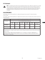 3
3
-
 4
4
-
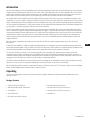 5
5
-
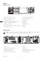 6
6
-
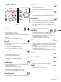 7
7
-
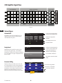 8
8
-
 9
9
-
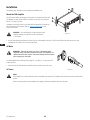 10
10
-
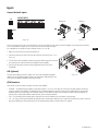 11
11
-
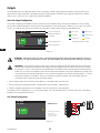 12
12
-
 13
13
-
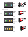 14
14
-
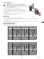 15
15
-
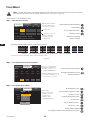 16
16
-
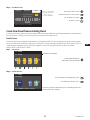 17
17
-
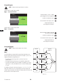 18
18
-
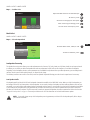 19
19
-
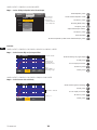 20
20
-
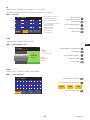 21
21
-
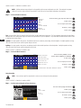 22
22
-
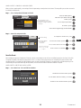 23
23
-
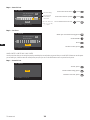 24
24
-
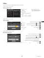 25
25
-
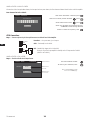 26
26
-
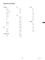 27
27
-
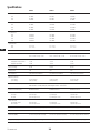 28
28
-
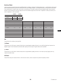 29
29
-
 30
30
-
 31
31
-
 32
32
-
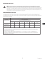 33
33
-
 34
34
-
 35
35
-
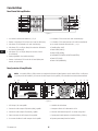 36
36
-
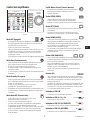 37
37
-
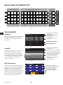 38
38
-
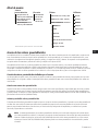 39
39
-
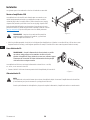 40
40
-
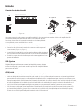 41
41
-
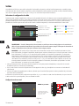 42
42
-
 43
43
-
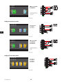 44
44
-
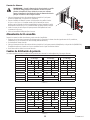 45
45
-
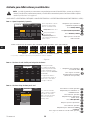 46
46
-
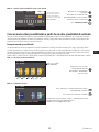 47
47
-
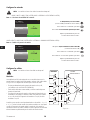 48
48
-
 49
49
-
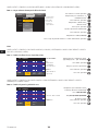 50
50
-
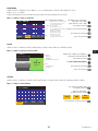 51
51
-
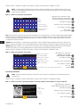 52
52
-
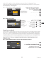 53
53
-
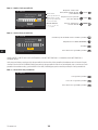 54
54
-
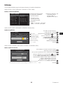 55
55
-
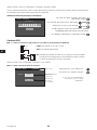 56
56
-
 57
57
-
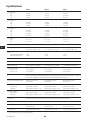 58
58
-
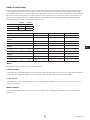 59
59
-
 60
60
-
 61
61
-
 62
62
-
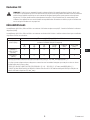 63
63
-
 64
64
-
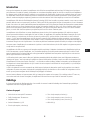 65
65
-
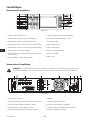 66
66
-
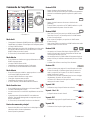 67
67
-
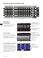 68
68
-
 69
69
-
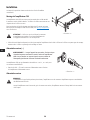 70
70
-
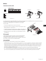 71
71
-
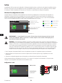 72
72
-
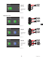 73
73
-
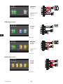 74
74
-
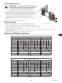 75
75
-
 76
76
-
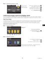 77
77
-
 78
78
-
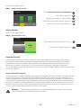 79
79
-
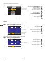 80
80
-
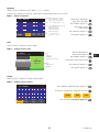 81
81
-
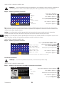 82
82
-
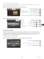 83
83
-
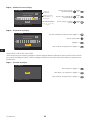 84
84
-
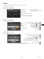 85
85
-
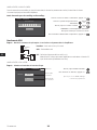 86
86
-
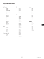 87
87
-
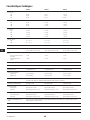 88
88
-
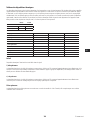 89
89
-
 90
90
-
 91
91
-
 92
92
-
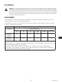 93
93
-
 94
94
-
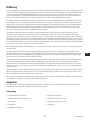 95
95
-
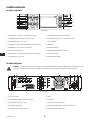 96
96
-
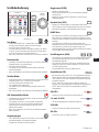 97
97
-
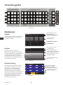 98
98
-
 99
99
-
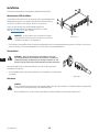 100
100
-
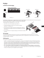 101
101
-
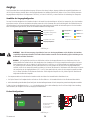 102
102
-
 103
103
-
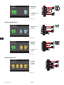 104
104
-
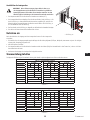 105
105
-
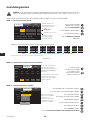 106
106
-
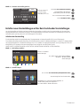 107
107
-
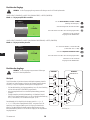 108
108
-
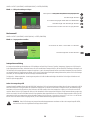 109
109
-
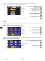 110
110
-
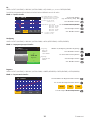 111
111
-
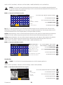 112
112
-
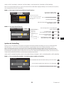 113
113
-
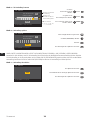 114
114
-
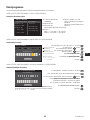 115
115
-
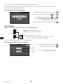 116
116
-
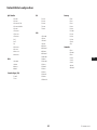 117
117
-
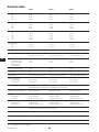 118
118
-
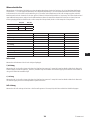 119
119
-
 120
120
-
 121
121
-
 122
122
-
 123
123
-
 124
124
-
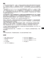 125
125
-
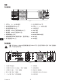 126
126
-
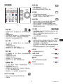 127
127
-
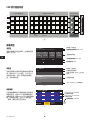 128
128
-
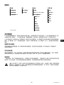 129
129
-
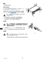 130
130
-
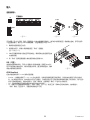 131
131
-
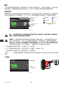 132
132
-
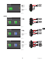 133
133
-
 134
134
-
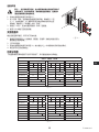 135
135
-
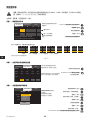 136
136
-
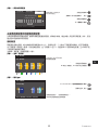 137
137
-
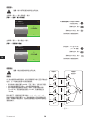 138
138
-
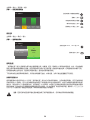 139
139
-
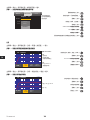 140
140
-
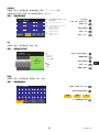 141
141
-
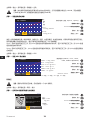 142
142
-
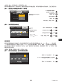 143
143
-
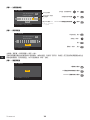 144
144
-
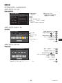 145
145
-
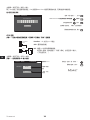 146
146
-
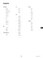 147
147
-
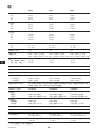 148
148
-
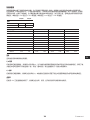 149
149
-
 150
150


QSC Audio CXD4.5 Manual de usuario
- Categoría
- Mezcladores de audio
- Tipo
- Manual de usuario
- Este manual también es adecuado para
en otros idiomas
- français: QSC Audio CXD4.5 Manuel utilisateur
- Deutsch: QSC Audio CXD4.5 Benutzerhandbuch
Otros documentos
-
QSC CXD4.3 Manual de usuario
-
QSC PLD4.2 Guía de inicio rápido
-
QSC CXD4.5Q Manual de usuario
-
QSC DPA4.3Q Manual de usuario
-
Work Pro D4 T Manual de usuario
-
JBL Ti Serie El manual del propietario
-
QSC GXD 8 Manual de usuario
-
QSC GXD4 Guía de inicio rápido
-
QSC CX-Qn 4K4 Manual de usuario
-