HK Audio Lucas 2K18 Manual de usuario
- Categoría
- Altavoces de la barra de sonido
- Tipo
- Manual de usuario
Este manual también es adecuado para

LUCAS 2K15
LUCAS 2K18
MANUAL 1.0
• English • Français• Deutsch • Italiano • Español

Version 2.6 10/2017
Important Safety Instructions!
Read before connecting!
This product has been built by the manufacturer in accordance with
IEC 60065 and left the factory in safe working order. To maintain this
condition and ensure non-risk operation, the user must follow the
advice and warning comments found in the operating instructions. If
this product shall be used in vehicles, ships or aircraft or at altitudes
exceeding 2000 m above sea level, take care of the relevant safety
regulations which may exceed the IEC 60065 requirements.
WARNING: To prevent the risk of fire and shock hazard, do not
expose this appliance to moisture or rain. Do not open case – no user
serviceable parts inside. Refer service to qualified service personnel.
This symbol, wherever it appears, alerts you to the presence
of uninsulated dangerous voltage inside the enclosure – voltage that
may be sufficient to constitute a risk of shock.
This symbol, wherever it appears, alerts you to the presence
of externally accessible hazardous voltage. External wiring connected
to any terminal marked with this symbol must be a “ready made
cable” complying with the manufacturers recommendations, or must
be a wiring installed by instructed persons only.
This symbol, wherever it appears, alerts you to important
operating and maintenance instructions in the accompanying
literature. Read the manual.
This symbol, wherever it appears, tells you: Take care! Hot
surface! To prevent burns you must not touch.
All electrical and electronic products including batteries
should be disposed of separately from the municipal waste stream via
designated collection facilities appointed by the government or the
local authorities.
Read these instructions. Keep these instructions. Follow all
warnings and instructions marked on the product and in this manual.
• Do not use this product near water. Do not place the product near
water, baths, wash basins, kitchen sinks, wet areas, swimming pools
or damp rooms.
• Do not place objects containing liquid on the product – vases,
glasses, bottles etc.
• Clean only with dry cloth.
• Do not remove any covers or sections of the housing.
• The set operating voltage of the product must match the local mains
supply voltage. If you are not sure of the type of power available
consult your dealer or local power company.
• Before connecting the device, please ensure that the mains supply
you are using is equipped with adequate protection against short
circuiting and grounding faults when the device is plugged in.
• To reduce the risk of electrical shock, the grounding of this product
must be maintained. Use only the power supply cord provided with
this product, and maintain the function of the center (grounding)
pin of the mains connection at any time. Make sure the mains outlet
used provides a proper protective ground connection.
• Do not defeat the safety purpose of the polarized or grounding-type
plug. A polarized plug has two blades with one wider than the other.
A grounding type plug has two blades and a third grounding prong.
The wide blade or the third prong are provided for your safety. If the
provided plug does not fit into your outlet, consult an electrician for
replacement of the obolete outlet.
• Protect the power cord from being walked on or pinched particularly
at plugs, convenience receptacles, and the point where they exit
from the device! Power supply cords should always be handled
carefully. Periodically check cords for cuts or sign of stress,
especially at the plug and the point where the cord exits the device.
• Never use a damaged power cord.
• Unplug this product during lightning storms or when unused for long
periods of time.
• This product can be fully disconnected from mains only by pulling
the mains plug at the unit or the wall socket. The product must be
placed in such a way at any time, that disconnecting from mains is
easily possible.
• Fuses: Replace with IEC127 (5x20mm) type and rated fuse for best
performance only! It is prohibited to use “patched fuses” or to short
the fuse-holder. Replacing any kind of fuses must only be carried
out by qualified service personal.
• Refer all servicing to qualified service personnel. Servicing is
required when the unit has been damaged in any way, such as:
- When the power cord or plug is damaged or frayed.
- If liquid has been spilled or objects have fallen into the product.
- If the product has been exposed to rain or moisture.
- If the product does not operate normally when the operating
instructions are followed.
- If the product has been dropped or the cabinet has been damaged.
• Do not connect external speakers to this product with an impedance
lower than the rated impedance given on the product or in this
manual. Use only cables with sufficient cross section according to
the local safety regulations.
• Keep away from direct sunlight.
• Do not install near heat sources such as radiators, heat registers,
stoves or other devices that produce heat.
• This apparatus is for moderate climates areas use, not suitable for
use in tropical climates countries.
• Do not block any ventilation openings. Install in accordance with
manufacturer’s instructions. This product must not be placed in
a built-in installation such as a rack unless proper ventilation is
provided.
• Always allow a cold device to warm up to ambient temperature,
when being moved into a room. Condensation can form inside it and
damage the product, when being used without warming up.
• Do not place naked flame sources, such as lighted candles on the
product.
• The device must be positioned at least 20 cm/8“ away from walls.
• Use only with the cart, stand, tripod, bracket or table specified by
the manufacturer or sold with the product. When a cart is used, use
caution when moving the cart/product combination to avoid injury
from tip-over.
• Use only accessories recommended by the manufacturer, this applies
for all kind of accessories, for example protective covers, transport
bags, stands, wall or ceiling mounting equipment. In case of
attaching any kind of accessories to the product, always follow the
instructions for use, provided by the manufacturer. Never use fixing
points on the product other than specified by the manufacturer.
• This appliance is NOT suitable to be used by any person or persons
(including children) with limited physical, sensorical or mental
ability, or by persons with insufficient experience and/or knowledge
to operate such an appliance. Children under 4 years of age must be
kept away from this appliance at all times.
• Never push objects of any kind into this product through cabinet
slots as they may touch dangerous voltage points or short out parts
that could result in risk of fire or electric shock.
• This product is capable of delivering sound pressure levels in excess
of 90 dB, which may cause permanent hearing damage! Exposure
to extremely high noise levels may cause a permanent hearing loss.
Wear hearing protection if continously exposed to such high levels.
• The manufacturer only guarantees the safety, reliability and
efficiency of this product if:
- Assembly, extension, re-adjustment, modifications or repairs are
carried out by the manufacturer or by persons authorized to do so.
- The electrical installation of the relevant area complies with the
requirements of IEC (ANSI) specifications.
- The unit is used in accordance with the operating instructions.
• This product is optimized for use with music and speech signals.
Using this product with sine wave, square wave or other kind of
measuring signals at higher level may lead to severe damage of the
product.
General Notes on Safety for Loudspeaker
Systems
Mounting systems may only be used for those loudspeaker
systems authorized by the manufacturer and only with the mounting
accessories specified by the manufacturer in the installation
instructions. Read and heed the manufacturer’s installation
instructions. The indicated load-bearing capacity cannot be
guaranteed and the manufacturer will not be liable for damages in the
event of improper installation or the use of unauthorized mounting
accessories.
The system’s load-bearing capacity cannot be guaranteed and
the manufacturer will not be liable for damages in the event that
loudspeakers, mounting accessories, and connecting and attaching
components are modified in any way.
Components affecting safety may only be repaired by the
manufacturer or authorized agents, otherwise the operating permit
will be voided.
Installation may be performed qualified personnel only,
and then only at pick-points with sufficient load-carrying capacity
and in compliance with local building regulations. Use only the
mounting hardware specified by the manufacturer in the installation
instructions (screws, anchors, etc.). Take all the precautions necessary
to ensure bolted connections and other threaded locking devices will
not loosen.
Fixed and portable installations (in this case, speakers
and mounting accessories) must be secured by two independent
safeties to prevent them from falling. Safeties must be able to
catch accessories or parts that are loose or may become loose.
Ensure compliance with the given national regulations when using
connecting, attaching, and rigging devices. Factor potential dynamic
forces (jerk) into the equation when determining the proper size and
load-bearing capacity of safeties.
Be sure to observe speaker stands’ maximum load-bearing
capacity. Note that for reasons of design and construction, most
speaker stands are approved to bear centric loads only; that is, the
speakers’ mass has to be precisely centered and balanced. Ensure
speaker stands are set up stably and securely. Take appropriate added
measures to secure speaker stands, for example when:
- the floor or ground surface does not provide a stable, secure base.
- they are extended to heights that impede stability.
- high wind pressure may be expected.
- there is the risk that they may be knocked over by people.
Special measures may become necessary as precautions against
unsafe audience behavior. Do not set up speaker stands in evacuation
routes and emergency exits. Ensure corridors are wide enough and put
proper barriers and markings in place when setting speaker stands up
in passageways. Mounting and dismounting are especially hazardous
tasks. Use aids suitable for this purpose. Observe the given national
regulations when doing so.
Wear proper protection (in particular, a helmet,
gloves, and safety shoes) and use only suitable means of ascent
(ladders, scaffolds, etc.) during installation. Compliance with this
requirement is the sole responsibility of the company performing the
installation.
WARNING!
After installation, inspect the system comprised
of the mounting fixtures and loudspeakers to ensure it is properly
secured.
The operator of loudspeaker systems (fixed or portable) must
regularly inspect or task a third party to regularly inspect all system
components in accordance with the given country’s regulations and
have possible defects repaired immediately.
We also strongly recommend maintaining a logbook or the like to
document all inspections.
When installing speakers for longer lasting or permanent outdoor
operation, be sure to take into account the stability and load-bearing
capacity of platforms and surfaces; loads and forces exerted by
wind, snow, and ice; as well as thermal influences. Also be sure to
provide sufficient safety margins for the rigging points used for flown
systems. Observe the given national regulations when doing so.
• Ask the manufacturer if your product is allowed for outdoor usage !
Professional loudspeaker systems can produce harmful
volume levels. Even prolonged exposure to seemingly harmless levels
(starting at about 95 dBA SPL) can cause permanent hearing damage!
Therefore we recommend that everyone who is exposed to high
volume levels produced by loudspeaker systems wears professional
hearing protection (earplugs or earmuffs).
Manufacturer: Stamer Musikanlagen GmbH, Magdeburger Str. 8,
66606 St. Wendel, Germany

LUCAS 2K15/2K18 1.0
3
Welcome to the HK Audio family!
Thank you for choosing a brand-name product made by our company. Rest
assured, we engineered and built it with the greatest care so it will serve
you well for many tomorrows to come.
Even if your experience with sound systems runs deep, some things
about this product are sure to be new to you. This is why we ask that you do
not set this manual aside without reading it fi rst. Be sure to keep it in a
safe place for later reference.
Here’s wishing you the best sound at every occasion!
Your HK Audio team
Warranty
Use the convenient online registration option at www.hkaudio.com.
http://warranty.hkaudio.com
The registration is only valid if the device is registered within 30 days of
the date of purchase.
HK AUDIO
Technischer Service
Postfach 1509
66595 St. Wendel, Germany
Fax: +49 6851 905 100
Strong electromagnetic interference or electrostatic discharge
may prevent the product from functioning normally. If this happens, the
product may be returned to normal operation by powering o and on
again. Should this not result in the product functioning normally again,
please move the product away from the source of disturbance and try
again.
1 General Information
Unpacking and Inventorying
When you fi rst unpack your LUCAS 2K15 or LUCAS 2K18, take a quick
inventory to make sure the package comes complete with all the contents.
LUCAS 2K consists of a subwoofer and two satellites. A mains cable is also
included.
The System's Components
LUCAS 2K18LUCAS 2K15
The Subwoofer
The LUCAS 2K15 subwoofer is loaded with a 15" woofer; the LUCAS 2K18
with an 18" woofer. Each houses the system's active circuitry and the Class
D power amplifi ers. The connection and control panel is on the rear.
The Satellites
The two each LUCAS 2K15 and LUCAS 2K18 satellites are equipped with an
8" midrange woofer and a 1" compression driver with a 90° x 55° CD horn.
A Speakon NL2 input is on the rear. The 3° MonoTilt™ pole mount on the
bottom serves to place the satellites on a speaker stand.
Heads up! The system’s components are matched for the best
possible audio performance and may only be operated in the specifi ed
confi guration. The use of satellites other than these will not only degrade
the sound; it may also damage the power amp as well as connected
outboard devices.
LUCAS 2K15 / 2K18
• English • Français• Deutsch • Italiano • Español

LUCAS 2K15/2K18 1.0
4
2 Connectors and Controls
Sub
Sat
Limit
Master
Power
+
6 dB
0 dB
Sub
Power
+6 dB
0 dB
Auto Sleep
On Off
Flat
Bass Boost
Select Bass Boost for
use with L SUB 1500 A
On
O
Input
LR
LR
Thru
Satellites Out
LR
1 1
2 2
11 11
3
4
5
6
7
8
10
9
●
1
Input
Plug a cord equipped with an XLR connector or 1/4”/6.35 mm jack plug into
this electronically balanced XLR/ 1/4”/6.35 mm combo input to send a L/R
stereo line signal from your DJ controller, mixing console, keyboard or the
like to the system.
●
2
Thru
These balanced parallel XLR outputs serve to send the L/R stereo signal
routed into Input (
●
1
) through to other components such as powered
monitors. The Thru jacks also connect the optional HK Audio LINEAR SUB
series model L SUB 1500 or L SUB 1800 A subwoofers. These bass bins
come highly recommended if you wish to boost your system's low-end
performance.
Heads up! The two recommended subwoofer add-ons and the respective
systems are matched to guarantee the best audio performance. We
cannot guarantee that other components will interact properly with your
system.
●
3
Power LED
This LED lights up green when the Power button (
●
10
) is set to On and the
unit is getting mains power.
●
4
Master
The Master knob adjusts the gain and thus the volume for the entire LUCAS
2K system. Turn it all the way down—that is, as far left as it will go—before
switching on the system.
●
5
Sub
The Sub knob adjusts the subwoofer’s volume separately. The satellite and
subwoofer's volume levels are relatively balanced when the knob is set to
the 0 dB—that is, the center-notched 12 o’clock position.
●
6
Limit Sat
This LED tells you the limiter is operating in the satellites' frequency range.
Heads up! If the Sat LED stays red while the system is up and running,
it is being overloaded. Turn down the Master knob! If you are not
feeding a signal into the system and the LED stays red, there has been
malfunction. Contact our Technical Service.
●
7
Limit Sub
This LED tells you the limiter is operating in the subwoofer's low frequency
range.
Heads up! If the Sub LED stays red while the system is up and running,
it is being overloaded. Turn down the Master knob! If you are not
feeding a signal into the system and the LED stays red, there has been
malfunction. Contact our Technical Service.
●
8
Flat/Bass Boost Selector
This DSP-driven EQ optimizes the frequency response for the given
application.
Flat
Bass Boost
Flat: This is the default. When this switch is set to Flat, LUCAS 2K delivers
a factory-tuned, balanced audio image.
Flat
Bass Boost
Bass Boost: If you want LUCAS 2K to pack a more powerful low-end
punch, set the switch to Bass Boost to bring up the subwoofer's low
frequencies.
This switch also serves to adapt the LUCAS 2K's frequency response when
you've added an optional LINEAR SUB series subwoofer to your setup. For
more on this, see section 5, "L SUB 1500 or L SUB 1800 Bass Extensions"
and the confi guration examples shown in the appendix starting on page 32.
●
9
Auto Sleep
LUCAS 2K's Auto Sleep mode is enabled when the button is set to On. If the
system is left to idle for 350 minutes without receiving a signal, the amp
switches to this power-saving mode where it consumes around 0.5 watts.
To wake it up, fi rst press the power button (
●
10
) to switch the system o
for fi ve seconds. Then switch it on again to bring LUCAS 2K back on line. Set
Auto Standby to the O position if you wish to disable this function and
ensure LUCAS 2K remains up and running.
●
10
Power
This is LUCAS 2K's on/o button. The power LED (
●
3
) lights up green when
it is engaged.
●
11
Satellites Out
Plug speaker cords no less than 1.5 mm² thick and equipped with Speakon®
NL2-compatible +1/-1 connectors into these speaker outputs to connect the
LUCAS 2K satellites. If you connect any other device, it and the LUCAS 2K
subwoofer may be irreparably damaged.
Note: Be sure to rotate speaker connectors clockwise until they lock in
place!
Heads up: This type of connector has to be turned clockwise until it
engages. It also has to be disengaged before it can be unplugged. To this
end, pull the bayonet catch towards the cord and turn the connector
counter-clockwise.

LUCAS 2K15/2K18 1.0
5
●
12
Mains
Use the factory-included mains cord to connect this socket to a wall outlet.
Note: LUCAS 2K is equipped with a V-Lock mains socket. If you use a
Volex locking power cord or another optionally available brand with the
same design, you can fi x the power cord in place to prevent accidental
disconnection.
Caution! Make sure the local mains voltage matches the voltage
specifi ed on the LUCAS 2K subwoofer. Connecting it to the wrong mains
voltage may destroy its electronic components.
●
13
Satellite Input
Plug speaker cords no less than 1.5 mm² thick and equipped with Speakon®
NL2-compatible +1/-1 connectors into these speaker outputs to connect the
satellites to the subwoofer's Satellites Out (
●
11
) ports.
Serial No.
2
1
21
Input
LUCAS 2K
SATELLITE
8 Ohms
300 W Program
13
3 Powering Up
• Make sure the mains cord is connected and the Power button (
●
10
) is set
to O .
• Turn the Master (
●
4
) knob all the way down to the far left.
• Connect the two satellites to the subwoofer.
• Switch on all components connected to LUCAS 2K.
• Then push the Power button (
●
10
) to switch on the system.
Heads up: Always switch LUCAS 2K on last—that is, after powering up all
other components—and switch it o fi rst before powering down all other
connected devices.
Left Right
LUCAS 2K
Subwoofer
LUCAS 2K
Satellite
LUCAS 2K
Satellite
Mixer
Input
LR
LR
Thru
Satellites Out
LR
Serial No.
2
1
21
Input
LUCAS 2K
SATELLITE
8 Ohms
300 W Program
Serial No.
2
1
21
Input
LUCAS 2K
SATELLITE
8 Ohms
300 W Program
4 Setting Up
4.1 Placement
The subwoofer needs to be centered between the two satellites for the
system to deliver a balanced stereo image.
4.2 Vertical Alignment
The MonoTilt™ pole mount's 3° angle ensures the satellites remain at their
center of gravity. This slight tilt also serves to better align the speakers to
the audience.
–3°
55°
The MonoTilt™ pole mount's diameter is 36 mm so LUCAS 2K satellites can
be mounted on any standard speaker stand.
Heads up! Always place speaker stands on a stable, sturdy surface and
never exceed the manufacturer's load-bearing specifi cations.
Caution:
• Use only speaker stands that are stable enough to prevent accidental
tipping after satellites are mounted. Ensure the speaker stand is designed
to handle the satellite's weight. Adjustable stands' highest setting must
be limited so as to prevent the combination of speaker stand and satellite
from tipping. This applies when setting the stand on a fl at, horizontal
surface.
• When setting up on an uneven or sloping surface, make sure the speaker
stand's base is secured to prevent accidental tipping, either by attaching
suitable weights to the base or taking other safety measures.
• The use of any other fi xtures or fi ttings can result in instability that may
cause injury.
• English • Français• Deutsch • Italiano • Español

LUCAS 2K15/2K18 1.0
6
4.3 Horizontal Alignment
The satellites’ horizontal directivity is around 90°. Depending on the venue
and room layout, you may want to turn the satellites inwards towards the
audience area.
90°
Dancefloor
Dinner area
LUCAS 2K
Subwoofer
Sat L
Sat R
LUCAS 2K
Subwoofer
Sat L
Dancefloor
Sat R
5 L SUB 1500 or L SUB 1800 Bass
Extensions
You can also extend the LUCAS 2K system with an add-on subwoofer, either
an L SUB 1500 A for LUCAS 2K15 or an L SUB 1800 A for LUCAS 2K18.
• To do this, use two XLR-equipped cords to connect the LUCAS 2K
subwoofer's L/R Thru ports (
●
2
) to the L SUB subwoofer's L/R Inputs.
• Set the LUCAS 2K subwoofer's Flat/Bass Boost selector (
●
8
) to Bass
Boost and the Sub knob (
●
5
) to the 0 dB center-notched position. Set the
connected L SUB unit's Sub-Gain to -6 dB, its X-Over to 100 Hz, and the
Phase switch to 0°.
Heads up: For more on this, see the confi guration examples shown in the
appendix starting on page 32.
Place the two subwoofers next to each other, preferably centered between
the two satellites, for the system to deliver a balanced audio image.
LUCAS 2K L SUB
6 Optional HK Audio Accessories
1. SPEAKER STAND ADD-ON
This package contains two height-adjustable aluminum tripod speaker
stands (112 to 190 cm), two speaker cords, and one bag.
2. LUCAS 2K ROLLER BAG
This package contains a three-piece set of dark grey soft cases, one with an
integrated trolley board for the subwoofer and two for the satellite.
3. 100 mm SWIVEL CASTERS blue
The optional swivel castors are mounted to the rear of the LUCAS 2K
subwoofer using the self-locking screws at the corners.
Heads up! The subwoofer does fi t in the LUCAS 2K Roller Bag with
mounted swivel casters. However, it does fi t in the padded cover for the
L SUB 1500 A or L SUB 1800 A add-on subwoofer.

LUCAS 2K15/2K18 1.0
7
7 Technical Specifi cations
LUCAS 2K System
Total power output (RMS)¹ 670 W Class D
Calculated peak power 2000 W
DSP features FIR Filtering, 24 dB Subsonic Filter, Peak
and RMS Limiters
Housing MDF
Finish Black acrylic enamel
Front grille Metal grille backed with black acoustic foam
Optional Accessories LUCAS 2K ROLLER BAG, SPEAKER STAND
ADD-ON, SPEAKER STAND STRETCH
COVER (tripod cover)
Total weight (2K15) 53,0 kg / 116,9 lbs.
Total weight (2K18) 65,4 kg / 144,2 lbs.
LUCAS 2K15 Subwoofer
Max SPL peak² 129 dB
Frequency response
+/- 5 dB
44 Hz – 130 Hz
Inputs 2x XLR/ 1/4" (6.35 mm) combo inputs
Outputs 2x XLR Thru, 2x Satellites Out (Speakon)
Woofer 1x 15"
Pole mount 1x M20 (K&M)
Grips 2x HK Audio MultiGrip
Dimensions (WxHxD) 48 x 48,5 x 59,5 cm
Weight 30,2 kg / 66,6 lbs.
LUCAS 2K18 Subwoofer
Max SPL peak² 128 dB
Frequency response
+/- 5 dB
39 Hz – 130 Hz
Inputs 2x XLR/ 1/4" (6.35 mm) combo inputs
Outputs 2x XLR Thru, 2x Satellites Out (Speakon)
Woofer 1x 18"
Pole mount 1x M20 (K&M)
Grips 2x HK Audio MultiGrip
Dimensions (WxHxD) 51 x 67 x 72,5 cm
Weight 42,6 kg / 93,9 lbs.
LUCAS 2K Satellite
Max SPL peak² 127 dB
Frequency response
+/- 5 dB
118 Hz – 18 kHz
Midrange speaker 1x 8"
HF driver 1"
Horizontal/vertical direc-
tivity
90° x 55°
Inputs Speaker In (Speakon)
Pole mount HK Audio MonoTilt 3°
Grips 1x routed HK Audio ErgoGrip™
Dimensions (WxHxD) 26,5 x 41,5 x 29,5 cm
Weight 11,4 kg / 25,1 lbs.
General Technical Specifi cations
Peak current 2,6 A / 100-120 V AC • 1,4 A / 220-240 V AC
Inrush current 39 A at 120 V and 230 V
¹ Short-term RMS value measured using a sine burst signal with a 1/4 cycle rate and a resulting crest
factor of 9 dB at a frequency that is representative of the system
² @10% THD, Halfspace
8 Applications
You'll fi nd examples of how to connect components starting on
page 32.
LR
LR
Gain Bass = –6 dB
X-Over Bass = 100 Hz
Phase = 0°
Line
Mic
Gain A
Input A
+6 dB
0 dB
Line
Mic
Gain A
Input A
+6 dB
0 dB
LUCAS 2K
+ Monitoring
+ L SUB
LUCAS 2K
Subwoofer
L SUB
Extension
LUCAS 2K
Satellite
LUCAS 2K
Satellite
Mixer
L5 112 XA L5 112 XA
Input
LR
LR
Thru
Satellites Out
LR
Input
LR
Gain Bass
+6 dB–6 dB
0 dB
180°
0°
120 Hz
100 Hz
Configuration X-Over Bass Phase
LR
Thru
Serial No.
2
1
21
Input
LUCAS 2K
SATELLITE
8 Ohms
300 W Program
Serial No.
2
1
21
Input
LUCAS 2K
SATELLITE
8 Ohms
300 W Program
Sub
+6 dB
0 dB
Flat
Bass Boost
Sub = 0 dB
Input = LineInput = Line
Bass Boost = On
• English • Français• Deutsch • Italiano • Español

Version 2.6 10/2017
Wichtige Sicherheitshinweise!
Bitte vor Anschluss lesen!
Dieses Produkt wurde gemäß IEC 60065 hergestellt und hat das
Werk in einem sicheren, betriebsfähigen Zustand verlassen. Um
diesen Zustand zu erhalten und um einen gefahrlosen Betrieb zu
gewährleisten, ist es notwendig, dass der Benutzer die Empfehlungen
und Warnhinweise befolgt, die in der Betriebsanleitung zu finden
sind. Bei Einsatz dieses Produktes in Fahrzeugen, Schiffen oder
Flugzeugen, oder in Höhen oberhalb 2000 m Meereshöhe müssen
die entsprechenden Sicherheitsstandards zusätzlich zur IEC 60065
beachtet werden.
WARNUNG: Um das Risiko von Feuer oder Stromschlag zu verhüten,
darf dieses Gerät weder Feuchtigkeit noch Regen ausgesetzt werden.
Öffnen Sie das Gehäuse nicht – im Inneren gibt es keine Bauteile,
die vom Benutzer zu warten sind. Die Wartung darf nur von einem
qualifiziertem Kundendienst durchgeführt werden.
Dieses Symbol, wo immer es erscheint, warnt Sie vor
gefährlicher, nicht isolierter Spannung im Gehäuse – Spannung, die
möglicherweise genügt, eine Stromschlaggefahr darzustellen.
Dieses Symbol, wo immer es erscheint, warnt Sie vor von außen
zugänglicher, gefährlicher Spannung. Eine Verbindung zu jeder
Anschlussklemme, die mit diesem Symbol versehen ist, darf nur mit
konfektioniertem Kabel hergestellt werden, dass den Empfehlungen
des Herstellers genügt, oder mit Kabel, das von qualifiziertem
Personal installiert wurde.
Dieses Symbol, wo immer es erscheint, macht Sie auf
wichtige Bedienungs- und Wartungsanweisungen aufmerksam, die in
beiliegenden Unterlagen zu finden sind. Bitte lesen Sie das Handbuch.
Dieses Symbol, wo immer es erscheint, sagt Ihnen: Vorsicht!
Heiße Oberfläche! Um Verbrennungen zu vermeiden, nicht anfassen.
Elektro- und Elektronikgeräte einschließlich Batterien sind
getrennt vom Hausmüll über offizielle Sammelstellen fachgerecht zu
entsorgen.
Bitte lesen Sie diese Anweisungen. Bewahren Sie diese
Anweisungen auf. Befolgen Sie alle Warnhinweise und Anweisungen
auf dem Gerät und in dieser Anleitung.
• Benutzen Sie dieses Gerät nicht in der Nähe von Wasser. Stellen Sie
das Gerät nicht in der Nähe von Wasser, Badewannen, Waschbecken,
Küchenspülen, nassen Stellen, Schwimmbecken oder in feuchten
Räumen auf.
• Stellen Sie keine Gefäße, wie Vasen, Gläser, Flaschen usw., die
Flüssigkeiten enthalten, auf das Gerät.
• Reinigen Sie das Gerät nur mit einem trockenen Tuch.
• Entfernen Sie keine Abdeckungen oder Teile des Gehäuses.
• Die auf dem Gerät angegebene Betriebsspannung muss mit der
örtlichen Spannung der Netzstromversorgung übereinstimmen.
Wenn Sie sich nicht sicher sind, welche Spannung in Ihrem Netz
zur Verfügung steht, konsultieren Sie bitte Ihren Händler oder den
örtlichen Stromversorger.
• Stellen Sie vor Anschluss des Gerätes unbedingt sicher, dass die
Netz versorgungsinstallation über ausreichende Schutz einrichtungen
gegen Kurzschluss und Erdungsfehler angeschlossener Geräte
verfügt.
• Um das Risiko eines Stromschlags zu verringern, muss die
Erdung des Gerätes beibehalten werden. Verwenden Sie nur das
mitgelieferte Stromführungskabel und behalten Sie die Funktion
der seitlichen, geerdeten Schutzkontakte des Netzanschlusses
immer aufrecht. Stellen Sie sicher, dass das Gerät nur an Steckdosen
angeschlossen wird, die über eine ordnungsgemäß funktionierende
Schutzerde verfügen.
• Schützen Sie das Stromführungskabel vor Betreten und Quetschen,
besonders in der Nähe der Stecker, Gerätesteckdosen – und
dort, wo sie am Gerät austreten! Stromführungskabel sollten
immer vorsichtig behandelt werden. Kontrollieren Sie die
Stromführungskabel in regelmäßigen Abständen auf Einschnitte und
Anzeichen von Abnutzung, besonders in der Nähe des Steckers und
an der Verbindung zum Gerät.
• Benutzen Sie niemals ein beschädigtes Stromführungskabel.
• Ziehen Sie bei Gewittern den Stecker des Gerätes und wenn das
Gerät über einen längeren Zeitraum nicht benutzt wird.
• Dieses Gerät wird nur vollständig von Stromnetz getrennt, wenn der
Stecker vom Gerät oder aus der Steckdose gezogen wird. Das Gerät
sollte so aufgestellt werden, dass das Trennen vom Stromnetz leicht
möglich ist.
• Sicherungen: Ersetzen Sie Sicherungen nur mit dem Typ IEC127
(5x20mm) und dem korrekten Nennwert, um die optimale Leistung
zu gewährleisten! Es ist untersagt, kurzgeschlossene Sicherungen zu
verwenden oder den Sicherungshalter zu überbrücken. Sicherungen
dürfen nur von qualifiziertem Personal gewechselt werden.
• Alle Wartungsarbeiten sollten nur von qualifiziertem Personal
ausgeführt werden. Wartung ist notwendig, wenn das Gerät auf
irgendeine Weise beschädigt wurde, wie zum Beispiel:
- Wenn das Stromführungskabel oder der Stecker beschädigt oder
abgenutzt ist.
- Wenn Flüssigkeit oder Gegenstände in das Gerät gelangt sind.
- Wenn das Gerät Regen oder Feuchtigkeit ausgesetzt war.
- Wenn das Gerät nicht ordnungsgemäß funktioniert, obwohl die
Bedienungsanleitung beachtet wurde.
- Wenn das Gerät hingefallen ist oder das Gehäuse beschädigt wurde.
• Beim Anschluss von Lautsprechern an dieses Gerät darf die auf dem
Gerät oder in dieser Anleitung angegebene Mindestimpedanz nicht
unterschritten werden. Die verwendeten Kabel müssen entsprechend
den lokalen Regelungen über einen ausreichenden Querschnitt
verfügen.
• Halten Sie das Gerät vom Sonnenlicht fern.
• Installieren Sie das Gerät nicht in der Nähe von Wärmequellen, wie
zum Beispiel Heizkörper, Heizregister, Öfen oder anderen Geräten,
die Hitze erzeugen.
• Dieses Gerät wurde für die Verwendung in gemäßigten Klimazonen
entwickelt. Nicht geeignet zur Verwendung in tropischen Klimazonen.
• Verstopfen Sie nicht die Lüftungsöffnungen. Installieren Sie das
Gerät entsprechend der Anleitung des Herstellers. Das Gerät darf
nicht eingebaut werden – wie zum Beispiel in einen Gestellrahmen,
es sei denn, dass für angemessene Belüftung gesorgt wird.
• Ein kaltes Gerät sollte immer auf die Umgebungstemperatur
erwärmt werden, wenn es in einen Raum transportiert wird.
Es könnte sich Kondensation im Inneren bilden, die das Gerät
beschädigt, wenn es ohne vorherige Erwärmung benutzt wird.
• Stellen Sie keine offenen Flammen, wie brennende Kerzen, auf das
Gerät.
• Das Gerät sollte mindestens 20 cm von Wänden aufgestellt werden.
• Das Gerät darf nur mit Rollwagen, Ständern, Stativen, Tischen
oder Halterungen benutzt werden, die vom Hersteller spezifiziert
sind oder zusammen mit dem Gerät verkauft wurden. Wenn
ein Rollwagen benutzt wird, seien Sie vorsichtig, wenn Sie die
Rollwagen/Geräte-Kombination transportieren, um Verletzungen
durch Umkippen zu vermeiden.
• Verwenden Sie nur Zubehör, das vom Hersteller empfohlen ist. Das
gilt für alle Arten von Zubehör, wie zum Beispiel Schutzabdeckungen,
Transporttaschen, Ständer sowie Wand- und Deckenhalterungen.
Wenn Sie irgendein Zubehör am Gerät anbringen, befolgen Sie
immer die Anleitungen des Herstellers. Benutzen Sie nur die
Befestigungspunkte des Geräts, die vom Hersteller vorgesehen sind.
• Dieses Gerät ist NICHT geeignet für eine Person oder Personen
(einschließlich Kindern) mit eingeschränkten physischen,
sensorischen und geistigen Fähigkeiten, oder für Personen mit
unzulänglicher Erfahrung und/oder Fachkenntnis, um solch ein Gerät
zu bedienen. Kinder unter 4 Jahren sollten stets von diesem Gerät
fern gehalten werden.
• Es sollten keinerlei Gegenstände durch die Gehäuseschlitze
eingeführt werden, da dadurch gefährliche, spannungsführende
Bauteile berührt oder kurzgeschlossen werden können. Dies könnte
zu einer Feuer- oder Stromschlaggefahr führen.
• Dieses Gerät ist imstande, Schalldruckpegel von mehr als 90 dB zu
produzieren. Dies könnte zu einem dauerhaften Hörschaden führen!
Eine Belastung durch extrem hohe Geräuschpegel kann zu einem
dauerhaften Gehörverlust führen. Bei einer anhaltenden Belastung
durch solch hohe Pegel sollte ein Gehörschutz getragen werden.
• Der Hersteller gewährleistet die Sicherheit, Zuverlässigkeit und
Leistung des Gerätes nur unter folgenden Voraussetzungen:
- Einbau, Erweiterung, Neueinstellung, Modifikationen oder
Reparaturen werden vom Hersteller oder autorisiertem Personal
ausgeführt.
- Die elektrische Installation des betreffenden Bereiches entspricht
den Anforderungen der IEC (ANSI) Maßgaben.
- Das Gerät wird entsprechend der Bedienungsanleitung benutzt.
• Dieses Produkt ist auf die Verwendung mit Musik- und Sprach-
signalen optimiert. Verwendung mit Sinus-, Rechteck- oder anderen
Mess-Signalen bei höherem Pegel kann zu ernsten Beschädigungen
des Geräts führen.
Allgemeine Sicherheitshinweise
für Lautsprechersysteme
Befestigungssysteme dürfen ausschließlich für die vom
Hersteller freigegebenen Lautsprechersysteme und mit dem in der
Montageanleitung genannten Montage-Zubehör verwendet werden.
Die Montagehinweise des Herstellers sind dabei unbedingt zu
beachten. Bei unsachgemäßer Montage bzw. Verwendung von nicht
freigegebenem Montage-Zubehör kann die angegebene Belastung
nicht garantiert und keinerlei Haftung seitens des Herstellers
übernommen werden.
Sollten Änderungen an Lautsprechern, an Montage-Zubehör,
Verbindungs- und Befestigungselementen sowie Anschlagmitteln
vorgenommen werden, kann die Tragfähigkeit des Systems nicht
mehr garantiert werden und seitens des Hersteller keinerlei Haftung
übernommen werden.
Reparaturen an sicherheitsrelevanten Bauteilen dürfen nur vom
Hersteller oder Bevollmächtigten durchgeführt werden, andernfalls
erlischt die Betriebserlaubnis.
Die Installation darf ausschließlich durch Sachkundige und nur
an Montagepunkten mit ausreichender Tragfähigkeit, ggf. unter der
Berücksichtigung von Bauauflagen, erfolgen. Das vom Hersteller in der
Montageanleitung vorgeschriebene Befestigungsmaterial (Schrauben,
Dübel, etc.) muss verwendet werden. Schraubverbindungen müssen
durch geeignete Maßnahmen gegen Lösen gesichert sein.
Ortsfeste oder mobile Installationen (hier Lautsprecher
inkl. Montagezubehör) müssen durch zwei unabhängig voneinander
wirkende Einrichtungen gegen Herabfallen gesichert sein. Lose
Zusatzteile oder sich lösende Teile müssen durch geeignete
Einrichtungen aufgefangen werden können. Bei Verwendung von
Verbindungs- und Befestigungselementen sowie Anschlagmitteln sind
die nationalen Vorschriften zu beachten. Hinsichtlich der Bemessung
der Sicherungsmittel sind mögliche dynamische Belastungen
(Ruckkräfte) mit zu berücksichtigen.
Bei Stativen ist vor allem die maximale Traglast zu beachten.
Außerdem sind die meisten Stative aus konstruktiven Gründen nur
für das Tragen von genau zentrischer Belastung zugelassen. Stative
müssen standsicher aufgestellt werden. Stative sind durch geeignete
Maßnahmen zusätzlich zu sichern, wenn zum Beispiel:
- ihre Aufstandfläche keinen sicheren Stand zulässt,
- ihre Höhen die Standsicherheit einschränken,
- mit zu hohem Winddruck zu rechnen ist,
- damit zu rechnen ist, dass sie durch Personen umgestoßen werden.
Besondere Maßnahmen können auch zur Vorsorge gegen gefährdendes
Verhalten von Zuschauern erforderlich werden. Stative dürfen nicht
in Flucht- und Rettungswegen aufgestellt werden. Bei Aufstellung
in Verkehrswegen ist auf die erforderliche Breite der Wege und
auf ordnungsgemäße Absperrung sowie Kennzeichnung zu achten.
Beim Auf- und Absetzen ist eine besondere Gefährdung gegeben.
Hierzu sind geeignete Hilfsmittel zu verwenden. Es sind hierbei die
nationalen Vorschriften zu beachten.
Während der Montage ist geeignete
Schutzausrüstung (insbesondere Kopfschutz, Handschuhe und
Sicherheitsschuhe) zu tragen und es sind nur geeignete Aufstiegshilfen
(Leitern, Gerüste, etc.) zu verwenden. Die Verantwortung dafür liegt
alleine beim ausführenden Installationsbetrieb.
ACHTUNG! Nach der Montage ist die Aufhängung des System
aus Halterung und Lautsprecher auf sichere Befestigung zu überprüfen.
Der Betreiber von Lautsprechersystemen (ortsfest oder mobil) ist
verpflichtet, alle Systemkomponenten unter Berücksichtigung der
jeweils nationalen Regelungen regelmäßig zu überprüfen bzw. prüfen
zu lassen und mögliche Schäden unverzüglich beseitigen zu lassen.
Weiterhin raten wir dringend zu einer ausführlichen Dokumentation
aller Überprüfungsmaßnahmen in Prüfbüchern o.ä.
Bei längerem oder dauerhaftem Einsatz von Lautsprechern im
Freien sind für Standsicherheit und Tragfähigkeit von Aufbauten und
Flächen insbesondere auch die Windlasten, Schnee- und Eislasten
sowie thermische Einflüsse zu berücksichtigen. Insbesondere
die Lastaufnahmepunkte geflogener Systeme sollten hier mit
ausreichenden Sicherheitsreserven dimensioniert werden. Es sind
hierbei die nationalen Vorschriften zu beachten.
• Fragen Sie den Hersteller, ob Ihr Produkt für den Betrieb im Freien
geeignet ist.
Professionelle Lautsprechersysteme sind in der Lage,
gesundheitsschädliche Schallpegel zu erzeugen. Selbst die Einwirkung
scheinbar harmloser Schallpegel über einen längeren Zeitraum
kann zu bleibenden Schäden am Gehör führen (ab ca. 95dBA
SPL)! Daher raten wir für alle Personen, die durch den Betrieb von
Lautsprechersystemen dem Einfluss hoher Schallpegel ausgesetzt
sind, zum Tragen von professionellem Gehörschutz (Ohrstöpsel oder
Kapselgehörschutz).
Hersteller: Stamer Musikanlagen GmbH, Magdeburger Str. 8,
66606 St. Wendel, Deutschland

LUCAS 2K15/2K18 1.0
9
Willkommen in der HK Audio Familie!
Vielen Dank, dass Sie sich für ein Markenprodukt aus unserem Hause ent-
schieden haben, das mit größter Sorgfalt für Sie entwickelt und gefertigt
wurde.
Auch wenn Sie bereits eingehende Erfahrungen mit Beschallungsan-
lagen gesammelt haben – bei diesem Produkt wird es trotzdem einige
Dinge geben, die neu für Sie sind. Legen Sie deshalb diese Bedienungs-
anleitung nicht ungelesen beiseite und bewahren Sie sie zur späteren
Verwendung auf.
Wir wünschen Ihnen allzeit besten Sound!
Ihr HK Audio Team
Garantie
Nutzen Sie die komfortable Online-Registrierung über www.hkaudio.com.
http://warranty.hkaudio.com
Die Registrierung ist nur gültig, wenn sie innerhalb von 30 Tagen ab
Kaufdatum erfolgte.
HK AUDIO
Technischer Service
Postfach 1509
66595 St. Wendel, Deutschland
Fax: +49 6851 905 100
Hinweis: Die Funktionalität dieses Produkts kann durch starke
elektromagnetische Felder oder elektrostatische Entladungen gestört
werden. In diesem Fall kann durch Ausschalten und erneutes Einschalten
die Funktionalität wieder hergestellt werden. Falls dies nicht hilft, muss
das Gerät von der Störquelle entfernt werden.
1 Allgemeines
Lieferumfang
Bitte überprüfen Sie beim Auspacken Ihres LUCAS 2K15 oder LUCAS 2K18
den Lieferumfang auf Vollständigkeit. LUCAS 2K besteht aus einem
System-Subwoofer und zwei Satelliten – im Lieferumfang ist außerdem
das passende Netzkabel enthalten.
Die Systemkomponenten
LUCAS 2K18LUCAS 2K15
Der Subwoofer
Der System-Subwoofer beherbergt den 15"- (LUCAS 2K15), bzw. 18"-( LUCAS
2K18) Tieftonlautsprecher und die aktive Systemelektronik samt den
Class-D Endstufen. Auf der Rückseite befi nden sich das Anschluss- und
Bedienfeld.
Die Satelliten
Die beiden Satelliten (identisch bei LUCAS 2K15 und LUCAS 2K18) sind mit
einem 8" Tief-Mitteltöner und einem 1" Kompressionstreiber mit 90° x 55°
CD-Horn bestückt. Auf der Rückseite befi ndet sich ein Speakon NL2-Ein-
gang und auf der Unterseite der 3° MonoTilt™-Hochständerfl ansch, um die
Satelliten auf einem Boxenstativ zu montieren.
Hinweis! Die Systemkomponenten sind akustisch optimal aufeinander
abgestimmt und dürfen nur in der angegebenen Konfi guration betrie-
ben werden. Bei Verwendung anderer Satelliten wird nicht nur der Klang
negativ beeinfl usst, sondern die Endstufe – wie auch angeschlossene
Fremdgeräte – können Schaden nehmen.
LUCAS 2K15 / 2K18
• English • Français• Deutsch • Italiano • Español

LUCAS 2K15/2K18 1.0
10
2 Anschlüsse und Bedienelemente
Sub
Sat
Limit
Master
Power
+
6 dB
0 dB
Sub
Power
+6 dB
0 dB
Auto Sleep
On Off
Flat
Bass Boost
Select Bass Boost for
use with L SUB 1500 A
On
O
Input
LR
LR
Thru
Satellites Out
LR
1 1
2 2
11 11
3
4
5
6
7
8
10
9
●
1
Input
Symmetrische Kombi-Eingangsbuchsen (XLR/Klinke) zum Anschluss eines
Stereo-Line-Signals (L/R). Schließen Sie hier das Signalkabel von Ihrem
DJ-Controller, Mischpult, Keyboard o.ä. mittels XLR-Kabel oder 6,35mm-
Klinkenkabel an.
●
2
Thru
Symmetrische, parallele XLR-Ausgänge zur Weiterleitung des am Input
(
●
1
) anliegenden Eingangssignals (L/R). Über Thru kann dieses Stereo-
Signal an weitere Komponenten wie beispielsweise Aktiv-Monitore
weitergeleitet werden. Die Thru-Buchsen dienen auch zum Anschluss der
optional empfohlenen Bass-Erweiterung mit den Subwoofern der HK Audio-
Serie LINEAR SUB: L SUB 1500 bzw. L SUB 1800 A.
Hinweis! Wir garantieren das akustisch korrekte Zusammenspiel der
einzelnen Komponenten nur für die beiden von uns empfohlenen Sub-
Erweiterungen.
●
3
Power-LED
Diese LED leuchtet grün, wenn der Power-Schalter (
●
10
) auf „On“ geschaltet
ist und eine Stromverbindung besteht.
●
4
Master
Über den Master-Regler wird die Eingangsempfi ndlichkeit und somit die
Lautstärke des gesamten LUCAS 2K-Systems angepasst. Drehen Sie den
Master-Regler vor dem Einschalten des Systems ab (Linksanschlag).
●
5
Sub
Über den Sub-Regler kann der Pegel des Subwoofers separat eingestellt
werden. Bei der Einstellung auf 0 dB (Centerclick), hat das System ein
relativ ausgewogenes Lautstärke-Verhältnis zwischen Satelliten und
Subwoofer.
●
6
Limit Sat
Diese LED zeigt das Eingreifen des Limiters im Arbeitsbereich der Satelliten
an.
Achtung! Leuchtet die Sat-LED während des Betriebs dauerhaft rot, wird
das System überlastet. Reduzieren Sie den Master! Sollte kein Signal
anliegen und die LED dauerhaft rot leuchten, liegt ein Fehler vor – kon-
taktieren Sie unseren Technischen Service.
●
7
Limit Sub
Diese LED zeigt das Eingreifen des Limiters im Tieftonbereich beim Sub-
woofer an.
Achtung! Leuchtet die Sub-LED während des Betriebs dauerhaft rot, wird
das System überlastet. Reduzieren Sie den Sub-Regler bzw. den Master!
Sollte kein Signal anliegen und die LED dauerhaft rot leuchten, liegt ein
Fehler vor – kontaktieren Sie unseren Technischen Service.
●
8
Wahlschalter "Flat/Bass Boost"
DSP-gesteuerte Frequenzgangoptimierung an den jeweiligen Anwendungs-
fall.
Flat
Bass Boost
Stellung "Flat": In dieser Schalterstellung hat LUCAS 2K ein werkseitig
eingestelltes, ausgewogenes Klangbild.
Flat
Bass Boost
Stellung "Bass Boost": Die Bass Boost-Funktion erhöht den Tiefbass-An-
teil des Subwoofers und verleiht dem LUCAS 2K bei Bedarf mehr Bassdruck.
Gleichzeitig dient dieser Schalter zur Anpassung des LUCAS 2K bei Verwen-
dung einer optionalen Bass-Erweiterung aus der LINEAR SUB-Serie (siehe
auch Kapitel 5 „Bass-Erweiterung mit L SUB 1500 bzw. L SUB 1800“ und die
Anschlussbeispiele im Anhang ab Seite 32).
●
9
Auto Sleep
LUCAS 2K verfügt über eine Auto Sleep-Funktion, die ein- und ausgeschal-
tet werden kann. Bei Stellung „On“ (Funktion Auto Sleep aktiv) schaltet die
Endstufe – sofern 350 Minuten kein Signal anliegt – in den Ruhezustand
(Verbrauch etwa 0,5 Watt). Um LUCAS 2K wieder in Betriebszustand zu
versetzen, schalten Sie das System über den Power-Schalter (
●
10
) für fünf
Sekunden aus und anschließend wieder ein. Auto Sleep auf „o “ deakti-
viert diese Funktion und LUCAS 2K bleibt dauerhaft in Betrieb.
●
10
Power
Der Ein/Aus-Schalter für den LUCAS 2K. In eingeschaltetem Zustand leuch-
tet die Power-LED (
●
3
) grün.
●
11
Satellites Out
Speaker-Ausgangsbuchsen zum Anschluss der Satelliten des LUCAS 2K
mit NL2-Speakon-kompatiblen Lautsprecherkabeln (+1/-1, Kabelquerschnitt
mind. 1,5 mm²). Verbinden Sie diese Ausgangsbuchsen ausschließlich mit
den LUCAS 2K-Satelliten. Werden andere Geräte angeschlossen, können
diese – wie auch der LUCAS 2K Subwoofer – zerstört werden.
Hinweis: Die Speaker-Stecker müssen durch Drehen im Uhrzeigersinn ein-
rasten. Das Herausziehen ist erst nach Entsicherung der Stecker möglich
– dazu den Bajonettverschluss in Richtung des Kabels ziehen und gegen
den Uhrzeigersinn drehen.

LUCAS 2K15/2K18 1.0
11
●
12
Mains
Verbinden Sie diese Anschlussbuchse mittels des
mitgelieferten Netzkabels mit der Netzsteckdose.
Hinweis: LUCAS 2K ist mit verriegelbaren V-Lock-
Netzeingangsbuchsen ausgestattet. In Kombi-
nation mit einem verriegelbaren Anschlusskabel
("Volex" oder baugleich, optional erhältlich) kann
das Netzkabel arretiert und so gegen versehent-
liches Herausrutschen gesichert werden.
Achtung! Achten Sie darauf, dass die Spannungsangabe auf dem
LUCAS 2K Subwoofer Ihrer lokalen Netzspannung entspricht. Der
Anschluss an eine falsche Netzspannung kann die Elektronik des Gerätes
zerstören.
●
13
Satellite Input
Verbinden Sie über die Speaker-Eingangsbuchsen die Satelliten mit
dem Satellites Out (
●
11
) des System-Subwoofer mittels NL2-Speakon-
kompatiblen Lautsprecherkabeln (+1/-1, Kabelquerschnitt mind. 1,5 mm²).
Serial No.
2
1
21
Input
LUCAS 2K
SATELLITE
8 Ohms
300 W Program
13
3 Inbetriebnahme
• Achten Sie darauf, dass das Netzkabel angeschlossen ist und der Power-
Schalter (
●
10
) auf der Stellung O steht.
• Drehen Sie den Master (
●
4
) ab (Linksanschlag).
• Verbinden Sie die beiden Satelliten mit dem System-Subwoofer.
• Schalten Sie alle an LUCAS 2K angeschlossenen Komponenten ein.
• Schalten Sie nun das System mit dem Power-Schalter (
●
10
) an.
Achtung: LUCAS 2K muss immer zuletzt, d.h. nach allen anderen Kompo-
nenten, eingeschaltet und zuerst, d.h. vor allen angeschlossenen Geräten
ausgeschaltet werden.
Left Right
LUCAS 2K
Subwoofer
LUCAS 2K
Satellite
LUCAS 2K
Satellite
Mixer
Input
LR
LR
Thru
Satellites Out
LR
Serial No.
2
1
21
Input
LUCAS 2K
SATELLITE
8 Ohms
300 W Program
Serial No.
2
1
21
Input
LUCAS 2K
SATELLITE
8 Ohms
300 W Program
4 Aufstellung
4.1 Aufbau des Systems
Um ein möglichst homogenes Stereo-Klangbild zu gewährleisten, sollte der
Subwoofer mittig zwischen den beiden Satelliten platziert werden.
4.2 Vertikale Ausrichtung der Satelliten
Durch den Winkel von 3° sorgt der MonoTilt™-Hochständerfl ansch dafür,
dass die Satelliten stets im Schwerpunkt – und wegen der leichten Neigung
besser auf das Publikum ausgerichtet sind.
–3°
55°
Der MonoTilt™-Hochständerfl ansch hat einen Durchmesser von 36 mm,
die Satelliten von LUCAS 2K können also auf jedem handelsüblichen
Lautsprecherstativ aufgestellt werden.
Hinweis! Achten Sie stets auf sicheren Stand und auf die Herstelleranga-
ben zur maximalen Belastung der Stative.
Vorsicht!
• Es dürfen nur Stative verwendet werden, für die nach Montage der Satel-
liten die Kippsicherheit gewährleistet ist. Das Stativ muss für das Gewicht
des Satelliten ausgelegt sein. Die maximale Auszugshöhe ist derart zu
begrenzen, dass die Kombination aus Stativ und Satellit nicht kippt. Dies
gilt bei Aufstellung auf einer ebenen waagerechten Fläche.
• Des Weiteren ist bei Aufstellung auf einer unebenen oder geneigten
Fläche darauf zu achten, dass die Kippsicherheit gewährleistet wird,
entweder durch Beschwerung des Stativfußes mit geeigneten Gewichten
oder durch anderweitige Sicherungsmaßnahmen.
• Die Verwendung mit anderen Einrichtungen kann zur Instabilität führen,
die Verletzungen verursachen kann.
• English • Français• Deutsch • Italiano • Español
7_Ţ)[
1.4 A rated current
Mains
12

LUCAS 2K15/2K18 1.0
12
4.3 Horizontale Ausrichtung der Satelliten
Die horizontale Abstrahlung der Satelliten beträgt ca. 90°. Drehen Sie je
nach Raumgröße die Satelliten entsprechend ein.
90°
Dancefloor
Dinner area
LUCAS 2K
Subwoofer
Sat L
Sat R
LUCAS 2K
Subwoofer
Sat L
Dancefloor
Sat R
5 Bass-Erweiterung mit L SUB 1500 bzw.
L SUB 1800
Zusätzlich bietet LUCAS 2K die Möglichkeit, das System durch einen weite-
ren Subwoofer (L SUB 1500 A für LUCAS 2K15 und L SUB 1800 A für LUCAS
2K18) zu erweitern.
• Verbinden Sie hierfür die Thru-Buchsen (L/R) (
●
2
) des LUCAS 2K-Sub-
woofers mit den Input-Buchsen (L/R) des L SUB-Subwoofers mit zwei
XLR-Kabeln.
• Stellen Sie den Filter-Wahlschalter (
●
8
) des LUCAS 2K-Subwoofers auf
„Bass Boost“ und drehen Sie den Sub-Regler (
●
5
) auf 0 dB (Centerclick).
Beim verbundenen L SUB stellen Sie den Sub-Gain auf –6 dB, den X-Over
auf 100Hz und den Phase-Schalter auf 0°.
Hinweis: Weitere Informationen erhalten Sie in den Anschlussbeispielen
im Anhang ab Seite 32.
Um ein möglichst homogenes Klangbild zu erhalten, positionieren Sie die
beiden Subwoofer nebeneinander, möglichst mittig zwischen den beiden
Satelliten.
LUCAS 2K L SUB
6 Optionales Zubehör von HK Audio
1. SPEAKER STAND ADD-ON
Inhalt: 2x dreibeiniges u. höhenverstellbares Aluminium-Boxenstativ (112 bis
190 cm), 2x Speaker-Kabel, 1x Tasche.
2. LUCAS 2K ROLLER BAG
Inhalt: dreiteiliger Softcase-Satz (1x Subwoofer mit integriertem Rollbrett
und 2x Satellite), dunkelgrau.
3. LENKROLLEN 100 mm blau
Die optional erhältlichen Lenkrollen können auf der Rückseite des LUCAS
2K-Subwoofers mittels der in den Ecken vorhandenen Sperrzahnschrauben
befestigt werden.
Achtung! Mit montierten Lenkrollen kann der LUCAS 2K Roller Bag nicht
mehr verwendet werden. In diesem Fall eignet sich die passende gepols-
terte Schutzhülle der jeweiligen Bass-Erweiterung L SUB 1500 A bzw.
LSUB 1800 A.

LUCAS 2K15/2K18 1.0
13
7 Technische Daten
LUCAS 2K System
Gesamtleistung (RMS)¹ 670 W Class D
Calculated Peak-Power 2000 W
DSP-Features FIR-Filterung, 24 dB-Subsonic-Filter, Peak-
und RMS-Limiter
Gehäuse MDF
Oberfl äche Acryllack, schwarz
Frontgitter Metallgitter mit schwarzem Akustik-
schaumsto
Optionales Zubehör LUCAS 2K ROLLER BAG, SPEAKER STAND
ADD-ON, SPEAKER STAND STRETCH
COVER (Stativsegel)
Gesamtgewicht (2K15) 53,0 kg / 116,9 lbs.
Gesamtgewicht (2K18) 65,4 kg / 144,2 lbs.
LUCAS 2K15 Subwoofer
Max SPL peak² 129 dB
Frequenzgang +/- 5 dB 44 Hz – 130 Hz
Eingänge 2x Klinke/XLR-Kombibuchse
Ausgänge 2x XLR Thru, 2x Satellites Out (Speakon)
Basslautsprecher 1x 15"
Hochständerfl ansch 1x M20 (K&M)
Gri e 2x HK Audio MultiGrip
Abmessungen (BxHxT) 48 x 48,5 x 59,5 cm
Gewicht 30,2 kg / 66,6 lbs.
LUCAS 2K18 Subwoofer
Max SPL peak² 128 dB
Frequenzgang +/- 5 dB 39 Hz – 130 Hz
Eingänge 2x Klinke/XLR-Kombibuchse
Ausgänge 2x XLR Thru, 2x Satellites Out (Speakon)
Basslautsprecher 1x 18"
Hochständerfl ansch 1x M20 (K&M)
Gri e 2x HK Audio MultiGrip
Abmessungen (BxHxT) 51 x 67 x 72,5 cm
Gewicht 42,6 kg / 93,9 lbs.
LUCAS 2K Satellite
Max SPL peak² 127 dB
Frequenzgang +/- 5 dB 118 Hz – 18 kHz
Mitteltonlautsprecher 1x 8"
Hochtontreiber 1"
Abstrahlung horizontal/
vertikal
90° x 55°
Eingänge Speaker In (Speakon)
Hochständerfl ansch HK Audio MonoTilt 3°
Gri e 1x eingefräster HK Audio ErgoGrip
Abmessungen (BxHxT) 26,5 x 41,5 x 29,5 cm
Gewicht 11,4 kg / 25,1 lbs.
¹ Kurzzeit-RMS-Wert, gemessen unter Verwendung eines Sinus-Burst-Signals mit einer Taktrate
von 1/4 und einem resultierenden Crest-Faktor von 9 dB bei einer für das System repräsentativen
Frequenz
² @10% THD, Halfspace
Allgemeine Technische Daten
Spitzenstrom 2,6 A / 100-120 V AC • 1,4 A / 220-240 V AC
Einschaltstrom 39 A bei 120 V und 230 V
8 Anwendungen
Anschussbeispiele zur Verkabelung fi nden Sie ab Seite 32.
LR
LR
Gain Bass = –6 dB
X-Over Bass = 100 Hz
Phase = 0°
Line
Mic
Gain A
Input A
+6 dB
0 dB
Line
Mic
Gain A
Input A
+6 dB
0 dB
LUCAS 2K
+ Monitoring
+ L SUB
LUCAS 2K
Subwoofer
L SUB
Extension
LUCAS 2K
Satellite
LUCAS 2K
Satellite
Mixer
L5 112 XA L5 112 XA
Input
LR
LR
Thru
Satellites Out
LR
Input
LR
Gain Bass
+6 dB–6 dB
0 dB
180°
0°
120 Hz
100 Hz
Configuration X-Over Bass Phase
LR
Thru
Serial No.
2
1
21
Input
LUCAS 2K
SATELLITE
8 Ohms
300 W Program
Serial No.
2
1
21
Input
LUCAS 2K
SATELLITE
8 Ohms
300 W Program
Sub
+6 dB
0 dB
Flat
Bass Boost
Sub = 0 dB
Input = LineInput = Line
Bass Boost = On
• English • Français• Deutsch • Italiano • Español

Version 2.6 10/2017
Consignes de sécurité importantes! A lire avant
de se connecter!
Ce produit a été construit conformément à la norme IEC 60065 par
le fabricant et a quitté l’usine en bon état de marche. Pour garantir
son intégrité et un fonctionnement sans risque, l’utilisateur se doit
de suivre les conseils et les avertissements préconisés dans cette
notice d’utilisation. En cas d’utilisation de ce produit dans un véhicule
terrestre, un navire ou un avion, ou encore à une altitude supérieure à
2000 mètres, il convient de prendre en considération les normes de
sécurité suivantes, en plus de la norme IEC 60065.
ATTENTION: Afin d’éviter tout risque d‘incendie et d‘électrocution,
n‘exposez pas cet appareil à l’humidité ou à la pluie. N’ouvrez pas
le boîtier; les pièces se trouvant à l’intérieur ne nécessitent pas
d’entretien de la part des utilisateurs. Adressez-vous à un spécialiste
qualifié pour procéder à l‘entretien de l‘appareil.
Ce symbole, quel que soit l’endroit où il apparaît, vous signale
des pièces sous tension non isolées dans le boîtier. Une tension
suffisante pour présenter un risque d’électrocution.
Ce symbole, quel que soit l’endroit où il apparaît, vous signale
des pièces sous tension accessibles depuis l’extérieur du boîtier. Tous les
câbles extérieurs raccordés à un composant marqué de ce symbole
doivent être de type préfabriqués et conformes aux spécifications du
fabricant ou doivent avoir été installés par des spécialistes qualifiés.
Ce symbole, quel que soit l’endroit où il apparaît, vous signale
des instructions importantes relatives à l’utilisation ou l’entretien de
l’appareil à lire dans les documents l’accompagnant. Lisez la notice
d’utilisation.
Ce symbole, quel que soit l’endroit où il apparaît, vous signale
un risque de brûlure dû à une surface chaude. Ne touchez pas cette
surface afin d’éviter de vous brûler.
Tous les appareils électriques et électroniques y compris les
piles doivent être éliminés séparément des déchets ménagers auprès des
points de collecte officiels prévus à cet effet.
Lisez ces instructions. Conservez ces instructions. Prenez en
compte tous les avertissements et toutes les instructions mentionnés
sur le produit ou dans cette notice d’utilisation.
• N’utilisez pas ce produit à proximité de l’eau. Ne le placez pas près de
l’eau, d’une baignoire, d’un bassin, d’un évier, d’une surface humide,
d’une piscine ou d’une pièce humide.
• Ne mettez pas d’objet contenant du liquide sur l’appareil, par exemple,
un vase, un verre ou une bouteille, etc.
• Nettoyez-le exclusivement avec un chiffon sec.
• N’enlevez pas le boîtier, ne serait-ce que partiellement.
• La tension de fonctionnement de l’appareil doit être réglée de manière
à correspondre à la tension d’alimentation de l’endroit où vous vous
trouvez. Si vous n’êtes pas sûr de connaître la tension d’alimentation,
demandez à votre revendeur ou à la compagnie d’électricité locale.
• Avant de brancher l’appareil, assurez-vous systématiquement que
l’installation électrique (alimentation) dispose de systèmes de
protection suffisants contre les courts-circuits et les erreurs de mise à
la terre des appareils raccordés.
• Afin de réduire le risque d’électrocution, vous ne devez jamais
supprimer la mise à la terre de l’appareil. Utilisez uniquement le câble
d’alimentation fourni avec le produit et maintenez la broche centrale
de la prise (mise à la terre) en état de fonctionnement. Ne négligez
pas la sécurité offerte par les prises polarisées ou avec mise à la terre.
Assurez-vous que l’appareil est bien raccordé à une prise disposant
d’une terre de protection et que celle-ci est en ordre de marche.
• Protégez le câble d’alimentation afin d’éviter que quelqu’un marche
dessus ou qu’il soit pincé, notamment près de la prise, de la prise
murale ou à la sortie de l’appareil même! Les câbles d’alimentation
doivent être tout le temps maniés avec précaution. Vérifiez
régulièrement que le câble n’est pas fendu ou qu’il ne présente pas de
signe d’usure, en particulier près de la prise et à la sortie de l’appareil.
• N’utilisez jamais de câble d’alimentation usé.
• Débranchez l’appareil en cas d’orage ou si vous ne l’utilisez pas
pendant une longue période.
• Débranchez l’appareil uniquement en le tenant par la prise au niveau
de la prise murale ou de la rallonge. L’appareil doit être placé de telle
manière à ce qu’il puisse être débranché facilement à tout moment.
• Fusibles: si nécessaire, remplacez-les uniquement par des fusibles de
type IEC127 (5x20mm) afin de garantir une meilleure performance.
Il est interdit d’utiliser des fusibles bricolés ou de raccourcir le porte-
fusible. Seul un personnel qualifié est habilité à remplacer les fusibles.
• Confiez tous les travaux d’entretien à des spécialistes qualifiés.
Il est nécessaire d’effectuer de tels travaux lorsque l’unité a été
endommagée, comme par exemple dans les cas suivants:
- Lorsque le câble d’alimentation est endommagé ou effiloché.
- Si du liquide a pénétré ou un objet est tombé dans le boîtier.
- Si l’appareil a été exposé à la pluie ou à l’humidité.
- Si l’appareil ne fonctionne pas correctement alors que vous avez suivi
toutes les instructions à la lettre.
- Si l’appareil est tombé ou que le boîtier est endommagé.
• En cas de raccordement de haut-parleurs à cet appareil, il faut
veiller à ne pas descendre sous l’impédance minimale indiquée
sur ledit appareil ou dans la présente notice. Les câbles employés
doivent présenter une section suffisante, qui soit conforme aux
réglementations locales en vigueur.
• Ne l’exposez pas directement aux rayons du soleil.
• Ne l’installez pas à proximité d’une source de chaleur, telle qu’un
radiateur, une grille de chauffage, un four ou tout autre appareil
susceptible de produire de la chaleur.
• Cet appareil est conçu pour une utilisation dans des zones climatiques
modérées. Il n'est pas adapté pour une utilisation dans des pays à climat
tropical.
• Ne masquez pas les bouches d’aération. Installez l’appareil
conformément aux instructions du fabricant. Il ne doit pas être placé
dans un emplacement confiné, comme un rack ou une console, sauf si
une ventilation suffisante est garantie.
• Si vous déplacez l’appareil, attendez qu’il soit à température ambiante
avant de le démarrer, sinon de la condensation peut se former à
l’intérieur et endommager l’appareil.
• Ne posez pas de d’objet à flamme ouverte sur l’appareil, comme par
exemple une bougie allumée.
• L’appareil doit être placé à au moins 20cm/8“ pouces du premier mur.
• Utilisez l’appareil uniquement avec un chariot, un support, un trépied,
des fixations ou une table recommandés par le fabricant ou vendus
avec le produit. Si vous utilisez un chariot, maniez-le avec précaution
afin d’éviter tout risque de blessure s’il se renverse.
• Utilisez uniquement les accessoires recommandés par le fabricant.
Cette consigne concerne toute sorte d’accessoires, qu’il s’agisse
de couvercles de protection, de sacs de transport, de supports ou
de dispositifs de fixation au mur ou au plafond. Si vous fixez un
accessoire à l’appareil, suivez toujours les instructions d’utilisation
du fabricant. N’utilisez pas d’autres points de fixation que ceux
préconisés par le fabricant.
• Cet appareil NE convient PAS aux personnes dont les capacités
motrices, sensorielles ou mentales sont déficientes (y compris les
enfants) ou aux personnes ne disposant pas de l’expérience ou des
connaissances nécessaires pour faire fonctionner le présent appareil.
Cet appareil doit dans tous les cas et être tenu constamment hors de
portée des enfants de moins de quatre ans.
• N’insérez jamais d‘objets à travers les grilles du boîtier, car ils
pourraient toucher des pièces sous tension dangereuses ou provoquer
un court-circuit pouvant causer un risque d’incendie ou d’électrocution.
• Cet appareil est capable de délivrer un niveau de pression acoustique
de 90dB, pouvant ainsi causer des troubles irréversibles de l’audition!
L’exposition continue à une nuisance sonore peut provoquer une perte
d’audition permanente. Portez des protections auditives adéquates si
vous vous exposez de manière continue à un tel niveau de pression
acoustique.
• Le fabricant garantit la sécurité, la fiabilité et l’efficacité de
fonctionnement de son produit uniquement si:
- l’assemblage, l’extension, le réajustement, la modification ou la
réparation de l’appareil ont été effectués par le fabricant ou par des
personnes agréées pour ce genre de travaux.
- l’installation électrique concernée est conforme aux normes IEC (ANSI).
- l’unité est utilisée conformément aux instructions d’utilisation.
• Ce produit a été optimisé pour une utilisation avec des signaux
musicaux ou voix. Une utilisation avec des signaux sinusoïdaux,
rectangulaires ou autres signaux de mesure risque de l’endommager
gravement.
Consignes de sécurité générales pour systèmes
de haut-parleurs
Les systèmes de fixation doivent exclusivement être employés
pour les systèmes de haut-parleurs fournis par le fabricant et avec les
accessoires de montage tels qu’évoqués dans la notice de montage. Dans
ce cadre, il convient de respecter scrupuleusement les indications de
montage du fabricant. En cas d’utilisation non conforme d’accessoires ou
d’installation d’accessoires de montage non d’origine, le dommage en
résultant éventuellement ne sera pas couvert par la garantie et la
responsabilité du fabricant ne pourra en aucun cas être engagée.
Si des modifications sont apportées aux haut-parleurs, aux accessoires
de montage, aux raccords et fixations ainsi qu’au matériel d’élingage, la
portabilité du système ne pourra plus être garantie et la responsabilité
du fabricant ne pourra en aucun cas être engagée.
Toute réparation d’éléments de sécurité ne peut être effectuée que
par le fabricant ou son représentant agréé, faute de quoi le permis
d’exploitation s’éteint.
L’installation sera exclusivement réalisée par un spécialiste, et
ce, uniquement dans des zones de montage présentant une capacité de
charge suffisante, un point à vérifier notamment par la prise en compte
des normes de construction appliquées. Le matériel de fixation prescrit
par le constructeur dans la notice de montage (vis, chevilles, etc.) doit
impérativement être employé. Les raccords boulonnés doivent être
assurés contre tout desserrement au moyen de mesures appropriées.
Les installations fixes ou mobiles (ici les haut-parleurs,
accessoires de montage compris) doivent être assurés contre la chute
par deux dispositifs indépendants l’un de l’autre. Les éléments
supplémentaires lâches ou les pièces se desserrant doivent pouvoir être
retenus par des dispositifs adaptés. En cas d’utilisation de raccords,
d’éléments de fixation et de matériel d’élingage, il convient de respecter
les dispositions nationales en la matière. Le calcul du dimensionnement
des dispositifs de sécurité requiert la prise en compte des charges
dynamiques possibles (forces de recul).
En cas d’utilisation de trépieds, il faut surtout prendre en
considération la charge maximale supportée. En outre, de par leur
conception, la plupart des trépieds permettent uniquement de supporter
des charges parfaitement centrées. Les trépieds doivent dès lors être
disposés de façon stable. Il est nécessaire d’assurer les trépieds par des
mesures supplémentaires dans les cas suivants (liste non exhaustive) :
- lorsque leur surface de pose n’offre pas une stabilité suffisante;
- lorsque leur hauteur limite leur stabilité ;
- lorsque la force du vent risque d’être élevée ;
- lorsqu’ils risquent d’être heurtés par des personnes.
Des mesures particulières peuvent également s’avérer nécessaires, à titre
préventif, pour se prémunir contre des comportements dangereux de la
part de spectateurs. Les trépieds ne doivent donc pas être disposés dans
des voies d’évacuation ou des passages réservés aux secours. En cas
d’installation sur des voies de circulation, veiller à respecter la largeur
de circulation requise, à verrouiller le secteur de façon adaptée et à
mettre en place la signalisation idoine. Le montage et le démontage
sont des phases qui présentent des risques particuliers. Il faut dès lors
employer des moyens auxiliaires appropriés. Veiller également, lors de
ces opérations, à respecter la législation nationale en la matière.
Lors du montage, il est indispensable de porter
des équipements de sécurité adaptés (en particulier un casque, des
gants et des chaussures de sécurité) et d’utiliser uniquement des
dispositifs d’aide à l’ascension adaptés (échelles, échafaudages, etc.).
La responsabilité dans ce domaine incombe uniquement à la société de
montage exécutante.
ATTENTION! À l’issue du montage, il y a lieu de contre-vérifier la
fixation ou la suspension du système (haut-parleurs et supports).
L’exploitant des systèmes de haut-parleurs (fixes ou mobiles) est tenu
de vérifier, ou de faire vérifier, tous les composants du système en
fonction des réglementations en vigueur dans le pays concerné, et de
faire éliminer sans délai les éventuels défauts constatés.
En outre, nous recommandons fortement de constituer une
documentation détaillée sur toutes les mesures d’inspection dans les
registres de contrôle ou similaires.
En cas d’utilisation prolongée ou permanente de haut-parleurs en plein
air, tenir compte, pour la stabilité et la capacité portante des structures
et surfaces, de l’influence de paramètres tels le vent, la neige, la glace
et autres facteurs thermiques. Dans ce cas, il convient en particulier de
dimensionner avec des réserves de sécurité suffisantes les points de
support de charge de systèmes suspendus. Veiller également, lors de ces
opérations, à respecter la législation nationale en la matière.
• Adressez-vous au fabricant pour savoir si votre produit convient à un
usage en extérieur.
Les systèmes de haut-parleurs professionnels sont capables
de produire des niveaux sonores dangereux pour la santé. Même
des niveaux sonores a priori inoffensifs peuvent, en cas d’exposition
prolongée, provoquer des pertes auditives irréversibles (à partir
de 95 dBA SPL environ) ! C’est pourquoi nous conseillons à toutes
les personnes soumises à des niveaux sonores élevés en raison de
l’exploitation de systèmes de haut-parleurs, de porter des protections
auditives professionnelles (bouchons d’oreilles ou casques antibruit).
Fabricant : Stamer Musikanlagen GmbH, Magdeburger Str. 8,
66606 St. Wendel, Allemagne

LUCAS 2K15/2K18 1.0
15
Bienvenue dans la famille HK Audio!
Nous vous remercions d’avoir opté pour un produit de notre marque, produit
que nous avons développé et fabriqué pour vous, avec le plus grand soin.
Même si vous avez déjà une longue expérience des installations de
sonorisation, vous constaterez que ce produit a che certaines caractéris-
tiques qui seront nouvelles pour vous. C’est pourquoi nous vous conseillons
de lire la présente notice et de la conserver ensuite pour consultation
ultérieure.
Nous vous souhaitons le meilleur des sons!
L’équipe HK Audio
Garantie
Vous pouvez utiliser notre service d’enregistrement en ligne convivial sur
notre site www.hkaudio.com.
http://warranty.hkaudio.com
L’enregistrement est uniquement valable lorsqu’il est e ectué dans les 30
jours qui suivent la date d’achat.
HK AUDIO
Service technique
Postfach 1509
66595 St. Wendel, Allemagne
Fax: +49 6851 905 100
Conseil: La fonctionnalité de ce produit peut être perturbée par de
puissants champs électromagnétiques ou des décharges électrosta-
tiques. Dans ce cas, il conviendra de couper l’appareil, puis de le rallumer
pour restaurer la fonctionnalité. Si cette mesure ne su t pas, l’appareil
doit être éloigné de la source perturbatrice.
1 Généralités
Contenu de la livraison
Lors du déballage de votre LUCAS 2K15 ou de votre LUCAS 2K18, vérifi ez
l’intégrité de la livraison. Le LUCAS 2K se compose d’un subwoofer système
et de deux satellites. Le câble d’alimentation secteur adapté est également
fourni.
Composants système
LUCAS 2K18LUCAS 2K15
Subwoofer
Le subwoofer système abrite un haut-parleur de basses de 15" (LUCAS
2K15) ou de 18" (LUCAS 2K18), l’électronique système active ainsi que les
étages de sortie de classe D. Au dos fi gurent le panneau de commandes et
les connexions.
Die Satelliten
Les deux satellites (identiques sur les LUCAS 2K15 et LUCAS 2K18) sont
dotés d’un haut-parleur de médiums/graves de 8" et d’un moteur à com-
pression de 1", avec pavillon CD 90° x 55°. Au dos de chacun des deux se
trouve une entrée Speakon NL2 et sur la face inférieure, une embase pour
pied MonoTilt™ 3°, qui permet de monter chacun des satellites sur un pied
pour enceinte.
Conseil: les composants du système sont acoustiquement harmonisés
de façon optimale les uns avec les autres et doivent donc uniquement
être utilisés dans la confi guration proposée. Dès lors, en cas d’utilisation
d’autres satellites, non seulement le son sera infl uencé négativement,
mais l’étage de sortie, ainsi que d’autres appareils tiers éventuellement
raccordés, pourraient subir des dommages.
LUCAS 2K15 / 2K18
• English • Français• Deutsch • Italiano • Español

LUCAS 2K15/2K18 1.0
16
2 Raccords et commandes
Sub
Sat
Limit
Master
Power
+
6 dB
0 dB
Sub
Power
+6 dB
0 dB
Auto Sleep
On Off
Flat
Bass Boost
Select Bass Boost for
use with L SUB 1500 A
On
O
Input
LR
LR
Thru
Satellites Out
LR
1 1
2 2
11 11
3
4
5
6
7
8
10
9
●
1
Input
Douilles d’entrée symétriques combinées (XLR/jack) permettant le raccor-
dement d’un signal Line stéréo (G/D). Raccordez ici le câble de signal de
votre contrôleur DJ, table de mixage, clavier ou autre, via un câble XLR ou un
jack 6,35 mm.
●
2
Thru
Sorties XLR symétriques parallèles, pour la transmission du signal d’entrée
présent en Input (
●
1
) (G/D). Les douilles Thru permettent de transmettre
ce signal stéréo à d’autres composants, comme des moniteurs actifs. Les
douilles Thru servent également à la connexion de l’extension de basses
optionnelle recommandée avec les subwoofers de la série HK Audio LINEAR
SUB: L SUB 1500 ou L SUB 1800 A.
Conseil: nous garantissons l’interaction acoustique correcte des
di érents composants uniquement pour les deux extensions de sub
recommandées par nous.
●
3
LED d’alimentation (Power)
Cette DEL s’allume en vert lorsque l’interrupteur marche/arrêt (
●
10
) (Power)
est sur « On » et qu’une connexion secteur est présente.
●
4
Potentiomètre Master
Le potentiomètre Master permet d’adapter la sensibilité en entrée et ainsi,
le volume de la totalité du système LUCAS 2K. Avant la mise sous tension
du système, coupez le potentiomètre Master (le placer en butée de gauche).
●
5
Potentiomètre Sub
Le potentiomètre Sub permet de régler séparément le niveau du subwoofer.
En position 0 dB (clic central), le système dispose d’un rapport de volume
relativement équilibré entre satellites et subwoofer.
●
6
LED Limit Sat
Cette LED indique l’intervention du limiteur sur la plage de travail des
satellites.
Attention! Si la LED Sat reste rouge durablement avec l’appareil en fon-
ctionnement, c’est que le système subit une surcharge. Réduisez alors le
niveau du potentiomètre Master ! Si aucun signal n’est présent et que la
LED reste allumée en rouge durablement, c’est que le système présente
un dysfonctionnement – contactez alors notre service technique.
●
7
LED Limit Sub
Cette LED indique l’intervention du limiteur sur la plage des extrêmes
basses du subwoofer.
Attention! Si la LED Sub reste rouge durablement avec l’appareil en fonc-
tionnement, c’est que le système subit une surcharge. Réduisez alors le
niveau du potentiomètre Sub ou Master ! Si aucun signal n’est présent et
que la LED reste allumée en rouge durablement, c’est que le système pré-
sente un dysfonctionnement – contactez alors notre service technique.
●
8
Commutateur «Flat/Boost»
Optimisation de la réponse en fréquence gérée par DSP, selon l’application
en cours.
Flat
Bass Boost
Position « Flat » : sur cette position, le LUCAS 2K présente une image
sonore équilibrée, réglée d’usine.
Flat
Bass Boost
Position « Bass Boost » : la fonction Bass Boost augmente la part
d’extrêmes basses du subwoofer et confère au LUCAS 2K, au besoin, une
pression de basses supérieure.
Parallèlement, ce commutateur sert à adapter le LUCAS 2K en cas
d’utilisation d’une extension de basses optionnelle de la série LINEAR SUB
(voir également le chapitre 5 « Extension de basses avec L SUB 1500 ou
LSUB 1800 » et les exemples de connexion en annexe, à partir de la page
32).
●
9
Fonction Auto Sleep
Le système LUCAS 2K intègre une fonction Auto Sleep désactivable. En
position « On“ (fonction Auto Sleep activée), l’étage de sortie bascule en
mode veille – pour autant que le signal ait été absent pendant 350 minutes
(consommation : environ 0,5 watt). Pour ramener le LUCAS 2K en mode de
fonctionnement, coupez l’alimentation au niveau de l’interrupteur marche/
arrêt (Power
●
10
) pendant 5 secondes, puis rallumez. En position « O »,
la fonction Auto Sleep est désactivée ; le LUCAS 2K reste alors activé en
permanence.
●
10
Interrupteur Power
Interrupteur marche/arrêt du LUCAS 2K. Lorsque le système est activé, la
LED Power (
●
3
) s’allume en vert.
●
11
Sorties Satellites Out
Douilles de sorties haut-parleurs permettant le raccordement des satellites
du LUCAS 2K, via des câbles de haut-parleurs compatibles NL2 Speakon
(+1/-1, section de câble :1,5 mm² min.). Ces douilles de sortie seront
uniquement raccordées aux satellites du LUCAS 2K. Si d’autres appareils
devaient être raccordés, ils pourraient être détruits, au même titre d’ailleurs
que le subwoofer du LUCAS 2K.

LUCAS 2K15/2K18 1.0
17
Conseil: les connecteurs des haut-parleurs viennent s’encliqueter par
rotation dans le sens des aiguilles d’une montre. Pour les débrancher, il
convient tout d’abord de retirer la sécurité. Pour ce faire, faire tourner la
fermeture à baïonnette dans le sens du câble et dans le sens contraire
des aiguilles d’une montre.
●
12
Prise Mains
Le câble secteur fourni vient se brancher sur cette prise côté appareil et sur
la prise secteur de l’autre.
Conseil: le LUCAS 2K est doté de prises d’entrée secteur verrouillables de
type V-Lock. Le raccordement verrouillable («Volex» ou de conception
similaire, disponible en option) permet de bloquer le cordon secteur et
d’éviter ainsi tout débranchement accidentel de celui-ci.
Attention! Veillez à ce que la tension indiquée sur le subwoofer du
LUCAS 2K corresponde à la tension secteur disponible. En e et, le
raccordement à une tension secteur incorrecte est susceptible de détruire
l’électronique de l’appareil.
●
13
Satellite Input
Via les douilles d’entrée pour haut-parleurs, raccordez les satellites
Out (
●
11
) du subwoofer système au moyen de câbles de haut-parleurs
compatibles NL2 Speakon (+1/-1, section de câble: 1,5 mm² min.).
Serial No.
2
1
21
Input
LUCAS 2K
SATELLITE
8 Ohms
300 W Program
13
3 Mise en service
• Veillez à ce que le câble secteur soit raccordé et à ce que l’interrupteur
marche/arrêt (Power,
●
10
) soit en position O .
• Coupez l’interrupteur Master (
●
4
) (le ramener en butée de gauche).
• Raccordez les deux satellites au subwoofer système.
• Allumez tous les composants raccordés au système LUCAS 2K.
• Activez à présent le système via l’interrupteur marche/arrêt (Power,
●
10
).
Attention: Le LUCAS 2K doit toujours être mis sous tension en dernier,
c’est-à-dire après tous les autres composants. De la même façon, c’est lui
qui sera coupé en premier, avant tous les appareils raccordés.
Left Right
LUCAS 2K
Subwoofer
LUCAS 2K
Satellite
LUCAS 2K
Satellite
Mixer
Input
LR
LR
Thru
Satellites Out
LR
Serial No.
2
1
21
Input
LUCAS 2K
SATELLITE
8 Ohms
300 W Program
Serial No.
2
1
21
Input
LUCAS 2K
SATELLITE
8 Ohms
300 W Program
4 Installation
4.1 Disposition du système
Afi n de garantir une image sonore stéréo la plus homogène possible, le
subwoofer doit être placé au centre, entre les deux satellites.
4.2 Orientation verticale des satellites
Grâce à l’angle de 3° de l’embase pour pied MonoTilt™ prévue sur les
satellites, ceux-ci reposent toujours sur leur centre de gravité et, en raison
de leur légère inclinaison, sont mieux orientés vers le public.
–3°
55°
L’embase pour pied MonoTilt™ présentant un diamètre de 36 mm, les
satellites du LUCAS 2K peuvent être montés sur tout type de pied de haut-
parleur disponible dans le commerce.
Conseil: veillez toujours à ce que les pieds reposent correctement sur le
sol et à respecter les indications de poids maximal, telles que fournies par
le fabricant.
Attention !
• Seuls peuvent être employés des pieds qui, après montage des satelli-
tes, garantissent la sécurité à l’inclinaison. Le pied doit être conçu pour
supporter le poids du satellite concerné. La hauteur de déploiement totale
doit donc être limitée à celle garantissant que la combinaison du pied et
du satellite ne bascule pas. Cette consigne vaut uniquement pour une
mise en place sur une surface horizontale.
• En cas d’installation sur une surface inégale ou inclinée, il convient de
s’assurer que la sécurité d’inclinaison est garantie, soit grâce à des poids
de lestage appropriés sur la base des pieds, soit par l’adoption d’autres
mesures de sécurité.
• Le recours à d’autres dispositifs peut provoquer une instabilité et dès lors,
causer des blessures.
• English • Français• Deutsch • Italiano • Español

LUCAS 2K15/2K18 1.0
18
4.3 Orientation horizontale des satellites
La plage d’orientation horizontale des satellites est d’environ 90°. Vous
orienterez ceux-ci en fonction de la taille de la salle.
90°
Dancefloor
Dinner area
LUCAS 2K
Subwoofer
Sat L
Sat R
LUCAS 2K
Subwoofer
Sat L
Dancefloor
Sat R
5 Extension de basses pour L SUB 1500
ou L SUB 1800
Le LUCAS 2K o re en outre la possibilité d’étendre le système grâce à un
subwoofer supplémentaire (L SUB 1500 A pour le LUCAS 2K15 et L SUB
1800 A le pour LUCAS 2K18).
• Pour ce faire, raccordez, via deux câbles XLR, les douilles Thru (G/D) (
●
2
)
du subwoofer du LUCAS 2K aux douilles Input (G/D) du subwoofer LSUB.
• Amenez le commutateur de fi ltrage (
●
8
) du subwoofer du LUCAS 2K en
position «Bass Boost», puis le potentiomètre du sub (
●
5
) en position 0dB
(clic central). Si un L SUB est raccordé, placez le Gain du sub sur –6 dB, le
X-Over sur 100Hz et le commutateur de phase sur 0°.
Conseil: pour toute information complémentaire, consultez les exemples
de raccordement en annexe, à partir de la page 32.
Pour obtenir une image sonore la plus homogène possible, positionnez les
deux subwoofers l’un à côté de l’autre, de la façon la plus centrale possible
par rapport aux deux satellites.
LUCAS 2K L SUB
6 Accessoires HK Audio (en option)
1. Kit SPEAKER STAND ADD-ON
Contenu: 2x trépied aluminium pour enceinte, réglable en hauteur (de 112 à
190 cm), 2x câble de haut-parleur, 1x housse.
2. Kit LUCAS 2K ROLLER BAG
Contenu: set de trois housses souples (1x pour le subwoofer, avec plateau à
roulettes intégré et 2x pour satellites), gris foncé.
3. ROULETTES 100 mm, bleues
Les roulettes disponibles en option viennent se fi xer au dos du sub du
LUCAS 2K, via les vis à embase crantée présentes sur les coins.
Attention! Une fois les roulettes montées directement sur le sub, la
housse à roulettes pour LUCAS 2K ne peut plus être employée. Dans
ce cas, il convient d’utiliser la housse de protection rembourrée adap-
tée, propre à chacune des extensions de basses LSUB 1500 A ou LSUB
1800A.

LUCAS 2K15/2K18 1.0
19
7 Caractéristiques techniques
Système LUCAS 2K
Puissance complète
(RMS)¹
670 W, classe D
Puissance de crête
calculée
2000 W
Caractéristiques du DSP Filtrage FIR, fi ltre Subsonic 24 dB, limiteur
de crête et RMS
Caisse MDF
Surface Laque acrylique noire
Grille Grille métallique avec mousse acoustique
noire
Accessoires (en option) LUCAS 2K ROLLER BAG (housse à rou-
lettes), SPEAKER STAND ADD-ON (pieds
supplémentaires pour haut-parleurs),
SPEAKER STAND STRETCH COVER (Cover
en toile tendue pour pied d’enceinte)
Poids total (2K15) 53,0 kg / 116,9 lbs.
Poids total (2K18) 65,4 kg / 144,2 lbs.
Subwoofer du LUCAS 2K15
Crête SPL max.² 129 dB
Réponse en fréquence
+/- 5 dB
44 Hz – 130 Hz
Entrées 2x douille combinée jack/XLR
Sorties 2x XLR Thru, 2x satellites Out (Speakon)
Haut-parleur de basses 1x 15"
Embase pour pied 1x M20 (K&M)
Poignées 2x HK Audio MultiGrip
Dimensions (l x H x P) 48 x 48,5 x 59,5 cm
Poids 30,2 kg / 66,6 lbs.
Subwoofer du LUCAS 2K18
Crête SPL max.² 128 dB
Réponse en fréquence
+/- 5 dB
39 Hz – 130 Hz
Entrées 2x douille combinée jack/XLR
Sorties 2x XLR Thru, 2x satellites Out (Speakon)
Haut-parleur de basses 1x 18"
Embase pour pied 1x M20 (K&M)
Poignées 2x HK Audio MultiGrip
Dimensions (l x H x P) 51 x 67 x 72,5 cm
Poids 42,6 kg / 93,9 lbs.
Satellites du LUCAS 2K
Crête SPL max.² 127 dB
Réponse en fréquence
+/- 5 dB
118 Hz – 18 kHz
Haut-parleur de médiums 1x 8"
Moteur d’aigus 1"
Di usion horizontale/
verticale
90° x 55°
Entrées Speaker In (Speakon)
Embase pour pied HK Audio MonoTilt 3°
Poignées 1x HK Audio ErgoGrip™ fraisée
Dimensions (l x H x P) 26,5 x 41,5 x 29,5 cm
Poids 11,4 kg / 25,1 lbs.
¹ Valeur RMS courte, mesurée par utilisation d’un signal de rafale sinus., avec une cadence de 1/4 et
un facteur de crête résultant de 9 dB, à une fréquence représentative du système.
² À 10% de THD, Halfspace
Caractéristiques techniques générales
Courant de crête 2,6 A / 100-120 V AC • 1,4 A / 220-240 V AC
Courant
d’enclenchement
39 A en 120 V et en 230 V
8 Applications
Vous trouverez des exemples de câblage à partir de la page 32.
LR
LR
Gain Bass = –6 dB
X-Over Bass = 100 Hz
Phase = 0°
Line
Mic
Gain A
Input A
+6 dB
0 dB
Line
Mic
Gain A
Input A
+6 dB
0 dB
LUCAS 2K
+ Monitoring
+ L SUB
LUCAS 2K
Subwoofer
L SUB
Extension
LUCAS 2K
Satellite
LUCAS 2K
Satellite
Mixer
L5 112 XA L5 112 XA
Input
LR
LR
Thru
Satellites Out
LR
Input
LR
Gain Bass
+6 dB–6 dB
0 dB
180°
0°
120 Hz
100 Hz
Configuration X-Over Bass Phase
LR
Thru
Serial No.
2
1
21
Input
LUCAS 2K
SATELLITE
8 Ohms
300 W Program
Serial No.
2
1
21
Input
LUCAS 2K
SATELLITE
8 Ohms
300 W Program
Sub
+6 dB
0 dB
Flat
Bass Boost
Sub = 0 dB
Input = LineInput = Line
Bass Boost = On
• English • Français• Deutsch • Italiano • Español

Version 2.6 10/2017
Istruzioni di sicurezza importanti.
Leggere prima di e ettuare il collegamento!
Il presente prodotto è stato fabbricato dal produttore in conformità
alla norma IEC 60065 ed è uscito dallo stabilimento in perfette
condizioni di funzionamento. Per preservare tali condizioni e
garantirne l’uso sicuro, l’utente deve attenersi alle indicazioni e alle
avvertenze riportate nelle istruzioni per l’uso. Se volete usare questo
prodotto su veicoli, a bordo di navi o di aerei oppure ad altitudini
superiori a 2000 m dovete badare alle rispettive norme di sicurezza
suppletive alla norma IEC 60065.
AVVISO: Per evitare il rischio di incendio o folgorazione, non esporre
l’apparecchio ad umidità o pioggia. Non aprire l’involucro poiché al
suo interno non vi sono parti riparabili dall’utente. Per la riparazione
rivolgersi a personale tecnico qualificato.
Questo simbolo segnala la presenza all’interno dell’involucro
di tensione pericolosa priva di isolamento sufficientemente alta da
costituire un pericolo di folgorazione.
Questo simbolo segnala la presenza di tensione pericolosa
accessibile dall’esterno. Il cablaggio esterno collegato ad un
qualunque morsetto contrassegnato da questo simbolo deve essere un
cavo preconfezionato conforme ai requisiti indicati dal produttore o
un cablaggio installato da personale qualificato.
Questo simbolo segnala importanti istruzioni per l’uso e la
manutenzione nella documentazione allegata. Leggere il manuale.
Questo simbolo ha il seguente significato: Attenzione!
Superficie calda! Non toccare per evitare scottature.
Apparecchiature elettriche o elettroniche di qualsiasi tipo,
batterie incluse, non appartengono nell'immondizia - smaltite questo
tipo di rifiuti presso gli ufficiali centri di raccolta.
Leggere queste istruzioni. Conservare queste istruzioni.
Attenersi a tutti gli avvisi e istruzioni riportati sul prodotto e nel
manuale.
• Non utilizzare il prodotto vicino all’acqua. Non collocare il prodotto
vicino ad acqua, vasche, lavandini, zone umide, piscine o stanze con
presenza di vapore.
• Non collocare sul prodotto oggetti contenenti liquidi, quali vasi,
bicchieri, bottiglie ecc.
• Pulire solo con un panno asciutto.
• Non togliere alcun coperchio o parti dell’involucro.
• La tensione di esercizio prescritta per il prodotto deve corrispondere
alla tensione di alimentazione della rete locale. In caso di dubbi sul
tipo di alimentazione disponibile, rivolgersi al proprio rivenditore o
all’azienda di fornitura elettrica locale.
• Prima di collegare l‘apparecchio, verificate che l‘impianto elettrico
sia munito di adatti dispositivi di protezione contro corto circuito e
errori della messa a terra in apparecchi collegati.
• Per ridurre il rischio di folgorazione, la messa a terra del prodotto
deve essere mantenuta. Utilizzare solo il cavo di alimentazione in
dotazione al prodotto e mantenere sempre in funzione il connettore
centrale (di terra) del collegamento alla rete. Non escludere la
funzione di sicurezza del connettore polarizzato o di messa a terra.
Collegate l‘apparecchio soltanto a prese di corrente con messa in
terra conforme alle norme vigenti.
• Proteggere il cavo di alimentazione affinché non venga calpestato o
pizzicato, in particolare in corrispondenza delle prese e degli innesti
e nel punto di uscita dal dispositivo. Maneggiare sempre con cura
i cavi di alimentazione. Controllare periodicamente la presenza di
tagli o usura sui cavi, soprattutto all’altezza della presa e nel punto
di uscita dal dispositivo.
• Non utilizzare mai il cavo di alimentazione se danneggiato.
• Scollegare il prodotto in caso di temporale o di lunghi periodi di
inutilizzo.
• Il prodotto si scollega completamente dall’alimentazione di rete solo
staccando la spina di alimentazione dall’unità o dalla presa a muro.
Il prodotto va collocato sempre in modo che sia possibile scollegarlo
dall’alimentazione con facilità.
• Fusibili: per garantire prestazioni ottimali, i fusibili utilizzati come
ricambio devono essere di tipo IEC127 (5x20 mm) e dell’amperaggio
nominale richiesto. È vietato utilizzare fusibili riparati o
cortocircuitare il portafusibili. Fate sostituire i fusibili soltanto da
un tecnico qualificato.
• Per tutte le operazioni di riparazione, rivolgersi a personale
qualificato. L’unità va riparata nel caso abbia subito danni, come nei
seguenti casi:
- Il cavo o la presa di alimentazione sono danneggiati o usurati.
- È penetrato del liquido o degli oggetti all’interno del prodotto.
- Il prodotto è stato esposto a pioggia o umidità.
- Il prodotto non funziona correttamente seguendo le istruzioni.
- Il prodotto ha subito una caduta o l’armadio è stato danneggiato.
• Quando collegate altoparlanti badate di non scendere sotto
l’impedenza minima dichiarata sull’apparecchio oppure in questo
manuale. Usate sempre cavi dello spessore adatto e corrispondenti
alle vigenti norme locali.
• Non esporre ai raggi solari diretti.
• Non installare accanto a fonti di calore quali radiatori, bocchette
di diffusione d’aria calda, fornelli o altri dispositivi che generano
calore.
• Apparecchiature elettriche o elettroniche di qualsiasi tipo, batterie
incluse, non appartengono nell'immondizia - smaltite questo tipo di
rifiuti presso gli ufficiali centri di raccolta.
• Non chiudere le aperture di ventilazione. Installare l’unità seguendo
le istruzioni fornite dal produttore. Il prodotto non è adatto
all’installazione ad incasso, ad esempio in un rack, a meno di non
garantire un’adeguata ventilazione.
• Quando viene spostato all’interno di un locale, attendere sempre
che il dispositivo, se freddo, raggiunga la temperatura ambiente.
Qualora venga utilizzato senza che si sia riscaldato, sussiste il
rischio di formazione di condensa al suo interno e di conseguenti
danni.
• Non collocare sul prodotto fiamme libere, come ad esempio candele
accese.
• Il dispositivo va collocato ad almeno 20 cm/8“ di distanza dalle
pareti.
• Utilizzare solo in abbinamento al carrello, supporto, piedistallo,
staffa o tavola specificati dal produttore o venduti insieme al
prodotto. Qualora si utilizzi un carrello, prestare attenzione nello
spostare il carrello/la combinazione di prodotto per evitare lesioni
causate dall’inciampamento.
• Utilizzare solo accessori consigliati dal produttore. Tale prescrizione
si applica a tutti i tipi di accessori, ad esempio coperchi di
protezione, borse per il trasporto, supporti, dispositivi per il
montaggio a parete o a soffitto, ecc. In caso di applicazione
di qualsiasi tipo di accessorio al prodotto, osservare sempre le
istruzioni per l’uso fornite dal produttore. Non utilizzare mai punti
di fissaggio sul prodotto diversi da quelli indicati dal produttore.
• Questo apparecchio NON è adatto all’uso da parte di persone
(compresi i bambini) con capacità fisiche, mentali o sensoriali
limitate o da persone prive della necessaria esperienza e/o
conoscenza. Tenere sempre l’apparecchio al di fuori della portata dei
bambini di età inferiore ai 4 anni.
• Non inserire mai oggetti di alcun tipo all’interno del prodotto
attraverso le fessure dell’armadio, poiché potrebbero toccare punti
con presenza di tensione pericolosa o causare il cortocircuito dei
componenti, con il conseguente rischio di incendio o folgorazione.
• Questo prodotto genera livelli di pressione sonora superiori a 90 dB
in grado di causare danni permanenti all’udito. L’esposizione a livelli
di rumore estremamente elevati può causare la perdita permanente
dell’udito. In caso di esposizione continua, indossare protezioni per
l’udito.
• Il produttore garantisce la sicurezza, l’affidabilità e l’efficienza del
prodotto solo se:
- l’assemblaggio, l’ampliamento, la reimpostazione, le modifiche o le
riparazioni sono eseguiti dal produttore o da personale autorizzato.
- l’impianto elettrico dell’area interessata è conforme ai requisiti
specificati nelle norme IEC (ANSI).
- l’unità è utilizzata secondo le istruzioni per l’uso.
• Questo prodotto è stato concepito per un‘ottima riproduzione di
segnali vocali e musicali. Una riproduzione di segnali sinusoidali,
onde quadre o altri segnali di misurazione a livelli elevati può
gravemente danneggiare l‘apparecchio.
Avvisi di sicurezza per sistemi di altoparlanti
Usate soltanto sistemi di montaggio autorizzati dal produttore
per il rispettivo sistema di altoparlanti. Seguite attentamente le
istruzioni di montaggio ed usate soltanto accessori di montaggio
omologati. È escluso qualsiasi diritto di garanzia in caso di montaggio
improprio o se vengono usati accessori di montaggio non omologati.
Modificazioni agli altoparlanti, agli accessori di montaggio, agli
elementi di connessione e di fissaggio e alle imbracature potrebbero
alterare la stabilità del sistema e faranno decadere ogni forma di
garanzia.
La riparazione di componenti rilevanti dal punto di vista della
sicurezza deve venir eseguita soltanto dal produttore o da un suo
rappresentante autorizzato – altrimenti decadrà ogni forma di
garanzia.
L’istallazione deve venir eseguita soltanto da personale
competente. Usate soltanto punti di montaggio con una sufficiente
capacità portante, considerando eventuali vincoli architettonici. È
assolutamente obbligatorio di usare il materiale di fissaggio (viti,
tasselli ecc.) indicato nelle istruzioni di montaggio del produttore.
Adottate provvedimenti adatti (frenafiletti, dadi autobloccanti) per
prevenire un allentamento dei raccordi filettati.
Assicurate istallazioni stazionarie e/o mobili (in questo caso
gli altoparlanti e gli accessori di montaggio) contro una caduta
dall’alto con due dispositivi indipendenti. Provvedete ad istallare
dispositivi adatti per cogliere ogni elemento allentato prima che
questo possa cadere in terra. Assicuratevi che gli elementi di
montaggio e di fissaggio e le imbracature vengano scelti e montati
nel rispetto delle normative nazionali e locali vigenti. Tenete conto
dei carichi dinamici (forze di trazione-compressione) per calcolare le
dimensioni dei dispositivi di sicurezza.
Se usate stativi, badate che non venga oltrepassato il loro
carico massimo ammissibile. Badate inoltre che, per motivi costruttivi,
gli stativi di solito sono concepiti ed omologati soltanto per portare
un carico centrato. Gli stativi devono essere posizionati in modo sicuro
e stabile. Provvedete ad assicurare (o meglio ancora fissare) gli stativi
se per esempio:
- la loro superficie di appoggio non consenta un posizionamento
stabile,
- la loro altezza limita la stabilità,
- si potrebbero manifestare venti forti,
- potrebbero essere rovesciate da persone.
Prendete provvedimenti contro ogni forma di comportamento
rischioso da parte degli spettatori. È vietato posare stativi che
ingombrano le vie di fuga e l’accesso soccorsi. Se volete posare stativi
in una via di comunicazione, verificate prima che la larghezza della
via lo consenta e badate in ogni caso ad una protezione (transenne,
cordone ecc.) e ad una segnalazione adeguata. Il montaggio e
smontaggio degli altoparlanti significa un rischio elevato. Utilizzate
sempre l’attrezzatura adatta e assicuratevi che le attività vengano
svolte nel rispetto delle normative nazionali in vigore.
Durante il montaggio, indossate sempre
indumenti protettivi appropriati (casco, guanti, calzature di sicurezza)
ed usate soltanto mezzi di salita adatti e sicuri (scala, ponteggio
ecc.). Il rischio è a esclusivo carico della ditta o del tecnico che esegue
i lavori di montaggio.
ATTENZIONE! Verificate dopo il montaggio del sistema di
altoparlanti che il montaggio e cablaggio sia avvenuto in modo
corretto e che tutte le giunzioni siano stabili.
L’operatore di un sistema di altoparlanti (stazionario o mobile)
è obbligato a controllare o a fare controllare regolarmente ogni
componente del sistema nel rispetto delle normative nazionali e locali
in vigore e a fare riparare ogni danno immediatamente.
Vi consigliamo di documentare meticolosamente ogni missione di
controllo in un libretto di controllo.
Per un sicuro montaggio di altoparlanti all’aperto dovete prendere
in considerazione i vari fenomeni che potrebbero limitare la stabilità
e la capacità portante dell’impianto, soprattutto i carichi dovuti al
vento, al peso della neve o del ghiaccio e gli influssi di temperatura.
Badate a dimensionare i punti di sollevamento per un montaggio in
sospensione prendendo in considerazione una sufficiente riserva di
sicurezza. Assicuratevi che tutto avvenga nel rispetto delle normative
nazionali in vigore.
• Se siete insicuri, chiedete al rispettivo producente se il vostro
prodotto sia adatto per un uso all‘aperto.
I sistemi di sonorizzazione professionali sono in grado di
produrre livelli sonori nocivi alla salute. Anche essere sottoposto a
livelli apparentemente inoffensivi (a partire da circa 95 dBA SPL)
per un elevato periodo di tempo può provocare perdite dell’udito.
Quindi consigliamo che ogni persona sottoposta ad alti livelli
sonori provenienti da un sistema di sonorizzazione porti un’adatta
protezione per l’udito (tappi auricolari o paraorecchie).
Produttore: Stamer Musikanlagen GmbH, Magdeburger Str. 8,
66606 St. Wendel, Germania

LUCAS 2K15/2K18 1.0
21
Benvenuti nella famiglia HK AUDIO!
Grazie per aver scelto un prodotto di marca concepito e fabbricato nella
nostra casa secondo i nostri meticolosi criteri di qualità.
Anche se siete un utente esperto di sistemi di sonorizzazione - ques-
to prodotto vi o rirà alcuni aspetti che saranno nuovi per voi. Per questo vi
preghiamo di non ignorare questo manuale e di conservarlo in un luogo
sicuro per averlo sempre a disposizione.
Vi auguriamo il migliore suono in qualsiasi situazione!
Il vostro team HK Audio
Garanzia
Il modo più veloce e confortevole: la registrazione online sul nostro sito
www.hkaudio.com.
http://warranty.hkaudio.com
La registrazione è valida soltanto se avviene su internet ed entro
30 giorni dalla data d’acquisto.
HK AUDIO
Technischer Service (servizio tecnico)
Postfach 1509
66595 St. Wendel, Germania
Fax: +49 6851 905 100
Nota: Forti campi elettromagnetici o scariche elettrostatiche
possono disturbare la funzione del prodotto. In questo caso, basta
spegnere e riaccendere il prodotto per farlo funzionare nuovamente. Se
questo non aiuta a solvere il problema, dovete allontanare il dispositivo
dalla sorgente di disturbo.
1 Informazioni generali
Dotazione
Per favore, verifi cate il contenuto della confezione dopo l'acquisto del
vostro LUCAS 2K15 od LUCAS 2K18. Il sistema LUCAS 2K è composto
da un subwoofer e due satelliti – la confezione contiene anche un cavo
d’alimentazione.
I componenti del sistema
LUCAS 2K18LUCAS 2K15
Il subwoofer
Il subwoofer del sistema è munito di un altoparlante bassi da 15'’ (LUCAS
2K15) rispettivo da 18'’ (LUCAS 2K18) e contiene l'elettronica attiva del
sistema e le fi nali di potenza in classe D. Sul posteriore si trova il panello di
connessione e controllo.
I satelliti
I due satelliti (identici per LUCAS 2K15 e LUCAS 2K18) sono muniti di un al-
toparlante bassi/medi a 8” e di un driver di compressione da 1” con tromba
CD 90° x 55°. Sul posteriore si trova un ingresso Speakon NL2, sull’inferiore
la fl angia MonoTilt™ con un angolo d’inclinazione di 3° per posare i satelliti
su uno stativo.
Nota! I componenti del sistema sono sintonizzati in modo ottimo l’uno
sull’altro e vi consigliamo di utilizzarli soltanto nella confi gurazione
descritta. Usando altro satelliti, il suono non solo risulterà poco soddis-
facente ma rischiate anche di danneggiare sia la fi nale di potenza, sia gli
apparecchi di fabbricazione esterna collegati.
LUCAS 2K15 / 2K18
• English • Français• Deutsch • Italiano • Español

LUCAS 2K15/2K18 1.0
22
2 Caratteristiche dei jack e dei controlli
Sub
Sat
Limit
Master
Power
+
6 dB
0 dB
Sub
Power
+6 dB
0 dB
Auto Sleep
On Off
Flat
Bass Boost
Select Bass Boost for
use with L SUB 1500 A
On
O
Input
LR
LR
Thru
Satellites Out
LR
1 1
2 2
11 11
3
4
5
6
7
8
10
9
●
1
Input
Ingressi bilanciati e combinati (XLR/jack) per collegare un segnale di linea
stereo (L/R). Collegate a queste prese fonti di segnale come DJ-controller,
mixer, tastiera o uno strumento simile usando un cavo XLR oppure jack da
6,35 mm.
●
2
Thru
Uscite bilanciate e parallele (XLR) per un bypass del segnale d’ingresso
(L/R) presente all’Input (
●
1
). Il circuito Thru vi permette di trasmettere il
segnale stereo ad altri componenti, per esempio monitor attivi. Le prese
Thru servono anche per collegare un addizionale subwoofer della serie
HKAudio LINEAR SUB: L SUB 1500 oppure L SUB 1800 A.
Nota! Anche qui vi consigliamo di usare soltanto uno dei due subwoofer
consigliati per ottenere il migliore risultato acustico.
●
3
Power-LED
Questa spia si illumina in verde quando l'interruttore d'alimentazione (
●
10
)
è messo su "On" e quando l'apparecchio è collegato alla rete di corrente.
●
4
Master
Il controllo Master serve a regolare la sensibilità d’ingresso e di conseguen-
za il volume del sistema completo LUCAS 2K. Chiudete il controllo Master
prima di accendere il sistema (girare in senso antiorario).
●
5
Sub
Il controllo Sub permette di regolare indipendentemente il livello del sub-
woofer. Sulla posizione 0 dB(Centerclick), il sistema fornisce una proporzio-
ne assai bilanciata fra il volume dei satelliti e quello del subwoofer.
●
6
Limit Sat
Spia LED che segnala l’azionamento del limiter per i satelliti.
Attenzione! Se la spia Sat rimane rossa durante l'uso, il sistema è sov-
raccaricato. In questo caso dovete ridurre il livello Master! Se la spia si
illumina permanentemente in rosso senza che sia presente un segnale, è
avvenuto un errore – in questo caso, rivolgetevi al nostro servizio tecnico.
●
7
Limit Sub
Spia LED che segnala l’azionamento del limiter per il subwoofer.
Attenzione! Se la spia Sub rimane rossa durante l'uso, il sistema è sovrac-
caricato. In questo caso dovete ridurre il controllo Sub oppure il livello
Master! Se la spia si illumina permanentemente in rosso senza che sia
presente un segnale, è avvenuto un errore – in questo caso, rivolgetevi al
nostro servizio tecnico.
●
8
Selettore "Flat/Bass Boost"
Ottima risposta in frequenza per i vari modi di uso controllata tramite DSP.
Flat
Bass Boost
Posizione "Flat": Impostazione di fabbrica del LUCAS 2K per un suono
armonioso e bilanciato.
Flat
Bass Boost
Posizione "Bass Boost": Se necessario, potete aumentare la quota dei
bassi profondi per rendere i bassi del LUCAS 2K più poderosi.
Questa posizione viene anche usata per collegare un addizionale subwoofer
della serie LINEAR SUB al LUCAS 2K (cfr. capitolo 5. “Collegare un addizio-
nale subwoofer L Sub 1500 oppure L Sub 1800” e gli esempi di collegamento
nell’appendice a partire di pagina 32).
●
9
Auto Sleep
Selettore per attivare o disattivare la funzione automatica di risparmio
energetico del LUCAS 2K. Sulla posizione "On” (funzione Auto Sleep attiva),
lo standby della fi nale di potenza verrà attivato dopo 350 minuti senza
segnale d'ingresso (consumo: 0,5 Watt circa). Per riattivare il LUCAS 2K,
basta premere l'interruttore Power (
●
10
) e aspettare cinque secondi prima
di premerlo di nuovo. Sulla posizione "O " invece, la funzione automatica di
risparmio energetico viene disattivata e il LUCAS 2K rimane acceso.
●
10
Power
Interruttore d’alimentazione del LUCAS 2K. Quando il subwoofer è attivato,
la spia Power (
●
3
) si illumina in verde.
●
11
Satellites Out
Uscita altoparlanti per collegare i satelliti del LUCAS 2K usando cavi
compatibili con NL2-Speakon (+1/-1, diametro del cavo almeno 1,5 mm²).
Collegate queste uscite soltanto ai satelliti del LUCAS 2K. Non collegare altri
dispositivi per evitare che questi, o il subwoofer del LUCAS 2K, si possano
danneggiare irreparabilmente!
Nota: Badate che le prese Speakon incastrano girandole in senso orario.
Per disconnettere i cavi, dovete togliere la sicura tirando la chiusura a
baionetta verso voi e girandola in senso orario.

LUCAS 2K15/2K18 1.0
23
●
12
Mains
Collegate questa presa alle rete di corrente usando il cavo d'alimentazione
in dotazione.
Nota: Il LUCAS 2K è munito di prese d'alimentazione ad alta sicurezza
V-Lock. In combinazione con un cavo d'alimentazione pressa e rilascia
("Volex" o simile, in vendita opzionale) evitate una disconnessione invo-
lontaria del cavo d'alimentazione.
Attenzione! Assicuratevi che la tensione della rete alla quale vi
volete collegare corrisponda al valore indicato sul LUCAS 2K. Collegando
l’apparecchio ad una tensione non adatta rischiate di distruggere
l’elettronica.
●
13
Satellite Input
Collegate gli ingressi Speaker dei satelliti al Satellites Out (
●
11
) del
subwoofer del sistema usando cavi da altoparlanti compatibili con NL2-
Speakon (+1/-1, diametro del cavo almeno 1,5 mm²).
Serial No.
2
1
21
Input
LUCAS 2K
SATELLITE
8 Ohms
300 W Program
13
3 Messa in funzione
• Badate che il cavo d’alimentazione sia collegato e che l’interruttore Power
(
●
10
) si trovi in posizione O .
• Chiudete il Master (
●
4
) (girandolo in senso antiorario).
• Collegate i due satelliti al subwoofer del sistema.
• Attivate tutti i componenti collegati al LUCAS 2K.
• Attivate il sistema usando l’interruttore Power (
●
10
).
Attenzione: Badate di attivare il LUCAS 2K sempre come ultimo, vale a
dire dopo aver attivato tutti i componenti di periferia, e di disattivarlo
sempre prima di disattivare questi.
Left Right
LUCAS 2K
Subwoofer
LUCAS 2K
Satellite
LUCAS 2K
Satellite
Mixer
Input
LR
LR
Thru
Satellites Out
LR
Serial No.
2
1
21
Input
LUCAS 2K
SATELLITE
8 Ohms
300 W Program
Serial No.
2
1
21
Input
LUCAS 2K
SATELLITE
8 Ohms
300 W Program
4 Installazione
4.1 Posizionare il sistema
Per ottenere un omogeneo suono stereo, vi consigliamo di posizionare il
subwoofer nel centro dei due satelliti.
4.2 Orientare i satelliti verticalmente
Grazie all’angolo di 3° della fl angia MonoTilt™, il centro di gravità dei satelliti
si trova in linea con lo stativo e il suono viene orientato in modo migliore
verso gli ascoltatori.
–3°
55°
La fl angia MonoTilt™ ha un diametro di 36 mm, permettendovi di montare i
satelliti del sistema LUCAS 2K su quasi qualsiasi stativo per altoparlanti.
Nota! Badate sempre che gli stativi siano posti in modo stabile e che
questi siano adatti a portare il peso (controllare il carico massimo nelle
specifi cazioni del produttore).
Attenzione!
• Usate soltanto stativi solidi che garantiscono la stabilità della colonna
con satelliti montati. Badate che lo stativo sia adatto a portare il peso
del satellite. Attenzione a non troppo estrarre lo stativo per non superare
l’altezza dove la colonna formata da stativo e satellite diventi instabile!
Questo vale per un installazione su una superfi cie pianeggiante e
orizzontale.
• Su una superfi cie a dislivello o inclinata, dovete provvedere a garantire
la stabilità della colonna, per esempio posando un peso adatto sul piede
dello stativo o fi ssandolo con una cinghia, ecc.
• Montando i satelliti su stativi non adatti o usando soluzione improvvisate,
rischiate che l’impianto diventi instabile e danneggi delle persone.
• English • Français• Deutsch • Italiano • Español

LUCAS 2K15/2K18 1.0
24
4.3 Orientare i satelliti orizzontalmente
La dispersione orizzontale dei satelliti ammonta a 90° circa. Girate i satelliti
tenendo in considerazione le dimensioni della località.
90°
Dancefloor
Dinner area
LUCAS 2K
Subwoofer
Sat L
Sat R
LUCAS 2K
Subwoofer
Sat L
Dancefloor
Sat R
5 Collegare un addizionale subwoofer
LSUB 1500 oppure L SUB 1800
LUCAS 2K vi permette di allargare il sistema collegando un addizionale sub-
woofer (L SUB 1500 A per LUCAS 2K15 e L Sub 1800 A per LUCAS 2K18).
• Collegate le prese Thru (L/R) (
●
2
) del subwoofer del LUCAS 2K alle prese
Input (L/R) del subwoofer L SUB usando due cavi XLR.
• Mettete il selettore fi ltro (
●
8
) del subwoofer del LUCAS 2K su „Bass
Boost“ e girate il controllo Sub (
●
5
) su 0 dB (Centerclick). Sul L SUB
collegato, mettete il Sub-Gain su -6 DB, il X-Over su 100 Hz e il selettore di
fase su 0°.
Nota: Troverete ulteriori informazioni negli esempi di collegamento
nell’appendice a partire di pagina 32.
Per ottenere un suono omogeneo, posizionate i due subwoofer uno a lato
dell’altro e in posizione centrale fra i dei due satelliti.
LUCAS 2K L SUB
6 Accessori opzionali HK Audio
1. SPEAKER STAND ADD-ON
Contenuto: 2 stativi per altoparlanti a treppiedi in alluminio, regolabili in
altezza (112 a 190 cm), 2 cavi speaker, 1 sacca.
2. LUCAS 2K ROLLER BAG
Contenuto: Set di tre soft-cases (1 per il subwoofer con tavola a rotelle
integrata, 2 per i satelliti) in grigio scuro.
3. RUOTE ORIENTABILI 100 mm in blu
Le ruote orientabili in vendita opzionale possono essere fi ssati sul poste-
riore del subwoofer del LUCAS 2K usando le viti zigrinate sottotesta negli
angoli.
Attenzione! Quando avete montato le ruote orientabili, non potete più
usare il roller bag per il LUCAS 2K. In questo caso vi consigliamo di pro-
curarvi la custodia imbottita per un L SUB 1500 A oppure L Sub 1800 A.

LUCAS 2K15/2K18 1.0
25
7 Caratteristiche tecniche
Sistema LUCAS 2K
Potenza totale (RMS)¹ 670 W Class D
Calculated Peak-Power 2000 W
DSP-Features Filtro FIR, fi ltro subsonic 24 dB, limiter peak
e RMS
Custodia MDF (pannello di fi bra a media densità)
Superfi cie Smalto acrilico, nero
Griglia frontale Griglia in metallo con plastico espanso
speciale
Accessori opzionali LUCAS 2K ROLLER BAG, SPEAKER STAND
ADD-ON, SPEAKER STAND STRETCH
COVER (Fodera copristativo)
Peso totale (2K15) 53,0 kg / 116,9 lbs.
Peso totale (2K18) 65,4 kg / 144,2 lbs.
LUCAS 2K15 Subwoofer
SPL Peak massimo² 129 dB
Risposta in frequenza
+/- 5 dB
44 Hz – 130 Hz
Ingressi 2x presa combinata jack/XLR
Uscite 2x XLR Thru, 2x Satellites Out (Speakon)
Altoparlante bassi 1x 15"
Flangia di supporto 1x M20 (K&M)
Manici 2x HK Audio MultiGrip
Dimensioni (L x A x P) 48 x 48,5 x 59,5 cm
Peso 30,2 kg / 66,6 lbs.
LUCAS 2K18 Subwoofer
SPL Peak massimo² 128 dB
Risposta in frequenza
+/- 5 dB
39 Hz – 130 Hz
Ingressi 2x presa combinata jack/XLR
Uscite 2x XLR Thru, 2x Satellites Out (Speakon)
Altoparlante bassi 1x 18"
Flangia di supporto 1x M20 (K&M)
Manici 2x HK Audio MultiGrip
Dimensioni (L x A x P) 51 x 67 x 72,5 cm
Peso 42,6 kg / 93,9 lbs.
LUCAS 2K Satellite
SPL Peak massimo² 127 dB
Risposta in frequenza
+/- 5 dB
118 Hz – 18 kHz
Altoparlante medi 1x 8"
Driver acuti 1"
Dispersione orizzontale/
verticale
90° x 55°
Ingressi Speaker In (Speakon)
Flangia di supporto HK Audio MonoTilt 3°
Manici 1x maniglia incassata HK Audio ErgoGrip™
Dimensioni (L x A x P) 26,5 x 41,5 x 29,5 cm
Peso 11,4 kg / 25,1 lbs.
¹ Valore RMS di breve durata, misurato usando un segnale sinus-burst con una cadenza di 1/4 e un
fattore crest risultante di 9 DB con una frequenza caratteristica per il sistema.
² @10% THD, Halfspace
Caratteristiche tecniche generali
Assorbimento di
corrente massimo
2,6 A / 100-120 V AC • 1,4 A / 220-240 V AC
Corrente di transitorio 39 A con 120 V e 230 V
8 Applicazioni
Alcuni esempi di cablaggio sono illustrati a partire di pagina 32.
LR
LR
Gain Bass = –6 dB
X-Over Bass = 100 Hz
Phase = 0°
Line
Mic
Gain A
Input A
+6 dB
0 dB
Line
Mic
Gain A
Input A
+6 dB
0 dB
LUCAS 2K
+ Monitoring
+ L SUB
LUCAS 2K
Subwoofer
L SUB
Extension
LUCAS 2K
Satellite
LUCAS 2K
Satellite
Mixer
L5 112 XA L5 112 XA
Input
LR
LR
Thru
Satellites Out
LR
Input
LR
Gain Bass
+6 dB–6 dB
0 dB
180°
0°
120 Hz
100 Hz
Configuration X-Over Bass Phase
LR
Thru
Serial No.
2
1
21
Input
LUCAS 2K
SATELLITE
8 Ohms
300 W Program
Serial No.
2
1
21
Input
LUCAS 2K
SATELLITE
8 Ohms
300 W Program
Sub
+6 dB
0 dB
Flat
Bass Boost
Sub = 0 dB
Input = LineInput = Line
Bass Boost = On
• English • Français• Deutsch • Italiano • Español

Version 2.6 10/2017
Importantes instrucciones de seguridad.
¡Leer antes de encender!
Este producto ha sido elaborado por el fabricante de conformidad
con IEC60065 y ha salido de fábrica en perfecto estado. Para que
se mantenga en perfectas condiciones y asegurar que no exista
riesgo alguno, el usuario deberá observar los avisos y advertencias
que se encuentran en el manual de instrucciones. En caso de utilizar
este producto en vehículos, embarcaciones o aviones, así como a
altitudes superiores a los 2.000 m sobre el nivel del mar, además de
la norma IEC 60065 también se deberán cumplir las demás normas de
seguridad aplicables
ADVERTENCIA: Para prevenir el riesgo de incendio y el peligro de
electrocución, evite la exposición del equipo a humedad o lluvia. No
abra la cubierta: en el interior no hay elementos que deba manipular
el usuario. El mantenimiento deberá quedar a cargo de personal
cualificado.
La presencia de este símbolo advierte de la existencia de
tensión peligrosa sin aislar en el interior que podría ser suficiente
para provocar una electrocución.
La presencia de este símbolo advierte de la existencia de
tensión peligrosa accesible desde el exterior. Todo cableado externo
conectado con algún terminal marcado con este símbolo deberá ser un
cableado preelaborado que satisfaga las recomendaciones del
fabricante o deberá ser instalado por personal cualificado.
La presencia de este símbolo advierte de importantes
instrucciones de uso y mantenimiento en la bibliografía adjunta. Lea
el manual.
La presencia de este símbolo indica: ¡Precaución! ¡Superficie
caliente! No tocar para evitar quemaduras.
Todos los aparatos eléctricos y electrónicos inclusive las
baterías, se han de evacuar por separado de la basura doméstica, a
través de centros de recogida y reciclaje oficiales.
Lea las presentes instrucciones. Conserve las presentes
instrucciones. Observe todas las advertencias e indicaciones señaladas
en el producto y en las instrucciones.
• No utilice el producto cerca del agua. No coloque el producto cerca
de agua, baños, bañeras, fregaderos, zonas húmedas, piscinas o
saunas.
• No coloque objetos que contengan líquidos sobre el producto, como
jarrones, vasos, botellas, etcétera.
• Limpie exclusivamente con paños secos.
• No retire ninguna cubierta ni elementos del armazón.
• La tensión operativa del producto deberá ajustarse a la tensión del
suministro eléctrico local. Si no está seguro del tipo de electricidad
disponible, consulte con su distribuidor o con la compañía eléctrica
local.
• Antes de conectar el aparato debe asegurarse de que la instalación
de alimentación de red tenga equipos de protección suficientes
contra cortocircuito y fallo de puesta a tierra de los dispositivos
conectados.
• Para reducir el riesgo de electrocución, deberá mantenerse la puesta
a tierra del producto. Utilice solamente el cable de alimentación
suministrado con el producto y mantenga siempre activo de la
patilla central (puesta a tierra) del cuadro de conexiones. No
desactive la función de seguridad del enchufe polarizado o con
puesta a tierra. El aparato solamente debe conectarse a enchufes
que tengan una puesta a tierra de protección que funcione
reglamentariamente.
• Proteja el cable de alimentación de pisadas o pinzamientos,
especialmente junto a enchufes, soportes de dispositivos y el punto
de salida desde el equipo. Los cables de alimentación deberán
manipularse siempre con precaución. Compruebe periódicamente
que los cables no tengan cortes ni signos de desgaste,
especialmente en el enchufe y en el punto de salida desde el equipo.
• No utilice nunca un cable dañado.
• Desenchufe el producto durante las tormentas con aparato eléctrico
o cuando vaya a estar en desuso durante periodos prolongados.
• El producto solamente se puede desconectar por completo de la red
extrayendo el enchufe de red de la unidad o de la toma de la pared.
El producto deberá colocarse en todo momento de tal modo que su
desconexión de la red sea sencilla.
• Fusibles: Reemplace solamente con fusibles de tipo (5x20 mm) y
amperaje según IEC 127. Está prohibido usar „fusibles parcheados“
o cortocircuitar los portafusibles. La sustitución de los fusibles debe
ser realizada únicamente por personal cualificado.
• El mantenimiento deberá quedar a cargo de personal cualificado.
Será necesaria una revisión si la unidad resulta dañada de cualquier
forma, por ejemplo:
- si el cable de alimentación o el enchufe están dañados o
deshilachados;
- si se han derramado líquidos sobre el producto o han caído objetos
en él;
- si el producto se ha visto expuesto a lluvia o humedad;
- si el producto no funciona con normalidad pese a seguirse las
instrucciones de uso;
- si el producto ha sido salpicado o el cajetín ha sido dañado.
• Cuando se conecten altavoces a este aparato no se podrá sobrepasar
el límite de impedancia mínima especificado en el aparato o en las
presentes instrucciones. La sección de los cables empleados debe
ser suficiente en conformidad con la reglamentación local.
• Proteja de la luz solar directa.
• No instale cerca de fuentes de calor como radiadores, difusores de
calor, estufas u otros dispositivos que produzcan calor.
• Este aparato ha sido desarrollado para su uso en zonas climáticas
moderadas – y no para su uso en zonas climáticas tropicales.
• No bloquee ninguna abertura de ventilación. Instale de conformidad
con las instrucciones del fabricante. No deberá situarse el producto
en una instalación integrada, como una rejilla, a no ser que exista la
ventilación necesaria.
• Permita siempre que un dispositivo frío se caliente a temperatura
ambiente cuando se traslade a alguna sala. Pueden formarse
condensaciones en el interior del producto y dañarlo cuando se usa
sin precalentamiento.
• No sitúe fuentes de llama abierta, como velas encendidas, sobre el
producto.
• El dispositivo deberá situarse al menos a 20cm/8“ de distancia de
las paredes.
• Utilice solamente con el carro, soporte, trípode, abrazadera o
tablero especificado por el fabricante o vendido junto con el
producto. Cuando se use un carro, deberá tenerse precaución al
mover la combinación de carro/producto para evitar daños por
vuelcos.
• Utilice solamente accesorios recomendados por el fabricante;
esto será de aplicación para todo tipo de accesorios, por ejemplo,
cubiertas protectoras, bolsas de transporte, pies, soportes murales
o de techo. En caso de instalación de cualquier tipo de accesorio
en el producto, siga siempre las instrucciones de uso suministradas
por el fabricante. Nunca utilice puntos de fijación distintos de los
especificados por el fabricante.
• El dispositivo NO es apropiado para su uso por parte de cualquier
persona o personas (niños incluidos) con las capacidades
físicas, sensoriales o mentales limitadas o sin la experiencia o el
conocimiento suficientes con productos de este tipo. El dispositivo
deberá mantenerse siempre fuera del alcance de los niños menores
de 4 años.
• Nunca introduzca objetos de ninguna clase en el producto a través
de las ranuras del cajetín, ya que podrían tocar puntos de tensión
peligrosa, ni cortocircuite elementos que pudieran causar riesgo de
incendio o electrocución.
• El producto puede emitir niveles de presión sonora por encima
de 90dB, lo que puede causar daños auditivos permanentes. La
exposición a niveles sonoros extremadamente altos puede causar
pérdidas auditivas permanentes. Lleve protección auditiva si va a
estar expuesto de forma continua a dicho tipo de elevados niveles.
• El fabricante solamente garantiza la seguridad, la fiabilidad y la
eficiencia del producto si:
- el montaje, la extensión, el reajuste, las modificaciones o las
reparaciones son realizados por el fabricante o por personal
autorizado;
- la instalación eléctrica del área interesada es conforme con los
requisitos de las especificaciones de IEC (ANSI);
- la unidad se utiliza conforme a las instrucciones de uso.
• Este producto está optimizado para el uso de señales de música y
voz. El uso de señales senoidales, rectangulares o de medición de
otro tipo con nivel superior puede dañar seriamente el aparato.
Instrucciones generales de seguridad
para sistemas de altavoces
Los sistemas de fijación deben usarse exclusivamente para los
sistemas de altavoces autorizados por el fabricante y con los
accesorios de montaje indicados en las Instrucciones de montaje.
Deben tenerse en cuenta obligatoriamente las Instrucciones de
montaje del fabricante. No puede garantizarse la carga indicada y el
fabricante no asume ninguna responsabilidad en caso de montaje
inadecuado o uso de accesorios de montaje no autorizados.
No puede garantizarse la capacidad de carga del sistema y el
fabricante no asume ninguna responsabilidad si se realizan
modificaciones en los altavoces, los accesorios de montaje, los
elementos de unión y de fijación, así como los medios de sujeción.
Los reparaciones en las piezas relevantes para la seguridad deben ser
realizadas sólo por el fabricante o personas autorizadas por él, de lo
contrario se extinguirá la autorización de funcionamiento.
La instalación tiene que realizarla exclusivamente un experto y
sólo en puntos de montaje con una capacidad de carga suficiente, si
procede, teniendo en cuenta las servidumbres de construcción. Debe
usarse el material de fijación (tornillos, tacos, etc.) estipulado por el
fabricante en las Instrucciones de montaje. Las uniones atornilladas
deben asegurarse contra aflojamiento con las medidas apropiadas.
Las instalaciones estacionarias o móviles (altavoces incluidos
accesorios de montaje) deben asegurarse contra caídas por medio de
dos dispositivos de actuación independiente entre sí. Las piezas
adicionales sueltas o las que se aflojen deben sujetarse con los
dispositivos apropiados. Si se usan elementos de unión y de fijación,
así como medios de sujeción, deben tenerse en cuenta las normas
nacionales. Respecto a la medición de los medios de seguridad, deben
tenerse en cuenta las posibles cargas dinámicas (fuerzas a sacudidas).
En los pies de soporte debe tenerse en cuenta principalmente
la carga máxima. Además, por motivos constructivos, la mayoría de
los pies de soporte sólo están autorizados para soportar la carga
exactamente centrada. Los pies de soporte deben instalarse de forma
estable. Los pies de soporte tienen que asegurarse adicionalmente
con las medidas apropiadas, por ejemplo cuando:
- su superficie de apoyo no permita un apoyo estable,
- sus alturas limiten la estabilidad,
- se espere una presión del viento excesiva,
- se prevea que puedan ser volcados por personas.
Pueden ser también necesarias medidas especiales como precaución
contra el comportamiento peligroso de los espectadores. Los pies de
soporte no deben instalarse en las vías de escape y de emergencia.
En caso de instalación en vías de circulación debe tenerse en
cuenta la anchura necesaria de las vías y el bloqueo y señalización
reglamentarios. Existe un peligro especial al colocar y apilar. Para
ello deben usarse los medios auxiliares adecuados. Deben tenerse en
cuenta las normas nacionales.
Durante el montaje debe usarse equipo
protector adecuado (especialmente casco protector, guantes y calzado
de seguridad) y sólo deben usarse ayudas para subir apropiadas
(escaleras, andamios, etc.). La responsabilidad exclusiva será de la
empresa que realice la instalación.
¡ATENCIÓN! Después del montaje tiene que comprobarse
la suspensión del sistema en el soporte y la fijación segura de los
altavoces.
El explotador de los sistemas de altavoces (estacionarios o móviles)
está obligado a comprobar o hacer comprobar regularmente todos
los componentes del sistema teniendo en cuenta las regulaciones
nacionales respectivas y hacer solucionar inmediatamente los posibles
daños.
Además, recomendamos una documentación completa de todas las
medidas de comprobación en los libros de inspección o similares.
Para el uso prolongado o permanente de altavoces al aire libre deben
tenerse en cuenta también las cargas de viento, nieve y hielo o las
influencias térmicas para la estabilidad y capacidad portante de las
superestructuras y superficies. En especial, los puntos de sujeción de
la carga de los sistemas suspendidos tienen que dimensionarse con
reservas de seguridad suficientes. Deben tenerse en cuenta las normas
nacionales.
• Consulte con el fabricante si su producto es apropiado para el
funcionamiento al aire libre.
Los sistemas de altavoces profesionales pueden crear niveles
acústicos perjudiciales para la salud. La influencia de un nivel acústico
aparentemente inofensivo durante un periodo prolongado puede
causar daños permanentes en la audición (desde aprox. 95 dBA SPL).
Por ello, aconsejamos que todas las personas expuestas a un nivel
acústico alto debido al funcionamiento de sistemas de altavoces usen
protección acústica profesional (tapones para los oídos o auriculares
protectores).
Fabricante: Stamer Musikanlagen GmbH, Magdeburger Str. 8,
66606 St. Wendel, Alemania

LUCAS 2K15/2K18 1.0
27
¡Bienvenido a la familia HK Audio!
Muchas gracias por haberse decidido por un producto de una de nuestras
marcas, que hemos desarrollado y cuidado con el máximo esmero.
Aunque tenga ya una amplia experiencia con instalaciones de sonido,
en este producto encontrará novedades para Ud. Por lo tanto, debe leer este
manual del usuario y guardarlo para su consulta posterior.
¡Le deseamos que disfrute del mejor sonido que haya oído nunca!
El equipo HK Audio
Garantía
Hágalo cómodamente online en www.hkaudio.com.
http://warranty.hkaudio.com
El registro solo es válido si se realiza online en un plazo de 30 días desde
la fecha de compra.
HK AUDIO
Technischer Service
Postfach 1509
66595 St. Wendel, Alemania
Fax: +49 6851 905 100
Nota: La funcionalidad de este producto puede verse perturbada
por los campos electromagnéticos intensos o las descargas electrostáti-
cas. En este caso, el problema puede solucionarse apagando y volviendo a
encender el aparato. Si no se soluciona así, debe alejarse de la fuente de
interferencias.
1 Generalidades
Volumen de suministro
Por favor, al desempaquetar su LUCAS 2K15 o LUCAS 2K18 compruebe la
integridad del volumen de suministro. LUCAS 2K consta de un subwoofer de
sistema y dos satélites – el volumen de suministro incluye además el cable
de alimentación apropiado.
Los componentes del sistema
LUCAS 2K18LUCAS 2K15
El subwoofer
El subwoofer de sistema alberga el altavoz de graves de 15" (LUCAS 2K15) o
18" (LUCAS 2K18) y la electrónica de sistema activa más las etapas fi nales
de clase D. En la parte trasera están el campo de conexiones y el de mando.
Los satélites
Los dos satélites (idénticos en LUCAS 2K15 y LUCAS 2K18) están equipados
con un altavoz de medios y graves de 8" y un motor de compresión de 1" con
difusor de CD de 90° x 55°. En la parte trasera hay una entrada Speakon NL2
y en la inferior la brida para soporte en altura de 3° MonoTilt™, para montar
los satélites en un trípode para cajas.
¡Nota! Los componentes del sistema están acústicamente adaptados
entre sí de forma óptima y sólo deben utilizarse en la confi guración
indicada. Si se usan otros satélites no solo se infl uye negativamente
en el sonido, sino que puede dañarse la etapa fi nal – como también los
dispositivos ajenos conectados.
LUCAS 2K15 / 2K18
• English • Français• Deutsch • Italiano • Español

LUCAS 2K15/2K18 1.0
28
2 Conexiones y elementos de mando
Sub
Sat
Limit
Master
Power
+
6 dB
0 dB
Sub
Power
+6 dB
0 dB
Auto Sleep
On Off
Flat
Bass Boost
Select Bass Boost for
use with L SUB 1500 A
On
O
Input
LR
LR
Thru
Satellites Out
LR
1 1
2 2
11 11
3
4
5
6
7
8
10
9
●
1
Input
Tomas de entrada combinadas simétricas (XLR/jack) para conectar una
señal de línea estéreo (L/R). Conecte aquí el cable de señal de su controla-
dor DJ, mesa de mezclas, teclado o similar por medio de cable XLR o cable
de jack de 6,35mm.
●
2
Thru
Salidas XLR paralelas simétricas para la transmisión de la señal de entrada
aplicada a la entrada (
●
1
) (L/R). A través de Thru puede transmitirse esta
señal estéreo a otros componentes como, por ejemplo, monitores activos.
Las tomas Thru sirven también para conectar la ampliación de graves
recomendada opcional con los subwoofers de la serie HK Audio LINEAR
SUB: L SUB 1500 o L SUB 1800 A.
¡Nota! Garantizamos la correcta interacción acústica de los diferentes
componentes solo para las dos ampliaciones de sub recomendadas por
nosotros.
●
3
LED Power
Este LED se enciende de color verde cuando el interruptor Power (
●
10
) está
conmutado en "On" y existe una conexión de corriente.
●
4
Master
Por medio del regulador Master se adapta la sensibilidad de entrada y, de
este modo, el volumen de todo el sistema LUCAS 2K. Cierre el regulador
Master antes de conectar el sistema (tope izquierdo).
●
5
Sub
Por medio del regulador Sub puede regularse independientemente el nivel
del subwoofer. Con el ajuste a 0 dB (clic central), el sistema tiene una relaci-
ón de volumen relativamente equilibrada entre satélites y subwoofer.
●
6
Limit Sat
Este LED muestra la entrada del limitador en el área de trabajo de los
satélites.
¡Atención! Si el LED Sat se enciende durante el funcionamiento de color
rojo fi jo, el sistema se sobrecarga. ¡Reduzca el Master! Si no se aplica
ninguna señal y el LED se enciende de color rojo fi jo, existe un error – pón-
gase en contacto con nuestro Servicio Técnico.
●
7
Limit Sub
Este LED muestra la entrada del limitador en el área de graves del
subwoofer.
¡Atención! Si el LED Sub se enciende durante el funcionamiento de color
rojo fi jo, el sistema se sobrecarga. ¡Reduzca el regulador Sub o el Master!
Si no se aplica ninguna señal y el LED se enciende de color rojo fi jo, existe
un error – póngase en contacto con nuestro Servicio Técnico.
●
8
Selector "Flat/Bass Boost"
Optimización de la respuesta de frecuencia controlada por DSP en el caso de
aplicación respectivo.
Flat
Bass Boost
Posición "Flat": En esta posición de interruptor, LUCAS 2K tiene un patrón
acústico equilibrado ajustado de fábrica.
Flat
Bass Boost
Posición "Bass Boost": La función Bass Boost aumenta la proporción de
graves del subwoofer y proporciona al LUCAS 2K más presión de graves, si
es necesario.
Al mismo tiempo, este interruptor sirve para adaptar el LUCAS 2K cuando
se usa una ampliación de graves opcional de la serie LINEAR SUB (véase
también el capítulo 5 "Ampliación de graves con L SUB 1500 o L SUB 1800“
y los ejemplos de conexión del Anexo desde la página 32).
●
9
Auto Sleep
LUCAS 2K dispone de una función Auto Sleep que puede conectarse y de-
sconectarse. En la posición "On" (función Auto Sleep activa) la etapa fi nal –
si no se aplica ninguna señal en 350 minutos – se pone en estado de reposo
(consumo de 0,5 W aprox.). Para poner de nuevo el LUCAS 2K de nuevo en
estado de servicio, desconecte el sistema cinco segundos por medio del
interruptor Power (
●
10
) y vuelva a conectarlo. Auto Sleep en "o " desactiva
esta función y el LUCAS 2K permanece en funcionamiento fi jo.
●
10
Power (Alimentación)
El interruptor conectado/desconectado para el LUCAS 2K. En estado
conectado, el LED Power (
●
3
) se enciende de color verde.
●
11
Satellites Out
Las tomas de salida de altavoces para conectar satélites del LUCAS 2K
con cables de altavoces compatibles con NL2-Speakon (+1/-1, sección de
cable mín. 1,5 mm²). Conecte estas tomas de salida exclusivamente con los
satélites LUCAS 2K. Si se conectan otros dispositivos – como también el
subwoofer LUCAS 2K – pueden destruirse.
Nota: Los conectores de altavoz deben encajarse siempre girándolos en
el sentido de las agujas del reloj. Puede extraerse después de quitar el se-
guro del conector – para ello extraiga el cierre de bayoneta en la dirección
del cable y gire en sentido antihorario.

LUCAS 2K15/2K18 1.0
29
●
12
Mains
Conecte la toma de conexión con el cable de corriente suministrado en una
base de enchufe de red.
Nota: LUCAS 2K está equipado con tomas de entrada de red bloqueables
V-Lock. En combinación con un cable de conexión bloqueable ("Volex" o
similar, obtenible opcionalmente) puede bloquearse el cable de alimenta-
ción y, de este modo, asegurarse contra desconexión imprevista.
¡Atención! Asegúrese de que la indicación de tensión del subwoo-
fer LUCAS 2K coincida con su tensión de red local. La conexión a una
tensión de red incorrecta puede destruir el sistema electrónico del
dispositivo.
●
13
Satellite Input
Conecte a través de las tomas de entrada de altavoces los satélites con la
salida Satellites Out (
●
11
) del subwoofer del sistema por medio de cables
de altavoz compatibles con NL2-Speakon (+1/-1, sección de cable mín.
1,5mm²).
Serial No.
2
1
21
Input
LUCAS 2K
SATELLITE
8 Ohms
300 W Program
13
3 Puesta en servicio
• Asegúrese de que el cable de alimentación esté conectado y que el inter-
ruptor Power (
●
10
) se encuentre en la posición O .
• Cierre el Master (
●
4
) (tope izquierdo).
• Conecte los dos satélites con el subwoofer del sistema.
• Active todos los componentes conectados al LUCAS 2K.
• Active a continuación el sistema con el interruptor Power (
●
10
).
¡Atención! LUCAS 2K debe conectarse siempre el último, por lo tanto,
después de todos los demás componentes y desconectarse el primero,
por lo tanto, antes de todos los dispositivos conectados.
Left Right
LUCAS 2K
Subwoofer
LUCAS 2K
Satellite
LUCAS 2K
Satellite
Mixer
Input
LR
LR
Thru
Satellites Out
LR
Serial No.
2
1
21
Input
LUCAS 2K
SATELLITE
8 Ohms
300 W Program
Serial No.
2
1
21
Input
LUCAS 2K
SATELLITE
8 Ohms
300 W Program
4 Instalación
4.1 Composición del sistema
Para garantizar un patrón acústico estéreo lo más homogéneo posible, el
subwoofer debe colocarse centrado entre los dos satélites.
4.2 Alineación vertical de los satélites
Gracias al ángulo de 3°, la brida para soporte en altura MonoTilt™ permite
que los satélites estén siempre alineados en el centro de gravedad y gracias
a la ligera inclinación mejor alineados hacia el público.
–3°
55°
La brida para soporte en altura MonoTilt™ tiene un diámetro de 36 mm, los
satélites de LUCAS 2K pueden instalarse también en cualquier trípode de
altavoz habitual.
¡Nota! Compruebe siempre la posición segura y siga los datos del fabri-
cante sobre la carga máxima de los trípodes.
¡Atención!
• Solo deben utilizarse trípodes que garanticen la seguridad contra volcado
después de montar los satélites. El trípode debe estar diseñado para el
peso de los satélites. La altura de extracción máxima debe limitarse de
modo que la combinación de trípode y satélite no vuelque. Esto es apli-
cable a la instalación sobre una superfi cie horizontal nivelada.
• Además, para la instalación sobre una superfi cie irregular o inclinada debe
cuidarse de que se garantice la seguridad contra volcado, ya sea mediante
carga del pie del trípode con pesos apropiados u otro tipo de medidas de
seguridad.
• Si se utiliza con otros equipos puede producirse inestabilidad que puede
causar heridas.
• English • Français• Deutsch • Italiano • Español

LUCAS 2K15/2K18 1.0
30
4.3 Alineación horizontal de los satélites
La irradiación horizontal de los satélites es de 90° aprox. Gire los satélites
consecuentemente según el tamaño de la sala.
90°
Dancefloor
Dinner area
LUCAS 2K
Subwoofer
Sat L
Sat R
LUCAS 2K
Subwoofer
Sat L
Dancefloor
Sat R
5 Ampliación de graves con L SUB 1500 o
L SUB 1800
Adicionalmente, LUCAS 2K ofrece la posibilidad de ampliar el sistema con
otro subwoofer (L SUB 1500 A para LUCAS 2K15 y L SUB 1800 A para LUCAS
2K18).
• Conecte para ello las tomas Thru (L/R) (
●
2
) del subwoofer LUCAS 2K con
las tomas Input (L/R) del subwoofer L SUB usando dos cables XLR.
• Ponga el selector de fi ltro(
●
8
) del subwoofer LUCAS 2K en "Bass Boost" y
gire el regulador Sub (
●
5
) a 0 dB (clic central). Con L SUB conectado ponga
la Sub-Gain en –6 dB, el X-Over en 100Hz y el interruptor Phase en 0°.
Nota: Encontrará más información en los ejemplos de conexión del Anexo
desde la página 32.
Para obtener un patrón acústico lo más homogéneo posible, posicione
ambos subwoofers adyacentes, lo más centrados poisible, entre ambos
satélites.
LUCAS 2K L SUB
6 Accesorio opcional de HK Audio
1. SPEAKER STAND ADD-ON
Contenido: 2x trípode para cajas de aluminio y de altura regulable (112 hasta
190 cm), 2x cable de altavoz, 1x bolsa.
2. LUCAS 2K ROLLER BAG
Contenido: juego de estuche blando de tres partes (1x subwoofer con plata-
forma con ruedas integrada y 2x satélites), gris oscuro.
3. RUEDAS GIRATORIAS 100 mm azul
Las ruedas giratorias suministrables opcionalmente pueden fi jarse en la
parte trasera del subwoofer LUCAS 2K por medio de los tornillos con dientes
de bloqueo que hay en las esquinas.
¡Atención! Con las ruedas giratorias montadas no puede volver a usarse
la LUCAS 2K Roller Bag. En este caso, puede usarse la funda protectora
acolchada apropiada de la ampliación de graves respectiva L SUB 1500 A
o LSUB 1800 A.

LUCAS 2K15/2K18 1.0
31
7 Datos técnicos
Sistema LUCAS 2K
Potencia total (RMS)¹ 670 W Clase D
Calculated Peak-Power 2000 W
Características DSP Filtrado FIR, Filtro subsónico de 24 dB,
limitador de pico y RMS
Carcasa MDF
Superfi cie Laca acrílica, negra
Rejilla frontal Rejilla metálica con espuma negra acústica
Accesorios opcionales LUCAS 2K ROLLER BAG, SPEAKER STAND
ADD-ON, SPEAKER STAND STRETCH
COVER (Cubierta de trípode, husse)
Peso total (2K15) 53,0 kg / 116,9 lbs.
Peso total (2K18) 65,4 kg / 144,2 lbs.
Subwoofer LUCAS 2K15
Máx. SPL Peak² 129 dB
Respuesta de frecuencia
+/- 5 dB
44 Hz – 130 Hz
Entradas 2x toma combinada jack/XLR
Salidas 2x XLR Thru, 2x Satellites Out (Speakon)
Altavoz de graves 1x 15"
Brida para soporte en
altura
1x M20 (K&M)
Asas 2x HK Audio MultiGrip
Dimensiones (AxAxP) 48 x 48,5 x 59,5 cm
Peso 30,2 kg / 66,6 lbs.
LUCAS 2K18 Subwoofer
Máx. SPL Peak² 128 dB
Respuesta de frecuencia
+/- 5 dB
39 Hz – 130 Hz
Entradas 2x toma combinada jack/XLR
Salidas 2x XLR Thru, 2x Satellites Out (Speakon)
Altavoz de graves 1x 18"
Brida para soporte en
altura
1x M20 (K&M)
Asas 2x HK Audio MultiGrip
Dimensiones (AxAxP) 51 x 67 x 72,5 cm
Peso 42,6 kg / 93,9 lbs.
Satélite LUCAS 2K
Máx. SPL Peak² 127 dB
Respuesta de frecuencia
+/- 5 dB
118 Hz – 18 kHz
Altavoz de medios 1x 8"
Altavoz de agudos 1"
Irradiación horizontal/
vertical
90° x 55°
Entradas Speaker In (Speakon)
Brida para soporte en
altura
HK Audio MonoTilt 3°
Asas 1x HK Audio ErgoGrip™ fresado
Dimensiones (AxAxP) 26,5 x 41,5 x 29,5 cm
Peso 11,4 kg / 25,1 lbs.
¹ Valor RMS por corto tiempo, medido utilizando una señal de ráfaga senoidal con una sincronización
de 1/4 y un factor de cresta resultante de 9 dB con una frecuencia representativa para el sistema
² @10% THD, Halfspace
Datos técnicos generales
Corriente de pico 2,6 A / 100-120 V AC • 1,4 A / 220-240 V AC
Corriente de conexión 39 A con 120 V y 230 V
8 Aplicaciones
Encontrará ejemplos de conexión para cableado a partir de la
página 32.
LR
LR
Gain Bass = –6 dB
X-Over Bass = 100 Hz
Phase = 0°
Line
Mic
Gain A
Input A
+6 dB
0 dB
Line
Mic
Gain A
Input A
+6 dB
0 dB
LUCAS 2K
+ Monitoring
+ L SUB
LUCAS 2K
Subwoofer
L SUB
Extension
LUCAS 2K
Satellite
LUCAS 2K
Satellite
Mixer
L5 112 XA L5 112 XA
Input
LR
LR
Thru
Satellites Out
LR
Input
LR
Gain Bass
+6 dB–6 dB
0 dB
180°
0°
120 Hz
100 Hz
Configuration X-Over Bass Phase
LR
Thru
Serial No.
2
1
21
Input
LUCAS 2K
SATELLITE
8 Ohms
300 W Program
Serial No.
2
1
21
Input
LUCAS 2K
SATELLITE
8 Ohms
300 W Program
Sub
+6 dB
0 dB
Flat
Bass Boost
Sub = 0 dB
Input = LineInput = Line
Bass Boost = On
• English • Français• Deutsch • Italiano • Español

LUCAS 2K15/2K18 1.0
32
Application Samples
1. DJ:
LUCAS 2K15 / LUCAS 2K18
LR
LUCAS 2K
LUCAS 2K
Subwoofer
LUCAS 2K
Satellite
LUCAS 2K
Satellite
DJ Workstation
Input
LR
LR
Thru
Satellites Out
LR
Serial No.
2
1
21
Input
LUCAS 2K
SATELLITE
8 Ohms
300 W Program
Serial No.
2
1
21
Input
LUCAS 2K
SATELLITE
8 Ohms
300 W Program

LUCAS 2K15/2K18 1.0
33
2. DJ + Bass Extension:
LUCAS 2K15 + L SUB 1500 / LUCAS 2K18 + L SUB 1800
LR
Gain Bass = –6 dB
X-Over Bass = 100 Hz
Phase = 0°
LUCAS 2K + L SUB
LUCAS 2K
Subwoofer
L SUB
Extension
LUCAS 2K
Satellite
LUCAS 2K
Satellite
DJ Workstation
Input
LR
LR
Thru
Satellites Out
LR
Input
LR
Gain Bass
+6 dB–6 dB
0 dB
180°
0°
120 Hz
100 Hz
Configuration X-Over Bass Phase
Serial No.
2
1
21
Input
LUCAS 2K
SATELLITE
8 Ohms
300 W Program
Serial No.
2
1
21
Input
LUCAS 2K
SATELLITE
8 Ohms
300 W Program
Sub
+6 dB
0 dB
Flat
Bass Boost
Sub = 0 dB
Bass Boost = On
• Application Samples

LUCAS 2K15/2K18 1.0
34
RL
LR
Line
Mic
Gain A
Input A
+6 dB
0 dB
Line
Mic
Gain A
Input A
+6 dB
0 dB
LUCAS 2K
+ Monitoring
LUCAS 2K
Subwoofer
L5 112 XAL5 112 XA
LUCAS 2K
Satellite
LUCAS 2K
Satellite
Keyboard
Input
LR
LR
Thru
Satellites Out
L
R
Serial No.
2
1
21
Input
LUCAS 2K
SATELLITE
8 Ohms
300 W Program
Serial No.
2
1
21
Input
LUCAS 2K
SATELLITE
8 Ohms
300 W Program
Input = Line Input = Line
3. Solo Entertainer + Monitoring:
LUCAS 2K15 / LUCAS 2K18
+ 2x Powered Monitor
(for example: L5 112 XA)

LUCAS 2K15/2K18 1.0
35
4. Band + Bass Extension + Monitoring:
LUCAS 2K15 + L SUB 1500 / LUCAS 2K18 + L SUB 1800
+ 2x Powered Monitor
(for example: L5 112 XA)
LR
LR
Gain Bass = –6 dB
X-Over Bass = 100 Hz
Phase = 0°
Line
Mic
Gain A
Input A
+6 dB
0 dB
Line
Mic
Gain A
Input A
+6 dB
0 dB
LUCAS 2K
+ Monitoring
+ L SUB
LUCAS 2K
Subwoofer
L SUB
Extension
LUCAS 2K
Satellite
LUCAS 2K
Satellite
Mixer
L5 112 XA L5 112 XA
Input
LR
LR
Thru
Satellites Out
LR
Input
LR
Gain Bass
+6 dB–6 dB
0 dB
180°
0°
120 Hz
100 Hz
Configuration X-Over Bass Phase
LR
Thru
Serial No.
2
1
21
Input
LUCAS 2K
SATELLITE
8 Ohms
300 W Program
Serial No.
2
1
21
Input
LUCAS 2K
SATELLITE
8 Ohms
300 W Program
Sub
+6 dB
0 dB
Flat
Bass Boost
Sub = 0 dB
Input = LineInput = Line
Bass Boost = On

9840261 D-2979
LUCAS 2K15
LUCAS 2K18
HK Audio
®
• Postfach 1509 • 66595 St. Wendel • Germany • inf[email protected] • www.hkaudio.com
International Inquiries: fax +49-68 51-905 215 • [email protected]
Subject to change without notice • Technische Änderungen vorbehalten
Copyrights 2017 Music & Sales GmbH • 10/2017
-
 1
1
-
 2
2
-
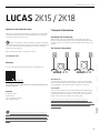 3
3
-
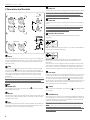 4
4
-
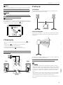 5
5
-
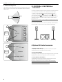 6
6
-
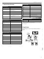 7
7
-
 8
8
-
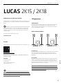 9
9
-
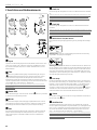 10
10
-
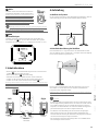 11
11
-
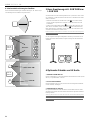 12
12
-
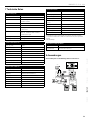 13
13
-
 14
14
-
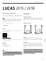 15
15
-
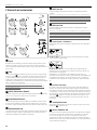 16
16
-
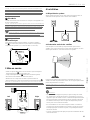 17
17
-
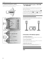 18
18
-
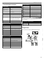 19
19
-
 20
20
-
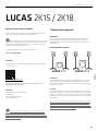 21
21
-
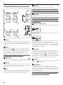 22
22
-
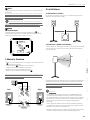 23
23
-
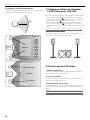 24
24
-
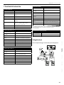 25
25
-
 26
26
-
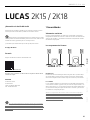 27
27
-
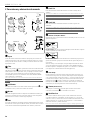 28
28
-
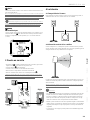 29
29
-
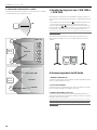 30
30
-
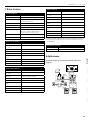 31
31
-
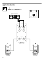 32
32
-
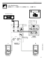 33
33
-
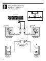 34
34
-
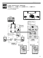 35
35
-
 36
36


HK Audio Lucas 2K18 Manual de usuario
- Categoría
- Altavoces de la barra de sonido
- Tipo
- Manual de usuario
- Este manual también es adecuado para
en otros idiomas
- français: HK Audio Lucas 2K18 Manuel utilisateur
- italiano: HK Audio Lucas 2K18 Manuale utente
- English: HK Audio Lucas 2K18 User manual
- Deutsch: HK Audio Lucas 2K18 Benutzerhandbuch
Artículos relacionados
-
HK Audio SOUNDCADDY ONE Manual de usuario
-
HK Audio Lucas Nano 605 FX El manual del propietario
-
-
-
-
-
HK Audio Lucas Nano 608i Manual de usuario
-
HK Audio Lucas Nano 302 Manual de usuario
-
-
HK Audio Linear Manual de usuario