Nobles Scout 7 Instrucciones de operación
- Tipo
- Instrucciones de operación

BATTERY SWEEPER
Operator’s Manual (EN)
Manual del operario (ES)
Manuel de l’opérateur (FR)
Model Part No.:
1251274 - Sweeper [Scout 7]
To view, print or download
the parts manual, visit:
www.nobles.com/manuals
www.nobles.com PLDC04332
Rev. 05 (03-2022)
SCOUT 7
TM

EN TRANSLATION OF ORIGINAL INSTRUCTIONS
TECHNICAL DATA AND CHARACTERISTICS ......................................................................................................2
WARNINGS ..............................................................................................................................................................3
SAFETY MEASURES ..............................................................................................................................................3
SAFETY LABELS ....................................................................................................................................................4
SERIAL NUMBER LABEL LOCATION ...................................................................................................................5
INTRODUCTION ......................................................................................................................................................5
UNPACKING ............................................................................................................................................................5
PREPARING THE MACHINE ..................................................................................................................................5
Fitting the side brush ...................................................................................................................................5
Fitting the handle ..........................................................................................................................................5
Preparation, installation and replacement of the battery .........................................................................6
ADJUSTMENT CONTROLS ....................................................................................................................................6
START-UP ................................................................................................................................................................6
INSTRUCTIONS FOR CORRECT OPERATION .....................................................................................................7
TAKING OUT THE DEBRIS HOPPER FOR CLEANING .......................................................................................7
)URQWELQ¿J ............................................................................................................................................7
5HDUELQ)LJ .............................................................................................................................................7
ROUTINE MAINTENANCE ......................................................................................................................................7
BATTERY MAINTENANCE .....................................................................................................................................8
Recharging the battery .................................................................................................................................8
BATTERY CHARGER SETTINGS ...........................................................................................................................8
BATTERY CHARGER ANOMALIES .......................................................................................................................8
FILTER MAINTENANCE ..........................................................................................................................................9
&OHDQLQJWKHSUH¿OWHU ...................................................................................................................................9
&OHDQLQJWKH¿OWHU .........................................................................................................................................9
5HSODFLQJWKH¿OWHU .......................................................................................................................................9
REPLACING AND ADJUSTING THE SIDE BRUSH ...............................................................................................9
REPLACING AND ADJUSTING THE CENTRE BRUSH ........................................................................................9
REPLACING AND ADJUSTING THE BELT ............................................................................................................10
Replacing the side brush belt ......................................................................................................................10
Replacing the drive belt ...............................................................................................................................10
REPLACING THE FLAPS .......................................................................................................................................10
2XWHUVLGHÀDSV .............................................................................................................................................10
,QQHUVLGHÀDSV .............................................................................................................................................10
&HQWUHÀDS .....................................................................................................................................................10
REPLACING AND ADJUSTING THE CABLES ......................................................................................................11
Replacing the drive cable ............................................................................................................................11
Replacing the side brush lifting cable ........................................................................................................11
CIRCUIT BRAKERS ................................................................................................................................................11
TROUBLESHOOTING TABLE ................................................................................................................................11
SCRAPPING THE MACHINE ..................................................................................................................................12
RECOMMENDED SPARE PARTS LIST ..................................................................................................................12
TABLE OF CONTENTS
Copyright © 2019 Tennant Company. All rights reserved.
Tennant Company
10400 Clean Street
Eden Prairie, MN 55344-2650
Phone: (800) 553- 8033
www.tennantco.com
- 1 -

EN TRANSLATION OF ORIGINAL INSTRUCTIONS
TECHNICAL DATA AND CHARACTERISTICS
DESCRIPTION
Maximum width mm 740
inches 29
Maximum length mm 1245
inches 49
Maximum height clearance with handle mm 960
inches 37.75
Cleaning width with centre brush mm 500
inches 19.68
Cleaning width with centre brush and side brush mm 700
inches 28
Weight with battery kg 121
lbs 266.76
Front debris bin capacity l45
ft31.6
Operating autonomy h<3
Filtering area m² 1.03
ft211.08
Filtration HႈFLHQW IRU SDUWLFOHV XS WR
microns
Productivity (for Hour) Theoretically Max. m2/h 2601
ft2/h 28000
Productivity (for Hour) Estimate Coverage m2/h 2508
ft2/h 27000
Installed power / current 710W / 59A
Battery type (maintenance-free) 12V 140Ah (C20)
Sound pressure, LpA 70 dBA
Measurement uncertainty, kpA 3.0 dBA
Sound power, LwA,g 80 dB
Vibration level (hand), ahv 1.1 m/sec2
Measurement uncertainty, k 0.5 m/sec2
- 2 -

EN TRANSLATION OF ORIGINAL INSTRUCTIONS
WARNINGS
This machine is intended for commercial use only. Its intended
purpose is to collect dirt, dry waste and dust from dry, paved or
carpeted surfaces.
It must not be used for any other purposes. Do not use the machine
to pick up liquids, hazardous or toxic materials.
Operators are required to read, understand and comply with the
following warnings.
In this manual, the warning symbol shown below and the term
“SAFETY WARNING” are used with the following meanings:
WARNING: warns of dangers or dangerous proce-
dures that may cause serious injuries or death.
SAFETY WARNING: indicates the procedures to be followed
for the safe use of the machine.
Failure to comply with these warnings may be the cause of injuries,
HOHFWULFVKRFN¿UHRUH[SORVLRQV
WARNING: Do not operate the machine in the pres-
HQFHRIÀDPPDEOHOLTXLGVRUYDSRXUVRUFRPEXV-
tible dusts.
The machine is not equipped with explosion-proof motors. The
sparks generated in the electric motors when starting and during
RSHUDWLRQPD\FDXVH¿UHRUH[SORVLRQLIWKHPDFKLQHLVXVHGLQWKH
SUHVHQFHRIÀDPPDEOHOLTXLGVYDSRXUVRUFRPEXVWLEOHGXVWV
:$51,1*'RQRWSLFNXSWR[LFRUÀDPPDEOHPDWH-
rials, burning or smouldering waste.
WARNING: The batteries emit hydrogen.
.HHS DZD\ IURP VSDUNV DQG RSHQ ÀDPHV /HDYH
the battery compartment open while charging.
WARNING: Do not charge the batteries if the char-
ger’s power cable appears damaged. Do not mod-
ify the plug.
If the battery charger cable is damaged or broken, have it replaced
E\WKHPDQXIDFWXUHUDQDXWKRULVHGVHUYLFHFHQWUH RUDTXDOL¿HG
technician.
WARNING: Before carrying out any work on the
machine, disconnect the battery cables and unplug
the charger’s power cable.
SAFETY WARNINGS: Do not use the machine on wet surfac-
es. Do not expose the machine to rain.
The machine must be kept indoors at all times
The following information indicates potentially dangerous
conditions for the operator or the machine.
SAFETY MEASURES
Do not use the machine:
• ,QWKHSUHVHQFHRIÀDPPDEOHRUH[SORVLYHVXEVWDQFHV
• Unless trained and authorised.
• Without having read the operator manual carefully.
• If the machine is not in perfect conditions.
• ,QWKHDEVHQFHRIDELQDQGRU¿OWHUV
Battery charger;
• Make sure that the power socket used for the battery charger
is connected to a suitable earth system and protected by
thermal overload and residual current circuit breakers.
• Make sure the electrical characteristics of the battery charger
(voltage, frequency, absorbed power) given on the rating
plate are the same as those of the mains power supply.
Before starting the machine:
• Make sure the safety devices are present and are functioning
correctly.
When the machine is running:
• Do not pick up burning or smouldering waste, such as
cigarettes, matches or embers.
• Do not use the machine to pick up liquids.
• Report any damage or faults immediately.
• Proceed slowly on sloping and slippery surfaces.
• Do not leave the machine unattended or on sloping surfaces.
• Do not use the machine to pick up wires, ropes, straps or
similar materials.
• Make sure the work area is well lit.
• Keep the machine out of the reach of children.
• Do not use the machine to transport people or things.
• In dusty environments, wear protective glasses and gloves.
Before leaving the machine or before carrying out maintenance:
• 6WRSWKHPDFKLQHRQÀDWDQGGU\ÀRRULQJ
• 7XUQWKHPDFKLQHRႇ
During maintenance and repair work:
• Keep away from moving parts. Do not wear jackets, shirts
or clothes with sleeves that may get caught in parts of the
machine.
• Before working on the machine, disconnect the battery and
the charger plug.
• Use original or approved spare parts.
• 5HSDLUVPXVWEHSHUIRUPHGE\DTXDOL¿HGWHFKQLFLDQ
• Do not modify the machine in any way.
• When handling the battery or battery cables, wear protective
gloves and goggles.
• Avoid contact with battery acid.
• Do not operate the machine on slopes greater than 2%
When transporting the machine:
• 7XUQWKHPDFKLQHRႇ
• Request assistance to lift the machine.
• )RU ORDGLQJXQORDGLQJ RQWRRႇ RI D WUXFN RU WUDLOHU XVH D
suitable ramp.
• Secure the machine to the truck or trailer using straps.
- 3 -

EN TRANSLATION OF ORIGINAL INSTRUCTIONS
SAFETY LABELS
6DIHW\ODEHOVDUHDႈ[HGWRWKHPDFKLQH,IGDPDJHGWKHVHPXVWEHUHSODFHG
WARNING! RISK OF ENTANGLEMENT
WARNING! RISK OF ACID BURNS
WARNING! RISK OF BURNS
MAXIMUM SLOPE
OPERATOR MANUAL, INSTRUCTIONS FOR USE
READ THE OPERATOR'S MANUAL
DIRECT CURRENT SYMBOL
CLASS III APPLIANCE. AN APPLIANCE IS IDENTIFIED AS CLASS III WHEN
ITS EXPLOSION-PROOF PROTECTION IS BASED ON THE FACT THAT
THERE ARE NO VOLTAGES HIGHER THAN THE ULTRA-LOW SAFETY
EXTRA-LOW VOLTAGE (SELV). THIS MEANS IN PRACTICE THAT THE
APPLIANCE IS POWERED BY A BATTERY OR A SELV TRANSFORMER.
SPECIAL WASTE. DO NOT DISPOSE OF AS NORMAL WASTE.
SAFETY LABEL. THE SAFETY LABEL APPEARS ON THE MACHINE IN THE
LOCATION INDICATED. REPLACE LABEL IF IT IS MISSING OR IF IT BECOMES
DAMAGED OR ILLEGIBLE.
WARNING! RISK OF ABRASION OR ENTANGLEMENT BY TOUCHING THE
BRUSH IN ROTATION
- 4 -

EN TRANSLATION OF ORIGINAL INSTRUCTIONS
SERIAL NUMBER LABEL LOCATION
Make sure that the machine is equipped with a rating plate showing
WKHVHULDOQXPEHUSRVLWLRQHGDVVKRZQLQ¿J,IWKLVLVQRWWKH
case, notify the dealer immediately.
PREPARING THE MACHINE
Fitting the side brush
• Move the brush raising lever (pos. 1 Fig. 3) to the “0” position..
• Unscrew the screw on the side brush shaft.
• Place the brush on the shaft (Fig. 2).
• Tighten the screw complete with washer.
INTRODUCTION
This instruction manual contains guidelines and practical
information concerning the safety, use, adjustment and
maintenance of the machine. The machine has been designed
DQGEXLOWWRRႇHU WKHEHVWLQWHUPVRI SHUIRUPDQFHFRPIRUW DQG
HDVHRIXVHLQDYDULHW\RIGLႇHUHQWFRQGLWLRQV
Before delivery, the machine has been checked at our factory
and by our dealer to guarantee that it is handed over to you in
perfect working order. To maintain the machine in this condition
and ensure problem-free operation, strictly follow the routine
maintenance instructions given in the manual.
UNPACKING
Unpack the machine with care, avoiding any manoeuvres that
may damage it; once unpacked, check that all of the parts are
intact. If you notice any damage, DO NOT use the machine and
contact your dealer. Due to packaging and transport requirements,
some parts and optionals may be supplied separately; for correct
assembly, follow the instructions given in the corresponding
paragraphs of this booklet.
Contents of the packaging:
1 Machine
1 Side brush
1 Instruction booklet
1 Warranty
1 Tool kit:
2 Ignition keys
1 Battery
If you notice that any of the above are missing, contact the dealer
immediately.
Make sure the packaging materials (bags, boxes, pallets, hooks,
etc.) are put away, out of the reach of children.
To avoid losing them during transport, the ignition
keys are placed inside the document envelope.
Fitting the handle
• 5HPRYHWKHWRSFRZOLQJWRDFFHVVWKHKDQGOH¿[LQJVFUHZV
• Lift the handle to the operating position (pos. 1 Fig. 2/A).
• 7LJKWHQWKHKDQGOH¿[LQJVFUHZVSRV)LJ$XVHWKHWRRO
supplied with the machine).
NOTES
FIG. 1
Fig. 2
Fig. 2/A
12
- 5 -

EN TRANSLATION OF ORIGINAL INSTRUCTIONS
Preparation, installation and replacement of the battery
FOR YOUR SAFETY: Wear protective gloves and eye protection
when handling the battery and battery cables. Avoid contact with
battery acid.
Contact Tennant or distributor for battery replacement
recommendations.
Max. battery dimensions: 18 cm (7.00 in) P x 32 cm (12.50 in) L x
24 cm (9.38 in ) H.
IMPORTANT: The on-board battery charger settings MUST BE
UHFRQ¿JXUHG ZKHQ FKDQJLQJ WR D GLႇHUHQW W\SH RI EDWWHU\ LH
LIQUID (lead-acid) or SEALED (gel). See BATTERY CHARGER
SETTINGS
The battery charger is factory-set for Gel/AGM batteries.
Installing the battery:
• Remove the ignition key from the machine.
• Turn the front cowling and remove the top cowling to access
the battery compartment.
• Carefully place the battery in the compartment with the
battery terminal facing the rear of the machine and connect
the cables to the battery: RED to the POSITIVE pole (+),
BLACK to the NEGATIVE (-) (Fig 2/B).
• Secure the battery with the strap.
• Charge the battery. See RECHARGING THE BATTERY
ADJUSTMENT CONTROLS
1) Side brush control lever: moving the lever to “I” position, the
side brush moves to the working position and starts rotating. To
stop the brush, return the lever to the “0” position.
2) Key switch: machine power supply.
3) Charge status indicator: displays the battery charge when the
machine is running.
4) Drive lever: pulling this lever engages the transmission and the
machine that starts to move forward.
5) Flap lever: pulling this lever allows the centre brush to pick up
bulky objects.
(OHFWULF¿OWHUVKDNHUEXWWRQ
7) Suction switch.
START-UP
SAFETY WARNINGS: The machine must only be used by
trained and authorised personnel.
'RQRWSLFNXSOLTXLGVRUOHDYHWKHPDFKLQHXQDWWHQGHG5H-
move the ignition key before leaving the machine and keep it
out of the reach of children.
SAFETY WARNING: Do not use the machine on wet surfaces.
To start the machine, proceed as follows:
• Check that the side brush pos. 1 Fig 3 is in the “0” position.
• Turn the key switch to “I” position, pos. 2 Fig. 3.
• After turning the key, wait about 10 seconds until the machine
starts running. Check on the indicator pos. 3 Fig. 3 that the
battery is fully charged before starting work, otherwise charge
the battery.
• Activate the suction motor by moving the switch in pos. 7 Fig.
3 to “I”.
7XUQRႇWKHVXFWLRQPRWRUZKHQXVLQJWKHPDFKLQH
when being moved by moving the switch in pos. 7
Fig. 3 to “0”.
• Pull the drive lever pos. 4 Fig. 3 and carry out the cleaning
operations. If necessary, operate the lever pos. 1 Fig. 3,
moving it to position “I” to engage the side brush. After having
¿QLVKHGZRUNPRYHWKHVLGHEUXVKOHYHULIXVHGWRSRVLWLRQ
³´ VZLWFK WKH PDFKLQH Rႇ DQG UHPRYH WKH NH\V IURP WKH
control panel.
An automatic device prevents the machine from working beyond a
certain battery discharge threshold.
Once this limit is reached, the machine stops and must be
recharged in order to resume operation.
NOTES
Fig. 2/B
1
5
26-7
3
4
Fig. 3
- 6 -

EN TRANSLATION OF ORIGINAL INSTRUCTIONS
INSTRUCTIONS FOR CORRECT OPERATION
$IWHU KDYLQJ VWDUWHG WKH PDFKLQH WKH ¿UVW WLPH LW LV UHDG\ WR
start working as a sweeper. To achieve the highest performance
from the sweeper at all times, it is recommended to follow some
instructions aimed at keeping the machine in the best conditions
and minimising the risk of damage.
Important:
• Do not pick up wires, ropes, straps or other similar materials.
• In the presence of bulky or particularly light objects (paper,
leaves, etc.), raise the front of the machine by pushing on the
handle while picking up the waste.
• 8VHWKHÀDSUDLVLQJOHYHUWRFROOHFWEXON\LWHPV
• 6KDNH WKH ¿OWHU DIWHU KDYLQJ ¿QLVKHG ZRUN VHH ),/7(5
MAINTENANCE).
• Keep the centre brush correctly adjusted (see CENTRE
BRUSH ADJUSTMENT).
TAKING OUT THE DEBRIS HOPPER FOR CLEANING
WARNING: Before taking out the hopper, make
VXUHDOOPDFKLQHIXQFWLRQVDUHWXUQHGRႇ7KLVLVWR
avoid the possibility of touching the rotating brush.
WARNING: ALL WASTE COLLECTION OPERATIONS MUST
BE PERFORMED IN COMPLIANCE WITH THE RELEVANT
LAWS IN FORCE.
)URQWELQ¿J
• Turn/open the front cover.
• Lift and turn the two bin locking devices.
• Hold the bin by the handle/handles and remove it by pulling
it upwards.
• Empty the bin.
To replace the bin:
• Insert the bin into the machine.
• Turn and lower the two locks.
• Turn/close the front cowling.
5HDUELQ)LJ
• Lift and turn the two rear bin locking devices.
• Hold the rear bin by the handle and pull it out of the machine.
• Empty the bin.
To replace the bin:
• Insert the bin into the machine.
• Turn and press the two locks.
ROUTINE MAINTENANCE
SAFETY WARNINGS: Any repairs must be performed by a
TXDOL¿HGWHFKQLFLDQ8VHRULJLQDORUDSSURYHGVSDUHSDUWV
WARNING: Before carrying out any work on the
machine, disconnect the battery cables and unplug
the charger’s power cable.
WARNING: All maintenance operations must be
SHUIRUPHGZLWKWKHPDFKLQHRႇ
CHECKS
On delivery
Every 10 hours
Every 50 hours
Every 100 hours
Every 200 hours
Loosening of belts X
Tightness of the nuts and screws X
Conditions of the brushes X
Check tightness of the gaskets X
Check that all functions are active XXXX
5HSODFHWKH¿OWHU X
Fig. 4
FIG. 5
Fig. 5/A
- 7 -

EN TRANSLATION OF ORIGINAL INSTRUCTIONS
BATTERY MAINTENANCE
The battery must always be kept clean and dry. Terminals and
poles must be kept clean at all times. Liquid battery (lead-acid),
every 10 hours remove the caps and check the electrolyte level;
if necessary top up with distilled water to cover the plates, do not
RYHU¿OO PD[LPXP PP DERYH WKH SODWHV 5HPHPEHU WKDW WKH
room where this operation is carried out must be well ventilated;
NHHSDZD\IURPQDNHGÀDPHVGRQRWVPRNHGXULQJWKLVRSHUDWLRQ
The battery has an operating time that should exceed 2 hours; if
this turns out to be considerably shorter, check:
• that the brushes are not blocked by wires, ropes and straps;
• that the battery has been fully recharged.
Recharging the battery
Battery life depends on routine maintenance and the level of
discharge. Do not let the battery charge fall below the limit
indicated by the lights in pos. 3 Fig. 3.
Once the max. discharge limit has been reached, the machine will
stop and must be recharged before it can be used again.
Charge lights on the control panel
Green light: The battery is charged.
Yellow light: The battery is discharging; recharge as soon as
possible.
Red light: The battery is discharged. DO NOT continue using the
machine, recharge it immediately.
To recharge the battery
WARNING: The batteries emit hydrogen. Keep
DZD\IURPVSDUNVDQGQDNHGÀDPHV/HDYHWKHEDW-
tery compartment open while charging.
SAFETY WARNINGS: Avoid contact with the battery acid dur-
ing maintenance and repair operations. When handling the
battery or battery cables, wear protective gloves and goggles.
• When not in use, keep the machine in a well-ventilated place.
• :KHQ WKH PDFKLQH LV Rႇ FRQQHFW WKH FKDUJHU FDEOH )LJ
$&KHFN WKDW WKHLQSXWYROWDJH VSHFL¿HG IRUWKH EDWWHU\
charger is compatible with the available power supply voltage.
• Before recharging, make sure that the charger settings
are correct. The battery charger is factory-set for Gel/AGM
batteries. (See BATTERY CHARGER SETTINGS).
• If there is a problem with the battery charger, an error code
will be displayed (see the manual for the battery charger
supplied with the machine).
• During the charging cycle, the charger lights will change
FRORXUIURPUHGWR\HOORZDQG¿QDOO\JUHHQ$WWKHHQGRIWKH
charging cycle, when the green light is on, disconnect the
charger cable.
WARNING: Never disconnect the battery when re-
charging. This may cause sparks.
BATTERY CHARGER SETTINGS
IMPORTANT: The battery charger supplied is factory-set for Gel/
AGM batteries. For lead-acid batteries, the dipswitches on the
EDWWHU\ FKDUJHU PXVW EH VHW DV VKRZQ LQ WKH IROORZLQJ ¿JXUH
otherwise the battery may be damaged.
The dipswitches are located behind the black round cover (Fig.
5/B).
BATTERY CHARGER ANOMALIES
<HOORZ/('ÀDVKLQJ Unsuitable battery or battery
not connected or output short
circuit.
5HGDQG<HOORZ/('ÀDVKLQJ Battery voltage higher than
4.0V but lower than 1.4V for
Cell.
Red and Green LED ON Internal overtemperature error.
5HG/('ÀDVKLQJ Safety timer exceeded.
Internal short circuit (Output
overcurrent)
Red, Yellow and Green LED
ÀDVKLQJHYHU\VHFRQG
$OOFKDUJLQJSUR¿OHSDUDPHWHUV
are not programmed to the
EEPROM of the charger.
Red, Yellow and Green LED
ÀDVKLQJFRQWLQXRXVO\
7KH FKDUJLQJ SUR¿OH
parameters of the selected
FKDUJLQJ SUR¿OH DUH QRW
programmed to the EEPROM
of the charger or charging
SUR¿OHQRWDFWLYH
SW2
DP2
ON 13A DEFAULT
OFF 10A
SW1 SW2
DP1 DP2 DP1
OFF OFF OFF IUIa Acido generica
OFF OFF ON IUIa/O Acido generica con mant.
OFF ON OFF IUIa Acido "Trojan"
OFF ON ON IUUO Gel/AGM Generica DEFAULT
ON OFF OFF IUIa Gel "Exide Sonnenschin"
ON OFF ON IUIa AGM "Discover"
ON ON OFF IUIa Gel AGM Reliant AGM "Trojan"
ON ON ON IUoU AGM Fullriver
DIP- SWITCH (SW1-SW2)
ON ON
OFF OFF
DP1 DP2
SW1
ON ON
OFF OFF
DP1 DP2
SW2 ON
Fig. 5/B
- 8 -

EN TRANSLATION OF ORIGINAL INSTRUCTIONS
FILTER MAINTENANCE
:$51,1*%HIRUHWDNLQJRXWWKHGXVW¿OWHURUSUH
¿OWHUPDNHVXUHDOOPDFKLQHIXQFWLRQVDUHWXUQHG
Rႇ7KLVLVWRDYRLGWKHSRVVLELOLW\RIWRXFKLQJWKH
rotating brush.
&OHDQLQJWKHSUH¿OWHU
&OHDQWKHSUH¿OWHUHYHU\GD\
• Remove the rear bin
• 5HPRYHWKHSUH¿OWHUIURPWKH¿OWHU
• &OHDQWKHSUH¿OWHUZLWKDYDFXXPFOHDQHURUZDVKLWXQGHU
running water and allow it to dry completely before replacing
it in the machine.
&OHDQLQJWKH¿OWHU
7KHVXFWLRQ¿OWHUPDNHVDPDMRUFRQWULEXWLRQWRWKHHႈFLHQF\RI
the whole machine.
3URSHU ¿OWHU PDLQWHQDQFH ZLOO DOORZ \RX WR REWDLQ WKH EHVW
performance from your machine. If the sweeper begins to raise
GXVWDVLWVZHHSVFKHFNWKHFRQGLWLRQRIWKHVXFWLRQ¿OWHU
7KHVXFWLRQ¿OWHUFDQEHFOHDQHGDVIROORZV
• DXWRPDWLF¿OWHUFOHDQLQJKROGWKH¿OWHUVKDNHUEXWWRQSRV
Fig. 3 in position “II” for a few seconds. Repeat this operation
while using the machine. This operation should be performed
at the end of every working cycle. If the machine is used
in a dusty environment (e.g. sawmills, warehouses where
YHKLFOHV RSHUDWH HWF PDNH VXUH WR XVH WKH ¿OWHU VKDNHU
more frequently.
• PDQXDOO\FOHDQLQJWKH¿OWHULIWKH¿OWHUVKDNHULVQRWHႇHFWLYH
LQ FOHDQLQJ WKH ¿OWHU DQG LQ DQ\ FDVH HYHU\ RSHUDWLQJ
KRXUVFOHDQWKH¿OWHUPDQXDOO\%HIRUHFDUU\LQJRXWDQ\W\SH
RIZRUNRQWKHPDFKLQHPDNHVXUHWKDWLWLVVZLWFKHGRႇDQG
that all of the functions are deactivated. To do this, turn the
key switch to position “0”.
• Remove the rear bin.
• 5HPRYHWKHSUH¿OWHUIURPWKH¿OWHU
• Open the handles (pos. 1)
• Turn the catches (pos. 2) 180°
• 5HPRYHWKH¿OWHUSRV
• &OHDQWKH¿OWHUZLWKDYDFXXPFOHDQHURUDOWHUQDWLYHO\EORZ
WKH¿OWHUZLWKFRPSUHVVHGDLUSUHVVXUHQRWH[FHHGLQJ
EDUVLQWKHRSSRVLWHGLUHFWLRQWRWKHDLUÀRZDWDGLVWDQFH
of more than 20 cm (8 inches).
• 5HSODFHWKH¿OWHUWKHDUURZSRVPXVWEHSRLQWLQJLQ
WKHGLUHFWLRQRIDLUÀRZIURPWKHRXWVLGHWRWKHLQVLGHRI
WKHPDFKLQHWKHQ¿WWKHSUH¿OHU
5HSODFLQJWKH¿OWHU
7KH¿OWHUPXVWEHUHSODFHGHYHU\RSHUDWLQJKRXUV
Follow the instructions shown in Fig. 6:
• Remove the rear bin
• Open the handles (pos. 1)
• Turn the catches (pos. 2) 180°
• 5HSODFHWKH¿OWHUSRV
• 7KHDUURZSRVPXVWEHSRLQWLQJLQWKHGLUHFWLRQRIDLUÀRZ
from the outside to the inside of the machine.
:$51,1*LQVHUWWKH¿OWHULQWKHGLUHFWLRQVKRZQSRV)LJ
:KHQ UHSODFLQJ WKH ¿OWHU PDNH VXUH WKHUH LV SHUIHFW WLJKWQHVV
EHWZHHQWKH¿OWHUDQGWKHJDVNHWV
PLEASE CAREFULLY FOLLOW THE REGULATIONS IN FORCE
FOR WASTE DISPOSAL.
REPLACING AND ADJUSTING THE SIDE BRUSH
Replacement
After lifting the front of the machine, to replace the side brush,
XQVFUHZ WKH VFUHZ )LJ WKDW ¿[HV WKH EUXVK DQG UHPRYH WKH
brush. Replace it with the new brush and then tighten the screw,
complete with washer.
Adjustment
The height of the side brush is factory-adjusted for hard surfaces
(ceramic tile or natural stone). If the machine is going to operate
RQ D VRIW VXUIDFH ¿WWHG FDUSHW DGMXVW WKH EUXVK EHIRUH XVLQJ
LW IRU WKH ¿UVW WLPH UHIHUULQJ WR WKH LQGLFDWLRQV RQ WKH ODEHO DQG
proceeding as follows.
Turn the front cowling and remove the front bin.
The side brush is adjusted by loosening the screws pos. 1 Fig. 6/A
and manually positioning the brush at the desired height along the
slots. Once having determined the correct height, tighten the two
screws.
REPLACING AND ADJUSTING THE CENTRE BRUSH
Replacement (Fig.6/B)
To replace the centre brush, turn the front cowling and remove
WKHIURQWELQIURPWKHPDFKLQHXQVFUHZWKHIRXU¿[LQJVFUHZVDQG
remove the brush. When reassembling the new brush, make sure
the brush is placed in the right direction so as to move the dirt
towards the centre of the machine.
Fig. 6
Fig. 6/A
1
1
3
24
Hard
Floor Soft Floor
- 9 -

EN TRANSLATION OF ORIGINAL INSTRUCTIONS
Adjusting the centre brush.
7KHFHQWHUEUXVKKHLJKWLVIDFWRU\DGMXVWHGIRUKDUGÀRRUVHWWLQJ
)LJ',IXVLQJWKHPDFKLQHRQVRIWÀRRU&DUSHWORRVHQWKH
locking nut pos. 1 Fig. 6/D and turn the adjustment knob pos.
2 Fig. 6/D two full turns clockwise to decrease brush pressure.
Retighten locking nut.
For proper brush adjustment, the bristles should slightly bend
DJDLQVW WKH ÀRRU VXUIDFH $V WKH EUXVK ZHDUV LW¶V LPSRUWDQW WR
increase the brush pressure to maintain optimum sweeping
performance.
Too much brush pressure may prematurely wear
brush and decrease battery run time. When replac-
ing a worn brush, it’s important to readjust the set-
ting back to “0”.
REPLACING AND ADJUSTING THE BELT
To prepare the machine for replacement of one or more belts,
proceed as follows:
• turn the front cowling, remove the top cowling and the front
bin.
• DIWHUKDYLQJWDNHQRႇWKHOHIWZKHHOXQVFUHZWKHVFUHZVWKDW
¿[WKHEXPSHUDQGWKHULJKWVLGHFRYHUDQGUHPRYHWKHP
Replacing the side brush belt
• Remove the belt pos. 7 Fig. 7 from the pulley pos. 6 Fig. 7.
• 8QVFUHZWKH¿[LQJSLQSRV)LJDQGUHOHDVHWKHKRRNVRQ
the side arm pos. 9 Fig. 7 from the idle toothed ring.
• Remove the belt pos. 7 from the side arm pos. 9 Fig. 7.
• Replace the belt.
• Reattach the side arm pos. 9 Fig. 7 to the idle toothed ring.
• Retighten the pin pos. 8 Fig. 7.
• Reposition the belt pos. 7 Fig. 7 on the pulley pos. 6 Fig. 7.
Replacing the drive belt
• Remove the belt pos. 1 Fig. 7.
REPLACING THE FLAPS
2XWHUVLGHÀDSV
7RUHSODFHWKHVLGHÀDSVSRV)LJWDNHRႇWKHEDFNZKHHOV
8QVFUHZWKHVFUHZV¿[LQJWKHÀDSVWRWKHFKDVVLVSRV)LJ
DQGUHSODFHZLWKQHZÀDSV
,QQHUVLGHÀDSV
7RUHSODFHWKHLQQHUVLGHÀDSVSRV)LJOLIWWKHIURQWRIWKH
PDFKLQHDQGXQVFUHZWKHVFUHZVSRV)LJWKDW¿[WKHÀDSV
WRWKHFKDVVLV5HSODFHZLWKQHZÀDSV
&HQWUHÀDS
• 7DNHRႇWKHEDFNZKHHOVDQGWKHFRUUHVSRQGLQJVLGHFRYHUV
• Remove the drive pulley.
• Remove the rear bin.
• 8QVFUHZWKHWZRÀDS¿[LQJSLQVSRV)LJRQWKHVLGHV
of the chassis.
• +ROGWKHÀDSSRV)LJDQGSXOOLWWRZDUGVWKHRXWVLGHRI
the machine.
Reassembly:
• ,QVHUWWKHÀDSLQWKHVDPHGLUHFWLRQDVLWZDVUHPRYHG
• Insert the two references in the corresponding holes.
• 7LJKWHQWKH¿[LQJSLQVDQGUHDVVHPEOHWKHPDFKLQH
NOTE
ETET16859
2
1
Fig. 6/D
Fig. 7
Fig. 6/B
- 10 -

EN TRANSLATION OF ORIGINAL INSTRUCTIONS
REPLACING AND ADJUSTING THE CABLES
Replacing the drive cable
To replace the drive cable, proceed as follows:
•Remove the top cowling from the machine.
•Loosen the dowel on the cable locking pin.
• Pull the cable out of the locking pin and completely out of the
drive handle.
To reassemble the cable:
• Insert one end of the cable into the adjustment screw on the
drive handle (the end without the spherical cable lock).
•Insert the cable into the sheath.
•Attach the spherical cable lock to the handle.
•5XQWKHFDEOH¿UVWWKURXJKWKHUHJLVWHUDWWDFKHGWRWKHFKDVVLV
and then through the cable locking pin.
•Tighten the locking dowel.
To adjust the cable, use the two registers until obtaining the
desired position.
Replacing the side brush lifting cable
To replace the side brush lifting cable, proceed as follows:
•Remove the top cowling from the machine and the front bin.
•Remove the front bumper, the right-side wheel and the right-
side cover.
•Loosen the cable clamp.
•/RRVHQWKHGRZHORQWKH¿[LQJSLQ
• Remove the handle from the support and open it.
•Remove the cable from the two sheaths.
To reassemble the cable:
•Place the cable in the handle.
•&ORVHWKHKDQGOHDQG¿[LWWRLWVVXSSRUW
•Insert the cables into the sheaths.
• Lock one end of the cable with the clamp and the other end
ZLWKWKH¿[LQJSLQ
To adjust the cable, use the two registers until obtaining the
desired position.
TROUBLESHOOTING TABLE
FAULT CAUSE SOLUTION
The centre brush
GRHVQ¶WWXUQ
Belt broken Replace
Gear motor
damaged Contact service
centre
Wire detached Contact service
centre
Breaker tripped Reset
The side brushes
do not rotate. Belt broken Replace
7KHEDWWHU\GRHVQ¶W
hold its charge
No liquid (for lead-
acid battery) Top up
Loose terminal Tighten.
Dust comes out
of fan
%URNHQ¿OWHU Replace
Filter positioned
incorrectly Reposition
Worn gaskets Replace
The brushes wear
out too quickly Brushes pressed
too hard Adjust
Dust released
when working
:RUQÀDSV Replace
Filter clogged Clean
The suction motor
LVQ¶WZRUNLQJ
Motor burned out Contact service
centre
Wire detached Contact service
centre
Breaker tripped Reset
The machine
GRHVQ¶WVWDUW
Battery terminals
detached Check
Batteries
discharged Recharge
Machine not
moving Breaker tripped Reset
CIRCUIT BREAKERS
The machine is equipped with circuit breaker type fuses. These are
resettable devices designed to protect the electrical circuits of the
PDFKLQHDJDLQVWWKHUPDORYHUORDGE\VKXWWLQJRႇWKHÀRZRIFXUUHQW
Once a circuit breaker has been tripped, allow time for the circuit to
cool down, then reset the breaker switch manually by pressing the
relative button.
,IWKHRYHUORDGFRQGLWLRQWKDWWULSSHGWKHEUHDNHULVVWLOODႇHFWLQJWKH
FLUFXLWWKHIXVHZLOOFRQWLQXHWRVKXWRႇWKHÀRZRIFXUUHQWXQWLOWKH
problem has been located and remedied. To access the fuses, tilt the
front hood forward and remove the top section.
Fig. 8
- 11 -
NOTE: Earlier models are equipped with replaceable fuses.

EN TRANSLATION OF ORIGINAL INSTRUCTIONS
RECOMMENDED SPARE PARTS LIST
Part No. WEAR PARTS
PMVR00248 BRUSH KIT, SWEEPER, SIDE, STANDARD
SPPV00051 BRUSH KIT, SWEEPER, MAIN [COMPLETE]
FTDP76065 FILTER, PAPER, MAIN
FTDP00004 FILTER KIT, DUST, PRE-FILTER
MPVR76042 SKIRT KIT, FLAPS (includes *)
MPVR75928 *SKIRT, FLAP, LEFT, BLACK
MPVR75922 *SKIRT, FLAP, RIGHT, BLACK
MPVR75927 *SKIRT, FLAP, INNER, GRAY
MPVR85933 *SKIRT, FLAP, BACKSIDE
MPVR87400 SKIRT, FLAP, MAIN FRONT
MPVR00731 SKIRT, FLAP, FRONT
1069835 CORD, POWER, CHARGER, 120V [NA]
989584 CORD, POWER, CHARGER, 100V [JP]
1044068 CORD, POWER, CHARGER, 230V [EU]
1026325 CORD, POWER, CHARGER, 240V [AUS]
1044069 CORD, POWER, CHARGER, 230V [UK]
Part No. SERVICE PARTS
1053408 BATTERY, AGM, 12VDC, 140AH/C20 [NA/
EXP/JP]
994201 BATTERY, GEL, 12VDC, 105AH/C5 [EU/JP]
BACA00278 CHARGER, BATTERY, CBHD1 12V 10A [S7]
RDGR75782 MOTOR, ELE, GEAR
MOCC75780 MOTOR, ELE, FAN, 12VDC, 77MMD
MPVR87013 CARBON BRUSH, BRUSH MOTOR
1017696 KEY SET, REPLACEMENT
MPVR75836 BUSHING, LEVER [BELT TIGHTNER]
LAFN75834 BUSHING, ROCKER
RTRT24661 CASTER, SWIVEL, 100MMD, BLACK
CUVR75814 BEARING, NEEDLE [HK 1012]
SFVR00002 BEARING, BALL, 0.34B
LAFN75826 RING, BRUSH, SIDE [TOOTHED]
LAFN75833 BUSHING, BEARING
LAFN75838 BUSHING, HEX
RTRT75989 WHEEL, 250D 55W BLACK
PMTR00008 WHEEL ASSY, RIGHT WITH BEARING [ S7]
PMTR00010 WHEEL ASSY, LEFT, WITH BEARING [S7]
CUVR75815 VR, BEARING, FLANGE [S7]
CUVR86373 BEARING, BALL [6000 2RS]
VEVR26677 IMPELLER, FAN, 200MMD
MECE75944 CIRCUITBOARD, MAIN
LAFN00188 BUSHING
MPVR00017 SIDE BRUSH LEVER
MOCC00500 MOTOR KIT, SHAKER [S7]
MTCG13166 BELT, DRIVE
MTCG85335 BELT, SIDE BRUSH, BLUE
KTRI75926 GASKET KIT, FILTER [4 PC]
KTRI86322 GASKET KIT, FRONT CONTAINER [3 PC]
GUGO00285 GASKET, REAR CONTAINER
CUVR71988 BEARING, BELT TENSIONER
CUVR00005 BEARING, BRUSH, MAIN
CUVR86893 BEARING, SIDE BRUSH
CUVR37344 BEARING, NEEDLE, WHEEL
CUVR37341 BEARING, NEEDLE, WHEEL
In the event of other malfunctions, contact the
dealer
NOTES
SCRAPPING THE MACHINE
If the machine is to be scrapped, please note that the batter-
ies CANNOT be considered ordinary waste, rather they must
be disposed of in accordance with the laws in force. As the
PDFKLQHLVDQDVVHPEO\RIVHYHUDOGLႇHUHQWSDUWVLWLVUHFRP-
mended to disassemble it and sort the parts into groups of
the same material, in accordance with the laws in force.
DO NOT USE ANY PART BEING SCRAPPED AS A SPARE
PART. IN THIS CASE TOO, KEEP ALL PARTS OUT OF THE
REACH OF CHILDREN.
- 12 -

ES TRADUCCIÓN DE LAS INSTRUCCIONES ORIGINALES
DATOS Y CARACTERÍSTICAS TÉCNICAS ...........................................................................................................2
ADVERTENCIAS .....................................................................................................................................................3
MEDIDAS DE SEGURIDAD ....................................................................................................................................3
ETIQUETAS DE SEGURIDAD .................................................................................................................................4
POSICIÓN DE LA PLACA DE CARACTERÍSTICAS ..............................................................................................5
INTRODUCCIÓN ......................................................................................................................................................5
DESEMBALAJE ......................................................................................................................................................5
PREPARACIÓN DE LA MÁQUINA .........................................................................................................................5
Montaje del cepillo lateral ............................................................................................................................5
Montaje del manillar .....................................................................................................................................5
Preparación, instalación y sustitución de la batería .................................................................................6
MANDOS DE REGULACIONES ..............................................................................................................................6
PUESTA EN MARCHA ............................................................................................................................................6
OPERACIONES PARA UN FUNCIONAMIENTO CORRECTO ..............................................................................7
EXTRACCIÓN DEL CAJÓN RECOLECTOR DE RESIDUOS ................................................................................7
&DMyQGHODQWHUR¿J .................................................................................................................................7
&DMyQWUDVHUR¿J .....................................................................................................................................7
MANTENIMIENTO ORDINARIO ..............................................................................................................................7
MANTENIMIENTO DE LA BATERÍA .......................................................................................................................8
5HFDUJDGHODEDWHUtD ....................................................................................................................................8
CONFIGURACIONES DEL CARGADOR DE BATERÍA .........................................................................................8
DESPERFECTOS DEL CARGADOR DE BATERÍA ...............................................................................................8
MANTENIMIENTO DEL FILTRO .............................................................................................................................9
/LPSLH]DGHOSUH¿OWUR ....................................................................................................................................9
/LPSLH]DGHO¿OWUR .........................................................................................................................................9
6XVWLWXFLyQGHO¿OWUR .....................................................................................................................................9
SUSTITUCIÓN Y REGULACIÓN DEL CEPILLO LATERAL ..................................................................................9
SUSTITUCIÓN Y REGULACIÓN DEL CEPILLO CENTRAL ..................................................................................9
SUSTITUCIÓN Y REGULACIÓN DE LAS CORREAS ...........................................................................................10
Sustitución de la correa del cepillo lateral .................................................................................................10
Sustitución de la correa de tracción ...........................................................................................................10
SUSTITUCIÓN DE LOS FLAPS ..............................................................................................................................10
Flaps laterales externos ...............................................................................................................................10
Flaps laterales internos ................................................................................................................................10
Flap central ....................................................................................................................................................10
SUSTITUCIÓN Y REGULACIÓN DE LOS CABLES ..............................................................................................11
Sustitución del cable de tracción ................................................................................................................11
Sustitución del cable de levantamiento del cepillo lateral .......................................................................11
FUSIBLES ................................................................................................................................................................11
TABLA DE FALLOS-CAUSAS-SOLUCIONES .......................................................................................................11
DESGUACE DE LA MÁQUINA ...............................................................................................................................12
PIEZAS DE REPUESTO RECOMENDADAS ..........................................................................................................12
ÍNDICE
Copyright © 2019 Tennant Company. Todos los derechos reservados.
Tennant Company
10400 Clean Street
Eden Prairie, MN 55344-2650
Phone: (800) 553- 8033
www.tennantco.com
- 1 -

ES TRADUCCIÓN DE LAS INSTRUCCIONES ORIGINALES
DATOS Y CARACTERÍSTICAS TÉCNICAS
DESCRIPCIÓN
Anchura máxima mm 740
pulgadas 29
Longitud máxima mm 1245
pulgadas 49
Altura máxima con manillar mm 960
pulgadas 37.75
Anchura de limpieza con cepillo central mm 500
pulgadas 19.68
Anchura de limpieza con cepillo central y cepillo lateral mm 700
pulgadas 28
Peso con batería kg 121
lbs 266.76
Capacidad cajón de residuos delantero L45
ft31.6
Autonomía de trabajo h<3
6XSHU¿FLH¿OWUDQWH m² 1,03
ft211.08
Filtración H¿FD]DOSDUDSDUWtFXODVKDVWD
5 micras
Productividad (por hora) Valor Teórico Máx m2/h 2601
ft2/h 28000
Productividad (por hora) Área estimada m2/h 2508
ft2/h 27000
Potencia instalada / Absorción 710W / 59A
Tipo de baterías (sin mantenimiento) 12V 140Ah (C20)
Presión acústica, LpA 70 dBA
Incertidumbre de las medidas, kpA 3.0 dBA
Potencia acústica, LwA,g 80 dB
Vibraciones mano, ahv 1.1 m/seg2
Incertidumbre de las medidas, k 0.5 m/seg2
- 2 -

ES TRADUCCIÓN DE LAS INSTRUCCIONES ORIGINALES
ADVERTENCIAS
Esta máquina está diseñada solo para uso comercial. Su función
HVEDUUHUODVXFLHGDGORVUHVLGXRVVHFRV\HOSROYRGHVXSHU¿FLHV
secas, pavimentadas o alfombradas.
1R GHEH XWLOL]DUVH SDUD RWURV ¿QHV 1R XWLOLFH OD PiTXLQD SDUD
aspirar líquidos, materiales peligrosos o tóxicos.
Los operadores deben leer, conocer y respetar las siguientes
advertencias.
En este manual, el símbolo de advertencia que se muestra a
continuación y la frase «ADVERTENCIA DE SEGURIDAD» se
XWLOL]DQFRQORVVLJXLHQWHVVLJQL¿FDGRV
$7(1&,Ï1DGYLHUWHVREUHSHOLJURVRSURFHGLPLHQ-
WRVSHOLJURVRVTXHSRGUtDQFDXVDUOHVLRQHVJUDYHV
o la muerte de personas.
ADVERTENCIA DE SEGURIDAD: indica los procedimientos
TXHVH GHEHQ VHJXLU SDUDXWLOL]DU OD PiTXLQD UHVSHWDQGROD
VHJXULGDG
El incumplimiento de dichas advertencias puede
causar lesiones, electrocución, descargas eléctricas, incendios
o explosiones.
$7(1&,Ï1QRDFFLRQHODPiTXLQDHQSUHVHQFLDGH
OtTXLGRVRYDSRUHVLQÀDPDEOHVRSROYRVFRPEXV-
tibles.
La máquina no está equipada con motores a prueba de explosión.
La chispa generada en los motores eléctricos durante el encendido
y durante el funcionamiento podría causar un incendio o una
explosión si la máquina se utilizara en presencia de líquidos/
YDSRUHVLQÀDPDEOHVRSROYRVFRPEXVWLEOHV
$7(1&,Ï1 QR DVSLUH PDWHULDOHV Wy[LFRV QL LQÀD-
mables, residuos ardientes o humeantes.
$7(1&,Ï1ODVEDWHUtDVHPLWHQKLGUyJHQR
0DQWpQJDVHOHMRVGHFKLVSDV\OODPDVDELHUWDV
Deje abierto el alojamiento de la batería mientras
VHFDUJD
$7(1&,Ï1 QR FDUJXH ODV EDWHUtDV VL HO FDEOH GH
DOLPHQWDFLyQGHOFDUJDGRUGHEDWHUtDHVWXYLHUDGD-
xDGR1RPRGL¿TXHODFODYLMD
Si el cable de alimentación del cargador de batería estuviera
dañado o roto, hágalo sustituir por el fabricante, un centro de
DVLVWHQFLDDXWRUL]DGRRXQWpFQLFRFDOL¿FDGR
$7(1&,Ï1DQWHVGHUHDOL]DUFXDOTXLHUWLSRGHRSH-
ración, desconecte los cables de la batería y el ca-
EOHGHDOLPHQWDFLyQGHOFDUJDGRUGHEDWHUtD
$'9(57(1&,$'(6(*85,'$'QRXWLOLFHODPiTXLQDHQVX-
SHU¿FLHVPRMDGDV1RH[SRQJDODPiTXLQDDODOOXYLD
/DPiTXLQDGHEHJXDUGDUVH~QLFDPHQWHHQOXJDUHVFHUUDGRV
La siguiente información indica condiciones potencialmente
peligrosas para el operador o el aparato.
MEDIDAS DE SEGURIDAD
No utilice la máquina:
• (QSUHVHQFLDGHVXVWDQFLDVLQÀDPDEOHVRH[SORVLYDV
• Si no está capacitado ni autorizado para hacerlo.
• Si no ha leído minuciosamente el manual de uso.
• Si la máquina no está en perfectas condiciones.
• 6LQRHVWXYLHUDPRQWDGRHOFDMyQ\RORV¿OWURV
Cargador de baterías:
• Asegúrese de que la toma de corriente para alimentar
el cargador de baterías esté conectada a una red de
tierra adecuada y que esté protegida por un interruptor
magnetotérmico y diferencial.
• Asegúrese de que las características eléctricas del cargador
de baterías (tensión, frecuencia, potencia absorbida),
indicadas en la placa de características, respondan a las del
sistema de distribución de la energía eléctrica.
Antes de encender la máquina:
• Compruebe que los dispositivos de seguridad estén montados
y funcionen correctamente.
Cuando la máquina está funcionando:
• No aspire residuos ardientes o humeantes, tales como
cigarrillos, cerillas o brasas.
• No utilice la máquina para aspirar líquidos.
• Comunique inmediatamente posibles daños o fallos.
• 3URFHGD OHQWDPHQWH VREUH ODV VXSHU¿FLHV HQ SHQGLHQWH \
resbaladizas.
• 1R GHMH OD PiTXLQD VLQ YLJLODQFLD R HQ VXSHU¿FLHV HQ
pendiente.
• 1RXWLOLFHODPiTXLQDSDUDUHFRJHUFDEOHVFXHUGDVÀHMHVR
materiales similares.
• Asegúrese de que el área de trabajo esté iluminada.
• Mantenga la máquina fuera del alcance de los niños.
• No transporte personas ni cosas.
• En entornos polvorientos, utilice gafas y guantes protectores.
Antes de alejarse de la máquina o antes de realizar trabajos de
mantenimiento:
• 'HWHQJDODPiTXLQDVREUHXQDVXSHU¿FLHHQSODQR
• Apague la máquina.
Durante las operaciones de mantenimiento y reparación:
• Manténgase lejos de las piezas móviles. No use chaquetas,
camisas ni ropa con mangas que puedan engancharse.
• Antes de trabajar en la máquina, desconecte la batería y la
clavija del cargador de batería.
• Utilice piezas de repuesto originales o aprobadas.
• Las reparaciones deben ser realizadas por un técnico
FDOL¿FDGR
• 1RPRGL¿TXHODPiTXLQDSRUQLQJ~QPRWLYR
• Para manipular la batería o los cables de la batería, póngase
guantes y gafas protectoras.
• Evite el contacto con el ácido de la batería.
• 1RDFFLRQHODPiTXLQDHQSHQGLHQWHVPD\RUHVDO
Durante el transporte de la máquina:
• Apague la máquina.
• Solicite ayuda para el levantamiento.
• Para cargar/descargar en/desde un camión o remolque,
utilice una rampa adecuada.
• )LMHODPiTXLQDDOFDPLyQRUHPROTXHFRQFRUUHDVHVSHFt¿FDV
- 3 -

ES TRADUCCIÓN DE LAS INSTRUCCIONES ORIGINALES
ETIQUETAS DE SEGURIDAD
La máquina tiene aplicadas etiquetas de seguridad. Si estuvieran dañadas, sustitúyalas.
ATENCIÓN, PELIGRO ÓRGANOS MÓVILES
ATENCIÓN, PELIGRO PRESENCIA DE ÁCIDOS
ATENCIÓN, SUPERFICIE CALIENTE
PENDIENTE SUPERABLE
MANUAL DEL OPERADOR, INSTRUCCIONES DE FUNCIONAMIENTO
LEER EL MANUAL DEL OPERADOR
SÍMBOLO DE CORRIENTE CONTINUA
APARATO DE CLASE III. UN APARATO SE DEFINE DE CLASE III CUANDO LA
PROTECCIÓN CONTRA LA ELECTROCUCIÓN SE BASA EN EL HECHO DE
QUE NO HAY TENSIONES SUPERIORES A LA TENSIÓN DE SEGURIDAD
MUY BAJA SELV (SAFETY EXTRA-LOW VOLTAGE). ESTE APARATO ESTÁ
ALIMENTADO POR UNA BATERÍA O POR UN TRANSFORMADOR SELV.
RESIDUO ESPECIAL, NO DESECHAR EN LOS RESIDUOS COMUNES.
ETIQUETA DE SEGURIDAD. LA ETIQUETA DE SEGURIDAD APARECE EN LA
MÁQUINA EN LA POSICIÓN INDICADA. SUSTITUYA LA ETIQUETA SI FALTARA
O SI ESTUVIERA DAÑADA O FUERA ILEGIBLE.
ATENCIÓN, PELIGRO DE ABRASIÓN O ENREDO TOCANDO EL CEPILLO
MIENTRAS GIRA
- 4 -

ES TRADUCCIÓN DE LAS INSTRUCCIONES ORIGINALES
POSICIÓN DE LA PLACA DE CARACTERÍSTICAS
Asegúrese de que la máquina esté equipada con la placa que
indica el número de serie colocada como se muestra en la Fig. 1
(para acceder a la placa, retire el capó superior).
PREPARACIÓN DE LA MÁQUINA
Montaje del cepillo lateral
• Coloque la palanca de elevación del cepillo (pos. 1 Fig. 3) en
la posición «0».
• Desenrosque el tornillo del eje del cepillo lateral.
• Coloque el cepillo en el eje (Fig. 2).
• Enrosque el tornillo con su arandela.
INTRODUCCIÓN
(VWH PDQXDO GH LQVWUXFFLRQHV WLHQH OD ¿QDOLGDG GH VHUYLU FRPR
guía y contiene la información práctica para la seguridad,
funcionamiento, ajuste y mantenimiento de la máquina. La
máquina ha sido diseñada y fabricada para asegurar el máximo
de las prestaciones, comodidad y facilidad de trabajo en una
amplia variedad de condiciones.
Antes de la entrega, la máquina ha sido controlada en fábrica
y por nuestro concesionario para garantizar que se entregue
en perfectas condiciones. Para mantener la máquina en dichas
condiciones o asegurar un trabajo sin problemas, es indispensable
que se lleven a cabo las operaciones de mantenimiento indicadas
en este manual.
DESEMBALAJE
Desembale la máquina con mucho cuidado evitando realizar
maniobras que puedan dañarla; una vez desembalada,
compruebe la integridad de todas sus partes. De lo contrario, NO
utilice la máquina y póngase en contacto con su distribuidor. Por
razones de embalaje y transporte, algunas piezas y opcionales
pueden suministrarse sueltos; para el montaje correcto, siga las
instrucciones dadas en los capítulos respectivos de este manual.
Contenido del embalaje:
1 Máquina
1 Cepillo lateral
1 Manual de instrucciones
1 Garantía
1 Kit de herramientas
2 Llaves de encendido
1 Batería
Si faltara alguno de los elementos antes mencionados, póngase
en contacto de inmediato con el distribuidor.
Asegúrese de que el material de embalaje (bolsas, cartones,
palets, ganchos, etc.) sea colocado en una zona adecuada fuera
del alcance de los niños.
Las llaves de encendido se colocan dentro
GHOVREUHGHORVGRFXPHQWRVSDUDTXHQR
se pierdan durante el transporte.
Montaje del manillar
• 5HWLUHHOFDSyVXSHULRUSDUDDFFHGHUDORVWRUQLOORVGH¿MDFLyQ
del manillar.
• Levante el manillar hasta la posición de uso (pos. 1 Fig. 2/A).
• $SULHWHORVWRUQLOORVGH¿MDFLyQGHOPDQLOODUSRV)LJ$
(utilice la llave suministrada con la máquina).
NOTAS
FIG. 1
Fig. 2
Fig. 2/A
12
- 5 -

ES TRADUCCIÓN DE LAS INSTRUCCIONES ORIGINALES
Preparación, instalación y sustitución de la batería
PARA SU SEGURIDAD: póngase guantes protectores y una
protección para los ojos cuando deba manipular la batería y los
cables de la batería. Evite el contacto con el ácido de la batería.
Póngase en contacto con Tennant o el distribuidor para obtener
recomendaciones sobre la sustitución de la batería.
Dimensiones máx. de la batería: 18 cm (7,00 in) A x 32 cm (12,50
in) L x 24 cm (9,38 in) H
IMPORTANTE: es NECESARIO establecer nuevamente las
FRQ¿JXUDFLRQHV GHO FDUJDGRU GH EDWHUtD D ERUGR FXDQGR VH
cambia a un tipo diferente de batería, es decir, CON LÍQUIDO (de
plomo) o HERMÉTICA (de gel). Véase CONFIGURACIONES DEL
CARGADOR DE BATERÍA
(O FDUJDGRU GH EDWHUtD HVWi FRQ¿JXUDGR GH IiEULFD SDUD ODV
baterías de Gel/AGM.
Instalación de la Batería:
• Retire la llave de la máquina.
• Gire el capó delantero y retire el capó superior para acceder
al alojamiento de la batería.
• Coloque con cuidado la batería en el contenedor con el borne
de la batería dirigido hacia la parte trasera de la máquina
y conecte los cables a la batería: el cable ROJO al polo
POSITIVO (+), el cable NEGRO al NEGATIVO (-) (Fig. 2/B).
• Sujete la batería con la correa.
• Cargue la batería. Véase RECARGA DE LA BATERÍA
MANDOS DE REGULACIONES
1) Palanca de mando del cepillo lateral: colocando la palanca en
la posición «I», el cepillo lateral se coloca en la posición de trabajo
y comienza a girar. Para detener el cepillo, vuelva a colocar la
palanca en la posición «0».
2) Interruptor de llave: alimentación de la máquina.
3) Indicador luminoso de estado de carga: muestra la carga de la
batería durante el funcionamiento de la máquina.
4) Palanca de tracción: tirando de esta palanca, el movimiento se
transmite a la máquina que comienza a avanzar.
3DODQFDGHODO]DÀDSDOWLUDUGHHVWDSDODQFDHOFHSLOORFHQWUDO
puede barrer objetos voluminosos.
%RWyQVDFXGLGRUGH¿OWURHOpFWULFR
7) Interruptor de la aspiración.
PUESTA EN MARCHA
$'9(57(1&,$'(6(*85,'$'/DPiTXLQDGHEHVHUXWLOL]D-
da solo por personal capacitado y autorizado.
1RDVSLUHOtTXLGRVQLGHMHODPiTXLQDVLQYLJLODQFLD5HWLUHOD
OODYHDQWHVGHDEDQGRQDUODPiTXLQD\PDQWpQJDODIXHUDGHO
alcance de los niños.
$'9(57(1&,$'(6(*85,'$'QRXWLOLFHODPiTXLQDHQVX-
SHU¿FLHVPRMDGDV
Para la puesta en marcha de la máquina, proceda de la siguiente
manera:
• Compruebe que el cepillo lateral pos. 1 Fig. 3 esté en la
posición «0».
• Coloque el interruptor de llave pos. 2 Fig. 3 en la posición «I».
• Después de haber girado la llave, espere alrededor de 10 s
antes de poner en marcha la máquina. Controle a través del
indicador pos. 3 Fig. 3 que la batería esté completamente
cargada antes de comenzar a trabajar, de lo contrario cargue
la batería.
• Active el aspirador colocando el interruptor pos. 7 Fig. 3 en
la posición «I».
&XDQGRXWLOLFHODPiTXLQDSDUDVXGHVSOD]DPLHQWR
DSDJXHHODVSLUDGRUFRORFDQGRHOLQWHUUXSWRUSRV
)LJHQODSRVLFLyQ©ª
• Tire de la palanca de tracción pos. 4 Fig. 3 y proceda con la
limpieza. Si fuera necesario, accione la palanca pos. 1 Fig. 3
colocándola en la posición «I» para activar el cepillo lateral. Al
¿QDOGHOWUDEDMRVLKXELHUDXWLOL]DGRHOFHSLOORODWHUDOFRORTXH
la palanca correspondiente en la posición «0», apague la
máquina y retire las llaves del cuadro de mandos.
Un dispositivo automático evita trabajar más allá de un determinado
umbral de descarga de la batería.
Una vez que se alcanza dicho límite, la máquina se detiene y debe
recargarse para reanudar el trabajo.
NOTAS
Fig. 2/B
1
5
26-7
3
4
Fig. 3
- 6 -

ES TRADUCCIÓN DE LAS INSTRUCCIONES ORIGINALES
OPERACIONES PARA UN FUNCIONAMIENTO
CORRECTO
Después de realizar las operaciones de puesta en marcha
inicial y arranque de la máquina, se puede comenzar a trabajar
con la barredora. Para obtener siempre el máximo rendimiento
de la barredora, se recomienda seguir algunas indicaciones
que mantendrán la máquina siempre en los niveles más altos y
minimizarán el riesgo de daños a la máquina.
Es importante:
• 1REDUUHUFDEOHVFXHUGDVÀHMHVQLRWURVPDWHULDOHVVLPLODUHV
• En presencia de objetos voluminosos y muy ligeros
(papel, hojas, etc.), levantar la parte frontal de la máquina
presionando el manillar durante el tiempo necesario para
barrer los residuos.
• 8WLOLFHODSDODQFDDO]DÀDSSDUDUHFRJHUREMHWRVYROXPLQRVRV
• 6DFXGLUHO¿OWURDO¿QDOGHOWUDEDMRYpDVH0$17(1,0,(172
DEL FILTRO).
• Mantener regulado el cepillo central (véase REGULACIÓN
DEL CEPILLO CENTRAL).
EXTRACCIÓN DEL CAJÓN RECOLECTOR DE
RESIDUOS
ATENCIÓN: antes de retirar el cajón recolector de
UHVLGXRVDVHJ~UHVHGHTXHWRGDVODVIXQFLRQHVGH
ODPiTXLQDHVWpQDSDJDGDV(VWRHYLWDODSRVLELOL-
GDGGHWRFDUHOFHSLOORPLHQWUDVJLUD
ATENCIÓN: LA RECOGIDA DE LOS RESIDUOS DEBE REA-
LIZARSE RESPETANDO ESCRUPULOSAMENTE LAS LEYES
VIGENTES PARA TAL FIN.
&DMyQGHODQWHUR¿J
• Gire/abra el capó delantero.
• Levante y gire los 2 cierres del cajón.
• Sujete el cajón por la/s asa/s y retírelo tirando del mismo
hacia arriba.
• Vacíe el cajón.
Para montar de nuevo el cajón:
• Introduzca el cajón en la máquina.
• Gire y baje los 2 cierres.
• Gire/cierre el capó delantero.
&DMyQWUDVHUR¿J
• Levante y gire los 2 cierres del cajón trasero.
• Sujete el cajón trasero por el asa y retírelo de la máquina.
• Vacíe el cajón.
Para montar de nuevo el cajón:
• Introduzca el cajón en la máquina.
• Gire y presione los 2 cierres.
MANTENIMIENTO ORDINARIO
ADVERTENCIA DE SEGURIDAD: Las posibles reparaciones
deben ser realizadas por un técnico autorizado. Utilice piezas
GHUHSXHVWRRULJLQDOHVRDSUREDGDV
$7(1&,Ï1DQWHVGHUHDOL]DUFXDOTXLHUWLSRGHRSH-
UDFLyQHQODPiTXLQDGHVFRQHFWHORVFDEOHVGHOD
EDWHUtD\HOFDEOHGHDOLPHQWDFLyQGHOFDUJDGRUGH
batería.
ATENCIÓN: todos los trabajos de mantenimiento
GHEHQUHDOL]DUVHFRQODPiTXLQDDSDJDGD
CONTROLES
En el momento
de la entrega
Cada 10 horas
Cada 50 horas
Cada 100
horas
Cada 200
horas
Tensión de las correas X
Apriete de tuercas y tornillos X
Condiciones de los cepillos X
Controle la hermeticidad de las
juntas X
Controle si todas las funciones
están activas XXXX
6XVWLWXFLyQGHO¿OWUR X
Fig. 4
FIG. 5
Fig. 5/A
- 7 -

ES TRADUCCIÓN DE LAS INSTRUCCIONES ORIGINALES
MANTENIMIENTO DE LA BATERÍA
La batería siempre debe estar limpia y seca. Los bornes y polos
deben estar constantemente limpios. Batería con líquido (de
plomo), cada 10 horas retire los tapones y controle el nivel de
electrolito, si fuera necesario, reponga con agua destilada hasta
cubrir las placas, no reponga en exceso (máximo 5 mm por encima
de las placas). Recuerde que el entorno donde se realiza esta
operación debe estar bien ventilado, no acerque llamas abiertas y
está prohibido fumar durante esta operación.
El tiempo de funcionamiento de la batería debería ser de más de
2 horas; si resulta ser muy inferior, controle:
• que los cepillos no estén bloqueados por cables, cuerdas o
ÀHMHV
• que la batería se haya recargado completamente.
5HFDUJDGHODEDWHUtD
La duración de la carga de la batería depende del mantenimiento
ordinario y del nivel de descarga. No deje que la carga de la batería
descienda por debajo del límite indicado por los indicadores
luminosos de la pos. 3 Fig. 3.
Tras haber alcanzado el nivel máximo de descarga, la máquina se
detendrá y deberá recargarse antes de volverla a utilizar.
Indicadores luminosos de carga en el cuadro de la máquina
Indicador luminoso verde: la batería está cargada.
Indicador luminoso amarillo: la batería se está agotando;
recárguela lo antes posible.
Indicador luminoso rojo: la batería se ha agotado. NO utilice la
máquina, recárguela de inmediato.
Para recargar la batería:
$7(1&,Ï1 ODV EDWHUtDV HPLWHQ KLGUyJHQR 0DQ-
WpQJDODVOHMRVGHFKLVSDV\OODPDVDELHUWDV'XUDQ-
WHODUHFDUJDPDQWHQJDDELHUWR HODORMDPLHQWR GH
la batería.
$'9(57(1&,$'(6(*85,'$'HYLWHHOFRQWDFWRFRQHOiFL-
do de la batería durante las operaciones de mantenimiento y
reparación. Para manipular la batería o los cables de la bate-
UtDSyQJDVHJXDQWHV\JDIDVSURWHFWRUDV
• Cuando no utilice la máquina, colóquela en un lugar bien
ventilado.
• Con la máquina apagada, conecte el cable del cargador de
batería (Fig. 5/A). Compruebe que la tensión de entrada
HVSHFL¿FDGDSDUDHOFDUJDGRUGHEDWHUtDVHDFRPSDWLEOHFRQ
la tensión de alimentación disponible.
• Antes de recargar la batería, asegúrese de que la
FRQ¿JXUDFLyQ GHO FDUJDGRU GH EDWHUtD VHD FRUUHFWD (O
FDUJDGRU GH EDWHUtD HVWi FRQ¿JXUDGR GH IiEULFD SDUD ODV
baterías de Gel/AGM. (Véase CONFIGURACIONES DEL
CARGADOR DE BATERÍA).
• Si el cargador de batería tuviera algún problema, mostrará un
código de error (consulte el manual del cargador de batería
suministrado junto con la máquina).
• Durante el ciclo de carga, el color de los indicadores luminosos
del cargador de batería cambiará de rojo a amarillo y, por
~OWLPRVHSRQGUiYHUGH$O¿QDOGHOFLFORGHFDUJDFXDQGR
el indicador luminoso verde esté encendido, desconecte el
cable del cargador de batería.
ATENCIÓN: nunca desconecte la batería mientras
VHHVWpFDUJDQGR(VWRSRGUtDSURYRFDUFKLVSDV
CONFIGURACIONES DEL CARGADOR DE BATERÍA
IMPORTANTE: el cargador de batería suministrado está
FRQ¿JXUDGRGHIiEULFDSDUDODVEDWHUtDVGH*HO$*0
3DUDODVEDWHUtDVGHSORPRiFLGRHVQHFHVDULRUHFRQ¿JXUDUORV
conmutadores DIP-SWITCH del interior del cargador de batería
FRPRVHPXHVWUDHQODVLJXLHQWH¿JXUDGHORFRQWUDULRODEDWHUtD
podría dañarse.
Los conmutadores DIP-SWITCH están colocados detrás de la
FXELHUWDFLUFXODUQHJUD¿J%
DESPERFECTOS DEL CARGADOR DE BATERÍA
Led amarillo parpadeando La batería es inadecuada o
no está conectada o está en
cortocircuito en la salida.
Ledes rojo y amarillo
intermitentes La tensión de la batería es
superior a 4 V pero es inferior
a 1,4 V por celda.
Ledes rojo y verde encendidos Error de alta temperatura
interior.
Led rojo intermitente Tiempo de seguridad
excedido. Cortocircuito
interno.
Ledes rojo, amarillo y verde
intermitentes cada segundo No hay ningún parámetro
de carga programado en la
EEPROM del cargador de
batería.
Ledes rojo, amarillo y verde
intermitentes continuamente /RVSDUiPHWURVGHOSHU¿O
de recarga seleccionado no
están programados en la
EEPROM del cargador de
EDWHUtDRHOSHU¿OGHFDUJDQR
está activo.
SW2
DP2
ON 13A DEFAULT
OFF 10A
SW1 SW2
DP1 DP2 DP1
OFF OFF OFF IUIa Acido generica
OFF OFF ON IUIa/O Acido generica con mant.
OFF ON OFF IUIa Acido "Trojan"
OFF ON ON IUUO Gel/AGM Generica DEFAULT
ON OFF OFF IUIa Gel "Exide Sonnenschin"
ON OFF ON IUIa AGM "Discover"
ON ON OFF IUIa Gel AGM Reliant AGM "Trojan"
ON ON ON IUoU AGM Fullriver
DIP- SWITCH (SW1-SW2)
ON ON
OFF OFF
DP1 DP2
SW1
ON ON
OFF OFF
DP1 DP2
SW2 ON
Fig. 5/B
- 8 -

ES TRADUCCIÓN DE LAS INSTRUCCIONES ORIGINALES
MANTENIMIENTO DEL FILTRO
$7(1&,Ï1 DQWHV GH UHWLUDU HO ¿OWUR R HO SUH¿OWUR
DVHJ~UHVH GH TXH WRGDV ODV IXQFLRQHV GH OD Pi-
TXLQDHVWpQDSDJDGDV(VWRHYLWDODSRVLELOLGDGGH
WRFDUHOFHSLOORPLHQWUDVJLUD
/LPSLH]DGHOSUH¿OWUR
/LPSLHHOSUH¿OWURWRGRVORVGtDV
• Retire el cajón trasero.
• 4XLWHHOSUH¿OWURGHO¿OWUR
/LPSLHHOSUH¿OWURFRQXQDDVSLUDGRUDROiYHORFRQDJXDFRUULHQWH
y deje que se seque completamente antes de reinstalarlo en la
máquina.
/LPSLH]DGHO¿OWUR
(O ¿OWUR HV XQ FRPSRQHQWH GH LPSRUWDQFLD SULPDULD SDUD HO
funcionamiento correcto de la máquina.
Un mantenimiento correcto garantizará que el rendimiento de la
máquina siempre sea al máximo. Si durante el trabajo la barredora
OHYDQWDUDSROYRFRPSUXHEHODLQWHJULGDGGHO¿OWUR
(O¿OWURSXHGHOLPSLDUVHGHGRVPDQHUDV
• OLPSLH]DDXWRPiWLFDGHO¿OWURSXOVHGXUDQWHDOJXQRVVHJXQGRV
HOERWyQGHO VDFXGLGRUGH¿OWUR SRV)LJ HQOD SRVLFLyQ
«II». Repita esta operación mientras utiliza la máquina. Se
UHFRPLHQGDUHDOL]DUHVWDRSHUDFLyQDO¿QDOGHFDGDFLFORGH
trabajo. Si la máquina se utiliza en un entorno polvoriento (por
HMHPSOR DVHUUDGHURV DOPDFHQHV FRQ WUi¿FR GH YHKtFXORV
HWFXWLOLFHHOVDFXGLGRUGH¿OWURFRQPiVIUHFXHQFLD
• /LPSLH]DPDQXDOGHO¿OWURVLHOUHVXOWDGRGHODOLPSLH]DGHO
¿OWUR FRQ HO VDFXGLGRU GH ¿OWUR QR IXHUD H¿FD] \ GH WRGRV
modos cada 20 horas de trabajo, proceda con la limpieza
PDQXDOGHO¿OWUR$QWHVGHUHDOL]DUFXDOTXLHUWLSRGHRSHUDFLyQ
en la máquina, asegúrese de que esté apagada y de que
todas sus funciones estén desactivadas. Para ello, gire el
interruptor de llave hacia la posición «0».
• Retire el cajón trasero.
• 4XLWHHOSUH¿OWURGHO¿OWUR
• Abra las asas (pos. 1).
• Gire 180° los pestillos (pos. 2).
• ([WUDLJDHO¿OWURSRV
• /LPSLH HO ¿OWURFRQ XQD DVSLUDGRUDR FRPRDOWHUQDWLYD
VRSOHFRQDLUHFRPSULPLGRHO¿OWURSUHVLyQQRVXSHULRUD
EDUHQGLUHFFLyQRSXHVWDDOÀXMRGHDLUH\DPiVGH
cm (8 pulgadas) de distancia.
• 5HLQVWDOHHO¿OWURODÀHFKDSRVGHEHHVWDURULHQWDGD
KDFLDOD GLUHFFLyQ GHO ÀXMRGH DLUH GHVGH DIXHUDKDFLD
DGHQWURGHODPiTXLQDSRVWHULRUPHQWHLQVWDOHHOSUH¿OWUR
6XVWLWXFLyQGHO¿OWUR
(O¿OWURGHEHVHUVXVWLWXLGRDOUHGHGRUGHFDGDKRUDVGHWUDEDMR
Siga las indicaciones de la Fig. 6:
• Retire el cajón trasero.
• Abra las asas (pos. 1)
• Gire los pestillos (pos. 2) 180°
• 6XVWLWX\DHO¿OWURSRV
• /DÀHFKDSRVGHEHRULHQWDUVHKDFLDODGLUHFFLyQGHOÀXMR
de aire, desde afuera hacia dentro de la máquina.
$7(1&,Ï1LQWURGX]FDHO¿OWURHQODGLUHFFLyQLQGLFDGDHQHO
PLVPRSRV)LJ
$OYROYHUDPRQWDUHO¿OWURDVHJ~UHVHGHTXHKD\DXQDSHUIHFWD
KHUPHWLFLGDGHQWUHHO¿OWUR\ODVMXQWDV
PARA LA ELIMINACIÓN DE LOS RESIDUOS, RECUERDE
RESPETAR ESCRUPULOSAMENTE LAS NORMAS VIGENTES.
SUSTITUCIÓN Y REGULACIÓN DEL CEPILLO
LATERAL
Sustitución
Después de haber levantado la parte delantera de la máquina,
para sustituir el cepillo lateral, desenrosque el tornillo Fig. 2 de
¿MDFLyQ GHO FHSLOOR \ UHWLUH HO FHSLOOR 6XVWLW~\DOR SRU HO FHSLOOR
nuevo y apriete de nuevo el tornillo con la arandela.
Regulación
La altura del cepillo lateral se ajusta en fábrica para pavimentos
duros (cerámica o piedra natural). Si utiliza la máquina en
pavimentos blandos (moqueta), la primera vez que la use ajuste
el cepillo utilizando las referencias de la etiqueta, proceda como
se describe a continuación.
Gire el capó delantero y retire el cajón delantero.
(OFHSLOORODWHUDOVHUHJXODDÀRMDQGRORVWRUQLOORVSRV)LJ$\
colocando manualmente el cepillo a lo largo de las ranuras a la
altura deseada. Tras haber determinado la altura, apriete los dos
tornillos.
SUSTITUCIÓN Y REGULACIÓN DEL CEPILLO
CENTRAL
Sustitución (Fig. 6/B)
Para sustituir el cepillo central, gire el capó delantero y retire el
cajón delantero de la máquina, desenrosque los 4 tornillos de
¿MDFLyQ\UHWLUHHOFHSLOOR3DUDYROYHUDPRQWDUHOQXHYRFHSLOOR
preste atención a respetar la dirección del cepillo que debe llevar
la suciedad hacia el centro de la máquina.
1
3
24
Fig. 6
FIG. 6/A
1
Hard
Floor Soft Floor
- 9 -

ES TRADUCCIÓN DE LAS INSTRUCCIONES ORIGINALES
Regulación del cepillo central.
La altura del cepillo central está regulada en fábrica para pavimentos
GXURV FHUiPLFD R SLHGUD QDWXUDO FRQ FRQ¿JXUDFLyQ ©ª )LJ
'6LODPiTXLQDVHXWLOL]DHQVXHORVEODQGRVPRTXHWDVDÀRMH
la contratuerca, pos. 1 Fig. 6/D, y gire el volante de regulación,
pos. 2 Fig. 6/D, dos vueltas completas en sentido horario para
disminuir la presión del cepillo. Apriete la contratuerca.
Para una regulación correcta del cepillo, asegúrese de que las
FHUGDVVHSOLHJXHQOLJHUDPHQWHFRQWUDODVXSHU¿FLHGHOSDYLPHQWR
A medida que el cepillo se desgasta, es importante aumentar su
presión para mantener un rendimiento de barrido ideal.
Una presión excesiva del cepillo acelera
VXGHVJDVWH\UHGXFHODGXUDFLyQGHODED-
tería. Cuando se sustituye un cepillo des-
JDVWDGRHVLPSRUWDQWHYROYHUDFRQ¿JXUDU
ODDOWXUDHQ©ª
SUSTITUCIÓN Y REGULACIÓN DE LAS CORREAS
Para preparar la máquina para sustituir una o varias correas,
proceda de la siguiente manera:
• gire el capó delantero, retire el capó superior y el cajón
delantero;
• después de quitar la rueda izquierda, desenrosque los
WRUQLOORVTXH¿MDQHOSDUDJROSHV\HOFiUWHUODWHUDOGHUHFKR\
retírelos.
Sustitución de la correa del cepillo lateral
• Retire la correa pos. 7 Fig. 7 de la polea pos. 6 Fig. 7.
• 'HVHQURVTXHHOSHUQRGH¿MDFLyQSRV)LJ\KDJDVDOLUORV
ganchos del brazo lateral pos. 9 Fig. 7 del anillo dentado loco.
• Retire la correa pos. 7 del brazo lateral pos. 9 Fig. 7.
• Sustituya la correa.
• Vuelva a enganchar el brazo lateral pos. 9 Fig. 7 al anillo
dentado loco.
• Enrosque el perno pos. 8 Fig. 7.
• Introduzca la correa pos. 7 Fig. 7 en la polea pos. 6 Fig. 7.
Sustitución de la correa de tracción
• Retire la correa pos. 1 Fig. 7.
SUSTITUCIÓN DE LOS FLAPS
Flaps laterales externos
3DUDVXVWLWXLUORVÀDSVODWHUDOHVSRV)LJUHWLUHODVUXHGDV
traseras. 'HVHQURVTXH ORV WRUQLOORV TXH ¿MDQ ORV ÀDSV DO FKDVLV
SRV)LJ\VXVWLW~\DORVSRUÀDSVQXHYRV
Flaps laterales internos
3DUDVXVWLWXLUORVÀDSVODWHUDOHVLQWHUQRVSRV)LJOHYDQWHOD
parte delantera de la máquina y desenrosque los tornillos (pos. 6
)LJTXH¿MDQORVÀDSVDOFKDVLV6XVWLW~\DORVSRUÀDSVQXHYRV
Flap central
• Retire las ruedas traseras y los cárteres laterales respectivos.
• Retire la polea de tracción.
• Quite el cajón trasero.
• 'HVHQURVTXHORVGRVSHUQRVTXH¿MDQHOÀDSSRV)LJ
situados en los costados del chasis.
• 6XMHWH \ WLUH GHO ÀDS SRV )LJ KDFLD HO H[WHULRU GH OD
máquina.
Reinstalación:
• ,QWURGX]FDHOÀDSHQODPLVPDGLUHFFLyQHQTXHVHKDUHWLUDGR
• Introduzca las dos patillas en los respectivos agujeros.
• (QURVTXHORVSHUQRVGH¿MDFLyQ\PRQWHODPiTXLQD
NOTAS
ETET16859
2
1
FIG. 6/D
Fig. 7
FIG. 6/B
- 10 -

ES TRADUCCIÓN DE LAS INSTRUCCIONES ORIGINALES
SUSTITUCIÓN Y REGULACIÓN DE LOS CABLES
Sustitución del cable de tracción
Para sustituir el cable de tracción, proceda de la siguiente manera:
• Retire el capó superior de la máquina.
• $ÀRMHHOSDVDGRUVLWXDGRHQHOSHUQRGHEORTXHRGHOFDEOH
• Extraiga el cable del perno de bloqueo y extraiga
completamente el cable de la manilla de tracción.
Para montar de nuevo el cable:
• Introduzca un extremo del cable en el tornillo de regulación
de la manilla de tracción (el extremo sin la bola de bloqueo).
• Introduzca el cable en la funda.
• Enganche la bola de bloqueo del cable en la manilla.
• 3DVH HO FDEOH SULPHUR D WUDYpV GHO UHJXODGRU ¿MDGR HQ HO
chasis de la máquina y después dentro del perno de bloqueo
del cable.
• Apriete el pasador de bloqueo.
Para regular el cable, utilice los dos reguladores hasta obtener la
posición deseada.
Sustitución del cable de levantamiento del cepillo lateral
Para sustituir el cable de levantamiento del cepillo lateral, proceda
de la siguiente manera:
• Retire el capó superior de la máquina y el cajón delantero.
• Retire el paragolpes delantero, la rueda derecha y el cárter
lateral derecho.
• $ÀRMHHOVXMHWDGRUGHOFDEOH
• $ÀRMHHOSDVDGRUGHOSHUQRGH¿MDFLyQ
• Desmonte la manilla del soporte y ábrala.
• Extraiga el cable hasta que salga de las dos fundas.
Para montar de nuevo el cable:
• Coloque el cable en la manilla.
• Cierre la manilla y fíjela a su soporte.
• Introduzca los cables en las fundas.
• Bloquee un extremo del cable con el sujetador y el otro
H[WUHPRHQHOSHUQRGH¿MDFLyQ
Para regular el cable, utilice los dos reguladores hasta obtener la
posición deseada.
TABLA DE FALLOS-CAUSAS-SOLUCIONES
FALLO CAUSA SOLUCIÓN
El cepillo central no
gira
La correa está rota Sustituya
El motorreductor
está arruinado Contacte con el
centro de asistencia
El cable se ha
desconectado Contacte con el
centro de asistencia
El fusible se ha
desconectado Restablezca
El cepillo lateral no
gira La correa está rota Sustituya
La batería no
mantiene la carga
Falta líquido (para la
batería de plomo-
ácido) Reponga
(OERUQHHVWiÀRMR Apriete
Sale polvo por el
ventilador
(O¿OWURHVWiURWR Sustituya
(O¿OWURHVWiPDO
colocado Colóquelo bien
Juntas desgastadas Sustituya
Los cepillos
se desgastan
rápidamente
Los cepillos están
muy apretados Regule
Sale polvo durante
el trabajo
/RVÀDSVHVWiQ
desgastados Sustituya
(O¿OWURHVWi
atascado Limpie
El motor de
aspiración no
funciona
El motor está
quemado Contacte con el
centro de asistencia
El cable se ha
desconectado Contacte con el
centro de asistencia
El fusible se ha
desconectado Restablezca
La máquina no se
enciende
Los bornes de
la batería están
desconectados Controle
Las baterías están
descargadas Recargue
La máquina no
avanza El fusible se ha
desconectado Restablezca
FUSIBLES
La máquina está equipada con fusibles rearmables, también
llamados térmicos. Son dispositivos rearmables para la protección de
ORVFLUFXLWRVHOpFWULFRVTXHGHWLHQHQHOÀXMRGHFRUULHQWHHQFDVRGH
sobrecarga del circuito. Cuando un térmico salta, deje que se enfríe y
luego reármelo manualmente pulsando el botón correspondiente.
Si la sobrecarga que hizo saltar el térmico sigue presente, el térmico
VHJXLUiLQWHUUXPSLHQGRHOÀXMRGHFRUULHQWHKDVWDTXHVHUHVXHOYDHO
problema. Para acceder a los fusibles, gire el capó delantero y retire
el capó superior.
Fig. 8
- 11 -

ES TRADUCCIÓN DE LAS INSTRUCCIONES ORIGINALES
PIEZAS DE REPUESTO RECOMENDADAS
Cód. pieza PIEZAS SUJETAS A DESGASTE
PMVR00248 KIT CEPILLO LATERAL ESTÁNDAR,
BARREDORA
SPPV00051 KIT CEPILLO PRINCIPAL, BARREDORA,
[COMPLETO]
FTDP76065 FILTRO DE PAPEL PRINCIPAL
FTDP00004 KIT FILTRO DE POLVO, PREFILTRO
MPVR76042 KIT PROTECTOR DE SALPICADURAS,
FLAPS (incluido *)
MPVR75928 MPVR75922
MPVR75922 * PROTECTOR DE SALPICADURAS FLAP
DERECHO, NEGRO
MPVR75927 PROTECTOR DE SALPICADURAS FLAP
INTERIOR, GRIS
MPVR85933 PROTECTOR DE SALPICADURAS FLAP
TRASERO
MPVR87400 PROTECTOR DE SALPICADURAS FLAP
PRINCIPAL, DELANTERO
MPVR00731 PROTECTOR DE SALPICADURAS FLAP,
DELANTERO
1069835 CABLE DE ALIMENTACIÓN CARGADOR DE
BATERÍAS, 120 V [NA]
989584 CABLE DE ALIMENTACIÓN CARGADOR DE
BATERÍAS, 100 V [JP]
1044068 CABLE DE ALIMENTACIÓN CARGADOR DE
BATERÍAS, 230V [EU]
1026325 CABLE DE ALIMENTACIÓN, CARGADOR DE
BATERÍAS, 240V [AUS]
1044069 CABLE DE ALIMENTACIÓN CARGADOR DE
BATERÍAS, 230V [UK]
Cód. pieza PIEZAS DE REPUESTO
1053408 BATERÍA AGM, 12VCC, 140AH / C20 [NA / EXP
/ JP]
994201 BATERÍA GEL, 12VCC, 105AH / C5 [EU / JP]
BACA00278 CARGADOR DE BATERÍAS, CBHD1 12V 10A
[S7]
RDGR75782 MOTORREDUCTOR ELÉCTRICO
MOCC75780 MOTOR ELECTROVENTILADOR, 12VCC,
77MMD
MPVR87013 ESCOBILLA PARA MOTOR CEPILLO
1017696 SET DE LLAVES DE REPUESTO
MPVR75836 CASQUILLO PALANCA [TENSOR DE
CORREA]
LAFN75834 CASQUILLO, BALANCINES
RTRT24661 RUEDA GIRATORIA, 100MMD, NEGRA
CUVR75814 RODAMIENTO DE RODILLOS, [HK 1012]
SFVR00002 RODAMIENTO DE BOLAS, 0,34 B.
LAFN75826 ANILLO [DENTADO], CEPILLO LATERAL
LAFN75833 CASQUILLO DE RODAMIENTO
LAFN75838 CASQUILLO HEXAGONAL
RTRT75989 RUEDA, 250D 55W NEGRA
PMTR00008 RUEDA, DERECHA, CON RODAMIENTO [S7]
PMTR00010 RUEDA, IZQUIERDA, CON RODAMIENTO
[S7]
CUVR75815 RODAMIENTO Y BRIDA [S7]
CUVR86373 RODAMIENTO DE BOLAS [6000 2RS]
VEVR26677 ROTOR VENTILADOR, 200MMD
MECE75944 TARJETA PRINCIPAL
LAFN00188 CASQUILLO
MPVR00017 PALANCA DEL CEPILLO LATERAL
MOCC00500 MOTOR SACUDIDOR DE FILTRO [S7]
MTCG13166 CORREA DE TRANSMISIÓN
MTCG85335 CORREA CEPILLO LATERAL, AZUL
KTRI75926 KIT JUNTAS, FILTRO [4 UDS.]
KTRI86322 KIT JUNTAS, CAJÓN DELANTERO [3 UDS.]
GUGO00285 JUNTA, CAJÓN TRASERO
CUVR71988 RODAMIENTO, TENSOR DE CORREA
CUVR00005 RODAMIENTO, CEPILLO PRINCIPAL
CUVR86893 RODAMIENTO, CEPILLO LATERAL
CUVR37344 RODAMIENTO DE RODILLOS, RUEDA
CUVR37341 RODAMIENTO DE RODILLOS, RUEDA
(Q FDVR GH RWURV IDOORV GH IXQFLRQDPLHQWR
SyQJDVHHQFRQWDFWRFRQHO'LVWULEXLGRU
NOTAS
DESGUACE DE LA MÁQUINA
6LGHFLGHHOLPLQDUODPiTXLQDUHFXHUGHTXHODVEDWHUtDV12
SXHGHQVHUFRQVLGHUDGDVUHVLGXRVFRPXQHVVLQRTXHGHEHQ
HOLPLQDUVHGHDFXHUGRFRQODVOH\HVYLJHQWHV6LHQGRODPi-
TXLQDXQFRQMXQWRGHYDULDVSLH]DVVHUHFRPLHQGDGHVPRQ-
WDUOD\UHFRJHUODVSLH]DVGHPDQHUDKRPRJpQHDGHDFXHUGR
FRQODVOH\HVYLJHQWHV
NO UTILICE COMO PIEZA DE REPUESTO NINGUNA PIEZA
QUE DEBA SER ELIMINADA, TAMBIÉN EN ESTE CASO MAN-
TENGA LAS PIEZAS FUERA DEL ALCANCE DE LOS NIÑOS.
- 12 -

FR TRADUCTION DU MODE D’EMPLOI ORIGINAL
DONNÉES ET CARACTÉRISTIQUES TECHNIQUES ............................................................................................2
AVERTISSEMENTS .................................................................................................................................................3
MESURES DE SÉCURITÉ .......................................................................................................................................3
ÉTIQUETTES DE SÉCURITÉ ..................................................................................................................................4
POSITION DE L'ÉTIQUETTE D’IMMATRICULATION ............................................................................................5
AVANT-PROPOS .....................................................................................................................................................5
DEBALLAGE ...........................................................................................................................................................5
PREPARATION DE LA MACHINE ..........................................................................................................................5
Montage de la brosse latérale .....................................................................................................................5
Montage du guidon .......................................................................................................................................5
Préparation, installation et remplacement de la batterie ..........................................................................6
COMMANDES DES RÉGLAGES ............................................................................................................................6
DÉMARRAGE ..........................................................................................................................................................6
OPÉRATIONS POUR UN FONCTIONNEMENT CORRECT ...................................................................................7
RETRAIT DU BACS DE RAMASSAGE DES DÉCHETS ........................................................................................7
%DFDYDQW¿J ............................................................................................................................................7
%DFDUULqUH¿J ..........................................................................................................................................7
ENTRETIEN COURANT ..........................................................................................................................................7
ENTRETIEN DE LA BATTERIE ...............................................................................................................................8
Recharge de la batterie ................................................................................................................................8
RÉGLAGES DU CHARGEUR DE BATTERIE .........................................................................................................8
ANOMALIES DU CHARGEUR DE BATTERIE .......................................................................................................8
ENTRETIEN DU FILTRE ..........................................................................................................................................9
1HWWR\DJHGXSUp¿OWUH ...................................................................................................................................9
1HWWR\DJHGX¿OWUH ........................................................................................................................................9
5HPSODFHPHQWGX¿OWUH ................................................................................................................................9
REMPLACEMENT ET RÉGLAGE DE LA BROSSE LATÉRALE ...........................................................................9
REMPLACEMENT ET RÉGLAGE DE LA BROSSE CENTRALE ..........................................................................9
REMPLACEMENT ET RÉGLAGE DES COURROIES ............................................................................................10
Remplacement de la courroie de la brosse latérale ..................................................................................10
Remplacement de la courroie pour traction ..............................................................................................10
REMPLACEMENT DES FLAPS ..............................................................................................................................10
Flaps latéraux externes ................................................................................................................................10
Flaps latéraux internes .................................................................................................................................10
Flap central ....................................................................................................................................................10
REMPLACEMENT ET RÉGLAGE DES CÂBLES ...................................................................................................11
Remplacement du câble de traction ...........................................................................................................11
Remplacement du câble de soulèvement de la brosse latérale ...............................................................11
FUSIBLES ................................................................................................................................................................11
TABLEAU DES DÉFAUTS - CAUSES - SOLUTIONS ............................................................................................11
MISE AU REBUT DE LA MACHINE ........................................................................................................................12
PIÈCES DE RECHANGE CONSEILLÉES ..............................................................................................................12
TABLE DES MATIERES
Copyright © 2019 Tennant Company. Tous droits réservés.
Tennant Company
10400 Clean Street
Eden Prairie, MN 55344-2650
Phone: (800) 553- 8033
www.tennantco.com
- 1 -

FR TRADUCTION DU MODE D’EMPLOI ORIGINAL
DONNÉES ET CARACTÉRISTIQUES TECHNIQUES
DESCRIPTION
Largeur maximum mm 740
pouce 29
Longueur maximum mm 1245
pouce 49
Hauteur maximum d’encombrement avec manche mm 960
pouce 37,75
Largeur de nettoyage avec brosse centrale mm 500
pouce 19.68
Largeur de nettoyage avec brosse centrale et sans brosse latérale mm 700
pouce 28
Poids avec batterie Kg 121
lbs 266.76
Capacité bac à déchets avant L45
ft31.6
Autonomie de travail h<3
6XUIDFH¿OWUDQWH m² 1,03
ft211.08
Filtration HႈFDFHj SRXUOHV SDUWLFXOHV
jusqu’à 5 microns
Productivité (horaire) Valeur théorique max. m2/h 2601
ft2/h 28000
Productivité (horaire) Surface estimée m2/h 2508
ft2/h 27000
Puissance installée/consommation 710 W / 59 A
Type de batterie (sans entretien) 12 V 140 Ah (C20)
Pression sonore, LpA 70 dBA
Incertitude de la mesure, kpA 3,0 dBA
Puissance sonore, LwA,g 80 dB
Vibrations, main, ahv 1,1 m/s2
Incertitude de la mesure, k 0,5 m/s2
- 2 -

FR TRADUCTION DU MODE D’EMPLOI ORIGINAL
AVERTISSEMENTS
Cette machine est exclusivement destinée à une utilisation
commerciale. Sa fonction est de collecter la saleté, les déchets
secs et la poussière sur des surfaces sèches, pavées ou
recouvertes de moquette.
(OOH QH GRLW SDV rWUH XWLOLVpH j GDXWUHV ¿QV 1H SDV XWLOLVHU OD
machine pour aspirer des liquides, des matières dangereuses ou
toxiques.
Les opérateurs sont tenus de lire, connaître et respecter les
avertissements suivants.
Dans ce manuel, le symbole d'avertissement indiqué ci-dessous et
OHPRW©$9(57,66(0(17'(6e&85,7eªRQWOHVVLJQL¿FDWLRQV
suivantes :
ATTENTION : met en garde contre les dangers ou
les procédures dangereuses pouvant entraîner des
blessures graves, voire mortelles.
AVERTISSEMENT DE SÉCURITÉ : indique les procédures à
suivre pour utiliser la machine dans le respect de la sécurité.
Le non-respect de ces avertissements peut provoquer
des blessures, un choc électrique, un incendie
ou une explosion.
ATTENTION ! Ne pas utiliser la machine en pré-
VHQFHGHOLTXLGHVRXGHYDSHXUVLQÀDPPDEOHVRX
de poussières combustibles.
/D PDFKLQH QHVW SDV pTXLSpH GH PRWHXUV DQWLGpÀDJUDQWV
L'étincelle générée dans les moteurs électriques pendant
l'allumage et pendant le fonctionnement pourrait provoquer un
incendie ou une explosion si la machine est utilisée en présence
GHOLTXLGHVYDSHXUVLQÀDPPDEOHVRXGHSRXVVLqUHVFRPEXVWLEOHV
ATTENTION ! Ne pas aspirer de matières toxiques
RX LQÀDPPDEOHV QL GH GpFKHWV DOOXPpV RX IX-
mants.
ATTENTION : Les batteries émettent de l’hydro-
gène.
7HQLUORLQGHVpWLQFHOOHVHWÀDPPHVQXHV
Laisser le compartiment batteries ouvert durant la
recharge.
ATTENTION ! Ne pas charger la batterie si le cor-
don d’alimentation du chargeur semble endomma-
Jp1HSDVPRGL¿HUOD¿FKH
Si le câble du chargeur est endommagé ou cassé, le faire
remplacer par le fabricant, par un centre d'assistance agréé ou
SDUXQWHFKQLFLHQTXDOL¿p
ATTENTION ! Avant toute intervention, débrancher
les câbles de la batterie et le cordon d'alimentation
du chargeur.
AVERTISSEMENT DE SÉCURITÉ : Ne pas utiliser la machine
VXUGHV VXUIDFHV KXPLGHV 1H SDV H[SRVHU ODPDFKLQHj OD
pluie.
La machine doit être conservée uniquement dans un local
IHUPp
Les informations suivantes indiquent des conditions potentiellement
dangereuses pour l'opérateur ou l'appareil.
MESURES DE SÉCURITÉ
Ne pas utiliser la machine :
• (QSUpVHQFHGHVXEVWDQFHVLQÀDPPDEOHVRXH[SORVLYHV
• 6DQVDYRLUpWpVSpFL¿TXHPHQWIRUPpHWDXWRULVp
• Sans avoir lu attentivement le manuel d'utilisation.
• Si la machine n’est pas en parfait état.
• 6¶LOPDQTXHXQEDFHWRXGHV¿OWUHV
Chargeur de batterie :
• S'assurer que la prise d'alimentation du chargeur de batterie
est raccordée à un réseau de terre approprié et qu'elle est
SURWpJpHSDUXQGLVMRQFWHXUPDJQpWRWKHUPLTXHHWGLႇpUHQWLHO
• S'assurer que les caractéristiques électriques du chargeur
de batterie (tension, fréquence, puissance absorbée),
indiquées sur l'étiquette, sont conformes à celles du réseau
de distribution.
Avant d'allumer la machine :
• 9pUL¿HU OD SUpVHQFH HW OH IRQFWLRQQHPHQW FRUUHFW GHV
dispositifs de sécurité.
Quand la machine est en marche :
• Ne pas aspirer de déchets allumés ou fumants, tels que
cigarettes, allumettes ou braises.
• Ne pas utiliser la machine pour aspirer des liquides.
• Signaler immédiatement tout dommage ou défaut constaté
• Avancer lentement sur les surfaces en pente et glissantes.
• Ne pas laisser la machine sans surveillance ou sur des
surfaces en pente.
• 1HSDVXWLOLVHUODPDFKLQHSRXUUDPDVVHUGHV¿OVGHVFRUGHV
des cerclages ou des matériaux similaires.
• S'assurer que la zone de travail est éclairée.
• Tenir la machine hors de portée des enfants.
• Ne pas transporter de personnes ou d’objets.
• Dans les environnements poussiéreux, porter des lunettes et
des gants de protection.
Avant de quitter la machine ou avant les interventions d'entretien :
• S'arrêter sur une surface plane.
• Éteindre la machine.
Durant les opérations d’entretien et de réparation :
• Rester loin des parties en mouvement. Ne pas porter de
vestes, de chemises ou de vêtements à manches pouvant
se coincer.
• Avant d’intervenir sur la machine, débrancher la batterie et la
¿FKHGXFKDUJHXU
• Utiliser des pièces de rechange d'origine ou approuvées.
• /HV UpSDUDWLRQV GRLYHQW rWUH HႇHFWXpHV SDU XQ WHFKQLFLHQ
TXDOL¿p
• 1HPRGL¿HUGDXFXQHPDQLqUHODPDFKLQH
• Pour manipuler la batterie ou les câbles de la batterie, porter
des gants et des lunettes de protection.
• Éviter le contact avec l’acide de la batterie.
• Ne pas actionner la machine sur des pentes supérieures à
Durant le transport de la machine :
• Éteindre la machine.
• Se faire aider pour le soulèvement.
• Pour le chargement/déchargement sur un camion ou une
remorque, se servir d’une rampe adaptée.
• Assurer la machine au camion ou à la remorque avec des
sangles appropriées.
- 3 -

FR TRADUCTION DU MODE D’EMPLOI ORIGINAL
ÉTIQUETTES DE SÉCURITÉ
Les étiquettes de sécurité sont placées sur la machine. Si elles sont endommagées, elles doivent être remplacées.
ATTENTION, RISQUE D'ORGANES EN MOUVEMENT
ATTENTION, RISQUE DE PRÉSENCE D'ACIDES
ATTENTION, SURFACE CHAUDE
PENTE FRANCHISSABLE
MANUEL DE L’OPÉRATEUR, INSTRUCTIONS POUR LE FONCTIONNEMENT
LIRE LE MANUEL DE L’OPÉRATEUR
SYMBOLE DE COURANT CONTINU
APPAREIL DE CLASSE III. UN APPAREIL EST CONSIDÉRÉ DE CLASSE III
QUAND LA SÉCURITÉ REPOSE SUR L’ALIMENTATION EN TRÈS BASSE
TENSION DE SÉCURITÉ SELV (SAFETY EXTRA LOW VOLTAGE). DANS LA
PRATIQUE UN TEL APPAREIL EST ALIMENTÉ PAR UNE BATTERIE OU UN
TRANSFORMATEUR SELV.
DÉCHET SPÉCIAL. NE PAS ÉLIMINER AVEC LES DÉCHETS MÉNAGERS.
ÉTIQUETTES DE SÉCURITÉ. L'ÉTIQUETTE DE SÉCURITÉ APPARAÎT SUR
LA MACHINE DANS LA POSITION INDIQUÉE. REMPLACER L'ÉTIQUETTE SI
ELLE EST MANQUANTE OU SI ELLE EST ENDOMMAGÉE OU ILLISIBLE.
ATTENTION, RISQUE D’ABRASION OU D’ENCHEVÊTREMENT EN TOUCHANT LA
BROSSE EN ROTATION
- 4 -

FR TRADUCTION DU MODE D’EMPLOI ORIGINAL
POSITION DE L'ÉTIQUETTE D’IMMATRICULATION
S'assurer que la machine est équipée d'une plaque indiquant le
numéro de série positionnée comme sur la Fig. 1 (pour accéder à
la plaque retirer le capot supérieur).
PREPARATION DE LA MACHINE
Montage de la brosse latérale
• Amener le levier de soulèvement de la brosse (pos. 1 Fig. 3)
en position « 0 ».
• Dévisser la vis de l’arbre de la brosse latérale.
• Placer la brosse sur l’arbre (Fig.2).
• Visser la vis avec la rondelle.
AVANT-PROPOS
Ce manuel est destiné à servir de guide car il contient toutes
les informations pratiques sur la sécurité, le fonctionnement, le
réglage et l’entretien de la machine. La machine a été conçue et
fabriquée pour assurer les meilleures performances de confort et
de facilité d’utilisation dans une grande variété de conditions.
Avant d’être expédiée, la machine a été soumise à un contrôle
approfondi en usine et chez notre revendeur de façon à ce qu’elle
soit livrée en parfaites conditions. Pour maintenir ces conditions
et garantir une utilisation sans problèmes, il est indispensable que
les opérations d’entretien courant indiquées dans ce livret soient
suivies.
DEBALLAGE
Déballer la machine avec précaution en évitant les manœuvres
TXL SRXUUDLHQW O¶HQGRPPDJHU 8QH IRLV FHOOHFL GpEDOOpH YpUL¿HU
l’intégrité de toutes ses pièces. Dans le cas contraire, ne PAS
utiliser la machine et contacter votre revendeur. Pour des raisons
d’emballage et de transport, certaines pièces et options peuvent
être fournies séparément. Pour un montage correct, suivre les
instructions fournies dans ce livret aux paragraphes respectifs.
Contenu de l’emballage :
1 Machine.
1 Brosse latérale.
1 Livret d’instructions
1 Garantie
1 Kit d’outils
2x Clé de démarrage
1 Batterie
Si l’absence d’un ou plusieurs des composants ci-dessus est
constatée, s'adresser immédiatement au revendeur.
S'assurer que les éléments d’emballage (sachets, cartons,
palette, crochets, etc.) sont rangés dans une zone adéquate hors
de portée des enfants.
Pour éviter de les perdre pendant le trans-
port, les clés de démarrage sont insérées
dans l'enveloppe des documents.
Montage du guidon
• 5HWLUHUODFDSRWVXSpULHXUSRXUDFFpGHUDX[YLVGH¿[DWLRQGX
guidon.
• Soulever le guidon jusqu’à la position d’utilisation (pos. 1 Fig.
2/A).
• 6HUUHUOHVYLVGH¿[DWLRQGXJXLGRQSRV)LJ$XWLOLVHUOD
clé fournie avec la machine).
REMARQUES
FIG. 1
Fig. 2
Fig. 2/A
12
- 5 -

FR TRADUCTION DU MODE D’EMPLOI ORIGINAL
Préparation, installation et remplacement de la batterie
POUR VOTRE SÉCURITÉ Porter des gants de protection et des
lunettes de protection lors de la manipulation de la batterie et des
câbles de la batterie. Éviter le contact avec l’acide de la batterie.
Contacter Tennant ou le distributeur pour des recommandations
de remplacement de batterie.
Dimension max. batterie : 18 cm (7,00 in) P x 32 cm (12,50 in) L x
24 cm (9,38 in ) H.
,03257$17,OHVW1e&(66$,5(GH UHFRQ¿JXUHUOHVUpJODJHV
du chargeur de batterie embarqué lors du changement de type de
batterie, à savoir À LIQUIDE (au plomb) ou ÉTANCHE (au gel).
Voir RÉGLAGES DU CHARGEUR DE BATTERIE
Le chargeur de batterie est réglé en usine pour les batteries de
type Gel/AGM.
Installation de la batterie :
• Retirer la clé de la machine.
• Tourner le capot avant et retirer le capot supérieur pour
DFFpGHUDXFRႇUHEDWWHULH
• Placer soigneusement la batterie sur le conteneur avec la
borne de la batterie orientée vers l'arrière de la machine
et raccorder les câbles à la batterie : le ROUGE au pôle
POSITIF (+), le NOIR au NÉGATIF (-) (Fig. 2/B).
• Fixer la batterie avec la sangle.
• Recharger la batterie. Voir RECHARGE DE LA BATTERIE
COMMANDES DES RÉGLAGES
1) Levier de commande de la brosse latérale : en déplaçant le
levier en position « I » brosse latérale se met en position de travail
et commence à tourner. Pour arrêter la brosse, ramener le levier
en position « 0 »
2) Interrupteur à clé : alimentation machine.
7pPRLQG¶pWDWGHFKDUJHDႈFKHO¶pWDWGHFKDUJHGHODEDWWHULH
pendant le fonctionnement de la machine.
4) Levier de traction : tirer sur ce levier pour transmettre le
mouvement à la machine, qui commence à avancer.
/HYLHUUHOqYHÀDSVWLUHUFHOHYLHUSHUPHWjODEURVVHFHQWUDOHGH
collecter des objets encombrants.
%RXWRQGXVHFRXHXUGH¿OWUHpOHFWULTXH
7) Interrupteur d'aspiration.
DÉMARRAGE
AVERTISSEMENT DE SÉCURITÉ : La machine ne doit être uti-
OLVpHTXHSDUGXSHUVRQQHOIRUPpHWDXWRULVp
Ne pas aspirer de liquides et ne pas laisser la machine sans
surveillance. Retirer la clé avant de quitter la machine et la
JDUGHUKRUVGHODSRUWpHGHVHQIDQWV
AVERTISSEMENT DE SÉCURITÉ : Ne pas utiliser la machine
VXUGHVVXUIDFHVKXPLGHV
3RXUHႇHFWXHUOHGpPDUUDJHGHODPDFKLQHSURFpGHUFRPPHVXLW
• 9pUL¿HUTXH ODEURVVHODWpUDOH SRV )LJ HVW HQ SRVLWLRQ
« 0 ».
• Amener en position « I » l’interrupteur à clé pos. 2 Fig. 3.
• Après avoir tourné la clé, attendre environ 10” que la machine
démarre. Contrôler avec l’indicateur pos. 3 Fig. 3 que la
batterie est complètement chargée avant de commencer le
travail, dans le cas contraire, recharger la batterie.
• Activer l’aspirateur en amenant en position « I » l’interrupteur
pos. 7 Fig.3.
Éteindre l’aspirateur en amenant en position
« 0 » l’interrupteur pos. 7 Fig. 3, lors de l’utilisa-
tion pour le déplacement.
• 7LUHUOHOHYLHUGHWUDFWLRQSRV)LJHWHႇHFWXHUOHQHWWR\DJH
Si nécessaire, actionner le levier pos. 1 Fig. 3 en l’amenant
HQSRVLWLRQ©,ªSRXUHQFOHQFKHUODEURVVHODWpUDOH¬OD¿QGX
travail, amener le levier de la brosse latérale en position « 0 »
(si elle a été utilisée), éteindre la machine et retirer les clés du
panneau de commande.
Un dispositif automatique empêcher de travailler au-delà d’un
certain seuil de décharge de la batterie.
Lorsque cette limite est atteinte, la machine s'arrête et doit être
rechargée pour pouvoir reprendre le travail.
REMARQUES
Fig. 2/B
1
5
26-7
3
4
Fig. 3
- 6 -

FR TRADUCTION DU MODE D’EMPLOI ORIGINAL
OPÉRATIONS POUR UN FONCTIONNEMENT
CORRECT
$SUqVDYRLUHႇHFWXpOHVRSpUDWLRQVGHSUHPLqUHPLVHHQPDUFKH
et de démarrage de la machine, vous êtes maintenant prêt à
commencer à travailler avec la balayeuse. Pour obtenir toujours
le maximum de performances de la balayeuse, il est conseillé de
suivre certaines indications qui garderont toujours la machine aux
niveaux les plus élevés et minimiseront les risques de dommages.
Important :
• 1H SDV UDPDVVHU GH ¿OV FRUGHV FHUFODJHV RX DXWUHV
matériaux similaires.
• En présence d'objets volumineux et particulièrement légers
(papier, feuilles, etc.), soulever la partie avant de la machine
en appuyant sur le guidon pendant le temps nécessaire pour
récupérer les déchets.
• 8WLOLVHU OH OHYLHU UHOqYHÀDS SRXU UDPDVVHU OHV REMHWV
encombrants.
• 6HFRXHU OH ¿OWUH j OD ¿Q GX WUDYDLO YRLU (175(7,(1 '8
FILTRE).
• Garder la brosse centrale réglée (voir RÉGLAGE DE LA
BROSSE CENTRALE).
RETRAIT DU BACS DE RAMASSAGE DES DÉCHETS
ATTENTION : avant d’extraire le bac de ramassage
GHVGpFKHWVV¶DVVXUHUTXHWRXWHVOHVIRQFWLRQVGH
la machine sont éteintes. Cela permettra d’éviter la
possibilité de toucher la brosse rotative.
ATTENTION ! LA COLLECTE DES DÉCHETS DOIT ÊTRE EF-
FECTUÉE CONFORMÉMENT AUX LOIS EN VIGUEUR EN LA
MATIÈRE.
%DFDYDQW¿J
• Tourner/ouvrir le capot avant.
• Soulever et tourner les 2 fermetures du bac.
• Saisir le bac par la ou les poignées et sortir le bac en le tirant
vers le haut.
• Vider le bac.
Pour remonter le bac :
• Introduire le bac dans la machine.
• Tourner et abaisser les 2 fermetures.
• Tourner/fermer le capot avant.
%DFDUULqUH¿J
• Soulever et tourner les 2 fermetures du bac arrière.
• 6DLVLUOHEDFDUULqUHSDUODSRLJQpHVSpFL¿TXHHWO¶H[WUDLUHGH
la machine.
• Vider le bac.
Pour remonter le bac :
• Introduire le bac dans la machine.
• Tourner et enfoncer les 2 fermetures.
ENTRETIEN COURANT
AVERTISSEMENT DE SÉCURITÉ : Les éventuelles répara-
WLRQVGRLYHQWrWUHHႇHFWXpHVSDUXQWHFKQLFLHQDXWRULVp8WLOL-
ser des pièces de rechange d'origine ou approuvées.
ATTENTION ! Avant toute intervention sur la ma-
chine, débrancher les câbles de la batterie et le
cordon d'alimentation du chargeur.
ATTENTION ! Toutes les opérations de mainte-
QDQFH GRLYHQW rWUH HႇHFWXpHV DYHF OD PDFKLQH
éteinte.
CONTRÔLES
À la livraison
Toutes les 10
heures
Toutes les 50
heures
Toutes les 100
heures
Toutes les 200
heures
Relâchement des courroies X
Serrage de la visserie X
État des brosses X
Contrôler l'étanchéité des
joints X
Contrôler si toutes les fonctions
sont actives XXXX
5HPSODFHPHQWGX¿OWUH X
Fig. 4
FIG. 5
Fig. 5/A
- 7 -

FR TRADUCTION DU MODE D’EMPLOI ORIGINAL
ENTRETIEN DE LA BATTERIE
La batterie doit toujours rester propre et sèche. Les bornes et les
pôles doivent être tenus constamment propres. Batterie à liquide
DXSORPEUHWLUHUOHVFDSXFKRQVWRXWHVOHVKHXUHVHWYpUL¿HU
le niveau d'électrolyte. Si nécessaire faire l’appoint avec de l'eau
distillée jusqu'à recouvrir les plaques, mais sans excès (maximum
5 mm au-dessus des plaques). Se rappeler que la pièce où cette
RSpUDWLRQHVWHႇHFWXpHGRLWrWUHELHQYHQWLOpH1HSDVVDSSURFKHU
DYHFGHVÀDPPHVQXHV1HSDVIXPHUSHQGDQWFHWWHRSpUDWLRQ
La durée de fonctionnement de la batterie devrait être supérieure
à 2 heures. Si elle s’avère considérablement inférieure, contrôler :
• TXHOHVEURVVHVQHVRQWSDVEORTXpHVSDUGHV¿OVFRUGHVHW
cerclages ;
• que la batterie a été complètement rechargée.
Recharge de la batterie
La durée de vie de la batterie dépend de l’entretien courant et
du niveau de décharge. Ne pas laisser la charge de la batterie
descendre au-dessous de la limite indiquée par les témoins de la
pos.3 Fig.3.
Une fois que le niveau maximum de décharge est atteint, la
machine s’arrête et doit être rechargée avant de pouvoir être
réutilisée.
Témoins de charge sur le panneau de la machine
Témoin vert : La batterie est chargée.
Témoin jaune : La batterie s'épuise ; la recharger dès que possible.
Témoin rouge : La batterie est déchargée. Ne PAS continuer à
utiliser la machine et la mettre en charge immédiatement.
Pour recharger la batterie :
ATTENTION ! Les batteries émettent de l’hydro-
JqQH/HVWHQLUORLQGHVpWLQFHOOHVHWÀDPPHVQXHV
Durant la recharge, tenir le logement de la batterie
ouvert.
AVERTISSEMENT DE SÉCURITÉ : Lors des opérations d’en-
tretien et de réparation, éviter le contact avec l’acide de la bat-
terie. Pour manipuler la batterie ou les câbles de la batterie,
porter des gants et des lunettes de protection.
• Lorsqu'elle n'est pas utilisée, placer la machine dans un
endroit bien ventilé.
• Lorsque la machine est éteinte, débrancher le câble du
FKDUJHXU GH EDWWHULH )LJ $ 9pUL¿H] TXH OD WHQVLRQ
GHQWUpHVSpFL¿pHSRXUOHFKDUJHXUGHEDWWHULHHVWFRPSDWLEOH
avec la tension d'alimentation disponible.
• Avant la recharge, s’assurer que les paramètres du chargeur
de batterie sont corrects. Le chargeur de batterie est réglé en
usine pour les batteries de type Gel/AGM. (Voir RÉGLAGES
DU CHARGEUR DE BATTERIE).
• 6L OH FKDUJHXU UHQFRQWUH XQ SUREOqPH LO DႈFKH XQ FRGH
d'erreur (consulter le manuel du chargeur de batterie fourni
avec la machine).
• Pendant le cycle de charge, la couleur des témoins du
FKDUJHXUGHEDWWHULHSDVVHUDGXURXJHDXMDXQHHWHQ¿QDX
YHUW¬OD¿QGXF\FOHGHFKDUJHORUVTXHOHWpPRLQYHUWHVW
allumé, débrancher le câble du chargeur de batterie.
ATTENTION ! Ne jamais débrancher la batterie du-
rant la recharge. Cela pourrait provoquer des étin-
celles.
RÉGLAGES DU CHARGEUR DE BATTERIE
IMPORTANT : Le chargeur de batterie fourni est réglé en usine
pour les batteries de type Gel/AGM. Pour les batteries au plomb,
LOHVWQpFHVVDLUHGH UHFRQ¿JXUHUOHVFRPPXWDWHXUV ',3LQWHUQHV
GXFKDUJHXUGHEDWWHULHFRPPHLQGLTXpGDQVOD¿JXUHVXLYDQWH
sinon la batterie pourrait être endommagée.
Les commutateurs DIP sont situés derrière la couvercle noire
FLUFXODLUH¿J%
ANOMALIES DU CHARGEUR DE BATTERIE
LED jaune clignotante Batterie inadaptée ou non
connectée ou court-circuit en
sortie.
LED rouge et jaune
clignotantes Tension de batterie supérieure
à 4 V mais inférieure à 1,4 V
par cellule.
LED rouge et verte allumées Erreur de température interne
élevée.
LED rouge clignotante Temporisation de sécurité
dépassée. Court-circuit
interne.
LED rouge, jaune et verte
clignotantes chaque seconde Tous les paramètres
de charge ne sont pas
programmés dans l'EEPROM
du chargeur de batterie.
LED rouge, jaune et verte
clignotantes en continu /HVSDUDPqWUHVGXSUR¿O
de charge sélectionné ne
sont pas programmés dans
l'EEPROM du chargeur de
EDWWHULHRXOHSUR¿OGHFKDUJH
n'est pas actif.
SW2
DP2
ON 13A DEFAULT
OFF 10A
SW1 SW2
DP1 DP2 DP1
OFF OFF OFF IUIa Acido generica
OFF OFF ON IUIa/O Acido generica con mant.
OFF ON OFF IUIa Acido "Trojan"
OFF ON ON IUUO Gel/AGM Generica DEFAULT
ON OFF OFF IUIa Gel "Exide Sonnenschin"
ON OFF ON IUIa AGM "Discover"
ON ON OFF IUIa Gel AGM Reliant AGM "Trojan"
ON ON ON IUoU AGM Fullriver
DIP- SWITCH (SW1-SW2)
ON ON
OFF OFF
DP1 DP2
SW1
ON ON
OFF OFF
DP1 DP2
SW2 ON
Fig. 5/B
- 8 -

FR TRADUCTION DU MODE D’EMPLOI ORIGINAL
ENTRETIEN DU FILTRE
$77(17,21 DYDQW G¶H[WUDLUH OH ¿OWUH RX OH SUp
¿OWUHV¶DVVXUHUTXHWRXWHVOHVIRQFWLRQVGHODPD-
chine sont éteintes. Cela permettra d’éviter la pos-
sibilité de toucher la brosse rotative.
1HWWR\DJHGXSUp¿OWUH
1HWWR\HUOHSUp¿OWUHWRXVOHVMRXUV
• Retirer le bac arrière
• 'pWDFKHUOHSUp¿OWUHGX¿OWUH
• 1HWWR\HUOHSUp¿OWUHDYHFXQDVSLUDWHXURXOHODYHUVRXVO¶HDX
courante et le sécher sécher complètement avant de le
remonter sur la machine.
1HWWR\DJHGX¿OWUH
/H ¿OWUH HVW XQ FRPSRVDQW SULPRUGLDO SRXU OH IRQFWLRQQHPHQW
correct de la machine.
Son entretien est donc de première importance et garantira les
meilleures performances à la machine. Si la balayeuse soulève la
SRXVVLqUHGXUDQWOHWUDYDLOYpUL¿HUOLQWpJULWpGX¿OWUH
/H¿OWUHSHXWrWUHQHWWR\pVHORQOHVPRGHVVXLYDQWV
• QHWWR\DJH DXWRPDWLTXH GX ¿OWUH DSSX\HU VXU OH ERXWRQ
GX VHFRXHXU GH ¿OWUH GDQV OD SRVLWLRQ © ,, ª SRV )LJ
pendant quelques secondes. Répéter cette opération durant
O¶XWLOLVDWLRQ GH OD PDFKLQH ,O HVW FRQVHLOOp G¶HႇHFWXHU FHWWH
RSpUDWLRQjOD¿QGHFKDTXHF\FOHGHWUDYDLO6LODPDFKLQH
est utilisée dans un milieu poussiéreux (par ex. scieries,
entrepôts avec passage de véhicules, etc.), veiller à utiliser le
VHFRXHXUGH¿OWUHSOXVVRXYHQW
• QHWWR\DJHPDQXHOGX¿OWUHVLOHUpVXOWDWGXQHWWR\DJHGX¿OWUH
DYHFOHVHFRXHXUGH¿OWUHQ¶HVWSDVHႈFDFHHWGDQVWRXVOHV
FDV WRXWHV OHV KHXUHV GH WUDYDLO HႇHFWXHU OH QHWWR\DJH
PDQXHOGX¿OWUH$YDQWG¶HႇHFWXHUWRXWW\SHG¶LQWHUYHQWLRQVXU
la machine, s’assurer qu’elle est éteinte et que toutes ses
fonctions sont désactivées ; pour obtenir cet état, amener
l’interrupteur à clé en position « 0 ».
• Retirer le bac arrière.
• 'pWDFKHUOHSUp¿OWUHGX¿OWUH
• Ouvrir les poignées (pos. 1)
• Tourner les butées (pos. 2) de 180°
• ([WUDLUHOH¿OWUHSRV
• 1HWWR\HU OH ¿OWUH DYHF XQ DVSLUDWHXU RX VRXႉHU GH O¶DLU
FRPSULPpVXUOH¿OWUHSUHVVLRQPD[LPXPEDUGDQVOD
GLUHFWLRQRSSRVpHDXÀX[G¶DLUjXQHGLVWDQFHVXSpULHXUH
à 20 cm (8 pouces).
• 5HPRQWHU OH ¿OWUH OD ÀqFKH SRV GRLW rWUH RULHQWpH
GDQVOHVHQVGXÀX[G¶DLUGHO¶H[WpULHXUYHUVO¶LQWpULHXUGH
ODPDFKLQHSXLVLQVWDOOHUOHSUp¿OWUH
5HPSODFHPHQWGX¿OWUH
7RXWHVOHVKHXUHVGHWUDYDLOHQYLURQOH¿OWUHGRLWrWUHUHPSODFp
Suivre les indications de la Fig. 6 :
• Retirer le bac arrière
• Ouvrir les poignées (pos. 1)
• Tourner les butées (pos. 2) de 180°
• 5HPSODFHUOH¿OWUHSRV
• /DÀqFKHSRVGRLWrWUHRULHQWpGDQVODGLUHFWLRQGXÀX[
d'air, de l’extérieur vers l’intérieur de la machine.
$77(17,21LQWURGXLUHOH¿OWUHGDQVODGLUHFWLRQLQGLTXpHVXU
FHOXLFLSRV)LJ
/RUV GX UHPRQWDJH GX ¿OWUH VDVVXUHU TXH O¶pWDQFKpLWp HQWUH OH
¿OWUHHWOHVMRLQWVHVWSDUIDLWH
POUR L'ÉLIMINATION DES DÉCHETS, SE RAPPELER DE
RESPECTER SCRUPULEUSEMENT LES NORMES EN
VIGUEUR.
REMPLACEMENT ET RÉGLAGE DE LA BROSSE
LATÉRALE
Remplacement
Après avoir soulevé la partie avant de la machine, pour remplacer
ODEURVVHODWpUDOHGpYLVVHUODYLV)LJGH¿[DWLRQGHODEURVVHHW
retirer la brosse. La remplacer par la brosse neuve et revisser la
vis avec la rondelle.
Réglage
La hauteur de la brosse latérale est réglée en usine pour les
sols durs (céramique ou pierre naturelle). En cas d’utilisation de
la machine sur des sols souples (moquette), lors de la première
XWLOLVDWLRQUpJOHUODEURVVHHQXWLOLVDQWOHVUpIpUHQFHV¿JXUDQWVXU
l’étiquette et procéder comme suit.
Tourner le capot avant et retirer le bac avant.
/H UpJODJH GH OD EURVVH ODWpUDOH V¶HႇHFWXH HQ GpYLVVDQW OHV YLV
pos. 1 Fig. 6/A et en positionnant manuellement la brosse le long
des fentes à la hauteur souhaitée. Une fois que la hauteur est
réglée, bloquer les deux vis.
REMPLACEMENT ET RÉGLAGE DE LA BROSSE
CENTRALE
Remplacement (Fig.6/B)
Pour remplacer la brosse centrale, tourner le capot avant et
UHWLUHUOHEDFDYDQWGHODPDFKLQH'pYLVVHUOHVYLVGH¿[DWLRQHW
extraire la brosse. Pour remonter la nouvelle brosse, prendre soin
de respecter le sens d’orientation de la brosse qui doit amener la
saleté vers le centre de la machine.
Fig. 6/A
1
1
3
24
Fig. 6
Hard
Floor Soft Floor
- 9 -

FR TRADUCTION DU MODE D’EMPLOI ORIGINAL
Réglage brosse centrale.
La hauteur de la brosse centrale est réglée en usine pour un sol
dur (céramique ou pierre naturelle), avec le réglage « 0 » (Fig.
6/D). En cas d’utilisation de la machine sur des sols souples
(moquette), desserrer le contre-écrou , pos. 1 Fig. 6/D, et tourner
le bouton de réglage, pos. 2 Fig. 6/D, de deux tours complets dans
le sens horaire pour réduire la pression de la brosse. Serrer le
contre-écrou.
Pour un réglage correct de la brosse, s’assurer que les brins se
plient légèrement contre la surface du sol. Au fur et à mesure que
la brosse s’use, il est important d’augmenter la pression pour
maintenir les performances de balayage optimales.
Une pression excessive de la brosse ac-
célère son usure et réduire la durée de
vie de la batterie. Lors du remplacement
d’une brosse usée, il est important de ré-
gler à nouveau la hauteur sur « 0 ».
REMPLACEMENT ET RÉGLAGE DES COURROIES
Pour préparer la machine au remplacement d’une ou de plusieurs
courroies, procéder comme suit :
• tourner le capot avant, retirer le capot supérieur et le bac
avant.
• DSUqVDYRLUUHWLUpODURXHGHJDXFKHGpYLVVHUOHVYLVTXL¿[HQW
le pare-chocs et le carter latéral droit et les retirer.
Remplacement de la courroie de la brosse latérale
• Retirer la courroie pos. 7 Fig. 7 de la poulie pos. 6 Fig. 7.
• 'pYLVVHU OD[H GH ¿[DWLRQ SRV )LJ HW IDLUH VRUWLU OHV
crochets du bras latéral pos. 9 Fig. 7 de la bague dentée libre.
• Retirer la courroie pos. 7 du bras latéral pos. 9 Fig. 7.
• Remplacer la courroie.
• Raccrocher le bras latéral pos. 9 Fig. 7 à la bague dentée
libre.
• Revisser l'axe pos. 8 Fig. 7.
• (Q¿OHUODFRXUURLHSRV)LJGDQVODSRXOLHSRV)LJ
Remplacement de la courroie pour traction
• Retirer la courroie pos. 1 Fig. 7.
REMPLACEMENT DES FLAPS
Flaps latéraux externes
3RXUUHPSODFHUOHVÀDSVODWpUDX[SRV)LJUHWLUHUOHVURXHV
arrière.'pYLVVHUOHVYLVTXL¿[HQWOHVÀDSVDXFKkVVLVSRV)LJ
8) et les remplacer par des neufs.
Flaps latéraux internes
3RXUUHPSODFHUOHVÀDSVODWpUDX[LQWHUQHVSRV)LJVRXOHYHU
la partie avant de la machine et dévisser les vis (pos. 6 Fig. 8) de
¿[DWLRQGHVÀDSVDXFKkVVLV/HVUHPSODFHUSDUGHVQHXIV
Flap central
• Retirer les roues arrière et les carters latéraux correspondants.
• Retirer la poulie de traction.
• Retirer le bac arrière.
• 'pYLVVHU OHV GHX[ D[HV GH ¿[DWLRQ GX ÀDS SRV )LJ
situés sur les côtés du châssis.
• 6DLVLU HW WLUHU OH ÀDS SRV )LJ YHUV O¶H[WpULHXU GH OD
machine.
Remontage :
• (Q¿OHUOHÀDSGDQVODPrPHGLUHFWLRQTXHSRXUOHUHWUDLW
• Introduire les deux témoins dans les trous correspondants.
• 9LVVHUOHVJRXMRQVGH¿[DWLRQHWUHPRQWHUODPDFKLQH
REMARQUES
ETET16859
2
1
Fig. 6/D
Fig. 7
Fig. 6/B
- 10 -

FR TRADUCTION DU MODE D’EMPLOI ORIGINAL
REMPLACEMENT ET RÉGLAGE DES CÂBLES
Remplacement du câble de traction
Pour remplacer le câble de traction, procéder comme suit :
• Retirer le capot supérieur de la machine.
• Desserrer la vis sans tête placée sur l'axe de blocage du
câble.
• Sortir le câble de l’axe de blocage et extraire complètement le
câble de la poignée de traction.
Pour remonter le câble :
• Introduire une extrémité du câble dans la vis de réglage de la
poignée de traction (l’extrémité sans bille de blocage).
• (Q¿OHUOHFkEOHGDQVODJDLQH
• Accrocher la bille de blocage du câble à la poignée.
• Faire passer le câble d'abord à travers le dispositif de réglage
¿[pVXUOHFKkVVLVGHODPDFKLQHSXLVGDQVOD[HGHEORFDJH
du câble.
• Serrer la vis sans tête de blocage.
Pour régler le câble, intervenir sur les deux dispositifs de réglage
jusqu’à obtenir la position souhaitée.
Remplacement du câble de soulèvement de la brosse
latérale
Pour remplacer le câble de soulèvement de la brosse latérale,
procéder comme suit :
• Retirer le capot supérieur de la machine et le bac avant.
• Retirer le pare-chocs avant, la roue de droite et le carter
latéral droit.
• Desserrer la borne serre-câble.
• 'HVVHUUHUODYLVVDQVWrWHVXUOD[HGH¿[DWLRQ
• Démonter la poignée du support et l’ouvrir.
• Sortir le câble jusqu’à le faire sortir des deux gaines.
Pour remonter le câble :
• Loger le câble dans la poignée.
• )HUPHUODSRLJQpHHWOD¿[HUjVRQVXSSRUW
• (Q¿OHUOHVFkEOHVGDQVOHVJDLQHV
• Bloquer une extrémité du câble avec la borne et l’autre
H[WUpPLWpGXFkEOHGDQVOD[HGH¿[DWLRQ
Pour régler le câble, intervenir sur les deux dispositifs de réglage
jusqu’à obtenir la position souhaitée.
TABLEAU DES DÉFAUTS - CAUSES - SOLUTIONS
DÉFAUT CAUSE REMÈDE
La brosse centrale
ne tourne pas
Courroie cassée Remplacer
Motoréducteur
détruit S’adresser au
centre d’assistance
Fil détaché S’adresser au
centre d’assistance
Intervention fusible Réarmer
La brosse latérale
ne tourne pas Courroie cassée Remplacer
La batterie ne tient
pas la charge
Liquide manquant
(pour batterie
plomb-acide) Faire l'appoint
Cosse desserrée Serrer
Dégagement de
poussière du
ventilateur
Filtre cassé Remplacer
Filtre mal
positionné Rétablir
Joins usés Remplacer
Les brosses
s’usent rapidement Brosses trop
appuyées Régler
Dégagement de
poussière durant le
travail
Flaps consommés Remplacer
Filtre encrassé Nettoyer
Le moteur
d'aspiration ne
fonctionne pas
Moteur grillé S’adresser au
centre d’assistance
Fil détaché S’adresser au
centre d’assistance
Intervention fusible Réarmer
La machine ne
démarre pas
Cosses batterie
débranchées Contrôler
Batteries
déchargées Recharger
La machine
n’avance pas Intervention fusible Réarmer
FUSIBLES
La machine est équipée de fusibles réarmables, également appelés
protections thermiques. Il s’agit de dispositifs de protection de circuit
UpDUPDEOHVTXLDUUrWHQWOHÀX[GHFRXUDQWHQFDVGHVXUFKDUJHGX
circuit. Lorsqu’une protection thermique s’est déclenchée, laissez-la
refroidir, puis réarmez-la manuellement en appuyant sur le bouton
VSpFL¿TXH
Si la surcharge qui a déclenché la protection thermique est toujours
SUpVHQWHODSURWHFWLRQWKHUPLTXHFRQWLQXHUDjLQWHUURPSUHOHÀX[GH
courant jusqu’à ce que le problème soit résolu. Pour accéder aux
fusibles, faites pivoter le capot avant et retirez le capot supérieur.
Fig. 8
- 11 -

FR TRADUCTION DU MODE D’EMPLOI ORIGINAL
PIÈCES DE RECHANGE CONSEILLÉES
Pièce nº COMPOSANTS D’USURE
PMVR00248 KIT BROSSE LATÉRALE STANDARD,
BALAYEUSE
SPPV00051 KIT BROSSE PRINCIPALE, BALAYEUSE,
[COMPLET]
FTDP76065 FILTRE PAPIER PRINCIPAL
FTDP00004 KIT FILTRE POUSSIÈRES, PRÉFILTRE
MPVR76042 KIT BAVETTE, VOLETS (inclut *)
MPVR75928 MPVR75922
MPVR75922 * BAVETTE VOLET DROIT, NOIR
MPVR75927 BAVETTE VOLET INTERNE, GRIS
MPVR85933 BAVETTE VOLET ARRIÈRE
MPVR87400 BAVETTE VOLET PRINCIPAL, AVANT
MPVR00731 BAVETTE VOLET, AVANT
1069835 CÂBLE D’ALIMENTATION CHARGEUR DE
BATTERIE, 120 V [NA]
989584 CÂBLE D’ALIMENTATION CHARGEUR DE
BATTERIE, 100 V [JP]
1044068 CÂBLE D’ALIMENTATION CHARGEUR DE
BATTERIE, 230 V [EU]
1026325 CÂBLE D’ALIMENTATION CHARGEUR DE
BATTERIE, 240 V [AUS]
1044069 CÂBLE D’ALIMENTATION CHARGEUR DE
BATTERIE, 230 V [UK]
Pièce nº PIÈCES DE RECHANGE
1053408 BATTERIE AGM, 12 VCC, 140 AH / C20 [NA
/ EXP / JP]
994201 BATTERIE GEL, 12 VCC, 105 AH / C5 [EU
/ JP]
BACA00278 CHARGEUR DE BATTERIE, CBHD1 12 V
10 A [S7]
RDGR75782 MOTORÉDUCTEUR ÉLECTRIQUE
MOCC75780 MOTEUR ÉLECTROVENTILATEUR,
12 VCC, 77MMD
MPVR87013 CHARBON POUR MOTEUR BROSSE
1017696 JEU DE CLÉS DE RECHANGE
MPVR75836 DOUILLE LEVIER [TENDEUR DE
COURROIE]
LAFN75834 BOUILLE BALANCIER
RTRT24661 ROUE PIVOTANTE, 100MMD, NOIRE
CUVR75814 ROULEMENT À ROULEAUX, [HK 1012]
SFVR00002 ROULEMENT À BILLES, 0,34 B.
LAFN75826 BAGUE [DENTÉE], BROSSE LATÉRALE
LAFN75833 DOUILLE DE ROULEMENT
LAFN75838 DOUILLE HEXAGONALE
RTRT75989 ROUE, 250D 55W NOIRE
PMTR00008 ROUE, DROITE, AVEC ROULEMENT [S7]
PMTR00010 ROUE, GAUCHE, AVEC ROULEMENT [S7]
CUVR75815 ROULEMENT ET BRIDE [S7]
CUVR86373 ROULEMENT À BILLES [6000 2RS]
VEVR26677 HÉLICE VENTILATEUR, 200MMD
MECE75944 CARTE PRINCIPALE
LAFN00188 DOUILLE
MPVR00017 LEVIER BROSSE LATÉRALE
MOCC00500 MOTEUR SECOUEUR DE FILTRE [S7]
MTCG13166 COURROIE DE TRANSMISSION
MTCG85335 COURROIE BROSSE LATÉRALE, BLEU
KTRI75926 KIT JOINTS, FILTRE [4 PCS]
KTRI86322 KIT JOINTS, BAC AVANT [3 PCS]
GUGO00285 JOINT, BAC ARRIÈRE
CUVR71988 ROULEMENT, TENDEUR DE COURROIE
CUVR00005 ROULEMENT, BROSSE PRINCIPALE
CUVR86893 ROULEMENT, BROSSE LATÉRALE
CUVR37344 ROULEMENT À ROULEAUX, ROUE
CUVR37341 ROULEMENT À ROULEAUX, ROUE
(Q FDV GH G\VIRQFWLRQQHPHQW GLႇpUHQWV
contacter le revendeur
REMARQUES
MISE AU REBUT DE LA MACHINE
Au cas où la machine serait mise au rebut, se rappeler que
les batteries ne peuvent PAS être considérées comme des dé-
FKHWVRUGLQDLUHVPDLVGRLYHQWrWUHpOLPLQpHVFRQIRUPpPHQW
à la législation en vigueur. La machine étant un ensemble de
plusieurs pièces, il est conseillé de la démonter et de collec-
ter les pièces de manière homogène selon les lois en vigueur.
N'UTILISER AUCUNE PIÈCE À METTRE AU REBUT COMME
PIÈCE DE RECHANGE ET LES CONSERVER ÉGALEMENT
HORS DE PORTÉE DES ENFANTS.
- 12 -

Tennant Company
10400 Clean Street
Eden Prairie, MN 55344-2650
Phone: (800) 553- 8033
www.tennantco.com
-
 1
1
-
 2
2
-
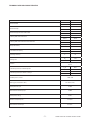 3
3
-
 4
4
-
 5
5
-
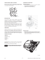 6
6
-
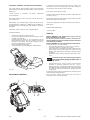 7
7
-
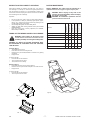 8
8
-
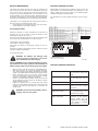 9
9
-
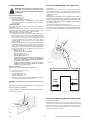 10
10
-
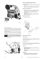 11
11
-
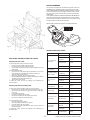 12
12
-
 13
13
-
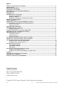 14
14
-
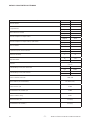 15
15
-
 16
16
-
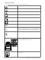 17
17
-
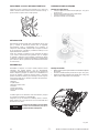 18
18
-
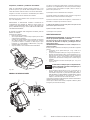 19
19
-
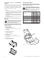 20
20
-
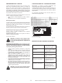 21
21
-
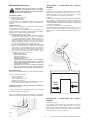 22
22
-
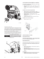 23
23
-
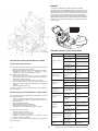 24
24
-
 25
25
-
 26
26
-
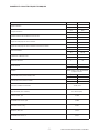 27
27
-
 28
28
-
 29
29
-
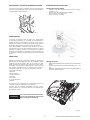 30
30
-
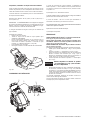 31
31
-
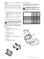 32
32
-
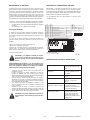 33
33
-
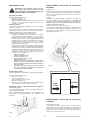 34
34
-
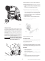 35
35
-
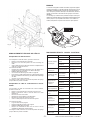 36
36
-
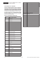 37
37
-
 38
38


Nobles Scout 7 Instrucciones de operación
- Tipo
- Instrucciones de operación
en otros idiomas
- français: Nobles Scout 7 Mode d'emploi
- English: Nobles Scout 7 Operating instructions
Artículos relacionados
Otros documentos
-
Tennant 1264255 Instrucciones de operación
-
Minuteman ROS 17 ORB 115V Manual de usuario
-
Philips RI9355/01 Manual de usuario
-
Vacmaster VJF912PF Manual de usuario
-
Beta 1898/K40 Instrucciones de operación
-
Toro 18in Straight-Shaft Gas Trimmer Manual de usuario
-
GE PSHS6YGZSS El manual del propietario
-
GE Appliances XPIO13BCBT El manual del propietario
-
Zanussi ZHC4284X Manual de usuario
-
 Ferve DUAL F-908 Manual de usuario
