
INSTALLATION / PRODUCT ORIENTATION
Ax B501AP to a suitably at wall. Terminate the cable to the
appropriate terminals. For surface mount wiring the cable can enter
the B501AP via the break outs provided. Select the appropriate Light
Coverage,Tone and Volume settings via the DIP switch.
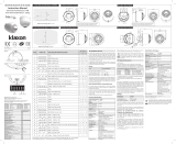
The B501AP incorporates a continuity spring
between terminals 2 and 4. This allows the
continuity of the eld wiring to be checked
without the need for the device to be present.
Inserting the device will disengage the spring.
Removing the device will close the loop.
MODELS
WRA-xC-I02 = Sounder Strobe Isolation Red Flash
WWA-xC-I02 = Sounder Strobe Isolation White Flash
Adjustable performance
Wall Mounted Sounder Strobe
x = Denotes body colour (P - Pure White, R - Red)
GENERAL
(ENG)The range is used in analogue addressable re alarm systems.
These devices must only be connected to control panels that use a compatible
proprietary analogue addressable communication protocol.
These devices receive their power from the loop, and can be controlled via the
communication protocol(s).
Note: if the control equipment is not capable of taking over 99 module
addresses, a fault condition will be generated for every address over 99.
For isolator specication refer to document S00-7400 available on request.
(FRE) La plage est utilisée dans les systèmes analogiques d’alarme incendie
adressables. Ces dispositifs ne doivent être connectés qu’à des panneaux de
commande qui utilisent un protocole de communication adressable analogique
exclusif compatible.
Ces appareils sont alimentés par la boucle et peuvent être contrôlés au
moyens du / des protocole(s) de communication.
Remarque : si l’équipement de commande n’est pas capable d’accepter
plus de 99 adresses de modules, une situation de défaut sera générée pour
chaque adresse au-dessus de 99. Pour les spécications de l’isolateur,
reportez-vous au document S00-7400 disponible sur demande.
(GER) Diese Produktgruppe wird in analogen adressierbaren
Feueralarmsystemen verwendet.
Diese Geräte dürfen nur mit Steuertafeln verbunden werden, die ein
kompatibles proprietäres analoges adressierbares Kommunikationsprotokoll
verwenden.
Die Geräte beziehen ihre Energie aus der Schleife. Sie können über das
Kommunikationsprotokoll kontrolliert werden.
Hinweis: Ist das Steuergerät nicht in der Lage, mehr als 99 Moduladressen
zu verarbeiten, wird bei jeder Adresse, die diese 99 überschreitet, ein
Fehlerzustand erstellt.
Für Isolatorspezikationen siehe Dokument S00-7400, das auf Anfrage
erhältlich ist.
(ITA) La gamma è utilizzata in sistemi antincendio analogici e indirizzabili.
Questi dispositivi devono essere collegati unicamente a pannelli di controllo
compatibili.
Questi dispositivi ricevono la loro alimentazione dal loop e possono essere
controllati tramite il/i protocollo/i di comunicazione.
Nota: se l’apparecchiatura di controllo non riesce a gestire oltre 99 indirizzi del
modulo, si genererà una condizione di guasto per ogni indirizzo successivo al
99.
Per le speciche dell’isolatore fare riferimento al documento S00-7400
disponibile su richiesta.
(SPA) El alcance se utiliza en sistemas direccionables analógicos de alarma
de incendios.
Estos dispositivos solo deben conectarse a paneles de control que utilicen un
protocolo de comunicación direccionable analógico compatible y propio.
Estos dispositivos reciben su energía del lazo y pueden controlarse a través
de los protocolos de comunicación.
Nota: Si el equipo de control no es capaz de tomar más de 99 direcciones de
módulo, se generará un fallo por cada dirección que supere a la dirección 99.
Para conocer las especicaciones del aislante, consulte el documento S00-
7400, disponible previa solicitud.
INSTALLATION INSTRUCTIONS FOR EN54-23 W CLASS WALL MOUNTED LOOP POWERED
ADDRESSABLE SOUNDER STROBES.
(isolation) 15 to 29VDC
(24VDC typical)
(ash rate) 0.5 &1Hz
(standby mode)
130uA
-10°C to +55°C
EN54-3 (sound output)
(High Volume Tone 8 @24V) 96dB(A) ± 3dB
up to 96% (± 3%)
non condensing
2.5mm2
maximum IP rating IP 21C
oC
(max)
P
%
zzz
(max) @24V)
I
V
(operating
temperature)
(humidity)
(terminal size)
High Output
Standard Output
Legacy Output
25.2mA
21.2mA
16.2mA
High Output
Standard Output
Legacy Output
605mW
509mW
389mW
1
2
3
4
+
_
+
_
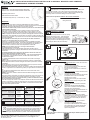
TERMINAL CONNECTIONS
For a full video on how to release the anti-tamper feature please scan
the QR code:
ANTI TAMPER RELEASE
(ENG) IMPORTANT: Follow the instruction
strictly:
1) Insert a at screwdriver
2) Lever the screwdriver down and twist
the device anticlockwise.
3) Remove the screwdriver to unlock the
device.
(FRE) IMPORTANT: Suivez strictement les
instructions :
1) Insérez un tournevis plat
2) Faites descendre le tournevis et tournez
le dispositif dans le sens inverse des
aiguilles d’une montre.
3) Retirez le tournevis pour déverrouiller
l’appareil.
(GER) WICHTIG: Folgen Sie genau den
Anweisungen:
1) Führen Sie einen achen Schrauben-
dreher ein.
2) Drücken Sie den Schraubendreher
nach unten und drehen Sie den Melder
entgegen dem Uhrzeigersinn.
3) Entfernen Sie den Schraubendreher um
den Melder zu entfernen.
(ITA) IMPORTANTE: Seguire interamente
le istruzioni:
1) Inserire un cacciavite a punta piatta
2) Fare leva con il cacciavite verso il basso
e ruotare il dispositivo in verso antiorario
3) Rimuovere il cacciavite per liberare il
dispositivo
(SPA) IMPORTANTE: Siga las instruc-
ciones estrictamente:
1) Inserte un destornillador plano
2) Coloque el destornillador hacia abajo y
gire el dispositivo en sentido antihorario.
3) Retire el destornillador para desblo-
quear el dispositivo.
Make sure the product is tted in the correct orientation!
Scan the barcode below to see the correct
tting to the wall:
CONTINUITY SPRING
This symbol on our product shows a crossed-out “wheelie-bin” as
required by law regarding the Waste of Electrical and Electronic
Equipment (WEEE) disposal. This indicates your responsibility to
contribute in saving the environment by proper disposal of this
Waste i.e. Do not dispose of this product with your other wastes.
To know the right disposal mechanism please check the applicable law.
KAC ALARM COMPANY LIMITED, Honeywell House, Skimped Hill Lane,
Bracknell, Berks, RG12 1EB. T. 02034091779 E. [email protected]
W. www.kac.co.uk

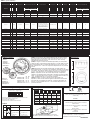
Table 2
DIP setting Pattern Nominal Frequency Switching Frequency Description Market Standard 2nd Stage Tone
Paramètre DIP No Type Fréquence nominale Fréquence de commutation Description Marché Standard
Tonalité de 2ème
niveau
DIP-Schaltereinstellung Muster Nennfrequenz Frequenzwechsel Beschreibung Markt Standard Ton der zweiten Stufe
Impostazione DIP Schema Frequenza nominale Frequenza di commutazione Descrizione Mercato Norma Tono di seconda fase
Configuración DIP Patrón Frecuencia nominal Frecuencia de conmutación Descripción Mercado Norma Tono de 2.ª fase
SW 1,2,3,4,5
O=Off/1=On
Volume - HIGH
(24V/15V)
Volume - NORM
(24V/15V)
Volume - HIGH Volume - NORM
0,0,0,0,0 1 Alternating 525/440 9 / 15.4 4.7 / 8.1 2Hz (100ms/400ms)
French Fire Sound
AFNOR
France NFS 32-001 799 98
1,0,0,0,0 2 Alternating 800/922 8.5 / 14.7 4.9 / 8.5 1Hz UK BS5839 Pt1 898 95
0,1,0,0,0 3 Alternating 800/922 8.4 / 14.7 4.9 / 8.4 2Hz Alternating tone telecoms UK
BS5839 Pt1,
FP1063.1
897 94
1,1,0,0,0 4 Alternating 2400/2900 9.9 / 17.7 5.8 / 10.3 3Hz
Alternating High
Frequency
10 99 95
0,0,1,0,0 5 Alternating 2500/3100 10.2 / 18.3 4.3 / 7.5 2Hz Security Alarm 10 98 90
1,0,1,0,0 6 Alternating 988/645 10 / 17.8 6 / 10.5 2Hz 8100 97
0,1,1,0,0 7 Continuous 630 8.6 / 15 3.1 / 5.3 All clear Sweden 198 94
1,1,1,0,0 8 Continuous 922 9.1 / 15.3 4.8 / 8.3 BS 5839 Pt 1 296 93
0,0,0,1,0 9 Continuous 1200 9.3 / 16.3 4.6 / 7.6 292 90
1,0,0,1,0 10 Continuous 2810 9 / 15 5 / 8.9 HF Continuous 497 93
0,1,0,1,0 11 Sweep 150-1000 9.7 / 17.2 7 / 12.6
Rising from 150Hz to 1000Hz in 10
seconds, then 40 seconds at
1000Hz, then falling from 1000Hz to
150Hz in 10 seconds, then 20
seconds at 150Hz, then repeating.
Total period 80 seconds.
“Gasalarm” Tone 22 100 98
1,1,0,1,0 12 Intermittent 420 8.8 / 15.4 5.1 / 8.6 0.625s on, 0.625 sec off AS2220 alert tone NZ, Aus AS2220 13 100 98
0,0,1,1,0 13 Sweep 500-1200 9 / 15.7 4.9 / 8.6 0.25 sec off, 3.75 sec on AS2220 evacuate tone NZ, Aus AS2220 12 101 99
1,0,1,1,0 14 Intermittent 630 8.4 / 14.7 3.1 / 5.3 3.33Hz 150ms on, 150ms off Swedish alarm tone Sweden 797 93
0,1,1,1,0 15 Intermittent 922 8.9 / 15.4 4.8 / 8.5 0.8Hz 0.25s on, 1s off Intermittent Tone UK BS 5839 Pt 1 895 91
1,1,1,1,0 16 Intermittent 922 8.9 / 15.5 4.8 / 8.5 0.5Hz 1s on, 1s off
Back up alarm LF &
BS5839 Pt 1
UK BS5839 Pt 1 896 90
0,0,0,0,1 17 Intermittent 2810 9.2 / 16.3 5.2 / 9.3 1Hz
Back up alarm HF &
BS5839 Pt 1 2nd tone
UK BS5839 Pt 1 10 98 95
1,0,0,0,1 18 Intermittent 922 8.9 / 15.3 4.8 / 8.5 1Hz 500ms on, 500ms off LF BS5839 Pt 1 UK BS5839 Pt 1 895 92
0,1,0,0,1 19 Intermittent 950 10 / 17.8 5.5 / 9.8
0.22Hz (0.5s on, 0.5s off) rptx3, 1.5s
off
Australia ISO8201 12 99 96
1,1,0,0,1 20 Continuous 800 7.9 / 13.8 3.1 / 5.3 BS 5839 Pt 1 22 98 94
0,0,1,0,1 21 Sweep 400-1200 8.8 / 15.8 4.7 / 8.2 (0.5s on, 0.5s off)*3, 1.5s off
Temporal 3 Evacuation
tone
Australia
ISO8201 Temporal
3
12 99 96
1,0,1,0,1 22 Sweep 1200 - 500 8.5 / 14.8 4.7 / 8.1 0.99Hz 1s on, 0.01s off
Evacuate, DIN tone &
PFEER
Germany DIN, PFEER 20 100 98
0,1,1,0,1 23 Sweep 2400 - 2850 7.4 / 13.1 3.5 / 6 7Hz Fast sweep VdS Germany VdS 10 96 90
1,1,1,0,1 24 Sweep 500 - 1200 8.8 / 17.1 4.9 / 9.6 (0.5s off, 3.5s on)
Slow whoop evacuate
Netherlands
Netherlands NEN 2575 8
98 96
0,0,0,1,1 25 Sweep 800 - 970 8.1 / 14.1 5.3 / 9.6 50Hz LF Buzz BS5839 Pt 1 UK BS5839 Pt 1 8100 98
1,0,0,1,1 26 Sweep 800 - 970 7.6 / 13.2 3.3 / 5.6 7Hz
Fast sweep LF BS5839 Pt
1
UK BS5839 Pt 1 8100 95
0,1,0,1,1 27 Sweep 800 - 970 8.3 / 14.2 3.5 / 6 1Hz
Medium sweep LF,
BS5839 Pt 1, VdS
UK, Germany BS5839 Pt 1 VdS 8101 97
1,1,0,1,1 28 Sweep 2400 – 2850 6.5 / 11.5 3.3 / 5.7 50Hz High frequency buzz 10 96 90
0,0,1,1,1 29 Sweep 500 – 1000 8.9 / 15.6 3.6 / 5.8 7Hz Fast whoop 8100 96
1,0,1,1,1 30 Sweep 500 – 1200 – 500 9.5 / 16.5 4.7 / 8.4 0.166Hz rise 1s, stable 4s, fall 1s Siren style tone 8 99 97
0,1,1,1,1 31 Sweep 800 – 1000 10 / 17.6 5.8 / 10.3 2Hz 8101 99
1,1,1,1,1 32 Sweep 2400 - 2850 8.6 / 15.8 3.8 / 6.6 1Hz 10 97 91
Max consumption (mA, RMS)
Consommation max. (mA, RMS)
Maximalverbrauch (mA, RMS)
Consumo medio (mA, RMS)
Consumo máximo (mA, RMS)
Typical Sound Output (dB)
Sortie sonore type (dB)
Typische Tonausgabe (dB)
Uscita audio tipica (dB)
Salida de sonido típico (dB)
Table 1 (Tone selection)
2831 23
DOP050
W*A-*C-I02
EN 54-3:2001 +A1: 2002 + A2:2006
Fire detection and re alarm systems - Sounders
EN54-23:2010
Fire detection and re alarm systems - Short-circuit
isolators.
Fire detection and re alarm systems - Visual Alarm
Devices
EN 54-17:2005
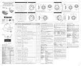
(ENG)To set one of the 159 available addresses for the device use the
two rotay switches located either side of the dip switch unit. The `tens`
digits goes from 0 to 15 and the `units` from 0 to 9. *100 - 159 Only
available with advanced protocol.
(FRE)Pour régler l’une des 159 adresses disponibles pour le dispositif,
utilisez les deux commutateurs rotatifs situés sur l’un des côtés de l’unité
de commutateurs DIP. Les chires des dizaines vont de 0 à 15 et ceux
des unités de 0 à 9. *100 à 159 Uniquement disponible avec le protocole
avancé.
(GER)Verwenden Sie die beiden Drehschalter zu beiden Seiten der
DIP-Schaltereinheit, um eine der 159 verfügbaren Adressen für das Gerät
einzustellen. Die „Zehner“-Ziern reichen von 0 bis 15 und die „Einer“ von
0 bis 9. *100–159 stehen nur mit erweiterten Protokoll zur Verfügung.
(ITA)Per impostare uno dei 159 indirizzi disponibili per il dispositivo
utilizzare i due selettori rotanti posizionati su entrambi i lati dell’unità DIP
switch. Le cifre delle decine vanno da 0 a 15 e quelle delle unità da 0 a 9.
*100 - 159 Disponibili solo con il protocollo avanzato.
(SPA)Para denir una de las 159 direcciones disponibles en el
dispositivo, utilice los dos selectores giratorios situados a ambos lados
del cuadro de conmutadores de selección. Los dígitos decimales van
del 0 al 15 y las unidades del 0 al 9. * 100-159 Solo disponible con el
protocolo avanzado.
Switch 1
Contact 1
Schalter 1
Interruttore 1
Interruptor 1
Switch 2
Contact 2
Schalter 2
Interruttore 2
Interruptor 2
S1 S2
Address 108 = 10 8
Adresse 108 = 10 8
Adresse 108 = 10 8
Indirizzo 108 = 10 8
Dirección 108 = 10 8
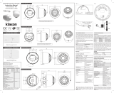
DIP setting 0=Off/1=On. Paramètre DIP 0=Désactivé/1=Activé
DIP-Schaltereinstellung O=Aus/1=Ein.
Impostazione DIP 0=Off/1=On
Configuración DIP 0=Desactivado/1=Activado
1 2 3 4 5 6 7 8
(Refer to table 1 ) (Refer to table 2 )
Address settings
Volume, coverage and frequency settings
ON 1
0
Coverage data
Notifier by Honeywell,
Pittway Tecnologica Srl, Via Caboto 19/3, 34147
Trieste, Italy
0832 23
I56-5005-000
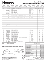
85mm
Dimensions
For LPCB: approved to EN 54-3: 2014 + A1: 2019.
Sounder Output data, in accordance with EN54-3,
is available on Document Ref: S00-7005
121mm
X
Y
Y
For the `O` class detailed coverage data, in accordance
with EN54-23, please request the following doc.: S00-7006
V X (Max) Y (Max) V (m ³)
W-4.2-11.5
W-2.4-11.5
RED
15-29V 4.2m
2.4m
11.5m
11.5m
555
317
W-3.6-10.5
W-2.4-10.5
RED
15-29V 3.6m
2.4m
10.5m
10.5m
397
265
O - 2.4 - 3 RED
15-29V 2.4 3m 21.6
W- 4 -11.5
W-
2.4-11.5
WHITE
15-29V 4m
2.4m
11.5m
11.5m
529
317
W-3.8-9
W-2.4-9 WHITE
15-29V 3.8m
2.4m
9m
9m
308
194
O - 2.4 - 3 WHITE
15-29V 2.4 3m 21.6
Led
EN 54-23
ON OFF
SW6 LOW VOLUME HIGH VOLUME
SW7
0.5Hz
Red
(W-2.4-/W-3.-)
White
(W-2.4-9/W--)
0.5Hz
Red
(W-2.4-1/W-4.-11)
White
(W-2.4-11/:--11)
SW8 f1Hz (O-2.4-3) 0.5Hz (EN54-23 W Class)
-
 1
1
-
 2
2


en otros idiomas
- français: Notifier WRA-xC-I02 Manuel utilisateur
- italiano: Notifier WRA-xC-I02 Manuale utente
- English: Notifier WRA-xC-I02 User manual
Otros documentos
-
 Klaxon 18-980664 Manual de usuario
-
 Klaxon Smoke Alarm 105 DC Manual de usuario
-
 Klaxon Sonos Pulse Sounder Beacon Wall Instrucciones de operación
-
 Klaxon Sonos Pulse Sounder Beacon Ceiling Instrucciones de operación
-
Sonos EN54-23 Manual de usuario
-
McQuay Smoke Alarm 110 AC Manual de usuario
-
 Klaxon Sonos Pulse Beacon Ceiling Instrucciones de operación
-
 Klaxon Sonos Sounder Instrucciones de operación
-
 E2S A105N APPELLO Guía de instalación
-
Optimus A-265VAM Ficha de datos


