Klaxon Sonos Sounder Instrucciones de operación
- Tipo
- Instrucciones de operación

Sonos DC Sounder
Installation Instructions
Issue 21 (Nov 2016) INS533-21
Copyright © Texecom Ltd.
[email protected] www.klaxonsignals.com
Texecom Ltd (Incorporating Klaxon Signals)
St Crispin Way, Haslingden, BB4 4PW, UK.
Tel: +44 1706 233879
EN DE FR NL ES PT IT PL SE DK
0832
16
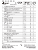
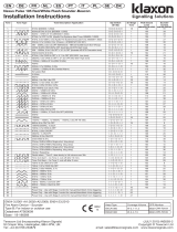
Technical Data Doc.18-186213 Fire Alarm Device - Sounder
Type A: For indoor use (Shallow Base) Type B: For outdoor use (Deep Base)
Fig. 1b
Fig. 1a
Declared Performance
Essential Characteristics EN54-3:2001+A1:2002
A2:2006 Subclause TYPE A TYPE B
Reproducibility 5.2 PASS PASS
Operational performance 5.3 PASS PASS
Durability 5.4 PASS PASS
Dry Heat (operational) 5.5 PASS PASS
Dry Heat (endurance) 5.6 PASS PASS
Cold (operational) 5.7 PASS PASS
Damp heat, cyclic (operational) 5.8 PASS PASS
Damp heat, steady state (endurance) 5.9 PASS PASS
Damp Heat, cyclic (endurance) 5.10 N/A PASS
SO2 corrosion (endurance) 5.11 PASS PASS
Shock (operational) 5.12 PASS PASS
Impact (operational) 5.13 PASS PASS
Vibration (operational) 5.14 PASS PASS
Vibration (endurance) 5.15 PASS PASS
Electrostatic discharge (operational) 5.16 PASS PASS
Radiated electromagnetic elds
(operational) 5.16 PASS PASS
Voltage transients, fast transient
bursts (operational) 5.16 PASS PASS
Enclosure Protection 5.17 PASS PASS
Type CPR Reference
PSS-0084 Reference 0832-CPR-F1923
PSS-0089 Reference 0832-CPR-F1923
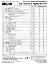
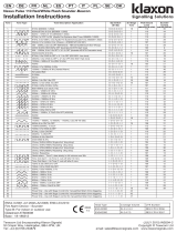
TONE TONE TYPE TONE DESCRIPTION/ APPLICATION DIP SWITCH
1-2-3-4-5 2nd dBA @ 1m mA
1. 970Hz O-O-O-O-O 18 99 17
2. 800Hz/970Hz @ 2Hz O-O-O-O-I 1 100 16
3. 800Hz – 970Hz @ 1Hz O-O-O-I-O 1 100 16
4. 970Hz 1s OFF/1s ON O-O-O-I-I 1 99 10
5. 970Hz, 0.5s/ 630Hz, 0.5s O-O-I-O-O 4 99 15
6. 554Hz, 0.1s/ 440Hz, 0.4s (AFNOR NF S 32 001 ) O-O-I-O-I 1 97 9
7. 500 – 1200Hz, 3.5s/ 0.5s OFF (NEN 2575:2000 Dutch Slow Whoop) O-O-I-I-O 1 99 12
8. 420Hz 0.6s ON/0.6s OFF (Australia AS1670 Alert tone) O-O-I-I-I 9 96 5
9. 1000 - 2500Hz, 0.5s/ 0.5s OFF x 3/1.5s OFF ( AS1670 Evacuation) O-I-O-O-O 1 104 10
10. 550Hz/440Hz @ 0.5Hz O-I-O-O-I 19 97 10
11. 970Hz, 0.5s ON/0.5s OFF x 3/ 1.5s OFF (ISO 8201 ) O-I-O-I-O 1 98 8
12. 2850Hz, 0.5s ON/0.5s OFF x 3/1.5s OFF (ISO 8201) O-I-O-I-I 1 94 17
13. 1200Hz – 500Hz @ 1Hz (DIN 33 404) O-I-I-O-O 1 99 13
14. 400Hz O-I-I-O-I 18 95 9
15. 550Hz, 0.7s/1000Hz, 0.33s O-I-I-I-O 1 98 13
16. 1500Hz – 2700Hz @ 3Hz O-I-I-I-I 1 104 30
17. 750Hz I-O-O-O-O 1 99 14
18. 2400Hz I-O-O-O-I 1 106 41
19. 660Hz I-O-O-I-O 18 96 13
20. 660Hz 1.8s ON/1.8s OFF I-O-O-I-I 19 96 8
21. 660Hz 0.15s ON/0.15s OFF I-O-I-O-O 19 96 7
22. 510Hz, 0.25s/ 610Hz, 0.25s I-O-I-O-I 1 98 11
23. 800/1000Hz 0.5s each (1Hz) I-O-I-I-O 1 100 17
24. 250Hz – 1200Hz @ 12Hz I-O-I-I-I 1 98 9
25. 500Hz – 1200Hz @ 0.33Hz I-I-O-O-O 1 99 14
26. 2400Hz – 2900Hz @ 9Hz I-I-O-O-I 18 101 36
27. 2400Hz – 2900Hz @ 3Hz I-I-O-I-O 18 104 36
28. 500 - 1200Hz, 0.5s/ 0.5s OFF x 3/1.5s OFF ( AS1670 Evacuation) I-I-O-I-I 8 98 6
29. 800Hz – 970Hz @ 9Hz I-I-I-O-O 1 99 16
30. 800Hz – 970Hz @ 3Hz I-I-I-O-I 1 100 6
31. 800Hz, 0.25s ON/1s OFF I-I-I-I-O 1 99 4
32. 500Hz – 1200Hz, 3.75s/0.25s OFF (AS2220) I-I-I-I-I 8 99 13

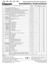
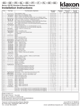
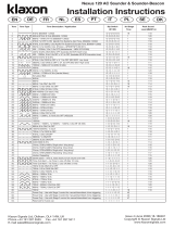
Sonos Basic Wiring Diagrams
1. 9-60V DC Sounder-Only
( 1 ) ( 4 )
( 3 )
( 2 )
-OUT+
IN+
/
( 1 ) ( 4 )
( 3 )
( 2 )
-OUT+
IN+
/
( 1 ) ( 4 )
( 3 )
( 2 )
-OUT+
IN+
/
2nd Stage
From Controller To Next Sounder
or EOL Device
2. 17-60V DC Sounder-Beacon
( 1 ) ( 4 )
( 3 )
( 2 )
-OUT+
IN+
/
( 1 ) ( 4 )
( 3 )
( 2 )
-OUT+
IN+
/
( 1 ) ( 4 )
( 3 )
( 2 )
-OUT+
IN+
/
+
-
Beacon
From Controller To Next Sounder
or EOL Device
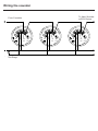
Wiring the sounder
From Controller
2nd Stage
To Next Sounder
or EOL Device

Installation Manual
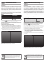
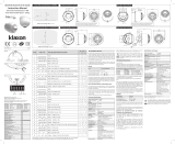
Installation
If required, the mechanism for locking the sounder to the base
can be activated by removing the thin section of plastic shown
in Fig. 1a with side cutters or a similar tool. To open a locked
head, remove the small rubber bung from the hole on the side
of the sounder, insert a tool into the hole and depress the clip
whilst twisting the head. The O-ring and bung must be re-fitted to
maintain the weatherproofing.
An alternative locking method is shown in Fig. 1b. Drive the
hexagonal locking screw forward by turning a 1.5mm hexagonal
key clockwise until the head is locked.
Wiring
Line Terminal Marking
Positive Supply (9 to 60V DC) (3) IN+
Negative Supply (OV) (2) - or COM -
2nd Stage Alarm Control (if required) (1)
The second stage alarm (‘remote tone switching’) is activated by
connecting terminal to Negative (OV) Supply.
A separate earth terminal is provided on the deep base for connecting
the screen or functional earth. On the shallow base, terminal 5 can
be used for this purpose.
Tone Selection and Volume Control
a) The tone is selected using the 5 way dipswitch on the bottom of
the sounder head. Refer to the table overleaf for details of the
available tones and the switch settings required to select them.
b) The sound output of the unit can be reduced by adjusting the
potentiometer on the bottom of the sounder.
Technical Specification
Supply Voltage 9 - 60V DC
Current 4- 41mA*
Peak Sound Level 94 - 106 dBA at 1m*
Number of tones 32
Frequency Range 400 - 2850 Hz*
Rating Continuous
Operating Temperature - 25˚C to + 70˚C
Casing High Impact Polycarbonate
IP Rating IP21/IP65 (deep base)
Syncronisation Automatic
*depends on selected tone and input voltage. See tone table for details.
EN54-3 certified on tones 1,2,3,6,7 & 13 & > 17v DC only.
Installationsanweisung
Installation
Um den Signalgeber im Sockel zu arretieren, ist das
Sicherungsplättchen im Gehäuse zu entfernen. Dies kann
vorsichtig mit einem Seitenschneider oder ähnlichem Werkzeug,
wie in der Abb. 1a dargestellt, herausgelöst werden. Um einen
arretierten Signalgeberkopf aus dem Sockel zu entnehmen, ist
zunächst die weiße Schutzkappe am Kopf herauszuziehen und
durch die Öffnung, mit einem schmalen Schraubendreher, den
innen liegenden Verschlussbügel aus der Arretierungsposition zu
drücken. Um die Schutzklasse zu erhalten, ist die Schutzkappe und
der O-Ring wieder einzusetzen.
Abb. 1b zeigt eine alternative Verriegelungsmethode. Ziehen Sie
die Innensechskant-Feststellschraube durch Drehen eines 1.5 mm
Sechskantschlüssels im Uhrzeigersinn fest.
Verdrahtung
Anschluss Klemme
Common Versorgung + (9 bis 60 V DC) (3) IN+
Versorgung – (0 V) (2) - oder COM -
2.Stufe der Alarmkontrolle (sofern erforderlich) (1)
Die OV-Ausgänge der Schallgeber und Blitzleuchte können zur
gleichzeitigen Steuerung von Ton und Licht über eine 2-adrige
Verbindung miteinander verknüpft werden.
Eine zusätzliche Klemme steht im PG-Sockel zur Verfügung, um
PE oder die Abschirmung auflegen zu können. Im flachen
Montagesockel kann Klemme 5 zu diesem Zweck genutzt werden.
Tonauswahl und Regulierung der Lautstärke
a) Der Ton ist über den 5fach-DIP-Schalter, der sich am Gehäuse
boden befindet, zu selektieren. Die zur Verfügung stehende
Töne und die entsprechenden Schalterkombinationen, sind auf
der Folgeseite gelistet.
b) Die Lautstärke läßt sich über das Potentiometer am Gehäuseboden
einstellen.
Technische Spezifikationen
Betriebsspannung 9 - 60V DC
Stromaufnahme 4- 41mA*
Max. Lautstärkepegel 94 - 106 dBA at 1m*
Anzahl Töne 32
Frequenzbereich 400 - 2850 Hz*
Bemessungsgrundlage Dauerton
Betriebstemperatur - 25˚C to + 70˚C
Gehäuse Schlagbeständiges Polykarbonat
Schutzklasse IP21/IP65 (mit tiefem Sockel)
Syncronisation Automatisch
*je nach gewähltem Ton und Eingangsspannung. Ausführliche Informationen siehe
Tontabelle. EN54-3 zertifiziert nur für Töne 1,2,3,6,7 und 13 und > 17v DC nur.
EN DE
The European directive “Waste Electrical and Electronic Equipment” (WEEE)
aims to minimise the impact of electrical and electronic equipment waste on
the environment and human health. To conform with this directive, electrical
equipment marked with this symbol must not be disposed of in European
public disposal systems. European users of electrical equipment must now
return end-of-life equipment for disposal. Further information can be found on
the following website: http://www.recyclethis.info/.
Das Ziel der EG-Richtlinie über Elektro- und Elektronik-Altgeräte ist, Umwelt-
und Gesundheitsschäden durch Elektro- und Elektronik-Altgeräte so gering wie
möglich zu halten. Um diese Richtlinie einzuhalten, dürfen Elektrogeräte, die mit
diesem Symbol gekennzeichnet sind, nicht in den öffentlichen europäischen
Entsorgungssystemen entsorgt werden. Europäische Benutzer von Elektrogeräten
müssen ab sofort Altgeräte zur Entsorgung zurückgeben. Nähere Informationen
hierzu finden Sie auf der folgenden Website: http://www.recyclethis.info/.

Notice d’instructions
Certification NF
Seules les modèles avec une des références commerciales
suivantes sur leur tête et ayant l’estampille NF sont certifiées NF:
(NF-Système de sécurité incendie - www.marque-nf.com)
Conditions spéciales pour une utilisation avec un système NF-SSI:
1. Certification NF pour le son 6 seulement (AFNOR NF S32-001)
2. Contrôle du volume non disponible
3. La tête doit être verrouillée à la base comme indiqué dans Fig1
Installation
Pour activer le verrouillage de la sirène à sa base, il faut enlever la
fine plaque de plastique comme indiqué sur le dessin 1a avec un
cutter. Pour déverrouiller la base, enlever l’insert blanc situé sur
le côté, insérer un outil dans le trou pour appuyer sur le verrou
tout en faisant pivoter la sirène. Le joint torique et l’insert doivent
être replacé pour maintenir l’étanchéité.
Une autre méthode de blocage est indiquée à la gure 1b. Enler
la vis de blocage hexagonale en utilisant une clé hexagonale de
1.5 mm, et en la faisant tourner dans le sens des aiguilles d’une
montre jusqu’à ce que la tête soit bloquée.
Câblage
Alimentation Bornier
+ Alimentation 9 à 60 Vcc (3) IN+
- Alimentation (0 Vcc) (2) - ou COM -
Commande d’alarme de 2ème étape (si requis) (1)
Les deuxième son (contrôle à distance) sont activés par les
connecteurs (1).
Un terminal terre séparé est fourni sur la base profonde pour
connecter le câble ou terre fonctionnelle. Sur la base étroite, le
terminal 5 peut être utilise a cet effet.
Sélection de tonalité et contrôle du volume
a. La sirène est programmée sur le son AFNOR NF S32-001.
D’autres sons peuvent être sélectionnés en utilisant les
microcontacts. Voir le tableau de choix des sons.
b. Un potentiomètre permet de sègler la puissance sonore
(hors version NF).
Spécification technique
Tension admissible 9 à 60 Vcc
Consommation 4 à 41 mA*
Puissance sonore maximum 94 à 106 dB(A) à 1m*
Nombre de sons 32
Gamme de fréquence De 400 à 2850 Hz*
Régime nominal Continu
Température de fonctionnement De - 25°C à + 70°C
Matière Polycarbonate résistant au choc
Degré d’étanchéité IP21/IP65 (avec base longue)
Syncronisation Automatique
* Variable selon les sons et les tensions. Voir tableau des sons pour plus
d’informations. Certifié selon la EN54-3 pour les tons 1, 2, 3, 6, 7 et 13. et >17v DC
seulement.
Montageinstructies
Montage
Indien nodig kan het mechanisme om het alarm aan de basis te
vergrendelen worden geactiveerd door het verwijderen van het
dunne stukje plastic met een tang of vergelijkbaar gereedschap
zoals aangegeven in Fig. 1a. Om een vergrendelde kop te openen:
verwijder de kleine witte stop uit het gat aan de zijkant van het
alarm, steek een schroevendraaier o.i.d. in het gat en druk het
lipje in terwijl u de kop draait. De o-ring en de stop moeten worden
teruggeplaatst om de waterdichtheid te behouden.
In Fig. 1b wordt een alternatieve vergrendelingsmethode getoond.
Draai de zeskantborgschroef met een 1.5 mm zeskantsleutel naar
rechts tot de kop is vergrendeld.
Bedrading
Lijn Contact markerin
Positieve voeding (9 - 60V DC) (3) IN+
Negatieve voeding (OV) (2) - of COM -
2e fase Alarm Control (indien nodig) (1)
Het tweedefase alarm (toonselectie op afstand) wordt geactiveerd
door het aansluiten van het contact aan de negatieve
(OV) voeding.
Op de hoge basis is een aparte aardaansluiting aanwezig voor
het aansluiten van het scherm of de aarde. Op de lage basis kan
uitgang 5 hiervoor gebruikt worden.
Toonkeuze en volumebediening
a) De toon wordt geselecteerd met de vijfweg-instelschakelaar op de
onderkant van de alarmkop. Kijk op de tabel aan ommezijde
voor gegevens over de beschikbare tonen en de schakelaarin
stellingen om deze te selecteren.
b) De geluidsuitvoer van de eenheid kan verminderd worden door
het aanpassen van de potentiometer aan de onderkant van het
alarm.
Technische specificaties:
Spanningsbereik 9 - 60V gelijkstroom
Stroomsterkte 4 - 41mA*
Geluidsniveaupiek 94 - 106 dBA op 1m*
Aantal tonen 32
Frequentiebereik 400 - 2850 Hz*
Belasting Continu
Gebruikstemperatuur - 25˚C tot + 70˚C
Behuizing Slagvast polycarbonaat
IIP waarde IP21/IP65 (ALLEEN met hoge basis)
Synchronisatie Automatisch
*afhankelijk van de gekozen toon en het voltage. Zie de toontabel voor details.
Door de EN54-3 gecertificeerd, alleen tonen 1,2,3,6,7 en 13 en >17v DC alleen.
FR NL
No. identication
NF-SSI
Référence commerciale
(“Head Type”)
Description
DS 010 B1 PSS-0089 Sonos DC Sounder (blanc)
La directive européenne “ Déchets d’Equipements Electriques et Electroniques “
(DEEE) a pour but de minimiser l’impact des déchets électriques et électroniques
sur l’environnement et la santé humaine. Conformément à cette directive, tout
équipement électrique disposant de ce symbole ne doit pas être jeté dans
les systèmes d’évacuation des déchets publics européens. Les utilisateurs
européens d’équipement électrique doivent désormais renvoyer tout équipement
électrique en fin de vie pour évacuation. Vous trouverez de plus amples
informations sur le site Web suivant : http://www.recyclethis.info/.
De Europese richtlijn “Afgedankte elektrische en elektronische apparatuur”
(AEEA) is er op gericht om de impact van het afval van elektrische en elektronische
apparatuur op het milieu en de gezondheid van de mens te minimaliseren. Om
aan deze richtlijn te voldoen, moet elektrische apparatuur die met dit symbool
gemarkeerd is, niet worden verwerkt in Europese openbare afvalsystemen.
Europese gebruikers van elektrische apparatuur dienen nu apparatuur aan het
einde van de levensduur aan te bieden voor verwerking.Meer informatie vindt u
op de volgende website: http://www.recyclethis.info/.

Instrucciones de Instalación
Instalación
Active el mecanismo de seguridad si esto fuera necesario, para
evitar que la sirena pueda ser desconectada de la base. Para
hacer esto, corte el cacho de plástico que le mostramos en la Fig. 1a.
Una sirena que haya sido bloqueada, solo se puede desbloquear
quitando el pequeño tapón situado en el lateral e insertando
una pequeña varilla para presionar el mecanismo de bloqueo.
Debemos asegurar que la arandela y el tapón están colocados
para asegurar la resistencia a intemperie.
La Fig. 1b muestra un método de sujeción alternativo. Mueva
el tornillo de sujeción hexagonal hacia delante girando la llave
hexagonal de 1.5 mm en sentido horario hasta que la cabeza
quede jada.
Cableado
Línea Terminal
Positivo (9-60V DC) (3) IN+
Negativo (0V) (2) - ou COM -
Mando de control de la alarma – 2ª fase
(si fuera necesaria) (1)
La segunda fase de alarma (‘cambio de tono’) se activa
conectando al Negativo (0V).
Selección de Tono y Control de Volumen
a) El tono se selecciona usando el interruptor de 5 posiciones
situado en la parte inferior de la sirena. Mire la tabla adjunta para
ver detalles de los tonos disponibles y las posiciones del interruptor
para seleccionar el tono requerido.
b) El volumen de la sirena se puede ajustar usando el potenciómetro
situado en la parte inferior de la sirena.
Especificaciones Técnicas
Voltaje de Alimentación 9- 60V DC
Consumo 4- 41mA*
Máximo Nivel Sonoro 94 - 106 dBA a 1m*
Número de Tonos 32
Frecuencia 400 - 2850 Hz*
Régimen Continuo
Temperatura de Funcionamiento - 25°C a + 70°C
Carcasa Policarbonato Resistente al Fuego
Clasificación IP IP21/IP65 (Con Base de Entrada
de Tubo)
Sincronización Automática
* depende del tono seleccionado y la tensión de alimentación.
Ver la tabla de tonos para los detalles. EN54-3 accreditado solamente tonos 1,2,3,6,7
& 13 >17v DC sólo.
ES Manual de Instalação
Instalação
Se necessário, o mecanismo para fixar o sensor à base pode
ser activado removendo a fina película de plástico ilustrada na Fig.
1a com um alicate de corte ou uma ferramenta semelhante. Para
abrir uma cabeça bloqueada, retire o pequeno tampão branco do
orifício existente na parte lateral do sensor, insira uma ferramenta
no orifício e carregue na mola enquanto roda a cabeça. O
O-ring e o tampão devem ser reinstalados no intuito de manter a
estanquicidade às intempéries.
Na Fig. 1b é apresentado um método de bloqueio alternativo.
Avance o parafuso de bloqueio hexagonal ao rodar uma chave
hexagonal de 1.5 mm no sentido dos ponteiros do relógio até ao
bloqueio da cabeça.
Cablagem
linha Marcação Terminal
Alimentação positiva (9 to 60V DC) (3) IN+
Alimentação negativa (OV) (2) - or COM -
Controlo de alarme de 2ª fase (se necessário) (1)
O alarme de 2ª fase (“comutação de mensagem sonora remota”) é
activado ligando o terminal à alimentação negativa (OV).
É fornecido um terminal terra independente na base profunda para
ligar o ecrã ou a terra funcional. Na base côncava, pode utilizar-se
o terminal 5 para este fim.
Selecção de mensagens sonoras e controlo do volume
a) A mensagem sonora é seleccionada utilizando o comutador DIP
Switch de 5 vias existente na parte inferior da cabeça do sensor.
Consulte a tabela no verso para obter detalhes sobre as mensagens
sonoras disponíveis e configurações do comutador necessárias
para as seleccionar.
b) É possível reduzir o volume de som da unidade regulando o
potenciómetro existente na parte inferior do sensor.
Especificações técnicas
Gama da tensão de alimentação 9 - 60V DC
Corrent 4 - 41mA*
Nível sonoro de pico 94 - 106 dBA at 1m*
Número de mensagens sonoras 32
Gama de frequência 400 - 2850 Hz*
Regime Permanente
Temperatura de funcionamento - 25˚C a + 70˚C
Caixa Policarbonato de alto impacto
Classe de protecção IP21/IP65 (com base profunda)
Sincronização Automático
*depende do tom seleccionado e da tensão de entrada. Para mais informações, consultar a
tabela de tons. Certificado apenas nos tons 1,2,3,6,7 e 13. >17v DC apenas.
PT
A Directiva europeia “Resíduos de Equipamentos Eléctricos e Electrónicos”
(REEE) tem como objectivo minimizar o impacto dos resíduos de equipamentos
eléctricos e electrónicos no ambiente e na saúde humana. Para dar
cumprimento a esta Directiva, o equipamento eléctrico que contenha este
símbolo não deve ser eliminado nos sistemas de eliminação pública europeus.
Os utilizadores europeus de equipamento eléctrico devem agora devolver os
equipamentos em fim de vida para eliminação. Para mais informações,
consultar o seguinte sítio da Web: http://www.recyclethis.info/.
El objetivo de la directiva europea de Eliminación de equipos eléctricos y electrónicos
(WEEE) es minimizar el impacto de la eliminación de equipos eléctricos y
electrónicos sobre el medioambiente y la salud de las personas. Para cumplir con
esta directiva, el equipamiento eléctrico marcado con este símbolo no deberá
desecharse en ningún sistema de eliminación europeo público. Los usuarios
europeos de equipamiento eléctrico deberán retornar los equipos eléctricos y
electrónicos al final de su vida útil para su eliminación. Para más información
visite el siguiente sitio Web: http://www.recyclethis.info/.

Istruzioni di installazione
Installazione
Se necessario, è possibile attivare il meccanismo di bloccaggio del
segnalatore acustico alla base rimuovendo la sottile linguetta di
plastica illustrata nella Fig. 1a con un tronchesino o un attrezzo
simile. Per aprire una testina bloccata, rimuovere il piccolo
tappo bianco dal foro laterale del segnalatore acustico, inserire
un attrezzo nel foro e premere il fermo svitando la testina. La
guarnizione ad anello e il tappo devono essere riposizionati per
mantenere la resistenza alle intemperie.
La Fig. 1b mostra un metodo di bloccaggio alternativo. Serrare la
vite di bloccaggio esagonale ruotando una chiave esagonale da
1.5 mm no al bloccaggio della testa.
Cablaggio
Linea Contrassegno sui terminali
Alimentazione positiva (9 - 60V DC) (3) IN+
Alimentazione negativa (OV) (2) - of COM -
Controllo allarme 2a fase (se necessario) (1)
L’allarme di seconda fase (“commutazione remota tono”) viene
azionato collegando il terminale all’alimentazione negativa
(OV).
La base profonda è dotata di un terminale di terra separato per il
collegamento dello schermo o della terra funzionale. Sulla base
superficiale, allo stesso scopo è possibile usare il terminale 5.
Selezione toni e Controllo volume
a) Il tono viene selezionato usando un commutatore a 5 vie situato
sulla parte inferiore della testina del segnalatore acustico.
Consultare la tabella a tergo per informazioni sui toni disponibili
e sulle impostazioni del commutatore necessarie per selezionarli.
b) È possibile ridurre l’emissione di suono dell’unità regolando il
potenziometro sulla parte inferiore del segnalatore.
Specifiche tecniche
Gamma tensione di alimentazione 9 - 60V CC
Corrente 4 - 41mA*
Livello di picco del suono 94 - 106 dBA a 1m*
Numero di toni 32
Gamma di frequenza 400 - 2850 Hz*
Prestazione Continua
Temperatura di esercizio - 25˚C to + 70˚C
Alloggiamento Policarbonato ad alto impatto
Classe di IP IP21/IP65 (SOLO con base profonda)
Sincronizzazione Automatica
*dipende dal tono selezionato e dalla tensione di ingresso. Per infor mazioni
dettagliate, consultare la tabella dei toni. Certicazione EN54-3 solo sui toni 1,2,3,6,7
e 13 e >17v DC solo.
IT Instrukcja montażu
Instalacja
W razie potrzeby mechanizm blokujący głośnik na podstawie
można uruchomić, usuwając cienką warstwę folii pokazaną na Rys.
1a za pomocą szczypiec lub podobnego narzędzia. Aby
otworzyć zablokowaną głowicę, należy usunąć małe, białe
zamknięcie z otworu bocznego głośnika i za pomocą narzędzia
umieszczonego w otworze nacisnąć zatrzask jednocześnie
przekręcając głowicę. Pierścień „O” i zamknięcie muszą zostać
założone ponownie, aby zapewnić zabezpieczenie przed
warunkami pogodowymi.
Inną metodę blokowania przedstawiono na rysunku 1b. Obróć
w prawo sześciokątną śrubę blokującą za pomocą klucza
sześciokątnego 1.5 mm aż do zablokowania głowicy.
Okablowanie
Linia Listwa zaciskowa
Normalne zasilanie (9 to 60V DC) (3) IN+
Ujemne zasilanie (OV) (2) lub COM
Sterowanie alarmu 2 etapu (jesli wymagane) (1)
Alarmdrugiego etapu („zdalne przełaczanie tonów”) jest
uruchamiany przez podłaczenie listwy zaciskowej do
zasilania ujemnego (OV).
W głębokiej podstawie dostępna jest oddzielna listwa zaciskowa
dla podłączenia ekranu lub zera roboczego. W przypadku płytkiej
podstawy do tego celu służy zacisk 5.
Wybór tonu i regulacja głośności
a) Ton wybierany jest za pomocą 5 pozycyjnego przełącznika dipswitch
znajdującego się na spodzie głowicy głośnika. W celu uzyskania
informacji dotyczących dostępnych tonów i odpowiadających
im ustawień przełączników, należy zapoznać się z tabelą na
odwrocie.
b) Dźwięk wyjściowy urządzenia można zredukować za pomocą
potencjometru znajdującego się na spodzie głośnika.
Dane techniczne
Zakres napięcia zasilania 9 - 60V DC
Prąd 4 - 41mA*
Szczytowe natężenie dźwięku 94 - 106 dBA at 1m*
Ilość tonów 32
Zakres częstotliwości 400 - 2850 Hz*
Wartosc ciagłej pracy
Temperatura pracy - 25˚C to + 70˚C
Obudowa Wytrzymałego poliwęglanu
Oznaczenie IP IP21/IP65 (z głęboką podstawą)
Synchronizacja Automatyczna
*zależy od wybranego tonu i napięcia wejściowego. W celu uzyskania szczegółowych
informacji należy zapoznać się z informacjami podanymi w tabeli tonów. Gwarantowane
wyłącznie w przypadku tonów 1, 2, 3, 6, 7 i 13 i >17v DC tylko.
PL
La Direttiva europea nota come “Waste Electrical and Electronic Equipment”
(WEEE), è volta a ridurre al minimo l’impatto sull’ambiente e sulla salute umana
provocato dallo smaltimento di apparecchiature elettriche ed elettroniche. Al
fine di garantire conformità a tale direttiva, è vietato smaltire le apparecchiature
elettriche contrassegnate da questo simbolo nei comuni cassonetti per lo
smaltimento dei rifiuti siti in territorio europeo. Gli utilizzatori europei sono tenuti
a restituire le apparecchiature elettriche ed elettroniche al termine del loro ciclo
di vita per consentirne il corretto smaltimento.Per ulteriori informazioni, visitare
il seguente indirizzo: http://www.recyclethis.info/.
Dyrektywa europejska „W sprawie zużytego sprzętu elektrycznego i
elektronicznego” (WEEE) ma na celu zmniejszenie wpływu odpadów sprzętu
elektrycznego i elektronicznego na środowisko i zdrowie człowieka. Aby
spełnić wymagania dyrektywy, sprzęt elektryczny oznaczony tym symbolem
nie może być usuwany razem z odpadami komunalnymi. Obecnie użytkownicy
sprzętu elektrycznego na terenie Europy po zakończeniu użytkowania
sprzętu muszą zwracać go w celu jego utylizacji. Szczegółowe informacje
podano w witrynie internetowej: http://www.recyclethis.info/.

Installationsmanual
Installation
Om så behövs, kan mekanismen för att låsa summern vid basen
aktiveras genom att avlägsna den tunna plastbiten, såsom visas
i Fig. 1a, med en sidavbitare eller liknande. För att öppna ett
låst huvud, avlägsna den lilla vita proppen från hålet på sidan av
summern, för in ett verktyg i hålet och tryck ned klämman medan
huvudet vrids. O-ringen och proppen måste sättas tillbaka för att
bibehålla väderskyddet.
En alternativ låsmetod visas i Fig. 1b. Driv den sexkantiga
låsskruven framåt genom att vrida en 1.5 mm insexnyckel medsols
tills huvudet är låst.
Koppling
Ledning Kabelfäste
Positivt nät (9 to 60V DC) (3) IN+
Nätgativ nät (OV) (2) – eller COM –
Tvåfaslarm (om så behövs) (1)
Tvåfaslarmet (‘fjärrtonsväxling) aktiveras genom att ansluta
klämman till negativt (OV) nät.
En separat jordklämma finns på den djupa basen för att anslutas
till skärmen eller funktionsjord. På den låga basen, kan klämma 5
användas för detta ändamål.
Tonval och volymkontroll
a) Tonen ställs in med en femvägs dipswitch på summerhuvudets
undersida. Se tabellen på nästa sida för uppgifter om tillgängliga
toner och switchinställningar som krävs för att välja dem.
b) Ljudeffekten för enheten kan minskas genom att justera
potentiometern på summerns undersida.
Teknisk specifikation
Matningsspänningsområde 9 - 60V likström
Ström 4 - 41mA*
Toppljudnivå 94 - 106 dBA vid 1m*
Antal toner 32
Frekvensområde 400 - 2850 Hz*
Rating Continuous
Arbetstemperatur - 25˚C to + 70˚C
Hus Hus av extra slagtåligt polykarbonat
IP-värde IP21/IP65 (med djup bas)
Synkronisering Automatisk
*beroende på vald ton och inspänning. Se tontabellerna för uppgifter.
Enbart kalibrerad för toner 1,2,3,6,7 & 13 & >17v DC endast.
Installationsanvisninger
Installation
Om nødvendigt kan mekanismen for aflåsning af lyd alarmen til
underlaget aktiveres ved at fjerne det tynde plastik lag, som vist
på fig. 1a; dette kan gøres med sideskærere eller et lignende
værktøj. For at åbne et låst hoved, fjern den lille hvide spunstap fra
hullet på lyd alarmens side, og sæt et værktøj ind i hullet og tryk
klemmen ned mens hovedet drejes. O-ringen og spunstappen skal
genmonteres for at bevare vejrtætningen.
En alternativ låsemetode er vist i Fig. 1b. Før den sekskantede
låseskrue fremad ved at dreje en 1.5mm sekskantet indstiksnøgle
med uret, indtil hovedet er låst fast.
Trådføring
Ledning Klemme Marking
Positiv strømforsyning (9 bis 60 V DC (3) IN+
Negative strømforsyning (0 V) (2) - elle COM -
2. Niveau alarmkontrol (om nødvendigt) (1)
Anden niveau alarmkontrol (‘fjern tone omstilling’) aktiveres ved
at tilslutte terminalen til den negative (OV) strømforsyning.
Der findes en separat jordklemme på det dybe underlag for
tilslutning af skærmen eller den funktionelle jordklemme. På det
flade underlag, kan klemme 5 bruges til dette formål.
Valg af tone og lydkontrol
a) Tonen vælges med en femvejs nedblænder, som sidder på
bunden af lyd alarmens hoved. Der henvises til tabellen på
næste side for nærmere oplysninger om tilgængelige toner og
hvilke omkoblerindstillinger der skal vælges.
b) Enhedens lydeffekt kan reduceres ved at justere spændingsmåleren
på bunden af lyd alarmen.
Teknisk specifikation
Strømforsyningens
spændingsområde 9 - 60V DC
Strøm 4 – 41 mA
Maksimalt lydniveau 94 - 106 dBA ved 1m*
Antal toner 32
Frekvensområde 400 - 2850 Hz*
Rating Continuous
Driftstemperatur - 25˚C to + 70˚C
Hus Slagfast hus af polykarbonat
IP kapacitet IP21/IP65 (med dybt underlag)
Synkronisering Automatisk
*afhænger af den valgte tone og indgangsspænding. Se tone tabellen for nærmere
oplysninger. Kun certificerede toner 1,2,3,6,7 & 13 & >17v DC kun.
SE DK
Det europeiska direktivet om avfall som utgörs av eller innehåller elektriska
eller elektroniska produkter (WEEE) har i syfte att minimera verkningen av
elektriskt och elektroniskt avfall på miljö och människors hälsa. För att följa detta
direktiv, får elektrisk utrustning märkt med denna symbol inte avfallshanteras
i europeiska kommunala avfallssystem. Europeiska brukare av elektrisk
utrustning måste numera lämna tillbaka uttjänad utrustning för avfallshantering.
Ytterligare information finns på följande hemsida: http://www.recyclethis.info/.
Det europæiske direktiv “Waste Electrical and Electronic Equipment” (WEEE)
satser på at reducere påvirkningen af affald fra elektrisk og elektronisk ud-
styr på miljøet og menneskers sundhed. For at overholde dette direktiv, må
elektrisk udstyr med dette symbol ikke kasseres i offentlige europæiske
affaldssystemer. Europæiske brugere af elektrisk udstyr skal returnere udtjent
udstyr for kassering. Yderligere information findes på følgende webside: http://
www.recyclethis.info/.
-
 1
1
-
 2
2
-
 3
3
-
 4
4
-
 5
5
-
 6
6
-
 7
7


Klaxon Sonos Sounder Instrucciones de operación
- Tipo
- Instrucciones de operación
en otros idiomas
- français: Klaxon Sonos Sounder Mode d'emploi
- italiano: Klaxon Sonos Sounder Istruzioni per l'uso
- Deutsch: Klaxon Sonos Sounder Bedienungsanleitung
- Nederlands: Klaxon Sonos Sounder Handleiding
- português: Klaxon Sonos Sounder Instruções de operação
- dansk: Klaxon Sonos Sounder Betjeningsvejledning
- polski: Klaxon Sonos Sounder Instrukcja obsługi
Artículos relacionados
-
 Klaxon Smoke Alarm 105 DC Manual de usuario
-
 Klaxon 18-980664 Manual de usuario
-
 Klaxon 120 DC Manual de usuario
-
 Klaxon Sonos Pulse Sounder Beacon Wall Instrucciones de operación
-
 Klaxon Sonos Pulse Sounder Beacon Ceiling Instrucciones de operación
-
 Klaxon Nexus Pulse 105 & 110 Instrucciones de operación
-
 Klaxon Nexus Pulse 105 & 110 Instrucciones de operación
-
 Klaxon Nexus 105/110/120 Sounder Instrucciones de operación
-
McQuay Smoke Alarm 110 AC Manual de usuario
-
 Klaxon Nexus 120 AC Manual de usuario


