JVC KS-DR2104DBT Manual de usuario
- Categoría
- Amplificadores de audio para automóviles
- Tipo
- Manual de usuario

B5A-3629-10 / 01 (KN)
© 2021 JVCKENWOOD Corporation
Accessories / Accessoires / Accesorios
Remote control unit
Télécommande
Mando a distancia
1
Ø4×16 mm
Self-tapping screws
Vis taraudeuses
Tornillo autorroscantes
4
Mounting bracket
Support de montage
Ménsula de montaje
1
Ø3×8 mm
Self-tapping screws
Vis taraudeuses
Tornillo autorroscantes
1
Double-side adhesive tape
Ruban adhésif double-face
Cinta adhesiva de doble cara
1
KS-DR2104DBT
COMPACT BLUETOOTH® 4 CHANNEL DIGITAL AMPLIFIER
INSTRUCTION MANUAL
AMPLIFICATEUR BLUETOOTH® COMPACT 4 CANAUX NUMÉRIQUE
MODE D’EMPLOI
AMPLIFICADOR DIGITAL COMPACTO BLUETOOTH® DE 4 CANALES
MANUAL DE INSTRUCCIONES
JVC
JVCKENWOOD Corporation
■
D

Safety
precautions
IAWARNING
I
To
prevent
injury
or
fire,
take
the
following
precautions:
•
Mounting
and
wiring
this
product
requires
skills
and
experience.
For
safety's
sake,
leave
the
mounting
and
wiring
work
to
professionals.
•
To
prevent
a
short
circuit
,
never
put
or
leave
any
metallic
objects
(s
uch
as
coins
or
metal
tools)
inside
the
unit.
•
If
the
unit
starts
to
emit
smoke
or
strange
smells,
turn
off
the
power
immediately
and
consult
your
JVC
dealer.
•
Do
not
touch
the
unit
during
use
because
the
surface
of
the
unit
becomes
hot
and
may
cause
burns
if
touched.
I A CAUTION I
To
prevent
damage
to
the
machine,
take
the
following
precautions:
•
Be
sure
the
unit
is
connected
to
a
12
V
DC
power
supply
with
a
negative
ground
connection.
•
Do
not
open
the
top
or
bottom
covers
of
the
unit.
•
Do
not
install
the
unit
in
a
spot
exposed
to
direct
sunlight
or
excessive
heat
or
humidity.
•
When
replacing
a
fuse
,
only
use
a
new
one
with
the
prescribed
rating.
Using
a
fuse
with
the
wrong
rating
may
cause
your
unit
to
malfunction.
•
To
prevent
a
short
circuit
when
replacing
a
fuse
,
first
disconnect
the
wiring
harness.
I NOTE I
•
If
you
experience
problems
during
installation,
consult
your
JVC
dealer.
•
If
the
unit
does
not
seem
to
be
working
right
,
consult
your
JVC
dealer.
Cleaning
the
unit
If
the
front
panel
gets
dirty,
turn
off
the
power
and
wipe
the
panel
with
a
dry
silicon
cloth
or
soft
cloth.
I A CAUTION I
Do
not
wipe
the
panel
with
a
hard
cloth
or
a
cloth
dampened
by
volatile
solvents
such
as
paint
thinner
and
alcohol.
They
can
scratch
the
surface
of
the
panel
and/
or
cause
the
indicator
letters
to
peel
off.
To
prevent battery rise
When
the
unit
is
used
in
the
ACC
ON
position
without
turning
the
engine
ON
,
it
depletes
the
battery.
Use
it
after
starting
the
engine.
Protection function
The
protection
function
is
activated
in
the
following
situations:
This
unit
is
equipped
with
a
protection
function
for
protecting
this
unit
and
your
speakers
from
various
accidents
or
problems
that
can
occur.
When
the
protection
function
is
triggered
,
the
amplifier
stops
operating.
•
When
a
speaker
wire
may
be
short-circuited.
•
When
a
speaker
output
contacts
ground.
•
When
the
unit
malfunctions
and
a
DC
signal
is
sent
to
the
speaker
output.
•
When
the
internal
temperature
is
high
and
unit
won't
operate
.
•
When
detects
a
low
impedance
at
the
speaker
connections.
Wiring
•
If
a
buzzing
noise
is
heard
from
the
speakers
when
the
engine
is
running,
connect
a
line
noise
filter
(optional)
to
each
of
the
battery
wire.
•
Do
not
allow
the
wire
to
directly
contact
the
edge
of
the
iron
plate
by
using
Grommets.
•
Connect
the
ground
wire
to
a
metal
part
of
the
car
chassis
that
acts
as
an
electrical
ground
passing
electricity
to
the
battery
's
negative8terminal.
Do
not
turn
the
power
on
if
the
ground
wire
is
not
connected.
•
Be
sure
to
install
a
protective
fuse
in
the
power
cord
near
the
battery.
The
protective
fuse
should
be
the
same
capacity
as
the
unit's
fuse
capacity
or
somewhat
larger.
•
When
more
than
one
power
amplifier
are
going
to
be
used
,
use
a
power
supply
wiring
wire
and
protective
fuse
of
greater
current-handling
capac-
ity
than
the
total
maximum
current
drawn
by
each
amplifier.
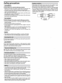
Speaker selection
•
Using
speakers
with
smaller
input
ratings
than
the
amplifier
's
output
power
would
result
in
smoke
generation
or
equipment
failure.
•
The
impedance
of
the
speakers
that
are
going
to
be
connected
should
be
2 0
or
greater
(for
stereo
connections),
or
4 0
or
greater
(for
bridged
connections).
When
more
than
one
set
of
speakers
are
going
to
be
used
,
calculate
the
combined
impedance
of
the
speakers
and
then
connect
suitable
speakers
to
the
amplifier.
<
Example
>
~----
--,
-------------~
0 '
40
:~·:
' ' '
• • '
40
40,
,
e·
,
-
40
' - •
I I I I
'•
• • • • •
•·
'•
- • • • •
•••••••I
so
Combined
20
t_
impedance
__j'

How to reset
Comment réinitialiser
Cómo reinicializar
Press and hold and .
Maintenez enfoncée et
.
Pulse mantenga pulsado
y .
Troubleshooting guide
Sound cannot be heard.
• Check the cords and connections.
• Protection circuit may be activated. Check connections. ( “Protection
function”)
• Blown fuse. Replace the fuse.
• The speaker cord is shorted. After check the speaker cord and xing the
cause of the short, replace the fuse.
The sound quality is bad. (The sound is distorted.)
• Connect the speaker cord properly checking the / of the terminals
and wires well.
• Connect the speaker cord again so that it is not pinched by anything.
No Bluetooth device is detected.
Reset the unit. (
“
How to reset
”
)
Bluetooth pairing cannot be made.
Delete pairing information from both the unit
(
“
How to reset
”
)
and the
Bluetooth device, then perform pairing again.
Sound is being interrupted or skipped during playback of a
Bluetooth audio player.
• Reduce the distance between the remote control unit and the Bluetooth
audio player.
• Other Bluetooth devices might be trying to connect to the unit.
The connected Bluetooth audio player cannot be controlled.
• Check whether the connected Bluetooth audio player supports Audio/
Video Remote Control Pro le (AVRCP). (Refer to the instructions of your
audio player.)
• Disconnect and connect the Bluetooth player again.
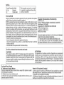
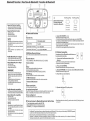
Specifications
Speci cations subject to change without notice.
Audio unit
Max power output ................................................................................600 W
Rated power output (+B = 14.4V)
Stereo (4 Ω) ...................................50 W × 4 (20 Hz–20 kHz, ≤ 1.0 % THD)
Stereo (2 Ω) ................................................75 W × 4 (1 kHz, ≤ 1.0 % THD)
Bridged (4 Ω) ...........................................150 W × 2 (1 kHz, ≤ 1.0 % THD)
Speaker impedance ................................................ 4 Ω (2 Ω to 8 Ω allowable)
(Bridged connection: 4 Ω to 8 Ω allowable)
Frequency response (+0, –3 dB)...............................................10 Hz–20 kHz
Signal to noise ratio ...............................................................................89 dB
Low pass lter frequency (–12 dB/oct.) ................... 50 Hz–200 Hz (variable)
High pass lter frequency (–12 dB/oct.) .................. 50 Hz–200 Hz (variable)
Preout ............................................................................................. 5V (Max.)
Bluetooth
Version ................................................................................ Bluetooth Ver.5.0
Frequency range ..........................................................2,402 GHz–2,480 GHz
RF output power (E.I.R.P.)................................+4 dBm (Max.), Power Class 2
Pro le .........................................A2DP (Advanced Audio Distribution Pro le)
AVRCP (Audio/Video Remote Control Pro le)
General
Operating voltage .............................................................12 V DC car battery
Current consumption ...............................................................................26 A
Operational temperature range................................................. –10˚C – 60˚C
Dimensions (W × H × D) ..............................................198 × 48.5 × 104 mm
7-13/16 × 1-15/16 × 4-1/8 inch
Weight .................................................................................... 1.6 kg (3.5 lbs)
Water-proof & Dust-proof ...............................................................IP66, IP67
50 Watts RMS × 4 at 4 Ohms and ≤ 1% THD+N
74 dBA (Reference: 1 Watt into 4 Ohms)
50 Watts RMS × 4 à 4 Ohms et ≤ 1% THD+N
74 dBA (Référence: 1 Watt dans 4 Ohms)
50 Vatios RMS × 4 a 4 Ohmios y ≤ 1% de distorsión
armónica total+N
74 dBA (Referencia: 1 Vatio en 4 Ohmios)
-
I I
-
I t
-
I
CD
(f) t
I I
t
■■■

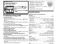
Dimensions / Dimensions / Dimensiones
181 mm (7-1/8”)
200 mm (7-7/8”)
198 mm (7-13/16”)
48.5 mm (1-15/16”)
104 mm (4-1/8”)
88 mm (3-7/16”)
84.0 mm (3-5/16”) 51.0 mm (2”)
45.1 mm
(1-3/4”)
99.0 mm (3-7/8”)
52.8 mm (2-1/16”)
25.8 mm (1”)
27.0 mm (1-1/16”)
58.1 mm
(2-5/16”)
■
- -
~
~
.._
JVC
drun
t---------- ( -
JVC

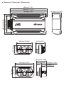
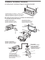
Installation board, etc. (thickness : 15 mm or more)
Tableau d’installation, etc. (épaisseur: 15 mm ou plus)
Tablero de instalación, etc. (grosor: 15 mm o más)
Camera screw thread
(1/4-20 UNC standard)
Pas de vis de l’appareil photo
(standard UNC 1/4-20)
Rosca de tornillo de cámara (1/4-
20 UNC estándar)
Bar mount kit
(Commercially available)
Kit de support de barre
(Vendu séparément)
Juego de montaje de barra
(Vendido por separado)
Example B: Flush Mount
Exemple B: Montage encastré
Ejemplo B: Montaje nivelado
Example C: Handle Mount
Exemple C: Support de poignée
Ejemplo C: Montaje en asidero
Example A: Surface Mount
Exemple A: Montage en surface
Ejemplo A: Montaje en superficie
Installing the unit
/ Installation de l’appareil / Instalación de la unidad
Installing the remote control unit
/ Installation de la télécommande /
Instalación de la mando a distancia
Installation / Installation / Instalación
50 mm
(1-15/16”)
88 mm
(3-7/16”)
Glue
Colle
Pegamento
■
■
(.
r-----------,
! '
I
I
I
I
I
I
____
..

■
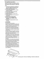
Installation procedure
Read
the
instruction
manual
well
to
select
the
proper
connection and set-
ting. Refer
to
"Connections" on
the
back
side.
1. Remove
the
ignition key and discon-
nect
the
negative 0 terminal
of
the
battery
to prevent short circuits.
2.
Connect
the
battery wire.
3.
Connect
the
ground wire
to
chassis
ground
of
vehicle.
4.
Connect
the
power control wire.
5.
Connect
the
speakers.
6.
Connect
the
remote control unit.
7.
Attach
the
unit.
8. Connect
the
negative 0 terminal
of
the
battery.
9.
Remove
the
Dressing panel.
1 0.Set
the
unit according
to
the
intended usage
(FADER,
FILTER,
OUTPUT).
11.Fix
the
Dressing panel with
screws
securely.
I A CAUTION I
•
Do
not
install
in
the
below
locations;
(Unstable
location
,
In
a
location
that
interferes
with
driving
,
In
a
location
that
gets
wet,
In
a
dusty
location
,
In
a
place
that
gets
hot
,
In
a
place
that
gets
direct
sunlight,
In
a
location
that
gets
hit
by
hot
air)
•
Do
not
install
the
unit
under
the
carpet.
Otherwise
heat
build
-
up
occurs
and
the
unit
may
be
damaged.
•
Install
this
unit
in
a
location
which
allows
heat
to
easily
dissipate.
Once
installed,
do
not
place
any
object
on
top
of
the
unit.
•
The
surface
temperature
of
the
amplifier
will
become
hot
during
use.
Install
the
amplifier
in
a
place
where
people,
resins
,
and
other
substances
that
are
sensitive
to
heat
will
not
come
into
contact
with
it.
•
When
making
a
hole
under
a
seat,
inside
the
trunk,
or
somewhere
else
in
the
vehicle,
check
that
there
is
nothing
hazardous
on
the
opposite
side
such
as
a
gasoline
tank
,
brake
pipe
,
or
wiring
harness
,
and
be
careful
not
to
cause
scratches
or
other
damage.
•
Do
not
install
near
the
dashboard,
rear
tray
,
or
air
bag
safety
parts.
•
The
installation
to
the
vehicle
should
securely
fasten
the
unit
to
a
place
in
which
it
will
not
obstruct
driving.
If
the
unit
comes
off
due
to
a
shock
and
hits
a
person
or
safety
part
,
it
may
cause
injury
or
an
accident.
•
After
installing
the
unit
,
check
to
make
sure
that
elec-
trical
equipment
such
as
the
brake
lamps
,
turn
signal
lamps
and
windshield
wipers
operate
normally.
•
In
order
to
secure
the
Water-proof
&
Dust-proof
per-
formance
(IP67&1P66)
of
this
product,
use
it
with
the
dressing
panel
firmly
attached.
If
the
dressing
panel
is
not
installed
properly,
dust
and
water
may
enter
and
cause
a
malfunction.
'$
"
~
-._-=-----
Dressing
panel/
Panneau d'habillage / Panel
de
rectificaci6n
~

For
U.S.A.
Contains
Transmitter
Module
FCC
ID:
ZWY3008X
IC:
12033A-3008X
FCC
CAUTION
This
transmitter
must
not
be
co
-
located
or
operated
in
conjunction
with
any
other
antenna
or
transmitter.
Changes
or
modifications
not
expressly
approved
by
the
party
responsible
for
compliance
could
void
the
user
's
authority
to
operate
the
equipment.
NOTE:
This
equipment
has
been
tested
and
found
to
comply
with
the
limits
for
a
Class
B
digital
device
,
pursuant
to
part
15
of
the
FCC
Rules.
These
limits
are
designed
to
provide
reasonable
protection
against
harmful
interference
in
a
residential
installation.
This
equipment
generates
,
uses
and
can
radiate
radio
frequency
energy
and
,
if
not
installed
and
used
in
accordance
with
the
instructions
,
may
cause
harmful
interference
to
radio
communications.
However
,
there
is
no
guarantee
that
interference
will
111ot
occur
in
a
particular
installation.
If
this
equipment
does
cause
harmful
interference
to
radio
or
tele-
vision
reception
,
which
can
be
determined
by
turning
the
equipment
off
and
on
,
the
user
is
encouraged
to
try
to
correct
the
interference
by
one
or
more
of
the
following
measures:
•
Reorient
or
relocate
the
receiving
antenna.
•
Increase
the
separation
between
the
equipment
and
receiver.
•
Connect
the
equipment
into
an
outlet
on
a
circuit
different
from
that
to
which
the
receiver
is
connected.
•
Consult
the
dealer
or
an
experienced
radio/TV
technician
for
help
.
Supplier's Declaration
of
Conformity
Trade
Name:
JVC
Products:
COMPACT
BLUETOOTH
4
CHANNEL
DIGITAL
AMPLIFIER
Model
Name:
KS-DR2104DBT
Responsible
Party:
JVCKENWOOD
USA
CORPORATION
2201
East
Dominguez
Street
,
Long
Beach
,
CA
90810
,
U.S.A.
PHONE:
310
639
-
9000
THIS
DEVICE
COMPLIES
WITH
PART
15
OF
THE
FCC
RULES.
OPERATION
IS
SUBJECT
TO
THE
FOLLOWING
TWO
CONDITIONS:
(1)
THIS
DEVICE
MAY
NOT
CAUSE
HARMFUL
INTERFERENCE
,
AND
(2)
THIS
DEVICE
MUST
ACCEPT
ANY
INTERFERENCE
RECEIVED
,
INCLUDING
INTERFERENCE
THAT
MAY
CAUS,E
UNDESIRED
OPERATION
.
For
U.S.A.
and
Canada
I
Pour
/es
Etats-Unis
et
le
Canada
CAUTION ATTENTION
This
equipment
complies
with
FCC/
IC
radiation
exposure
limits
set
forth
for
an
uncontrolled
environment
and
meets
the
FCC
radio
frequency
(RF)
Exposure
Guidelines
and
RSS-102
of
the
IC
radio
frequency
(RF)
Exposure
rules.
This
equipment
should
be
installed
and
operated
keeping
the
radiator
at
least
20
cm
or
more
away
from
person's
body.
Cet
equipement
est
conforme
aux
limites
d'
exposition
aux
rayonnements
enoncees
pour
un
environnement
non
controle
et
respecte
les
regles
les
radioelectriques
(RF)
de
la
FCC
lignes
directrices
d'
exposition
et
d'exposition
aux
frequences
radioelectriques
(RF)
CNR-102
de
l'
IC.
Cet
equipement
doit
etre
installe
et
utilise
en
gardant
une
distance
de
20
cm
ou
plus
entre
le
radiateur
et
le
corps
humain.
For
Canada
I
Pour
le
Canada
IC
(Industry Canada) Notice
This
device
complies
with
Industry
Canada
's
licence-exempt
RSSs
.
Operation
is
subject
to
the
following
two
conditions:
(1)
This
device
may
not
cause
interference
,
and
(2)
this
device
must
accept
an
y
interference
,
including
interference
that
may
cause
undesired
operation
of
the
device.
Note
de
IC
(lndustrie Canada)
Le
present
appareil
est
conforme
aux
CNR
d'
lndustrie
Canada
applicables
aux
appareils
radio
exempts
de
licence.
l.:'exploitation
est
autorisee
aux
deux
conditions
suivantes:
(1)
l'appareil
ne
doit
pas
produire
de
brouillage
;
(2)
l'
utilisateur
de
l'a
ppa
reil
doit
accepter
tout
brouillage
radioelectrique
subi
,
meme
si
le
brouillage
est
susceptible
d'
en
compromettre
le
fonctionnement

CH1
L
CH2
R
CH1
L
CH2
R
CH3
L
CH4
R
White
Blanc
Blanco
White / Blanc / Blanco
Red / Rouge / Rojo
White/Black
Blanc/Noir
Blanco/Negro
Gray
Gris
Gris
Gray/Black
Gris/Noir
Gris/Negro
Green
Vert
Verde
Green/Black
Vert/Noir
Verde/Negro
Purple
Violet
Purpúreo
Purple/Black
Violet/Noir
Purpúreo/Negro
White
Blanc
Blanco
White/Black
Blanc/Noir
Blanco/Negro
Gray
Gris
Gris
Gray/Black
Gris/Noir
Gris/Negro
White
Blanc
Blanco
Gray/Black
Gris/Noir
Gris/Negro
Green
Vert
Verde
Purple/Black
Violet/Noir
Purpúreo/Negro
Green
Vert
Verde
Purple/Black
Violet/Noir
Purpúreo/Negro
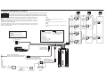
Car fuse box
Boîte de fusible
Caja de fusibles
del automóvil
Ignition key switch
Commutateur à clef
Llave de contacto
Battery
Batterie
Batería
Battery wire (Yellow)
Câble de la batterie (Jaune)
Cable de la batería (Amarillo)
BATT
ACC
CH1
L
CH2
R
CH3-4
MONO
Power control wire (Blue-White)
Câble de commande de l’alimentation (Bleu-Blanc)
Cable de control de alimentación (Azul-Blanco)
AWG 10
AWG 10
AWG 16
AWG 16
L
R
Ground wire (Black)
Câble de masse (Noir)
Cable de masa (Negro)
RCA output
The playback sound of Bluetooth audio is output.
Sortie RCA
Le son de lecture de l’audio Bluetooth est émis.
Salida RCA
Se emite el sonido de reproducción del audio Bluetooth.
Connections / Raccordements / Conexiones
WARNING Remove the ignition key and disconnect the negative terminal of the battery to prevent short circuits.
AVERTISSEMENT Retirer la clé de contact et débrancher la borne négative de la batterie pour éviter les court-circuits.
ADVERTENCIA
Retire la llave de encendido y desconecte el terminal negativo de la batería para evitar cortocircuitos.
In a computer-equipped vehicle, when you remove the terminal of the battery, the memory may
disappear, or a defect may occur in the electrical system of the vehicle. Consult your dealer for further
details.
Dans un véhicule équipé d’un ordinateur, lorsque vous retirez la borne de la batterie, la mémoire
peut disparaître ou un défaut peut se produire dans le système électrique du véhicule. Consultez votre
revendeur pour de plus amples détails.
En un vehículo equipado con ordenador, cuando extrae el terminal de la batería, la memoria puede
desaparecer o puede producirse un defecto en el sistema eléctrico del vehículo. Consulte a su provee-
dor para obtener más detalles.
Fuse (40 A)
NOTE
If you can’t nd the speci ed capacity
fuse at your store etc., consult your
JVC dealer.
Fusible (40 A)
REMARQUE
Si vous ne trouvez pas de fusible de
calibre adéquat dans le commerce,
etc., contacter votre agent JVC.
Fusible (40 A)
NOTA
Si no puede encontrar el fusible de la
capacidad especi cada en su almacén
etc., consulte su distribuidor JVC.
Protective fuse (Commercially available)
Fusible de protection (Vendu séparément)
Fusible de protección (Vendido por separado)
NOTE
After wiring, be sure to insulate and waterproof the connection part.
REMARQUE
Après le câblage, veillez à assurer l’isolation et l’étanchéité de la partie de
connexion.
NOTA
Después de realizar el cableado, asegúrese de aislar y impermeabilizar la pieza
de conexión.
''
''
''
''
''
''
''
''
''
''
D
D
'V'
Oi
i©
: :
: :
: :
''
''
''
''
''
D
J

WARNING
Particular attention must be given to making good electrical contact at the
ampli er-output and speaker terminals.
Poor or loose connections can cause sparking or burning at the terminals
because of the very high power that the ampli er can deliver.
CAUTION
• If sound is not output normally, immediately turn power off and check
connections.
• Be sure to turn the power o before changing the setting of any switch.
• If the fuse blows, check wires for shorts, then replace the fuse with one of
the same rating.
• Check that no unconnected wires or connectors are touching the car body.
Do not remove caps from unconnected wires or connectors to prevent short
circuits.
• Connect the speaker wires to appropriate speaker connectors separately.
Sharing the negative wire of the speaker or grounding speaker wires to the
metal body of the car can cause this unit to fail.
• After installation, check that the brake lamps, turn signal lamps and wind-
shield wipers work properly.
AVERTISSEMENT
Veillez à ce que le contact électrique à la sortie de l’ampli cateur et aux
prises des enceintes soit bien établi.
Un mauvais branchement ou un branchement lâche peut causer des étin-
celles ou un réchau ement des prises du fait de la très grande puissance
de l’ampli cateur.
ATTENTION
• En cas d’anomalie, mettre immédiatement l’appareil hors tension et
véri er tous les raccordements.
• Veiller à mettre l’appareil hors tension avant de changer la position des
commutateurs.
• Si le fusible saute, véri er si les câbles ne sont pas court-circuités, et
remplacer le fusible par un autre fusible de même capacité nominale.
•
Véri er qu’aucun câble ou connecteur non raccordé ne touche la carrosserie
de la voiture. Ne pas retirer les capuchons des câbles ou connecteurs non
raccordés a n d’éviter tout courtcircuit.
• Raccorder séparément les câbles de haut-parleur aux connecteurs de haut-
parleur appropriés. La mise en commun du câble négatif d’un haut-parleur
ou des ls de masse des haut-parleurs à la carrosserie métallique de la
voiture pourrait rendre l’appareil inopérant.
• Après l’installation, véri er que les voyants de frein, les clignotants et les
essuie-glace fonctionnent correctement.
ADVERTENCIA
Debe ponerse especial atención para que se haga un buen contacto eléc-
trico en la salida del ampli cador y en los terminales de los altavoces.
Las conexiones mal hechas o las conexiones ojas pueden causar chispas
o quemaduras en los terminales debido a la potencia muy alta que puede
suministrar el ampli cador.
PRECAUCIÓN
• Si el sonido no sale normalmente, desconecte inmediatamente la alimenta-
ción y compruebe las conexiones.
• No se olvide de desconectar la alimentación antes de cambiar el ajuste de
cualquier conmutador.
• Si el fusible se quema, compruebe que no haya un cortocircuito en los
cables, luego cambie el fusible por uno que tenga el mismo amperaje.
•
Veri que que ninguno de los cables o conectores que están sin conectar se
encuentren tocando la carrocería del automóvil. No retire las tapas de los
cables o conectores que están sin conectar para evitar de que se produzcan
cortocircuitos.
• Conecte los cables del altavoz a los conectores adecuados del altavoz
separadamente. La puesta en contacto de terminales de altavoces distintos,
o la conexión como toma de tierra de los terminales del altavoz al coche del
automóvil, pueden causar daños a la unidad.
•
Después de la instalación, compruebe que las lámparas del freno, luces de
destello y limpiaparabrisas funcionar correctamente.
I A

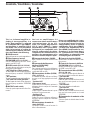
Controls / Contrôles / Controles
This is a 4 channel amplifier in-
cluding 2 stereo amplifiers in a
body. One amplifier is referred
to as ampli er CH1-2 (for FRONT)
and the other is amplifier CH3-4
(for REAR). This unit is compatible
with a large variety of systems by
combining the switches and func-
tions described in the following.
FADER control
Adjusts the front and rear speaker output balance.
Filter frequency control
(FILTER FREQ) (CH.1-2 / CH.3-4)
Sets the cutoff frequency when the “FILTER”
switch is set to “HPF” or “LPF”.
FILTER switch (CH.1-2 / CH.3-4)
This switch allows to apply high-pass or low-pass
ltering to the speaker outputs.
• HPF (High-Pass Filter) position:
The lter outputs the band of higher frequencies
than the frequency set with the “FILTER FREQ”
control.
• OFF position:
The entire bandwidth is output without ltering.
• LPF (Low-Pass Filter) position:
The lter outputs the band of lower frequencies
than the frequency set with the “FILTER FREQ”
control.
OUTPUT mode switch
Selects the speaker output mode. Refer to “Con-
nections”.
Ceci est un amplificateur à 4
canaux avec deux amplificateurs
stéréophoniques en un élé-
ment; l’un appelé Amplificateur
CH1-2 (pour FRONT), l’autre
Ampli cateur CH3-4 (pour REAR).
Cet appareil est compatible avec
diverses con gurations de chaîne,
simplement en sélectionnant les
positions des commutateurs et les
fonctions comme indiqué ci-après.
Commande de fader (FADER)
Règle la balance de sortie des enceintes avant
et arrière.
Commande de fréquence
de ltre (FILTER FREQ)
(CH.1-2 / CH.3-4)
Cette commande permet de préciser la fréquence
de coupure quand le commutateur «FILTER» est
sur la position «HPF» ou «LPF».
Commutateur de ltre (FILTER)
(CH.1-2 / CH.3-4)
Ce commutateur permet d’effectuer un filtrage
des graves, ou des aigus, appliqués vers les haut-
parleurs.
• Position HPF
(Filtre passe-haut):
Le ltre laisse passer les fréquences supérieures à
la fréquence précisée au moyen de la commande
«FILTER FREQ».
• Position OFF:
Le ltre n’agit pas, autrement dit tout le spectre
des fréquences est présent en sortie.
• Position LPF
(Filtre passe-bas):
Le ltre laisse passer les fréquences inférieures à
la fréquence précisée au moyen de la commande
«FILTER FREQ».
Commutateur de mode de
sortie (OUTPUT)
Sélectionne le mode de sortie de l’enceinte. Se
référer à «Raccordements».
Este es un ampli cador de 4 cana-
les con dos ampli cadores estéreo
en un mismo cuerpo. Uno de los
amplificadores recibe el nombre
ampli cador CH1-2 (para FRONT)
y el otro el de ampli cador CH3-4
(para REAR). Combinando los con-
mutadores y las funciones descri-
tas a continuación, esta unidad
amplificadora es compatible con
una amplia gama de sistemas.
Control de fundido (FADER)
Ajusta el balance de salida de los altavoces delan-
teros y traseros.
Control de frecuencia del ltro
(FILTER FREQ) (CH.1-2 / CH.3-4)
Ajusta la frecuencia de corte cuando el conmuta-
dor “FILTER” está en “HPF” o “LPF”.
Conmutador del ltro (FILTER)
(CH.1-2 / CH.3-4)
Este conmutador permite aplicar la ltración de
paso alto o paso bajo a las salidas de los altavoces.
• Posición HPF
(Filtro de paso alto):
El ltro da salida a la banda de frecuencias más
altas que la frecuencia ajustada con el control
“FILTER FREQ”.
• Posición OFF:
Todo el ancho de banda sale sin ltración.
• Posición LPF
(Filtro de paso bajo):
El ltro da salida a la banda de frecuencias más
bajas que la frecuencia ajustada con el control
“FILTER FREQ”.
Conmutador de modo de salida
(OUTPUT)
Selecciona el modo de salida del altavoz. Consulte
“Conexiones”.

8/uetooth function I Fonction de 8/uetooth I Funci6n de 8/uetooth
Supported Bluetooth profiles
-Advanced
Audio
Distribution
Profile
(A2DP)
-AudioNideo
Remote
Control
Profile
(AVRCP)
Supported
Bluetooth
codecs
-aptX
Codec
(aptX)
-
Sub
Band
Codec
(SBC)
-Advanced
Audio
Coding
(AAC)
I NOTE I
•
Depending
on
the
Bluetooth
version
of
the
device,
some
Bluetooth
devices
may
not
be
able
to
con-
nect
to
this
unit.
•
This
unit
may
not
work
with
some
Bluetooth
devices.
•
Signal
conditions
vary,
depending
on
the
surroundings.
Profiles Bluetooth pris
en
charge
-Profile
de
distribution
audio
avance
(A2DP)
-Profile
de
telecommande
audio/video
(AVRCP)
Codecs Bluetooth pris
en
charge
-aptX
Codec
(aptX)
-
Codec
Sous-bande
(SBC)
-Codage
audio
avance
(AAC)
I REMARQUE I
•
En
fonction
de
la
version
Bluetooth
du
peri-
pherique
,
ii
se
peut
que
certains
peripheriques
Bluetooth
ne
puissent
pas
etre
connectes
a
cet
appareil.
•
Cet
appareil
peut
ne
pas
fonctionner
avec
certains
peripheriques
Bluetooth.
•
La
condition
du
signal
varie
en
fonction
de
l'environnement.
Perfiles Bluetooth compatibles
-Perfil
Avanzado
de
Distribucion
de
Audio
(A2DP)
-Perfil
de
Control
Remoto
de
Audio/Video
(AVRCP)
Codecs Bluetooth compatibles
-aptX
Codec
(aptX)
-
Codec
de
sub-banda
(SBC)
-Codificador
avanzado
de
audio
(AAC)
I NOTA I
•
Dependiendo
de
la
version
Bluetooth
del
disposi-
tivo
,
algunos
dispositivos
pueden
no
conectarse
a
esta
unidad.
•
Esta
unidad
puede
no
funcionar
con
algunos
dispositivos
Bluetooth.
•
Las
condiciones
de
la
seiial
varfan
dependiendo
del
entorno.
2
JVC
►
II
•
PAIRI
NG
I 1 2 3 4 5 6 7 I
•I•
■ ■ ■ ■ ■ ■
11
1MIN
••••
MA
X1
-------
•PAE-OUT
I
◄◄
■
Names and functions
[I]
Operation
key
3
To
On
the
remote
control
Playback
/
Pause
Press
►
II
Backward
skip
/
Forward
skip
Press
1
◄◄
/
►►•
Fast-backward
/
Fast-forward
Press
and
hold•
◄◄
/
►►•
PAIRING key (Bluetooth Pairing)
Refer
to
"
Pair
and
connect
a
Bluetooth
device
for
the
first
time
"
below.
rn
EQ
mode
indicator
1:
FLAT,
2:
HARD
ROCK
,
3:
POP,
4:
HIP
HOP,
5:
R & B,
6:
JA71,
7:
CLASSICAL
Volume
indicator
rn
EQkey
Selects
a
preset
equalizer
suitable
to
the
music
genre
.
Each
press
switches
the
modes
as
follows.
[FLAT]
[HARD
ROCK]
[POP]
[HIP
HOP]
[R
&
BJ
[JA71]
[CLASSICAL]
PRE-OUT
key
Press
and
hold
PRE-OUT
to
enter
Pre
-
out
level
control
mode.
@J
PRE-OUT indicator
Illumination
will
light
up
when
the
unit
in
Pre-out
level
control
mode.
[fil Bluetooth
illumination
I]]
Volume
control
knob
Turn
the
knob
to
adjust
the
volume.
Pre-out level control
knob
When
PRE-OUT
indicator
(1±1)
lights
up,
turn
the
knob
to
adjust
the
Pre-out
le
v
el
(-50
dB
[MIN]
to
+
10
dB
[MAX]).
Press
the
knob
to
exitthe
Pre-out
level
control
mode.
Dimmer
setting
knob
Press
and
hold
the
knob
to
turn
on
or
off
the
dimmer.
rn
Red/Rouge/Rojo Red/Rouge/Rojo
Bluetooth illumination
Eclairage Bluetooth
lluminacion Bluetooth 0
Co
nn
ected
Connecte
Co
nectado
~\II,:_
"/
;I\.;::--
Pa
irin
g
..
.
Pai rage
..
.
Empareje
..
.
2. Select [RC-WPAMPBT_vl .**].
•
Bluetooth
illumination
will
light
up
in
red.
•
To
cancel
the
paired
device
and
enter
searching
mode
again,
press
and
hold
PAIRING.
•
Once
pairing
is
completed,
Bluetooth
connection
is
established
automatically.
(Bluetooth
illumination
blinks
rapidly
..
lights
up)
•
Up
to
five
devices
can
be
registered
(paired)
in
total.
If
you
pair
more
than
5
devices
,
the
oldest
registered
device
will
be
deleted.
•
Refer
also
to
the
manual
supplied
with
your
Bluetooth
device.
■
2 Device Connection
A maximum
of
two
Bluetooth audio device can
be connected
at
any time.
1. Connect
the
first Bluetooth device [Al in
advance.
•
Refer
to
"
Pair
and
connect
a
Bluetooth
device
for
the
first
time
'
'.
•
Playback
starts
on
device
[Al
automatically.
2.
Press
and hold PAIRING.
•
Bluetooth
illumination
blinks
in
red
slowly
and
start
paring.
GG
3. Select [RC-WPAMPBT_vl.**l on your second Bluetooth device
[BJ.
•
Bluetooth
illumination
will
light
up
in
red.
4. Pause
the
music on device
[A).
t
5. Operate
the
device
[Bl
to
play music.
~
■
Pair
and
connect a Bluetooth device for
the
first
time
1.
Turn
the
ignition switch
to
the
ACC
ON.
•
When
listening
the
music
on
device
[Al,
pause
the
music
on
device
[Bl,
then
play
the
music
on
device
[A].
•
Bluetooth
illumination
blinks
in
red
slowly
and
start
paring.
•
[RC-WPAMPBT
_
vl
.... ]
will
appear
on
the
Bluetooth
device.
•
The
Bluetooth
® w
ord
mark
and
logos
are
registered
trademarks
ow
ned
by
Bluetooth
SIG,
Inc.
a
nd
any
use
of
such
marks
by
JVCKENWOOD
Corporation
is
under
license.
Other
trademarks
and
trade
names
are
those
of
their
respective
owners.
•
Qualcomm
aptX
is
a
product
of
Qualcomm
Technologies
,
Inc.
and
/
or
its
subsidiaries.
Qualcomm
is
a
trademark
of
Qualcomm
Incorporated
,
registered
in
the
United
States
and
other
countries.
aptX
is
a
trademark
of
Qualcomm
Technologies
International,
Ltd.
,
registered
in
the
United
States
a
nd
other
countries.
-
 1
1
-
 2
2
-
 3
3
-
 4
4
-
 5
5
-
 6
6
-
 7
7
-
 8
8
-
 9
9
-
 10
10
-
 11
11


JVC KS-DR2104DBT Manual de usuario
- Categoría
- Amplificadores de audio para automóviles
- Tipo
- Manual de usuario
en otros idiomas
- français: JVC KS-DR2104DBT Manuel utilisateur
- English: JVC KS-DR2104DBT User manual