YARDGARD Select 328811A Guía de instalación
- Tipo
- Guía de instalación

YARDGARD SELECT
™
Installation Instructions
© 2014 Midwest Air Technologies, Inc • 6700 Wildlife Way, Long Grove, IL 60047 • Customer Service: 800-628-8815
TABLE OF CONTENTS
GETTING STARTED
STAGE 1: FENCE FRAMEWORK INSTALLATION ....1
Tools and Materials .............................1
Fence Framework Parts List ......................1
Step 1: Installing Corner, End, and Gate Posts ........2
Step 2: Installing Line Posts ......................3
Step 3: Installing Post Hardware ...................4
Step 4: Installing Top Rail ........................5
STAGE 2: FENCE PANEL INSTALLATION ..........6
Tools and Materials .............................6
Fence Panels Parts List. . . . . . . . . . . . . . . . . . . . . . . . . . 6
Step 1: Installing Tension Wire ....................7
Step 2: Installing Fence Panels ....................8
STAGE 3: GATE INSTALLATION ..................9
Tools and Materials .............................9
Auto Close Gate Parts List .......................9
Installing Gate ................................10
ESPAÑOL ...................................11
AS A REMINDER...
• HaveyoucompletedyourYARDGARD SELECT
™
Planning
& Purchasing Guide?
• HaveyoupurchasedalltherequiredYARDGARD SELECT
™
components?
• Doyouhaveallrecommendedtoolsandmaterialsready?
Scantoview
installationvideo

YARDGARD SELECT
™
- FENCE FRAMEWORK INSTALLATION INSTRUCTIONS PAGE 1PAGE ii YARDGARD SELECT
™
- FENCE FRAMEWORK INSTALLATION INSTRUCTIONS
FENCE FRAMEWORK - 4´ x 24´
STAGE 1: PARTS LIST
A B C E
A
D
FENCE FRAMEWORK - 4´ x 24´ (1000-035-156) QTY.
A 6-ft Post 3
B
8ft-ft Rail 3
C
Rail Sleeve 3
D
Panel-to-Post Clip 9
E
Panel-to-Rail Clip 18
---
Self-Tapping Screw 28
STAGE 1: FRAMEWORK INSTALLATION
1
POST HARDWARE KIT
F E
H G
J
I
POST HARDWARE KIT (1000-034-742) QTY.
F Rail Connector 1
G Panel-to-Post Bracket 3
H Tension Band 1
I Tension Wire Ratchet 1
J Post Cap 1
---
Self-Tapping Screw 10
E
Panel-to-Rail Clip 1
TOOLS AND MATERIALS
Setting Posts
• PostHoleDigger
• Shovel
• Mixing Tub
• Fast Set Concrete - (1) 50 lb bag per post
• Tape Measure
• String
• Stakes
• Level
Assembling Framework
• Hacksaw or Reciprocating Saw
• Channel-LockPliers
• 1/8˝DrillBit
• CordlessDrill
• 1/4˝NutDriver
• PhillipsBit
• BlackSprayPaint
CongratulationsonyourpurchaseoftheYARDGARD
SELECT
™
FencingSystem.Pleasefollowthestep-by-stepinstructions
forproperinstallation.
• Alwayswearsafetygoggleswhenworkingwithmetalswhichcouldpotentiallydamageyoureyesight.Otherbody
protectionssuchaskneepads,workgloves,etc.arealsosuggested.
• UseyourYARDGARD SELECT
™
Planning&PurchasingGuidetoassistwithyourinstallationprocess.
• Beforeyoubegin,visithomedepot.comoryardgardselect.comtowatchourinstallationvideo.
REMINDER
BEFORE YOU START DIGGING...
• Checklocalcodesregardingheight,locations,etc.Permitsmaybenecessary.
• Consultplatofsurveyorprofessionalsurveyortoensurethatyourfencefootingsarelocatedwithinyourpropertylines.
• Checkwithlocalutilitycompanyforcables,undergroundlines,etc.Achecklistisprovidedbelowforyourconvenience.
£
ElectricityCable
£
SprinklerSystem
£
Gas
£
TV/InternetCable
£
Sewer Pipe
£
Water
£
Others(Listyourownchecklistatthenoteareabelow.)
Setting Posts
• PostHoleDigger
• Shovel
• MixingTub
• FastSetConcrete-
(1) 50 lb bag per post
• TapeMeasure
• String
• Stakes
• Level
GETTING STARTED
TOOLS AND MATERIALS
EachsectionwillhavealistofToolsandMaterialsneededtocompletethejob.Thefollowingisamasterlistofthe
toolsyouwillneedtocompleteallstages ofinstallation.
Assembling Frame and Wire Mesh Panels
• Hacksaw or Reciprocating Saw
• AdjustableWrench
• Channel-LockPliers
• 1/8˝DrillBit
• CordlessDrill
• 1/4˝NutDriver
• PhillipsBit
• WireCutter
• BlackSprayPaint
YARDGARD SELECT
™
- FENCE FRAMEWORK INSTALLATION INSTRUCTIONS

YARDGARD SELECT
™
- FENCE FRAMEWORK INSTALLATION INSTRUCTIONS PAGE 3PAGE 2 YARDGARD SELECT
™
- FENCE FRAMEWORK INSTALLATION INSTRUCTIONS
STEP 1: INSTALLING CORNER, END, AND GATE POSTS
TIP
HaveyourFence Layout GuideavailablebeforebeginninginstallationofyourYARDGARD SELECT
™
FencingSystem.
STAGE 1: FRAMEWORK INSTALLATION
1
• ReferringyourFence Layout Guide,stakelocationsforall
corner,end,andgateposts.Thegatepostsshouldalwaysbe
48˝apart.(Fig.1)
IMPORTANT
Beforeinstallinganyposts,makesurethepost
locationsarenotontopofthemarksidentiedbylocalutilities.
• Digpostholesatallstakedlocationsusingapowerormanual
postholedigger.Eachpostholeshouldbe6˝ wide and 22˝
deep. (Fig. 2)
• Marka“ground”line50˝fromthetopdownoneachpost(Fig.1).
If you are installing on extremely uneven terrain or thick
turf, mark at 51˝.
• Insertmarkedpostsintothecenterofthepostholes.Alignthe
“ground”lineonthepostswiththeground.Addgravelas
necessarytoachievethedesiredheight(Fig2).
TIP
Ifacornerpostholeisinaloworhighspot,youmight
needtoleveltheareabyaddingorremovingtopsoil
(Fig. 3).
• Addfastsetconcretetotheposthole.Astheconcreteis
settingmakesurethepostisplumbonallsidesusinga
level(Fig.4).Checkthatthe“ground”lineisstilllevelwith
theground.Adjustasnecessary.Refertofastsetconcrete
instructionsforsettingtime.
• Crownallconcreteatpostfootingssowaterrunsawayfrom
yourposts.Priortotheconcretecompletelysetting,gently
washconcreteresidueoffpostsurface.
NOTE:Eachpostholewillrequireapproximately(1)50lbbagof
fastsetconcrete.
6˝
50˝
22˝
Post Hole
Ground
Ground Line
Post
Ground
Crown
If the ground is too LOW,
fill in soil to level the surface.
If the ground is too HIGH,
remove soil to level the surface.
Level Line
Fig. 2
Fig. 1
Fig. 3 Leveling Soil Surface for Adjusting Concrete Footings
Fig. 4
6˝
50˝
22˝
Post Hole
Ground
Ground Line
Post
Ground
Crown
If the ground is too LOW,
fill in soil to level the surface.
If the ground is too HIGH,
remove soil to level the surface.
Level Line
Level
48” Width
50˝
From
Ground
Level
GATE POSTS
50˝
From
Ground
Level
If you are installing on
extremely uneven
terrain or thick turf,
mark at 51˝.
6˝
50˝
22˝
Post Hole
Ground
Ground Line
Post
Ground
Crown
If the ground is too LOW,
fill in soil to level the surface.
If the ground is too HIGH,
remove soil to level the surface.
Level Line
NOTE: Useapproximately
(1)one50lbbagoffastset-
tingconcreteforeachpost.
Gravel
GROUND
Line Level
Post
Post
(H)
(D)
Height (H)
Distance (D)
≥ 6%
Grade =
BeforeproceedingtoSTEP 2, determineifthegrade
betweenthelengthofyourinstallationexceeds6%.Visit
homedepot.comoryardgardselect.comforalternative
installation instructions.
STAGE 1: FRAMEWORK INSTALLATION
1
STEP 2: INSTALLING LINE POSTS
• Tieamason’slineposttopostalongyourfencelineandsnap
ittight(Fig.5).
• UsingthelinepostspacingcalculatedonyourFence Layout
Guide, place stakes in line post locations.
• DiglinepostholesfollowingthesameprocessusedinStep1
(Fig. 2).
• Centerlinepostsinholesandaddfastsetconcrete.
• Beforetheconcretesets,raiseorlowerlinepostssothatthe
topofpoststouchthemason’sline(Fig.6).Makesureposts
are plumb.
• Crownallconcreteatpostfootingssowaterrunsawayfrom
yourposts.Priortotheconcretecompletelysetting,gently
washconcreteresidueoffpostsurface.
Terminal
Post
Terminal
Post
Line
Post
Raise
Post Up
Tap Post Down
String Line
Line
Post
Line
Post
NOTE: Top of post should be touching the string.
Togetasimpleandeffectiveguidelineuse
amason’sline:
• Wraparoundnearthetopofthepost
• Loopitaroundahorizontalsection,then
upandoverthetop
• Keepitasclosetothecorner(outside
edge) as possible
Fig. 6
Level out posts to be equal heights from ground
surface.
Fig. 5 Tying a mason’s line
STOP
IMPORTANT
Gatepostsshouldbelevel.Testthegatefor
desiredheightandadjustasnecessary.

YARDGARD SELECT
™
- FENCE FRAMEWORK INSTALLATION INSTRUCTIONS PAGE 5PAGE 4 YARDGARD SELECT
™
- FENCE FRAMEWORK INSTALLATION INSTRUCTIONS
STAGE 1: FRAMEWORK INSTALLATION
1
STEP 3: INSTALLING POSTS
IMPORTANT
Beforeinstallinghardware,makesureyour
postsarecompletelyset.Acordlessdrillisrequiredtoinstallself-
tapping screws.
• Slideatensionbandovereachendpostandgatepost.Slide
twotensionbandsperpendiculartooneanotherovereach
cornerpost(bottomofFig.7).Donottightenthetension
bands until STAGE 2. Install post cap.
• Removerailconnectorcupfromtherailconnectorbaseby
looseningandremovingnutandwasher.(Fig.8a)
• Installrailconnectorbasetotopofeachpostwithself-tapping
screws. (Fig. 8b)
TIP
Pre-drillingholestoinstallrailconnectorcupissuggested.
• Reconnecttherailconnectorcupbacktobase(Fig.8c).
• EachendandgatepostwillrequirethreePanel-to-PostBrackets.
InstalltherstPanel-to-PostBracket1˝belowtherailconnec-
torbasewithself-tappingscrews(Fig.7a).
• ALWAYSinstallthePanel-to-PostBracketswiththeatside
facingoutward.
• Installthesecondbracket20˝belowtherstone(center-to-center).
Installthethirdbracket20˝belowthesecondone(Fig.7a).
• EachcornerpostwillrequiresixPanel-to-PostBrackets.See
Fig.7bforlocationandplacementofbrackets.
Base Bolt Cup Washer
Nut
Base Bolt Cup
Nut
Washer
Self-Tapping Screw
Post
(Top View)
Post
(Side View)
Post
(Front View)
Flush rail connector base with top of post
Base Bolt Cup Washer
Nut
Base Bolt Cup
Nut
Washer
Self-Tapping Screw
Post
(Top View)
Post
(Side View)
Post
(Front View)
Flush rail connector base with top of post
Base Bolt Cup Washer
Nut
Base Bolt Cup
Nut
Washer
Self-Tapping Screw
Post
(Top View)
Post
(Side View)
Post
(Front View)
Flush rail connector base with top of post
1˝
1˝
Panel-to-Post
Bracket
Facing Side
(Facing Outward)
20˝
20˝
20˝
20˝
Tension Band
Tension Band
Fig. 7 Hardware Installation
Fig. 7a
END/GATE Post
END/GATE Post
Fig. 7b
CORNER Post
CORNER Post
IMPORTANT: Inserttensionbandsbeforeinstalling
Panel-to-PostBracketsandRailConnectors.
STAGE 1: FRAMEWORK INSTALLATION
1
STEP 4: INSTALLING TOP RAIL
IMPORTANT
ALWAYSinstallthetoprailwiththeatside
facingoutward.
• Inserttoprailintorailconnectorcup.Fastentherailtothecup
withaself-tappingscrewinsertedfromthecurvedside(Fig.9).
• Positiontherstsectionoftoprailoverlineposts.Toconnect
thenextsectionoftoprail,insertarailsleeveoverthetoprail.
Insertthenextsectionoftoprailintotheoppositeendofthe
railsleeve.
• Fastenrailsleevestotoprailswithself-tappingscrews(Fig.9).
DONOTfastentherailstothelineposts.Ifrailsleevehappensto
belinedupwithalinepost,DONOTfastentherailsleeveatthis
point.DONOTfastenrailsleevefortheterminatingsectionat
thistime.
• Followthissameprocessuntilyoureachtheterminatingsection
ofyourfenceline.
• Measurethelastsectionoftoprailfromtherailsleeve(3˝in)
tothebackoftherailconnectorcup(Fig.10).
• FollowthenumericsequenceinFig.11toconnecttheterminating
toprailtothepost.
• Aftertheterminatingsectionisinplace,fastentherailsleevefor
theterminatingsection.
• DONOTfastenthetoprailtothelinepostsatthistime.Thiswill
bedoneinStage2afterthefencepanelsareinserted.
• Repeatthesameprocessforeachfenceline.
Fig. 9
Fig. 10 Proper Length Measurement
IMPORTANT: Always measure from the inner wall of Rail
Connector Cup to 3˝ inside of top rail sleeve.
Fig. 11 Inserting the Terminating Top Rail
Facing Side
with Flat Surface
(Facing Outward)
TopRailSleeve
Top Rail
Top Rail
Rail Connector
Cup
Rail Connector Cup
Self-Tapping
Screw
Line Post
End/Corner
Post
POST
Top Rail Sleeve
Middle Stop
Top Rail
Top Rail
Cut Off
PROPER LENGTH
From back of rail connector cup
to 3˝ inside of the top rail sleeve.
Rail Connector
Cup
3"
POST
POST
Top Rail Sleeve
Fit Rail Connector Cup to
the terminating Top Rail
Top Rail
Terminating Top Rail
Insert terminating top rail as far
as possible into top rail sleeve
Slide terminating top rail and
rail connector cup to the
rail connector base
Lower the whole top rail assembly
Lift top rail up
Top Rail Sleeve
Top Rail
Fasten the nut
Fig. 8 Rail Connector Assembly
8a
8c8b
Pull Down
to Lock
Facing Side
with Flat Surface
(Facing Outward)
Top
Rail

YARDGARD SELECT
™
- FENCE FRAMEWORK INSTALLATION INSTRUCTIONS PAGE 7PAGE 6 YARDGARD SELECT
™
- FENCE FRAMEWORK INSTALLATION INSTRUCTIONS
TENSION WIRE (1000-034-747)
TENSION WIRE (1000-034-747) QTY.
K
Tension Wire
200´ Roll
1
Panel-to-Wire Clip 100
STAGE 2: FENCE PANEL INSTALLATION
2
FENCE PANELS (1000-034-736)
FENCE PANELS (1000-034-736) QTY.
L 8’ Fence Panel Section 3
M
Panel Clip 12
TOOLS AND MATERIALS
Installing Tension Wire
• TapeMeasure
• Screwdriver(Phillips/Blade)
• AdjustableWrench
• WireCutter
• AdjustablePliers
• CordlessDrill
Installing Fence Panels
• WireCutter
STAGE 2: FENCE PANEL INSTALLATION
2
STEP 1: INSTALLING TENSION WIRE
• Positionthetensionband3˝fromtheground(Fig.12).
• Attachthetensionwireratchet(includedinthePostHardware
Kit)tothetensionbandandtightencarriageboltusingan
adjustablewrench(Fig.12).
• Duplicatethisstepattheoppositecorner,end,orgatepost.
• Measurethedistancebetweenthetwopostsandadd1˝to
thatmeasurement.Cuttensionwiretosize.(Fig.13)
• Threadtensionwirethroughholeinrstratchetandwrapus-
ingadjustablewrenchmaking3to4rotations(Fig.13and14).
• Stretchtensionwiretotensionwireratchetattheoppositeend
ofthefenceline.Repeatthestepsaboveandrotateuntilwire
istight.
• Repeatforeachfenceline.
Fig. 12 Tension Band Installation
Fig. 13 Tension Wire Insertion
Fig. 14 Tighten Tension Wire
STAGE 2: PARTS LIST
3˝
TensionBand
TensionWireRatchet
Insert tension wire
throughholes
AdjustableWrench

YARDGARD SELECT
™
- FENCE FRAMEWORK INSTALLATION INSTRUCTIONS PAGE 9PAGE 8 YARDGARD SELECT
™
- FENCE FRAMEWORK INSTALLATION INSTRUCTIONS
STAGE 2: FENCE PANEL INSTALLATION
2
STEP 2: INSTALLING FENCE PANELS
IMPORTANT
Fencepanelsshouldbepositionedonthe
outsideofthetensionwire.
• Unfoldonesectionoffencepanel(8´).Attachpaneltoallthree
panel-to-post brackets.
• Liftthefencepanelsectionupintotherail.Insertapanel-to-
railclipinsidetherailconnectorcup.Makesurethetopwireis
seatedinthelipoftheclip.Lockintoplaceusingsuppliedtool.
(Fig. 15)
TIP
Iffencepanelsectionsdon’talign,tappanel-to-railclips
gentlyuntilfencepanelsectionstoucheachother.
• Repeatthisprocessforeach8´section,positioningaclipinthe
centerofeach2´panel(Fig.16).Connecttwopanelstogether
byusingthreepanelclips.
• Continueinstallingin8´sectionsuntilreachingtheendofthe
fenceline.
• Hooktheterminatingpanelsectiontothethreepanel-to-post
bracketsontheterminatingpostandpulltowardtheprevious
panelsection.Iftheterminatingpanelisnotaneven2´you
willneedtocutthepanelattheclosestverticalwireusingwire
cutters.Flippanelsoshortpanelconnectstothreepost-to-
panelclips.Connectthetwopanelsectionswiththreepanel
clips.Securetheterminatingfencepaneltotoprailbyusing
panel-to-rail clips. (Fig. 17)
• Fastenfencepaneltoeachlinepostwithpanel-to-postclips
usingself-tappingscrews.(Fig.18)
• Fastentoprailtoeachlinepostsusingselftappingscrews
insertedfromthecurvedside.
• Attachtensionwiretofencepanelswithpanel-to-wireclipusing
adjustablepliers.Attachoneclipevery2´.
1
2
3
Near center of each mesh panel
Inside of each rail connector cup
In both ends of each sleeve
12 1 1 3 3 1 2
Cut One Panel Short
Re-Connect with
Panel Clips or Hog Rings
Pull Down
to Lock
Panel-to-Rail Clip
Unlocked
Locked
End Panel Connection
2-ft x 4-ft
Fence Panel
Cut One Panel Short
Re-Connect with
Panel Clips or Hog Rings
Pull Down
to Lock
Panel-to-Rail Clip
Unlocked
Locked
End Panel Connection
2-ft x 4-ft
Fence Panel
AUTO CLOSE GATE
AUTO CLOSE GATE (1000-034-737) QTY.
N 4’ Gate 1
O
Gate Latch 1
P
Self-Closing Gate Hinges 1
Q
PVC Post Protector 1
Self-Tapping Screws 5
OPTIONAL (AVAILABLE ON HOMEDEPOT.COM) QTY.
R
Decorative fence
medallion*
4
Decorative fence
medallion*
1
TOOLS AND MATERIALS
• Tape Measure
• AdjustableWrench
• CordlessDrill
• 1/4˝NutDriver
Fig. 15 Fence Panel Installation
Fig. 16 Locations of Panel-to-Rail Clips and
Panel Clips
Fig. 18 Fence Panel InstallationFig. 17 Terminating Panel Installation
STAGE 3: PARTS LIST
Line Post
Cut
Panel Clips
Flippanelsoshortpanelconnectsto
threepost-to-panelclips.
Overlaptheterminatingpaneltothe
lastfull8´ section.
Redfencepanelrepresentstheterminatingpanel.
Self-TappingScrew
Panel-to-Post Clip
STAGE 3: GATE INSTALLATION
3
Cut One Panel Short
Re-Connect with
Panel Clips or Hog Rings
Pull Down
to Lock
Panel-to-Rail Clip
Unlocked
Locked
End Panel Connection
2-ft x 4-ft
Fence Panel
Rail Connector
Wire
Panel-to-Post
Bracket
Panel-to-Rail Clip
Panel-to-Rail Clip Installation
Top Rail
(CutawayView)
Locked
Pull Down
Insert
Locked
Pull Down
Insert
Locked
Pull Down
Insert
*Decorativefencemedallionsoldseparatelyathomedepot.com

YARDGARD SELECT
™
- FENCE FRAMEWORK INSTALLATION INSTRUCTIONS PAGE 11PAGE 10 YARDGARD SELECT
™
- FENCE FRAMEWORK INSTALLATION INSTRUCTIONS
STAGE 3: GATE INSTALLATION
3
• Determinewhichpostwillbethelatchpostandwhichwillbe
thehingepost.
• Looselyinstalltopposthingewithpinpointingupapproximately
8˝fromthetopofthehingepost(Fig.19).
• Looselyinstallself-closingposthingewithpinpointingup
approximately10˝fromthebottomofthehingepost(Fig.19).
• Looselyinstalltopgatehingetogateframeapproximately7˝
fromthetopofthehingepost(Fig.19).
• Looselyinstallself-closinggatehingetogateframeapproxi-
mately7˝fromthebottomofthegate(Fig.19).
• Alignthegatebyplacingitlevelwiththetopofthefence.
Adjustthehingestoallowforfullswing.Tightenallhinges.
• Installgatelatchtothegateframeatthedesiredheight.Install
PVCPostProtectortothelatchpostatwherelatchwillclose.
(Fig. 19)
NOTE: Easy-to-installdoublegateanddecorativefencemedal-
lionsareavailableonhomedepot.com.
48"
Fig. 19 Gate Installation
Top
GATE Hinge
Top
POST Hinge
Self-Closing
GATE Hinge
Self-Closing
POST Hinge
Gate Frame Post
GateLatch
PVC
Post Protector
Hinge Post
LatchPost
Instrucciones de instalación del
YARDGARD SELECT
™
© 2014 Midwest Air Technologies, Inc • 6700 Wildlife Way, Long Grove, IL 60047 • SERVICIO AL CLIENTE: 800-628-8815
ÍNDICE
PRIMEROS PASOS
ETAPA 1: INSTALACIÓN DEL ARMAZÓN
DE LA VALLA ................................13
Herramientasymateriales. . . . . . . . . . . . . . . . . . . . . . . 13
Listadepiezasdelarmazóndelavalla. . . . . . . . . . . . . 13
Paso1:Instalacióndelospostesdeesquina,
deextremoydeportón. . . . . . . . . . . . . . . . . . . . . . . . . 14
Paso2:Instalacióndelospostesdelínea .......... 15
Paso3:Instalacióndelosherrajesdeposte .........16
Paso4:Instalacióndeltravesañosuperior ..........17
ETAPA 2: INSTALACIÓN DE LOS PANELES DE LA
VALLA ...................................... 18
Herramientasymateriales. . . . . . . . . . . . . . . . . . . . . . . 18
Listadepiezasdelospanelesdelavalla ........... 18
Paso1:Instalacióndelalambretensor ............19
Paso2:Instalacióndelospanelesdelavalla ........20
ETAPA 3: INSTALACIÓN DEL PORTÓN ..........21
Herramientasymateriales. . . . . . . . . . . . . . . . . . . . . . . 21
Listadepiezasdelportóndecierreautomático ......21
Instalacióndelportón ..........................22
COMO RECORDATORIO...
• ¿HacompletadosuGuíadeplanicaciónycompra
YARDGARD SELECT™?
• ¿HacompradotodosloscomponentesdelYARDGARD
SELECT™requeridos?
• ¿Tienelistastodaslasherramientasymaterialesreco-
mendados?
Escaneeparaverel
videodeinstalación

PÁGINA 12 YARDGARD SELECT
™
: INSTRUCCIONES DE INSTALACIÓN DEL ARMAZÓN DE LA VALLA YARDGARD SELECT
™
: INSTRUCCIONES DE INSTALACIÓN DEL ARMAZÓN DE LA VALLA PÁGINA 13
Felicitaciones por su compra del Sistema de Vallado YARDGARD SELECT
™
.Porfavor,sigalasinstruccionespasoapaso
pararealizarunainstalacióncorrecta.
• Usesiempreanteojosdeseguridadcuandotrabajeconmetales,yaqueéstospodríandañarlelavista.Tambiénse
sugiereusarotrasproteccionescorporales,talescomorodilleras,guantesdetrabajo,etc.
• UtilicesuGuíadeplanicaciónycompraYARDGARD SELECT
™
paraayudarleconsuprocesodeinstalación.
• Antesdecomenzar,visitehomedepot.comoyardgardselect.comparavernuestrovideodeinstalación.
RECORDATORIO
ANTES DE QUE COMIENCE A EXCAVAR......
• Consulteloscódigoslocalesenrelaciónconlaaltura,lasubicaciones,etc.Esposiblequesenecesitenpermisos.
• Consulteelplanoparcelariooauntopógrafoprofesionalparaasegurarsedequeloscimientosdesuvallaesténubica-
dosdentrodelaslíneasdesupropiedad.
• Consultealacompañíalocaldeserviciospúblicosparaaveriguarlaubicacióndecables,tuberíassubterráneas,etc.A
continuaciónseproporcionaunalistadevericaciónparasuconveniencia.
£
Cable de electricidad
£
Sistema de aspersores
£
Gas
£
CabledeTV/Internet
£
Tuberíadealcantarillado
£
Agua
£
Otros(preparesupropialistadevericacióneneláreadenotas
queseencuentramásadelante.)
Instalación de los postes
• Ahoyadorparapostes
• Pala
• Cubetaparamezclar
• Concretodefraguadorápido:
(1) saco de 50 lb por poste
• Cintamétrica
• Cordel
• Estacas
• Nivel
PRIMEROS PASOS
HERRAMIENTAS Y MATERIALES
CadaseccióntendráunalistadeHerramientasyMaterialesnecesariosparacompletareltrabajo.Acontinuaciónse
presentaunalistamaestradelasherramientasquenecesitaráparacompletartodaslasetapasdeinstalación.
Ensamblaje del armazón y los paneles de malla de alambre
• Sierraparametalesosierraalternativa
• Llaveajustable
• Alicatesajustables
• Brocataladradorade1/8depulgada
• Taladroinalámbrico
• Aprietatuercasde1/4depulgada
• BrocaPhillips
• Cortadordealambre
• BlackSprayPaint
ARMAZÓN DE VALLA DE 4 x 24 PIES
ETAPA 1: LISTA DE PIEZAS
A B C E
A
D
ARMAZÓN DE VALLA DE 4 x 24 PIES
(1000-035-156)
CANT.
A Poste de 6 pies 3
B
Travesaño de 8 pies 3
C
Manga de travesaño 3
D
Clip de panel a poste 9
E
Clip de panel a travesaño 18
---
Tornillo autorroscante 28
ETAPA 1: INSTALACIÓN DEL ARMAZÓN DE LA VALLA
1
KIT DE HERRAJES DE POSTE
F E
H G
J
I
KIT DE HERRAJES DE POSTE (1000-034-742) CANT.
F Conector de travesaño 1
G Soporte de panel a poste 3
H Cinta tensora 1
I
Trinquete para alambre
tensor
1
J
Tapa de poste 1
---
Tornillo autorroscante 10
E
Clip de panel a travesaño 1
HERRAMIENTAS Y
MATERIALES
Instalacióndelospostes
• Ahoyadorparapostes
• Pala
• Cubetaparamezclar
• Concretodefraguadorápido:(1)saco
de 50 lb por poste
• Cintamétrica
• Cordel
• Estacas
• Nivel
Ensamblajedelarmazón
• Sierraparametalesosierraalternativa
• Alicatesajustables
• Brocataladradorade1/8depulgada
• Taladroinalámbrico
• Aprietatuercasde1/4depulgada
• BrocaPhillips
• Pinturanegraenaerosol

PÁGINA 14 YARDGARD SELECT
™
: INSTRUCCIONES DE INSTALACIÓN DEL ARMAZÓN DE LA VALLA YARDGARD SELECT
™
: INSTRUCCIONES DE INSTALACIÓN DEL ARMAZÓN DE LA VALLA PÁGINA 15
ETAPA 1: INSTALACIÓN DEL ARMAZÓN DE LA VALLA
1
PASO 2: INSTALACIÓN DE LOS POSTES DE LÍNEA
• Amarreunposteconcuerdadealbañilalpostealolargode
lalíneadesuvallayapriételormementeapresión(Fig.5).
• Utilizandolaseparacióndelospostesdelíneacalculadaen
su Guía de disposición de la valla,coloqueestacasenlas
ubicacionesdelospostesdelínea.
• Excavelosagujerosparalospostesdelíneasiguiendoel
mismoprocesoutilizadoenelPaso1(Fig.2).
• Centrelospostesdelíneaenlosagujerosyañadaconcreto
defraguadorápido.
• Antesdequeelconcretofragüe,subaobajelospostesde
líneademaneraquesupartesuperiortoquelacuerdadeal-
bañil(Fig.6).Asegúresedequelospostesesténaplomados.
• Coronetodoelconcretoenloscimientosdelospostespara
queelaguacorraalejándosedelospostes.Antesdequeel
concretofragüeporcompleto,lavesuavementelasupercie
de los postes para eliminar los residuos de concreto.
Poste
terminal
Poste
terminal
Poste de
línea
Suba el
poste
Golpee suavemente el
poste hacia abajo
Línea de cordel
Poste de
línea
Poste de
línea
NOTA: La parte superior del poste debería estar
tocando el cordel.
Paraobtenerunaguíasimpleyefectiva,
utiliceunacuerdadealbañil:
• Enróllelacercadelapartesuperiordel
poste
• Hagaunbucleconellaalrededordeuna
secciónhorizontalyluegohaciaarribay
por encima de la parte superior
• Manténgalatancercadelaesquina
(borde exterior) como sea posible
Fig. 6
Nivele los postes para que estén a la misma altura
respecto a la supercie del terreno.
Fig. 5 Amarre de una cuerda de albañil
PASO 1: INSTALACIÓN DE LOS POSTES DE ESQUINA, DE EXTREMO Y DE PORTÓN
CONSEJO
TengadisponiblesuGuíadedisposicióndelavallaantesdecomenzarlainstalacióndesuSistemadeVallado
YARDGARD SELECT™.
ETAPA 1: INSTALACIÓN DEL ARMAZÓN DE LA VALLA
1
• ConsultandosuGuíadedisposicióndelavalla,marquecon
estacaslasubicacionesdetodoslospostesdeesquina,de
extremoydeportón.Lospostesdeportónsiempredeberán
estar separados 48 pulgadas uno de otro. (Fig. 1)
IMPORTANTE
Antesdeinstalarcualquierposte,asegúrese
dequelasubicacionesdelospostesnoestén
encimadelasmarcasidenticadasporlascompañíasdeservi-
ciospúblicoslocales.
• Caveagujerosparaposteentodaslasubicacionesmarcadas
conestacas,utilizandounahoyadorparaposteseléctricoo
manual.Cadaagujeroparapostedeberátener6pulgadasde
anchoy22pulgadasdeprofundidad.(Fig.2)
• Marqueunalíneade“terreno”enlapartedeabajodecada
poste, a 50 pulgadas de su parte superior (Fig. 1). Si está
realizando la instalación en terreno sumamente desigual o
pasto grueso, marque la línea a 51 pulgadas.
• Insertelospostesmarcadosenelcentrodelosagujerospara
poste.Alineeconelterrenolalíneade“terreno”ubicadaen
lospostes.Añadagravasegúnseanecesarioparalograrla
altura deseada (Fig. 2).
CONSEJO
Siunagujeroparapostedeesquinaestáenun
puntobajooalto,podríasernecesarionivelarel
áreaañadiendooquitandotierradelacapasuperior(Fig.3).
• Añadaconcretodefraguadorápidoalagujeroparaposte.
Mientraselconcretoestéfraguando,asegúresedequeel
posteestéaplomadoentodoslosladosutilizandounnivel
(Fig.4).Compruebequelalíneade“terreno”aúnestá
niveladaconelterreno.Hagaajustessegúnseanecesario.
Consultelasinstruccionesdelconcretodefraguadorápido
paraconocereltiempodefraguado.
• Coronetodoelconcretoenloscimentosdelospostespara
queelaguacorraalejándosedelospostes.Antesdequeel
concretohayafraguadoporcompleto,lavesuavementela
superciedelospostesparaeliminarlosresiduosdecon-
creto.
NOTA:Cadaagujeroparaposterequeriráaproximadamente
(1)sacodeconcretodefraguadorápidode50lb.
6˝
50˝
22˝
Post Hole
Ground
Ground Line
Post
Ground
Crown
If the ground is too LOW,
fill in soil to level the surface.
If the ground is too HIGH,
remove soil to level the surface.
Level Line
Fig. 2
Fig. 1
Fig. 3 Nivelación de la supercie de tierra para ajustar los cimien-
tos de concreto
Fig. 4
6˝
50˝
22˝
Agujero para
poste
Terreno
Línea de terreno
Poste
Terreno
Corona
Si el terreno es demasiado BAJO,
rellénelo con tierra para nivelar la superficie.
Si el terreno es demasiado ALTO,
quite tierra para nivelar la superficie.
Línea de nivel
Nivel
48 pulgadas
de ancho
A 51 pulgadas
del nivel del
terreno
POSTES DE
PORTÓN
Si está realizando la
instalación en terreno
sumamente desigual o
pasto grueso, marque
la línea a 51 pulgadas
A 51 pulgadas
del nivel del
terreno
6˝
50˝
22˝
Agujero para
poste
Terreno
Línea de terreno
Poste
Terreno
Corona
Si el terreno es demasiado BAJO,
rellénelo con tierra para nivelar la superficie.
Si el terreno es demasiado ALTO,
quite tierra para nivelar la superficie.
Línea de nivel
NOTA: Utilice aproximada-
mente (1) un saco de 50 lb
deconcretodefraguado
rápidoparacadaposte.
Grava
Antes de proceder al PASO 2, determine si la pendiente
delalongituddesuinstalaciónexcedeel6%.Visiteho-
medepot.comoyardgardselect.comparaobtenerinstruc-
cionesalternativasdeinstalación.
ALTO
TERRENO
Nivel de línea
Poste
Poste
(A)
(D)
Altura (A)
Distancia (D)
≥ 6%
Pendiente =
IMPORTANTE
Lospostesdeportóndeberíanestarnivelados.
Pruebeelportónparadeterminarsitienelaaltura
deseadayajústelosegúnseanecesario.

PÁGINA 16 YARDGARD SELECT
™
: INSTRUCCIONES DE INSTALACIÓN DEL ARMAZÓN DE LA VALLA YARDGARD SELECT
™
: INSTRUCCIONES DE INSTALACIÓN DEL ARMAZÓN DE LA VALLA PÁGINA 17
ETAPA 1: INSTALACIÓN DEL ARMAZÓN DE LA VALLA
1
PASO 4: INSTALACIÓN DEL TRAVESAÑO SUPERIOR
IMPORTANTE
Instale SIEMPREeltravesañosuperiorconel
ladoplanoorientadohaciafuera.
• Inserteeltravesañosuperiorenlacopadelconectordetraves-
año.Fijeeltravesañoalacopaconuntornilloautorroscante
insertadodesdeelladocurvo(Fig.9).
• Posicionelaprimeraseccióndetravesañosuperiorsobre
lospostesdelínea.Paraconectarlasiguientesecciónde
travesañosuperior,inserteunamangadetravesañosobreel
travesañosuperior.Insertelasiguienteseccióndetravesaño
superiorenelextremoopuestodelamangadetravesaño.
• Fijelasmangasdetravesañoalostravesañossuperiorescon
tornillosautorroscantes(Fig.9).NOjelostravesañosalos
postesdelínea.Enelcasodequelamangadetravesañoesté
alineadaconunpostedelínea,NOjelamangadetravesaño
enestemomento.NOjeconsujecioneslamangadetravesa-
ñoparalasecciónterminalenestemomento.
• Sigaelmismoprocesohastaquelleguealasecciónterminalde
lalíneadesuvalla.
• Midalaúltimaseccióndetravesañosuperiordesdelamanga
detravesaño(3pulgadashaciadentro)hastalapartetrasera
delacopadelconectordetravesaño(Fig.10).
• SigalasecuencianuméricadelaFig.11paraconectareltravesa-
ñoterminalsuperioralposte.
• Despuésdequelasecciónterminalestécolocadaensusitio,je
lamangadetravesañoparalasecciónterminal.
• NOjeconsujecioneseltravesañosuperioralospostesdelínea
enestemomento.EstoseharáenlaEtapa2despuésdequese
hayaninsertadolospanelesdelavalla.
• Repitaelmismoprocesoparacadalíneadelavalla.
Fig. 9
Fig. 10 Medición de la longitud apropiada
IMPORTANTE : Mida siempre desde la pared interior de la copa del
conector de travesaño hasta 3 pulgadas en el interior de la manga
del travesaño superior.
Fig. 11 Inserción del travesaño terminal superior
Lado frontal
con superficie plana
(orientada hacia fuera)
Manga del
travesañosuperior
Travesaño
superior
Travesaño
superior
Copa del conector
detravesaño
Copadelconectordetravesaño
Tornillo
autorroscante
Postedelínea
Poste de
extremo/esquina
Poste
Manga del travesaño superior
Tope central
Travesaño superior
Travesaño superior
Límite
LONGITUD APROPIADA
Copa del conector
de travesaño
3"
Desde la parte trasera de la copa
del conector de travesaño hasta 3
pulgadas en el interior de la
manga del travesaño superior
POSTE
POSTE
Travesaño terminal superior
Inserte el travesaño terminal superior
tanto como sea posible en la
manga del travesaño superior
Deslice el travesaño terminal superior y
la copa del conector de travesaño hasta
la base del conector de travesaño
Baje todo el ensamblaje
del travesaño superior
1
Manga del travesaño superior
Travesaño superior
Apriete la tuerca
6
5
4
3
2
Ajuste la copa del
conector de
travesaño en el
travesaño terminal
superior
Suba el travesaño
superior
Travesaño superior
Manga del travesaño superior
POSTE
POSTE
Travesaño terminal superior
Inserte el travesaño terminal superior
tanto como sea posible en la
manga del travesaño superior
Deslice el travesaño terminal superior y
la copa del conector de travesaño hasta
la base del conector de travesaño
Baje todo el ensamblaje
del travesaño superior
1
Manga del travesaño superior
Travesaño superior
Apriete la tuerca
6
5
4
3
2
Ajuste la copa del
conector de
travesaño en el
travesaño terminal
superior
Suba el travesaño
superior
Travesaño superior
Manga del travesaño superior
Pull Down
to Lock
Lado frontal
con superficie plana
(orientada hacia fuera)
Travesañosuperior
ETAPA 1: INSTALACIÓN DEL ARMAZÓN DE LA VALLA
1
PASO 3: INSTALACIÓN DE LOS POSTES
IMPORTANTE
Antesdeinstalarlosherrajes,asegúresede
quelospostesesténcompletamenteasentados.Serequiereun
taladroinalámbricoparainstalarlostornillosautorroscantes.
• Desliceunacintatensorasobrecadapostedeextremoycada
postedeportón.Deslicedoscintastensorasperpendicular-
menteunaaotrasobrecadapostedeesquina(parteinferior
delaFig.7).NoaprietelascintastensorashastalaETAPA 2.
Instale la tapa de poste.
• Retirelacopadelconectordetravesañodelabasedelconec-
tordetravesañoaojandoyquitandolatuercaylaarandela.
(Fig. 8a)
• Instalelabasedelconectordetravesañoenlapartesuperior
de cada poste con tornillos autorroscantes. (Fig. 8b)
CONSEJO
Sesugierepretaladraragujerosparainstalarla
copadelconectordetravesaño.
• Reconectelacopadelconectordetravesañodevueltaala
base (Fig. 8c).
• Cadapostedeextremoydeportónrequerirátressoportes
de panel a poste. Instale el primer soporte de panel a poste 1
pulgadapordebajodelabasedelconectordetravesañocon
tornillos autorroscantes (Fig. 7a).
• InstaleSIEMPRE los soportes de panel a poste con el lado
planoorientadohaciafuera.
• Instaleelsegundosoporte20pulgadaspordebajodelprimero(de
centroacentro).Instaleeltercersoporte20pulgadaspordebajo
del segundo (Fig. 7a).
• Cadapostedeesquinarequeriráseissoportesdepanela
poste.VealaFig.7bparaconocerlaubicaciónycolocación
de los soportes.
Base Perno Copa Arandela
Tuerca
Base
Perno
Copa
Tuerca
Arandela
Tornillo autorroscante
Poste
(vista
superior)
Poste
(vista lateral)
Poste
(vista frontal)
Coloque la base del conector de travesaño al
ras con la parte superior del poste
Base Perno Copa Arandela
Tuerca
Base
Perno
Copa
Tuerca
Arandela
Tornillo autorroscante
Poste
(vista
superior)
Poste
(vista lateral)
Poste
(vista frontal)
Coloque la base del conector de travesaño al
ras con la parte superior del poste
Base Perno Copa Arandela
Tuerca
Base
Perno
Copa
Tuerca
Arandela
Tornillo autorroscante
Poste
(vista
superior)
Poste
(vista lateral)
Poste
(vista frontal)
Coloque la base del conector de travesaño al
ras con la parte superior del poste
Soporte de panel
a poste
Lado frontal
(orientado hacia fuera)
20˝
20˝
20˝
20˝
Cinta tensora
Cinta tensora
1˝
1˝
Fig. 7 Instalación de los herrajes
Fig. 7a
Poste de ESQUINA/PORTÓN
Poste de ESQUINA/PORTÓN
Fig. 7b
Poste de ESQUINA
Poste de ESQUINA
IMPORTANTE: Inserte las cintas tensoras antes de
instalarlossoportesdeposteapanelylosconecto-
resdetravesaño.
Fig. 8 Ensamblaje de conector de travesaño
8a
8c
8b

PÁGINA 18 YARDGARD SELECT
™
: INSTRUCCIONES DE INSTALACIÓN DEL ARMAZÓN DE LA VALLA YARDGARD SELECT
™
: INSTRUCCIONES DE INSTALACIÓN DEL ARMAZÓN DE LA VALLA PÁGINA 19
ETAPA 2: INSTALACIÓN DE LOS PANELES DE LA VALLA
2
PASO 1: INSTALACIÓN DEL ALAMBRE TENSOR
• Posicionelacintatensoraa3pulgadasdelterreno(Fig.12).
• Acopleeltrinqueteparaalambretensor(incluidoenelKitde
herrajesdeposte)enlacintatensorayaprieteelpernodecar-
ruajeutilizandounallaveajustable(Fig.12).
• Repitaestepasoenelposteopuestodeesquina,deextremo
odeportón.
• Midaladistanciaentrelosdospostesyañada1pulgadasa
esamedida.Corteelalambretensorconeltamañodeseado.
(Fig. 13)
• Inserteelalambretensoratravésdelagujeroubicadoenel
primertrinqueteyenrólleloutilizandolallaveajustable,haci-
endode3a4rotaciones(Fig.13y14).
• Estireelalambretensorhastaeltrinqueteparaalambretensor
ubicadoenelextremoopuestodelalíneadelavalla.Repita
lospasosanterioresyrotehastaqueelalambreestétenso.
• Repitaelprocesoparacadalíneadelavalla.
Fig. 12 Instalación de la cinta tensora
Fig. 13 Inserción de la cinta tensora
Fig. 14 Apriete el alambre tensor
3˝
Cinta tensora
Trinqueteparaalambretensor
Inserte el alambre tensor
atravésdelosagujeros
Llaveajustable
ALAMBRE TENSOR (1000-034-747)
ALAMBRE TENSOR (1000-034-747) CANT.
K
Alambre tensor Rollo de
200 pies
1
Clip de panel a alambre 100
ETAPA 2: INSTALACIÓN DE LOS PANELES DE LA VALLA
2
PANELES DE VALLA (1000-034-736)
PANELES DE VALLA (1000-034-736) CANT.
L
Sección de paneles de
valla de 8 pies
3
M
Clip de panel 12
HERRAMIENTAS Y
MATERIALES
Instalacióndelalambretensor
• Cintamétrica
• Destornillador(Phillips/dehojaplana)
• Llaveajustable
• Cortadordealambre
• Alicatesajustables
• Taladroinalámbrico
Instalacióndelospanelesdelavalla
• Cortadordealambre
ETAPA 2: LISTA DE PIEZAS

PÁGINA 20 YARDGARD SELECT
™
: INSTRUCCIONES DE INSTALACIÓN DEL ARMAZÓN DE LA VALLA YARDGARD SELECT
™
: INSTRUCCIONES DE INSTALACIÓN DEL ARMAZÓN DE LA VALLA PÁGINA 21
PORTÓN DE CIERRE AUTOMÁTICO
PORTÓN DE CIERRE AUTOMÁTICO (1000-034-737) CANT.
N Portón de 4 pies 1
O
Pestillo del portón 1
P
Bisagras de portón de
cierre automático
1
Q
Protector de poste de PVC 1
Tornillos autorroscantes 5
OPCIONALES (DISPONIBLES EN HOMEDEPOT.COM) CANT.
R
Medallón decorativo
de vallas*
4
Medallón decorativo
de vallas*
1
HERRAMIENTAS Y
MATERIALES
• Cintamétrica
• Llaveajustable
• Taladroinalámbrico
• Aprietatuercasde1/4depulgada
ETAPA 3: LISTA DE PIEZAS
ETAPA 3: INSTALACIÓN DEL PORTÓN
3
*Elmedallóndecorativodevallassevendeporseparadoen
homedepot.com
ETAPA 2: INSTALACIÓN DE LOS PANELES DE LA VALLA
2
PASO 2: INSTALACIÓN DE LOS PANELES DE LA VALLA
IMPORTANTE
Lospanelesdelavallasedeberánposicionar
en el exterior del alambre tensor.
• Desdobleunaseccióndepanelesdevalla(8pies).Acopleel
panel a los tres soportes de panel a poste.
• Subalaseccióndepanelesdevallahaciaelinteriordel
travesaño.Inserteunclipdepanelatravesañoenelinterior
delacopadelconectordetravesaño.Asegúresedequeel
alambresuperiorestéasentadoenelrebordedelclip.Blo-
quéeloenlaposicióncorrecta.(Fig.15)
CONSEJO
Silasseccionesdepanelesdelavallanosealin-
ean,golpeesuavementelosclipsdepanelatravesañohasta
quelasseccionesdepanelesdelavallasetoquenunaaotra.
• Repitaesteprocesoparacadasecciónde8pies,posicionando
un clip en el centro de cada panel de 2 pies (Fig. 16). Conecte
dospanelesjuntosutilizandotresclipsdepanel.
• Continúeinstalandoenseccionesde8pieshastaquellegueal
naldelalíneadelavalla.
• Enganchelaseccióndelpanelterminalalostressoportesde
panelaposteubicadosenelposteterminalyjálelahaciala
seccióndepanelprevia.Sielpanelterminalnomideexacta-
mente2pies,seránecesariocortarelpanelenelalambre
verticalmáscercanoutilizandoelcortadordealambre.Voltee
elpaneldemaneraqueelpanelcortoseconecteatresclips
de poste a panel. Conecte las dos secciones de panel con tres
clipsdepanel.Fijeelpanelterminaldelavallaaltravesaño
superiorutilizandoclipsdepanelatravesaño.(Fig.17)
• Fijeelpaneldelavallaacadapostedelíneaconclipsde
panelaposteutilizandotornillosautorroscantes.(Fig.18)
• Fijeeltravesañosuperioracadapostedelíneautilizandotornil-
losautorroscantesinsertadosdesdeelladocurvo.
• Fijeelalambretensoralospanelesdelavallaconelclipde
panelaalambre,utilizandolosalicatesajustables.Instaleun
clip cada 2 pies.
1
2
3
Cerca del centro de cada panel de malla
Dentro de la cada copa de conector de travesaño
En ambos extremos de cada manga
12 1 1 3 3 1
2
Fig. 15 Instalación de los paneles de la valla
Fig. 16 Ubicaciones de los clips de panel a
travesaño y los clips de panel
Fig. 17 Instalación del panel terminal
Corte
Clips de panel
Volteeelpaneldemaneraqueelpanel
corto se conecte a tres clips de poste
a panel.
Superponga el panel terminal a la
últimasecciónde8piescompleta.
Elpanelrojodelavallarepresentaelpanelterminal.
Cut One Panel Short
Re-Connect with
Panel Clips or Hog Rings
Pull Down
to Lock
Panel-to-Rail Clip
Unlocked
Locked
End Panel Connection
2-ft x 4-ft
Fence Panel
Cut One Panel Short
Re-Connect with
Panel Clips or Hog Rings
Pull Down
to Lock
Panel-to-Rail Clip
Unlocked
Locked
End Panel Connection
2-ft x 4-ft
Fence Panel
Fig. 18 Instalación de los paneles de la valla
Postedelínea
Tornillo
autorroscante
Clip de panel a poste
Cut One Panel Short
Re-Connect with
Panel Clips or Hog Rings
Pull Down
to Lock
Panel-to-Rail Clip
Unlocked
Locked
End Panel Connection
Panel de
valla de
2 x 4 pies
Conectordetravesaño
Alambre
Soporte de
panel a poste
Clipdepanelatravesaño
Instalacióndelclipdepanelatravesaño
Travesañosuperior
(vistadecorte
transversal)
Jale hacia abajo
para bloquear
Bloqueado
Inserte
Jale hacia abajo
para bloquear
Bloqueado
Inserte
Jale hacia abajo
para bloquear
Bloqueado
Inserte

PÁGINA 22 YARDGARD SELECT
™
: INSTRUCCIONES DE INSTALACIÓN DEL ARMAZÓN DE LA VALLA
ETAPA 3: INSTALACIÓN DEL PORTÓN
3
• Determinequéposteseráelpostedelpestilloyquéposte
seráelpostedelasbisagras.
• Instalelabisagradelpostesuperiorsinapretarla,conelpasa-
dororientadohaciaarriba,aproximadamentea8pulgadasde
la parte superior del poste de las bisagras (Fig. 19).
• Instalelabisagradepostedecierreautomáticosinapretarla,
conelpasadororientadohaciaarriba,aproximadamentea10
pulgadasdelaparteinferiordelpostedelasbisagras(Fig.19).
• Instalelabisagrasuperiordelportónsinapretarlaenel
armazóndelportónaproximadamentea7pulgadasdela
parte superior del poste de las bisagras (Fig. 19).
• Instalelabisagradeportóndecierreautomáticosinapretarla
enelarmazóndelportónaproximadamentea7pulgadasde
laparteinferiordelportón(Fig.19).
• Alineeelportóncolocándolodemaneraqueesténiveladocon
lapartesuperiordelavalla.Ajustelasbisagrasparapermitir
un giro completo. Apriete todas las bisagras.
• Instaleelpestillodelportónenelarmazóndelportónalaal-
tura deseada. Instale el protector de poste de PVC en el poste
delpestilloenelcualsecerraráelpestillo.(Fig.19)
NOTA :Puedeconseguirunportóndoblefácildeinstalary
medallonesdecorativosdevallasenhomedepot.com.
48"
Fig. 19 Instalación del portón
Bisagra
superior del
PORTÓN
Bisagrasupe-
rior del POSTE
Bisagrade
PORTÓN de
cierreautomático
Bisagrade
POSTE de cierre
automático
Armazónde
portón
Poste
Pestillo de
portón
Protector de
poste de PVC
Poste de las
bisagras
Poste del pestillo
Transcripción de documentos
YARDGARD SELECT™ Installation Instructions Scan to view installation video TABLE OF CONTENTS GETTING STARTED STAGE 1: FENCE FRAMEWORK INSTALLATION. . . . . 1 STAGE 3: GATE INSTALLATION. . . . . . . . . . . . . . . . . . . 9 Tools and Materials. . . . . . . . . . . . . . . . . . . . . . . . . . . . . . 1 Tools and Materials. . . . . . . . . . . . . . . . . . . . . . . . . . . . . . 9 Fence Framework Parts List. . . . . . . . . . . . . . . . . . . . . . . 1 Auto Close Gate Parts List . . . . . . . . . . . . . . . . . . . . . . . . 9 Step 1: Installing Corner, End, and Gate Posts. . . . . . . . . 2 Installing Gate. . . . . . . . . . . . . . . . . . . . . . . . . . . . . . . . . 10 Step 2: Installing Line Posts . . . . . . . . . . . . . . . . . . . . . . . 3 Step 3: Installing Post Hardware. . . . . . . . . . . . . . . . . . . . 4 ESPAÑOL. . . . . . . . . . . . . . . . . . . . . . . . . . . . . . . . . . . . 11 Step 4: Installing Top Rail . . . . . . . . . . . . . . . . . . . . . . . . . 5 STAGE 2: FENCE PANEL INSTALLATION. . . . . . . . . . . 6 AS A REMINDER... Tools and Materials. . . . . . . . . . . . . . . . . . . . . . . . . . . . . . 6 • Have you completed your YARDGARD SELECT™ Planning & Purchasing Guide? Fence Panels Parts List. . . . . . . . . . . . . . . . . . . . . . . . . . 6 Step 1: Installing Tension Wire . . . . . . . . . . . . . . . . . . . . . 7 • Have you purchased all the required YARDGARD SELECT™ components? Step 2: Installing Fence Panels. . . . . . . . . . . . . . . . . . . . . 8 • Do you have all recommended tools and materials ready? © 2014 Midwest Air Technologies, Inc • 6700 Wildlife Way, Long Grove, IL 60047 • Customer Service: 800-628-8815 1 GETTING STARTED STAGE 1: FRAMEWORK INSTALLATION Congratulations on your purchase of the YARDGARD SELECT™ Fencing System. Please follow the step-by-step instructions for proper installation. TOOLS AND MATERIALS Setting Posts • Always wear safety goggles when working with metals which could potentially damage your eyesight. Other body protections such as knee pads, work gloves, etc. are also suggested. • • • • • • • • • Use your YARDGARD SELECT™ Planning & Purchasing Guide to assist with your installation process. • Before you begin, visit homedepot.com or yardgardselect.com to watch our installation video. REMINDER Post Hole Digger Shovel Mixing Tub Fast Set Concrete - (1) 50 lb bag per post Tape Measure String Stakes Level Assembling Framework • • • • • • • BEFORE YOU START DIGGING... • Check local codes regarding height, locations, etc. Permits may be necessary. • Consult plat of survey or professional surveyor to ensure that your fence footings are located within your property lines. • Check with local utility company for cables, underground lines, etc. A check list is provided below for your convenience. £ Electricity Cable £ Sprinkler System £ Gas £ TV/Internet Cable STAGE 1: PARTS LIST £ Sewer Pipe £ Water £ Others (List your own check list at the note area below.) FENCE FRAMEWORK - 4´ x 24´ A B C E TOOLS AND MATERIALS Each section will have a list of Tools and Materials needed to complete the job. The following is a master list of the tools you will need to complete all stages of installation. Setting Posts Assembling Frame and Wire Mesh Panels • • • • • • • • • • • • • • • • • Post Hole Digger Shovel Mixing Tub Fast Set Concrete (1) 50 lb bag per post Tape Measure String Stakes Level Hacksaw or Reciprocating Saw Adjustable Wrench Channel-Lock Pliers 1/8˝ Drill Bit Cordless Drill 1/4˝ Nut Driver Phillips Bit Wire Cutter Black Spray Paint A YARDGARD SELECT™ - FENCE FRAMEWORK INSTALLATION INSTRUCTIONS FENCE FRAMEWORK - 4´ x 24´ (1000-035-156) QTY. A 6-ft Post 3 B 8ft-ft Rail 3 C Rail Sleeve 3 D Panel-to-Post Clip 9 E Panel-to-Rail Clip 18 --- Self-Tapping Screw 28 POST HARDWARE KIT POST HARDWARE KIT (1000-034-742) F J H PAGE ii D Hacksaw or Reciprocating Saw Channel-Lock Pliers 1/8˝ Drill Bit Cordless Drill 1/4˝ Nut Driver Phillips Bit Black Spray Paint I E G YARDGARD SELECT™ - FENCE FRAMEWORK INSTALLATION INSTRUCTIONS QTY. F Rail Connector 1 G Panel-to-Post Bracket 3 H Tension Band 1 I Tension Wire Ratchet 1 J Post Cap 1 --- Self-Tapping Screw 10 E Panel-to-Rail Clip 1 PAGE 1 1 1 STAGE 1: FRAMEWORK INSTALLATION STEP 2: INSTALLING LINE POSTS STEP 1: INSTALLING CORNER, END, AND GATE POSTS • Tie a mason’s line post to post along your fence line and snap it tight (Fig. 5). TIP Have your Fence Layout Guide available before beginning installation of your YARDGARD SELECT™ Fencing System. • Referring your Fence Layout Guide, stake locations for all corner, end, and gate posts. The gate posts should always be 48˝ apart. (Fig. 1) • Using the line post spacing calculated on your Fence Layout Guide, place stakes in line post locations. Fig. 1 IMPORTANT Gate posts should be level. Test the gate for desired height and adjust as necessary. IMPORTANT Before installing any posts, make sure the post locations are not on top of the marks identified by local utilities. • Dig line post holes following the same process used in Step 1 (Fig. 2). • Center line posts in holes and add fast set concrete. If you are installing on extremely uneven terrain or thick turf, 50˝ From mark at 51˝. 48” Width • Dig post holes at all staked locations using a power or manual post hole digger. Each post hole should be 6˝ wide and 22˝ deep. (Fig. 2) GATE POSTS 50˝ From Ground Level Ground Level TIP If a corner post hole is in a low or high spot, you might need to level the area by adding or removing top soil (Fig. 3). • Add fast set concrete to the post hole. As the concrete is setting make sure the post is plumb on all sides using a level (Fig. 4). Check that the “ground” line is still level with the ground. Adjust as necessary. Refer to fast set concrete instructions for setting time. • Crown all concrete at post footings so water runs away from your posts. Prior to the concrete completely setting, gently wash concrete residue off post surface. Fig. 5 Tying a mason’s line To get a simple and effective guide line use a mason’s line: • Wrap around near the top of the post • Loop it around a horizontal section, then up and over the top • Keep it as close to the corner (outside edge) as possible • Before the concrete sets, raise or lower line posts so that the top of posts touch the mason’s line (Fig. 6). Make sure posts are plumb. • Crown all concrete at post footings so water runs away from your posts. Prior to the concrete completely setting, gently wash concrete residue off post surface. • Mark a “ground” line 50˝ from the top down on each post (Fig. 1). If you are installing on extremely uneven terrain or thick turf, mark at 51˝. • Insert marked posts into the center of the post holes. Align the “ground” line on the posts with the ground. Add gravel as necessary to achieve the desired height (Fig 2). STAGE 1: FRAMEWORK INSTALLATION 6˝ Fig. 6 Level out posts to be equal heights from ground surface. 6˝ Fig. 2 Tap Post Down Ground Line Crown Ground Line 22˝ String Line Crown Ground Ground 50˝ Post 22˝ Post Hole Post Hole Raise Post Up 50˝ Post NOTE: Use approximately (1) one 50 lb bag of fast setting concrete for each post. Ground Terminal Post Ground Line Post Line Post Line Post Terminal Post Gravel NOTE: Top of post should be touching the string. Fig. 3 Leveling Soil Surface for Adjusting Concrete Footings NOTE: Each post hole will require approximately (1) 50 lb bag of fast set concrete. If the ground is too LOW, If the ground is too HIGH, If the ground isfilltoo LOW, is too in soil to level the surface. If the ground remove soilHIGH, to level the surface. fill in soil to level the surface. remove soil to level the surface. Level Line Level Line STOP Before proceeding to STEP 2, determine if the grade between the length of your installation exceeds 6%. Visit homedepot.com or yardgardselect.com for alternative installation instructions. 6˝ Grade = Level Fig. 4 Height (H) ≥ 6% Distance (D) Ground Line Crown (H) Line Level 50˝ Post 22˝ Post Hole Post Post (D) Ground Ground GROUND PAGE 2 YARDGARD SELECT™ - FENCE FRAMEWORK INSTALLATION INSTRUCTIONS If the ground is too LOW, If the ground is too HIGH, YARDGARD SELECT™ - FENCE FRAMEWORK INSTALLATION INSTRUCTIONS PAGE 3 1 1 STAGE 1: FRAMEWORK INSTALLATION STEP 3: INSTALLING POSTS STEP 4: INSTALLING TOP RAIL Fig. 7 Hardware Installation Fig. 7a END/GATE Post IMPORTANT Before installing hardware, make sure your posts are completely set. A cordless drill is required to install selftapping screws. Fig. 7b CORNER Post IMPORTANT 1˝ • Slide a tension band over each end post and gate post. Slide two tension bands perpendicular to one another over each corner post (bottom of Fig. 7). Do not tighten the tension bands until STAGE 2. Install post cap. 1˝ Panel-to-Post Bracket 20˝ • Remove rail connector cup from the rail connector base by loosening and removing nut and washer. (Fig. 8a) 20˝ Facing Side (Facing Outward) • Reconnect the rail connector cup back to base (Fig. 8c). • Each end and gate post will require three Panel-to-Post Brackets. Install the first Panel-to-Post Bracket 1˝ below the rail connector base with self-tapping screws (Fig. 7a). 20˝ 20˝ • ALWAYS install the Panel-to-Post Brackets with the flat side facing outward. facing outward. Facing Side Top Rail ALWAYS install the top rail with the flat side Tension Band Tension Band Rail Connector Cup Facing Side with Flat Surface (Facing Outward) • Insert top rail into rail connector cup. Fasten the rail to the cup with a self-tapping screw inserted from the curved side (Fig. 9). Self-Tapping Screw Top Rail Sleeve • Position the first section of top rail over line posts. To connect the next section of top rail, insert a rail sleeve over the top rail. Insert the next section of top rail into the opposite end of the rail sleeve. Pu to End/Corner Post Top Rail Line Post • Follow this same process until you reach the terminating section of your fence line. Fig. 10 Proper Length Measurement • Measure the last section of top rail from the rail sleeve (3˝ in) to the back of the rail connector cup (Fig. 10). IMPORTANT: Always measure from the inner wall of Rail Connector Cup to 3˝ inside of top rail sleeve. Cut Off Top Rail • After the terminating section is in place, fasten the rail sleeve for the terminating section. • Each corner post will require six Panel-to-Post Brackets. See Fig. 7b for location and placement of brackets. Top Rail with Flat Surface (Facing Outward) • Follow the numeric sequence in Fig. 11 to connect the terminating top rail to the post. • Install the second bracket 20˝ below the first one (center-to-center). Install the third bracket 20˝ below the second one (Fig. 7a). Rail Connector Cup Fig. 9 • Fasten rail sleeves to top rails with self-tapping screws (Fig. 9). DO NOT fasten the rails to the line posts. If rail sleeve happens to be lined up with a line post, DO NOT fasten the rail sleeve at this point. DO NOT fasten rail sleeve for the terminating section at this time. • Install rail connector base to top of each post with self-tapping screws. (Fig. 8b) TIP Pre-drilling holes to install rail connector cup is suggested. STAGE 1: FRAMEWORK INSTALLATION • DO NOT fasten the top rail to the line posts at this time. This will be done in Stage 2 after the fence panels are inserted. PROPER LENGTH 3" Top Rail From back of rail connector cup to 3˝ inside of the top rail sleeve. POST • Repeat the same process for each fence line. Middle Stop Rail Connector Cup IMPORTANT: Insert tension bands before installing Panel-to-Post Brackets and Rail Connectors. Fig. 8 Rail Connector Assembly Top Rail Sleeve Fig. 11 Inserting the Terminating Top Rail 8a Base Bolt Cup Washer Base Bolt Nut Nut Base Bolt Cup Washer Cup Washer Fit Rail Connector Cup to the terminating Top Rail Nut Base Bolt Cup Washer Nut POST Insert terminating top rail as far as possible into top rail sleeve Terminating Top Lift top rail up Rail Top Rail Lower the whole top rail assembly Top Rail Sleeve 8b END/GATE Post 8c CORNER Post Flush rail connector base with top of post Slide terminating top rail and rail connector cup to the rail connector base Post (Top View) Nut Base Bolt Cup Washer Nut Flush rail connector base with of post Base Bolt CuptopWasher Post Post (Side View) (Front View) Self-Tapping Screw (Front View) Self-Tapping Screw Fasten the nut Top Rail Post (Top View) PAGE 4 Post Post (Side View) POST YARDGARD SELECT™ - FENCE FRAMEWORK INSTALLATION INSTRUCTIONS Top Rail Sleeve YARDGARD SELECT™ - FENCE FRAMEWORK INSTALLATION INSTRUCTIONS PAGE 5 2 2 STAGE 2: FENCE PANEL INSTALLATION STAGE 2: FENCE PANEL INSTALLATION STEP 1: INSTALLING TENSION WIRE TOOLS AND MATERIALS • Position the tension band 3˝ from the ground (Fig. 12). Installing Tension Wire • • • • • • Fig. 12 Tension Band Installation Tape Measure Screwdriver (Phillips/Blade) Adjustable Wrench Wire Cutter Adjustable Pliers Cordless Drill • Attach the tension wire ratchet (included in the Post Hardware Kit) to the tension band and tighten carriage bolt using an adjustable wrench (Fig. 12). Adjustable Wrench Tension Band • Duplicate this step at the opposite corner, end, or gate post. • Measure the distance between the two posts and add 1˝ to that measurement. Cut tension wire to size. (Fig. 13) Installing Fence Panels • Wire Cutter • Thread tension wire through hole in first ratchet and wrap using adjustable wrench making 3 to 4 rotations (Fig. 13 and 14). • Stretch tension wire to tension wire ratchet at the opposite end of the fence line. Repeat the steps above and rotate until wire is tight. 3˝ Tension Wire Ratchet Fig. 13 Tension Wire Insertion • Repeat for each fence line. STAGE 2: PARTS LIST Insert tension wire through holes TENSION WIRE (1000-034-747) TENSION WIRE (1000-034-747) K Tension Wire 200´ Roll Panel-to-Wire Clip QTY. 1 Fig. 14 Tighten Tension Wire 100 FENCE PANELS (1000-034-736) FENCE PANELS (1000-034-736) PAGE 6 QTY. L 8’ Fence Panel Section 3 M Panel Clip 12 YARDGARD SELECT™ - FENCE FRAMEWORK INSTALLATION INSTRUCTIONS YARDGARD SELECT™ - FENCE FRAMEWORK INSTALLATION INSTRUCTIONS PAGE 7 2 3 STAGE 2: FENCE PANEL INSTALLATION STEP 2: INSTALLING FENCE PANELS STAGE 3: GATE INSTALLATION Fig. 15 Fence Panel Installation TOOLS AND MATERIALS Panel-to-Rail Clip Installation IMPORTANT Fence panels should be positioned on the outside of the tension wire. Insert • Unfold one section of fence panel (8´). Attach panel to all three panel-to-post brackets. Insert If fence panel sections don’t align, tap panel-to-rail clips gently until fence panel sections touch each other. • Hook the terminating panel section to the three panel-to-post brackets on the terminating post and pull toward the previous panel section. If the terminating panel is not an even 2´ you will need to cut the panel at the closest vertical wire using wire cutters. Flip panel so short panel connects to three post-topanel clips. Connect the two panel sections with three panel clips. Secure the terminating fence panel to top rail by using panel-to-rail clips. (Fig. 17) Locked Top Rail Pull Down to Lock Panel-to-Post Bracket Locked Wire 2-ft x 4-ft Fence Panel STAGE 3: PARTS LIST Fig. 16 Locations of Panel-to-Rail Clips and Panel Clips 1 2 3 AUTO CLOSE GATE Near center of each mesh panel Inside of each rail connector cup In both ends of each sleeve 2 1 1 Panel-to-Rail Clip Panel-to-Rail Clip 1 3 3Unlocked 1 Unlocked 2 AUTO CLOSE GATE (1000-034-737) Pull Down Pull Down to Lock to Lock Locked Locked 2-ft x 4-ft 2-ft x 4-ft Fence Panel Fence Panel • Attach tension wire to fence panels with panel-to-wire clip using adjustable pliers. Attach one clip every 2´. Fig. 17 Terminating Panel Installation Red fence panel represents the terminating panel. Overlap the terminating panel to the last full 8´ section. Flip panel so short panel connects to three post-to-panel clips. Tape Measure Adjustable Wrench Cordless Drill 1/4˝ Nut Driver Unlocked (Cutaway View) • Fasten fence panel to each line post with panel-to-post clips using self-tapping screws. (Fig. 18) • Fasten top rail to each line posts using self tapping screws inserted from the curved side. Locked Locked Panel-to-Rail Clip Panel-to-Rail Clip • Repeat this process for each 8´ section, positioning a clip in the center of each 2´ panel (Fig. 16). Connect two panels together by using three panel clips. • Continue installing in 8´ sections until reaching the end of the fence line. • • • • Pull DownPull Down Rail Connector • Lift the fence panel section up into the rail. Insert a panel-torail clip inside the rail connector cup. Make sure the top wire is seated in the lip of the clip. Lock into place using supplied tool. (Fig. 15) TIP Pull Down Insert N 4’ Gate 1 O Gate Latch 1 P Self-Closing Gate Hinges 1 Q PVC Post Protector 1 Self-Tapping Screws 5 * Decorative fence medallion sold separately at homedepot.com Fig. 18 Fence Panel Installation End Panel Connection OPTIONAL (AVAILABLE ON HOMEDEPOT.COM) Line Post Cut One Panel Short QTY. Re-Connect with Panel Clips or Hog Rings R Self-Tapping Screw QTY. Decorative fence medallion* 4 Decorative fence medallion* 1 Panel-to-Post Clip End Panel Connection Cut Panel Clips Cut One Panel Short End Panel Connection Cut One Panel Short PAGE 8 Re-Connect with Panel Clips or Hog Rings Re-Connect with Panel Clips or Hog Rings YARDGARD SELECT™ - FENCE FRAMEWORK INSTALLATION INSTRUCTIONS YARDGARD SELECT™ - FENCE FRAMEWORK INSTALLATION INSTRUCTIONS PAGE 9 3 Instrucciones de instalación del YARDGARD SELECT™ STAGE 3: GATE INSTALLATION • Determine which post will be the latch post and which will be the hinge post. Escanee para ver el video de instalación • Loosely install top post hinge with pin pointing up approximately 8˝ from the top of the hinge post (Fig. 19). • Loosely install self-closing post hinge with pin pointing up approximately 10˝ from the bottom of the hinge post (Fig. 19). • Loosely install top gate hinge to gate frame approximately 7˝ from the top of the hinge post (Fig. 19). • Loosely install self-closing gate hinge to gate frame approximately 7˝ from the bottom of the gate (Fig. 19). • Align the gate by placing it level with the top of the fence. Adjust the hinges to allow for full swing. Tighten all hinges. • Install gate latch to the gate frame at the desired height. Install PVC Post Protector to the latch post at where latch will close. (Fig. 19) NOTE: Easy-to-install double gate and decorative fence medallions are available on homedepot.com. Top GATE Hinge Fig. 19 Gate Installation Top POST Hinge ÍNDICE 48" Gate Latch PRIMEROS PASOS ETAPA 1: INSTALACIÓN DEL ARMAZÓN DE LA VALLA. . . . . . . . . . . . . . . . . . . . . . . . . . . . . . . . . 13 ETAPA 3: INSTALACIÓN DEL PORTÓN . . . . . . . . . . . 21 Herramientas y materiales. . . . . . . . . . . . . . . . . . . . . . . 13 Lista de piezas del portón de cierre automático . . . . . . . 21 Lista de piezas del armazón de la valla. . . . . . . . . . . . . 13 Hinge Post Paso 1: Instalación de los postes de esquina, PVC Post Protector de extremo y de portón . . . . . . . . . . . . . . . . . . . . . . . . . 14 Paso 2: Instalación de los postes de línea . . . . . . . . . . . 15 Self-Closing POST Hinge Latch Post Paso 3: Instalación de los herrajes de poste. . . . . . . . . . 16 Paso 4: Instalación del travesaño superior. . . . . . . . . . . 17 ETAPA 2: INSTALACIÓN DE LOS PANELES DE LA VALLA. . . . . . . . . . . . . . . . . . . . . . . . . . . . . . . . . . . . . . . 18 Herramientas y materiales. . . . . . . . . . . . . . . . . . . . . . . 18 Self-Closing GATE Hinge Herramientas y materiales. . . . . . . . . . . . . . . . . . . . . . . 21 Instalación del portón . . . . . . . . . . . . . . . . . . . . . . . . . . . 22 COMO RECORDATORIO... • ¿Ha completado su Guía de planificación y compra YARDGARD SELECT™? • ¿Ha comprado todos los componentes del YARDGARD SELECT™ requeridos? • ¿Tiene listas todas las herramientas y materiales recomendados? Lista de piezas de los paneles de la valla. . . . . . . . . . . . 18 Paso 1: Instalación del alambre tensor . . . . . . . . . . . . . 19 Gate Frame PAGE 10 Post YARDGARD SELECT™ - FENCE FRAMEWORK INSTALLATION INSTRUCTIONS Paso 2: Instalación de los paneles de la valla. . . . . . . . . 20 YARDGARD - FENCE FRAMEWORK INSTRUCTIONS PAGE 11 © 2014 SELECT Midwest™Air Technologies, Inc INSTALLATION • 6700 Wildlife Way, Long Grove, IL 60047 • SERVICIO AL CLIENTE: 800-628-8815 PRIMEROS PASOS 1 ETAPA 1: INSTALACIÓN DEL ARMAZÓN DE LA VALLA Felicitaciones por su compra del Sistema de Vallado YARDGARD SELECT™. Por favor, siga las instrucciones paso a paso para realizar una instalación correcta. HERRAMIENTAS Y MATERIALES • Use siempre anteojos de seguridad cuando trabaje con metales, ya que éstos podrían dañarle la vista. También se sugiere usar otras protecciones corporales, tales como rodilleras, guantes de trabajo, etc. Instalación de los postes • • • • • Utilice su Guía de planificación y compra YARDGARD SELECT™ para ayudarle con su proceso de instalación. • Antes de comenzar, visite homedepot.com o yardgardselect.com para ver nuestro video de instalación. • • • • RECORDATORIO ANTES DE QUE COMIENCE A EXCAVAR...... • Consulte los códigos locales en relación con la altura, las ubicaciones, etc. Es posible que se necesiten permisos. Ensamblaje del armazón • Consulte el plano parcelario o a un topógrafo profesional para asegurarse de que los cimientos de su valla estén ubicados dentro de las líneas de su propiedad. • • • • • • • • Consulte a la compañía local de servicios públicos para averiguar la ubicación de cables, tuberías subterráneas, etc. A continuación se proporciona una lista de verificación para su conveniencia. £ Cable de electricidad £ Sistema de aspersores £ Gas £ Cable de TV/Internet £ Tubería de alcantarillado £ Agua £ Otros (prepare su propia lista de verificación en el área de notas que se encuentra más adelante.) ETAPA 1: LISTA DE PIEZAS B C E HERRAMIENTAS Y MATERIALES Cada sección tendrá una lista de Herramientas y Materiales necesarios para completar el trabajo. A continuación se presenta una lista maestra de las herramientas que necesitará para completar todas las etapas de instalación. Ensamblaje del armazón y los paneles de malla de alambre Instalación de los postes Ahoyador para postes Pala Cubeta para mezclar Concreto de fraguado rápido: (1) saco de 50 lb por poste Cinta métrica Cordel Estacas Nivel • • • • • • • • • Sierra para metales o sierra alternativa Llave ajustable Alicates ajustables Broca taladradora de 1/8 de pulgada Taladro inalámbrico Aprietatuercas de 1/4 de pulgada Broca Phillips Cortador de alambre Black Spray Paint A KIT DE HERRAJES DE POSTE YARDGARD SELECT™ : INSTRUCCIONES DE INSTALACIÓN DEL ARMAZÓN DE LA VALLA F J H PÁGINA 12 Sierra para metales o sierra alternativa Alicates ajustables Broca taladradora de 1/8 de pulgada Taladro inalámbrico Aprietatuercas de 1/4 de pulgada Broca Phillips Pintura negra en aerosol ARMAZÓN DE VALLA DE 4 x 24 PIES A • • • • • • • • Ahoyador para postes Pala Cubeta para mezclar Concreto de fraguado rápido: (1) saco de 50 lb por poste Cinta métrica Cordel Estacas Nivel I G E D ARMAZÓN DE VALLA DE 4 x 24 PIES (1000-035-156) CANT. A Poste de 6 pies 3 B Travesaño de 8 pies 3 C Manga de travesaño 3 D Clip de panel a poste 9 E Clip de panel a travesaño 18 --- Tornillo autorroscante 28 KIT DE HERRAJES DE POSTE (1000-034-742) CANT. F Conector de travesaño 1 G Soporte de panel a poste 3 H Cinta tensora 1 I Trinquete para alambre tensor 1 J Tapa de poste 1 --- Tornillo autorroscante 10 E Clip de panel a travesaño 1 YARDGARD SELECT™ : INSTRUCCIONES DE INSTALACIÓN DEL ARMAZÓN DE LA VALLA PÁGINA 13 1 1 ETAPA 1: INSTALACIÓN DEL ARMAZÓN DE LA VALLA PASO 2: INSTALACIÓN DE LOS POSTES DE LÍNEA PASO 1: INSTALACIÓN DE LOS POSTES DE ESQUINA, DE EXTREMO Y DE PORTÓN CONSEJO Tenga disponible su Guía de disposición de la valla antes de comenzar la instalación de su Sistema de Vallado YARDGARD SELECT™. • Consultando su Guía de disposición de la valla, marque con estacas las ubicaciones de todos los postes de esquina, de extremo y de portón. Los postes de portón siempre deberán estar separados 48 pulgadas uno de otro. (Fig. 1) Antes de instalar cualquier poste, asegúrese de que las ubicaciones de los postes no estén encima de las marcas identificadas por las compañías de servicios públicos locales. IMPORTANTE IMPORTANTE Los postes de portón deberían estar nivelados. Pruebe el portón para determinar si tiene la altura deseada y ajústelo según sea necesario. POSTES DE PORTÓN • Inserte los postes marcados en el centro de los agujeros para poste. Alinee con el terreno la línea de “terreno” ubicada en los postes. Añada grava según sea necesario para lograr la altura deseada (Fig. 2). Fig. 2 CONSEJO Si un agujero para poste de esquina está en un Ground Line • Añada concreto de fraguado rápido al agujero para poste. Mientras el concreto esté fraguando, asegúrese de que el poste esté aplomado en todos los lados utilizando un nivel (Fig. 4). Compruebe que la línea de “terreno” aún está nivelada con el terreno. Haga ajustes según sea necesario. Consulte las instrucciones del concreto de fraguado rápido para conocer el tiempo de fraguado. • Corone todo el concreto en los cimentos de los postes para que el agua corra alejándose de los postes. Antes de que el concreto haya fraguado por completo, lave suavemente la superficie de los postes para eliminar los residuos de concreto. • Amarre un poste con cuerda de albañil al poste a lo largo de la línea de su valla y apriételo firmemente a presión (Fig. 5). • Utilizando la separación de los postes de línea calculada en su Guía de disposición de la valla, coloque estacas en las ubicaciones de los postes de línea. • Excave los agujeros para los postes de línea siguiendo el mismo proceso utilizado en el Paso 1 (Fig. 2). • Centre los postes de línea en los agujeros y añada concreto de fraguado rápido. • Antes de que el concreto fragüe, suba o baje los postes de línea de manera que su parte superior toque la cuerda de albañil (Fig. 6). Asegúrese de que los postes estén aplomados. Si está realizando la instalación en terreno sumamente desigual o pasto grueso, marque la línea a 51 pulgadas 48 pulgadas de ancho A 51 pulgadas del nivel del terreno A 51 pulgadas del nivel del terreno • Marque una línea de “terreno” en la parte de abajo de cada poste, a 50 pulgadas de su parte superior (Fig. 1). Si está realizando la instalación en terreno sumamente desigual o pasto grueso, marque la línea a 51 pulgadas. punto bajo o alto, podría ser necesario nivelar el área añadiendo o quitando tierra de la capa superior (Fig. 3). Fig. 1 • Cave agujeros para poste en todas las ubicaciones marcadas con estacas, utilizando un ahoyador para postes eléctrico o manual. Cada agujero para poste deberá tener 6 pulgadas de ancho y 22 pulgadas de profundidad. (Fig. 2) ETAPA 1: INSTALACIÓN DEL ARMAZÓN DE LA VALLA • Corone todo el concreto en los cimientos de los postes para que el agua corra alejándose de los postes. Antes de que el concreto fragüe por completo, lave suavemente la superficie de los postes para eliminar los residuos de concreto. Fig. 5 Amarre de una cuerda de albañil Para obtener una guía simple y efectiva, utilice una cuerda de albañil: • Enróllela cerca de la parte superior del poste • Haga un bucle con ella alrededor de una sección horizontal y luego hacia arriba y por encima de la parte superior • Manténgala tan cerca de la esquina (borde exterior) como sea posible Fig. 6 Nivele los postes para que estén a la misma altura respecto a la superficie del terreno. 6˝ Crown Terreno Ground 22˝ Suba el poste Corona Línea de terreno 22˝ Golpee suavemente el poste hacia abajo Línea de cordel 6˝ Poste terminal 50˝ 50˝ Poste Poste de línea Agujero para poste NOTA:Post Utilice aproximadamente (1) un saco de 50 lb Terreno de concreto de fraguado rápido para cada poste. Post Hole Grava Ground Si el terreno es demasiado BAJO, Poste de línea Poste de línea NOTA: La parte superior del poste debería estar tocando el cordel. Si el terreno es demasiado ALTO, Fig. 3 Nivelación superficie de tierra para cimienrellénelo conde tierrala para nivelar la superficie. quite tierra ajustar para nivelarlos la superficie. tos de concreto If the ground is too LOW, fill in soil to level the surface. Poste terminal Línea de nivel If the ground is too HIGH, remove soil to level the surface. Level Line NOTA: Cada agujero para poste requerirá aproximadamente (1) saco de concreto de fraguado rápido de 50 lb. ALTO Nivel de línea Antes de proceder al PASO 2, determine si la pendiente de la longitud de su instalación excede el 6%. Visite ho- 6˝ medepot.com o yardgardselect.com para obtener instrucciones alternativas de instalación. Altura (A) Línea de terreno Pendiente = Distancia (D) ≥ 6% Nivel Corona Terreno 50˝ Poste 22˝ Poste Poste (D) (A) Fig. 4 Agujero para poste Terreno TERRENO PÁGINA 14 YARDGARD SELECT™ : INSTRUCCIONES DE INSTALACIÓN DEL ARMAZÓN DE LA VALLA Si el terreno es demasiado BAJO, rellénelo con tierra para nivelar la superficie. Si el terreno es demasiado ALTO, quite tierra para nivelar la superficie. YARDGARD SELECT™ : INSTRUCCIONES DE INSTALACIÓN DEL ARMAZÓN DE LA VALLA PÁGINA 15 1 1 ETAPA 1: INSTALACIÓN DEL ARMAZÓN DE LA VALLA PASO 3: INSTALACIÓN DE LOS POSTES PASO 4: INSTALACIÓN DEL TRAVESAÑO SUPERIOR Fig. 7 Instalación de los herrajes Fig. 7a Poste de ESQUINA/PORTÓN IMPORTANTE Antes de instalar los herrajes, asegúrese de Fig. 7b Poste de ESQUINA 1˝ 1˝ Soporte de panel a poste 20˝ 20˝ • Retire la copa del conector de travesaño de la base del conector de travesaño aflojando y quitando la tuerca y la arandela. (Fig. 8a) • Instale la base del conector de travesaño en la parte superior de cada poste con tornillos autorroscantes. (Fig. 8b) copa del conector de travesaño. • Reconecte la copa del conector de travesaño de vuelta a la base (Fig. 8c). 20˝ 20˝ • Cada poste de extremo y de portón requerirá tres soportes de panel a poste. Instale el primer soporte de panel a poste 1 pulgada por debajo de la base del conector de travesaño con tornillos autorroscantes (Fig. 7a). Lado frontal con superficie plana (orientada hacia fuera) Travesaño superior lado plano orientado hacia fuera. • Inserte el travesaño superior en la copa del conector de travesaño. Fije el travesaño a la copa con un tornillo autorroscante insertado desde el lado curvo (Fig. 9). Cinta tensora Cinta tensora • Instale el segundo soporte 20 pulgadas por debajo del primero (de centro a centro). Instale el tercer soporte 20 pulgadas por debajo del segundo (Fig. 7a). • Cada poste de esquina requerirá seis soportes de panel a poste. Vea la Fig. 7b para conocer la ubicación y colocación de los soportes. IMPORTANTE: Inserte las cintas tensoras antes de instalar los soportes de poste a panel y los conectores de travesaño. Tuerca Copa Arandela Tuerca Base Travesaño superior Poste de línea Perno Base Perno Arandela • Siga el mismo proceso hasta que llegue a la sección terminal de la línea de su valla. Base Límite Travesaño superior • Siga la secuencia numérica de la Fig. 11 para conectar el travesaño terminal superior al poste. LONGITUD APROPIADA • Después de que la sección terminal esté colocada en su sitio, fije la manga de travesaño para la sección terminal. Perno 8b • NO fije con sujeciones el travesaño superior a los postes de línea en este momento. Esto se hará en la Etapa 2 después de que se hayan insertado los paneles de la valla. Poste de ESQUINA/PORTÓN • Repita el mismo proceso para cada línea de la valla. Poste (vista Tuerca Tuerca superior) Perno de Copa Arandelaal Coloque la baseBase del conector travesaño Base ras con la parte superior del poste Poste Poste (vista frontal) Poste Copa Perno Tornillo autorroscante Fig. 11 Inserción del travesaño terminal superior Inserte el travesaño terminal superior tanto como sea posible en la manga travesañoterminal superiorsuperior Inserte del el travesaño tanto como sea posible en la manga del travesaño superior Poste (vista superior) Arandela YARDGARD SELECT™ : INSTRUCCIONES DE INSTALACIÓN DEL ARMAZÓN DE LA VALLA Tornillo autorroscante Travesaño term inal superior 3 3 2 2 Suba el travesaño superior Suba el travesaño superior Travesaño sup Travesaño term erior inal superior 4 Baje todo el ensamblaje 4 travesaño superior del Travesaño sup erior Manga del travesaño superior Baje todo el ensamblaje del travesaño superior Deslice el travesaño terminal superior y la copa del conector de travesaño hasta la base del conector de travesaño Deslice el travesaño terminal superior y la copa del conector de travesaño hasta la base del conector de travesaño POSTE POSTE Manga del travesaño superior 6 6 5 5 Apriete la tuerca Travesaño superior Apriete la tuerca Travesaño superior Manga del travesaño superior Poste PÁGINA 16 Manga del travesaño superior 8c Poste de ESQUINA Coloque la base del conector de travesaño al ras con la parte superior del poste (vista lateral) Travesaño superior Tope central Copa del conector de travesaño POSTE Arandela 3" Desde la parte trasera de la copa del conector de travesaño hasta 3 pulgadas en el interior de la manga del travesaño superior Poste POSTE Copa Poste de extremo/esquina IMPORTANTE : Mida siempre desde la pared interior de la copa del conector de travesaño hasta 3 pulgadas en el interior de la manga del travesaño superior. travesaño en eldel Ajuste la copa travesaño terminal conector de superior travesaño en el travesaño terminal superior Tuerca Tuerca Copa Arandela Tornillo autorroscante Fig. 10 Medición de la longitud apropiada 1 Ajuste la copa del 1 conector de Copa Copa del conector de travesaño P t Fig. 8 Ensamblaje de conector de travesaño Base 8a Perno Lado frontal • Posicione la primera sección de travesaño superior sobre los postes de línea. Para conectar la siguiente sección de travesaño superior, inserte una manga de travesaño sobre el travesaño superior. Inserte la siguiente sección de travesaño superior en el extremo opuesto de la manga de travesaño. • Mida la última sección de travesaño superior desde la manga de travesaño (3 pulgadas hacia dentro) hasta la parte trasera de la copa del conector de travesaño (Fig. 10). • Instale SIEMPRE los soportes de panel a poste con el lado plano orientado hacia fuera. Travesaño superior con superficie plana (orientada hacia fuera) Manga del travesaño superior • Fije las mangas de travesaño a los travesaños superiores con tornillos autorroscantes (Fig. 9). NO fije los travesaños a los postes de línea. En el caso de que la manga de travesaño esté alineada con un poste de línea, NO fije la manga de travesaño en este momento. NO fije con sujeciones la manga de travesaño para la sección terminal en este momento. Lado frontal (orientado hacia fuera) CONSEJO Se sugiere pretaladrar agujeros para instalar la Copa del conector de travesaño Fig. 9 IMPORTANTE Instale SIEMPRE el travesaño superior con el que los postes estén completamente asentados. Se requiere un taladro inalámbrico para instalar los tornillos autorroscantes. • Deslice una cinta tensora sobre cada poste de extremo y cada poste de portón. Deslice dos cintas tensoras perpendicularmente una a otra sobre cada poste de esquina (parte inferior de la Fig. 7). No apriete las cintas tensoras hasta la ETAPA 2. Instale la tapa de poste. ETAPA 1: INSTALACIÓN DEL ARMAZÓN DE LA VALLA Manga del travesaño superior YARDGARD SELECT™ : INSTRUCCIONES DE INSTALACIÓN DEL ARMAZÓN DE LA VALLA PÁGINA 17 2 2 ETAPA 2: INSTALACIÓN DE LOS PANELES DE LA VALLA ETAPA 2: INSTALACIÓN DE LOS PANELES DE LA VALLA PASO 1: INSTALACIÓN DEL ALAMBRE TENSOR HERRAMIENTAS Y MATERIALES • Posicione la cinta tensora a 3 pulgadas del terreno (Fig. 12). Instalación del alambre tensor • • • • • • Fig. 12 Instalación de la cinta tensora Cinta métrica Destornillador (Phillips/de hoja plana) Llave ajustable Cortador de alambre Alicates ajustables Taladro inalámbrico Instalación de los paneles de la valla • Cortador de alambre • Acople el trinquete para alambre tensor (incluido en el Kit de herrajes de poste) en la cinta tensora y apriete el perno de carruaje utilizando una llave ajustable (Fig. 12). Llave ajustable Cinta tensora • Repita este paso en el poste opuesto de esquina, de extremo o de portón. • Mida la distancia entre los dos postes y añada 1 pulgadas a esa medida. Corte el alambre tensor con el tamaño deseado. (Fig. 13) • Inserte el alambre tensor a través del agujero ubicado en el primer trinquete y enróllelo utilizando la llave ajustable, haciendo de 3 a 4 rotaciones (Fig. 13 y 14). 3˝ Trinquete para alambre tensor Fig. 13 Inserción de la cinta tensora • Estire el alambre tensor hasta el trinquete para alambre tensor ubicado en el extremo opuesto de la línea de la valla. Repita los pasos anteriores y rote hasta que el alambre esté tenso. ETAPA 2: LISTA DE PIEZAS Inserte el alambre tensor a través de los agujeros • Repita el proceso para cada línea de la valla. ALAMBRE TENSOR (1000-034-747) ALAMBRE TENSOR (1000-034-747) K CANT. Alambre tensor Rollo de 200 pies 1 Clip de panel a alambre 100 Fig. 14 Apriete el alambre tensor PANELES DE VALLA (1000-034-736) PANELES DE VALLA (1000-034-736) PÁGINA 18 CANT. L Sección de paneles de valla de 8 pies 3 M Clip de panel 12 YARDGARD SELECT™ : INSTRUCCIONES DE INSTALACIÓN DEL ARMAZÓN DE LA VALLA YARDGARD SELECT™ : INSTRUCCIONES DE INSTALACIÓN DEL ARMAZÓN DE LA VALLA PÁGINA 19 2 3 ETAPA 2: INSTALACIÓN DE LOS PANELES DE LA VALLA PASO 2: INSTALACIÓN DE LOS PANELES DE LA VALLA Fig. 15 Instalación de los paneles de la valla en el exterior del alambre tensor. Bloqueado Bloqueado Bloqueado Conector de travesaño Clip de panel a travesaño • Suba la sección de paneles de valla hacia el interior del travesaño. Inserte un clip de panel a travesaño en el interior de la copa del conector de travesaño. Asegúrese de que el alambre superior esté asentado en el reborde del clip. Bloquéelo en la posición correcta. (Fig. 15) Unlocked Pull Down to Lock Alambre Soporte de panel a poste Locked Panel de valla de 2 x 4 pies • Repita este proceso para cada sección de 8 pies, posicionando un clip en el centro de cada panel de 2 pies (Fig. 16). Conecte dos paneles juntos utilizando tres clips de panel. • Fije el panel de la valla a cada poste de línea con clips de panel a poste utilizando tornillos autorroscantes. (Fig. 18) ETAPA 3: LISTA DE PIEZAS Fig. 16 Ubicaciones de los clips de panel a travesaño y los clips de panel 1 2 3 PORTÓN DE CIERRE AUTOMÁTICO Cerca del centro de cada panel de malla Dentro de la cada copa de conector de travesaño En ambos extremos de cada manga 2 1 1 1 3 3 1 Panel-to-Rail Clip 2 PORTÓN DE CIERRE AUTOMÁTICO (1000-034-737) Panel-to-Rail Clip Unlocked Superponga el panel terminal a la última sección de 8 pies completa. to Lock Locked Locked 2-ft x 4-ft 2-ft x 4-ft Fence Panel Fence Panel Fig. 18 Instalación de los paneles de la valla Voltee el panel de manera que el panel corto se conecte a tres clips de poste a panel. N Portón de 4 pies 1 O Pestillo del portón 1 P Bisagras de portón de cierre automático 1 Q Protector de poste de PVC 1 Tornillos autorroscantes 5 Pull Down Pull Down to Lock • Fije el alambre tensor a los paneles de la valla con el clip de panel a alambre, utilizando los alicates ajustables. Instale un clip cada 2 pies. El panel rojo de la valla representa el panel terminal. CANT. Unlocked • Fije el travesaño superior a cada poste de línea utilizando tornillos autorroscantes insertados desde el lado curvo. Fig. 17 Instalación del panel terminal Cinta métrica Llave ajustable Taladro inalámbrico Aprietatuercas de 1/4 de pulgada Panel-to-Rail Clip Travesaño superior (vista de corte transversal) CONSEJO • Enganche la sección del panel terminal a los tres soportes de panel a poste ubicados en el poste terminal y jálela hacia la sección de panel previa. Si el panel terminal no mide exactamente 2 pies, será necesario cortar el panel en el alambre vertical más cercano utilizando el cortador de alambre. Voltee el panel de manera que el panel corto se conecte a tres clips de poste a panel. Conecte las dos secciones de panel con tres clips de panel. Fije el panel terminal de la valla al travesaño superior utilizando clips de panel a travesaño. (Fig. 17) • • • • Jale hacia Jaleabajo hacia Jale abajo hacia abajo para bloquear para bloquear para bloquear InserteInserte Inserte • Desdoble una sección de paneles de valla (8 pies). Acople el panel a los tres soportes de panel a poste. • Continúe instalando en secciones de 8 pies hasta que llegue al final de la línea de la valla. HERRAMIENTAS Y MATERIALES Instalación del clip de panel a travesaño IMPORTANTE Los paneles de la valla se deberán posicionar Si las secciones de paneles de la valla no se alinean, golpee suavemente los clips de panel a travesaño hasta que las secciones de paneles de la valla se toquen una a otra. ETAPA 3: INSTALACIÓN DEL PORTÓN OPCIONALES (DISPONIBLES EN HOMEDEPOT.COM) End Panel Connection Poste de línea Cut One Panel Short * El medallón decorativo de vallas se vende por separado en homedepot.com Re-Connect with Panel Clips or Hog Rings R Tornillo autorroscante CANT. Medallón decorativo de vallas* 4 Medallón decorativo de vallas* 1 Clip de panel a poste End Panel Connection Corte Clips de panel PÁGINA 20 Cut One Panel Short End Panel Connection Re-Connect with Panel Clips or Hog Rings YARDGARD SELECT™ : INSTRUCCIONES DE INSTALACIÓNRe-Connect DEL ARMAZÓN DE LA VALLA Cut One Panel Short with Panel Clips or Hog Rings YARDGARD SELECT™ : INSTRUCCIONES DE INSTALACIÓN DEL ARMAZÓN DE LA VALLA PÁGINA 21 3 ETAPA 3: INSTALACIÓN DEL PORTÓN • Determine qué poste será el poste del pestillo y qué poste será el poste de las bisagras. • Instale la bisagra del poste superior sin apretarla, con el pasador orientado hacia arriba, aproximadamente a 8 pulgadas de la parte superior del poste de las bisagras (Fig. 19). • Instale la bisagra de poste de cierre automático sin apretarla, con el pasador orientado hacia arriba, aproximadamente a 10 pulgadas de la parte inferior del poste de las bisagras (Fig. 19). • Instale la bisagra superior del portón sin apretarla en el armazón del portón aproximadamente a 7 pulgadas de la parte superior del poste de las bisagras (Fig. 19). • Instale la bisagra de portón de cierre automático sin apretarla en el armazón del portón aproximadamente a 7 pulgadas de la parte inferior del portón (Fig. 19). • Alinee el portón colocándolo de manera que esté nivelado con la parte superior de la valla. Ajuste las bisagras para permitir un giro completo. Apriete todas las bisagras. Bisagra superior del PORTÓN • Instale el pestillo del portón en el armazón del portón a la altura deseada. Instale el protector de poste de PVC en el poste del pestillo en el cual se cerrará el pestillo. (Fig. 19) NOTA : Puede conseguir un portón doble fácil de instalar y medallones decorativos de vallas en homedepot.com. Bisagra superior del POSTE Fig. 19 Instalación del portón 48" Pestillo de portón Poste de las bisagras Protector de poste de PVC Bisagra de POSTE de cierre automático Poste del pestillo Bisagra de PORTÓN de cierre automático Armazón de portón PÁGINA 22 Poste YARDGARD SELECT™ : INSTRUCCIONES DE INSTALACIÓN DEL ARMAZÓN DE LA VALLA-
 1
1
-
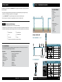 2
2
-
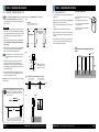 3
3
-
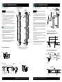 4
4
-
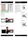 5
5
-
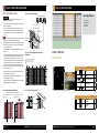 6
6
-
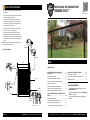 7
7
-
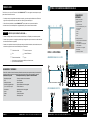 8
8
-
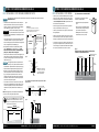 9
9
-
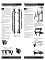 10
10
-
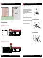 11
11
-
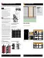 12
12
-
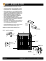 13
13


YARDGARD Select 328811A Guía de instalación
- Tipo
- Guía de instalación
Artículos relacionados


Otros documentos
-
Everbilt 18624 Instrucciones de operación
-
Sierra Pacific Industries 502953 Guía de instalación
-
-
-
-
 Veranda 73013798 Instrucciones de operación
-
-
-
-
Freedom 73008701 Guía de instalación
