
BEFORE INSTALLING:
All installations should comply with National and local Electrical
codes.
If you have any doubts concerning installation contact a quali-
fied licensed electrician.
CAUTION:
To reduce the risk of fire, do not install closer than 1 inch to cabinet
wall or in compartment smaller than 12 inches by 12 inches by
12 inches.
IMPORTANT SAFETY INSTRUCTIONS
a) Read all instructions
b) Do not conceal or extend exposed conductors through
a building wall, floor or ceiling
c) Install this system in dry or damp locations only
d) To reduce risk of fire and burns, do not install this lighting
system where the exposed bare conductors can be
shorted or contact any conductive materials
e) To reduce the risk of fire and overheating, make sure all
connections are tight
f) Do not install any luminaire closer than 6 inches (15.25cm)
from any curtain, or similar combustible materials
g) Power supply has two distinct sections for line voltage
(AC Input) and low voltage (DC Output). It is important
to keep the line voltage and the low voltage wires separate.
h) Turn off electrical power before modifying the lighting
system in any way
We’re here to help 866-558-5706
Hrs: M-F 9am to 5pm EST
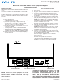
Kichler 6TL-Series (24V) and 4TL-Series (12V) Power Supplies
Installation Instructions
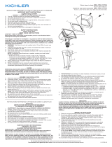
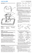
LOW VOLTAGE WIRE
COMPARTMENT
120V TERMINAL BLOCKMOUNTING SCREW
Date Issued: 04/08/16 IS-6TD24V6-US
NOTE: Kichler 6TL-Series (24V) and 4TL-Series
(12V) Power Supplies are not compatible with
dimmers when used in conjunction with tape
light controllers.
THIS DEVICE COMPLIES WITH PART 15 OF THE
FCC RULES. OPERATION IS SUBJECT TO THE
FOLLOWING TWO CONDITIONS: (1) THIS DE-
VICE MAY NOT CAUSE HARMFUL INTERFER-
ANCE, AND (2) THIS DEVICE MUST ACCEPT
ANY INTERFERANCE RECEIVED, INCLUDING
INTERFERANCE THAT MAY CAUSE UNDESIRED
OPERATION.
SAVE THESE INSTRUCTIONS
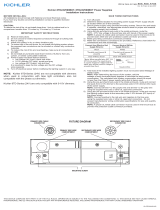
1) Turn off power
2) Determine desired location for mounting power supply. Power
supply should be located within 25’ of first luminaire.
3) Secure power supply using provided mounting screws.
Secure into wall studs if possible, otherwise, use appropriate
anchors rated for proper wall material and hanging weight
(not included).
4) Using the pre-punched knock-outs in the metal enclosure,
route and connect the 120V line voltage to the primary side
(AC Input) of the power supply.
NOTE: Connect 120V line wire to terminal location marked
“L”, connect 120V neutral line to wire marked “N” and connect
ground wire to terminal marked with ground ( ). Tighten
screws to ensure wires are secured.
NOTE: A proper UL listed cable connector must be used in
the knock-outs to provide strain relief and wire protection.
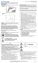
5) Total load of the installed lighting system must not exceed
rated Wattage of power supply.
NOTE: After determining the layout of the system, add the
wattage of each luminaire/fixture together to calculate the
total system consumption. The calculated total system
consumption should be equal or less than the Class 2 power
supply rating that is being used.
6) Using the pre-punched knock-outs in the metal enclosure,
route and connect the lighting system leads to the secondary
side (DC Output) of the power supply.
NOTE: Connect positive to the red wire and negative to the
black wire using the supplied wire nuts or other UL ap
proved connectors.
NOTE: A proper UL listed cable connector must be used in
the knock-outs to provide wire protection.
7) Using supplied 4x40 Philips head screws, secure wiring
compartment lid using size PH1 driver (not included).
NOTE: Do not over tighten screws to avoid stripping
threads.

ANTES DE INSTALAR:
Todas las instalaciones deben cumplir con los códigos de
Electricidad Local y Nacional.
Si usted tiene dudas relacionadas con la instalación, consulte a
un electricista calificado con licencia.
PRECAUCIÓN:
Para reducir el riesgo de incendio, no instale a menos de 1 pulgada
de la pared del gabinete o en un compartimiento menor de 12
pulgadas por 12 pulgadas por 12 pulgadas.
INSTRUCCIONES IMPORTANTES SOBRE SEGURIDAD
a) Lea todas las instrucciones
b) No cubra ni extienda los conductores expuestos a
través de la pared, el piso o el techo de un edificio
c) Instale este sistema solo en lugares secos o húmedos
d) Para reducir el riesgo de incendios y quemaduras, no
instale este sistema de iluminación donde los conductores
sin aislamiento expuestos puedan provocar un corto
circuito o tener contacto con algún material conductivo
e) Para reducir el riesgo de incendio o recalentamiento,
asegúrese de que todas las conexiones estén apretadas
f) No instale ninguna luminaria a menos de 6 pulgadas
(15.25cm) de cualquier cortina o material combustible
similar
g) El suministro de energía tiene dos secciones diferentes
para el voltaje de línea (Entrada de CA) y bajo voltaje
(Salida de CD). Es importante mantener separados los
cables de voltaje de línea y bajo voltaje.
h) Desconecte la energía eléctrica antes de modificar el
sistema de iluminación de cualquier forma
CONSERVE ESTAS INSTRUCCIONES
1) Apague la energía eléctrica
2) Determine la ubicación deseada para montar el suministro
de energía eléctrica. El suministro de energía eléctrica
deberá estar ubicado dentro de un radio de 25’ de la primera
luminaria.
We’re here to help 866-558-5706
Hrs: M-F 9am to 5pm EST
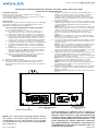
Suministros de Energía Eléctrica Kichler Serie 6TL (24V) y Serie 4TL (12V)
Instrucciones de Instalación
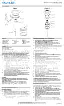
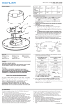
COMPARTIMENTO
DE CABLES DE BAJO
VOLTAJE
BLOQUE DE TERMINALES
DE 120V
TORNILLO DE MONTAJE
Date Issued: 04/08/16 IS-6TD24V6-US
NOTA: Los suministros de energía eléctrica Serie
6TL (24V) y 4TL-Series (12V) de Kichler no son
compatibles con los atenuadores de luz cuando
son utilizados en conjunto con los controladores
de luz de cinta.
ESTE ARTEFACTO CUMPLE CON LA PARTE 15
DE LAS NORMAS DE LA FCC. EL FUNCIONA-
MIENTO ESTÁ SUJETO A LAS SIGUIENTES DOS
CONDICIONES: (1) ESTE ARTEFACTO NO PUEDE
CAUSAR INTERFERENCIA PERJUDICIAL, Y (2)
ESTE ARTEFACTO DEBE ACEPTAR CUALQUI-
ER INTERFERENCIA RECIBIDA, INCLUSIVE IN-
TERFERENCIA QUE PUEDA CAUSAR UNA OP-
ERACIÓN NO DESEADA.
3) Asegure el suministro de energía eléctrica utilizando los
tornillos de montaje provistos. Si es posible, asegúrelos
dentro de los montante de madera de la pared, de lo
contrario, utilice las anclas apropiadas clasificadas para el
material de la pared apropiado y el peso que será colgado
(no están incluidas).
4) Utilizando los agujeros ciegos perforados previamente en la
cubierta metálica, dirija y conecte el voltaje de línea de 120V
con el lado primario (Entrada de CA) del suministro de
energía eléctrica.
NOTA: Conecte el cable de la línea de 120V con la ubicación
de la terminal marcada como “L”, conecte la línea neutral de
120V con el cable marcado como “N” y conecte el cable de
conexión a tierra a la terminal marcada como tierra ( ).
Apriete los tornillos para asegurar que los cables están
seguros.
NOTA: Debe ser utilizado un conector de cable apropiado
listado en UL en los agujeros ciegos para proporcionar alivio
a la tensión y protección del cable.
5) La carga total del sistema de iluminación instalado no debe
exceder la clasificación nominal en watts del suministro de
energía eléctrica.
NOTA: Después de determinar el arreglo de distribución del
sistema, sume los watts de cada luminaria / artefacto en
conjunto para calcular el consumo total del sistema. El
consumo calculado total del sistema deberá ser igual o
menor que la clasificación nominal del suministro de energía
eléctrica de Clase 2 que está siendo utilizado.
6) Utilizando los agujeros ciegos perforados previamente en la
cubierta metálica, dirija y conecte los conductores del
sistema de iluminación con el lado secundario (Salida de CD)
del suministro de energía eléctrica.
NOTA: Conecte el positivo al cable de color rojo y el negativo
al cable de color negro utilizando las tuercas de cable
suministradas u otros conectores aprobados por UL.
NOTA: Un conector de cable listado en UL apropiado debe
ser utilizado en los agujeros ciegos para proporcionar
protección para el cable.
7) Usando los tornillos Philips 4 x 40 suministrados, asegure la
tapa del compartimiento de cableado usando desarmador
PH1 (no se incluye).
NOTA: No apriete demasiado los tornillos, para evitar barrer
la rosca.
-
 1
1
-
 2
2


Kichler 6TD24V96BKT Guía de instalación
- Tipo
- Guía de instalación
- Este manual también es adecuado para
en otros idiomas
Otros documentos
-
 Kichler Lighting 8TD24V090BKT Manual de usuario
-
Kichler Lighting 6UCSK08BZT Manual de usuario
-
 Kichler Lighting 16232AZT50 Manual de usuario
-
 Kichler Lighting 15786CBR Manual de usuario
-
 Kichler Lighting 16131AZT28 Manual de usuario
-
 Kichler Lighting 16027SS30 Manual de usuario
-
 Kichler Lighting 16141CBR27 Manual de usuario
-
 Kichler Lighting 15878CBR30 Manual de usuario
-
 Kichler Lighting 44245NILED40 Manual de usuario
-
 Kichler Lighting 44244NILED40 Manual de usuario


