

· 2 ·
REF. 53687
Este producto ha sido diseñado para arrancar co-
ches, barcos y otros vehículos cuando no es posible
usar la batería del propio vehículo, evitando así la
necesidad de pedir ayuda a otros conductores. Vie-
ne equipado con una fuente de alimentación de 12V,
una luz LED que puede ser usada en situaciones de
emergencia, y luces LED que indican el estado inter-
no de la batería. Este arrancador puede ser usado
para suministrar energía a dispositivos de 12V DC
mediante la toma de salida de 12V y puede cargar-
se con un cargador externo a través de la toma de
carga que posee. También posee un sistema auto-
mático de protección para proteger la batería de la
sobrecarga.
ATENCIÓN! Lea y siga todas las advertencias e
instrucciones de seguridad. En caso contrario, puede
resultarle en un choque eléctrico, incendio y/o daños
personales graves.
• Mantenga el área de trabajo limpia y ordenada.
• Mantenga a los niños y personal no autorizado
lejos del área de trabajo.
• No use la herramienta en caso de cansarse fá-
cilmente o bajo los efectos de las drogas, alco-
hol, o algún tipo de medicación.
• Vista correctamente. No lleve ropa ancha o jo-
yas, y recójase el pelo largo.
• Lleve siempre protección visual y auditiva.
• No use la herramienta en la presencia de líquido
inamable o gas.
• No exponga la herramienta a la lluvia o condi-
ciones húmedas.
• Asegúrese que el interruptor está en la posición
de apagado cuando no esté en uso. Esto evitará
cualquier daño debido a una conexión acciden-
tal entre la pinza negra y roja.
• No conecte la pinza negra y roja directamente, o
en el mismo conductor al mismo tiempo.
• Antes de usar, compruebe que el voltaje de la
batería del vehículo y del arrancador coincida,
y que las pinzas estén conectadas en las pola-
ridades correctas.
NOTA! No use el arrancador como reemplazo de la
batería del vehículo o suministro de potencia del ve-
hículo.
• No extraiga o desplace la herramienta a través
de su cable ni tire de las pinzas de los terminales
de la batería.
• No guarde la herramienta en sitios húmedos o
con temperaturas superiores a 50ºC.
• Tenga siempre agua y jabón cerca por si el áci-
do de la batería entra en contacto con la piel,
vestimenta u ojos, y limpie inmediatamente.
1. La luz de advertencia (7) cambia de color a
modo de advertencia para el operario:
• Si la pinzas están debidamente conectadas
a los terminales de la batería, la luz es verde.
• Si las pinzas no están conectadas debida-
mente a los terminales de la batería, la luz
parpadeará en rojo dos veces por segundo y
sonará una alarma.
2. Si el voltaje interno de la batería es bajo, la luz
indicadora de carga de la batería parpadeará
en rojo.
NOTA! Compruebe el estado de energía interna me-
diante el botón de comprobación de voltaje interno
de la batería (9) y compruebe el medidor de voltaje
(8). Si la luz indicadora del estado de carga roja está
encendida, cargue el arrancador inmediatamente.
1. Conecte el cargador a la toma de corriente.
2. Conecte el cargador a la toma de carga (11).
3. La luz LED (3) se encenderá cuando el arranca-
dor se esté cargando.
4. Una vez el arrancador esté totalmente cargado,
la luz LED (4) se encenderá.
5. Retire el cargador de la toma de carga y desco-
necte el cargador de la toma de corriente.
Puede usar el arrancador para cargar dispositivos
de 12V DC:
1. Retire la cubierta de la toma de salida de 12V (1).

· 3 ·
REF. 53687
Voltaje . . . . . . . . . . . . . . . . . . . . . . . . . . . . . . . . . . . . . . . . . . . . . . . . . . . . . . . . . . . . 12V
Batería . . . . . . . . . . . . . . . . . . . . . . . . . . . . . . . . . . . . . 22Ah batería de plomo ácido AGM (1PC)
Corriente de arranque . . . . . . . . . . . . . . . . . . . . . . . . . . . . . . . . . . . . . . . . . . . . . . . . . .750A
Corriente máxima . . . . . . . . . . . . . . . . . . . . . . . . . . . . . . . . . . . . . . . . . . . . . . . . . . . 1500A
Cargador (230V/50Hz) . . . . . . . . . . . . . . . . . . . . . . . . . . . . . . . . . . . . . . . . . . . . . . . . 12V 1A
Salida de 12V . . . . . . . . . . . . . . . . . toma de salida 12V DC (1PC) (máx. 15A protección de sobrecarga)
Tiempo de carga . . . . . . . . . . . . . . . . . . . . . . . . . . . . . . . . . . . . . . . . . . . . . . . . . . . 6 - 40h
Dimensiones . . . . . . . . . . . . . . . . . . . . . . . . . . . . . . . . . . . . . . . . . . . . . . . . 392x209x370mm
Peso . . . . . . . . . . . . . . . . . . . . . . . . . . . . . . . . . . . . . . . . . . . . . . . . . . . . . . . . . . . . . 9,5kg
1 Toma de salida 12V
2 Interruptor encendido/apagado
3 Luz LED indicadora del estado de carga: Cargando
4 Luz LED indicadora del estado de carga: Cargado
5 Tuerca
6 Luz de emergencia LED
7 Luz de advertencia
8 Medidor de voltaje interno de la batería
9Botón de comprobación de voltaje interno de la
batería
10 Botón de la luz de emergencia LED
11 Toma de carga
12 Cargador
13 Adaptador para toma de mechero 12V
2. Inserte el adaptador para la toma de mechero
de 12V (15) en la toma de salida de 12V. La unidad
se conectará automáticamente.
NOTA! Puede cargar el arrancador conectándolo a
la toma de mechero de 12V del vehículo con un cable
con adaptadores para la toma de mechero en cada
extremo, pero solo como medida temporal.
1. Pare totalmente el coche y ponga el interruptor
del arrancador en la posición de apagado.
2. Conecte la pinza roja a la polaridad positiva de
la batería.
3. Conecte la pinza negra al chasis del vehículo.
NOTA! No conecte la pinza negra a la polaridad ne-
gativa de la batería.
4. Gire el interruptor del arrancador en la posición
de encendido.
5. Gire la llave del vehículo para arrancar el motor.
6. Una vez el motor esté en funcionamiento, apa-
gue el arrancador.
7. Desconecte la pinza negra y roja.
1. Para encenderla, presione el botón de la luz de
emergencia (10).
2. Para que parpadee como una luz de adverten-
cia, presione el botón una segunda vez (10).
3. Para apagarla, presione el botón una tercera
vez (10).
1. Retire todos los tornillos de la cubierta trasera.
2. Separe la cubierta frontal y trasera; la batería
es visible.
3. Extraiga la batería.
4. Retire el cable positivo y negativo de la batería.
5. Conecte el cable positivo y negativo correc-
tamente en la nueva batería – el cable rojo a
la polaridad positiva y el negro a la polaridad
negativa.
6. Coloque la nueva batería en la unidad.
7. Coloque de nuevo la cubierta trasera con los
tornillos.
1
7
8
9
10
6
4
2
3
5
11
13 12

· 4 ·
REF. 53687
The jump starter is designed to start cars, boats and
other vehicles when the vehicle’s battery cannot be
used, avoiding you the need to seek assistance from
other drivers. It is equipped with 12V power source, a
LED light which can be used in emergency situations,
and LED lights that indicates the battery’s inter-
nal status. This jump starter can be used to provide
power to 12V DC appliances by means of its 12V DC
outlet socket and can be charged with an external
charger by connecting it to the charging socket. It
also has an automatic current overload protection
for the battery.
WARNING! Read all safety warnings and all ins-
tructions. Failure to follow the warnings and instruc-
tions listed below may result in electric shock, re
and/or serious injury.
• Keep the working area clean and well lit.
• Keep children and non-authorized personnel
away from the working area.
• Do not operate the angle grinder if you get tired
easily or under the inuence of drugs, alcohol or
medication.
• Dress properly. Do not wear loose clothing or
jewelry and contain long hair.
• Always wear eye and respiratory protection.
• Do not operate the tool in the presence of am-
mable liquid or gases.
• Do not expose the unit to rain or wet conditions.
• Make sure the switch (black rotatory knob) is in
the o position while not in use. It will prevent
any damaged caused by an accidental con-
nection between red and black clamps.
• Do not connect red and black clamps directly or
to the same conductor at the same time.
• Before use, make sure the car battery and jump
starter selected voltage matches, and clamps
are connected to the correct polarities.
NOTE! Do not use the jump starter as a car battery
replacement and the vehicle power supply.
• Do not pull or carry the unit by its cables, and do
not pull the clamps from the battery terminals.
• Do not store the tool in wet locations or places
where temperature may exceed 50ºC.
• Have water and soap nearby in case battery
acid comes in contact with skin, clothing or eyes,
and wash immediately if so.
1. The warning light (7) changes the color in die-
rent speed as a warning for the operator:
• If the clamps are correctly connected to the
battery terminals, the light is green.
• If the clamps are connected to the battery ter-
minals incorrectly, the light will icker in red two
times per second, and an alarm will sound.
2. If the internal battery voltage is low, the char-
ging status light (3) will icker in red.
NOTE! Check the internal power status by pressing
the power testing button (9) and checking the vol-
tage meter (8) before the rst use. If the red charging
status light is on, charge the unit as soon as possible.
1. Connect the charger to the power supply.
2. Connect the charger plug into the charging soc-
ket (11).
3. The LED light (3) will turn on once the jump star-
ter is being charged.
4. Once the jump starter is fully charged, the LED
light (4) will be on.
5. Remove the charger from the socket and dis-
connect the charger from the power supply.
You can use the jump starter to charge 12V DC
appliances:
1. Remove the cover of the 12V output socket.
2. Insert the 12V cigarette lighter socket adaptor

· 5 ·
REF. 53687
Voltage . . . . . . . . . . . . . . . . . . . . . . . . . . . . . . . . . . . . . . . . . . . . . . . . . . . . . . . . . . . .12V
Battery . . . . . . . . . . . . . . . . . . . . . . . . . . . . . . . . . . . . . . . .22Ah Lead-acid battery AGM (1PCS)
Starting current . . . . . . . . . . . . . . . . . . . . . . . . . . . . . . . . . . . . . . . . . . . . . . . . . . . . . . 750A
Peak current . . . . . . . . . . . . . . . . . . . . . . . . . . . . . . . . . . . . . . . . . . . . . . . . . . . . . . . 1500A
Charger (230V/50Hz) . . . . . . . . . . . . . . . . . . . . . . . . . . . . . . . . . . . . . . . . . . . . . . . . . . 12V 1A
12V outlets . . . . . . . . . . . . . . . . . . 12V DC output socket (1PCS) (max. 15A current overload protection)
Charging time . . . . . . . . . . . . . . . . . . . . . . . . . . . . . . . . . . . . . . . . . . . . . . . . . . . . . 6 - 40h
Dimensions . . . . . . . . . . . . . . . . . . . . . . . . . . . . . . . . . . . . . . . . . . . . . . . . 392x209x370mm
Weight . . . . . . . . . . . . . . . . . . . . . . . . . . . . . . . . . . . . . . . . . . . . . . . . . . . . . . . . . . . 9,5kg
1 12V output socket
2On/O switch
3 Charging status LED light: Charging
4 Charging status LED light: Charged
5 Nut
6 LED emergency light
7 Warning light
8 Internal battery voltage status
9 Internal battery voltage test button
10 LED emergency light button
11 Charging socket
12 Charger
13 12V cigarette lighter socket adaptor
(15) into the 12V output socket. The power will be
connected automatically.
NOTE! You can charge the jump starter by connec-
ting it to the car’s 12V output socket, with a cord with
cigarette lighter socket adaptors on each end, but
only as a temporary arrangement.
1. Completely stop the car and turn the jump star-
ter’s switch to the “OFF” position.
2. Connect the red clamp to the battery positive
polarity.
3. Connect the black clamp to the vehicle chassis.
NOTE! Do not connect the black clamp into the ne-
gative polarity.
4. Turn the jump starter’s switch into the “ON” po-
sition.
5. Turn the vehicle’s ignition key to start the engine.
6. Once the engine is working, turn the jump star-
ter’s switch into the “OFF” position.
7. Disconnect the red and black clamps.
1. To turn it on, press the LED emergency light bu-
tton (10).
2. To make it icker as a warning light, press the
LED emergency light button a second time (10).
3. To turn it o, press the LED emergency light but-
ton a third time (10).
1. Release all the screws from the rear cover.
2. Separate the front and rear covers; the battery
casing is visible.
3. Remove the battery.
4. Release the positive and negative wires from the
battery.
5. Connect the positive and negative wires co-
rrectly to new battery - the red wire to positive
polarity and the black wire to negative polarity.
6. Place the new battery into unit’s casing.
7. Attach the rear cover properly with screws.
1
7
8
9
10
6
4
2
3
5
11
13 12

· 6 ·
REF. 53687
FR
Le dispositif de démarrage est conçu pour démarrer
les voitures, bateaux à moteur et autres véhicules si,
dans des conditions normales, il est impossible de dé-
marrer leur moteur sans recourir à l’aide de personnes
étrangères. L’appareil est équipé d’une source d’ali-
mentation 12 V, utilisable en cas d’urgence, ainsi que
d’indicateurs LED pour signaler l’état interne de la
batterie. Ce dispositif de démarrage peut alimenter
des appareils conçus pour une tension 12 V de cou-
rant continu via une prise spéciale. Il peut également
charger à partir d’un chargeur externe par la conne-
xion à la prise de charge. Pour protéger la batterie,
un système de protection automatique contre les sur-
charges est fourni.
AVERTISSEMENT ! Lisez tous les avertissements et
les consignes de sécurité. Dans le cas contraire, vous
risquez un choc électrique, un incendie et / ou des
blessures graves.
• Gardez votre zone de travail propre et bien éc-
lairée.
• Ne laissez pas d’enfants ou de personnes non
autorisées se trouver à proximité de la zone de
travail.
• N’utilisez pas l’outil si vous êtes fatigué, alcoolisé,
intoxiqué par des drogues ou sous l’inuence de
drogues.
• Portez des vêtements appropriés. Ne portez pas
de vêtements amples ni de bijoux, cachez les
cheveux longs.
• Assurez-vous de porter des lunettes de sécurité
et un respirateur.
• N’utilisez pas l’outil à proximité de liquides ou de
gaz inammables.
• Évitez que de l’eau ou de l’humidité pénètrent
dans l’appareil.
• Vériez que l’interrupteur (poignée rotative noire)
est en position d’arrêt lorsque le dispositif n’est
pas utilisé. Cela évitera les dommages dus à des
courts-circuits accidentels des pinces rouge et
noire.
• Ne connectez pas les pinces rouge et noire direc-
tement ou au même conducteur en même temps.
• Avant de procéder au travail, vériez que la ten-
sion de la batterie correspond à la tension sé-
lectionnée sur le dispositif de démarrage et que
la polarité de connexion des pinces est correcte.
REMARQUE ! N’utilisez pas le dispositif de démarrage
comme alternative à la batterie et à la source d’ali-
mentation du véhicule.
• Ne tirez pas et ne portez pas l’appareil par ses
câbles et ne tirez pas par les pinces des bornes
de la batterie.
• Ne stockez pas le produit dans un environnement
humide ou dans des endroits où la température
peut dépasser 50 ºC.
• Si de l’acide de batterie entre en contact avec
votre peau, vos vêtements ou vos yeux, prévo-
yez que de l’eau et du savon soient à proximité
et, si nécessaire, rincez immédiatement de façon
adéquate.
1. Le voyant d’avertissement (7) change de couleur
à diérentes fréquences et informe l’opérateur :
• Si les pinces sont correctement connectées aux
bornes de la batterie, le voyant s’allume en vert.
• En cas de mauvaise connexion, le voyant clig-
note en rouge deux fois par seconde et un sig-
nal sonore retentit.
2. Si la tension de la batterie interne est trop bas-
se, l’indicateur d’état de charge (3) clignote en
rouge.
REMARQUE ! Avant la première utilisation, vériez
l’état de l’alimentation interne en appuyant sur le
bouton de vérication (9) et en vériant le voltmètre
(8). Si l’indicateur de charge rouge s’allume, chargez
l’appareil le plus rapidement possible.
1. Connectez le chargeur à une source d’alimenta-
tion.
2. Insérez la che du chargeur dans la prise de
charge (11).
3. L’indicateur LED (3) s’allume lorsque le dispositif
de démarrage commence à charger.
4. Une fois le dispositif de démarrage complète-
ment chargé, l’indicateur LED (4) s’allume.
5. Débranchez une extrémité du chargeur de la pri-
se et l’autre - de la source d’alimentation.
Le dispositif de démarrage peut être utilisé pour
charger des appareils conçus pour une tension 12 V
de courant continu :
1. Retirez le couvercle de la prise 12 V.

· 7 ·
REF. 53687
Tension . . . . . . . . . . . . . . . . . . . . . . . . . . . . . . . . . . . . . . . . . . . . . . . . . . . . . . . . . . . . 12V
Batterie . . . . . . . . . . . . . . . . . . . . . . . . . . . . . . . . . Batterie au plomb-acide 22 A*h, AGM (1 pièce)
Courant de démarrage . . . . . . . . . . . . . . . . . . . . . . . . . . . . . . . . . . . . . . . . . . . . . . . . . 750A
Courant de démarrage . . . . . . . . . . . . . . . . . . . . . . . . . . . . . . . . . . . . . . . . . . . . . . . . 1500A
Chargeur (230V/50Hz) . . . . . . . . . . . . . . . . . . . . . . . . . . . . . . . . . . . . . . . . . . . . . . . . . 12V 1A
Prises 12 V . . . . . . . . . . . . . . . Prise 12 V de courant continu (protection contre les surcharges max. 15 A)
Temps de charge . . . . . . . . . . . . . . . . . . . . . . . . . . . . . . . . . . . . . . . . . . . . . . . 6 à 40 heures
Dimensions . . . . . . . . . . . . . . . . . . . . . . . . . . . . . . . . . . . . . . . . . . . . . . . . 392x209x370mm
Poids . . . . . . . . . . . . . . . . . . . . . . . . . . . . . . . . . . . . . . . . . . . . . . . . . . . . . . . . . . . . 9,5kg
1 Prise 12 V
2 Interrupteur (ON / OFF)
3 Indicateur LED d’état de charge : Charge
4 Indicateur LED d’état de charge : Chargé
5 Écrou
6 Indicateur LED d’alarme
7 Voyant d’avertissement
8 Indication de la tension de la batterie interne
9Bouton de vérication de la tension de la batterie
interne
10 Bouton de l’indicateur LED d’alarme
11 Prise de charge
12 Chargeur
13 Adaptateur pour allume-cigare 12 V.
2. Insérez l’adaptateur pour allume-cigarette 12 V
(15) dans une prise 12 V. L’alimentation sera four-
nie automatiquement.
REMARQUE ! Vous pouvez charger le dispositif de dé-
marrage en le connectant à la sortie 12 V de la voiture,
via un cordon avec des adaptateurs pour allume-ci-
gare à chaque extrémité, mais uniquement à titre de
solution temporaire.
1. Arrêtez la voiture et placez l’interrupteur du dis-
positif de démarrage en position « OFF ».
2. Connectez la pince rouge à la borne positive de
la batterie.
3. Connectez la pince noire à la carrosserie du véhi-
cule.
REMARQUE ! Ne connectez pas la pince noire au pôle
négatif.
4. Déplacez l’interrupteur du dispositif de démarra-
ge en position « ON ».
5. Tournez la clé de contact du véhicule pour dé-
marrer le moteur.
6. Lorsque le moteur démarre, déplacez l’interrup-
teur du dispositif de démarrage en position « OFF
».
7. Déconnectez les pinces rouge et noire.
1. Pour l’activer, appuyez sur le bouton de l’indica-
teur LED d’alarme (10).
2. Pour mettre l’indicateur en mode clignotant
(d’avertissement), appuyez à nouveau sur ce
bouton (10).
3. Pour éteindre, appuyez une troisième fois sur le
bouton de l’indicateur LED d’alarme (10).
1. Dévissez toutes les vis du couvercle arrière.
2. Séparez les couvercles avant et arrière ; l’accès
au compartiment de batterie s’ouvrira.
3. Retirez la batterie.
4. Déconnectez les ls positif et négatif de la ba-
tterie.
5. Connectez les ls positif et négatif à la nouvelle
batterie conformément à la polarité - le l rouge
- au pôle positif, le l noir - au pôle négatif.
6. Insérez une nouvelle batterie dans le comparti-
ment.
7. Fixez solidement le couvercle arrière avec les vis.
1
7
8
9
10
6
4
2
3
5
11
13 12

· 8 ·
REF. 53687
Der Starter ist zum Starten von Autos, Motorbooten
und anderen Fahrzeugen, wenn es unter normalen
Bedingungen unmöglich ist, Ihren Motor zu starten,
ohne fremde Hilfe vorgesehen. Das Gerät ist mit einer
12 V-Stromversorgung, die in Notfallsituationen einge-
setzt werden kann, sowie mit LEDs zur Signalisierung
über den internen Batteriestatus ausgerüstet. Dieser
Starter kann Geräte mit einer Spannung von 12 V DC
über eine spezielle Steckdose mit Strom versorgen
sowie mittels des externen Ladegeräts durch den Ans-
chluss an die Ladesteckdose aufgeladen werden. Zum
Schutz der Batterie ist ein automatisches Überlasts-
chutzsystem vorgesehen.
WARNUNG! Lesen Sie alle Warn- und Sicherheits-
hinweise durch. Andernfalls kann es zu Stromschlägen,
Bränden und/oder schweren Verletzungen kommen.
• Stellen Sie sicher, dass der Arbeitsbereich sauber
und gut beleuchtet ist.
• Lassen Sie Kinder und unbefugte Personen nicht in
der Nähe des Arbeitsbereichs stehen.
• Betreiben Sie das Gerät nicht, wenn Sie müde
sind oder unter Alkohol -, Drogen- oder Arzneimi-
tteleinuss stehen.
• Arbeiten Sie in geeigneter Kleidung. Tragen Sie
keine lockere Kleidung und keine Schmucksachen,
verbergen Sie das lange Haar.
• Verwenden Sie die Schutzbrille und das
Atemschutzgerät unbedingt.
• Betreiben Sie das Gerät in der Nähe von brenn-
baren Flüssigkeiten oder Gasen nicht.
• Lassen Sie das Gerät mit Wasser oder Feuchti-
gkeit in Berührung nicht kommen.
• Stellen Sie sicher, dass der Schalter (der schwarze
Drehknopf) ausgeschaltet ist, wenn das Gerät ni-
cht benutzt wird. Dadurch werden Beschädigun-
gen durch einen zufälligen Kurzschluss der roten
und der schwarzen Klemme vermieden.
• Schließen Sie die roten und der schwarze Klemme
direkt oder gleichzeitig an denselben Leiter nicht
an.
• Stellen Sie vor der Inbetriebnahme sicher, dass die
Batteriespannung mit der gewählten Spannung
am Starter übereinstimmt und dass die Polarität
des Klemmenanschlusses eingehalten ist.
HINWEIS! Verwenden Sie den Starter als Alternative zur
Fahrzeugbatterie und Stromversorgung des Fahrzeugs
nicht.
• Ziehen oder tragen Sie das Gerät an den Kabeln
des Geräts nicht, ziehen Sie es an den Klemmen
der Batterie nicht.
• Lagern Sie das Produkt unter feuchten Umge-
bungsbedingungen oder an Orten nicht, wo die
Temperatur mehr als 50 ºC sein kann.
• Stellen Sie sicher, dass das Wasser und die Seife
in der Nähe des Geräts für den Fall eines Kontakts
der Batteriesäure mit der Haut, Kleidung oder den
Augen vorgesehen sind, und ggf. spülen Sie sofort
entsprechend.
1. Die Warnanzeige (7) ändert die Farbe mit der un-
terschiedlichen Frequenz und informiert den Be-
diener:
• Wenn die Klemmen an den Batterieklemmen
richtig angeschlossen sind, leuchtet die Anzeige
grün.
• Wenn die Anzeigt inkorrekt angeschlossen ist,
blinkt sie mit zwei roten Blitzen pro Sekunde, und
es ertönt ein Signalton.
2. Wenn die Spannung der internen Batterie zu nie-
drig ist, blinkt die Ladestatusanzeige (3) rot.
HINWEIS! Überprüfen Sie den Zustand der internen
Stromversorgung durch das Drücken der Prüftaste (9)
und die Kontrolle der Voltmeteranzeigen (8) vor der
ersten Inbetriebnahme. Wenn die rote Ladeanzeige
aueuchtet, laden Sie das Gerät so schnell wie mö-
glich auf.
1. Schließen Sie das Ladegerät an die Stromversor-
gung an.
2. Stecken Sie den Stecker des Ladegeräts in die La-
desteckdose (11).
3. Die LED-Anzeige (3) leuchtet auf, nachdem die
Ladung des Starters begonnen hat.
4. Die LED-Anzeige (4) leuchtet auf, nachdem der
Starter vollständig geladen ist.

· 9 ·
REF. 53687
Spannung . . . . . . . . . . . . . . . . . . . . . . . . . . . . . . . . . . . . . . . . . . . . . . . . . . . . . . . . . . 12V
Batterie . . . . . . . . . . . . . . . . . . . . . . Blei-Säure-Batterie mit einer Kapazität von 22 A*h, AGM (1 Stück)
Startstrom . . . . . . . . . . . . . . . . . . . . . . . . . . . . . . . . . . . . . . . . . . . . . . . . . . . . . . . . . 750A
Spitzenstrom . . . . . . . . . . . . . . . . . . . . . . . . . . . . . . . . . . . . . . . . . . . . . . . . . . . . . . . 1500A
Ladegerät (230 V/50 Hz) . . . . . . . . . . . . . . . . . . . . . . . . . . . . . . . . . . . . . . . . . . . . . . 12 V, 1 A
12 V-Steckdosen . . . . . . . . . . . . . . . . . . . . . . . . . . . . 12 V DC-Steckdose (Überlastschutz max. 15 A)
Ladezeit . . . . . . . . . . . . . . . . . . . . . . . . . . . . . . . . . . . . . . . . . . . . . . . . . . . . 6-40 Stunden
Abmessungen . . . . . . . . . . . . . . . . . . . . . . . . . . . . . . . . . . . . . . . . . . . . . . . 392x209x370mm
Gewicht . . . . . . . . . . . . . . . . . . . . . . . . . . . . . . . . . . . . . . . . . . . . . . . . . . . . . . . . . . 9,5kg
1 12 V-Steckdose
2 Schalter (ON/OFF)
3 LED-Ladestatusanzeige: Ladeprozess
4 LED-Ladestatusanzeige: Aufgeladen
5 Mutter
6 LED-Notfallanzeige
7 Warnanzeige
8 Anzeige der internen Batteriespannung
9 Prüftaste zur Prüfung der internen Batteriespannung
10 Taste der LED-Notfallanzeige
11 Ladesteckdose
12 Ladegerät
13 Adapter für 12 V-Zigarettenanzünder.
5. Trennen Sie ein Ende des Ladegeräts von der
Steckdose und das andere Ende von der Strom-
versorgung.
Der Starter kann zum Laden von Geräten verwendet
werden, die für eine Spannung von 12 V DC ausgelegt
sind:
1. Entfernen Sie den Deckel von der 12 V-Steckdose.
2. Stecken Sie den Adapter des 12 V-Zigarettenan-
zünders (15) in die 12 V-Steckdose. Die Span-
nungszuführung erfolgt automatisch.
HINWEIS! Sie können den Starter auaden, indem Sie
ihn an den 12 V-Ausgang des Fahrzeugs, mittels des
Kabels mit Zigarettenanzünder-Adaptern an jedem
Ende, aber nur als vorübergehende Lösung ans-
chließen.
1. Bringen Sie das Fahrzeug zum Stehen und stellen
Sie den Startschalter in die Position “OFF”.
2. Schließen Sie die rote Klemme an den Pluspol der
Batterie an.
3. Verbinden Sie die schwarze Klemme mit der Ka-
rosserie des Fahrzeugs.
HINWEIS! Schließen Sie die schwarze Klemme an den
Minuspol nicht an.
4. Stellen Sie den Startschalter auf “ON”.
5. Drehen Sie den Zündschlüssel des Fahrzeugs, um
den Motor zu starten.
6. Nachdem der Motor gestartet ist, stellen Sie den
Startschalter auf “OFF”.
7. Trennen Sie die rote und die schwarze Klemme.
1. Drücken Sie die Taste der LED-Notfallanzeige (10)
zur Aktivierung.
2. Drücken Sie diese Taste (10) noch einmal, um die
Anzeige in den Blinkmodus (Warnungsmodus) zu
versetzen.
3. Drücken Sie die Taste der LED-Notfallanzeige (10)
zum dritten Mal fürs Abschalten.
1. Lösen Sie alle Schrauben in der hinteren Abdec-
kung.
2. Trennen Sie die vordere und die hintere Abdec-
kung voneinander; so erhalten Sie den Zugang
zum Batteriefach.
3. Nehmen Sie die Batterie heraus.
4. Trennen Sie das Plus- und Minuskabel von der
Batterie.
5. Schließen Sie das Plus- und Minuskabel an die
neue Batterie entsprechend der Polarität an: das
rote Kabel an den Pluspol, das schwarze Kabel an
den Minuspol.
6. Legen Sie die neue Batterie ins Fach ein.
7. Sichern Sie die hintere Abdeckung mit den
Schrauben.
1
7
8
9
10
6
4
2
3
5
11
13 12

· 10 ·
REF. 53687
Il dispositivo di avviamento è progettato per avviare
auto, barche a motore e altri veicoli, se in condizioni
normali è impossibile avviare il loro motore, senza ri-
correre ad estranei per chiedere aiuto. Il dispositivo è
dotato di un alimentatore da 12 V, che può essere uti-
lizzato in situazioni di emergenza, nonché di indica-
tori LED per segnalare lo stato interno della batteria.
Con questo dispositivo di avvio è possibile alimen-
tare dispositivi a 12 V corrente continua mediante
una presa speciale e si può anche caricare usando
il caricabatterie esterno collegandolo a una presa di
ricarica. È previsto il sistema automatico di protezio-
ne da sovraccarico per proteggere la batteria.
AVVERTENZA! Leggere tutte le avvertenze e le is-
truzioni di sicurezza. Mancato adempimento di ques-
to requisito può causare scosse elettriche, incendi
e/o lesioni gravi.
• Mantenere l’area di lavoro pulita e adeguata-
mente illuminata.
• Non consentire a bambini o persone non autori-
zzate di essere vicino all’area di lavoro.
• Non utilizzare lo strumento in caso di stanchezza,
in stato di ebbrezza, sotto l’eetto dei stuperfa-
centi o medicinali.
• Indossare indumenti adeguati. Non indossare
abiti larghi o gioielli, nascondere i capelli lunghi.
• Assicurarsi di utilizzare occhiali di sicurezza e res-
piratore.
• Non utilizzare lo strumento vicino a liquidi in-
ammabili e gas.
• Non consentire all’acqua o all’umidità di pene-
trare nel dispositivo.
• Controllare che l’interruttore (manopola rotante
nera) sia in posizione o in caso di non utilizzo
del dispositivo. Ciò eviterà i danni dovuti a corto
circuito accidentale dei terminali rosso e nero.
• Non collegare i terminali rosso e nero diretta-
mente o allo stesso conduttore contempora-
neamente.
• Prima di iniziare il lavoro, vericare che la ten-
sione della batteria corrisponda alla tensione
selezionata sul dispositivo di avviamento e ve-
ricare il rispetto della polarità di collegamento
dei terminali.
NOTA! Non utilizzare il dispositivo di avviamento in
alternativa alla batteria dell’auto e alla fonte di ali-
mentazione del veicolo.
• Non tirare o trasportare il dispositivo tenendolo
per i cavi e non tirare per i terminali dei morsetti
della batteria.
• Non conservare il prodotto in un ambiente umido
o nei luoghi in cui la temperatura può superare
i 50 ºC.
• Per i casi quando l’acido della batteria può con-
tattare con la pelle, i vestiti o gli occhi, è neces-
sario avere sottomano il sapone e acqua e, in
caso di necessità, sciacquare immediatamente
in modo adeguato.
1. L’indicatore di avviso (7) cambia colore a fre-
quenze diverse, informando l’operatore:
• Se i terminali sono collegati correttamente ai
morsetti della batteria, l’indicatore si illumina
in verde.
• In caso di collegamento sbagliato, l’indicatore
lampeggia in rosso a due lampeggi al secondo
e viene emesso un segnale acustico.
2. Se la tensione della batteria interna è troppo
bassa, l’indicatore dello stato di carica (3) lam-
peggia in rosso.
NOTA! Controllare lo stato dell’alimentazione interna
premendo il pulsante di prova (9) e controllando le
indicazioni del voltmetro (8) prima del primo utilizzo.
Se si illumina l’indicatore di carica rosso, caricare il
dispositivo il più rapidamente possibile.
1. Collegare il caricabatterie a una fonte di ali-
mentazione.
2. Inserire la spina del caricabatterie in una presa
di ricarica (11).
3. L’indicatore LED (3) si illumina quando il disposi-
tivo di avvio inizia a caricarsi.
4. Dopo che il dispositivo di avviamento sarà com-
pletamente carico, si accende l’indicatore LED
(4).

· 11 ·
REF. 53687
Tensione . . . . . . . . . . . . . . . . . . . . . . . . . . . . . . . . . . . . . . . . . . . . . . . . . . . . . . . . . . . 12V
Batteria . . . . . . . . . . . . . . . . . . . . . . . . . . . . . . . . . Batteria al piombo-acido da 22 Ah, AGM (1 pz.)
Corrente di avviamento . . . . . . . . . . . . . . . . . . . . . . . . . . . . . . . . . . . . . . . . . . . . . . . . . 750A
Corrente di picco . . . . . . . . . . . . . . . . . . . . . . . . . . . . . . . . . . . . . . . . . . . . . . . . . . . . 1500A
Caricabatterie (230 V/50 Hz) . . . . . . . . . . . . . . . . . . . . . . . . . . . . . . . . . . . . . . . . . . . . 12 V, 1 A
Prese 12 V . . . . . . . . . . . . . . . . . . Presa 12 V corrente continua (protezione da sovraccarico max. 15 A)
Tempo di ricarica . . . . . . . . . . . . . . . . . . . . . . . . . . . . . . . . . . . . . . . . . . . . . . . . . . 6-40 ore
Dimensioni . . . . . . . . . . . . . . . . . . . . . . . . . . . . . . . . . . . . . . . . . . . . . . . . . 392x209x370mm
Peso . . . . . . . . . . . . . . . . . . . . . . . . . . . . . . . . . . . . . . . . . . . . . . . . . . . . . . . . . . . . . 9,5kg
1 Presa 12V
2 Interruttore (ON/OFF)
3 LED di stato della carica: in carica
4 LED di stato della carica: caricato
5 Dado
6 LED di emergenza
7 Indicatore di avviso
8 Indicazione della tensione della batteria interna
9Pulsante per il controllo della tensione della batteria
interna
10 Pulsante LED di emergenza
11 Presa di ricarica
12 Caricabatterie
13 Adattatore per accendisigari 12 V.
5. Scollegare un’estremità del caricabatterie dalla
presa e l’altra dalla fonte di alimentazione.
Il dispositivo di avviamento si può utilizzare per cari-
care apparecchi da 12 V corrente continua:
1. Rimuovere il coperchio dalla presa da 12 V.
2. Inserire l’adattatore per accendisigari da 12 volt
(15) in una presa da 12 V. L’alimentazione verrà
fornita automaticamente.
NOTA! Si può caricare il dispositivo di avviamento
collegandolo all’uscita 12 V dell’auto, attraverso un
cavo con adattatori per accendisigari a ciascuna
estremità, ma solo come soluzione temporanea.
1. Fermare la macchina e impostare l’interruttore
del dispositivo di avviamento su “OFF”.
2. Collegare il terminale rosso al polo positivo della
batteria.
3. Collegare il terminale nero alla carrozzeria del
veicolo.
NOTA! Non collegare il terminale nero al polo nega-
tivo.
4. Impostare l’interruttore del dispositivo di avvia-
mento su “ON”.
5. Girare la chiave di accensione del veicolo per
avviare il motore.
6. Quando il motore sarà avviato, impostare l’inte-
rruttore del dispositivo di avviamento in posizio-
ne “OFF”.
7. Scollegare il terminale rosso e nero.
1. Per attivare, premere il pulsante dell’indicatore
di emergenza a LED (10).
2. Per mettere l’indicatore in modalità di lampeg-
giamento (avviso), premere nuovamente questo
pulsante (10).
3. Per disconnettere, premere il pulsante dell’indi-
catore di emergenza a LED (10) per la terza volta.
1. Rimuovere tutte le viti sul coperchio posteriore.
2. Separare i coperchi anteriore e posteriore; cosi
si apre l’accesso al compartimento di batteria.
3. Rimuovere la batteria.
4. Scollegare i cavi positivo e negativo dalla ba-
tteria.
5. Collegare i cavi positivo e negativo alla nuova
batteria in base alla polarità: lo rosso al polo
positivo, nero - al negativo.
6. Inserire la nuova batteria nel compartimento.
7. Fissare saldamente il coperchio posteriore con
le viti.
1
7
8
9
10
6
4
2
3
5
11
13 12

· 12 ·
REF. 53687
O dispositivo de inicialização foi projetado para dar
partida em carros, barcos a motor e outros veículos,
se em condições normais for impossível dar partida
no motor, sem ajuda de pessoas de fora. O disposi-
tivo está equipado com uma fonte de alimentação
de 12 V, que pode ser usada em situações de emer-
gência, e indicadores LED para sinalizar o estado
interno da bateria. Este dispositivo de inicialização
pode alimentar dispositivos projetados para 12 V DC
através de uma tomada especial e também pode
ser carregado a partir de um carregador externo,
conectando-o a uma tomada de carregamento.
Para proteger a bateria, é fornecido um sistema au-
tomático de proteção contra sobrecarga.
ATENÇÃO! Leia todos os avisos e instruções de
segurança. Não fazer isso pode resultar em choque
elétrico, incêndio e / ou ferimentos graves.
• Mantenha a sua área de trabalho limpa e ade-
quadamente iluminada.
• Não permita que crianças ou pessoas não auto-
rizadas quem perto da área de trabalho.
• Não use a ferramenta se estiver cansado, al-
coolizado, intoxicado por drogas ou sob a in-
uência de drogas.
• Use roupas apropriadas. Não use roupas largas
ou jóias, esconda cabelos compridos.
• Certique-se de usar óculos de segurança e um
respirador.
• Não use a ferramenta perto de líquidos ou gases
inamáveis.
• Não permita a entrada de água ou umidade no
dispositivo.
• Verique se o interruptor (botão rotativo preto)
está na posição desligada quando não estiver
em uso. Isso evitará danos causados por cur-
to-circuito acidental do terminal vermelho e
preto.
• Não conecte o terminal vermelho e preto direta-
mente ou ao mesmo condutor ao mesmo tempo.
• Antes de iniciar o trabalho, verique se a volta-
gem da bateria corresponde à voltagem sele-
cionada no dispositivo de inicialização e tam-
bém verique se a polaridade de conexão dos
terminais está correta.
NOTA! Não use o dispositivo de inicialização como
uma alternativa à bateria do carro e à fonte de ali-
mentação do veículo.
• Não puxe ou transporte o dispositivo pelos ca-
bos ou puxe os clipes dos terminais da bateria.
• Não armazene o produto num ambiente úmido
ou em locais onde a temperatura possa exceder
50 ºC.
• Se o ácido da bateria entrar em contato com a
sua pele, roupas ou olhos, coloque água e sa-
bão perto do seu lugar, se necessário, enxágue
imediatamente.
1. O indicador de aviso (7) muda de cor em dife-
rentes frequências, informando o operador:
• Se os terminais estiverem conectados corre-
tamente aos terminais da bateria, o indicador
acenderá em verde.
• Se conectados incorretamente, o indicador
pisca em vermelho duas vezes por segundo e
um bipe soa.
2. Se a voltagem da bateria interna estiver muito
baixa, o indicador de status da carga (3) pisca
em vermelho.
NOTA! Verique o status da fonte de alimentação
interna pressionando o botão de teste (9) e veri-
cando o voltímetro (8) antes da primeira utilização.
Se o indicador vermelho de carregamento acender,
carregue o dispositivo o mais rápido possível.
1. Conecte o carregador a uma fonte de alimen-
tação.
2. Insira o plugue do carregador no soquete de
carregamento (11).
3. O indicador LED (3) acende após iniciar o carre-
gamento do dispositivo de inicialização.
4. Depois que o dispositivo de inicialização esti-
ver totalmente carregado, o indicador LED (4)
acenderá.

· 13 ·
REF. 53687
Voltagem . . . . . . . . . . . . . . . . . . . . . . . . . . . . . . . . . . . . . . . . . . . . . . . . . . . . . . . . . . .12V
Bateria . . . . . . . . . . . . . . . . . . . . . . . . . . . . . . . .bateria de 22 Ah de ácido-chumbo, AGM (1 unid.)
Corrente de partida . . . . . . . . . . . . . . . . . . . . . . . . . . . . . . . . . . . . . . . . . . . . . . . . . . . 750A
Corrente de pico . . . . . . . . . . . . . . . . . . . . . . . . . . . . . . . . . . . . . . . . . . . . . . . . . . . . 1500A
Carregador (230 V/50 Hz) . . . . . . . . . . . . . . . . . . . . . . . . . . . . . . . . . . . . . . . . . . . . . . 12 V, 1 A
Soquetes de 12 V . . . . . . . . . . . . . . . . . . . Soquete de 12 V DC (proteção contra sobrecarga máx. 15 A)
Tempo de carregamento . . . . . . . . . . . . . . . . . . . . . . . . . . . . . . . . . . . . . . . . . . . . 6-40 horas
Dimensões . . . . . . . . . . . . . . . . . . . . . . . . . . . . . . . . . . . . . . . . . . . . . . . . . 392x209x370mm
Peso . . . . . . . . . . . . . . . . . . . . . . . . . . . . . . . . . . . . . . . . . . . . . . . . . . . . . . . . . . . . . 9,5kg
1 Soquete de 12 V
2 Interruptor (ON/OFF)
3 Indicador LED de status da carga: Carregamento
4 Indicador LED de status da carga: Carregado
5Porca
6 Indicador de emergência LED
7 Indicador de aviso
8 Indicação de voltagem da bateria interna
9Botão para vericar a voltagem da bateria interna
10 Botão do indicador de emergência LED
11 Soquete de carregamento
12 Carregador
13 Adaptador para o isqueiro de 12 V
5. Desconecte uma extremidade do carregador
do soquete e a outra da fonte de alimentação.
O dispositivo de inicialização pode ser usado para
carregar dispositivos classicados para 12 V DC:
1. Remove a tampa do soquete de 12 V.
2. Conecte o adaptador do isqueiro de 12 V (15)
a um soquete de 12 V. A energia será fornecida
automaticamente.
NOTA! Você pode carregar o dispositivo de inicia-
lização conectando-o à saída de 12 V do carro,
através de um cabo com adaptadores de isqueiro
em cada extremidade, mas apenas como a opção
temporária.
1. Pare o carro e coloque o interruptor do disposi-
tivo de inicialização em “OFF”.
2. Conecte o clipe vermelho ao terminal positivo
da bateria.
3. Conecte o clipe preto à carroceria do veículo.
NOTA! Não conecte o clipe preto ao terminal nega-
tivo.
4. Gire a chave do dispositivo de inicialização para
a posição “ON”.
5. Gire a chave de ignição do veículo para dar
partida no motor.
6. Quando o motor der partida, gire a chave do
dispositivo de inicialização para a posição
“OFF”.
7. Desconecte os clipes vermelho e preto.
1. Para ativar, pressione o botão do indicador de
emergência LED (10).
2. Para colocar o indicador no modo intermitente
(aviso), pressione este botão (10) novamente.
3. Para desligar, pressione o botão do indicador de
emergência LED (10) uma terceira vez.
1. Remova todos os parafusos na tampa traseira.
2. Separe as tampas frontal e traseira; o acesso ao
compartimento da bateria será aberto.
3. Remova a bateria.
4. Desconecte os os positivo e negativo da ba-
teria.
5. Conecte os os positivo e negativo à nova bate-
ria de acordo com a polaridade – o o vermelho
ao terminal positivo, o o preto ao negativo.
6. Insira uma nova bateria no compartimento.
7. Aperte rmemente a tampa traseira com para-
fusos.
1
7
8
9
10
6
4
2
3
5
11
13 12

· 14 ·
REF. 53687
Dispozitivul de demarare este proiectat pentru por-
nirea automobilelor, bărcilor cu motor și altor mijloa-
ce de transport, în cazul în care, în condiții normale,
motorul lor nu poate pornit, fără a solicita ajutor de
la alte persoane. Dispozitivul este echipat cu o sursă
de alimentare de 12 V, care poate utilizată în situații
de urgență, precum și cu indicatori LED pentru sem-
nalizarea stării interne a bateriei. Acest dispozitiv de
demarare poate alimenta alte dispozitive, proiectate
pentru o tensiune de 12 de curent continuu printr-o
priză specială și poate încărcat și de la un încăr-
cător extern prin conectarea la o priză de încărcare.
Pentru a proteja bateria, este prevăzut un sistem au-
tomat de protecție la suprasarcină.
ATENȚIE! Citiți toate precauțiile și instrucțiunile de
siguranță. Nerespectarea precauțiilor și instrucțiuni-
lor de mai jos poate duce la electrocutare, incendiu
și/sau vătămări grave.
• Păstrați zona de lucru curată și iluminată cores-
punzător.
• Nu permiteți copiilor și străinilor să se ae în
apropierea zonei de lucru.
• Nu lucrați cu dispozitivul dacă sunteți obosit,
sunteți în stare de ebrietate alcoolică, narcotică
sau sub inuența medicamentelor.
• Lucrați în hainele potrivite. Nu purtați haine libe-
re și bijuterii, ascundeți părul lung.
• Îmbrăcați întotdeauna ochelari de protecție și
un aparat respirator.
• Nu utilizați dispozitivul lângă lichide sau gaze
combustibile.
• Nu lăsați apa sau umiditatea să pătrundă în
dispozitiv.
• Vericați dacă întrerupătorul (mânerul rotativ
negru) se aă în poziția deconectată, dacă dis-
pozitivul nu este utilizat. Acest lucru va evita de-
teriorarea în rezultatul scurtcircuitului accidental
al clemelor roșie și neagră.
• Nu conectați clemele roșie și neagră direct sau
la același conductor în același timp.
• Înainte de a începe lucrul, vericați dacă tensiu-
nea bateriei corespunde tensiunii selectate de
pe dispozitivul de demarare și asigurați-vă, de
asemenea, că este respectată polaritatea co-
nexiunii clemelor.
NOTĂ: Nu utilizați dispozitivul de demarare în calita-
te de alternativă la bateria vehiculului și ca sursă de
alimentare a mijlocului de transport.
• Nu trageți sau nu mutați dispozitivul de cablurile
sale și nu trageți clemele de pe bornele bateriei.
• Nu depozitați dispozitivul într-un mediu umed
sau în locuri unde temperatura poate depăși 50
°C.
• În caz de contact a acidului din baterie cu pie-
lea, îmbrăcămintea sau ochii, asigurați-vă ca
aveți la îndemână apă și săpun și, dacă este
necesar, clătiți imediat.
1. Indicatorul de avertizare (7) modică culoarea la
frecvențe diferite, informând operatorul:
• Dacă clemele sunt conectate corect la borne-
le bateriei, indicatorul luminos este verde.
• În caz de conectare incorectă, indicatorul
clipește roșu cu două blițuri pe secundă și se
emite un semnal sonor.
2. Dacă tensiunea bateriei interne este prea mică,
indicatorul de stare a încărcării (3) clipește roșu.
NOTĂ: Vericați starea sursei de alimentare interne
prin apăsarea butonului de vericare (9) și controlul
indicațiilor voltmetrului (8) înainte de prima utilizare.
Dacă se aprinde indicatorul roșu de încărcare, încăr-
cați dispozitivul cât mai repede posibil.
1. Conectați încărcătorul la sursa de alimentare.
2. Introduceți șa încărcătorului în priza de încăr-
care (11).
3. După începerea procesului de încărcare a dis-
pozitivului de demarare se aprinde indicatorul
LED (3).
4. După ce dispozitivul de demarare este complet
încărcat, se va aprinde indicatorul LED (4).

· 15 ·
REF. 53687
Tensiune . . . . . . . . . . . . . . . . . . . . . . . . . . . . . . . . . . . . . . . . . . . . . . . . . . . . . . . . . . . 12V
Acumulator . . . . . . . . . . . . . . . . . . . . . . Baterie plumb-acid cu o capacitate de 22 A*h, AGM (1 buc.)
Curent de pornire . . . . . . . . . . . . . . . . . . . . . . . . . . . . . . . . . . . . . . . . . . . . . . . . . . . . .750A
Curent de vârf . . . . . . . . . . . . . . . . . . . . . . . . . . . . . . . . . . . . . . . . . . . . . . . . . . . . . . 1500A
Încărcător (230 V / 50 Hz) . . . . . . . . . . . . . . . . . . . . . . . . . . . . . . . . . . . . . . . . . . . . . . 12 V, 1 A
Prize 12 V . . . . . . . . . . . . . . . . . . . . Priză 12 V de curent continuu (protecție la suprasarcină max. 15 A)
Timp de încărcare . . . . . . . . . . . . . . . . . . . . . . . . . . . . . . . . . . . . . . . . . . . . . . . . . . 6-40 h
Dimensiuni . . . . . . . . . . . . . . . . . . . . . . . . . . . . . . . . . . . . . . . . . . . . . . . . . 392x209x370mm
Greutate . . . . . . . . . . . . . . . . . . . . . . . . . . . . . . . . . . . . . . . . . . . . . . . . . . . . . . . . . . 9,5kg
1Priză 12 V
2Întrerupător (PORNIRE / OPRIRE)
3LED indicator a stării de încărcare: Încărcare
4LED indicator a stării de încărcare: Încărcat
5Piuliță
6Indicator LED de urgență
7 Indicator de avertizare
8 Indicarea tensiunii bateriei interne
9Butonul de vericare a tensiunii bateriei interne
10 Butonul indicatorului LED de urgență
11 Priză de încărcare
12 Încărcător
13 Adaptor pentru aprinzător 12 V.
5. Deconectați un capăt al încărcătorului de la pri-
ză și celălalt de la sursa de alimentare.
Dispozitivul de demarare poate utilizat pentru în-
cărcarea aparatelor, proiectate pentru tensiunea de
12 V de curent continuu:
1. Scoateți capacul de la priza de 12 V.
2. Introduceți adaptorul aprinzătorului de 12 V (15)
în priza de 12 V. Alimentarea se va efectua au-
tomat.
NOTĂ: Încărcarea dispozitivului de demarare se poa-
te efectuată prin conectarea la ieșirea de 12 V a
automobilului, printr-un cablu cu adaptoare pentru
aprinzător la ecare capăt, dar numai ca o soluție
temporară.
1. Opriți automobilul și mutați comutatorul dispozi-
tivului de demarare în poziția “OFF”.
2. Conectați clema roșie la polul pozitiv al bateriei.
3. Conectați clema neagră la caroseria mijlocului
de transport.
NOTĂ: Nu conectați clema neagră la polul negativ.
4. Murați comutatorul de pornire a dispozitivului de
demarare în poziția “ON”.
5. Rotiți cheia de aprindere a mijlocului de trans-
port pentru pornirea motorului.
6. Când motorul se pornește, mutați comutatorul
dispozitivului de demarare în poziția “OFF”.
7. Deconectați clemele roșie și neagră.
1. Pentru activare, apăsați butonul indicatorului
LED de urgență (10).
2. Pentru a muta indicatorul în modul intermitent
(avertizare), apăsați din nou acest buton (10).
3. Pentru dezactivare, apăsați butonul indicatoru-
lui LED de urgență (10) a treia oară.
1. Deșurubați toate șuruburile de pe capacul din
spate.
2. Separați capacele din față și din spate între ele;
se va deschide accesul la compartimentul ba-
teriei.
3. Scoateți bateria.
4. Deconectați rele pozitive și negative de la ba-
terie.
5. Conectați rele pozitive și negative la noua ba-
terie conform polarității - rul roșu la polul pozi-
tiv, cel negru la cel negativ.
6. Introduceți noua baterie în compartiment.
7. Fixați bine capacul din spate cu șuruburi.
1
7
8
9
10
6
4
2
3
5
11
13 12

· 16 ·
REF. 53687
Het startapparaat is ontworpen om auto’s, mo-
torboten en andere voertuigen te starten, als het
onder normale omstandigheden onmogelijk is om
hun motor zonder hulp van omstanders te starten.
Het apparaat is voorzien van een 12 V-voeding, die
kan worden gebruikt in noodsituaties, evenals van
LED-indicatoren om de interne status van de accu
aan te geven. Dit startapparaat kan apparaten die
zijn ontworpen voor spanning 12 V DC voeden via
een speciaal stopcontact en kan ook worden opge-
laden via een externe lader door deze op een oplaa-
dpunt aan te sluiten. Om de accu te beschermen, is
een automatisch overbelastingsbeveiligingssysteem
voorzien.
WAARSCHUWING! Lees alle waarschuwingen en
veiligheidsinstructies. Als je aan deze eis niet voldoet,
kan dit elektrische schokken, brand en/of ernstig let-
sel veroorzaken.
• Zorg ervoor, dat je werkomgeving schoon en
goed verlicht blijft.
• Laat geen kinderen of onbevoegde personen in
de buurt van de werkomgeving zijn.
• Gebruik het gereedschap niet als je moe bent,
in een staat van alcohol- of drugsintoxicatie of
onder invloed van medicijnen bent.
• Werk in geschikte kleding. Draag geen losse kle-
ding of sieraden; verberg lang haar.
• Zorg ervoor dat je een veiligheidsbril en een
masker draagt.
• Gebruik het gereedschap niet in de buurt van
ontvlambare vloeistoen.
• Zorg ervoor dat er geen water of vocht in het
gereedschap binnendringt.
• Controleer of de schakelaar (zwarte draaiknop)
in de uit-stand staat wanneer het apparaat
niet wordt gebruikt. Dit voorkomt schade door
onbedoelde kortsluiting van de rode en zwarte
aansluitklemmen.
• Verbind de rode en zwarte klemmen niet rechts-
treeks of tegelijkertijd met dezelfde geleider.
• Controleer voordat u met de werkzaamheden
begint of de accuspanning met de geselecteer-
de spanning op het startapparaat overeenkomt
en zorg er ook voor dat de polariteit van de
aansluiting van de klemmen klopt.
LET OP! Gebruik de starter niet als alternatief voor de
accu van de auto en de voertuigvoedingsbron.
• Trek of draag het apparaat niet aan de kabels
of trek niet aan de clips van de batterijpolen.
• Bewaar het product niet in een vochtige omge-
ving of op plaatsen waar de temperatuur 50°C
kan overschrijden.
• Als u accuzuur op je huid, kleding of ogen raakt,
zorg dan voor zeep en water en spoel indien no-
dig onmiddellijk naar behoren.
1. De waarschuwingsindicator (7) verandert van
kleur bij verschillende frequenties en informeert
de bediener:
• Als de polen op de batterijklemmen correct zijn
aangesloten, licht de indicator groen op.
• Bij een onjuiste aansluiting knippert de indica-
tor rood met twee itsen per seconde en klinkt
er een pieptoon.
2. Als de spanning van de interne accu te laag is,
knippert de laadstatusindicator (3) rood.
LET OP! Voor het eerste gebruik controleer de sta-
tus van de interne voeding door op de toetsknop (9)
te drukken en de voltmeter (8) te controleren. Als de
rode oplaadindicator gaat branden, laad het appa-
raat zo snel mogelijk op.
1. Sluit de acculader op een stroombron aan.
2. Steek de laadstekker in de stopcontacten (11).
3. De LED-indicator (3) gaat branden wanneer het
startapparaat begint op te laden.
4. Nadat de startapparaat volledig is opgeladen,
gaat de LED (4) branden.
5. Koppel het ene uiteinde van de acculader van
het stopcontact en het andere van de stroom-

· 17 ·
REF. 53687
Spanning . . . . . . . . . . . . . . . . . . . . . . . . . . . . . . . . . . . . . . . . . . . . . . . . . . . . . . . . . . .12V
Accu . . . . . . . . . . . . . . . . . . . . . . . . . . . . . . . . Loodzuur accu met 22 A*uur capaciteit, AGM (1 st.)
Startstroom . . . . . . . . . . . . . . . . . . . . . . . . . . . . . . . . . . . . . . . . . . . . . . . . . . . . . . . . 750A
Piekstroom . . . . . . . . . . . . . . . . . . . . . . . . . . . . . . . . . . . . . . . . . . . . . . . . . . . . . . . . 1500A
Acculader (230 V/50 Hz) . . . . . . . . . . . . . . . . . . . . . . . . . . . . . . . . . . . . . . . . . . . . . . . 12 V, 1 A
Stopcontacten 12 V . . . . . . . . . . . . . . . 12 V DC-stopcontact (beveiliging tegen overbelasting max. 15 A)
Oplaadtijd . . . . . . . . . . . . . . . . . . . . . . . . . . . . . . . . . . . . . . . . . . . . . . . . . . . . . . 6-40 uur
Afmetingen . . . . . . . . . . . . . . . . . . . . . . . . . . . . . . . . . . . . . . . . . . . . . . . . 392x209x370mm
Gewicht . . . . . . . . . . . . . . . . . . . . . . . . . . . . . . . . . . . . . . . . . . . . . . . . . . . . . . . . . . 9,5kg
1 12 V-Steckdose
2 Schalter (ON/OFF)
3 LED-Ladestatusanzeige: Ladeprozess
4 LED-Ladestatusanzeige: Aufgeladen
5 Mutter
6 LED-Notfallanzeige
7 Warnanzeige
8 Anzeige der internen Batteriespannung
9 Prüftaste zur Prüfung der internen Batteriespannung
10 Taste der LED-Notfallanzeige
11 Ladesteckdose
12 Ladegerät
13 Adapter für 12 V-Zigarettenanzünder.
bron los.
Het startapparaat kan worden gebruikt om appara-
ten op te laden die geschikt zijn voor 12 V DC:
1. Verwijder de afdekking van de 12 V-stopcontact.
2. Steek de adapter voor de sigarettenaansteker
van 12 V. (15) in 12V- stopcontact. De voeding
wordt automatisch geleverd.
LET OP! Het startapparaat kan worden opgeladen
door het op de 12 V-uitgang van de auto via een
draad met sigarettenaanstekeradapters aan elk ui-
teinde aan te sluiten, maar alleen als tijdelijke oplos-
sing.
1. Stop de auto en zet de schakelaar van het star-
tapparaat op “OFF”.
2. Verbind de rode klem met de positieve pool van
de accu.
3. Verbind de zwarte klem met de carrosserie van
het voertuig.
LET OP! Sluit de zwarte klem niet op de negatieve
pool aan.
4. Zet de schakelaar van het startapparaat in de
stand “ON”.
5. Draai de contactsleutel van het voertuig om de
motor te starten.
6. Zet de schakelaar van het startapparaat in de
stand „OFF” nadat de motor loopt.
7. Koppel de rode en zwarte klemmen los.
1. Druk om op de knop van de LED-alarmindicator
(10) om te activeren.
2. Druk nogmaals op deze knop (10) om de indica-
tor naar de knipperende modus (waarschuwing)
over te schakelen.
3. Druk een derde keer op de knop van de
LED-alarmindicator (10) om te deactiveren.
1. Verwijder alle schroeven op de achtercover.
2. Scheid de voor- en achtercovers; toegang tot
het accu-compartiment gaat open.
3. Verwijder de accu.
4. Koppel de positieve en negatieve draden van de
accu los.
5. Koppel de positieve en negatieve draden aan
de nieuwe accu in overeenstemming met de
polariteit – rode draad naar de positieve pool,
zwarte draad naar de negatieve pool.
6. Plaats de nieuwe accu in het compartiment.
7. Bevestig de achtercover met schroeven.
1
7
8
9
10
6
4
2
3
5
11
13 12

· 18 ·
REF. 53687
A jelen indítókészüléket autók, motorcsónakok és
más járművek elindítására lett tervezve. Amennyi-
ben normál körülmények között nem lehetséges a
motor beindítása, úgy a készülékkel megoldhatja
ezt a gondot anélkül hogy kívűlállók segítségét kéne
igénybe vennie. A készülék 12 V-os tápegységgel van
felszerelve, amely vészhelyzetekben használható,
valamint LED-es kijelzőkkel jelzi az akkumulátor bel-
ső állapotát. Az adott indítókészülék táplálhat egy 12
V-os egyenárammal működő készüléket egy speciá-
lis aljzaton keresztül, ugyanakkor töltőként is funkcio-
nálhat, amennyiben egy töltőaljzathoz csatlakoztat-
ják. Az akkumulátor védelmét a készülékbe beépített
automatikus túlterhelés-védelmi rendszert biztosítja.
FIGYELMEZTETÉS! Olvassa el és értelmezze az
összes gyelmeztetés, megjegyzéstt és biztonsági
előírást. Ennek elmulasztása áramütést, tüzet és/
vagy súlyos sérüléseket okozhat.
• Tartsa tisztán és megfelelően megvilágítva a
munkaterületet.
• Ne engedje, hogy gyermekek vagy illetékte-
len személyek tartózkodjanak a munkaterület
közelében.
• Ne használja a készüléket, ha fáradt, alkoholos,
gyógyszeres vagy drogos befolyáltság alatt áll.
• Viseljen megfelelő munkaruhát. Ne viseljen laza
ruházatot vagy ékszereket; amennyiben hosszú
a haja, úgy rejtse el azt.
• Feltétlenül használjon védőszemüveget és lé-
gzésvédő maszkot.
• Ne használja a készüléket gyúlékony folyadékok
vagy gázok közelében.
• Ne engedje, hogy víz vagy nedvesség kerüljön a
készülékbe.
• Ellenőrizze, hogy a kikapcsoló (fekete forgó
gomb) ki van-e kapcsolva, amikor nem használ-
ja a készüléket. Ez megakadályozza a vörös és
fekete csatlakozók véletlen rövidzárlatát.
• Ne csatlakoztassa a piros és a fekete csatlako-
zókat közvetlenül és/vagy ugyanabba a veze-
tékbe egyszerre.
• A munka megkezdése előtt ellenőrizze, hogy az
akkumulátor feszültsége megegyezik-e az in-
dítókészülék kiválasztott feszültségével, illetve
mindig ellenőrizze, hogy a csatlakozók polaritá-
sa megfelelően van-e csatlakoztatva.
MEGJEGYZÉS! Ne használja az indítókészüléket az
autó akkumulátorának és/vagy a jármű áramforrá-
sának alternatívájaként.
• Ne húzza és ne emelje a készüléket annak veze-
tékeinél fogva, és ne rántsa le az akkumulátor
érintkezőiről a készülék csatlakozóit.
• Ne tárolja a készüléket nedves környezetben
vagy olyan helyen, ahol a hőmérséklet megha-
ladhatja az 50 ºC-t.
• Arra az esetre, ha akkumulátorsav kerülne a
bőrére, ruházatára vagy a szemébe, tartson
szappant és vizet a közelben, és amennyiben
szükséges, azonnal öblitse le alaposan az adott
területet.
1. A gyelmeztető jelző LED (7) különböző frekven-
ciákon változtatja a színét, ezzel tájékoztatva a
kezelőt:
• Amennyiben a csatlakozók megfelelően van-
nak csatlakoztatva az akkumulátor érintkezői-
hez, a jelző zölden világít.
• Ha helytelenül lettek csatlakoztatva, a jelző-
fény másodpercenkénti két villogással villog,
és sípoló hangot hallat.
2. Amennyiben az akkumulátor belső feszültsége
túl alacsony, a töltés állapotjelzője (3) pirosan
villog.
FIGYELMEZTETÉS! Ellenőrizze a belső tápegység álla-
potát a teszt gomb (9) megnyomásával és a volt-
mérő (8) ellenőrzésével a készülék első használata
előtt. Amennyiben világít a piros töltésjelző, töltse fel
a készüléket a lehető leggyorsabban.
1. Csatlakoztassa a töltőt az áramforráshoz.
2. Helyezze a töltő csatlakozóját a töltőaljzatba
(11).
3. A (3) LED jelzőfény kigyullad az indítókészülék
töltésének megkezdése után.
4. Miután az indítókészülék teljesen fel van töltve,
kigyullad a (4) LED.

· 19 ·
REF. 53687
Feszültség . . . . . . . . . . . . . . . . . . . . . . . . . . . . . . . . . . . . . . . . . . . . . . . . . . . . . . . . . . 12V
Akkumulátor . . . . . . . . . . . . . . . . . . . . . . . . . . . . . . . . . . 22 Ah ólom-sav akkumulátor, AGM (1 db)
Indítóáram . . . . . . . . . . . . . . . . . . . . . . . . . . . . . . . . . . . . . . . . . . . . . . . . . . . . . . . . .750A
Csúcsáram . . . . . . . . . . . . . . . . . . . . . . . . . . . . . . . . . . . . . . . . . . . . . . . . . . . . . . . . 1500A
Töltő (230 V / 50 Hz) . . . . . . . . . . . . . . . . . . . . . . . . . . . . . . . . . . . . . . . . . . . . . . . . . 12 V, 1 A
12 V-os aljzatok . . . . . . . . . . . . . . . . . . . . . . . 12 V-os DC-aljzat (túlterhelés elleni védelem max. 15 A)
Töltési idő . . . . . . . . . . . . . . . . . . . . . . . . . . . . . . . . . . . . . . . . . . . . . . . . . . . . . . 6-40 óra
Mérete . . . . . . . . . . . . . . . . . . . . . . . . . . . . . . . . . . . . . . . . . . . . . . . . . . . 392x209x370mm
Súly . . . . . . . . . . . . . . . . . . . . . . . . . . . . . . . . . . . . . . . . . . . . . . . . . . . . . . . . . . . . . 9,5kg
1 12 V-os aljzat
2 Kapcsoló gomb (BE/KI)
3 Töltési állapot LED: Töltés
4 Töltési állapot LED: Töltött
5 Anyacsavar
6Vészjelző LED
7Figyelmeztető LED jelző
8A belső akkumulátor feszültségének jelzője
9A belső akkumulátor feszültségének ellenőrzésére
szolgáló gomb
10 Vészjelző LED gombja
11 Töltő aljzat
12 Töltő
13 12 V-os szivargyújtó adapter
5. Húzza ki a töltő egyik végét a konnektorból, a
másik végét az áramforrásból.
Az indítókészülék alkalmazható 12 V-os egyenáram
névleges feszültségű készülékek töltésére:
1. Távolítsa el a fedelet a 12 V-os aljzatról.
2. Dugja be a 12 V-os szivargyújtó-adaptert (15) a
12 V-os dugaszolóaljzatba. Az áramellátás au-
tomatikusan történik.
MEGJEGYZÉS! Az indítókészüléket feltöltheti úgy is,
hogy csatlakoztatja azt az autó 12 V-os kimenetéhez,
kábel segítségével, mindkét végén a szivargyújtó
adapterrel, de csak is ideiglenes megoldásként.
1. Állítsa le az autót, és állítsa az indítókészülék
kapcsoló gombját „OFF” állásba.
2. Csatlakoztassa a piros csatlakozót az akku-
mulátor pozitív pólusához.
3. Csatlakoztassa a fekete csatlakozót a jármű ka-
rosszériájához.
FIGYELEM! Ne csatlakoztassa a fekete csatlakozót a
negatív pólushoz.
4. Fordítsa el az indítókészülék kapcsoló gombját
„ON” helyzetbe.
5. Fordítsa el a jármű gyújtáskulcsát a motor indí-
tásához.
6. Amikor a motor elindul, fordítsa az indítókészülék
kapcsoló gombját vissza az “OFF” állásba.
7. Csatlakoztassa le a piros és a fekete csatlako-
zókat.
1. Az aktiváláshoz nyomja meg a vészjelző LED
gombját (10).
2. A jelzőfény villogó (gyelmeztető) módba állí-
tásához nyomja meg ismét ugyanazt a gombot
(10).
3. A vészjelző LED kikapcsoláshoz nyomja meg har-
madik alkalommal a vészjelző LED gombját (10).
1. Távolítsa el az összes csavart a hátlapon.
2. Válassza le az elülső és a hátsó burkolatot. Így
megnyílik az akkumulátortartó rekesz.
3. Vegye ki az akkumulátort.
4. Válassza le a pozitív és negatív vezetékeket az
akkumulátorról.
5. Csatlakoztassa a pozitív és negatív vezetékeket
az új akkumulátorhoz a polaritásuknak megfe-
lelően - piros vezeték a pozitív pólushoz, fekete
a negatívhoz.
6. Helyezzen be új akkumulátort a rekeszbe.
7. Rögzítse csavarokkal a hátlapot.
1
7
8
9
10
6
4
2
3
5
11
13 12

· 20 ·
REF. 53687
RU
Пусковое устройство предназначено для
запуска автомобилей, моторных лодок и других
транспортных средств, если в штатных условиях
запустить их двигатель невозможно, при этом не
обращаясь за помощью к посторонним. Устройство
оснащено источником питания 12 В, которым можно
воспользоваться в аварийных ситуациях, а также
светодиодными индикаторами для сигнализации
внутреннего состояния аккумулятора. Данным
пусковым устройством можно запитывать приборы,
рассчитанные на напряжение 12 В постоянного
тока посредством специальной розетки, а также
можно заряжать от внешнего зарядного устройства
путем подключения к зарядной розетке. Для
защиты аккумулятора предусмотрена система
автоматической защиты от перегрузки.
ПРЕДУПРЕЖДЕНИЕ! Ознакомьтесь со всеми
предупреждениями и инструкцией по технике
безопасности. Невыполнение этого требования может
стать причиной поражения электрическим током,
возникновения пожара и/или тяжёлых травм.
• Обеспечивайте чистоту и надлежащее
освещение рабочей зоны.
• Не разрешайте детям и посторонним лицам
находиться рядом с рабочей зоной.
• Не работайте с инструментом, если вы
утомлены, находитесь в состоянии алкогольного,
наркотического опьянения или под воздействием
лекарственных средств.
• Работайте в соответствующей одежде. Не
надевайте свободную одежду и украшения,
прячьте длинные волосы.
• Обязательно используйте защитные очки и
респиратор.
• Не используйте инструмент рядом с горючими
жидкостями или газами.
• Не допускайте попадания в устройство воды или
влаги.
• Проверьте, чтобы выключатель (черная
поворотная ручка) находилась в отключенном
положении, если устройство не используется.
Это позволит избежать повреждений в результате
случайного короткого замыкания красного и
черного зажимов.
• Не подключайте красный и черный зажимы
напрямую или к одному и тому же проводнику
одновременно.
• Перед началом работы проверьте, чтобы
напряжение аккумулятора соответствовало
выбранному напряжению на пусковом
устройстве, а также убедитесь в соблюдении
полярности подключения зажимов.
ПРИМЕЧАНИЕ! Не используйте пусковое устройство в
качестве альтернативы автомобильному аккумулятору
и источнику питания транспортного средства.
• Не тяните или не переносите устройство за
его кабели и не тяните за зажимы с клемм
аккумулятора.
• Не храните изделие во влажной среде или в
местах, где температура может превышать 50 ºC.
• В случае попадания аккумуляторной кислоты
на кожу, одежду или в глаза предусмотрите
рядом воду и мыло, а в случае необходимости
немедленно промойте соответствующим
образом.
1. Предупреждающий индикатор (7) изменяет цвет с
разной частотой, информируя оператора:
• Если зажимы правильно подключены к клеммам
аккумулятора, индикатор горит зеленым.
• При неправильном подключении индикатор
мигает красным двумя вспышками в секунду и
раздается звуковой сигнал.
2. Если напряжение внутреннего аккумулятора
слишком низкое, индикатор состояния зарядки (3)
мигает красным.
ПРИМЕЧАНИЕ! Проверьте состояние внутреннего
питания нажатием на кнопку проверки (9) и
контролем показаний вольтметра (8) перед первым
использованием. Если загорается красный индикатор
зарядки, зарядите устройство как можно быстрее.
1. Подсоедините зарядное устройство к источнику
питания.
2. Вставьте вилку зарядного устройства в зарядную
розетку (11).
3. Светодиодный индикатор (3) загорается после
начала зарядки пускового устройства.
4. После того, как пусковое устройство будет
полностью заряжено, загорится светодиодный

· 21 ·
REF. 53687
Напряжение . . . . . . . . . . . . . . . . . . . . . . . . . . . . . . . . . . . . . . . . . . . . . . . . . . . . . . . . .12 В
Аккумулятор . . . . . . . . . . . . . . . . . . Свинцово-кислотный аккумулятор емкостью 22 А*ч, AGM (1 шт.)
Пусковой ток . . . . . . . . . . . . . . . . . . . . . . . . . . . . . . . . . . . . . . . . . . . . . . . . . . . . . . . 750A
Пиковый ток . . . . . . . . . . . . . . . . . . . . . . . . . . . . . . . . . . . . . . . . . . . . . . . . . . . . . . . 1500A
Зарядное устройство (230 В/50 Гц) . . . . . . . . . . . . . . . . . . . . . . . . . . . . . . . . . . . . . . . 12 В, 1 A
Розетки 12 В . . . . . . . . . . . . . . . . . . Розетка 12 В постоянного тока (защита от перегрузки макс. 15 А)
Время зарядки . . . . . . . . . . . . . . . . . . . . . . . . . . . . . . . . . . . . . . . . . . . . . . . . . . . . 6-40 ч
Размеры . . . . . . . . . . . . . . . . . . . . . . . . . . . . . . . . . . . . . . . . . . . . . . . . . . . 392x209x370 мм
Масса . . . . . . . . . . . . . . . . . . . . . . . . . . . . . . . . . . . . . . . . . . . . . . . . . . . . . . . . . . 9,5 кг
1Розетка 12 В
2Выключатель (ВКЛ./ВЫКЛ.)
3Светодиодный индикатор состояния зарядки:
Зарядка
4Светодиодный индикатор состояния зарядки:
Заряжено
5Гайка
6Светодиодный аварийный индикатор
7Предупреждающий индикатор
8Индикация напряжения внутреннего аккумулятора
9Кнопка проверки напряжения внутреннего
аккумулятора
10 Кнопка светодиодного аварийного индикатора
11 Зарядная розетка
12 Зарядное устройство
13 Адаптер для прикуривателя 12 В.
индикатор (4).
5. Отсоедините один конец зарядного устройства от
розетки, а другой - от источника питания.
Пусковое устройство можно использовать для
зарядки приборов, рассчитанных на напряжение 12 В
постоянного тока:
1. Снимите крышку с розетки 12 В.
2. Вставьте адаптер прикуривателя 12 В (15) в розетку
12 В. Питание будет подано автоматически.
ПРИМЕЧАНИЕ! Зарядить пусковое устройство можно
подключением его к выходу 12 В автомобиля, через
шнур с адаптерами для прикуривателя на каждом
конце, но только в качестве временного решения.
1. Остановите автомобиль и переведите
выключатель пускового устройства в положение
“OFF”.
2. Подсоедините красный зажим к положительному
полюсу аккумулятора.
3. Подсоедините черный зажим к кузову
транспортному средства.
ПРИМЕЧАНИЕ! Не подсоединяйте черный зажим к
отрицательному полюсу.
4. Переведите выключатель пускового устройства в
положение “ON”.
5. Поверните ключ зажигания транспортного
средства для запуска двигателя.
6. Когда двигатель запустится, переведите
выключатель пускового устройства в положение
“OFF”.
7. Отсоедините красный и черный зажимы.
1. Для активации нажмите на кнопку светодиодного
аварийного индикатора (10).
2. Для перевода индикатора в режим мигания
(предупреждения) нажмите на эту кнопку (10) еще
раз.
3. Для отключения нажмите на кнопку светодиодного
аварийного индикатора (10) третий раз.
1. Открутите все винты на задней крышки.
2. Отдели между собой переднюю и заднюю
крышки; откроется доступ к аккумуляторному
отсеку.
3. Извлеките аккумулятор.
4. Отсоедините положительный и отрицательный
провода с аккумулятора.
5. Подсоедините положительный и отрицательный
провода к новому аккумулятору в соответствии с
полярностью - красный провод к положительному
полюсу, черный - к отрицательному.
6. Вставьте новый аккумулятор в отсек.
7. Надежно зафиксируйте заднюю крышку винтами.
1
7
8
9
10
6
4
2
3
5
11
13 12

· 22 ·
REF. 53687
Urządzenie rozruchowe jest przeznaczone do uru-
chamiania samochodów, łodzi motorowych i innych
pojazdów, jeśli w normalnych warunkach nie można
uruchomić silnika bez pomocy osób postronnych. Ur-
ządzenie wyposażone jest w zasilacz 12 V, który może
być używany w sytuacjach awaryjnych, oraz w diody
LED sygnalizujące stan wewnętrzny akumulatora.
Rozrusznik ten może być używany do zasilania urzą-
dzeń o napięciu 12 VDC poprzez specjalne gniazdo,
oraz może być ładowany od zewnętrznej ładowarki
podłączając ją do gniazda ładowania. Aby zabe-
zpieczyć akumulator, zastosowano automatyczny
system ochrony przed przeciążeniem.
OSTRZEŻENIE! Przeczytaj wszystkie ostrzeżenia i
instrukcje bezpieczeństwa. Niezastosowanie się do
tego wymogu może spowodować porażenie prą-
dem, pożar i / lub poważne obrażenia.
• Upewnij się, że miejsce pracy jest czyste i właś-
ciwie oświetlone.
• Dzieci i osoby nieupoważnione należy trzymać z
dala od narzędzi podczas ich używania.
• Nie używaj narzędzia jeśli jesteś zmęczony, pod
wpływem alkoholu, narkotyków lub leków.
• Należy pracować w odpowiednim ubraniu. Nie
należy nosić luźnej odzieży lub biżuterii, należy
ukrywać długie włosy.
• Zawsze używaj okularów ochronnych i respira-
tora.
• Nie należy używać narzędzia w pobliżu cieczy
lub gazów łatwopalnych.
• Nie dopuszczaj aby woda lub wilgoć przedostali
się do urządzenia.
• Sprawdź, czy przełącznik (czarne pokrętło) jest
w pozycji wyłączonej, gdy nie jest używany.
Pozwala to uniknąć uszkodzeń spowodowanych
przypadkowym zwarciem czerwonych i czarnych
zacisków.
• Nie należy podłączać czerwonych i czarnych za-
cisków bezpośrednio lub jednocześnie do tego
samego przewodu.
• Przed rozpoczęciem pracy należy sprawdzić, czy
napięcie akumulatora odpowiada napięciu wy-
branemu na rozruszniku i czy biegunowość za-
cisków jest prawidłowa.
UWAGA! Nie należy używać urządzenia uruchamia-
jącego jako alternatywy dla akumulatora samocho-
du i źródła zasilania pojazdu.
• Nie wolno ciągnąć ani przenosić urządzenie za
kable lub zaciski na stykach akumulatora.
• Nie przechowuj produktu w wilgotnym środowis-
ku lub w miejscu, w którym temperatura może
przekroczyć 50°C.
• Jeśli kwas akumulatorowy będzie miał kontakt
ze skórą, odzieżą lub oczami, należy w pobliżu
postawić wodę i mydło, a w razie potrzeby naty-
chmiast go spłukać.
1. Wskaźnik ostrzegawczy (7) zmienia kolor z różną
częstotliwością, informując o tym operatora:
• Jeśli zaciski są prawidłowo podłączone do
końcówek akumulatora, wskaźnik zaświeci się
na zielono.
• W przypadku nieprawidłowego podłączenia
wskaźnik zacznie migać na czerwono dwo-
ma błyskami na sekundę i włączy się sygnał
dźwiękowy.
2. Jeśli napięcie akumulatora wewnętrznego jest
zbyt niskie, wskaźnik stanu naładowania (3)
zacznie migać na czerwono.
UWAGA! Sprawdzić stan wewnętrznego źródła za-
silania. Przed pierwszym użyciem naciśnij przycisk
testowy (9) i sprawdź woltomierz (8). Jeśli czerwony
wskaźnik ładowania świeci się, należy jak najszybciej
naładować urządzenie.
1. Podłącz ładowarkę do źródła zasilania.
2. Włóż wtyczkę ładowarki do gniazda ładowania
(11).
3. Wskaźnik LED (3) zaświeci się, gdy urządzenie
rozruchowe rozpocznie ładowanie.

· 23 ·
REF. 53687
Napięcie . . . . . . . . . . . . . . . . . . . . . . . . . . . . . . . . . . . . . . . . . . . . . . . . . . . . . . . . . . .12 V
Akumulator . . . . . . . . . . . . . . . . . . . . . . . . . . . . 22 A*h akumulator kwasowo-ołowiowy, AGM (1 szt.)
Prąd rozruchowy . . . . . . . . . . . . . . . . . . . . . . . . . . . . . . . . . . . . . . . . . . . . . . . . . . . . . 750A
Prąd szczytowy . . . . . . . . . . . . . . . . . . . . . . . . . . . . . . . . . . . . . . . . . . . . . . . . . . . . . 1500A
Urządzenie ładujące (230 V / 50 Hz) . . . . . . . . . . . . . . . . . . . . . . . . . . . . . . . . . . . . . . . . 12 V, 1 A
Gniazda 12 V . . . . . . . . . . . . . . . . . . . Gniazdo 12 V DC (zabezpieczenie przed przeciążeniem max. 15 A)
Czas ładowania . . . . . . . . . . . . . . . . . . . . . . . . . . . . . . . . . . . . . . . . . . . . . . . . . . . . 6-40 g
Wymiary . . . . . . . . . . . . . . . . . . . . . . . . . . . . . . . . . . . . . . . . . . . . . . . . . . 392x209x370mm
Waga . . . . . . . . . . . . . . . . . . . . . . . . . . . . . . . . . . . . . . . . . . . . . . . . . . . . . . . . . . . 9,5 Kg
1 Gniazdo 12V.
2Przełącznik (WŁ./WYŁ.).
3Dioda LED stanu ładowania: Ładowanie.
4Dioda LED stanu ładowania: Naładowano.
5Nakrętka.
6Wskaźnik awaryjny LED.
7Wskaźnik ostrzegawczy.
8Wskaźnik wewnętrznego napięcia akumulatora.
9Przycisk testu napięcia akumulatora wewnętrznego.
10 Przycisk wskaźnika awaryjnego LED.
11 Gniazdo ładowania.
12 Ładowarka.
13 Adapter do zapalniczki do papierosów 12 V.
4. Po całkowitym naładowaniu rozrusznika zaświe-
ci się wskaźnik LED (4).
5. Odłącz jeden koniec ładowarki od gniazdka, a
drugi od źródła zasilania.
Rozrusznik może służyć do ładowania urządzeń o na-
pięciu znamionowym 12 V DC:
1. Zdejmij osłonę z gniazda 12 V.
2. Podłącz adapter zapalniczki samochodowej 12
V (15) do gniazda 12 V. Zasilanie będzie dostarc-
zone automatycznie.
UWAGA! Urządzenie rozruchowe może być ładowane
poprzez podłączenie go do gniazda 12 V samochodu
za pomocą przewodu z adapterami zapalniczki na
każdym końcu, ale tylko jako rozwiązanie tymcza-
sowe.
1. Zatrzymaj samochód i ustaw przełącznik
rozrusznika do pozycji „OFF”.
2. Podłącz czerwony zacisk do dodatniego biegu-
na akumulatora.
3. Podłącz czarny zacisk do nadwozia pojazdu.
UWAGA! Nie podłączaj czarnego zacisku do bieguna
ujemnego.
4. Ustaw przełącznik urządzenia rozruchowego do
pozycji „ON”.
5. Aby uruchomić silnik przekręć klucz w stacyjce
samochodu.
6. Po uruchomieniu silnika ustaw przełącznik
rozrusznika do pozycji „OFF”.
7. Odłącz czerwony i czarny zacisk.
1. Aby aktywować naciśnij przycisk LED alarmu
(10).
2. Aby przełączyć wskaźnik w tryb migania (ostr-
zeżenia) naciśnij ten przycisk ponownie (10).
3. Aby rozłączyć naciśnij przycisk wskaźnika
awaryjnego LED (10) po raz trzeci.
1. Usuń wszystkie śruby z tylnej pokrywy.
2. Oddziel przednią i tylną pokrywę; dostęp do ko-
mory baterii zostanie otwarty.
3. Wyjmij akumulator.
4. Odłącz dodatnie i ujemne przewody od akumu-
latora.
5. Podłącz przewody dodatni i ujemny do nowego
akumulatora zgodnie z biegunowością - pr-
zewód czerwony do bieguna dodatniego, pr-
zewód czarny do bieguna ujemnego.
6. Włóż nowy akumulator do komory.
7. Bezpiecznie przymocuj tylną pokrywę za pomo-
cą śrub.
1
7
8
9
10
6
4
2
3
5
11
13 12

JBM CAMPLLONG, S.L.U.
CIM La Selva - Ctra. Aeropuerto km. 1,6
Nave 2.2 - CP 17185 Vilobí d’Onyar - GIRONA
jbm@jbmcamp.com
Tel. +34 972 405 721
Fax. +34 972 245 437
-
 1
1
-
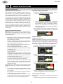 2
2
-
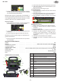 3
3
-
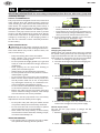 4
4
-
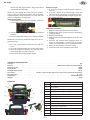 5
5
-
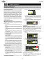 6
6
-
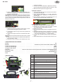 7
7
-
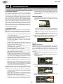 8
8
-
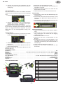 9
9
-
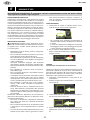 10
10
-
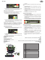 11
11
-
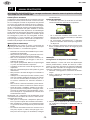 12
12
-
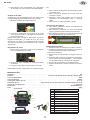 13
13
-
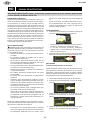 14
14
-
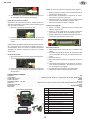 15
15
-
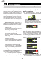 16
16
-
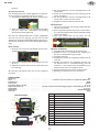 17
17
-
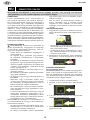 18
18
-
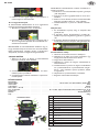 19
19
-
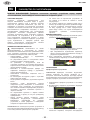 20
20
-
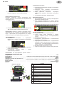 21
21
-
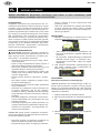 22
22
-
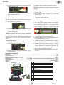 23
23
-
 24
24


en otros idiomas
- français: JBM 53687 Mode d'emploi
- italiano: JBM 53687 Guida utente
- Nederlands: JBM 53687 Gebruikershandleiding
- português: JBM 53687 Guia de usuario
- română: JBM 53687 Manualul utilizatorului
Artículos relacionados

Otros documentos
-
Schumacher SL1464 Jump Starter/Power Pack El manual del propietario
-
 Topdon V1500 Manual de usuario
-
GYS BOOSTER LITHIUM NOMAD POWER PRO TRUCK El manual del propietario
-
-
-
Beta 1498CM/12 Instrucciones de operación
-
KRAFTWERK 506.000.080 Instrucciones de operación
-
Schumacher B12.1C El manual del propietario
