wattstopper ED275GC Instrucciones de operación
- Tipo
- Instrucciones de operación

INSTALLATION
GUIDE

For more information visit www.legrand.us/cablofil
2
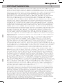
Cablofil, the inventor of wire mesh cable tray is a
revolutionary cable management system that provides
exceptional strength combined with the flexibility
to adapt easily to field requirements. Installation is
easier since wire mesh requires fewer parts and the
FAS system allows splice, bracket and accessory
connections without hardware!
Cablofil, l’inventeur du chemin de câbles en treillis
métallique, offre un système de gestion de câblage
révolutionnaire d’une robustesse exceptionnelle à laquelle
s’ajoute la souplesse d’une adaptation aisée aux exigences
d’une installation particulière. La pose est plus facile dans
la mesure où le treillis métallique demande moins de
pièces et où le système FAS permet les raccordements par
jonction de fils, sur consoles et par adaptateurs !
Cablofil, el inventor de bandejas portacables de malla de
alambre es un sistema revolucionario de gestión de cables
que proporciona una fuerza excepcional combinada con la
flexibilidad para adaptarse fácilmente a los requisitos de la
planta. ¡La instalación es más sencilla ya que la malla de
alambre requiere menos piezas y el sistema FAS permite
hacer conexiones de empalme, soporte y accesorios sin
tornillería!
CABLOFIL WIRE MESH TRAY
CHEMIN DE CÂBLES EN TREILLIS MÉTALLIQUE /
BANDEJA DE MALLA DE ALAMBRE CABLOFIL
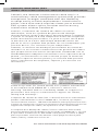
Cable Tray Label (as shown above) lists product information
in accordance with NEMA VE-1, Section 6, which lists
warning “DO NOT USE as a walkway ladder or support for
personnel. Use only as a mechanical support for cables,
tubing and raceways.”
L’étiquette du chemin de câble (voir ci-dessus) fournit les informations
produit conformément à l’article NEMA VE-1, Section 6, qui stipule
l’avertissement suivant : “NE PAS UTILISER en tant que passerelle avec
échelle ou chemin d’accès pour le personnel. Exclusivement réservé au
support mécanique de câbles, de tuyauteries et de canalisations.
La etiqueta de la bandeja de cables (como se muestra más arriba)
presenta información del producto de acuerdo con NEMA VE-1, sección
6, que indica la advertencia “NO USAR como pasillo, escalera o apoyo
para el personal. Utilícela únicamente como apoyo mecánico para
cables, tubos y conductos eléctricos.”

Pour plus de détails, visiter www.legrand.us/cablofil
Para obtener información adicional visite www.legrand.us/cablofil
3
INSTRUCTIONS / INSTRUCTIONS /
INSTRUCCIONES
FINISHES 4-5
FINITIONS /
ACABADOS
HOW TO CUT CABLE TRAY 6-7
COUPE D’UN CHEMIN DE CÂBLES /
CÓMO CORTAR BANDEJAS PORTACABLES
HOW TO SPLICE CABLE TRAY 8-9
JONCTION DE CHEMINS DE CÂBLES /
CÓMO EMPALMAR
BANDEJAS PORTACABLES
INSTALLATION EXAMPLES 10
EXEMPLES D’INSTALLATIONS /
EJEMPLOS DE INSTALACIÓN
T JUNCTIONS: RAD T 90 KIT 11
JONCTIONS EN TÉ : KIT RAD T 90 /
UNIONES EN T: JUEGO RAD T 90
T JUNCTIONS: EZ T 90 KIT 12
JONCTIONS EN TÉ : EZ T 90 KIT /
UNIONES EN T: JUEGO EZ T 90
90° BENDS: RAD T 90 KIT 13
COUDE À 90° : KIT RAD T 90 /
CODOS DE 90°: JUEGO RAD T 90
90° BENDS: EZ T 90 KIT 14
COUDE À 90° : KIT EZ T 90 /
CODOS DE 90°: JUEGO EZ T 90
Y JUNCTIONS 15
JONCTIONS EN Y / UNIONES EN Y
90° JUNCTIONS 16
JONCTIONS À 90° /
UNIONES DE 90°
SWEEPS - SWK 17
COURBES À GRAND RAYON - SWK /
CURVAS - SWK
REDUCTIONS 19
RÉTRÉCISSEMENTS /
REDUCCIONES
CHANGING LEVELS 19
CHANGEMENT DE NIVEAU /
CAMBIO DE NIVELES
BONDING AND GROUNDING 20
MISE À LA TERRE /
CONEXIONES A TIERRA
LOADING 21
CHARGE /
CARGA
SUPPORT SPACING 22-23
ESPACEMENT DES SUPPORTS /
DISTANCIA ENTRE SOPORTES
PRODUCTS / PRODUITS /
PRODUCTOS
TRAY 24
CHEMIN /
BANDEJAS
TRAY COVERS 24
COUVRE-CHEMINS
/ CUBIERTAS DE BANDEJAS
SPLICING 25
JONCTION /
EMPALMES
ACCESSORIES 25-26
ACCESSOIRES /
ACCESORIOS
WALL MOUNTINGS 26-27
MONTAGES MURAUX /
MONTAJES DE PARED
CEILING MOUNTINGS 27-28
MONTAGES AU PLAFOND /
MONTAJES DE TECHO
UNDER FLOOR MOUNTINGS 28-29
MONTAGES SOUS PLANCHER /
MONTAJES DE DEBAJO DEL PISO
OTHER MOUNTING 29-30
AUTRE MONTAGE /
OTROS MONTAJES
INDEX
SOMMAIRE /
ÍNDICE

For more information visit www.legrand.us/cablofil
4
PG
Carbon Steel
Acier au carbone
Acero al carbón
ASTM A653
Pre-Galvanized
/ Pré-galvanisée /
Pregalvanizado:
Continuous Galvanization Before Fabrication
Galvanisation continue avant fabrication
Galvanización continua antes de la fabricación
ASTM A 653
EZ
Carbon Steel
Acier au carbone
Acero al carbono
ASTM A510
Grade / Nuance / Grado 1008
Electrozinc
/ Zinguée par électrolyse /
Electrozinc
:
Electrozinc plating
Zingage parélectrolyse
Zinc electrodepositado
ASTM B 633
GC
Carbon Steel
Acier au carbone
Acero al carbono Steel
ASTM A510
Grade / Nuance / Grado 1008
Hot Dipped Galvanized
/ Galvanisée par immersion à chaud /
Galvanizado en caliente
:
After Fabrication
Après fabrication
Después de la fabricación
ASTM A 123
DC
Carbon Steel
Acier au carbone
Acero al cabón
ASTM A510
Grade / Nuance / Grado 1008
Dacromet
/ Dacromet /
Dacromet
:
Zinc and Aluminum Protection Equivalent
to Hot Dip Galvanization
Protection zinc et aluminium équivalente à la galvanisation par
immersion à chaud
Protección de zinc y aluminio equivalente a la galvanización
e caliente
ASTM F 1136
304L
Stainless Steel
Acier inoxydable
Acero inoxidable
AISI Type / Type / Tipo 304L
Stainless Steel 304L
/ Acier inoxydable 304L /
Acero inoxidable 304L
:
Cleaned and Passivated
Nettoyé et passivé
Limpio y pasivado
ASTM A 380
316L
Stainless Steel
Acier inoxydable
Acero inoxidable
AISI Type / Type / Tipo 316L
Stainless Steel 316L
/ Acier inoxydable 316L /
Acero inoxidable 316L
:
Cleaned and Passivated
Nettoy t passivé
Limpio y pasivado
ASTM A 380
BL
Carbon Steel
Acier au carbone
Acero al arbono
ASTM A510
Grade / Nuance / Grado 1008
Black Painted
/ Peinte en noir /
Pintado de negro
:
Black Powder Coated
Poudrage noir
Pintura en polvo negra
ASTM D 3451
PE
Carbon Steel
Acier au carbone
Acero la carbono
ASTM A510
Grade / Nuance / Grado 1008
Custom Painted
/ Peinte spécialement /
Pintura especial
:
Custom Color Powder Coated
Poudrage couleur spéciale
Pintura en polvo de color especial
ASTM D 3451
FINISH & STANDARD
FINITION MATIÈRE ET NORME
ACABADO DE MATERIAL Y ESTÁNDAR
SYMBOL
SYMBOLE
SÍMBOLO
MATERIAL
MATIÈRE
MATERIAL
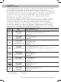
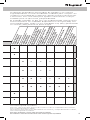
FINISHES
FINITIONS /
ACABADOS
Legrand/Cablofil wire cable tray and accessories are available
in a variety of finishes to meet any industry need, from
decorative to extreme environments. Use this chart to help you
determine the best finish for your application and its availablilty.
Standard finish is EZ, electroplated zinc. (indoor applications)
Stock finishes available include (EZ), electroplated zinc,
(316L), 316 stainless steel, (GC), Hot dipped galvanized,
(BL) Black powder coat paint.
Le chemin de câbles en treillis métallique et les accessoires Legrand/
Cablofil sont disponibles dans diverses finitions pour répondre à tous
les besoins de l’industrie en termes de décoration ou de conditions
d’utilisation difficiles. Se reporter au tableau pour déterminer plus
facilement la finition la mieux adaptée à l’application et sa disponibilité.
La finition standard est EZ, zinc argenté. (applications intérieures)
Parmi les finitions courantes disponibles figurent (EZ) zinc argenté,
(316L) acier inoxydable 316, (GC) galvanisée par immersion à chaud,
(BL) peinture noire par poudrage électrostatique.
recommended possible
recommandée possible
recomendado posible
l l

Pour plus de détails, visiter www.legrand.us/cablofil
Para obtener información adicional visite www.legrand.us/cablofil
5
PG
Carbon Steel
Acier au carbone
Acero al carbón
ASTM A653
Pre-Galvanized
/ Pré-galvanisée /
Pregalvanizado:
Continuous Galvanization Before Fabrication
Galvanisation continue avant fabrication
Galvanización continua antes de la fabricación
ASTM A 653
EZ
Carbon Steel
Acier au carbone
Acero al carbono
ASTM A510
Grade / Nuance / Grado 1008
Electrozinc
/ Zinguée par électrolyse /
Electrozinc
:
Electrozinc plating
Zingage parélectrolyse
Zinc electrodepositado
ASTM B 633
GC
Carbon Steel
Acier au carbone
Acero al carbono Steel
ASTM A510
Grade / Nuance / Grado 1008
Hot Dipped Galvanized
/ Galvanisée par immersion à chaud /
Galvanizado en caliente
:
After Fabrication
Après fabrication
Después de la fabricación
ASTM A 123
DC
Carbon Steel
Acier au carbone
Acero al cabón
ASTM A510
Grade / Nuance / Grado 1008
Dacromet
/ Dacromet /
Dacromet
:
Zinc and Aluminum Protection Equivalent
to Hot Dip Galvanization
Protection zinc et aluminium équivalente à la galvanisation par
immersion à chaud
Protección de zinc y aluminio equivalente a la galvanización
e caliente
ASTM F 1136
304L
Stainless Steel
Acier inoxydable
Acero inoxidable
AISI Type / Type / Tipo 304L
Stainless Steel 304L
/ Acier inoxydable 304L /
Acero inoxidable 304L
:
Cleaned and Passivated
Nettoyé et passivé
Limpio y pasivado
ASTM A 380
316L
Stainless Steel
Acier inoxydable
Acero inoxidable
AISI Type / Type / Tipo 316L
Stainless Steel 316L
/ Acier inoxydable 316L /
Acero inoxidable 316L
:
Cleaned and Passivated
Nettoy t passivé
Limpio y pasivado
ASTM A 380
BL
Carbon Steel
Acier au carbone
Acero al arbono
ASTM A510
Grade / Nuance / Grado 1008
Black Painted
/ Peinte en noir /
Pintado de negro
:
Black Powder Coated
Poudrage noir
Pintura en polvo negra
ASTM D 3451
PE
Carbon Steel
Acier au carbone
Acero la carbono
ASTM A510
Grade / Nuance / Grado 1008
Custom Painted
/ Peinte spécialement /
Pintura especial
:
Custom Color Powder Coated
Poudrage couleur spéciale
Pintura en polvo de color especial
ASTM D 3451
l
l
l l l l
l l l l
l l l l l l
l l l l l l
l
l
Interior installations
Installations intérieures
Instalaciones interiores
Halogen environments
Environnements halogénés
Entornos de halógeno
Exterior installations
Installations extérieures
Instalaciones exteriores
Petroleum Plants, Chemical Plants
Industrie pétrolière Industrie chimique
Refinerías de petróleo Plantas químicas
Marine/salt, Weak sulphurous
environments
Environnements de sel marin, faiblement sulfureux
Entornos marinos/salados, sulfurosos débiles
Food Production, Wash-down,
Clean rooms
Production alimentaire, Lavage à grande eau, Salles blanches
Producción de alimentos, lavado, salas de limpieza
Acidic, alkaline environments
Environnements acides, alcalins
Entornos ácidos, alcalinos
Se dispone de bandejas portacables de alambre y accesorios
Legrand/Cablofil en una variedad de acabados para cumplir con
cualquier necesidad de la industria, desde entornos decorativos
a extremos. Use esta tabla para ayudar a determinar el mejor
acabado para su aplicación y disponibilidad.
El acabado estándar es EZ, zinc electrodepositado. (aplicaciones
interiores) Entre los acabados disponibles se incluyen (EZ), zinc
electrodepositado, (316L), acero inoxidable 316, (GC), galvanizado
en caliente, (BL) pintura en polvo negra.
For a more detailed explanation of finish standards and compatibility,
visit www.legrand.us/cablofil.
Pour une explication plus détaillée des normes et de la compatibilité des finitions,
visiter www.legrand.us/cablofil.
Para obtener una explicación detallada de las normas y compatibilidad de acabado,
visite www.legrand.us/cablofil.

For more information visit www.legrand.us/cablofil
6
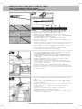
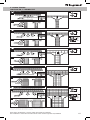
• Always use side action bolt cutters.
• Angle all cuts away from the new end.
• Cut each wire with one clean cut – eliminating
any grinding or touch-up.
• Toujours utiliser des coupe-boulons de côté.
• Effectuer toutes les coupes en biais par rapport à la
nouvelle extrémité.
• Couper chaque tige du treillis en effectuant une seule
coupe nette pour éliminer tout meulage ou retouche.
• Use siempre cortapernos de acción lateral.
• Haga todos los cortes alejándose del nuevo extremo.
• Corte cada alambre haciendo un corte limpio,
eliminando rectificaciones o retoques.
• Cut the bottom wires first, in order as shown,
from the underside of the tray.
• Rest the lower jaw of the cutters against the
cradle wire and cut at an angle away from the
new end.
• Couper d’abord les tiges inférieures, dans l’ordre
indiqué, du dessous du chemin.
• Faire reposer la lame inférieure du coupe-boulon
contre la tige berceau et couper en biais par rapport
à la nouvelle extrémité.
• Corte primero los alambres inferiores, en orden según
se muestra, desde el lado de abajo de la bandeja.
• Apoye la mordaza inferior de los cortadores contra el
alambre del asiento y corte en ángulo alejándose del
nuevo extremo.
• Cut the side wires next, starting with the top
wire.
• Make sure the finished cut is safe and ready
for installation.
• Couper ensuite les tiges latérales en commençant par
la tige supérieure.
• Veiller à ce que la coupe finie soit sûre et prête à
l’installation.
• Corte a continuación los alambres laterales,
empezando por el alambre superior.
• Asegúrese de que el corte acabado sea seguro y esté
listo para su instalación.
2
1
3
4
5
6
LENGTH
LONGUEUR
LONGITUD
WEIGHT
POIDS
PESO
INCHES
POUCES
PULGADAS
MM LBS KG/1
COUPFIL 24.8” 630 9.5 4.3 559 507
HOW TO CUT CABLOFIL CABLE TRAY
COUPE D’UN CHEMIN DE CÂBLES CABLOFIL
CÓMO CORTAR BANDEJAS PORTACABLES CABLOFIL

Pour plus de détails, visiter www.legrand.us/cablofil
Para obtener información adicional visite www.legrand.us/cablofil
7
ITEM
ARTICLE
ARTÍCULO
DESCRIPTION
DESCRIPTION
DESCRIPCIÓN
945064
Cablocut*
Cablocut*
Cablocut*
Cutter, Case, Spare Blades
Coupe-fil, coffre, lame supplémentaire
Cortador, estuche, hojas de repuesto
945065
Cablocut Blades
Lames Cablocut
Hojas Cablocut
Spare Blades
Lame supplémentaire
Hojas de repuesto
945066
Cablocut Battery*
Batterie Cablocut*
Batería Cablocut*
18 V Li-Ion Battery 1.5/A/HR
Batterie au lithium-ion de 18 V/1,5 Ah
Batería de iones de litio de 18 V/1.5 AH
945067
Cablocut Charger*
Chargeur Cablocut*
Caegador Cablocut*
120 VAC Quick Charger
Chargeur rapide de 120 VCA
Cargador rápido de 120 VCA
*Battery and Charger sold and shipped separately.
*Batterie et chargeur vendus et expédiés séparément.
*La batería y el cargador se venden y envían por separado.
HOW TO CUT CABLOFIL CABLE TRAY
COUPE D’UN CHEMIN DE CÂBLES CABLOFIL
CÓMO CORTAR BANDEJAS PORTACABLES CABLOFIL
USING A POWER CUTTER TO CUT CABLOFIL – CABLOCUT
UN OUTIL ÉLECTRIQUE CONÇU POUR COUPER LES CHEMINS DE CÂBLES CABLOFIL : CABLOCUT
EMPLEO DE CORTADORA ELÉCTRICA PARA CORTAR CABLOFIL — CABLOCUT
Cablocut reduces jobsite labor and results in a better, safer cut. Use cutting
instructions from page 6 to properly cut Cablofil tray.
Cablocut réduit la charge de travail sur le chantier et produit une coupe plus nette et plus
sécuritaire. Observer les instructions de coupe à la page 6 afin de couper correctement
les chemins de câbles Cablofil.
Cablocut reduce las horas de mano de obra y produce mejores cortes y más
seguros. Utilice las instrucciones de corte de la página 6 para cortar debidamente su
portacables Cablofil.
• Small head size permits cuts close to welds
• 300 cuts between charges
• Cuts steel or stainless wire mesh tray up to 6mm in diameter
• Multifunction illumination/battery charge indicator LED
• Uses Makita 18 V/1.5 Ah Lithium-ion battery
• Tête de petite dimension qui permet de couper près des soudures
• Autonomie de 300 coupes entre les charges
• Coupe les chemins de câbles en fils d’acier ou d’acier inoxydable
allant jusqu’à 6 mm de diamètre
• Lampe multifonction/indicateur de charge de la batterie à DEL
• Alimenté par une batterie Makita au lithium-ion de 18 V/1,5 Ah
• El pequeño tamaño de la cabeza permite cortar cerca de
las soldaduras
• 300 cortes entre cargas
• Corta portacables de mallas de acero o acero inoxidable
de hasta 6 mm de diámetro
• LED de iluminación de funciones múltiples/indicador
de carga de batería
• Usa una batería de iones de litio Makita de 18 V/1.5 Ah
SHEARING ACTION RESULTS IN CLEAN EDGE
PRODUIT UN CISAILLAGE QUI DONNE DES COUPES NETTES
LA ACCIÓN DE CIZALLADURA PRODUCE UN BORDE LIMPIO
OLD TOOLS,
ELECTRIC OR MANUAL
ANCIENS OUTILS, ÉLECTRIQUES
OU MANUELS
HERRAMIENTAS MÁS VIEJAS,
ELÉCTRICAS O MANUALES
CABLOCUT
RESULTS
CABLOCUT
RÉSULTATS
CABLOCUT
RESULTADOS
CASE KK50L
COFFRE KK50L
ESTUCHE KK50L
CHARGER LGL1*
CHARGEUR LGL1
CARGADOR LGL1
20V Quick charger
RAL1 BATTERY*
BATTERIE RAL1
BATERÍA RAL1
18 V / 1.5 Ah / Li-Ion
ACCESSORIES

For more information visit www.legrand.us/cablofil
8
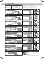
HOW TO SPLICE CABLOFIL CABLE TRAY – EDRN
JONCTION DE CHEMIN DE CÂBLES CABLOFIL - EDRN
CÓMO EMPALMAR BANDEJAS PORTACABLES CABLOFIL - EDRN
HOW TO SPLICE CABLOFIL CABLE TRAY - SWK
JONCTION DE CHEMIN DE CÂBLES CABLOFIL - SWK
CÓMO EMPALMAR BANDEJAS PORTACABLES CABLOFIL - SWK
21 3
INSTRUCTIONS / INSTRUCTIONS / INSTRUCCIONES
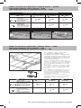
SPLICING GUIDELINES / CONSIGNES DE JONCTION / GUÍAS DE EMPALME
CF30 – CF54
CF105 – CF150
2”
8”
(50
MM)
12” (300
MM)
18”
24”
(450
600 MM)
EDRN splices needed
on side wires
Jonctions EDRN nécessaires sur
les fils de treillis latéraux
Se necesitan empalmes EDRN en
alambres laterales
2x
EDRN
2x
EDRN
2x
EDRN
EDRN splices needed
on bottom of tray
Jonctions EDRN nécessaires sur
le bas du chemin
Se necesitan empalmes EDRN en
la parte inferior de la bandeja
–
1x
EDRN
2x
EDRN
CF30 – CF54
CF105 – CF150
2” (50
MM)
4”
8”
(100
200 MM)
12”
24”
(300
600 MM)
SWK attachment sets needed
for side wires
Ensembles de fixation SWK
nécessaires pour les fils de treillis
latéraux
Conjuntos de sujeción SWK necesa-
rios para los alambres laterales
2x
SWK
2x
SWK
2x
SWK
SWK attachment sets needed
for bottom wires
Ensembles de fixation SWK
nécessaires pour le fil de treillis
inférieur
Conjuntos de sujeción SWK necesa-
rios para los alambres inferiores
–
1x
SWK
2x
SWK
• Use SWK to splice any two
sections of Cablofil tray.
• Swaged nut allows clamp to be
stationary while nut is tightened.
• Consult chart below for correct
number of SWK sets needed for
each width of tray.
• Utiliser un SWK pour joindre deux sec-
tions quelconques de chemin Cablofil.
• L’écrou estampé permet à la bride de
rester immobile pendant le serrage
de l’écrou.
• Consulter le tableau ci-dessous pour
le nombre correct d’ensembles SWK
nécessaires pour chaque largeur de
chemin.
• Use SWK para empalmar dos seccio-
nes cualquiera de bandejas Cablofil.
• La tuerca recalcada permite que la
abrazadera permanezca fija mientras
se aprieta la tuerca.
• Consulte en el cuadro de abajo el
número correcto de conjuntos SWK
necesarios para cada ancho de
bandeja.
SWK

Pour plus de détails, visiter www.legrand.us/cablofil
Para obtener información adicional visite www.legrand.us/cablofil
9
x1
x1
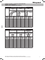
HORIZONTAL TEE / TÉ HORIZONTAL / TE HORIZONTAL
RADT90 EZT90 Y JUNCTION
JONCTIONS EN Y
UNIÓN EN Y
TRAY
WIDTH
LARGEUR
CHEMIN
ANCHO DE
LA BANDEJA
QTY.
REQUIRED
QTÉ.
NÉCESSAIRE
CANT.
REQUERIDA
CUT
INSTRUT.
INSTRUCT
COUPE
INSTRUCT.
CORTE
QTY.
REQUIRED
QTÉ.
NÉCESSAIRE
CANT.
REQUERIDA
CUT
INSTRUT.
INSTRUCT
COUPE
INSTRUCT.
CORTE
QTY.
REQUIRED
QTÉ.
NÉCESSAIRE
CANT.
REQUERIDA
CUT
INSTRUT.
INSTRUCT
COUPE
INSTRUCT.
CORTE
2” - - 1 kit p. 13 - -
4” 1 kit p. 12 1 kit p. 13 p. 16 p. 16
6” 1 kit p. 12 1 kit p. 13 p. 16 p. 16
8” 1 kit p. 12 1 kit p. 13 p. 16 p. 16
12” 1 kit p. 12 1 kit p. 13 p. 16 p. 16
18” 1 kit p. 12 1 kit p. 13 p. 16 p. 16
20” 1 kit p. 12 1 kit p. 13 - -
24” 1 kit p. 12 1 kit p. 13 - -
90 DEGREE BENDS / COUDES À 90° /
CODOS DE 90°
SWK
(SWEEP)
(COURBE GRAND RAYON)
(CURVA)
RADT90 EZT90
TRAY
WIDTH
LARGEUR
CHEMIN
ANCHO DE
LA BANDEJA
QTY.
REQUIRED
QTÉ.
NÉCESSAIRE
CANT.
REQUERIDA
CUT
INSTRUT.
INSTRUCT
COUPE
INSTRUCT.
CORTE
QTY.
REQUIRED
QTÉ.
NÉCESSAIRE
CANT.
REQUERIDA
CUT
INSTRUT.
INSTRUCT
COUPE
INSTRUCT.
CORTE
QTY.
REQUIRED
QTÉ.
NÉCESSAIRE
CANT.
REQUERIDA
CUT
INSTRUT.
INSTRUCT
COUPE
INSTRUCT.
CORTE
2” 2 p. 18 - - 1 kit p. 15
4” 2 p. 18 1 kit p. 14 1 kit p. 15
6” 4 p. 18 1 kit p. 14 1 kit p. 15
8” 4 p. 18 1 kit p. 14 1 kit p. 15
12” 6 p. 18 1 kit p. 14 1 kit p. 15
18” 8 p. 18 1 kit p. 14 1 kit p. 15
20” 9 p. 18 1 kit p. 14 1 kit p. 15
24” 11 p. 18 1 kit p. 14 1 kit p. 15
DIRECTIONAL CHANGE HARDWARE
MATÉRIEL POUR DÉVIATIONS
TORNILLERÍA DE CAMBIOS DIRECCIONALES

For more information visit www.legrand.us/cablofil
10
INSTALLATION EXAMPLES
EXEMPLES D’INSTALLATIONS / EJEMPLOS DE INSTALACIÓN
EXTERIOR
INSTALLATION
INSTALLATION EXTÉRIEURE
INSTALACIÓN EXTERIOR
FOOD PROCESSING
TRAITEMENT DES ALIMENTS
PROCESAMIENTO DE ALIMENTOS
UNDERFLOOR
INSTALLATION
INSTALLATION SOUS PLANCHER
INSTALACIÓN DEBAJO DE PISOS
INTERIOR
INSTALLATION
INSTALLATION INTÉRIEURE
INSTALACIÓN INTERIOR
INDUSTRIAL PLANT
USINE
PLANTA INDUSTRIAL

Pour plus de détails, visiter www.legrand.us/cablofil
Para obtener información adicional visite www.legrand.us/cablofil
11
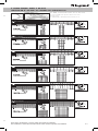
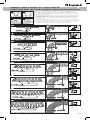
One RAD T 90 KIT will make one T Junction.
Un seul kit RAD T 90 permet d’effectuer une
jonction en té.
Un JUEGO EZ T 90 formará una unión en T.
4" (100 MM)
6" (150 MM)
8" (200 MM)
x2
x3
x4
x2
x3
x4
x2
x3
x4
x1
x1
x1
x1
x1
x1
x1
x1
x4
x1
x4
EZ BN 1/4
CE 25
RAD T 9O
X
2
x4
x1
x4
EZ BN 1/4
CE 25
RAD T 9O
X
2
x4
x1
x4
EZ BN 1/4
CE 25
RAD T 9O
X
2
x1
x1
x1
x1
x1
x1
x1
x1
1
1
1
2
2
2
x1
x1
x1
x1
x1
x1
18-20" (450-500 MM)
24" (600 MM)
12" (300 MM)
x7
x8
x7
x8
x5
x4
x1
x1
x4
x1
x4
EZ BN 1/4
CE 25
RAD T 9O
X
2
x4
x1
x4
EZ BN 1/4
CE 25
RAD T 9O
X
2
x4
x1
x4
EZ BN 1/4
CE 25
RAD T 9O
X
2
x1
x1
x1
x1
x1
x1
x1
x1
x1
x1
x1
x1
1
1
1
2
2
2
T JUNCTIONS: RAD T 90 KIT
JONCTIONS EN TÉ : KIT RAD T 90 /
UNIONES EN T: JUEGO RAD T 90

For more information visit www.legrand.us/cablofil
12
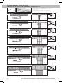
One EZ T 90 KIT will make one T Junction.
Un seul kit EZ T 90 permet d’effectuer une
jonction en té.
Un JUEGO EZ T 90 formará una unión en T.
2" (50 MM)
4" (100 MM)
6" (150 MM)
8" (200 MM)
x1
x2
x1
x2
x1
x2
x1
x2
x4
x1
x4
EZ BN 1/4
CE 25
EZ T 9O
X
2
x4
x1
x4
EZ BN 1/4
CE 25
EZ T 9O
X
2
x4
x1
x4
EZ BN 1/4
CE 25
EZ T 9O
X
2
x4
x1
x4
EZ BN 1/4
CE 25
EZ T 9O
X
2
18-20" (450-500 MM)
24" (600 MM)
12" (300 MM)
x5
x6
x5
x6
x3
x4
x4
x1
x4
EZ BN 1/4
CE 25
EZ T 9O
X
2
x4
x1
x4
EZ BN 1/4
CE 25
EZ T 9O
X
2
x4
x1
x4
EZ BN 1/4
CE 25
EZ T 9O
X
2
T JUNCTIONS: EZ T 90 KIT
JONCTIONS EN TÉ : KIT EZ T 90 /
UNIONES EN T: JUEGO EZ T 90

Pour plus de détails, visiter www.legrand.us/cablofil
Para obtener información adicional visite www.legrand.us/cablofil
13
x2
x1
x2
x2
x2
x2
x2
x2
x1
x2
x1
x2
x2
x2
x2
x2
x2
x1
x2
x1
x2
x2
x2
x2
x2
x2
x1
x3
x2
x3
x4
x2
x4
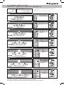
One RAD T 90 KIT will make two 90˚ Bends.
Un seul kit RAD T 90 permet d’effectuer deux
coudes à 90°.
One RAD T 90 KIT formará dos codos de 90˚.
4" (100 MM)
6" (150 MM)
8" (200 MM)
12" (300 MM)
x4
x4
EZ BN 1/4
CE 25
x1
x2
EZ BN 1/4
CE 40
X
1
x1
RAD T 9O
x4
x4
EZ BN 1/4
CE 25
x1
x2
EZ BN 1/4
CE 40
X
1
x1
RAD T 9O
x4
x4
EZ BN 1/4
CE 25
x1
x2
EZ BN 1/4
CE 40
X
1
x1
RAD T 9O
x4
x4
EZ BN 1/4
CE 25
x1
x2
EZ BN 1/4
CE 40
X
1
x1
RAD T 9O
x3
x2
x3
x4
x2
x4
x4
x4
x2
x5
x5
x2
x4
x4
x2
x5
x5
x2
18" (450 MM)
20" (500 MM)
24" (600 MM)
x4
x4
EZ BN 1/4
CE 25
x1
x2
EZ BN 1/4
CE 40
X
1
x1
RAD T 9O
x4
x4
EZ BN 1/4
CE 25
x1
x2
EZ BN 1/4
CE 40
X
1
x1
RAD T 9O
x4
x4
EZ BN 1/4
CE 25
x1
x2
EZ BN 1/4
CE 40
X
1
x1
RAD T 9O
90˚ BENDS: RAD T 90 KIT
COUDES À 90° : KIT RAD T 90 /
CODOS DE 90°: JUEGO RAD T 90

For more information visit www.legrand.us/cablofil
14
x1
x1
x1
x2
x2
x2
x2
x2
x1
x1
x1
x1
x1
x2
x2
x2
x2
x2
x1
x1
x1
x1
x1
x2
x2
x2
x2
x2
x1
x1
x1
x1
x1
x2
x2
x2
x2
x2
x1
x1
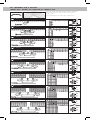
One EZ T 90 KIT will make two 90˚ Bends.
Un seul KIT EZ T 90 permet d’effectuer deux
coudes à 90°.
Un JUEGO EZ T 90 formará dos codos de 90˚.
2" (50 MM)
4" (100 MM)
6" (150 MM)
8" (200 MM)
x4
x4
EZ BN 1/4
CE 25
x1
EZ T 9O
x1
x2
EZ BN 1/4
CE 40
X
1
x4
x4
EZ BN 1/4
CE 25
x1
EZ T 9O
x1
x2
EZ BN 1/4
CE 40
X
1
x4
x4
EZ BN 1/4
CE 25
x1
EZ T 9O
x1
x2
EZ BN 1/4
CE 40
X
1
x4
x1
x4
EZ BN 1/4
CE 25
EZ T 9O
X
1
x3
x2
x3
x3
x2
x3
x3
x2
x3
x3
x2
x3
x4
x4
x2
x4
x4
x2
x4
x4
x2
x4
x4
x2
12" (300 MM)
18" (450 MM)
20" (500 MM)
24" (600 MM)
x4
x4
EZ BN 1/4
CE 25
x1
EZ T 9O
x1
x2
EZ BN 1/4
CE 40
X
1
x4
x4
EZ BN 1/4
CE 25
x1
EZ T 9O
x1
x2
EZ BN 1/4
CE 40
X
1
x4
x4
EZ BN 1/4
CE 25
x1
EZ T 9O
x1
x2
EZ BN 1/4
CE 40
X
1
x4
x4
EZ BN 1/4
CE 25
x1
EZ T 9O
x1
x2
EZ BN 1/4
CE 40
X
1
90˚ BENDS: EZ T 90 KIT
COUDES À 90° : KIT EZ T 90 /
CODOS DE 90°: JUEGO EZ T 90

Pour plus de détails, visiter www.legrand.us/cablofil
Para obtener información adicional visite www.legrand.us/cablofil
15
x1
x1
x1
x2
x1
x1
x1
x1
x2
x1
x1
x1
x3
x1
x1
x1
x1
x3
x1
x1
x1
x1
x1
x3
x1
x1
x1
x1
x3
x1
4" (100 MM)
6" (150 MM)
8" (200 MM)
1
1
1
2
2
2
x2
x1
x2
EZ BN 1/4
CE 25
ED 275*
X
3
X
3
X
1
X
2
x1
SWK
x1
SWK
x1
SWK
x1
x1
x1
x2
x1
x1
x1
x1
x2
x1
x1
x1
x1
x2
x1
x1
x1
x4
x1
x1
x1
x1
x4
x1
x1
x1
x5
x1
x1
x1
x1
x5
x1
x1
x1
12" - 20” - 24” (300 - 500 - 600 MM)
18" (450 MM)
1
1
2
2
x2
x1
x2
EZ BN 1/4
CE 25
ED 275*
X
4
X
2
X
2
*Use bolt cutters to fabricate this part from ED 275.
*Utiliser un coupe-boulon pour fabriquer cette pièce à partir d’un ED 275.
*Use bolt cutters to fabricate this part from ED 275.
x1
SWK
x1
SWK
x1
x1
x1
x2
x1
x1
x1
x1
x2
x1
Y JUNCTIONS
JONCTIONS EN Y / UNIONES EN Y

For more information visit www.legrand.us/cablofil
16
One EZ T 90 KIT will make two 90˚
Junctions.
Un seul KIT EZ T 90 permet d’effectuer deux
jonctions à angle droit.
Un JUEGO EZ T 90 formará dos uniones de 90˚.
x1
x2
x2
x3
x1
x2
x2
x3
4" (100 MM)
8" (200 MM)
6" (150 MM)
12" (300 MM)
x4
x4
EZ BN 1/4
CE 25
x1
EZ T 9O
x1
x2
EZ BN 1/4
CE 40
X
1
x4
x4
EZ BN 1/4
CE 25
x1
EZ T 9O
x1
x2
EZ BN 1/4
CE 40
X
1
x4
x4
EZ BN 1/4
CE 25
x1
EZ T 9O
x1
x2
EZ BN 1/4
CE 40
X
1
x4
x4
EZ BN 1/4
CE 25
x1
EZ T 9O
x1
x2
EZ BN 1/4
CE 40
X
1
OTHER THAN 90˚ JUNCTIONS
JONCTIONS AUTRES QU’À ANGLE DROIT /
OTRAS UNIONES QUE NO SEAN DE 90˚
x4
x5
x6
18" (450 MM)
20" (500 MM)
24" (600 MM)
x4
x4
EZ BN 1/4
CE 25
x1
EZ T 9O
x1
x2
EZ BN 1/4
CE 40
X
1
x4
x4
EZ BN 1/4
CE 25
x1
EZ T 9O
x1
x2
EZ BN 1/4
CE 40
X
1
x4
x4
EZ BN 1/4
CE 25
x1
EZ T 9O
x1
x2
EZ BN 1/4
CE 40
X
1
X
1
x1
x2
EZ BN 1/4
CE 40
90˚ JUNCTIONS
JONCTIONS À ANGLE DROIT / UNIONES DE 90˚

Pour plus de détails, visiter www.legrand.us/cablofil
Para obtener información adicional visite www.legrand.us/cablofil
17
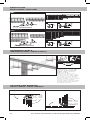
SWEEPS: SWK & EZ BN 1/4 / CE25 / ED275
COURBES À GRAND RAYON : SWK ET EZ BN 1/4/CE25/ED275 /
CURVAS: SWK Y EZ BN 1/4/CE25/ED275
*Use bolt cutters to
cut to fit.
*Utiliser des coupe-
boulons pour couper de
façon à ajuster.
*Use los cortapernos
para cortar a la medida.
x2
x3
x4
x3
x2
x3
x3
x4
x2
x3
x4
x3
4" (100 MM)
6" (150 MM)
8" (200 MM)
x2
x1
x2
EZ BN 1/4
CE 25
ED 275*
X
3
x2
x1
x2
EZ BN 1/4
CE 25
ED 275*
X
3
x2
x1
x2
EZ BN 1/4
CE 25
ED 275*
X
2
x1
SWK
x2
x3
x4
x3
2" (50 MM)
x4
x1
x4
EZ BN 1/4
CE 25
ED 275*
X
3
7.5"
190 MM
5.5"
140 MM
R
12.6"
320 MM
8.7"
220 MM
R
17.7"
450 MM
11.8"
300 MM
R
17.7"
450 MM
9.8"
250 MM
R
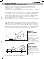
Sweeps can be formed easily on site by cutting some of
the side and bottom wires. Use the SWK method to secure
desired curve. Always place bolt heads to inside of tray to
prevent frayed wires.
Il est possible de former aisément des courbes à grand rayon sur place
en coupant certains des fils de treillis latéraux et inférieurs. Utiliser
la méthode SWK pour obtenir la courbe souhaitée. Toujours placer la
tête des boulons à l’intérieur du chemin pour empêcher un éraillage
des fils de treillis.
Las curvas pueden formarse fácilmente en la obra cortando algunos de
los alambres laterales e inferiores. Use el método SWK para asegurar la
curva deseada. Coloque siempre las cabezas de los pernos en el interior
de la bandeja para impedir que se desgasten los alambres.
1
A
2
B
12" (300 MM)
20" (500 MM)
18" (450 MM)
24" (600 MM)
x2
x1
x2
EZ BN 1/4
CE 25
ED 275*
x2
x1
x2
EZ BN 1/4
CE 25
ED 275*
X
4
X
9
X
6
X
11
X
2
X
2
x1
SWK
x1
SWK
x1
SWK
x1
SWK
x6
x11
x9
x8
x6
x11
x9
x8
x6
x11
x9
x8
x6
x11
x9
x8
27.6"
700 MM
15.8"
400 MM
R
37.4"
950 MM
19.7"
500 MM
R
42.5"
1080 MM
22.8"
580 MM
R
52.8"
1340 MM
29.1"
740 MM
R

For more information visit www.legrand.us/cablofil
18
x1
x1 x1
x1
x1
x1
x2
x1
x1 x1
x1
x1
x1
x2
4" (100 MM)
8" (200 MM)
x1
SWK
X
1
X
1
x2
x1
x2
EZ BN 1/4
CE 25
ED 275*
X
1
x2
x1
x2
EZ BN 1/4
CE 25
ED 275*
x1
SWK
X
1
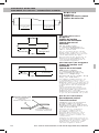
To avoid obstructions or
change levels, cut the side
wires as shown and bend
Cablofil cable tray to the
angles needed.
Pour éviter les obstacles ou
changer de niveau, couper les fils
de treillis latéraux comme indiqué
et recourber le chemin de câbles
Cablofil aux angles nécessaires.
Para evitar obstrucciones o cambiar
de nivel, corte los alambres
laterales según se muestra y doble
la bandeja portacables Cablofil a
los ángulos necesarios.
R = 2.5" 64 MM
R = 2.5" 64 MM
R = 7.5" 190 MM
R = 7.5" 190 MM
R = 13" 320 MM
R = 13" 320 MM
R = 18" 445 MM
R = 18" 445 MM
CUTTING AND BENDING
COUPE ET CINTRAGE /
CORTES Y DOBLADOS
CHANGING LEVELS
CHANGEMENT DE NIVEAU /
CAMBIO DE NIVELES
REDUCTIONS
RÉTRÉCISSEMENTS /
REDUCCIONES

Pour plus de détails, visiter www.legrand.us/cablofil
Para obtener información adicional visite www.legrand.us/cablofil
19
Per NEC 392, the national electrical code section for cable tray, all
cable tray systems must be properly BONDED, per section 259.96.
To meet this requirement, Cablofil recommends that ULclassified
splices are used to joins sections and that the cable tray be bonded
to building steel or the facility grounding system every 50’-60’.
By bonding the tray every 50’-60’, the tray will maintain a low
potential to ground which reduces EMI and provides a continuous
path for stray currents. Steel trapeze type hangers clamped
securely to building steel usually provide a solid bond. Cablofil
standard splices (SWK, EDRN, EZBN, EZT90, RADT90) are designed
to have less than 1 milliohm of resistance between connections
and provide bonding between sections. These splices have been
tested by UL as part of the cable tray grounding system. Painted
Cablofil wire mesh tray requires the outer mask of the conductive
surface be removed at each end of the tray prior to installing the
(SWK) splice. This (SWK) splice provides a UL Classified Bonding
continuity between painted tray sections. All cable tray needs to be
electrically continuous per NEC 250.96. Standard Cablofil splices
provide continuity per 250.96. utting and removal of cable tray
sections still allow continuity per 250.96 and only affects the rare
use of cable tray as the EGC. Use of cable tray as an EGC is rare
since UL requires all multiconductor cables to contain an integral
EGC and single conductor cables are only used in a few industrial
applications.
Conformément à la spécification NEC 392, la section du Code national de
l’électricité qui traite des chemins de câbles, tous ceux-ci doivent être
correctement MIS À LA TERRE comme indiqué dans la section 259.96.
Afin de respecter cette spécification, Cablofil recommande d’utiliser des
jonctions agréées UL pour joindre des sections et de mettre le chemin de
câbles à la terre en le reliant à l’armature métallique du bâtiment ou à
l’installation de mise à la terre des locaux tous les 15 à 18 m (50 à 60 pi). Si
on procède ainsi, le chemin maintient un faible potentiel à la terre qui réduit
la perturbation électromagnétique et offre une voie continue aux courants
vagabonds. Des tirants en acier de type trapézoïdal fixés solidement à
l’armature en acier du bâtiment assurent généralement une mise à la
terre sûre. Les jonctions standard de Cablofil (SWK, EDRN, EZBN, EZT90,
RADT90) sont conçues pour avoir une résistance inférieure à 1 milliohm
entre connexions et assurent une liaison électrique entre les sections.Ces
jonctions ont été testées par les UL en tant qu’éléments de l’installation
de mise à la terre du chemin de câbles. Les chemins de câbles en treillis
métallique peints de Cablofil exigent la dépose du masque extérieur de la
surface conductrice à chaque extrémité du chemin avant la mise en place
de la jonction (SWK). Cette jonction (SWK) assure une continuité de masse
agréée par les UL entre les sections d’un chemin peint. Tous les chemins
de câbles doivent assurer une continuité électrique conformément à la
spécification NEC 250.96. Les jonctions standard Cablofil assurent une telle
continuité. La coupe et le retrait de sections de chemin de câble n’éliminent
pas la continuité exigée par la spécification 250.96 et n’affectent que la
rare utilisation d’un chemin de câbles comme PE. Une telle utilisation est
rare dans la mesure où les UL exigent que tous les câbles multipolaires
comportent un PE intégré et où les câbles unipolaires ne sont employés
que dans quelques applications industrielles.
Según NEC 392, la sección de código de eléctrico nacional para bandejas
portacables, todos los sistemas de portacables deben estar debidamente
CONECTADOS A TIERRA, según la sección 259.96. Para cumplir con este
requisito, Cablofil recomienda usar empalmes clasificados UL para unir
secciones y que la bandeja portacables esté conectada a tierra al acero
del edificio o al sistema de conexión a tierra de la instalación cada 50’-
60’. Al conectar a tierra cada 50’-60’ de bandeja, la bandeja mantendrá un
potencial bajo a tierra lo que reduce las interferencias electromagnéticas
y proporciona una vía continua para corrientes parásitas. Los soportes
colgantes de acero tipo trapecio sujetos firmemente al acero del edificio
proporciona una conexión a tierra firme. Los empalmes estándar Cablofil
BONDING AND GROUNDING
MISE À LA TERRE /
CONEXIONES A TIERRA

For more information visit www.legrand.us/cablofil
20
(SWK, EDRN, EZBN, EZT90, RADT90) están diseñados para tener una
resistencia menor que 1 miliohmio entre conexiones y proporcionan una
conexión a tierra entre secciones. UL ha probado estos empalmes como
parte del sistema de conexión a tierra de la bandeja portacables. La
bandeja de malla de cable pintada Cablofil requiere retirar el recubrimiento
exterior de la superficie conductora en cada extremo de la bandeja
antes de instalar el empalme (SWK). Este empalme (SWK) proporciona
una continuidad de conexión a tierra clasificada por UL entre secciones
de bandejas pintadas. Todas las bandejas portacables necesitan ser
eléctricamente continuas según NEC 250.96. Los empalmes Cablofil
estándar proporcionan continuidad según 250.96. El corte y la retirada
de secciones de bandejas portacables sigue permitiendo la continuidad
según 250.96 y sólo afecta al uso poco común de bandejas de cable como
EGC. El uso de bandejas portacables como EGC es poco común, ya que
UL requiere cables multiconductores para contener un EGC integral y los
cables monoconductores sólo deben usarse en una pocas aplicaciones
industriales.
Cablofil has been tested to UL, CSA, NEMA VE1 and IEC
standards. Cablofil wire mesh tray and supports are designed
to support any cable load allowed by the NEC when supports
are spaced on 8' spans. Only the heaviest cables (750 kcmil
multiconductor power or larger) may require shorter spans.
For specific loading go to the interactive load table on
www.legrand.us/cablofil and choose your exact cable for
detailed cable capacity and span requirements.
Le chemin Cablofil a été testé aux normes UL, CSA, NEMA VE1 et IEC.
Le chemin en treillis métallique Cablofil et ses supports sont conçus
pour accepter toute charge de câbles autorisée par le Code national de
l’électricité tant que les supports sont espacés de 2,40 m (8 pi). Seuls
les câbles les plus lourds (multipolaires d’alimentation de 750 kcmil ou
plus gros) peuvent exiger un espacement inférieur. Pour toute charge
particulière, consulter le tableau des charges interactif à www.cablofil.com
et choisir le câble exact pour les spécifications détaillées de capacité en
câbles et d’espacement des supports.
Se han hecho pruebas de Cablofil según las normas UL, CSA, NEMA VE1
e IEC. La bandeja de malla de alambre y los soportes de Cablofil están
diseñados para soportar cualquier carga de cable permitida por el NEC
cuando los soportes estén separados a intervalos de 8’. Solamente los
cables más gruesos (de alimentación de conductores múltiples de 750 kcmil
o mayores) pueden requerir separaciones más cortas. Para obtener cargas
específicas vaya a la tabla de cargas interactivas en www.cablofil.com y
escoja su cable exacto para obtener requisitos detallados de capacidad de
cables y separaciones.
Cablofil comes in 118" lengths and straight sections are designed
for 6'-8' support spacing; (building joists or purlins are typically on
6'-7' spacing).
Cablofil has developed the following diagrams as a general
guideline for supporting Field Fabricated Wire Mesh Tray. These
guidelines will provide assistance in estimating and locating
supports for the most common wire mesh tray installations.
Supports are required as some of the side wires have been cut and
the load capacity has been reduced. In actual installation, shallow
and narrow trays may not require as many supports just as deep
and wide trays may require additional supports. The installer
should keep in mind that unique requirements arise in the field
and practical solutions are often simple.
LOADING
CHARGE /
CARGA
SUPPORT SPACING
ESPACEMENT DES SUPPORTS /
SEPARACIÓN DE SOPORTES

Pour plus de détails, visiter www.legrand.us/cablofil
Para obtener información adicional visite www.legrand.us/cablofil
21
Le chemin Cablofil est offert en sections de 295 cm (118 po) et les sections
droites sont conçues pour un espacement de 1,80 à 2,40 m (6 à 8 pi) des
supports (les poutrelles ou pannes de bâtiments sont généralement
espacées de 1,80 à 2,10 m [6 à 7 pi]).
Cablofil a créé les schémas suivants destinés à servir de directives générales
de soutien d’un chemin de câble en treillis métallique confectionné sur
place. Ces directives aideront à estimer le nombre et l’espacement des
supports pour les installations les plus courantes de chemins de câbles en
treillis métallique.Il est nécessaire de prévoir les supports en tenant compte
de la coupe de certains des fils latéraux de treillis et de la réduction de la
charge admissible. Dans une installation réelle, les chemins peu profonds et
étroits peuvent ne pas exiger autant de supports, de même que les chemins
profonds et larges peuvent en exiger plus. L’installateur ne doit pas oublier
que des exigences particulières apparaissent chez le client et que les
solutions pratiques sont souvent simples.
Cablofil viene en secciones de 118” y las secciones rectas están diseñadas
para una separación entre soportes de 6’-8’; (las viguetas o correas del
edificio están separadas normalmente 6’-7’).
Cablofil ha desarrollado los diagramas siguientes como guía general para
sujetar la bandeja de malla de alambre fabricada en planta. Estas guías
serán de ayuda para estimar y ubicar los soportes para las instalaciones
de bandejas de malla de alambre más comunes, Se necesitan soportes, ya
que se han cortado algunos de los alambres laterales y se ha reducido la
capacidad de carga. En la instalación real, es posible que las bandejas poco
profundas y estrechas no requieran tantos soportes tan profundos y las
bandejas anchas pueden requerir soportes adicionales. El instalador deben
tener en cuenta que los requisitos exclusivos surgen en la planta y las
soluciones prácticas a menudo son sencillas.
SUPPORT SPACING
ESPACEMENT DES SUPPORTS /
SEPARACIÓN DE SOPORTES
600 mm MAX
(2'-O')
1/2
600 mm MAX
(2'-O')
A
A - 45° - 120°
Horizontal Sweep
Support
Soutien des courbes
horizontales à grand rayon
Soporte de curva horizontal
Center support not
required on trays less
than 12" wide and sweeps
less than 45 degrees.
Un support central n’est pas
nécessaire sur les chemins
de moins de 30 cm (12 po) de
large ni sur les courbes de
moins de 45 degrés.
No se necesita un soporte
central en bandejas de menos
de 12” de ancho y en curvas
de menos de 45 grados.
Horizontal Y
Support
Support de jonction
horizontale en Y
Soporte Y horizontal
Center support not
required on trays less
than 12" wide.
Un support central n’est pas
nécessaire sur les chemins
de moins de 30 cm (12 po) de
large.
No se requiere un soporte
central en bandejas de menos
de 12” de ancho. on trays less
than 12” wide.
600 mm MAX
(2'-O')
600 mm MAX
(2'-O')
600 mm MAX
(2'-O')
45°
27.5°

For more information visit www.legrand.us/cablofil
22
600 mm MAX
(2'-O')
600 mm MAX
(2'-O')
2'-0'
(610mm)
2'-0'
(610mm)
2'-0'
(610mm)
W
2'-0'
(610mm)
Horizontal Cross
Support
Support de jonction
transversale horizontale
Soporte transversal
horizontal
On 24' wide items,
recommended distance
is 1 ft. 6 in. (457mm) from
splice connection.
Sur les chemins de 60 cm (24
po) de large, la distance recom-
mandée par rapport à la jonction
est de 457 mm (1 pi 6 po).
En artículos de 24’ de ancho, la
distancia recomendada es de
1 pie 6 pulg (457mm) desde la
conexión del empalme.
Reduction
Support
Support de rétrécissement
Soporte de reducción
Horizontal Tee Support
Support de jonction en té
horizontale
Soporte de te horizontal
Additional support
recommended at back
of tee (shown) or directly
under tee, diagonally
positioned, for 4" and 6" deep
trays, 18" and wider.
Un support supplémentaire est
recommandé à l’arrière du té
(illustré) ou juste sous celui-ci, en
diagonale, pour les chemins de 10
et 15 cm (4 et 6 po) de profondeur
et d’au moins 45 cm (18 po) de
large.
Se recomienda un soporte
adicional en la parte trasera de
la te (mostrada) o directamente
debajo de la te, colocado
diagonalmente, para bandejas de
4” y 6” de profundidad, 18” y más.
Vertical Transition
Raccordement vertical
Transición vertical
Support vertical transition
at top support location.
Distances of 3 ft. and larger
should be supported at each
end as illustrated.
Soutenir un raccordement
vertical à l’emplacement
de support supérieur. Les
portions d’au moins 91 cm (3
pi) doivent être soutenues à
chaque extrémité comme sur
l’illustration.
Soporte la transición vertical en
la ubicación del soporte superior.
Las distancias de 3 pies y más
deben estar sujetas en cada
extremo según se indica.
SUPPORT SPACING
ESPACEMENT DES SUPPORTS /
SEPARACIÓN DE SOPORTES
TOP
SUPPORT
VERTICAL
TRANSITION
TOP SUPPORT
SUPPORT SUPÉRIEUR
SOPORTE SUPERIOR
VERTICAL TRANSITION
RACCORDEMENT
VERTICAL
TRANSICIÓN VERTICAL

Pour plus de détails, visiter www.legrand.us/cablofil
Para obtener información adicional visite www.legrand.us/cablofil
23
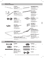
CTXF 35
TELEX RAIL
COVER
COUVRE-RAIL
TELEX
CUBIERTA DE
CARRIL TELEX
UC 35
TELEX RAIL
STANDOFF SUPPORT
SUPPORT À MONTAGE
VERTICAL DE RAIL
TELEX
SOPORTE DE
SEPARACIÓN DE
CARRIL TELEX
CVN
CABLOFIL
TRAY COVER
COUVRE-CHEMIN
CABLOFIL
CUBIERTA
DE BANDEJA
CABLOFIL
COT 54
DIVIDER STRIP
BANDE DE
JONCTION
TIRA DIVISORA
COT 105/COT 150
DIVIDER STRIP
BANDE DE JONCTION
TIRA DIVISORA
CLIP FO2
CABLOFIL COVER CLIP
CLIP DE COUVRE-CHEMIN CABLOFIL
PRESILLA DE CUBIERTA CABLOFIL
COT F
FLEXIBLE DIVIDER
JONCTION FLEXIBLE
DIVISOR FLEXIBLE
COT J
DIVIDER COUPLER
DISPOSITIF DE
JONCTION
ACOPLADOR DIVISOR
INSERT
TRAY INSERT
INSERT POUR
CHEMIN
INSERTO DE
BANDEJA
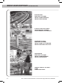
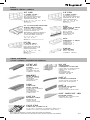
TRAY
CHEMIN DE CÂBLES /
BANDEJA
TRAY COVERS
COUVRE-CHEMINS /
CUBIERTAS DE BANDEJAS
CF 54
2” DEEP TRAY
CHEMIN DE 2
PO
DE PROFONDEUR
BANDEJA DE 2” DE
PROFUNDIDAD
2”, 4”, 6”, 8”, 12”, 18”,
20”, & 24”
WIDE/DE LARGE/
DE ANCHO
CF 150
6” DEEP TRAY
CHEMIN DE 6
PO
DE PROFONDEUR
BANDEJA DE 6” DE
PROFUNDIDAD
12”, 18”, 20”, & 24”
WIDE/DE LARGE/
DE ANCHO
CF 105
4” DEEP TRAY
CHEMIN DE 4
PO
DE PROFONDEUR
BANDEJA DE 4” DE
PROFUNDIDAD
4”, 6”, 8”, 12”, 18”, 20”, & 24”
WIDE/DE LARGE/
DE ANCHO
UL CLASSIFIED PAINTED
WIRE CABLE TRAY
CHEMIN DE CÂBLES
EN FILS PEINT AVEC
CONFORMITÉ UL
BANDEJA PORTACABLES
DE ALAMBRE PINTADO
CLASIFICADA POR UL
2”, 4”, 6”, 8”, 12”,
18”, 20”, & 24”
WIDE/DE LARGE/
DE ANCHO
CFG
CABLOFIL G-TRAY
AND G-MINI
CABLFIL G-TRAY
ET G-MINI
BANDEJA G
Y G-MINI DE
CABLOFIL
CFL
CABLOFIL L TRAY
CHEMIN
CABLOFIL L
BANDEJA
CABLOFIL L
TXF35
TELEX RAIL
RAIL TELEX
CARRIL TELEX

For more information visit www.legrand.us/cablofil
24
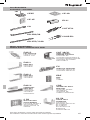
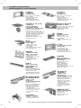
EZBN
1/4”
EZFW
1/4”, 3/8”, 1/2”
EZHN
1/4”, 3/8”, 1/2”
THRD
1/4”, 3/8”, 1/2”
ACCESSORIES
ACCESSOIRES /
ACCESORIOS
SPLICING
JONCTION /
EMPALMES
SWK
EZCN
1/4”, 3/8”, 1/2”
TRP
THREADE ROD
PROTECTOR
PROTECTION DE
TIGE FILETÉE
PROTECTOR DE
BARRAS
ROSCADO
EDRN
FAST SPLICE
JONCTION
RAPIDE
EMPALME RÁPIDO
EDRNTOOL
MOUNTING TOOL
OUTIL DE
MONTAGE
HERRAMIENTA
DE MONTAJE
EDRSKIT
TRAY
REDUCTION KIT
KIT DE
RÉTRÉCISSEMENT
DE CHEMIN
JUEGO DE REDUC-
CIÓNDE BANDEJAS
ED 275
UNIVERSAL
SPLICE BAR
BARRE DE
JONCTION
UNIVERSELLE
BARRA DE
EMPALME
UNIVERSAL
EAC
ELEVATION
CHANGE HINGE
ARTICULATION
DE CHANGEMENT
DE PENTE
ARTICULACIÓN
DE CAMBIO DE
ELEVACIÓN
EZT 90 KIT
90˚ AND TEE
BEND KIT
KIT DE TÉ / COURBE
JUEGO DE CODOS
DE 90° Y TES
SWK
SPLICE
WASHER KIT
JEU DE
RONDELLES DE
JONCTION
JUEGO DE
ARANDELAS DE
EMPALME
CE 40
SQUARE SPLICE
WASHER
RONDELLE
CARRÉE DE
JONCTION
ARANDELA
DE EMPALME
CUADRADA
RAD T 90 KIT
5½” RADIUS
TEE 90˚ KIT
KIT DE TÉ, 5½ PO
DE RAYON
JUEGO DE TES DE
90˚ DE 5½” DE
RADIO
RAD T 9012 KIT
12” RADIUS TEE 90˚ KIT
KIT DE TÉ, 12 PO DE RAYON
JUEGO DE TES DE 90° DE 12”
DE RADIO
CE 25
SPLICE WASHER
RONDELLE
CARRÉE DE
JONCTION
ARANDELA
DE EMPALME
CUADRADA
CE 35
CLAMPING
WASHER
RONDELLE DE
SERRAGE
ARANDELA DE
FIJACIÓN

Pour plus de détails, visiter www.legrand.us/cablofil
Para obtener información adicional visite www.legrand.us/cablofil
25
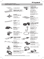
ACCESSORIES
ACCESSOIRES /
ACCESORIOS
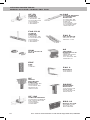
WALL MOUNTINGS
MONTAGE MURAUX /
MONTAJES EN LA PARED
FAS P
FAS PROFILE
PROFILÉ FAS
PERFIL FAS
FAS L
BRACKET
SUPPORT
SOPORTE
FAS U
UNIVERSAL
BRACKET
SUPPORT
UNIVERSEL
SOPORTE
UNIVERSAL
FV
VERTICAL BRACKET
SUPPORT VERTICAL
SOPORTE VERTICAL
FAS C
BRACKET
SUPPORT
SOPORTE
EDF
RAIL
RAIL
CARRIL
CRP
UNIVERSAL WALL
BRACKET
SUPPORT MURAL
UNIVERSEL
SOPORTE DE
PARED UNIVERSAL
CA
CUTYFIL
ED 275/1100
CE 40
CE 35
ECLI
COUPFIL
ED 250/90
CE25
CAT 30/41
SNAP-IN WALL
HANGER SUPPORT
SUPPORT DE
SUSPENSION MURALE À
NCLENCHEMENT RAPIDE
SOPORTE DE PARED
ENCAJABLE
C 50
WALL MOUNT
ATTACHMENT
FIXATION MURALE
ACCESORIO DE
MONTAJE EN LA
PARED
UC 50
CABLE TRAY
STANDOFF
SUPPORT À
MONTAGE VERTICAL
DE CHEMIN
DE CÂBLES
ESPACIADO DE
BANDEJA
PORTACABLES

For more information visit www.legrand.us/cablofil
26
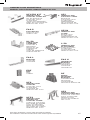
CEILING MOUNTINGS
MONTAGES AU PLAFOND /
MONTAJES EN EL TECHO
EDF
RAIL
RAIL
CARRIL
DF
ANGLE
MOUNTING
BRACKET
CORNIÈRE DE
MONTAGE
SOPORTE DE
MONTAJE
ANGULAR
PREDF
MOUNTING
BRACKET
SUPPORT DE
MONTAGE
SOPORTE DE
MONTAJE
ERD 10
BRACE PLATE
ENTRETOISE
PLACA DE
REFUERZO
SF 50
CENTER
HANGER
SUPPORT
CENTRAL DE
SUSPENSION
SOPORTE
COLGANTE
CENTRAL
FAS PCH
CENTER
HANGER
SUPPORT
CENTRAL DE
SUSPENSION
SOPORTE
COLGANTE
CENTRAL
FAS C
BRACKET
SUPPORT
SOPORTE
SON
SLIP-ON LOCK
NUT®
SF 100
CENTER HANGER
SUPPORT CENTRAL
DE SUSPENSION
SOPORTE
COLGANTE
CENTRAL
SAS
SINGLE HANGER
SUSPENSION
BRACKET
SUPPORT DE
SUSPENSION
SIMPLE
SOPORTE
COLGANTE DE
SUSPENSIÓN
INDIVIDUAL
FAS P
FAS PROFILE
PROFILÉ FAS
PERFIL FAS
AS
TRAPEZE
HANGING CLIP
TIRANT
TRAPÉZOÏDAL
PRESILLA
COLGANTE DE
TRAPECIO

Pour plus de détails, visiter www.legrand.us/cablofil
Para obtener información adicional visite www.legrand.us/cablofil
27
SAS
SINGLE HANGER
SUSPENSION
BRACKET
SUPPORT DE
SUSPENSION
SIMPLE
SOPORTE
COLGANTE DE
SUSPENSIÓN
INDIVIDUAL
FAS P
FAS PROFILE
PROFILÉ FAS
PERFIL FAS
AS
TRAPEZE
HANGING CLIP
TIRANT
TRAPÉZOÏDAL
PRESILLA
COLGANTE DE
TRAPECIO
UNDERFLOOR MOUNTINGS
MONTAGES SOUS PLANCHER /
MONTAJES DEBAJO DEL PISO
UFC
UNDER FLOOR
SUPPORT CLAMP
BRIDE DE
SUPPORT SOUS
PLANCHER
ABRAZADERA
DE SOPORTE DE
DEBAJO DEL PISO
EDF
RAIL
RAIL
CARRIL
UFS
UNDER FLOOR
SUPPORT
SUPPORT SOUS
PLANCHER
SOPORTE DE
DEBAJO DEL PISO
UFCN
UNDER FLOOR
CLAMP
BRIDE SOUS
PLANCHER
ABRAZADERA DE
DEBAJO DEL PISO
DF
ANGLE
MOUNTING
BRACKET
CORNIÈRE DE
MONTAGE
SOPORTE DE
MONTAJE ANGULAR
UFFS
UNDER FLOOR
FIBERGLASS
SUPPORT STAND
CONSOLE SUPPORT
EN FIBRE DE VERRE
SOUS PLANCHER
BASE DE SOPORTE
DE FIBRA DE VIDRIO
DEBAJO DEL PISO
UFS
UNDER FLOOR
SUPPORT BRACKET
CONSOLE SUPPORT
SOUS PLANCHER
MÉNSULA DE
APOYO DE DEBAJO
DEL PISO
FAS P
FAS PROFILE
PROFILÉ FAS
PERFIL FAS
UC 50
CABLE TRAY
STANDOFF
SUPPORT À
MONTAGE
VERTICAL DE
CHEMIN DE
CÂBLES
SOFF DE BANDEJA
PORTACABLES
C 50
UNDER FLOOR
ATTACHMENT
FIXATION SOUS
PLANCHER
SUJECIÓN POR
DEBAJO DEL PISO
FAS L
BRACKET
SUPPORT
SOPORTE
FAS U
UNIVERSAL
BRACKET
SUPPORT
UNIVERSEL
SOPORTE
UNIVERSAL
UFC550 KIT
UNDER FLOOR
SUPPORT CLAMP KIT
KIT DE BRIDE DE
SUPPORT SOUS
PLANCHER
JUEGO DE ABRAZAD-
ERAS DE SOPORTE DE
DEBAJO DEL PISO

For more information visit www.legrand.us/cablofil
28
OTHER MOUNTINGS
AUTRES MONTAGES /
OTROS MONTAJES
FASCLM KIT
BEAM CLAMP
BRIDE DE FIXATION
SUR POUTRE
ABRAZADERA
DE VIGA
CE40CC & CH
CONDUIT
ATTACHMENT
FITTINGS AND
CONDUIT CLAMP KIT
ACCESSOIRES DE
FIXATION POUR ET
KIT DE COLLIER POUR
TUBE PROTECTEUR
JUEGO DE ACCESORIOS
DE SUJECIÓN DE
CONDUCTOS Y
ABRAZADERAS DE
CONDUCTOS
SBDA
CONDUIT AND
BOX SUPPORT
SUPPORT DE
CONDUIT ET DE
COFFRET
SOPORTE DE
CONDUCTOS Y
CAJAS
EZBC
BEAM CLAMP
BRIDE DE
FIXATION SUR
POUTRE
ABRAZADERA DE
VIGA
ETC
TRAY BEAM
SUPPORT
SUPPORT DE
CHEMIN SUR
POUTRE
SOPORTE DE VIGA
DE BANDEJA
CC KIT
CONDUIT
CLAMP KIT
KIT DE COLLIERS
DE TUBE
PROTECTEUR
JUEGO DE
ABRAZADERAS DE
CONDUCTOS
CM50I
INDUSTRIAL
BOX MOUNTING
BRACKET
SUPPORT DE
MONTAGE
DE COFFRET
INDUSTRIEL
SOPORTE DE
MONTAJE DE CAJA
INDUSTRIAL
CCLMP
CABLE CLAMP
SERRE-CÂBLE
SUJETACABLES
C 50
ELECTRICAL BOX
SUPPORT
SUPPORT DE
COFFRET DE
BRANCHEMENT
SOPORTE DE
CAJA ELÉCTRICA
PLEXO3KIT/
PLEXO4KIT
TWIST ON
PLASTIC
JUNCTION BOXES
BOÎTES DE
RACCORDEMENT
EN PLASTIQUE
VERROUILLÉES
PAR ROTATION
CAJAS DE
CONEXIONES DE
PLÁSTICO CON
FIJACIÓN POR
GIRO
TC4KIT/
TC5KIT
TWIST ON
METALLIC
JUNCTION BOXES
BOÎTES DE
RACCORDEMENT
MÉTALLIQUES
VERROUILLÉES
PAR ROTATION
CAJAS DE
CONEXIONES
METÁLICAS DE
FIJACIÓN POR
GIRO
HB 2
WALL/FLOOR
TERMINATION
BRACKET
SUPPORT DE
RACCORDEMENT
MUR/PLANCHER
SOPORTE DE
TERMINACIONES
DE PARED/PISO
AB225 KIT
ANGLE BRACKET
ÉQUERRE DE
FIXATION
SOPORTE EN
ÁNGULO
C50CC
CONDUIT
CLAMP KIT
KIT DE COLLIERS
DE TUBE
PROTECTEUR
JUEGO DE
ABRAZADERAS
DE CONDUCTOS

Pour plus de détails, visiter www.legrand.us/cablofil
Para obtener información adicional visite www.legrand.us/cablofil
29
OTHER MOUNTINGS
AUTRES MONTAGES /
OTROS MONTAJES
SZMCKIT
SEISMIC
BRACING KIT
KIT DE LIGATURE
ANTIVIBRATILE
JUEGO DE
TIRANTES
SÍSMICOS
YCKIT
YOKE CLAMP KIT
KIT D’ÉTRIER DE
FIXATION
JUEGO DE
SUJECIÓN DE
HORQUILLAS
SZMCSWAG
HAND SWAGER
PINCE À
ESTAMPER
RECALCADOR
MANUAL
GNDCL
GROUNDING LUG
COSSE DE MISE À
LA TERRE
OREJA DE CON-
EXIÓN A TIERRA
RB112KIT
RACK BRACKET KIT
KIT SUPPORT
POUR BAIE
JUEGO DE
SOPORTES DE
ESTANTES
FS 41
FASTRUT
CONNECTOR
BARRETTE FASTRUT
CONECTOR
FASTRUT
SZMCCUTR
CABLE CUTTER
PINCE COUPE-
CÂBLE
CORTACABLES
GNDSB
GROUNDING LUG
COSSE DE MISE À
LA TERRE
OREJA DE
CONEXIÓN A TIERRA
FLAMESTOPPER™
DROP OUT KIT
CABLE DROP OUT
DESCENTE DE CÂBLE
BAJAA DE CABLE
CABLEXIT
WMC2LA
WIRE MESH
CABLE TRAY-TO-
LADDER CLAMP
BRIDE DE
FIXATION
DE CHEMIN
DE CÂBLES
EN TREILLIS
MÉTALLIQUE À
ÉCHELLE
ABRAZADERA
DE BANDEJA A
ESCALERILLA DE
ALAMBRES DE
MALLA
FAS ROLLER
CLIP
CABLE LABEL
CLIP
ATTACHE
ÉTIQUETTE DE
CÂBLE
PRESILLA DE
ETIQUETAS DE
CABLES
MFM
METALLIC
MULTIFIX PLATE
PLAQUE
MÉTALLIQUE
MULTIFIX
PLACA METÁLICA
DE FIJACIÓN
MÚLTIPLE
FAS ROLLER HD
HEAVY DUTY
GUIDE-CÂBLE À
ROULEAUX RENFORCÉ
SERVICIO PESADO
EZVC
VELCRO ROLL
ROULEAU
VELCRO
ROLLO DE
VELCRO
EZJB 5/16
J-BOLT
BOULON EN J
PERNO EN J
CABLO SNAP
CABLE BUNDLER
COLLIER DE
FAISCEAU DE
CÂBLES
EMPAQUETADOR
DE CABLES

www.legrand.us/cablofil
Phone 800-658-4641
618-566-3230
Fax 618-566-4978
8319 State Route 4
Mascoutah, IL USA 62258
EZ•331•07•17
-
 1
1
-
 2
2
-
 3
3
-
 4
4
-
 5
5
-
 6
6
-
 7
7
-
 8
8
-
 9
9
-
 10
10
-
 11
11
-
 12
12
-
 13
13
-
 14
14
-
 15
15
-
 16
16
-
 17
17
-
 18
18
-
 19
19
-
 20
20
-
 21
21
-
 22
22
-
 23
23
-
 24
24
-
 25
25
-
 26
26
-
 27
27
-
 28
28
-
 29
29
-
 30
30


wattstopper ED275GC Instrucciones de operación
- Tipo
- Instrucciones de operación
en otros idiomas
- français: wattstopper ED275GC Mode d'emploi
Otros documentos
-
RIDGID 14228 Manual de usuario
-
Master Lock 8252DAT Instrucciones de operación
-
Hubbell Wiring Device-Kellems PD2004 Guía de instalación
-
-
Samoa 559501 Instructions Manual
-
Yamaha YSP-5600 El manual del propietario
-
 Elektra Beckum mig mag 302 ep Operating Instructions Manual
-
-
Sencor SWK1574BR-NAB1 Guía del usuario
-
dBTechnologies VIO S118R El manual del propietario
