Peavey Unity 2002-12 RQ Manual de usuario
- Categoría
- Ecualizadores de audio
- Tipo
- Manual de usuario


Intended to alert the user to the presence of uninsulated "dangerous voltage" within the product's enclosure
that may be of sufficient magnitude to constitute a risk of electric shock to persons.
Intended to alert the user of the presence of important operating and maintenance (servicing) instructions in the
literature accompanying the product.
CAUTION: Risk of electrical shock – DO NOT OPEN!
CAUTION: To reduce the risk of electric shock, do not remove cover. No user serviceable parts inside. Refer servicing to
qualified service personnel.
WARNING: To prevent electrical shock or fire hazard, do not expose this appliance to rain or moisture. Before using this
appliance, read the operating guide for further warnings.
Este símbolo tiene el propósito de alertar al usuario de la presencia de "(voltaje) peligroso" que no tiene
aislamiento dentro de la caja del producto que puede tener una magnitud suficiente como para constituir riesgo de
corrientazo.
Este símbolo tiene el propósito de alertar al usario de la presencia de instruccones importantes sobre la operación
y mantenimiento en la literatura que viene con el producto.
PRECAUCION: Riesgo de corrientazo – No abra.
PRECAUCION: Para disminuír el riesgo de corrientazo, no abra la cubierta. No hay piezas adentro que el usario pueda
reparar. Deje todo mantenimiento a los técnicos calificados.
ADVERTENCIA: Para evitar corrientazos o peligro de incendio, no deje expuesto a la lluvia o humedad este aparato
Antes de usar este aparato, lea más advertencias en la guía de operación.
Ce symbole est utilisé pur indiquer à l'utilisateur la présence à l'intérieur de ce produit de tension non-isolée
dangereuse pouvant être d'intensité suffisante pour constituer un risque de choc électrique.
Ce symbole est utilisé pour indiquer à l'utilisateur qu'il ou qu'elle trouvera d'importantes instructions sur
l'utilisation et l'entretien (service) de l'appareil dans la littérature accompagnant le produit.
ATTENTION: Risques de choc électrique – NE PAS OUVRIR!
ATTENTION: Afin de réduire le risque de choc électrique, ne pas enlever le couvercle. Il ne se trouve à l'intérieur
aucune pièce pouvant être réparée par l'utilisateur. Confier l'entretien à un personnel qualifié.
AVERTISSEMENT: Afin de prévenir les risques de décharge électrique ou de feu, n'exposez pas cet appareil à la pluie
ou à l'humidité. Avant d'utiliser cet appareil, lisez les avertissements supplémentaires situés dans le guide.
Dieses Symbol soll den Anwender vor unisolierten gefährlichen Spannungen innerhalb des Gehäuses warnen, die
von Ausreichender Stärke sind, um einen elektrischen Schlag verursachen zu können.
Dieses Symbol soll den Benutzer auf wichtige Instruktionen in der Bedienungsanleitung aufmerksam machen, die
Handhabung und Wartung des Produkts betreffen.
VORSICHT: Risiko – Elektrischer Schlag! Nicht öffnen!
VORSICHT: Um das Risiko eines elektrischen Schlages zu vermeiden, nicht die Abdeckung enfernen. Es befinden sich
keine Teile darin, die vom Anwender repariert werden könnten. Reparaturen nur von qualifiziertem Fachpersonal
durchführen lassen.
ACHTUNG: Um einen elektrischen Schlag oder Feuergefahr zu vermeiden, sollte dieses Gerät nicht dem Regen oder
Feuchtigkeit ausgesetzt werden. Vor Inbetriebnahme unbedingt die Bedienungsanleitung lesen.
2

3
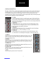
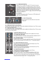
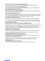
GENERAL DESCRIPTION:
The Unity™ 2002-12 RQ is a twelve input compact mixer that can be used in sound reinforcement or
recording applications. It has been engineered for maximum headroom and minimum noise, with a
10 dB headroom improvement over other designs. Quality low-noise precision parts are used
throughout the mixer. Meters on the main and the monitor outputs greatly help in checking the signal
going to the power amplifiers or tape recording inputs.
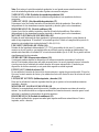
1. GAIN:
Varies the input gain to allow for a wide dynamic range. It affects both the line
and mic inputs. Proper adjustment of the input gain will maximize the signal-to-
noise ratio. If the channel clip LED lights, the level is set too high and should be
reduced until it never lights.
2. HIGH EQ:
A shelving type of active tone control that varies the treble frequency levels
+/-15 dB at 12 kHz. It is designed to remove noise or to add brilliance to the
signal, depending on the quality of the source.
3. MID EQ:
A bandpass (peak/notch) type of active tone control that varies the midrange
frequency levels +/-15 dB at a frequency of 750 Hz.
4. LOW EQ:
A shelving type of active tone control that varies the bass frequency levels
+/-15 dB at 80 Hz. It will add depth to thin signals, or clean up muddy ones.
5. MON A:
Adjusts the level of the channel signal that is added to the Monitor A mix. The
control is post-EQ and pre-fader, allowing channel fader adjustment without
affecting the Monitor A mix.
6. MON B:
Adjusts the level of the channel signal that is added to the Monitor A mix. The
control is post-EQ and pre-fader, allowing channel fader adjustment without
affecting the Monitor B mix.
7. EFFECTS A:
Adjusts the level of the channel signal that is added to the Effects A mix. It is
post-fader, designed for use as an effects send.
8. EFFECTS B:
Adjusts the level of the channel signal that is added to the Effects B mix. It is
post-fader, designed for use as an effects send.
9. PAN:
Sets the channel’s position in the L-R stereo field
8
9
5
6
7
2
3
4
1
ENGLISH

4
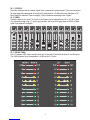
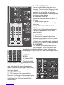
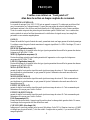
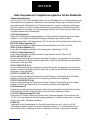
10. CLIP LED:
Normally indicates that the channel signal level is nearing the overload point. This circuit monitors
the input gain and equalization for overload. It illuminates at +19 dBu and warns that gain or EQ
boost should be reduced. There is roughly 2 dB of headroom remaining when it lights.
11. FADER:
Channel output level control. The level of the channel can be adjusted from off to +10 dB of gain.
The optimum setting is the “0” (unity gain) position, but even at full gain there is 26 dBu of head-
room (from nominal) available.
12. LED METERS:
Four 12-segment LED arrays monitor the levels of the main L/R and the Monitor A and B outputs.
The 0 dB reference level corresponds to +0 dBu at the 1/4" jacks.
1212
11
10

5
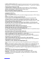
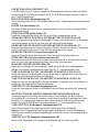
13. PHANTOM POWER:
Applies 48 VDC voltage to the input XLR connectors to power
microphones that require it. If phantom power is used, do not con-
nect unbalanced dynamic microphones or other devices to the XLR
inputs that cannot handle this voltage. (Some wireless receivers may
be damaged; consult their manuals.) The channel line input jacks
(#36) are not connected to the 48 V supply, and are safe for all inputs
(balanced or unbalanced).
14. POWER:
The mixer’s main power switch. The power-on LED indicator will
light when the unit is powered.
15. EFFECTS MASTER:
Sets the output level of the effects mix sent to the
output jack.
16. STEREO RETURN TO MONITOR A:
Sets the level of the Stereo Return signal (effects) that is added to the Monitor A mix. This is a mono
mix of the left and right signals.
17. STEREO RETURN TO MONITOR B:
Sets the level of the Stereo Return signal (effects) that is added to the Monitor B mix. This is a mono
mix of the left and right signals.
18. STEREO RETURN TO L/R:
Sets the level of the Return signal (effects) that is added to the L/R mix.
19. STEREO RETURN PAN:
Determines the balance of the Stereo Return signal that is added to the L/R
mix. If the signal is mono, it sets the left-right position.
20. MONITOR FADER:
Sets the overall level of the monitor signal that is sent to the monitor output
jack. The optimum setting for this control is the “0” (unity gain) position.
21. TAPE TO MONITOR A LEVEL:
Adjusts the level of the tape signal supplied to the Monitor A mix. This
control is independent of the tape L/R level.
22. TAPE TO MONITOR B LEVEL:
Adjusts the level of the tape signal supplied to the Monitor B mix. This
control is independent of the tape L/R level.
23. TAPE TO L/R LEVEL:
Adjusts the level of the tape signal supplied to the L/R mix.
24. MASTER LEFT/RIGHT FADERS:
Master L/R level controls. Since the tape and headphone/control room
outputs come from this mix, they will also be affected by its adjustment.
The output levels are monitored by the left and right meters. The optimum
setting for this these controls is the “0” (unity gain) position.
13
14
15
16
17
18
19
20

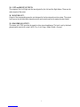
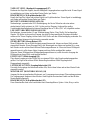
25. TAPE OUTPUT JACKS:
Provides a signal to feed a stereo tape deck or
other input. This signal is the L/R signal with the
level set by the Tape output control. The Tape
input signal is also included, and can cause
feedback if the tape input level is turned up when
recording on a single machine.
26. TAPE INPUT JACKS:
Receives the input from a stereo tape deck or a
CD player.
27. TAPE OUTPUT LEVEL:
Sets the level of the L/R signal sent to the Tape
output jacks.
28. HEADPHONE/CONTROL ROOM
LEVEL:
Adjusts the level of the headphone and outputs.
The signal is independent of the L/R master
faders (pre-fader).
29. MIC INPUT:
XLR balanced low impedance channel input
optimized for a microphone or other low imped-
ance source. Pin 2 is the positive input. Because
of the wide range of gain adjustment, signal levels
up to 21 dBu ( 8.9 VRMS) can be accommodated.
30. LINE INPUT:
1/4" balanced (TRS) high impedance input for
high-level signals. The tip is the positive input,
which should also be used for unbalanced inputs. This input is con-
nected through a 10 dB pad to the MIC input. The two inputs cannot
be used simultaneously.
31. RETURN
INPUTS:
1/4" balanced (TRS)
high impedance input
for high level signals.
These are designed for effect returns, but can be used
for additional stereo inputs. The tip is the positive
input, which should also be used for unbalanced
inputs. The Left/Mono input supplies signal to both
the left and right inputs if there is no input connected
to the right input jack.
32. AUX EFFECT OUT:
1/4" TRS Output jack of the corresponding Aux
Effect mix. It can be used to feed an external monitor
system or effects unit. The level is set by the indi-
vidual channel Aux Effects send and the Effects
Master controls. 6
21
25
26
27
28
24
23
22
30
29
32
33
35
31
34

33. LEFT and RIGHT OUTPUTS:
The outputs of the Left-Right mix that are adjusted by the Left and the Right faders. These are the
main outputs of the mixer.
34. MONITOR OUT:
Output of the corresponding monitor mix designed to feed an external monitor system. The output
levels are set by the individual channel monitor send controls and by the master monitor faders.
35. HEADPHONE OUTPUT:
This stereo jack (TRS) provides the signal to drive stereo headphones. The level is set by the head-
phone/control room level control (# 34). Tip = Left; Ring = Right; Shield = Ground.
7

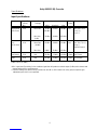
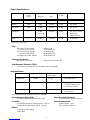
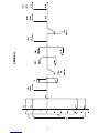
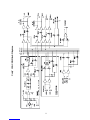
Unity 2002-12 RQ Console
Specifications:
Input Specifications:
Functions Input Z Input Gain Input Levels Bal/ Connector
(ohms) Settings Unbal
Min Min** Nominal* Max
Microphone 2.2K Max Gain -76 dBu -56 dBu -34 dBu Bal XLR Pin 1 Gnd
(150 ohms) (56 dBu) Pin 2 (+),
Pin 3 (-)
Min Gain -20 dBu -10 dBu +22 dBu
(0 dB)
Line 10 K Max Gain -64 dBu -44 dBu -22 dBu Bal 1/4" TRS; Tip (+),
(10 K ohms) (44 dB) Ring (-),
Sleeve Ground
Min Gain -8 dBu 12 dBu +32 dBu
Aux Return 22 K N/A -33 dBu -13 dBu +10 dBu Unbal 1/4" Phone
Tape 22 K N/A -23 dBu -18 dBu +10 dBu Unbal RCA Phone
0 dBu = 0.775 V (RMS)
**Min. input level (Sensitivity) is the smallest signal that will produce nominal output (0 dBu) with channel and
master faders set for maximum gain.
* Nominal settings are defined as all controls set at 0 dB (or 50% rotation for rotary pots) except the gain
adjustment pot, which is as specified.
8

9
Output Specifications:
Function Minimum Output Level Bal/ Connector
Load Z Unbal
(ohms) Nominal Max
Main L/R 600 0 dBu +22 dBu Unbal 1/4" Phone
Monitor 600 0 dBu +22 dBu Unbal 1/4" Phone
Aux Send 600 0 dBu +22 dBu Unbal 1/4" Phone
Headphone 8 0 dBu +22 dBu Unbal 1/4" TRS: Tip Left,
(no load) Ring Right,
Sleeve Ground
Tape 1 K 0 dBu +21 dBu Unbal RCA Phone
0 dBu = 0.775V (RMS)
Gain: Mic Input Gain Adj. Range: 0 dB to 56 dB
Mic Input to L/R Output: 76 dB (Max Gain)
Line Input Gain Adj. Range: -10 dB to 46 dB
Line Input to L/R Output: 66 dB (Max Gain)
Aux Return to L/R Bal. Output: 33 dB (Max Gain)
Frequency Response:
Mic Input to L-R Output: 20 Hz to 20 kHz +0 dB/-1 dB
Total Harmonic Distortion (THD):
<0.02% 20 Hz to 20 kHz Mic to L-R output: (10 Hz-80 kHz BW)
Output Residual Noise S/N Ratio Test Conditions
Ref: 0 dBu
Master L/R -94 dBu 94 dB All Faders Down
-82 dBu 82 dB Master Fader Nominal,
Channel Faders Down,
All Channels Muted
-81 dBu 81 dB All Controls Nominal,
Mic Gain Min.
(Hum and Noise Measurements: 22 Hz to 22 kHz BW)
Equivalent Input Noise (EIN): Signal/Overload Indicators:
-127 dBu (Input terminated with 150 ohms) Red LED lights 2 dB below clipping
Crosstalk: Power Requirements:
>60 dB Adjacent Input Channels (20 Hz - 20 kHz) DOM: 120 VAC 60 Hz
>60 dB Left to Right Outputs (20 Hz - 20 kHz) EXP: 230 VAC 50/60 Hz
Meters:
12-segment, peak reading
(0 dB= dBu)
Hum and Noise:


12
ESPAÑOL
Consulte los diagramas del panel
delantero en la sección de inglés de este manual.
DESCRIPCIÓN GENERAL:
La consola Unity 2002-12 RQ es un mezclador compacto de doce entradas que puede ser
utilizado en aplicaciones de grabación o donde es necesario reforzar el sonido. Ha sido diseñada para
ofrecer mínimo nivel de ruido y máxima amplitud de señal con una mejora de 10 dB en el nivel
admisible con respecto a otros diseños. La consola utiliza componentes de precisión con bajo nivel
de ruido. Los medidores de las salidas principales y de monitor resultan útiles para vigilar las señales
enviadas a los amplificadores de potencia y a las entradas de grabadores.
GAIN (Ganancia) (1)
Varía la ganancia del paso de entrada del canal para permitir una gama dinámica amplia. El ajuste
apropiado de la ganancia de entrada maximizará la relación entre señal y ruido. El indicador LED de
recorte por sobrecarga (10) ayudará a ajustar este nivel.
HIGH EQ (Ecualizador de agudos) (2)
Es un control activo de tono de nivelación que varía la gama de frecuencias altas en ±15 dB
a 12 kHz.
MID EQ (Ecualizador de medios) (3)
Es un control activo de tono de pico/ranura capaz de ±15 dB de refuerzo o corte a 750 Hz.
LOW EQ (Ecualizador de graves) (4)
Es un control activo de tono de nivelación que varía la gama de frecuencias bajas en ±15 dB
a 80 Hz.
MON A (5)
Ajusta el nivel de la señal de canal que se agrega a la mezcla de monitor A. El control es posterior al
ecualizador y anterior al atenuador, lo que permite ajustar la atenuación del canal sin afectar la
mezcla de monitor A.
MON B (6)
Ajusta el nivel de la señal de canal que se agrega a la mezcla de monitor B. El control es posterior al
ecualizador y anterior al atenuador, lo que permite ajustar la atenuación del canal sin afectar la
mezcla de monitor B.
EFFECTS A (EFECTOS A) (7)
Ajusta el nivel de la señal de canal que se agrega a la mezcla de efectos A. El control es posterior al
ecualizador y se utiliza para envío de efectos.
EFFECTS B (EFECTOS B) (8)
Ajusta el nivel de la señal de canal que se agrega a la mezcla de efectos B. El control es posterior al
ecualizador y se utiliza para envío de efectos.
PAN (Balance panorámico) (9)
Asigna el canal a cualquier posición en el campo estereofónico izquierdo-derecho. Para una
operación monaural, el canal debe asignarse a la mezcla izquierda o derecha.
CLIP LED (Indicador LED de recorte por sobrecarga) (10)
Indica que el canal está cerca del punto de recorte. Se enciende a -19 dBV aproximadamente y
señala que la ganancia de entrada (7) debe reducirse. En este punto hay 2 dBV de espacio superior
aproximadamente.

FADER (ATENUADOR) (11)
Control de nivel de salida del canal. El nivel del canal puede regularse entre apagado y +10 dB de
ganancia. La configuración óptima para este control es la posición “0” (ganancia unitaria) pero, aun
con ganancia máxima, la tolerancia del máximo nivel de señal es de 26 dBu (con respecto al valor
nominal).
LED METERS (MEDIDORES CON INDICADORES LED) (12)
Cuatro matrices de indicadores LED de 12 segmentos que monitorean los niveles de las salidas
principales izquierda y derecha y los niveles de las salidas de monitor A y monitor B. El nivel de
referencia de 0 dB corresponde a +0 dBu en los enchufes hembra de 1/4".
PHANTOM POWER (Refuerzo de potencia) (13)
Oprímelo para obtener un refuerzo de potencia de 48 V de micrófono a todas las entradas con
enchufes XLR.
POWER (Encendido) (14)
Oprímelo hacia el indicador LED para encender. El indicador LED se encenderá cuando la corriente
esté encendida.
EFFECTS MASTER (Control maestro de efectos) (15)
Ajusta el nivel global de la mezcla de efectos enviada al enchufe de salida de efectos.
STEREO RETURN TO MONITOR A (RETORNO ESTEREOFÓNICO A MONITOR A) (16)
Configura el nivel de la señal de retorno estereofónica (efectos) que se agrega a la mezcla de monitor
A. Es una mezcla monofónica de las señales de los canales izquierdo y derecho.
STEREO RETURN TO MONITOR B (RETORNO ESTEREOFÓNICO A MONITOR B) (17)
Configura el nivel de la señal de retorno estereofónica (efectos) que se agrega a la mezcla de monitor
B. Es una mezcla monofónica de las señales de los canales izquierdo y derecho.
STEREO RETURN LEVEL (NIVEL DE REGRESO ESTEREOFÓNICO) (18)
Ajusta el nivel del regreso estereofónico que se agrega a la mezcla izquierda-derecha.
STEREO RETURN PAN (Balance panorámico del regreso estereofónico) (19)
Determina el balance del regreso estereofónico a la mezcla izquierda-derecha. Si la señal de regreso
es nonoaural, éste control fija la posición izquierda o derecha.
MONITOR FADER (ATENUADORES DE MONITOR) (20)
Configura el nivel general de las señales de monitor que se envían a los enchufes hembra de salida
de monitor. La configuración óptima para estos controles es la posición “0” (ganancia unitaria).
TAPE TO MONITOR A LEVEL (NIVEL DE CINTA A MONITOR A) (21)
.Ajusta el nivel de la señal de cinta provista a la mezcla de monitor A. Este control es independiente
del nivel de los canales izquierdo y derecho de la cinta.
TAPE TO MONITOR B LEVEL (NIVEL DE CINTA A MONITOR B) (22)
Ajusta el nivel de la señal de cinta provista a la mezcla de monitor B. Este control es independiente
del nivel de los canales izquierdo y derecho de la cinta.
TAPE INPUT LEVEL (Nivel de entrada de grabación) (23)
Ajusta el nivel estereofónico de la señal de grabación agregada a la mezcla izquierda-derecha.
MASTER LEFT/RIGHT FADERS (ATENUADORES MAESTROS DE CANALES
IZQUIERDO Y DERECHO) (24)
Controles maestros de nivel de los canales izquierdo y derecho. Como las salidas de la unidad de
cinta y las salidas para auriculares/sala de control provienen de esta mezcla, también son afectadas
por este control. Los niveles de salida se monitorean mediante los medidores izquierdo y derecho. La
configuración óptima de estos controles es la posición “0” (ganancia unitaria).
TAPE OUTPUT JACKS (Enchufes de salida de grabación) (25)
Proporcionan la señal estereofónica a las entradas izquierda y derecha de una grabadora
estereofónica.
13

Nota: Esto incluye la señal de entrada de grabación, la cual puede causar retroalimentación si el
nivel de entrada de grabación es elevado al grabar con una sola máquina.
TAPE INPUT JACKS (Enchufes de entrada de grabación) (26)
Reciben la entrada estereofónica de la salida de una grabadora o un reproductor de discos
compactos.
TAPE OUT LEVEL (Nivel de salida de grabación) (27)
Determina el nivel de la señal enviada a los enchufes de salida de grabación. Esta señal es
independiente de los atenuadores maestros izquierdo y derecho (previa a los atenuadores).
HEADPHONE LEVEL (Nivel de audífonos) (28)
Ajusta el nivel de las señales izquierda y derecha del enchufe de audífonos. Esta señal es
independiente de los atenuadores maestros izquierdo y derecho (previa a los atenuadores).
MIC INPUT (ENTRADA DE MICRÓFONO) (29)
Entrada de canal balanceada de baja impedancia, optimizada para micrófonos u otras fuentes de
señal de baja impedancia. El terminal 2 es la entrada positiva. Debido a la amplitud del ajuste de la
ganancia, esta entrada tolera niveles de hasta 21 dBu (8,9 Vef).
LINE INPUT (ENTRADA DE LÍNEA) (30)
Entrada de alta impedancia balanceada de 1/4" (TRS) para señales de alto nivel. La punta del
conector es el polo positivo, que también debe ser utilizado para las entradas no balanceadas. Esta
entrada está conectada a la entrada MIC a través de un atenuador fijo de 10 dB. No es posible utilizar
simultáneamente las dos entradas.
STEREO RETURN (Regreso estereofónico) (31)
A este punto pueden regresar los dispositivos de efectos monaurales conectados a la salida de
efectos. Esta entrada proporciona una señal monaural tanto a la mezcla izquierda como a la derecha
si no hay una clavija conectada al enchufe derecho del regreso estereofónico. Cuando hay un
dispositivo de efectos conectado, a este punto debe regresar su salida izquierda.
EFFECTS OUT (Salida de efectos) (32)
Es una salida de la mezcla de efectos a los efectos externos o equipo de proceso de señal. El nivel se
fija con el control maestro de efectos y las señales de efectos del control de nivel de efectos del canal
de entrada.
LEFT/RIGHT OUTPUTS (Salidas izquierda y derecha) (33)
Estas son las salidas de la mezcla izquierda-derecha que se ajustan con los atenuadores maestros
izquierdo y derecho.
MONITOR OUT (SALIDA DE MONITOR) (34)
Salida de la correspondiente mezcla de monitor, diseñada para alimentar un sistema de monitor
externo. Los niveles de salida se configuran mediante los controles de envío a monitor para el canal
individual y mediante los atenuadores de monitor maestros.
HEADPHONE JACK (Enchufe de audífonos) (35)
Este enchufe estereofónico proporciona señal para impulsar audífonos estereofónicos. Punta =
izquierdo; anillo = derecho.
14

FRANÇAIS
Veuillez-vous référer au "front panel art"
situé dans la section en langue anglaise de ce manuel.
DESCRIPTION GÉNÉRALE :
La console de mixage Unity 2002-12 RQ est un appareil compact à 12 entrées qui peut être utilisé
pour la sonorisation ou l’enregistrement. Conçue pour une marge de sécurité maximale et un
ronflement minimal, elle offre un seuil de distorsion de 10 dB supérieur à celui d’autres modèles.
Toute la console comporte des pièces de précision haute qualité à faible bruit. Les vu-mètres des
sorties générale et retour facilitent énormément la vérification du signal envoyé aux amplis de
puissance ou aux entrées magnétophone.
GAIN (1)
Permet de modifier le gain d’entrée du canal, permettant ainsi une large gamme d’entrée dynamique.
Un réglage correct du gain d’entrée maximise le rapport signal/bruit. La DEL d’écrêtage (32) sert à
régler ce rapport.
HIGH EQ (Egalisation haute) (2)
Bouton de réglage de la tonalité active de type à pente permettant de modifier la gamme des hautes
fréquences de ±15 dB à 12 kHz.
MID EQ (Egalisation moyenne) (3)
Bouton de réglage pointe/coupe-bande permettant d’augmenter ou de couper les fréquences
moyennes de ± 15 dB à 75 Hz.
LOW EQ (Egalisation basse) (4)
Bouton de réglage de la tonalité active de type à pente permettant de modifier la gamme des basses
fréquences de ± 15 dB à 80 Hz.
MON A (RETOUR A) (5)
permet de régler le niveau du signal de canal ajouté au mixage du retour A. Cette commande est
post-égaliseur et pré-atténuateur, ce qui permet d’ajuster l’atténuation du canal sans affecter le
mixage de retour A.
MON B (RETOUR B) ( 6)
permet de régler le niveau du signal de canal ajouté au mixage du retour B. Cette commande est
post-égaliseur et pré-atténuateur, ce qui permet d’ajuster l’atténuation du canal sans affecter le
mixage de retour B.
EFFECT (EFFETS A) (7)
permet de régler le niveau du signal de canal ajouté au mixage de retour A. Cette commande post-
atténuateur est conçue pour l’envoi d’effets.
EFFECTS B (EFFETS B) (8)
permet de régler le niveau du signal de canal ajouté au mixage de retour B. Cette commande post-
atténuateur est conçue pour l’envoi d’effets.
PAN (Panoramique) (9)
Permet d’affecter au canal n’importe quelle position dans le champ stéréo gauche-droite. En mono,
le mélange droite ou gauche doit être affecté au canal.
CLIP LED (DEL d’écrêtage) (10)
Indique que le canal est presque arrivé au seuil d’écrêtage. Cette DEL s’illumine à environ +19 dBV
et indique que le gain d’entrée (7) doit être réduit. Lorsque cela se produit, il y a environ 6 dBV de
marge disponible. 15

FADER (ATTÉNUATEUR) (11) Commande de niveau de sortie de canal. Le gain du canal peut
être ajusté de 0 à +10 dB. Bien que le réglage optimal soit la position « 0 » (gain unité), la marge de
sécurité (au gain nominal) est de 26 dBu.
LED METERS (VU-MÈTRES À DEL) (12) Ces quatre rangées de 12 DEL permettent de
contrôler le niveau des sorties principales gauche et droite et des retours A et B. Le niveau de
référence 0 dB correspond à +0 dBu aux jacks de 6,3 mm (1/4 po.).
PHANTOM POWER (Puissance fantôme) (13)
Enfoncer ce bouton pour activer la puissance fantôme de 48 volts du microphone dans tous les
connecteurs d’entrée XLR.
POWER (Interrupteur) (14)
Mettre l’interrupteur sur la position DEL pour mettre le mélangeur sous tension. La DEL s’illumine
alors.
EFFECTS MASTER (Contrôle principal d’effets) (15)
Permet de régler le niveau de mélange des effets acheminé vers le jack de sortie des effets.
STEREI RETURN TO MONITOR A (RÉINJECTION STÉRÉO AU RETOUR A) (16)
permet de régler le niveau du signal de retour stéréo (effets) ajouté au mixage de retour A. Il s’agit
d’un mixage mono des signaux gauche et droit.
STEREO RETURN TO MONITOR B (RÉINJECTION STÉRÉO AU RETOUR B) (17)
Permet de régler le niveau du signal de retour stéréo (effets) ajouté au mixage de retour B. Il s’agit
d’un mixage mono des signaux gauche et droit.
STEREO RETURN LEVEL (Niveau de renvoi stéréo) (18)
Permet de régler le niveau du retour stéréo ajouté au mélange gauche-droite.
STEREO RETURN PAN (Renvoi stéréo panoramique) (19)
Fixe l’équilibre du signal stéréo renvoyé dans le mélange gauche-droite. Si le signal stéréo renvoyé
est mono, la position est soit droite soit gauche.
MONITOR FADER (ATTÉNUATIONS RETOURS) (20)
Permettent de régler le niveau général des signaux de retours A et B envoyés aux jacks de sortie des
retours. Le réglage optimal de ces commandes est « 0 » (gain unité).
TAPE TO MONITOR A LEVEL (NIVEAU MAGNÉTO À RETOUR A) (21)
Permet de régler le niveau du signal magnéto envoyé au mixage de retour A. Cette commande est
indépendante du niveau magnétophone G/D.
TAPE TO MONITOR B LEVEL (NIVEAU MAGNÉTO À RETOUR B) (22)
Permet de régler le niveau du signal magnéto envoyé au mixage de retour B. Cette commande est
indépendante du niveau magnétophone G/D.
TAPE INPUT LEVEL (Niveau d’entrée magnétophone) (23)
Permet de régler le niveau du signal en provenance du magnétophone ajouté au mélange gauche-
droite.
MASTER LEFT/RIGHT FADERS (ATTÉNUATIONS GÉNÉRALES GAUCHE/DROITE) (24)
Commandes de niveau général G/D. Étant donné que les signaux de sortie magnétophone et
écouteurs/régie proviennent de ce mixage, ils sont également affectés par son réglage. Les niveaux de
sortie sont contrôlés par les vu-mètres droit et gauche. Le réglage optimal de ces commandes est « 0 »
(gain unité).
TAPE OUTPUT JACKS (Jacks de sortie magnétophone) (25)
Fournissent un signal stéréo à l’entrée gauche et droite du magnétophone stéréo.
Remarque : Ce signal stéréo inclut le signal d’entrée du magnétophone, ce qui peut, durant
l’enregistrement avec un seul magnétophone, provoquer une rétroaction si le niveau d’entrée
magnétophone est élevé.
16

TAPE INPUT JACKS (Jacks d’entrée magnétophone) (26)
Reçoivent une entrée stéréo à partir de la sortie d’un magnétophone ou d’un lecteur de CD.
TAPE OUT LEVEL (Niveau de sortie magnétophone) (27)
Fixe le niveau du signal envoyé aux jacks de sortie magnétophone. Ce signal est indépendant des
faders principaux gauche et droite (pré-fader).
HEADPHONE LEVEL (Niveau du casque) (28)
Permet de régler les signaux gauche et droite envoyés au jack du casque. Ce signal est indépendant
des faders principaux gauche et droite (pré-fader).
MIC INPUT (ENTRÉE MICRO) (29)
Jack d’entrée XLR symétrique de basse impédance, optimisée pour le branchement d’un microphone
ou autre source de basse impédance. La broche 2 est l’entrée positive. La vaste plage du réglage de
gain permet d’utiliser des niveaux de signal allant jusqu’à 21 dBu (8,9 V RMS).
LINE INPUT (ENTRÉE LIGNE) (30)
Jack d’entrée de 6,3 mm (1/4 po.) symétrique (TRS) de haute impédance pour signaux de haut
niveau. La pointe est l’entrée positive et doit également être utilisée pour les signaux asymétriques.
Cette entrée est reliée à l’entrée MICRO via un atténuateur de 10 dB. Les deux entrées ne peuvent
pas être utilisées simultanément.
STEREO RETURN, LEFT/MONO (Retour stéréo, gauche/mono) (31)
Les périphériques d’effets mono connectés à la sortie d’effets peuvent être renvoyés à ce point. Cette
entrée fournit un signal mono au mélangeur droite et gauche lorsqu’aucune fiche n’est connectée au
jack de retour stéréo droite. Lorsqu’un périphérique stéréo est raccordé, sa sortie droite doit être
connectée en ce point. Lorsque un périphérique d’effets stéréo est connecté à la sortie d’effets, sa
sortie droite doit être renvoyée à ce point.
EFFECTS OUT (Sortie d’effets) (32)
Sortie du mélangeur d’effets vers les effets extérieurs ou le matériel de traitement des signaux. Le
niveau de sortie est déterminé par le contrôle principal d’effets, et les signaux d’effets par les
boutons de réglage de niveau d’effet d’entrée des canaux.
LEFT/RIGHT OUTPUTS (Sorties gauche/droite) (33)
Sorties gauche/droite du mélangeur après leur réglage par les faders généraux gauche et droite.
MONITOR OUT (SORTIE RETOUR) (34)
Sortie du mixage retour correspondant, conçue pour alimenter un système de retour externe. Les
niveaux de sortie sont réglés par les commandes individuelles de canal d’envoi retour et
d’atténuation générale.
HEADPHONE JACK (Jack de casque) (35)
Ce jack stéréo fournit un signal au casque stéréo. Embout = gauche. Anneau = droite.
17

DEUTSCH
Siehe Diagramm der Frontplatte im englischen Teil des Handbuchs.
Allgemeine Beschreibung
Der Unity 2002-12 RQ ist ein kompakter Mixer mit zwölf Eingängen, der zur Klangverstärkung und
für Aufnahmezwecke eingesetzt werden kann. Sein technisches Design sorgt für maximalen Head-
room und minimale Störgeräusche. Der Headroom wurde im Vergleich zu früheren Ausführungen
um 10 dB verbessert. Der Mixer besteht ausschließlich aus rauscharmen Qualitätspräzisionsteilen.
Meßinstrumente für den Haupt- und Monitorausgang helfen bei der Überwachung der Signale zum
Leistungsverstärker oder Aufnahmegerät.
GAIN (Verstärkung) (1)
Regelt die Verstärkung der Kanaleingangsstufe, so daß ein großer Dynamikumfang beim Eingang
möglich ist. Die richtige Einstellung der Eingangsverstärkung ergibt einen maximalen
Störspannungsabstand. Die Übersteuerungs-LED (10) kann bei der Einstellung dieses Pegels helfen.
HIGH EQ (Höhen-Equalizer) (2)
Dieser aktive Klangregler verändert den hohen Frequenzbereich um ±15 dB bei 12 kHz.
MID EQ (Mitten-Equalizer) (3)
Dieser aktive Klangregler ermöglicht ±15 Anhebung oder Absenkung bei 750 Hz.
LOW EQ (Tiefen-Equalizer) (4)
Dieser aktive Klangregler verändert den tiefen Frequenzbereich um ±15 dB bei 80 Hz.
MON A (MONITOR A) (5)
Dient zur Pegeleinstellung des Kanalsignals, das dem Monitormix A hinzugefügt wird. Der Regler
befindet sich hinter dem Equalizer und vor dem Fader, so daß eine Einstellung des Kanalfaders den
Monitormix A nicht beeinflußt.
MON B (MONITOR B) (6)
Dient zur Pegeleinstellung des Kanalsignals, das dem Monitormix B hinzugefügt wird. Der Regler
befindet sich hinter dem Equalizer und vor dem Fader, so daß eine Einstellung des Kanalfaders den
Monitormix B nicht beeinflußt.
EFFECTS A (EFFEKTE A) (7)
Dient zur Pegeleinstellung des Kanalsignals, das dem Effektmix A hinzugefügt wird. Der Regler
befindet sich hinter dem Fader und ist zur Verwendung als Effekt-Send vorgesehen.
EFFECTS B (EFFEKTE B) (8)
Dient zur Pegeleinstellung des Kanalsignals, das dem Effektmix B hinzugefügt wird. Der Regler
befindet sich hinter dem Fader und ist zur Verwendung als Effekt-Send vorgesehen.
PAN (Panorama) (9)
Ermöglicht eine beliebige Positionierung des Kanals im Stereoklangbild zwischen links und rechts.
Für Monobetrieb sollte der Kanal dem linken oder rechten Mix zugewiesen werden.
CLIP LED (Übersteuerungs-LED) (10)
Wenn diese LED leuchtet, nähert sich der Kanal dem Übersteuerungspegel. Sie leuchtet bei etwa
+17 dBV und weist darauf hin, daß die Eingangsverstärkung (7) reduziert werden sollte. An diesem
Punkt ist etwa 6 dBV Headroom vorhanden.
FADER (11)
Pegelregler für den Kanalausgang. Der Pegel des Kanals kann von „aus“ auf bis zu +10 dB
Verstärkung eingestellt werden. Die optimale Einstellung liegt bei „0“ (Verstärkungsfaktor eins),
aber selbst bei voller Verstärkung ist noch ein Headroom von 26 dBu (von nominal) vorhanden.
18

LED METERS (LED-NSTRUMENTE) (12)
Vier LED-Felder mit je 12 Segmenten dienen zur Überwachung der Pegel des linken und rechten
Hauptausgangs und der Monitorausgänge A und B. Der 0 dB Referenzpegel entspricht +0 dBu an
den 6,3 mm Klinkenbuchsen.
PHANTOM POWER (Phantomspeisung) (13)
Bei Aktivierung werden alle XLR-Eingangsanschlüsse mit 48 V Phantomspeisung für die Mikrofone
versorgt.
POWER (Ein/Aus-Schalter) (14)
Mit diesem Schalter wird das Gerät ein- und ausgeschaltet. Die LED leuchtet bei eingeschalteter
Spannungsversorgung.
EFFECTS MASTER (Effekt-Master) (15)
Regelt den Gesamtpegel des Effekt-Mix, der an der Effekt-Ausgangsbuchse anliegt.
STEREO RETURN TO MONITOR A (STEREO-RETURN ZU MONITOR A) (16)
Dient zur Pegeleinstellung des Stereo-Returnsignals (Effekte), das dem Monitormix A hinzugefügt
wird. Hierbei handelt es sich um ein Mono-Mix des linken und rechten Signals.
STEREO RETURN TO MONITOR B (STEREO-RETURN ZU MONITOR B) (17)
Dient zur Pegeleinstellung des Stereo-Returnsignals (Effekte), das dem Monitormix B hinzugefügt
wird. Hierbei handelt es sich um ein Mono-Mix des linken und rechten Signals.
STEREO RETURN LEVEL (Stereo-Return-Pegel) (18)
Regelt den Pegel des Stereo-Return, der dem linken und rechten Mix hinzugefügt wird.
STEREO RETURN PAN (Stereo-Return-Panorama) (19)
Bestimmt die Balance des Stereo-Return in den linken und rechten Mix. Wenn der Stereo-Return
mono ist, wird er mit diesem Regler dem linken oder rechten Mix zugewiesen.
MONITOR FADER (MONITORFADER) (20)
Regeln den Gesamtpegel der Monitorsignale A und B, die an den Monitor-Ausgangsbuchsen
anliegen. Die optimale Einstellung dieser Regler liegt bei „0“ (Verstärkungsfaktor eins).
TAPE TO MONITOR A LEVEL („BANDGERÄT ZU MONITOR A“ PEGEL) (21)
Regelt den Pegel des Bandgerätsignals, das dem Monitormix A zugeführt wird. Dieser Regler ist
unabhängig vom linken/rechten Pegel des Bandgeräts.
TAPE TO MONITOR B LEVEL („BANDGERÄT ZU MONITOR B“ PEGEL) (22)
Regelt den Pegel des Bandgerätsignals, das dem Monitormix B zugeführt wird. Dieser Regler ist
unabhängig vom linken/rechten Pegel des Bandgeräts.
TAPE INPUT LEVEL (Bandgerät-Eingangspegel) (23)
Regelt den Stereopegel des Signals vom Bandgerät, das dem linken und rechten Mix hinzugefügt
wird.
MASTER LEFT/RIGHT FADERS (LINKER/RECHTER MASTERFADER) (24)
Gesamtpegelregler für den linken und rechten Kanal. Da der Bandgerät- und der Kopfhörer-/
Kontrollraum-Mix von diesem Mix stammen, werden sie auch durch die Einstellung dieser Fader
beeinflußt. Die Ausgangspegel können auf dem linken und rechten Meßinstrument überwacht
werden. Die optimale Einstellung für diese Regler liegt bei „0“ (Verstärkungsfaktor eins).
TAPE OUTPUT JACKS (Bandgerät-Ausgangsbuchsen) (25)
Führt ein Stereosignal für den linken und rechten Eingang eines Stereo-Bandgeräts.
Hinweis: Dieser Ausgang enthält das Eingangssignal vom Bandgerät, wodurch Rückkopplung
entstehen kann, wenn der Bandgerät-Eingangspegel bei Aufnahme mit nur einem Bandgerät hoch
eingestellt ist.
TAPE INPUT JACKS (Bandgerät-Eingangsbuchsen) (26)
Hier wird das Stereosignal vom Ausgang eines Bandgeräts oder CD-Players zugeführt.
19

TAPE OUT LEVEL (Bandgerät-Ausgangspegel) (27)
Bestimmt den Pegel des Signals, das den Bandgerät-Ausgangsbuchsen zugeführt wird. Dieses Signal
ist unabhängig vom linken und rechten Master-Fader (pre-Fader).
HEADPHONE JACK (Kopfhörerbuchse) (28)
Regelt den Pegel des linken und rechten Signals zur Kopfhörerbuchse. Dieses Signal ist unabhängig
vom linken und rechten Master-Fader (pre-Fader).
MIC INPUT (MIKROFONEINGANG) (29)
Niederohmiger, symmetrischer XLR-Kanaleingang, der für ein Mikrofon oder eine andere
niederohmige Quelle optimiert ist. Stift 2 ist der positive Eingang. Aufgrund des großen
Verstärkungseinstellungsbereichs können Signalpegel bis zu 21 dBu (8,9 V eff.) zugeführt werden.
LINE INPUT (HOCHPEGELEINGANG) (30)
Hochohmiger, symmetrischer 6,3 mm Klinkeneingang (Spitze, Ring, Muffe) für hochpegelige
Signale. Die Spitze ist der positive Eingang, der auch für unsymmetrische Eingänge verwendet
werden sollte. Dieser Eingang ist über einen 10 dB Puffer mit dem Mikrofoneingang verbunden. Die
beiden Eingänge können nicht gleichzeitig verwendet werden.
STEREO RETURN (Stereo-Return) (31)
Mono-Effektgeräte, die am Effekt-Ausgang angeschlossen sind, können an dieser Stelle wieder
eingeschleift werden. Dieser Eingang leitet je ein Monosignal zum linken und rechten Mix, wenn
kein Stecker an der rechten Stereo-Return-Buchse angeschlossen ist. Wenn ein Stereo-Effektgerät
angeschlossen ist, sollte dessen linker Ausgang an dieser Stelle zurückgeführt werden.
Wenn ein Stereo-Effektgerät am Effektausgang angeschlossen ist, sollte der rechte Ausgang des
Effektgeräts an dieser Stelle zurückgeführt werden.
EFFECTS OUT (Effekt-Ausgäng) (32)
Über diesen Ausgang wird der Effekt-Mix zu externen Effekt- oder Signalverarbeitungsgeräten
geführt. Der Pegel wird mit dem Effekt Master-Regler und dem Effekt-Pegelregler des
Eingangskanals eingestellt.
LEFT/RIGHT OUTPUTS (Ausgäng links/rechts) (33)
Dies sind die Ausgänge des linken und rechten Mix, die mit dem linken und rechten Master-Fader
eingestellt werden.
MONITOR OUT (MONITORAUSGANG) (34)
Ausgang für den entsprechenden Monitormix zur Versorgung eines externen Überwachungssystems.
Die Ausgangspegel werden mit den Monitor-Send-Reglern der einzelnen Kanäle und den Master-
Monitorfadern eingestellt.
HEADPHONE JACK (Kopfhörerbuchse) (35)
Diese Stereobuchse dient zum Anschließen eines Stereokopfhörers. Spitze = links, Ring = rechts
20

For further information on other Peavey products, ask your
Authorized Peavey Dealer for the appropriate
Peavey catalog/publication.
TM
®
Guitars
Guitar Amplification
Bass Guitars
Bass Amplification
Sound Reinforcement Enclosures
Microphones
Keyboards
DJ Mixers, Powered/Non-Powered
Accessories/Cables
Effects Processors
Axcess™ Wear
Monitor® Magazine
Key Issues™
21

THIS LIMITED WARRANTY VALID ONLY WHEN PURCHASED AND REGISTERED IN THE UNITED STATES OR CANADA. ALL EXPORTED PROD-
UCTS ARE SUBJECT TO WARRANTY AND SERVICES TO BE SPECIFIED AND PROVIDED BY THE AUTHORIZED DISTRIBUTOR FOR EACH
COUNTRY.
Ces clauses de garantie ne sont vaiables qu’aux Etats-Unis et au Canada. Dans tour les autres pays, les clauses de garantie et de maintenance
sont fixees par le distributeur national et assuree par lul seion la legislation envigueur. • • Diese Garantie ist nur in den USA and Kanada gultig.
Alle Export-Produkte sind der Garantie und dem Service des Importeurs des jewelligen Landes unterworfen. • • Esta garantia es valida solamente
cuando el producto es comprado en E.U. continentales o en Canada. Todos los productos que sean comprados en el extranjero, estan sujetos a
las garantias y servicio que cada distribuidor autorizado determine y ofrezca en los diferentes paises.
PEAVEY ONE-YEAR LIMITED
WARRANTY/REMEDY
PEAVEY ELECTRONICS CORPORATION (“PEAVEY”) warrants this product, EXCEPT for covers, footswitches, patchcords, tubes and meters, to be free
from defects in material and workmanship for a period of one (1) year from date of purchase, PROVIDED, however, that this limited warranty is extended
only to the original retail purchaser and is subject to the conditions, exclusions, and limitations hereinafter set forth:
PEAVEY 90-DAY LIMITED WARRANTY ON TUBES AND METERS
If this product contains tubes or meters, Peavey warrants the tubes or meters contained in the product to be free from defects in material and workman-
ship for a period of ninety (90) days from date of purchase; PROVIDED, however, that this limited warranty is extended only to the original retail purchaser
and is also subject to the conditions, exclusions, and limitations hereinafter set forth.
CONDITIONS, EXCLUSIONS, AND LIMITATIONS OF LIMITED WARRANTIES
These limited warranties shall be void and of no effect, if:
a. The first purchase of the product is for the purpose of resale; or
b. The original retail purchase is not made from an AUTHORIZED PEAVEY DEALER; or
c. The product has been damaged by accident or unreasonable use, neglect, improper service or maintenance, or other causes not arising out of defects in
material or workmanship; or
d. The serial number affixed to the product is altered, defaced, or removed.
In the event of a defect in material and/or workmanship covered by this limited warranty, Peavey will:
a. In the case of tubes or meters, replace the defective component without charge.
b. In other covered cases (i.e., cases involving anything other than covers, footswitches, patchcords, tubes or meters), repair the defect in material or
workmanship or replace the product, at Peavey’s option; and provided, however, that, in any case, all costs of shipping, if necessary, are paid by you, the
purchaser.
THE WARRANTY REGISTRATION CARD SHOULD BE ACCURATELY COMPLETED AND MAILED TO AND RECEIVED BY PEAVEY WITHIN FOURTEEN
(14) DAYS FROM THE DATE OF YOUR PURCHASE.
In order to obtain service under these warranties, you must:
a. Bring the defective item to any PEAVEY AUTHORIZED DEALER or AUTHORIZED PEAVEY SERVICE CENTER and present therewith the ORIGINAL
PROOF OF PURCHASE supplied to you by the AUTHORIZED PEAVEY DEALER in connection with your purchase from him of this product.
If the DEALER or SERVICE CENTER is unable to provide the necessary warranty service you will be directed to the nearest other PEAVEY AUTHO-
RIZED DEALER or AUTHORIZED PEAVEY SERVICE CENTER which can provide such service.
OR
b. Ship the defective item, prepaid, to: PEAVEY ELECTRONICS CORPORATION
International Service Center
326 Hwy. 11 & 80 East
Meridian, MS 39301
including therewith a complete, detailed description of the problem, together with a legible copy of the original PROOF OF PURCHASE and a complete
return address. Upon Peavey’s receipt of these items: If the defect is remedial under these limited warranties and the other terms and conditions expressed
herein have been complied with, Peavey will provide the necessary warranty service to repair or replace the product and will return it, FREIGHT COLLECT,
to you, the purchaser.
Peavey’s liability to the purchaser for damages from any cause whatsoever and regardless of the form of action, including negligence, is limited to the
actual damages up to the greater of $500.00 or an amount equal to the purchase price of the product that caused the damage or that is the subject of or is
directly related to the cause of action. Such purchase price will be that in effect for the specific product when the cause of action arose. This limitation of
liability will not apply to claims for personal injury or damage to real property or tangible personal property allegedly caused by Peavey’s negligence. Peavey
does not assume liability for personal injury or property damage arising out of or caused by a non-Peavey alteration or attachment, nor does Peavey assume
any responsibility for damage to interconnected non-Peavey equipment that may result from the normal functioning and maintenance of the Peavey
equipment.
UNDER NO CIRCUMSTANCES WILL PEAVEY BE LIABLE FOR ANY LOST PROFITS, LOST SAVINGS, ANY INCIDENTAL DAMAGES, OR ANY
CONSEQUENTIAL DAMAGES ARISING OUT OF THE USE OR INABILITY TO USE THE PRODUCT, EVEN IF PEAVEY HAS BEEN ADVISED OF THE
POSSIBILITY OF SUCH DAMAGES.
THESE LIMITED WARRANTIES ARE IN LIEU OF ANY AND ALL WARRANTIES, EXPRESSED OR IMPLIED, INCLUDING, BUT NOT LIMITED TO, THE
IMPLIED WARRANTIES OF MERCHANTABILITY AND FITNESS FOR A PARTICULAR USE; PROVIDED, HOWEVER, THAT IF THE OTHER TERMS AND
CONDITIONS NECESSARY TO THE EXISTENCE OF THE EXPRESSED, LIMITED WARRANTIES, AS HEREINABOVE STATED, HAVE BEEN COMPLIED
WITH, IMPLIED WARRANTIES ARE NOT DISCLAIMED DURING THE APPLICABLE ONE-YEAR OR NINETY-DAY PERIOD FROM DATE OF PURCHASE
OF THIS PRODUCT.
SOME STATES DO NOT ALLOW LIMITATION ON HOW LONG AN IMPLIED WARRANTY LASTS, OR THE EXCLUSION OR LIMITATION OF
INCIDENTAL OR CONSEQUENTIAL DAMAGES, SO THE ABOVE LIMITATIONS OR EXCLUSIONS MAY NOT APPLY TO YOU. THESE LIMITED
WARRANTIES GIVE YOU SPECIFIC LEGAL RIGHTS, AND YOU MAY ALSO HAVE OTHER RIGHTS WHICH MAY VARY FROM STATE TO STATE.
THESE LIMITED WARRANTIES ARE THE ONLY EXPRESSED WARRANTIES ON THIS PRODUCT, AND NO OTHER STATEMENT, REPRESENTA-
TION, WARRANTY, OR AGREEMENT BY ANY PERSON SHALL BE VALID OR BINDING UPON PEAVEY.
In the event of any modification or disclaimer of expressed or implied warranties, or any limitation of remedies, contained herein conflicts with applicable
law, then such modification, disclaimer or limitation, as the case may be, shall be deemed to be modified to the extent necessary to comply with such law.
Your remedies for breach of these warranties are limited to those remedies provided herein and Peavey Electronics Corporation gives this limited
warranty only with respect to equipment purchased in the United States of America.
INSTRUCTIONS — WARRANTY REGISTRATION CARD
1. Mail the completed WARRANTY REGISTRATION CARD to:
PEAVEY ELECTRONICS CORPORATION
P.O. BOX 2898
Meridian, MS 39302-2898
a. Keep the PROOF OF PURCHASE. In the event warranty service is required during the warranty period, you will need this document. There will be no
identification card issued by Peavey Electronics Corporation.
2. IMPORTANCE OF WARRANTY REGISTRATION CARDS AND NOTIFICATION OF CHANGES OF ADDRESSES:
a. Completion and mailing of WARRANTY REGISTRATION CARDS — Should notification become necessary for any condition that may require
correction, the REGISTRATION CARD will help ensure that you are contacted and properly notified.
b. Notice of address changes – If you move from the address shown on the WARRANTY REGISTRATION CARD, you should notify Peavey of the
change of address so as to facilitate your receipt of any bulletins or other forms of notification which may become necessary in connection with any
condition that may require dissemination of information or correction.
3. You may contact Peavey directly by telephoning (601) 483-5365. 22

IMPORTANT SAFETY INSTRUCTIONS
WARNING: When using electric products, basic cautions should always be followed, including the following.
1. Read all safety and operating instructions before using this product.
2. All safety and operating instructions should be retained for future reference.
3. Obey all cautions in the operating instructions and on the back of the unit.
4. All operating instructions should be followed.
5. This product should not be used near water, i.e., a bathtub, sink, swimming pool, wet basement, etc.
6. This product should be located so that its position does not interfere with its proper ventilation. It should not be placed flat against a
wall or placed in a built-in enclosure that will impede the flow of cooling air.
7. This product should not be placed near a source of heat such as a stove, radiator, or another heat producing amplifier.
8. Connect only to a power supply of the type marked on the unit adjacent to the power supply cord.
9. Never break off the ground pin on the power supply cord. For more information on grounding, write for our free booklet "Shock
Hazard and Grounding."
10. Power supply cords should always be handled carefully. Never walk or place equipment on power supply cords. Periodically check
cords for cuts or signs of stress, especially at the plug and the point where the cord exits the unit.
11. The power supply cord should be unplugged when the unit is to be unused for long periods of time.
12. If this product is to be mounted in an equipment rack, rear support should be provided.
13. Metal parts can be cleaned with a damp rag. The vinyl covering used on some units can be cleaned with a damp rag or an ammonia-
based household cleaner if necessary. Disconnect unit from power supply before cleaning.
14. Care should be taken so that objects do not fall and liquids are not spilled into the unit through the ventilation holes or any other
openings.
15. This unit should be checked by a qualified service technician if:
a. The power supply cord or plug has been damaged.
b. Anything has fallen or been spilled into the unit.
c. The unit does not operate correctly.
d. The unit has been dropped or the enclosure damaged.
16. The user should not attempt to service this equipment. All service work should be done by a qualified service technician.
17. This product should be used only with a cart or stand that is recommended by Peavey Electronics.
18. Exposure to extremely high noise levels may cause a permanent hearing loss. Individuals vary considerably in susceptibility to noise
induced hearing loss, but nearly everyone will lose some hearing if exposed to sufficiently intense noise for a sufficient time.
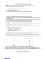
The U.S. Government's Occupational Safety and Health Administration (OSHA) has specified the following permissible noise level
exposures.
Duration Per Day In Hours Sound Level dBA, Slow Response
890
692
495
397
2 100
1 1/2 102
1 105
1/2 110
1/4 or less 115
According to OSHA, any exposure in excess of the above permissible limits could result in some hearing loss.
Ear plugs or protectors in the ear canals or over the ears must be worn when operating this amplification system in order to prevent a
permanent hearing loss if exposure is in excess of the limits as set forth above. To ensure against potentially dangerous exposure to high
sound pressure levels, it is recommended that all persons exposed to equipment capable of producing high sound pressure levels such as
this amplification system be protected by hearing protectors while this unit is in operation.
SAVE THESE INSTRUCTIONS!
23

-
 1
1
-
 2
2
-
 3
3
-
 4
4
-
 5
5
-
 6
6
-
 7
7
-
 8
8
-
 9
9
-
 10
10
-
 11
11
-
 12
12
-
 13
13
-
 14
14
-
 15
15
-
 16
16
-
 17
17
-
 18
18
-
 19
19
-
 20
20
-
 21
21
-
 22
22
-
 23
23
-
 24
24


Peavey Unity 2002-12 RQ Manual de usuario
- Categoría
- Ecualizadores de audio
- Tipo
- Manual de usuario
En otros idiomas
- français: Peavey Unity 2002-12 RQ Manuel utilisateur
- English: Peavey Unity 2002-12 RQ User manual
- Deutsch: Peavey Unity 2002-12 RQ Benutzerhandbuch
Documentos relacionados
-
Peavey Unity Series 1002-8 RQ El manual del propietario
-
-
-
-
-
-
-
Peavey PV 10 and PV 14 Compact Mixer Manual de usuario