Style Selections 6923WWMV Guía de instalación
- Tipo
- Guía de instalación

1
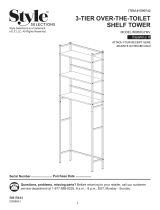
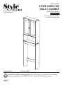
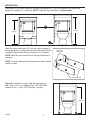
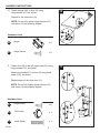
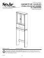
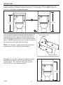
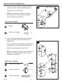
3-TIER OVER-THE
TOILET CABINET
ITEM #1599741
MODEL #6923WWMV
Español p. 13
Serial Number
Purchase Date
Questions, problems, missing parts? Before returning to your retailer, call our customer
service department at 1-877-888-8225, 8 a.m. - 8 p.m., EST, Monday - Sunday.
AR20031
IS6923
Style Selections is a trademarkof LF, LLC.
All Rights Reserved.
ATTACH YOUR RECEIPT HERE
ADJUNTE SU RECIBO AQUÍ

2
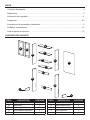
TABLE OF CONTENTS
IS6923
2
Package Contents .......................................................................................................................... 2
Hardware Contents ........................................................................................................................ 3
Safety Information ........................................................................................................................... 4
Preparation ................................................................................................................................... 4-5
Assembly or Installation Instructions ................................................................................................ 6
Care and Maintenance ................................................................................................................... 12
Replacement Parts List .................................................................................................................. 12
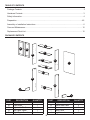
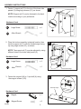
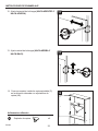
PACKAGE CONTENTS
D
F
E
A
I
H
A
C
H
G
B
PART DESCRIPTION QUANTITY
A Top / Bottom Shelf 2
B Fixed Shelf 1
C Adjustable Shelf 1
D Left Upper Panel 1
E Right Upper Panel 1
PART DESCRIPTION QUANTITY
F Support Rail 2
G Lower Side Panel 2
H Door 2
I Back Panel 1
J Leg Extension 2
F
G
J
J

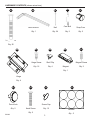
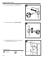
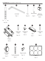
Screw Cap
Qty. 12
HARDWARE CONTENTS (shown actual size)
Large Screw
Qty. 20
Magnet
Qty. 1
3
IS6923
H11
Allen Wrench
Qty. 1
H7
H1
H9
H2
H6
Magnet Screw
Qty. 2
Hinge
Qty. 4
Hinge Screw
Qty. 16
Door Knob
Qty. 2
Knob Screw
Qty. 2
H4
Cam Bolt
Qty. 2
H5
Snap Cam
Qty. 2
H3
Nail
Qty. 24
Stickers
Qty : 3
Shelf Clip
Qty. 4
H8
H12
H15 H16
H10

IS6923
PREPARATION
SAFETY INFORMATION
Please read and understand this entire manual before attempting to assemble, operate or install
the product.
• Before cutting, drilling or hammering into any wall surface, verify the location of electrical,
plumbing and gas lines. Cutting any of these may cause serious injury. If needed, contact
your electrician, plumber or service person.
• It is imperative that the unit be fastened to the wall for safety and stability.
• For safety reasons, it is imperative to use a stepladder.
Before beginning assembly of product, make sure all parts are present. Compare parts with package
contents list and hardware contents list. If any part is missing or damaged, do not attempt to assemble
the product.
Estimated Assembly Time: 45 minutes (with assistance of another person)
Tools Required for Assembly (not included): Phillips Screwdriver, Hammer, Rubber mallet, Pencil,
Power Drill, Drill Bit (1/4 in. drill bit for drywall anchor or 1/8 in. drill bit for direct stud)
Wall Mounting
Screw
Qty. 1
CC
Small Wood
Screw
Qty. 1
DD
Mounting Bracket
Qty. 1
AA
HARDWARE CONTENTS (shown actual size)
4
WALL MOUNT KIT
Wall Anchor
Qty. 1
BB

5
IS6923
PREPARATION
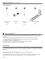
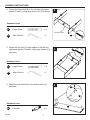
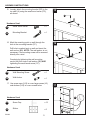
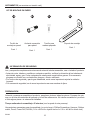
Depending on your toilet height the included leg extensions (J) can be installed to the lower side
panels (G), adding 3 in., as shown. NOTE: Install the leg extensions (J) before step 1.
Insert the lower side panels (G) into the middle channel of
the leg extensions (J), making sure the lower side panels (G) are
completely aligned with the leg extensions (J), as shown.
NOTE: Make sure the closed end of the leg extensions is
facing up.
NOTE: If needed, lightly tap the leg extension with a rubber
mallet to install.
closed end
facing UP
J
G
G
unnished edge
30.75 in.
33.75 in.
Optional: If needed, you may order decorative feet to
add a total of 4.5 in. by calling toll free 1-877-888-8225
between 8 a.m. - 8 p.m., EST, Monday - Sunday.
35.25 in.
J
G

6
IS6923
Hardware Used
Hardware Used
1. Fasten 1 support rail (F) to the top of the lower side
panels (G) using large screws (H1), as shown.
NOTE: Support rail (F) can be fastened in the back
location according to your preference.
2. Place the bottom assembly in desired location, then
install a support rail (F) with the nished edge facing
up using large screws (H1), as shown.
NOTE: The support rail (F) may be adjusted by using
different holes in the lower side panels (G).
1
2
3
G
Large Screw
x 4
H1
H1
Hardware Used
3. Fasten the magnet (H9) to 1 top shelf (A) using
the magnet screws (H10).
Magnet
x 1
H9
Magnet Screw
x 2
H10
ASSEMBLY INSTRUCTIONS
H1
unnished edge
G
G
A
G
unnished edge
Allen Wrench
x 1
H2
Large Screw
x 4
H1
Allen Wrench
x 1
H2
F
H9
H10
unnished edge
back
F

7
IS6923
Hardware Used
Hardware Used
4. Fasten the xed shelf (B) to the left and right upper
panels (D and E) using large screws (H1), as shown.
5. Fasten the top shelf (A) with magnet to the left and
right upper panels (D and E) using large screws (H1),
as shown.
4
5
6
Large Screw
x 4
H1
H1
Hardware Used
6. Attach the cam bolts (H4) to the bottom shelf (A),
as shown.
Cam Bolt
x 2
H4
ASSEMBLY INSTRUCTIONS
H1
D
A
E
unnished edge
Allen Wrench
x 1
H2
Large Screw
x 4
H1
Allen Wrench
x 1
H2
H4
D
B
E
A
A

8
IS6923
ASSEMBLY INSTRUCTIONS
Hardware Used
7. Fasten the bottom shelf (A) to the left and right
upper panels (D and E) using large screws (H1),
as shown.
NOTE: All holes on the xed shelf (B) are
facing down.
7
A
Hardware Used
8. Lay unit face down on oor and attach the
back panel (I) using nails (H3), as shown.
NOTE: The unnished side of the back panel (I)
is facing up.
8
I
Hardware Used
9. Carefully place top assembly onto bottom assembly,
aligning cam bolts (H4) with the holes on the lower
side panels (G) and insert snap cams (H5) into the
holes in the lower side panels (G).
NOTE: If necessary, tap the snap cams (H5) with a
hammer (not included) to secure the top assembly
to the bottom assembly.
9
Snap Cam
x 2
H5
E
G
H5
Large Screw
x 4
H1
Allen Wrench
x 1
H2
D
E
H1
Nail
x 24
H3

9
IS6923
ASSEMBLY INSTRUCTIONS
Hardware Used
10. Fasten hinges (H6) to door (H) using
hinge screws (H7), as shown.
Repeat for the other door (H).
NOTE: Do not fully tighten hinge screws (H7)
until doors (H) are properly aligned.
10
Hardware Used
11. Fasten door (H) to the left upper panel (D) using
hinge screws (H7), as shown.
Attach door knobs (H11) to door (H) using knob
screw (H12), as shown.
Repeat steps for the other door (H).
NOTE: Do not fully tighten hinge screws (H7)
until doors (H) are properly aligned.
11
H
Hinge
x 4
Hinge Screw
x 8
H7
H6
H7
AA
H
Hinge Screw
x 8
Door Knob
x 2
Knob Screw
x 2
H11
H7
H7
H6
H12
H11
H12
H

10
IS6923
ASSEMBLY INSTRUCTIONS
Hardware Used
14. Install adjustable shelf (C) into desired location,
using shelf clips (H8), as shown.
14
C
Shelf Clip
x 4
H8
H8
12. Horizontal hinge adjustment, (IN AND OUT).
12
13. Vertical hinge adjustment, (UP AND DOWN).
13

11
IS6923
15
CC
DD
Hardware Used
15. Loosely attach the mounting bracket (DD) to the
top shelf (A) using the small wood screw (CC),
as shown.
Mounting Bracket
x 1
Small Wood Screw
x 1
ASSEMBLY INSTRUCTIONS
Hardware Used
17. Use screw caps (H15) to cover large screws (H1)
and stickers (H16) to cover unused holes.
17
Screw Cap
x 12
Sticker
x 3
H15
16
AA
CC
Hardware Used
16. Mark the mounting point on wall through the
hole in the mounting bracket (CC).
Drill hole in marked spot on wall and insert the
wall anchor (BB). NOTE: The wall anchor is not
necessary if the mounting screw will be screwed
directly into a stud.
Complete by tightening the wall mounting
screw (AA) into stud or wall anchor (BB) AND
tightening the small wood screw (CC).
Wall Anchor
x 1
Wall Mounting Screw
x 1
BB
H16
H15
BB
AA
DD
CC

12
IS6923
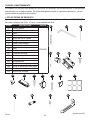
PART DESCRIPTION PART #
H1 Large Screw
YPN6923
H2 Allen Wrench
H3 Nail
H4 Cam Bolt
H5 Snap Cam
H6 Hinge
H7 Hinge Screw
H8 Shelf Clip
H9 Magnet
H10 Magnet Screw
H11 Door Knob
H12 Knob Screw
H15 Screw Cap
H16 Stickers
AA Wall Mounting Screw
BB Wall Anchor
CC Small Wood Screw
DD Mounting Bracket
CARE AND MAINTENANCE
Cleaning with a dry cloth may be sufcient, but for other stains or marks wipe gently with a damp cloth.
DO NOT use strong detergents or abrasive cleaners; they may damage the surface of the product.
Printed in USA
REPLACEMENT PARTS LIST
For replacement parts, call our customer service department at 1-877-888-8225, 8 a.m. - 8 p.m., EST,
Monday - Sunday.
H11
H1
H9
H2
H6H4 H5
H3
H8
H12 H15 H16H10
H7
AA BB CC DD

13
GABINETE DE 3 NIVELES
PARA COLOCAR SOBRE
EL INODORO
ARTÍCULO #1599741
MODELO #6923WWMV
Número de serie
Fecha de compra
¿Preguntas, problemas, piezas faltantes? Antes de volver a la tienda, llame a nuestro
Departamento de Servicio al Cliente al 1-877-888-8225, de lunes a domingo de 8 a.m. a 8
p.m., hora estándar del Este.
IS6923
Style Selections es una marca registrada de LF, LLC.
Todos los derechos reservados.

ÍNDICE
IS6923
14
Contenido del paquete .................................................................................................................. 2
Aditamentos ................................................................................................................................... 3
Información de seguridad ............................................................................................................... 4
Preparación ................................................................................................................................... 4-5
Instrucciones de ensamblaje o instalación ....................................................................................... 6
Cuidado y mantenimiento .............................................................................................................. 12
Lista de piezas de repuesto ........................................................................................................... 12
CONTENIDO DEL PAQUETE
D
F
E
A
I
H
A
C
H
G
B
PIEZA DESCRIPCIÓN CANTIDAD
A Repisa superior o inferior 2
B Repisa ja 1
C Repisa ajustable 1
D Panel superior izquierdo 1
E Panel superior derecho 1
PIEZA DESCRIPCIÓN CANTIDAD
F Riel de soporte 2
G Panel lateral inferior 2
H Puerta 2
I Panel posterior 1
J Extensión para pata 2
F
G
J
J

Tapa de tornillo
Cant. 12
ADITAMENTOS (se muestran en tamaño real)
Tornillo grande
Cant. 20
Imán
Cant. 1
15
IS6923
H11
Llave Allen
Cant. 1
H7
H1
H9
H2
H6
Tornillo para
imán
Cant. 2
Bisagra
Cant. 4
Tornillo para
bisagra
Cant. 16
Perilla de la
puerta
Cant. 2
Tornillo para perilla
Cant. 2
H4
Perno de leva
Cant. 2
H5
Ajuste de
acción rápida
Cant. 2
H3
Clavo
Cant. 24
Autoadhesivos
Cant. 3
Sujetador de
repisa
Cant. 4
H8
H12
H15 H16
H10

IS6923
PREPARACIÓN
INFORMACIÓN DE SEGURIDAD
Lea y comprenda completamente este manual antes de intentar ensamblar, usar o instalar el producto.
• Antes de cortar, taladrar o martillar en cualquier supercie, verique la ubicación de las tuberías de
electricidad, agua y gas. Cortar cualquiera de estas puede causar daños graves. Si es necesario,
póngase en contacto con un electricista, plomero o técnico calicado.
• Por motivos de seguridad y para lograr estabilidad, es de suma importancia sujetar la unidad a
la pared.
• Por razones de seguridad, es de suma importancia usar una escalera de tijera.
Antes de comenzar a ensamblar el producto, asegúrese de tener todas las piezas. Compare las pie-
zas con la lista del contenido del paquete y la lista de aditamentos. No intente ensamblar el producto
si falta alguna pieza o si estas están dañadas.
Tiempo estimado de ensamblaje: 45 minutos
(con la ayuda de otra persona)
Herramientas necesarias para el ensamblaje (no se incluyen): Phillips Screwdriver, Hammer, Rubber
mallet, Pencil, Power Drill, Drill Bit (1/4 in. drill bit for drywall anchor or 1/8 in. drill bit for direct stud)
Tornillo de
montaje en pared
Cant. 1
CC
Tornillo para
madera pequeño
Cant. 1
DD
Soporte de montaje
Cant. 1
AA
ADITAMENTOS (se muestran en tamaño real)
16
KIT DE MONTAJE EN PARED
Ancla de expansión
para pared
Cant. 1
BB

17
IS6923
PREPARACIÓN
Como se muestra, según la altura del inodoro, las extensiones para patas que se incluyen (J) se
pueden instalar en los paneles laterales inferiores (G), lo que agrega 7,62 cm. NOTA: instale las
extensiones para patas (J) antes del paso 1.
Como se muestra, inserte los paneles laterales inferiores (G)
en la canaleta central de las extensiones para patas (J)
y asegúrese de que los paneles laterales inferiores (G)
estén completamente alineados con las extensiones para
patas (J). NOTA: asegúrese de que el extremo cerrado de
las extensiones para patas esté hacia arriba.
NOTA: si es necesario, golpee suavemente la extensión
para pata con un mazo de goma para instalarla.
extremo cerrado hacia
ARRIBA
J
G
G
borde sin terminar
78,1 cm
85,72 cm
Opcional: si es necesario, puede pedir patas decorativas
para agregar un total de 11,43 cm; para ello, llame al
número gratuito 1-877-888-8225, de lunes a domingo,
de 8 a.m. a 8 p.m., hora estándar del Este.
89,53 cm
J
G

18
IS6923
Aditamentos utilizados
Aditamentos utilizados
1. Como se muestra, utilice tornillos grandes (H1) para
ajustar un riel de soporte (F) a la parte superior de los
paneles laterales inferiores (G).
NOTA: el riel de soporte (F) se puede ajustar en la
ubicación posterior según lo desee.
2. Como se muestra, coloque el ensamble inferior en
la ubicación deseada y, luego, utilice tornillos
grandes (H1) para instalar un riel de soporte (F) |
con el borde acabado hacia arriba.
NOTA: se puede jar el riel de soporte (F) al utilizar
diferentes oricios en los paneles laterales inferiores (G).
1
2
3
G
Tornillo grande
x 4
H1
H1
Aditamentos utilizados
3. Utilice los tornillos para imán (H10) para ajustar el
imán (H9) a una repisa superior (A).
Imán
x 1
H9
Tornillo para imán
x 2
H10
INSTRUCCIONES DE ENSAMBLAJE
H1
borde sin terminar
G
G
A
G
borde sin terminar
Llave Allen
x 1
H2
Tornillo grande
x 4
H1
Llave Allen
x 1
H2
F
H9
H10
borde sin terminar
respaldo
F

19
IS6923
Aditamentos utilizados
Aditamentos utilizados
4. Como se muestra, ajuste la repisa ja (B) a los
paneles superiores izquierdo y derecho (D y E) con
los tornillos grandes (H1).
5. Como se muestra, ajuste la repisa superior (A)
con imán a los paneles superiores izquierdo y
derecho (D y E) con los tornillos grandes (H1).
4
5
6
Tornillo grande
x 4
H1
H1
Aditamentos utilizados
6. Como se muestra, je los pernos de leva (H4) a la
repisa inferior (A).
Perno de leva
x 2
H4
INSTRUCCIONES DE ENSAMBLAJE
H1
D
A
E
borde sin terminar
Llave Allen
x 1
H2
Tornillo grande
x 4
H1
Llave Allen
x 1
H2
H4
D
B
E
A
A

20
IS6923
INSTRUCCIONES DE ENSAMBLAJE
Aditamentos utilizados
7. Como se muestra, ajuste la repisa inferior (A) a
los paneles superiores izquierdo y derecho (D y E)
con los tornillos grandes (H1).
NOTA: todos los oricios en la repisa ja (B)
están hacia abajo.
7
A
Aditamentos utilizados
8. Como se muestra, coloque la unidad boca
abajo en el piso y je el panel posterior (I) con
los clavos (H3).
NOTA: el lado sin acabado del panel posterior (I)
está hacia arriba.
8
I
Aditamentos utilizados
9. Coloque con cuidado el ensamble superior sobre el
ensamble inferior y alinee los pernos de leva (H4)
con los oricios en los paneles laterales inferiores (G)
e inserte los ajustes de acción rápida (H5) en los
oricios de los paneles laterales inferiores (G).
NOTA: si es necesario, golpee suavemente los
ajustes de acción rápida (H5) con un martillo
(no se incluye) para asegurar el ensamble superior
al ensamble inferior.
9
Ajuste de acción rápida
x 2
H5
E
G
H5
Tornillo grande
x 4
H1
Llave Allen
x 1
H2
D
E
H1
Clavo
x 24
H3

21
IS6923
INSTRUCCIONES DE ENSAMBLAJE
Aditamentos utilizados
10. Como se muestra, ajuste las bisagras (H6) a la
puerta (H) con los tornillos para bisagra (H7).
Repita para la otra puerta (H).
NOTA: no apriete por completo los tornillos
para bisagra (H7) hasta que las puertas (H)
estén alineadas correctamente.
10
Aditamentos utilizados
11. Como se muestra, ajuste la puerta (H) al panel
superior izquierdo (D) con los tornillos para
bisagra (H7).
Como se muestra, je las perillas de puertas (H11)
a la puerta (H) con el tornillo para perilla (H12).
Repita los pasos para la otra puerta (H).
NOTA: no apriete por completo los tornillos para
bisagra (H7) hasta que las puertas (H) estén
alineadas correctamente.
11
H
Bisagra
x 4
Tornillo para bisagra
x 8
H7
H6
H7
AA
H
Tornillo para bisagra
x 8
Perilla de la puerta
x 2
Tornillo de la perilla
x 2
H11
H7
H7
H6
H12
H11
H12
H

22
IS6923
INSTRUCCIONES DE ENSAMBLAJE
Aditamentos utilizados
14. Como se muestra, instale las repisa ajustable (C)
en la ubicación deseada con sujetadores de
repisa (H8).
14
C
Sujetador de repisa
x 4
H8
H8
12. Ajuste horizontal de la bisagra (HACIA ADENTRO Y
HACIA AFUERA).
12
13. Ajuste vertical de la bisagra (HACIA ARRIBA Y
HACIA BAJO).
13

23
IS6923
15
CC
DD
Aditamentos utilizados
15. Como se muestra, je sin apretar el soporte de
montaje (DD) a la repisa superior (A) con el
tornillo para madera pequeño (CC).
Soporte de montaje
x 1
Tornillo para madera
pequeño
x 1
INSTRUCCIONES DE ENSAMBLAJE
Aditamentos utilizados
17. Utilice las tapas de tornillos (H15) para cubrir los
tornillos grandes (H1) y los autoadhesivos (H16)
para cubrir los oricios sin utilizar.
17
Tapa atornillable
x 12
Autoadhesivos
x 3
H15
16
AA
CC
Aditamentos utilizados
16. Marque el punto de montaje en la pared a través
del oricio del soporte de montaje (CC).
Taladre un oricio en el lugar marcado en
la pared e inserte el ancla de expansión de
pared (BB). NOTA: si el tornillo de montaje se
atornillará directamente en un perno, el ancla
de expansión de pared no es necesario.
Para completar, apriete el tornillo de montaje
en pared (AA) en el montante o en el ancla de
expansión de pared (BB) Y apriete el tornillo
para madera pequeño (CC).
Ancla de expansión
para pared
x 1
Tornillo para montaje
de pared
x 1
BB
H16
H15
BB
AA
DD
CC

24
IS6923
PIEZA DESCRIPCIÓN PIEZA #
H1 Tornillo grande
YPN6923
H2 Llave Allen
H3 Clavo
H4 Perno de leva
H5 Ajuste de acción rápida
H6 Bisagra
H7 Tornillo para bisagra
H8 Sujetador de repisa
H9 Imán
H10 Tornillo para imán
H11 Perilla de la puerta
H12 Tornillo para perilla
H15 Tapa de tornillo
H16 Autoadhesivos
AA Tornillo de montaje en pared
BB Ancla de expansión para pared
CC Tornillo para madera pequeño
DD Soporte de montaje
CUIDADO Y MANTENIMIENTO
La limpieza con un paño seco puede ser suciente. Sin embargo, para otras manchas o marcaslimpie
suavemente con un paño húmedo. NO utilice detergentes fuertes ni limpiadores abrasivos, ya que
pueden dañar la supercie del producto
Impreso en USA
LISTA DE PIEZAS DE REPUESTO
Para obtener piezas de repuesto, llame a nuestro Departamento de Servicio al Cliente al 1-877-888-8225,
de lunes a domingo de 8 a.m. a 8 p.m., hora estándar del Este.
H11
H1
H9
H2
H6H4 H5
H3
H8
H12 H15 H16H10
H7
AA BB CC DD
-
 1
1
-
 2
2
-
 3
3
-
 4
4
-
 5
5
-
 6
6
-
 7
7
-
 8
8
-
 9
9
-
 10
10
-
 11
11
-
 12
12
-
 13
13
-
 14
14
-
 15
15
-
 16
16
-
 17
17
-
 18
18
-
 19
19
-
 20
20
-
 21
21
-
 22
22
-
 23
23
-
 24
24