Style Selections 2065NNMV Guía de instalación
- Tipo
- Guía de instalación

1
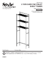
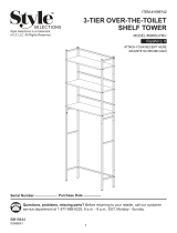
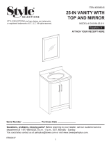
3-TIER OVER-THE-TOILET
SHELF TOWER
ITEM #761374
MODEL #2065NNMV
Español p. 7
Serial Number
Purchase Date
Questions, problems, missing parts? Before returning to your retailer, call our customer
service department at 1-877-888-8225, 8 a.m. - 8 p.m., EST, Monday - Sunday.
AR19011
Style Selections is a trademark of LF,
LLC. All Rights Reserved.
ATTACH YOUR RECEIPT HERE
ADJUNTE SU RECIBO AQUÍ
IS20065-I2

2
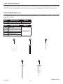
TABLE OF CONTENTS
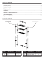
PART DESCRIPTION QUANTITY
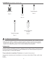
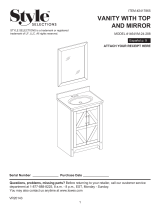
A Top Piece 1
B Shelf 3
C Front Tube 2
Package Contents .......................................................................................................................... 2
Hardware Contents ........................................................................................................................ 3
Safety Information ........................................................................................................................... 3
Preparation ....................................................................................................................................... 3
Assembly or Installation Instructions ................................................................................................ 4
Care and Maintenance ..................................................................................................................... 6
Replacement Parts List .................................................................................................................... 6
PACKAGE CONTENTS
A
B
C
B
F
wall mounting hole
B
C
E
D
wall mounting hole
PART DESCRIPTION QUANTITY
D Back Tube 2
E Bottom Side Panel 2
F Straight Tube 1
D
E
IS20065-I2

Screw
Qty. 14
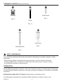
HARDWARE CONTENTS (shown actual size)
Tube Cap
Qty. 8
3
PREPARATION
SAFETY INFORMATION
Please read and understand this entire manual before attempting to assemble, operate or install
the product.
• Before cutting, drilling or hammering into any wall surface, verify the location of electrical,
plumbing and gas lines. Cutting any of these may cause serious injury. If needed, contact
your electrician, plumber or service person.
Before beginning assembly of product, make sure all parts are present. Compare parts with package
contents list and hardware contents list. If any part is missing or damaged, do not attempt to assemble
the product.
Estimated Assembly Time: 25 minutes (with assistance of another person)
Tools Required for Assembly (not included): Phillips Screwdriver, Hammer, Pencil, Level
Wall Anchor
Qty. 2
Mounting Screw
Qty. 2
EE
DD
AA BB
Small Screw
Qty. 4
CC
IS20065-I2

4
Hardware Used
Hardware Used
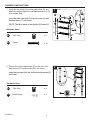
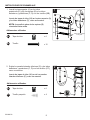
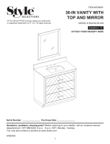
1. Insert the top piece (A) into the back tubes (D) and
attach the shelves (B) to the front and back tubes (C,D)
with screws (BB).
Insert the tube caps (AA) into the top piece (A) and
the front tubes (C), as shown.
NOTE: The at surface of the shelves (B) faces UP.
2. Fasten the bottom side panels (E) to the front and
back tubes (C,D) with screws (CC), as shown.
Insert the tube caps (AA) into the bottom side panels (E),
as shown.
1
2
A
Tube Cap
x 4
AA
Small Screw
x 4
CC
ASSEMBLY INSTRUCTIONS
B
back
C
Screw
x 12
BB
B
B
C
C
wall mounting
hole
D
D
BB
AA
AA
BB
Tube Cap
x 4
AA
E
E
C
CC
E
E
C
D
D
AA
IS20065-I2

ASSEMBLY INSTRUCTIONS
Hardware Used
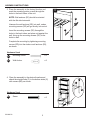
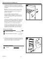
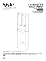
3. Place the assembly in the desired location and
mark the mounting points on wall through the
holes in the back tubes of the unit.
NOTE: Wall anchors (EE) should be oriented
with the at side horizontal.
Hammer the wall anchors (EE) into wall, unless
mounting screws (DD) will go directly into a stud.
Insert the mounting screws (DD) through the
holes in the back tubes and place unit against the
wall, lining up the mounting screws (DD) to the
holes in wall.
Complete the mounting by tightening mounting
screws (DD) into the studs or wall anchors (EE),
as shown.
Wall Anchor
x 2
EE
Mounting Screw
x 2
DD
DD
EE
5
4
Hardware Used
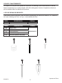
4. Place the assembly in the desired location and
attach the straight tube (F) to the bottom sides (E)
with screws (BB), as shown.
Screw
x 2
BB
B
BB
F
D
3
IS20065-I2

6
IS20065-I2
CARE AND MAINTENANCE
Cleaning with a dry cloth may be sufcient, but for other stains or marks wipe gently with a damp cloth.
DO NOT use strong detergents or abrasive cleaners; they may damage the surface of the product.
REPLACEMENT PARTS LIST
For replacement parts, call our customer service department at 1-877-888-8225, 8 a.m. - 8 p.m., EST,
Monday - Sunday.
Printed in China
EE
DD
AA
CC
BB
PART DESCRIPTION PART #
AA Tube Cap
SS2065NNYP
BB Screw
CC Small Screw
DD Mounting Screw
EE Wall Anchor
PART DESCRIPTION PART #
AA Tube Cap SS2065NNTC

7
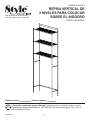
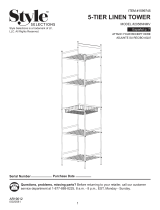
REPISA VERTICAL DE
3 NIVELES PARA COLOCAR
SOBRE EL INODORO
ARTÍCULO #761374
MODELO #2065NNMV
Style Selections es una marca de LF,
LLC. Todos los derechos reservados.
Número de serie
Fecha de compra
¿Preguntas, problemas, piezas faltantes? Antes de volver a la tienda, llame a nuestro
Departamento de Servicio al Cliente al 1-877-888-8225, de lunes a domingo de 8 a.m. a 8 p.m.,
hora estándar del Este.
IS20065-I2

8
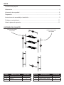
ÍNDICE
PIEZA DESCRIPCIÓN CANTIDAD
A Pieza superior 1
B Repisa 3
C Tubo frontal 2
CONTENIDO DEL PAQUETE
A
B
C
B
F
oricios para montar
en la pared
B
C
E
D
oricios para montar
en la pared
PIEZA DESCRIPCIÓN CANTIDAD
D Tubo posterior 2
E Panel inferior lateral 2
F Tubo recto 1
D
E
Contenido del paquete ................................................................................................................... 7
Aditamentos ................................................................................................................................... 8
Información de seguridad ............................................................................................................... 8
Preparación ...................................................................................................................................... 8
Instrucciones de ensamblaje o instalación ....................................................................................... 9
Cuidado y mantenimiento .............................................................................................................. 11
Lista de piezas de repuesto ........................................................................................................... 11
IS20065-I2

Tornillo
Cant. 14
ADITAMENTOS (se muestran en tamaño real)
Tapa de tubo
Cant. 8
8
PREPARACIÓN
INFORMACIÓN DE SEGURIDAD
Lea y comprenda completamente este manual antes de intentar ensamblar, usar o instalar el producto.
• Antes de cortar, taladrar o martillar en cualquier supercie, verique la ubicación de las tuberías
de electricidad, agua y gas. Cortar cualquiera de estas puede causar daños graves. Póngase en
contacto con su electricista, plomero o con un técnico calicado de ser necesario.
Antes de comenzar a ensamblar el producto, asegúrese de tener todas las piezas. Compare las piezas
con la lista del contenido del paquete y la lista de aditamentos. No intente ensamblar el producto si
falta alguna pieza o si estas están dañadas.
Tiempo estimado de ensamblaje: 25 minutos (con la ayuda de otra persona)
Herramientas necesarias para el ensamblaje (no se incluyen): destornillador Phillips, martillo, lápiz
y nivel
Ancla de expansión
de pared
Cant. 2
Tornillo de montaje
Cant. 2
EE
DD
AA BB
Tornillo pequeño
Cant. 4
CC
IS20065-I2

9
Aditamentos utilizados
Aditamentos utilizados
1. Inserte la pieza superior (A) en los tubos
posteriores (D) y je las repisas (B) a los tubos
delanteros y posteriores (C, D) con los tornillos (BB).
Inserte las tapas de tubo (AA) en la pieza superior (A)
y los tubos delanteros (C), como se muestra.
NOTA: la supercie plana de las repisas (B)
orientadas hacia arriba.
2. Sujete los paneles laterales inferiores (E) a los tubos
delanteros y posteriores (C, D) con los tornillos (CC),
como se muestra.
Inserte las tapas de tubo (AA) en de los paneles
laterales inferiores (E), como se muestra.
1
2
A
Tapa de tubo
x 4
AA
Tornillo pequeño
x 4
CC
INSTRUCCIONES DE ENSAMBLAJE
B
parte
posterior
C
Tornillo
x 12
BB
B
B
C
C
oricio para montaje
en la pared
D
D
BB
AA
AA
BB
Tapa de tubo
x 4
AA
E
E
C
CC
E
E
C
D
D
AA
IS20065-I2

INSTRUCCIONES DE ENSAMBLAJE
Aditamentos utilizados
3. Coloque el ensamble en la ubicación deseada
y marque los puntos de montaje en la pared a
través de los oricios de los tubos posteriores de
la unidad.
NOTA: las anclas de expansión de pared (EE)
deben estar orientadas con el lado plano en
posición horizontal.
Con un martillo ponga las anclas de
expansión (EE) en la pared, a menos que los
tornillos de montaje (DD) vayan directamente
en una viga.
Inserte los tornillos de montaje (DD) a través de
los oricios en los tubos posteriores y apoye la
unidad en la pared, alineando los tornillos de
montaje (DD) con los oricios de la pared.
Termine el montaje apretando los tornillos de
montaje (DD) en las vigas o en las anclas de
expansión de pared (EE), como se muestra.
Ancla de expansión de pared
x 2
EE
Tornillo de montaje
x 2
DD
DD
EE
10
4
Aditamentos utilizados
4. Coloque el ensamble en la ubicación deseada y
je el tubo recto (F) a los costados inferiores (E)
con los tornillos (BB), como se muestra.
Tornillo
x 2
BB
B
BB
F
D
3
IS20065-I2

11
CUIDADO Y MANTENIMIENTO
La limpieza con un paño seco puede ser suciente. Sin embargo, para otras manchas o marcas
limpie suavemente con un paño húmedo. NO utilice detergentes fuertes ni limpiadores abrasivos,
ya que pueden dañar la supercie del producto.
LISTA DE PIEZAS DE REPUESTO
Para obtener piezas de repuesto, llame a nuestro Departamento de Servicio al Cliente al 1-877-888-8225,
de lunes a domingo de 8 a.m. a 8 p.m., hora estándar del Este.
Impreso en China
EE
DD
AA
CC
BB
PIEZA DESCRIPCIÓN PIEZA #
AA Tapa de tubo
SS2065NNYP
BB Tornillo
CC Tornillo pequeño
DD Tornillo de montaje
EE Ancla de expansión de pared
PIEZA DESCRIPCIÓN PIEZA #
AA Tapa de tubo SS2065NNTC
IS20065-I2
-
 1
1
-
 2
2
-
 3
3
-
 4
4
-
 5
5
-
 6
6
-
 7
7
-
 8
8
-
 9
9
-
 10
10
-
 11
11
-
 12
12


Style Selections 2065NNMV Guía de instalación
- Tipo
- Guía de instalación
en otros idiomas
Artículos relacionados
-
 LF 1599742 Manual de usuario
-
 LF 2058NNMV Manual de usuario
-
 Style Selections 8812GYMV Guía de instalación
-
 Style Selections 1678VM-49-292 Guía de instalación
-
 Style Selections 1310VM-25-311 Guía de instalación
-
 Style Selections 1464VM-24-288 Guía de instalación
-
 Style Selections 1544VM-36-290 Guía de instalación
-
 Style Selections 6923WWMV Guía de instalación
-
 Style Selections LWS2308A Guía de instalación
-
 Style Selections SSDR4872CLSV Guía de instalación


